WO2020013085A1 - 液体空気エネルギー貯蔵装置、発電装置及び混焼火力発電システム - Google Patents
液体空気エネルギー貯蔵装置、発電装置及び混焼火力発電システム Download PDFInfo
- Publication number
- WO2020013085A1 WO2020013085A1 PCT/JP2019/026740 JP2019026740W WO2020013085A1 WO 2020013085 A1 WO2020013085 A1 WO 2020013085A1 JP 2019026740 W JP2019026740 W JP 2019026740W WO 2020013085 A1 WO2020013085 A1 WO 2020013085A1
- Authority
- WO
- WIPO (PCT)
- Prior art keywords
- air
- liquid
- heat exchanger
- pressure
- tank
- Prior art date
- Legal status (The legal status is an assumption and is not a legal conclusion. Google has not performed a legal analysis and makes no representation as to the accuracy of the status listed.)
- Ceased
Links
Images



Classifications
-
- H—ELECTRICITY
- H02—GENERATION; CONVERSION OR DISTRIBUTION OF ELECTRIC POWER
- H02J—ELECTRIC POWER NETWORKS; CIRCUIT ARRANGEMENTS OR SYSTEMS FOR SUPPLYING OR DISTRIBUTING ELECTRIC POWER; SYSTEMS FOR STORING ELECTRIC ENERGY
- H02J15/00—Systems for storing electric energy specially adapted for power networks
- H02J15/50—Systems for storing electric energy specially adapted for power networks using stored hydrogen
-
- F—MECHANICAL ENGINEERING; LIGHTING; HEATING; WEAPONS; BLASTING
- F17—STORING OR DISTRIBUTING GASES OR LIQUIDS
- F17C—VESSELS FOR CONTAINING OR STORING COMPRESSED, LIQUEFIED OR SOLIDIFIED GASES; FIXED-CAPACITY GAS-HOLDERS; FILLING VESSELS WITH, OR DISCHARGING FROM VESSELS, COMPRESSED, LIQUEFIED, OR SOLIDIFIED GASES
- F17C6/00—Methods and apparatus for filling vessels not under pressure with liquefied or solidified gases
-
- Y—GENERAL TAGGING OF NEW TECHNOLOGICAL DEVELOPMENTS; GENERAL TAGGING OF CROSS-SECTIONAL TECHNOLOGIES SPANNING OVER SEVERAL SECTIONS OF THE IPC; TECHNICAL SUBJECTS COVERED BY FORMER USPC CROSS-REFERENCE ART COLLECTIONS [XRACs] AND DIGESTS
- Y02—TECHNOLOGIES OR APPLICATIONS FOR MITIGATION OR ADAPTATION AGAINST CLIMATE CHANGE
- Y02E—REDUCTION OF GREENHOUSE GAS [GHG] EMISSIONS, RELATED TO ENERGY GENERATION, TRANSMISSION OR DISTRIBUTION
- Y02E60/00—Enabling technologies; Technologies with a potential or indirect contribution to GHG emissions mitigation
- Y02E60/30—Hydrogen technology
- Y02E60/32—Hydrogen storage
-
- Y—GENERAL TAGGING OF NEW TECHNOLOGICAL DEVELOPMENTS; GENERAL TAGGING OF CROSS-SECTIONAL TECHNOLOGIES SPANNING OVER SEVERAL SECTIONS OF THE IPC; TECHNICAL SUBJECTS COVERED BY FORMER USPC CROSS-REFERENCE ART COLLECTIONS [XRACs] AND DIGESTS
- Y02—TECHNOLOGIES OR APPLICATIONS FOR MITIGATION OR ADAPTATION AGAINST CLIMATE CHANGE
- Y02E—REDUCTION OF GREENHOUSE GAS [GHG] EMISSIONS, RELATED TO ENERGY GENERATION, TRANSMISSION OR DISTRIBUTION
- Y02E70/00—Other energy conversion or management systems reducing GHG emissions
- Y02E70/30—Systems combining energy storage with energy generation of non-fossil origin
Definitions
- the present invention relates to a liquid air energy storage device, a power generation device, and a co-firing power generation system.
- the apparatus disclosed in Patent Document 1 includes a liquefaction facility 81 for liquefying air in the atmosphere, and a storage tank 82 for storing liquefied air liquefied by the liquefaction facility 81.
- the liquefaction facility 81 includes a first heat exchanger 81a that cools air to about ⁇ 150 ° C. using cold heat of liquefied natural gas (LNG), and a pressure of about 80 atm for the air cooled in the heat exchanger 81a.
- LNG cold heat of liquefied natural gas
- the liquid air stored in the storage tank 82 is supplied to the power generation equipment 83 and used for power generation.
- the liquid-air energy storage device disclosed in Patent Document 1 has a configuration in which air is cooled using only liquefied natural gas, so that air must be compressed by the compressor 81b. That is, while LNG is about -160 ° C., the condensation temperature of air is about -190 ° C., so that air cannot be liquefied at normal pressure. For this reason, in order to liquefy air with the cold heat of LNG, it is necessary to compress the air to a high pressure. Therefore, there is a problem that an enormous amount of power is required to generate energy and store liquid air using LNG as a cold heat source.
- An object of the present invention is to reduce the power required to store liquid air as energy.
- a liquid air energy storage device includes a first heat exchanger for pre-cooling air with liquefied natural gas, and a second heat exchanger for cooling and liquefying the air pre-cooled with the first heat exchanger with liquid hydrogen.
- the co-firing thermal power generation system 10 is a thermal power generation system using liquefied natural gas (LNG) and liquid hydrogen (LH2) as fuels, and the system 10 includes liquid air energy.
- a storage device (hereinafter, simply referred to as a storage device) 12 and a co-firing thermal power generation facility (hereinafter, simply referred to as a power generation facility) 14 are provided.
- the air is cooled using liquefied natural gas and liquid hydrogen to generate liquid air.
- high-pressure steam is generated by burning the liquefied natural gas and liquid hydrogen used in the storage device 12, and the high-pressure steam drives the turbine 14a to generate power.
- the storage device 12 includes a tank 16 for storing liquid air, an air line 17 for liquefying air, an LNG line 18 for flowing liquefied natural gas, and a liquid hydrogen line 19 for flowing liquid hydrogen. .
- One end of the LNG line 18 is connected to an LNG tank 21 in which liquefied natural gas is stored.
- One end of the liquid hydrogen line 19 is connected to an LH2 tank 23 in which liquid hydrogen is stored.
- the LNG line 18 and the liquid hydrogen line 19 are provided with pumps 18a and 19a, respectively.
- the pump 18 a of the LNG line 18 sucks the liquefied natural gas from the LNG tank 21 and circulates the liquefied natural gas in the LNG line 18.
- the pump 19 a of the liquid hydrogen line 19 sucks the liquid hydrogen from the LH2 tank 23 and circulates the liquid hydrogen in the liquid hydrogen line 19.
- the air line 17 has one end open so that air (air) can be introduced.
- the other end of the air line 17 is connected to the tank 16.
- a blower 31, a first heat exchanger 33, and a second heat exchanger 35 are arranged in this order.
- the blower 31 is a pressurizer that pressurizes air so that air flows toward the tank 16 in the air line 17.
- the blower 31 since the pressure in the tank 16 is set to about the atmospheric pressure, the blower 31 may pressurize the air to a pressure at which the pressure loss is added to the atmospheric pressure.
- the first heat exchanger 33 is also connected to the LNG line 18.
- the first heat exchanger 33 cools the air flowing through the air line 17 with the liquefied natural gas flowing through the LNG line 18.
- the temperature of liquefied natural gas is about -160 ° C, which is higher than the condensation temperature of air under atmospheric pressure (-190 ° C). Therefore, in the first heat exchanger 33, air does not condense.
- the second heat exchanger 35 is disposed downstream of the first heat exchanger 33 in the air flow direction in the air line 17. Therefore, the air cooled by the liquefied natural gas in the first heat exchanger 33 is introduced into the second heat exchanger 35.
- the second heat exchanger 35 is also connected to the liquid hydrogen line 19, and cools the air flowing through the air line 17 with the liquid hydrogen flowing through the liquid hydrogen line 19.
- the temperature of liquid hydrogen is about -250 ° C., lower than the condensation temperature of air at atmospheric pressure. Therefore, in the second heat exchanger 35, the air condenses. That is, in the first embodiment, the air can be liquefied in the air line 17 without being compressed to a high pressure.
- the downstream end of the LNG line 18 and the downstream end of the liquid hydrogen line 19 are connected to the power generation facility 14, respectively. Therefore, the liquefied natural gas used to pre-cool the air before condensing the air is supplied to the power generation facility 14 as fuel. Then, the liquid hydrogen used to liquefy the air is supplied to the power generation facility 14 as fuel.
- the tank 16 is connected to the downstream end of the air line 17 (the end opposite to the open one end). Therefore, the liquid air liquefied in the second heat exchanger 35 flows into the tank 16.
- the tank 16 is connected to a lead-out line 38 for leading out liquid air.
- the lead-out line 38 is provided with a liquid air pump 41, a carburetor 42, and an air turbine 43.
- the downstream end (the end opposite to the connection end with the tank 16) of the lead-out line 38 is connected to the power generation facility 14.
- the liquid air pump 41 operates in response to a power generation request, and gives a driving force for sending the liquid air to the vaporizer 42 to the liquid air.
- the vaporizer 42 heat-exchanges the liquid air with air or water to vaporize the liquid air. Thereby, high-pressure air is obtained.
- the high-pressure air obtained by the carburetor 42 drives an air turbine 43, thereby generating power. That is, the liquid air pump 41, the vaporizer 42, and the air turbine 43 function as a power generation unit that vaporizes the liquid air stored in the tank 16 and generates power using the vaporized air in response to a power generation request.
- high-pressure air that has driven the air turbine 43 is introduced into the power generation facility 14.
- high-pressure air may be mixed with fuel gas and used for combustion, or high-pressure air may be used to drive a turbine connected to a generator.
- the air turbine 43 may be omitted. Further, instead of the outlet line 38 being connected to the power generation facility 14, the outlet line 38 may be configured to discharge the high-pressure air obtained by the vaporizer 42 into the atmosphere. Further, the vaporizer 42 may be omitted to discharge the liquid air into the atmosphere.
- the air flowing through the air line 17 and the liquefied natural gas flowing through the LNG line 18 exchange heat, and the air is cooled to, for example, about -155 ° C. That is, since the air is not cooled to the condensing temperature, it flows out of the first heat exchanger 33 as air without being condensed.
- the air cooled in the first heat exchanger 33 flows into the second heat exchanger 35.
- the second heat exchanger 35 air exchanges heat with liquid hydrogen flowing through the liquid hydrogen line 19. Since the temperature of the liquid hydrogen is about ⁇ 250 ° C., in the second heat exchanger 35, the air condenses to liquid air. That is, in the air line 17, a heat exchanger 33 that performs heat exchange with liquefied natural gas is disposed at a preceding stage, and a heat exchanger 35 that performs heat exchange with liquid hydrogen at a lower temperature than liquefied natural gas is disposed at a subsequent stage. Are located. Therefore, the cold heat of liquefied natural gas and liquid hydrogen can be effectively used. Since the air is condensed only by the cold heat of the liquid hydrogen in the second heat exchanger 35, the first heat exchanger 33 functions as a heat exchanger that performs pre-cooling before condensing the air.
- the liquefied natural gas whose air has been cooled by the first heat exchanger 33 and the liquid hydrogen whose air has been condensed by the second heat exchanger 35 are both supplied to the power generation facility 14.
- Liquefied natural gas and liquid hydrogen are combusted in power plant 14 and used to generate high pressure steam. Then, the turbine 14a is driven by the high-pressure steam to generate power.
- the liquid air condensed in the second heat exchanger 35 is stored in the tank 16.
- the pressure in the tank 16 becomes substantially constant at a pressure slightly higher than the atmospheric pressure.
- the liquid air stored in the tank 16 is sucked by the liquid air pump 41 and flows through the outlet line 38.
- This liquid air is heated by the vaporizer 42 and vaporized, and becomes high-pressure air.
- the liquid air is vaporized by being heated by water or air.
- the high-pressure air drives the air turbine 43 and is used for power generation.
- the high-pressure air is also provided to the power generation facility 14 and is also used for power generation in the power generation facility 14.
- the charge / discharge efficiency is high and may exceed 200%. Therefore, in the energy balance of charge and discharge, the amount of power generation can exceed the amount of charge. Further, the present invention can be applied to a process in which liquefied natural gas and liquid hydrogen are consumed in large amounts, and the cold heat of liquefied natural gas and liquid hydrogen can be effectively used.
- the air cooled by the liquefied natural gas in the first heat exchanger 33 is further cooled by the liquid hydrogen in the second heat exchanger 35.
- the air becomes liquid air and is stored in the tank 16. That is, energy can be stored as liquid air.
- liquid hydrogen having a temperature lower than the condensation temperature of air is used. For this reason, it is not necessary to compress the air, or even if the air is compressed, the power required for compressing the air can be reduced as compared with the case where the air is liquefied only with liquefied natural gas. Therefore, it is possible to store more energy in the tank 16 than power required for storage. Therefore, charge and discharge efficiency can be increased.
- the storage device 12 is configured as a component of the co-firing thermal power generation system 10, but is not limited thereto.
- the storage device 12 may be configured as a component of a power generation device other than co-firing power generation. That is, while power is generated in the air turbine 43, liquefied natural gas and liquid hydrogen may be used for applications other than power generation.
- the configuration is such that the liquid air energy stored in the storage device 12 is extracted as electric energy.
- the configuration is not limited to this.
- a configuration in which mechanical energy or cold heat is taken out instead of electric energy may be adopted. The same applies to the following embodiments.
- FIG. 2 shows a second embodiment.
- the same components as those in the first embodiment are denoted by the same reference numerals, and detailed description thereof will be omitted.
- the storage device 12 has the control unit 48, and the control unit 48 is connected to the conversion equipment 50 that converts renewable energy into electric energy.
- the conversion facility 50 includes, for example, a solar power generation facility, a solar thermal power generation facility, a wind power generation facility, a hydroelectric power generation facility, a wave power generation facility, or the like.
- the conversion equipment 50 outputs a signal indicating the surplus power. This signal is input to the control unit 48.
- the filling amount of the liquid air is determined according to the electric power surplus represented by this signal. Therefore, the signal requests the signal representing the required filling amount of the liquid air or charging in the storage device 12. Function as a charge request signal for
- the liquid hydrogen line 19 is provided with a flow meter 19b for detecting the flow rate of the liquid hydrogen flowing through the liquid hydrogen line 19.
- the flow meter 19b outputs a signal corresponding to the detected flow rate.
- the signal output from the flow meter 19b is input to the control unit 48.
- the liquid hydrogen flow rate and the liquefied natural gas flow rate are flow rates in accordance with a request issued from the power generation facility 14.
- the tank 16 is provided with a level sensor 16a that outputs a signal corresponding to the amount of stored liquid air.
- the signal output from the level sensor 16a is input to the control unit 48.
- the control unit 48 monitors a flow rate of the liquid hydrogen and a required filling amount of the liquid air, a flow rate determination unit 53 that determines the rotation speed of the blower 31 based on the monitoring result by the monitoring unit 52, A generation determining unit 54 that determines whether liquid air can be generated based on a signal output from the level sensor 16a.
- the monitoring unit 52 indicates the first derivation unit 52a that calculates an air flow rate according to the amount of liquid air that can be generated by the power surplus represented by the signal output from the conversion facility 50, and the signal output from the flow meter 19b.
- a second deriving unit 52b that calculates an air flow rate according to the liquid air amount that can be generated from the liquid hydrogen flow rate.
- the flow rate determining unit 53 compares the air flow rate calculated by the first deriving unit 52a with the air flow rate obtained by the second deriving unit 52b, and derives a smaller amount of air flow as a set flow rate. And a determination unit 53b that determines the rotation speed of the blower 31 based on the set flow rate derived by the generation amount derivation unit 53a.
- the control unit 48 controls the motor of the blower 31 to rotate the blower 31 at a rotation speed according to the result determined by the flow rate determining unit 53 when the generation determining unit 54 determines that liquid air can be generated. Outputs control signal.
- the rotation speed of the blower 31 is adjusted by this control signal. That is, the blower 31 functions as a flow rate adjusting unit that adjusts the flow rate of the air flowing toward the tank 16 according to the determination result of the flow rate determining unit 53.
- the control unit 48 receives a signal from the level sensor 16a of the tank 16 (Step ST1).
- the generation determining unit 54 determines whether liquid air can be generated based on the signal (step ST2). That is, whether or not liquid air can be generated is determined depending on whether or not the tank 16 is fully filled. If the inside of the tank 16 is filled with liquid air, the determination in step ST2 is NO, and no liquid air is generated (step ST3).
- step ST2 when it is determined that the tank 16 can be further filled with the liquid air (YES in step ST2), the control unit 48 acquires the signal output from the conversion equipment 50, and The signal output from the flow meter 19b on the line 19 is obtained (steps ST4 and ST5). Steps ST4 and ST5 may be executed before step ST2.
- control unit 48 determines whether or not the signal output from the conversion equipment 50 has been received (step ST6). That is, control unit 48 determines whether or not a signal output when a surplus power has occurred in conversion equipment 50 has been received. If the signal has not been received, the process proceeds to step ST3. When the signal is received, the process proceeds to step ST7, and the control unit 48 calculates the liquefiable air amount. That is, the control unit 48 receives the charging request indicating the surplus power amount of the renewable energy, and determines the amount of air liquefaction indicated by the charging request as the charging amount.
- the first deriving unit 52a calculates an air flow rate according to the amount of liquid air that can be generated by the power surplus represented by the signal output from the conversion facility 50, and the second deriving unit 52b calculates the air flow rate.
- An air flow rate corresponding to the liquid air amount that can be generated from the liquid hydrogen flow rate detected by 19b is calculated.
- the generation amount deriving unit 53a compares the air flow rate calculated by the first deriving unit 52a with the air flow rate obtained by the second deriving unit 52b, and as a result of the comparison, determines a smaller air flow rate. Set the flow rate.
- the determination section 53b determines the rotation speed of the blower 31 according to the set flow rate, and the control section 48 operates the blower 31 at the determined rotation speed. To output a control signal.
- the blower 31 operates at a rotation speed according to the control signal (step ST8).
- the control unit 48 acquires the motor power of the blower 31 operated according to the control signal (step ST9), and adjusts the rotation speed so that the blower 31 is driven by the power obtained by subtracting the power.
- the liquid air stored in the tank 16 is sucked by the liquid air pump 41 and flows through the outlet line 38 according to the power generation request, and is heated and vaporized by the vaporizer 42 to become high-pressure air.
- the high-pressure air drives the air turbine 43 and is used for power generation.
- the high-pressure air is also provided to the power generation facility 14 and is also used for power generation in the power generation facility 14.
- an appropriate air flow rate can be obtained according to the flow rate of liquid hydrogen and the required filling amount of liquid air. That is, the flow rate determination unit 53 determines the flow rate of the air flowing toward the tank 16 so as to be a flow rate corresponding to the required filling amount of the liquid air, or the flow rate of the liquid supplied to the second heat exchanger 35. The flow rate is determined so as to correspond to the flow rate of hydrogen. Then, the rotation speed of the blower 31 is adjusted according to the result so that the flow rate of the air is obtained. Therefore, it can be adjusted to an appropriate air flow rate.
- FIG. 4 shows a third embodiment of the present invention.
- the same components as those in the first embodiment are denoted by the same reference numerals, and detailed description thereof will be omitted.
- liquid air is stored in the tank 16 at a pressure close to the atmospheric pressure, and the blower 31 provided in the air line 17 pressurizes the air to such an extent that the air flows.
- the liquid air is stored in the tank 16 while being compressed at a level considerably higher than the atmospheric pressure. Therefore, in the third embodiment, a compressor 57 is provided in the air line 17 instead of the blower 31.
- the compressor 57 for compressing the air is disposed upstream of the first heat exchanger 33 and the second heat exchanger 35 in the air line 17. Therefore, air pressurized to a pressure higher than the atmospheric pressure is introduced into the second heat exchanger 35. Therefore, the condensation temperature of air can be raised. For this reason, although power for compressing air is required, the amount of liquefied air can be increased as compared with the first embodiment. That is, in the first embodiment, the liquefied natural gas is used only for pre-cooling the air, and the liquid hydrogen is responsible for the liquefaction of the air. For this reason, the amount of liquefied air depends on the flow rate of liquid hydrogen. In addition, although charging efficiency is high, there are cases where quick charging requests cannot be met. On the other hand, in the third embodiment, the cold heat of the liquefied natural gas is also used for liquefying the air. Therefore, it is possible to meet a request for quick charging.
- the compressor 57 has a plurality of compression stages. That is, the compressor 57 includes a first compression stage 57a configured to compress air, and a second compression stage 57b configured to further compress the air compressed by the first compression stage 57a. ing. However, in the present embodiment, the present invention is not limited to this, and the compressor 57 may have a configuration having a single-stage compression stage, or may have a configuration having three or more compression stages. .
- the first compression stage 57a and the second compression stage 57b may be configured such that the rotation speed of the driving machine can be adjusted.
- the compressor 57 (the first compression stage 57a and the second compression stage 57b) also functions as a flow rate adjustment unit that adjusts the flow rate of the air flowing toward the tank 16.
- a cooler 58 for cooling the air compressed by the compressor 57 is provided in the air line 17.
- the cooler 58 has a first cooling unit 58a that cools the air compressed by the first compression stage 57a, and a second cooling unit 58b that cools the air compressed by the second compression stage 57b. Seawater or air can be used as a cold heat source of the cooler 58. Note that the cooler 58 does not need to be provided for all the compression stages 57a and 57b, and a part of the cooling unit may be omitted. Further, the cooler 58 may be omitted.
- a bypass line 60 for bypassing the final compression stage 57b is connected to the air line 17.
- One end of the bypass line 60 is connected between the first cooling section 58a (or the first compression stage 57a) and the second compression stage 57b in the air line 17.
- the other end of the bypass line 60 is connected between the second cooling section 58b (or the second compression stage 57b) in the air line 17 and the first heat exchanger 33.
- the bypass line 60 and the air line 17 include a switching mechanism 62 that switches between a state in which the air compressed by the first compression stage 57a flows to the second compression stage 57b and a state in which the air is bypassed to the second compression stage 57b.
- the switching mechanism 62 includes a first opening / closing valve 62a arranged in the bypass line 60 and a second opening / closing valve 62b arranged between the connection ends of the bypass line 60 in the air line 17.
- the switching mechanism 62 is not limited to the configuration configured by the first on-off valve 62a and the second on-off valve 62b.
- the switching mechanism 62 may be configured by a three-way valve arranged at a connection between the air line 17 and the bypass line 60.
- the tank 16 is provided with a pressure sensor 64 for detecting the pressure in the tank 16 and a pressure regulating valve 65 for adjusting the pressure in the tank 16.
- the pressure regulating valve 65 is opened and closed according to the pressure detected by the pressure sensor 64.
- the air before being liquefied in the second heat exchanger 35 is compressed by the compressor 57, it is possible to increase the temperature at which the air is liquefied. For this reason, it is possible not only to liquefy the air in the second heat exchanger 35 but also to partially liquefy the air in the first heat exchanger 33.
- a pressure regulating valve 65 that is controlled to open and close according to the pressure detected by the pressure sensor 64 is provided in the tank 16. For this reason, the pressure in the tank 16 is adjusted by opening and closing the pressure regulating valve 65, whereby the pressure in the air line 17 is adjusted. That is, the pressure setting of the air is changed according to the amount of the cooling load of the liquefied natural gas and the liquid hydrogen.
- each compression stage 57a, 57b of the compressor 57 has a region (pressure ratio and flow rate) where it can be operated efficiently, it becomes motively advantageous in consideration of the characteristics of each compression stage 57a, 57b.
- the switching mechanism 62 can appropriately respond to the set pressure by switching whether to bypass the compression stage 57b on the subsequent stage according to the set value of the pressure.
- the flow rate of hydrogen flowing through the liquid hydrogen line 19 is kept low.
- the air is liquefied by the cold heat of the liquefied natural gas. By doing so, it is possible to suppress the air liquefaction amount from being limited.
- FIG. 5 shows a fourth embodiment of the present invention.
- the same components as those of the second embodiment and the third embodiment are denoted by the same reference numerals, and detailed description thereof will be omitted.
- the LNG line 18 and the liquid hydrogen line 19 are provided with flow meters 18b and 19b, respectively, and the tank 16 is provided with a level sensor 16a and a pressure sensor 64.
- the flow meter 18b of the LNG line 18 detects the flow rate of LNG flowing through the LNG line 18, and outputs a signal indicating the detected flow rate.
- the flow meter 19b of the liquid hydrogen line 19 detects the flow rate of the liquid hydrogen flowing through the liquid hydrogen line 19, and outputs a signal indicating the detected flow rate.
- the level sensor 16a outputs a signal indicating the amount of liquid air stored in the tank 16.
- the pressure sensor 64 detects the pressure in the tank 16 and outputs a signal indicating the detected pressure.
- the signals output from the flow meters 18b and 19b, the level sensor 16a, and the pressure sensor 64 are input to the control unit 48.
- the pressure sensor 64 does not need to be disposed in the tank 16, and may be disposed in a portion of the air line 17 between the compressor 57 and the tank 16.
- the control unit 48 includes a monitoring unit 67 that monitors the required filling amount of the liquid air, a pressure determination unit 68 that determines the pressure of the liquid air to be filled in the tank 16 based on the monitoring result by the monitoring unit 67, and a pressure determination unit. It is determined whether or not liquid air can be generated based on a signal output from the pressure adjustment unit 70 that controls the switching mechanism 62 and the pressure regulating valve 65 and the level sensor 16a of the tank 16 according to the set pressure determined by the pressure sensor 68. And a generation judging unit 54 for determining whether or not the data is to be determined.
- the pressure determining unit 68 determines the pressure of the liquid air based on the signal output when the power surplus occurs in the conversion equipment 50 so that the required filling amount of the liquid air can be satisfied.
- the pressure adjusting unit 70 determines the number of stages of use of the compressor 57 in accordance with the set pressure determined by the pressure determining unit 68, and adjusts the opening of the pressure regulating valve 65 or controls opening and closing. That is, the pressure adjusting unit 70 switches the control signal for driving the first compression stage 57a and the second compression stage 57b of the compressor 57 and the switching mechanism 62 based on the set pressure determined by the pressure determining unit 68. It outputs a control signal and a control signal for opening and closing the pressure regulating valve 65.
- the control unit 48 receives a signal from the level sensor 16a of the tank 16 (Step ST11).
- the generation determining unit 54 determines whether liquid air can be generated based on the signal (step ST12). If the inside of the tank 16 is filled with liquid air, the determination in step ST12 is NO, and no liquid air is generated (step ST13).
- the control unit 48 acquires the signal output from the conversion equipment 50 and sets the LNG line. Signals output from the flow meter 18b of the liquid crystal line 18 and the flow meter 19b of the liquid hydrogen line 19 are obtained (steps ST14 and ST15). Steps ST14 and ST15 may be executed before step ST12.
- step ST16 when the control unit 48 receives a signal output when a surplus power is generated in the conversion equipment 50 (step ST16), the control unit 48 controls the liquid stored in the tank 16 based on the surplus power.
- the air pressure is calculated (step ST17). That is, when the pressure in the tank 16 is set to the atmospheric pressure, the air cannot be liquefied by the liquefied natural gas, so that the air is liquefied only by the liquid hydrogen. For this reason, when liquid air is obtained based on hydrogen cold heat, the amount of cold heat of liquid hydrogen may be insufficient for the required charging amount. On the other hand, when the pressure in the tank 16 is set to a pressure higher than the atmospheric pressure, the air can be liquefied by the liquefied natural gas.
- the pressure determination unit 68 of the control unit 48 determines the set pressure of the liquid air in the tank 16 based on the power surplus indicated by the signal output from the conversion equipment 50.
- the pressure adjusting unit 70 determines the number of stages of use of the compressor 57 and controls the switching mechanism 62 to switch to the determined number of stages of use (step ST18). Specifically, the pressure adjusting unit 70 determines whether to compress the air in the second compression stage 57b or to bypass the second compression stage 57b according to the determined set pressure of the liquid air. Then, based on the result of this determination, it is determined whether or not the switching of the switching mechanism 62 is necessary.
- the pressure value of the liquid air is obtained from the pressure sensor 64 disposed in the tank 16 (step ST19), and the pressure in the tank 16 is adjusted by the pressure adjusting unit 70 controlling the opening and closing of the pressure regulating valve 65. (Step ST20).
- the motor power of the compressor 57 is obtained (step ST21), and the motor rotation speed of the compressor 57 is adjusted (step ST22).
- the compressor 57 may be configured by the compressor 57 having a constant motor rotation speed, and steps ST21 and ST22 may be omitted.
- the pressure determination unit 68 determines the pressure of the liquid air filled in the tank 16 based on the monitoring result of the monitoring unit 67. That is, if the pressure of the liquid air filled in the tank 16 is increased, the temperature at which the air is liquefied increases. For this reason, in the first heat exchanger 33, it is possible to liquefy a part of the air with the liquefied natural gas. Therefore, the pressure determining unit 68 determines the pressure of the liquid air to be charged into the tank 16 based on the result of monitoring the required charged amount of liquid air, so that an appropriate liquefied amount can be set. By controlling the switching mechanism 62 and the pressure regulating valve 65, the pressure of the liquid air filled in the tank 16 can be adjusted.
- the liquid-air energy storage device includes a first heat exchanger for pre-cooling air with liquefied natural gas, and cooling and liquefying the air pre-cooled with the first heat exchanger with liquid hydrogen.
- the air cooled by the liquefied natural gas in the first heat exchanger is further cooled by the liquid hydrogen in the second heat exchanger.
- the air becomes liquid air and is stored in the tank. That is, energy can be stored as liquid air.
- liquid hydrogen that is lower than the condensation temperature of air is used, so there is no need to compress air, or even if air may be compressed, air is liquefied only with liquefied natural gas.
- the power required for compressing the air can be reduced as compared with the case where the compression is performed. Therefore, it is possible to store more energy in the tank than power required for storage.
- the charge / discharge efficiency can be increased.
- the liquid-air energy storage device may further include a compressor that compresses air before being liquefied by the second heat exchanger.
- the air cooled to liquid hydrogen in the second heat exchanger is compressed and pressurized. Therefore, the boiling point of the liquid air (or the condensation temperature of the air) is higher than that of the liquid air at normal pressure. For this reason, it is possible not only to liquefy the air in the second heat exchanger but also to partially liquefy the air in the first heat exchanger. Therefore, although more compression power is required, the amount of liquid air obtained can be increased. In addition, a part of the air can be liquefied by the cold heat of the liquid hydrogen. Therefore, the power required for compressing air can be reduced as compared with the case where air is liquefied only with liquefied natural gas. When, for example, liquid air is used for power generation, the charge / discharge efficiency decreases, but the power generation amount can be increased.
- the liquid-air energy storage device monitors a flow rate of the liquid hydrogen and a required filling amount of the liquid air, and determines a flow rate of the air flowing toward the tank based on a monitoring result by the monitoring section.
- the air conditioner may further include a flow rate determining unit that determines the flow rate, and a flow rate adjusting unit that adjusts a flow rate of the air flowing toward the tank according to a determination result of the flow rate determining unit.
- an appropriate air flow rate can be obtained according to the flow rate of liquid hydrogen and the required filling amount of liquid air. That is, the flow rate determination unit determines the flow rate of the air flowing toward the tank to be a flow rate corresponding to the required filling amount of the liquid air, or the flow rate of the liquid hydrogen supplied to the second heat exchanger. The flow rate is determined according to Then, the flow rate adjusting unit adjusts the flow rate of the air according to the result. Therefore, it can be adjusted to an appropriate air flow rate.
- the blower which can adjust a rotation speed the compressor which can adjust a rotation speed, etc. can be used as a flow-rate adjustment part.
- the compressor used for adjusting the temperature at which the air is liquefied or the condensing temperature of the air is used as the flow rate adjusting unit. Can also function.
- the liquid-air energy storage device has a plurality of compression stages, and a compressor for compressing air before being liquefied by the second heat exchanger, and a compression stage on a subsequent stage in the compressor.
- the air before being liquefied by the second heat exchanger is compressed by the compressor, it is possible to increase the temperature at which the air is liquefied. For this reason, it is possible not only to liquefy the air in the second heat exchanger but also to partially liquefy the air in the first heat exchanger.
- the pressure in the tank can be adjusted by the pressure regulating valve. For this reason, the pressure in the tank is adjusted by opening and closing the pressure regulating valve, thereby adjusting the pressure in the air line. Since the switching mechanism is provided, it is possible to appropriately cope with the set pressure while considering the characteristics of each compression stage.
- the liquid-air energy storage device includes a monitoring unit that monitors a required filling amount of the liquid air, and a pressure determination unit that determines a pressure of the liquid air to be filled in the tank based on a monitoring result by the monitoring unit. And a pressure adjusting unit that controls the switching mechanism and the pressure regulating valve according to the determination result of the pressure determining unit.
- the pressure determination unit determines the pressure of the liquid air to be charged into the tank based on the monitoring result by the monitoring unit. That is, if the pressure of the liquid air filled in the tank is increased, the temperature at which the air is liquefied increases. For this reason, in the first heat exchanger, it is possible to liquefy a part of the air with the liquefied natural gas. Therefore, the pressure determination unit can set an appropriate liquefied amount by determining the pressure of the liquid air to be charged into the tank based on the monitoring result of the required charged amount of liquid air. Then, by controlling the switching mechanism and the pressure regulating valve, the pressure of the liquid air filled in the tank can be adjusted.
- the power generation device includes: the liquid-air energy storage device; and a power generation unit that vaporizes the liquid air stored in the tank and generates power using the vaporized air in response to a power generation request. It has.
- the energy of the liquefied air stored in the tank can be extracted as electric power.
- the co-firing thermal power generation system includes the liquid-air energy storage device, a vaporizer that vaporizes the liquid air stored in the tank, air vaporized by the vaporizer, and the first heat.
- a co-firing power plant that generates power using liquefied natural gas that has passed through the exchanger and liquid hydrogen that has passed through the second heat exchanger.
- the energy of the liquefied air stored in the tank can be extracted as electric power.
- liquefied natural gas and liquid hydrogen used for liquefying air can be used as fuel, efficient operation of the entire system is possible.
- the power required to store liquid air as energy can be reduced.
Landscapes
- Engineering & Computer Science (AREA)
- Mechanical Engineering (AREA)
- General Engineering & Computer Science (AREA)
- Power Engineering (AREA)
- Filling Or Discharging Of Gas Storage Vessels (AREA)
Abstract
混焼火力発電システムは、液体空気エネルギー貯蔵装置と混焼火力発電設備とを備えている。液体空気エネルギー貯蔵装置は、液化天然ガスによって空気を予冷する第1熱交換器と、第1熱交換器で予冷された空気を液体水素によって冷却して液化させる第2熱交換器と、第2熱交換器で液化した液体空気を貯蔵するタンクと、を備えている。発電設備は、タンクに貯蔵された液体空気を気化させる気化器と、気化器で気化した空気と、第1熱交換器を通過した液化天然ガスと、第2熱交換器を通過した液体水素と、を用いて発電を行う。
Description
本発明は、液体空気エネルギー貯蔵装置、発電装置及び混焼火力発電システムに関する。
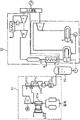
従来、下記特許文献1に開示されているように、空気を冷却して液体空気として蓄える液体空気エネルギー貯蔵装置が知られている。具体的に、特許文献1に開示された装置は、図7に示すように、大気中の空気を液化する液化設備81と、液化設備81で液化された液化空気を貯蔵する貯蔵用タンク82と、を備えている。液化設備81には、液化天然ガス(LNG)の冷熱を利用して空気を約-150℃程度に冷却する第1の熱交換器81aと、熱交換器81aにおいて冷却された空気を80気圧程度に圧縮する圧縮機81bと、圧縮機81bによって圧縮された空気を高圧のままさらに約-160℃程度に冷却する複数の熱交換器81cと、熱交換器81cにおいて冷却された空気を自由膨張させる膨張機構81dと、を備えている。熱交換器81cで低温となった空気が膨張機構81dによって急速に自由膨張することによって、一部が液化し、液体空気が貯蔵用タンク82に貯蔵される。貯蔵用タンク82に貯蔵された液体空気は、発電設備83に供給されて、発電に利用される。
特許文献1に開示された液体空気エネルギー貯蔵装置では、液化天然ガスのみを用いて空気を冷却する構成であるため、圧縮機81bによる空気の圧縮が必要となっている。すなわち、LNGは約-160℃である一方で、空気の凝縮温度は約-190℃であるため、常圧で空気を液化することはできない。このため、LNGの冷熱で空気を液化するには、空気を高圧に圧縮する必要がある。したがって、LNGを冷熱源として液体空気を生成してエネルギー貯蔵を行うには、莫大な動力が必要になるという問題がある。
本発明の目的は、液体空気をエネルギーとして貯蔵するのに要する動力を低減できるようすることにある。
本発明の一局面に係る液体空気エネルギー貯蔵装置は、液化天然ガスによって空気を予冷する第1熱交換器と、前記第1熱交換器で予冷された空気を液体水素によって冷却して液化させる第2熱交換器と、前記第2熱交換器で液化した液体空気を貯蔵するタンクと、を備えている。
以下、添付図面を参照しながら、実施の形態について説明する。なお、以下の実施の形態は、本発明を具体化した一例であって、本発明の技術的範囲を限定する性格のものではない。
(第1実施形態)
図1に示すように、第1実施形態に係る混焼火力発電システム10は、液化天然ガス(LNG)及び液体水素(LH2)を燃料とする火力発電システムであり、当該システム10は、液体空気エネルギー貯蔵装置(以下単に、貯蔵装置と称する)12と、混焼火力発電設備(以下単に、発電設備と称する)14と、を備えている。貯蔵装置12では、液化天然ガス及び液体水素を用いて空気が冷却され、液体空気が生成される。発電設備14では、貯蔵装置12で利用された後の液化天然ガス及び液体水素を燃焼させて高圧蒸気が生成され、この高圧蒸気によってタービン14aが駆動されて発電が行なわれる。
図1に示すように、第1実施形態に係る混焼火力発電システム10は、液化天然ガス(LNG)及び液体水素(LH2)を燃料とする火力発電システムであり、当該システム10は、液体空気エネルギー貯蔵装置(以下単に、貯蔵装置と称する)12と、混焼火力発電設備(以下単に、発電設備と称する)14と、を備えている。貯蔵装置12では、液化天然ガス及び液体水素を用いて空気が冷却され、液体空気が生成される。発電設備14では、貯蔵装置12で利用された後の液化天然ガス及び液体水素を燃焼させて高圧蒸気が生成され、この高圧蒸気によってタービン14aが駆動されて発電が行なわれる。
貯蔵装置12は、液体空気を貯めるためのタンク16と、空気を液化させるための空気ライン17と、液化天然ガスを流すLNGライン18と、液体水素を流す液体水素ライン19と、を備えている。LNGライン18の一端部は、液化天然ガスが貯留されたLNGタンク21に接続されている。液体水素ライン19の一端部は、液体水素が貯留されたLH2タンク23に接続されている。LNGライン18及び液体水素ライン19には、それぞれポンプ18a,19aが設けられている。LNGライン18のポンプ18aは、LNGタンク21から液化天然ガスを吸引して、LNGライン18内に液化天然ガスを流通させる。液体水素ライン19のポンプ19aは、LH2タンク23から液体水素を吸引して、液体水素ライン19内に液体水素を流通させる。
空気ライン17は、一端部が開放していて、大気(空気)を導入可能となっている。空気ライン17の他端部はタンク16に接続されている。空気ライン17には、ブロア31と、第1熱交換器33と、第2熱交換器35とがこの順に配置されている。
ブロア31は、空気ライン17においてタンク16に向けて空気が流れるように空気を加圧する加圧器である。第1実施形態では、タンク16内の圧力が大気圧程度に設定されるため、ブロア31は、大気圧に圧力損失分を加えた程度の圧力に空気を加圧すればよい。
第1熱交換器33は、LNGライン18にも接続されている。第1熱交換器33は、LNGライン18を流れる液化天然ガスによって空気ライン17を流れる空気を冷却させる。液化天然ガスの温度は、約-160℃であって、大気圧下での空気の凝縮温度(-190℃)よりも高い。このため、第1熱交換器33においては、空気は凝縮しない。
第2熱交換器35は、空気ライン17において、空気の流れる方向における第1熱交換器33の下流側に配置されている。したがって、第2熱交換器35には、第1熱交換器33において液化天然ガスによって冷却された空気が導入される。第2熱交換器35は、液体水素ライン19にも接続されており、液体水素ライン19を流れる液体水素によって空気ライン17を流れる空気を冷却させる。液体水素の温度は、約-250℃であって、大気圧下での空気の凝縮温度よりも低い。このため、第2熱交換器35において、空気は凝縮する。すなわち、第1実施形態では、空気ライン17において、空気を高圧に圧縮しないで液化させることができる。
LNGライン18の下流端及び液体水素ライン19の下流端は、それぞれ発電設備14に接続されている。したがって、空気を凝縮させる前に空気を予冷するのに利用された液化天然ガスが発電設備14に燃料として供給される。そして、空気を液化させるのに利用された液体水素が発電設備14に燃料として供給される。
タンク16は、空気ライン17の下流端(開放された一端部と反対側の端)に接続されている。したがって、タンク16には、第2熱交換器35において液化した液体空気が流入する。
タンク16には、液体空気を導出させる導出ライン38が接続されている。導出ライン38には、液体空気ポンプ41と、気化器42と、空気タービン43とが設けられている。導出ライン38の下流端(タンク16との接続端と反対側の端部)は、発電設備14に接続されている。
液体空気ポンプ41は、発電要求に応じて作動し、液体空気を気化器42に送る駆動力を液体空気に与える。気化器42は、液体空気を空気や水と熱交換させて液体空気を気化させる。これにより高圧空気が得られる。気化器42で得られた高圧の空気は、空気タービン43を駆動し、これにより、発電が行われる。すなわち、液体空気ポンプ41、気化器42及び空気タービン43は、発電要求に応じて、タンク16に貯蔵された液体空気を気化させるとともに、気化した空気で発電を行う発電部として機能する。
空気タービン43を駆動した高圧の空気は、発電設備14に導入される。発電設備14では、高圧空気を燃料ガスに混合して燃焼用として利用してもよく、あるいは、高圧空気を発電機に接続されたタービンを駆動するのに利用してもよい。
なお、空気タービン43は、省略されてもよい。また、導出ライン38が発電設備14に接続されるのではなく、導出ライン38は、気化器42で得られた高圧の空気を大気中に放出するように構成されていてもよい。また、気化器42を省略して液体空気を大気中に放出してもよい。
ここで、混焼火力発電システム10の運転動作について説明する。空気ライン17のブロア31が作動すると、大気(空気)が空気ライン17に吸引される。この空気は空気ライン17を流れる。一方、LNGライン18のポンプ18aと液体水素ライン19のポンプ19aも作動する。これにより、LNGタンク21内の液化天然ガスがLNGライン18に吸入されて、LNGライン18を流れる。また、LH2ランク内の液体水素が液体水素ライン19に吸入されて、液体水素ライン19を流れる。
第1熱交換器33において、空気ライン17を流れる空気とLNGライン18を流れる液化天然ガスとが熱交換し、空気は例えば-155℃程度に冷却される。すなわち、空気は、凝縮温度までは冷却されないため、凝縮することなく空気のまま第1熱交換器33から流出する。
第1熱交換器33で冷却された空気は第2熱交換器35に流入する。第2熱交換器35においては、空気は液体水素ライン19を流れる液体水素と熱交換する。液体水素の温度は、約-250℃であるため、第2熱交換器35において、空気は凝縮し、液体空気となる。すなわち、空気ライン17において、前段に液化天然ガスとの熱交換を行う熱交換器33が配置され、その後段に、液化天然ガスよりも低温の液体水素との熱交換を行う熱交換器35が配置されている。したがって、液化天然ガス及び液体水素の冷熱を有効利用することができる。第2熱交換器35において空気は液体水素の冷熱によってのみ凝縮するため、第1熱交換器33は、空気の凝縮前の予冷を行う熱交換器として機能している。
第1熱交換器33で空気を冷却した液化天然ガス及び第2熱交換器35で空気を凝縮させた液体水素は、何れも発電設備14に供給される。液化天然ガス及び液体水素は、発電設備14において燃焼され、高圧蒸気を生成させるのに用いられる。そして、高圧蒸気によってタービン14aが駆動され、発電が行われる。
第2熱交換器35において凝縮した液体空気は、タンク16に貯留される。タンク16内の圧力は大気圧よりも僅かに高い圧力で略一定となる。タンク16内に貯留された液体空気は、液体空気ポンプ41に吸引されて導出ライン38を流れる。この液体空気は、気化器42で加熱されて気化し、高圧の空気となる。なお、気化器42では、液体空気は、水や空気によって加熱されて気化する。
この高圧の空気は、空気タービン43を駆動して、発電に供せられる。また、高圧の空気は発電設備14にも供せられ、発電設備14での発電にも供せられる。
第1実施形態では、ブロア31、ポンプ18a,19a及び液体空気ポンプ41の駆動動力が必要になるだけであるため、充放電効率が高く、200%を超える場合も起こり得る。したがって、充放電のエネルギー収支では、発電量が充電量を上回ることが可能である。また、液化天然ガスと液体水素を大量に消費するプロセスに適用でき、液化天然ガス及び液体水素の冷熱を有効に利用することができる。
以上説明したように、第1実施形態では、第1熱交換器33において液化天然ガスによって冷却された空気が、第2熱交換器35においてさらに液体水素によって冷却される。これにより、空気は液体空気となり、タンク16に貯蔵される。すなわち、液体空気としてエネルギーを貯蔵することができる。第1実施形態では、空気を液化させるにあたり、空気の凝縮温度よりも低温の液体水素が用いられる。このため、空気を圧縮する必要がなく、あるいは空気を圧縮することがあるとしても、液化天然ガスのみで空気を液化させる場合に比べて空気の圧縮に要する動力を低減することができる。したがって、貯蔵するために必要な動力以上のエネルギーをタンク16に貯蔵することが可能となる。したがって、充放電効率を高くすることができる。
なお、第1実施形態では、貯蔵装置12が混焼火力発電システム10の構成要素として構成されているが、これに限られない。例えば、貯蔵装置12は、混焼火力発電以外の発電装置の構成要素として構成されていてもよい。すなわち、空気タービン43において発電を行う一方で、液化天然ガス及び液体水素は、発電以外の用途に用いられてもよい。
また、第1実施形態では、貯蔵装置12に貯蔵された液体空気エネルギーを電気エネルギーとして取り出す構成としたが、これに限られない。電気エネルギーではなく、機械エネルギー又は冷熱を取り出す構成としてもよい。以下の実施形態でも同様である。
(第2実施形態)
図2は第2実施形態を示す。尚、ここでは第1実施形態と同じ構成要素には同じ符号を付し、その詳細な説明を省略する。
図2は第2実施形態を示す。尚、ここでは第1実施形態と同じ構成要素には同じ符号を付し、その詳細な説明を省略する。
第2実施形態では、貯蔵装置12が制御部48を有しており、制御部48は、再生可能エネルギーを電気エネルギーに変換する変換設備50に接続されている。変換設備50は、例えば、太陽光発電設備、太陽熱発電設備、風力発電設備、水力発電設備又は波力発電設備等によって構成されている。変換設備50は、再生可能エネルギーから得られた電力に余剰分が生じた場合に、この電力余剰分を表す信号を出力する。この信号は制御部48に入力される。制御部48では、この信号が表す電力余剰分に応じて、液体空気の充填量が決定されるため、当該信号は、液体空気の要求充填量を表す信号又は貯蔵装置12での充電を要求するための充電要求信号としても機能する。
液体水素ライン19には、液体水素ライン19を流れる液体水素の流量を検出する流量計19bが設けられている。流量計19bは、検出された流量に応じた信号を出力する。流量計19bから出力された信号は制御部48に入力される。なお、液体水素流量及び液化天然ガス流量は、発電設備14から出される要求に応じた流量となっている。
タンク16には、貯留されている液体空気の量に応じた信号を出力するレベルセンサ16aが設けられている。レベルセンサ16aから出力された信号は、制御部48に入力される。
制御部48は、液体水素の流量及び液体空気の要求充填量を監視する監視部52と、監視部52による監視結果に基づいてブロア31の回転数を決定する流量決定部53と、タンク16のレベルセンサ16aから出力された信号に基づいて、液体空気を生成することが可能か否かを決定する生成判断部54と、を備えている。監視部52は、変換設備50から出力された信号が表す電力余剰分によって生成可能な液体空気量に応じた空気流量を算出する第1導出部52aと、流量計19bから出力された信号が示す液体水素流量から生成可能な液体空気量に応じた空気流量を算出する第2導出部52bと、を含む。
流量決定部53は、第1導出部52aによって算出された空気流量と、第2導出部52bによって得られた空気流量とを比較し、より少ない方の空気流量を設定流量として導出する生成量導出部53aと、生成量導出部53aによって導出された設定流量に基づいて、ブロア31の回転数を決定する決定部53bと、を含む。制御部48は、生成判断部54によって液体空気の生成が可能と判断された場合において、流量決定部53による決定結果に応じた回転数でブロア31を回転させるべく、ブロア31のモータを制御する制御信号を出力する。この制御信号によってブロア31の回転数が調整される。すなわち、ブロア31は、流量決定部53の決定結果に従って、タンク16に向けて流れる空気の流量を調整する流量調整部として機能する。
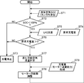
ここで、図3を参照しつつ、第2実施形態に係る貯蔵装置12の運転動作について説明する。まず、制御部48は、タンク16のレベルセンサ16aからの信号を受信する(ステップST1)。生成判断部54は、この信号に基づいて、液体空気を生成することが可能か否かを決定する(ステップST2)。つまり、タンク16が満充填されているかどうかに応じて、液体空気を生成できるかどうかを決定する。タンク16内が液体空気で満たされた状態である場合は、ステップST2での判断がNOとなり、液体空気の生成を行わない(ステップST3)。一方、タンク16内に更なる液体空気を充填することが可能と判断された場合(ステップST2においてYES)には、制御部48は、変換設備50から出力された信号を取得するとともに、液体水素ライン19の流量計19bから出力された信号を取得する(ステップST4,ST5)。なお、ステップST4及びステップST5は、ステップST2の前に実行してもよい。
そして、制御部48は、変換設備50から出力された信号を受信したか否かを判断する(ステップST6)。すなわち、制御部48は、変換設備50に電力余剰分が生じた場合に出力される信号を受信したか否かを判断する。当該信号の受信が無いときにはステップST3に移る。当該信号の受信があると、ステップST7に移行し、制御部48は、液化可能な空気量を計算する。すなわち、制御部48は、再生可能エネルギーの余剰電力量を示す充電要求を受け取り、この充電要求が示す量の空気液化量を充電量として決定する。具体的には、第1導出部52aは、変換設備50から出力された信号が表す電力余剰分によって生成可能な液体空気量に応じた空気流量を算出し、第2導出部52bは、流量計19bによって検出された液体水素流量から生成可能な液体空気量に応じた空気流量を算出する。そして、生成量導出部53aは、第1導出部52aによって算出された空気流量と、第2導出部52bによって得られた空気流量との比較を行い、比較の結果、より少ない方の空気流量を設定流量とする。生成量導出部53aによって設定流量が決定されると、決定部53bは、設定流量に応じたブロア31の回転数を決定し、制御部48は、決定された回転数でブロア31を作動するように制御信号を出力する。ブロア31はこの制御信号にしたがった回転数で作動する(ステップST8)。このとき、制御部48は、制御信号に従って作動したブロア31のモータ動力を取得し(ステップST9)、この動力分を差し引いた電力でブロア31が駆動されるように回転数を調整する。
ブロア31の回転数が調整されると、それに応じた流量の空気が空気ライン17を流れる。そして、この空気は、第1熱交換器33において液化天然ガスによって予冷された後、第2熱交換器35において液体水素に冷却されて凝縮し、液体空気となる。この液体空気はタンク16に貯留される。新たに貯留された分に応じて、レベルセンサ16aの出力値は変化する。
タンク16内に貯留された液体空気は、発電要求に応じて、液体空気ポンプ41に吸引されて導出ライン38を流れ、気化器42で加熱されて気化し、高圧の空気となる。この高圧の空気は、空気タービン43を駆動して、発電に供せられる。また、高圧の空気は発電設備14にも供せられ、発電設備14での発電にも供せられる。
第2実施形態では、液体水素の流量及び液体空気の要求充填量に応じて適切な空気流量を得ることができる。すなわち、流量決定部53は、タンク16に向けて流す空気の流量を、液体空気の要求充填量に応じた流量になるように決定するか、又は、第2熱交換器35に供給される液体水素の流量に応じた流量になるように決定する。そして、ブロア31は、この結果に従って空気の流量になるように回転数が調整される。したがって、適切な空気流量に調整することができる。
なお、その他の構成、作用及び効果はその説明を省略するが、前記第1実施形態の説明を第2実施形態に援用することができる。
(第3実施形態)
図4は本発明の第3実施形態を示す。尚、ここでは第1実施形態と同じ構成要素には同じ符号を付し、その詳細な説明を省略する。
図4は本発明の第3実施形態を示す。尚、ここでは第1実施形態と同じ構成要素には同じ符号を付し、その詳細な説明を省略する。
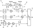
第1実施形態では、タンク16内において、液体空気がほぼ大気圧に近い圧力で貯留され、空気ライン17に設けられたブロア31は、空気が流れる程度に空気を加圧する。これに対し、第3実施形態では、タンク16内において、液体空気が大気圧よりも相当程度高いレベルで圧縮された状態で貯留される。そのため、第3実施形態においては、空気ライン17にブロア31ではなく圧縮機57が設けられている。
空気を圧縮する圧縮機57は、空気ライン17における第1熱交換器33及び第2熱交換器35よりも上流側に配置されている。このため、第2熱交換器35には、大気圧よりも高い圧力まで加圧された空気が導入される。したがって、空気の凝縮温度を上げることができる。このため、空気を圧縮するための動力が必要になるものの、第1実施形態に比べて、空気の液化量を増大させることができる。すなわち、第1実施形態では、液化天然ガスは空気の予冷としてのみ利用され、液体水素が空気の液化を担っている。このため、空気の液化量は液体水素の流量に依存する。また、充電効率は高いが、急速充電要求に応えられない場合がある。これに対し、第3実施形態では、液化天然ガスの冷熱も空気の液化に利用される。したがって、急速充電要求にも応えることができる。
圧縮機57は、複数段の圧縮ステージを有している。すなわち、圧縮機57は、空気を圧縮するように構成された第1圧縮ステージ57aと、第1圧縮ステージ57aで圧縮された空気をさらに圧縮するように構成された第2圧縮ステージ57bとを備えている。ただし、本実施形態では、これに限られるものではなく、圧縮機57は、単段の圧縮ステージを備えた構成であってもよく、あるいは三段以上の圧縮ステージを有する構成であってもよい。
第1圧縮ステージ57a及び第2圧縮ステージ57bは、駆動機の回転数を調整可能な構成としてもよい。この場合、圧縮機57(第1圧縮ステージ57a及び第2圧縮ステージ57b)は、タンク16に向けて流れる空気の流量を調整する流量調整部としても機能する。
空気ライン17には、圧縮機57で圧縮された空気を冷却する冷却器58が設けられている。冷却器58は、第1圧縮ステージ57aで圧縮された空気を冷却する第1冷却部58aと、第2圧縮ステージ57bで圧縮された空気を冷却する第2冷却部58bとを有する。冷却器58の冷熱源としては、海水や空気を用いることができる。なお、冷却器58は、全ての圧縮ステージ57a,57bに対して設けられている必要はなく、一部の冷却部が省略されていてもよい。また、冷却器58は省略されていてもよい。
空気ライン17には、最終圧縮ステージ57bをバイパスするためのバイパスライン60が接続されている。バイパスライン60の一端部は、空気ライン17における第1冷却部58a(又は第1圧縮ステージ57a)と第2圧縮ステージ57bとの間に接続されている。バイパスライン60の他端部は、空気ライン17における第2冷却部58b(又は第2圧縮ステージ57b)と第1熱交換器33との間に接続されている。
バイパスライン60及び空気ライン17には、第1圧縮ステージ57aで圧縮された空気が第2圧縮ステージ57bに流れる状態と、第2圧縮ステージ57bをバイパスする状態との間で切り換えを行う切換機構62が設けられている。切換機構62は、バイパスライン60に配置された第1開閉弁62aと、空気ライン17におけるバイパスライン60の接続端部間に配置された第2開閉弁62bとによって構成されている。
第1開閉弁62aが閉じられ、第2開閉弁62bが開かれることにより、第2圧縮ステージ57b又は最終圧縮ステージから吐出された空気が、第1熱交換器33に向けて流れることになる。一方、第1開閉弁62aが開かれ、第2開閉弁62bが閉じられることにより、空気ライン17に吸入された空気は最終圧縮ステージをバイパスする。すなわち、圧縮機57の各ステージ57a,57bは、圧力比や流量によって動作特性、効率が変化するため、タンク16圧力に応じて最も圧縮動力が小さくなるように、切換機構62が制御される。なお、切換機構62は、第1開閉弁62a及び第2開閉弁62bによって構成される形態に限られない。例えば、切換機構62は、空気ライン17とバイパスライン60との接続部に配置された三方弁によって構成されていてもよい。
タンク16には、タンク16内の圧力を検出する圧力センサ64と、タンク16内の圧力を調整する調圧弁65とが設けられている。調圧弁65は、圧力センサ64の検出圧力に応じて開閉される。
第3実施形態では、第2熱交換器35で液化される前の空気が圧縮機57によって圧縮されるため、空気が液化するときの温度を上げることが可能となる。このため、第2熱交換器35で空気を液化させるだけでなく、第1熱交換器33においても空気の一部を液化させることが可能となる。しかも、圧力センサ64の検出圧力に応じて開閉制御される調圧弁65がタンク16に設けられている。このため、調圧弁65の開閉によってタンク16内の圧力が調整され、これによって、空気ライン17内の圧力が調整される。すなわち、液化天然ガス及び液体水素の冷熱負荷の量に応じて空気の圧力設定が変更される。これにより、液体空気の製造量を調整することができる。一方で、圧縮機57の各圧縮ステージ57a,57bには、効率良く運転できる領域(圧力比や流量)が存在するため、各圧縮ステージ57a,57bの特性を考慮して動力的に有利になるように、後段側の圧縮ステージ57bをバイパスするかどうかを決定する必要がある。したがって、切換機構62が、圧力の設定値に応じて、後段側の圧縮ステージ57bをバイパスするかどうかを切り換えることにより、設定圧力に適切に対応することができる。
発電設備14において、水素混焼率が低く抑えられる場合には、液体水素ライン19を流れる水素流量が低く抑えられることになるが、その場合においても、液化天然ガスの冷熱によって空気を液化する構成とすることにより、空気液化量が制限されることを抑制することができる。
なお、その他の構成、作用及び効果はその説明を省略するが、前記第1実施形態の説明を第3実施形態に援用することができる。
(第4実施形態)
図5は本発明の第4実施形態を示す。尚、ここでは第2実施形態及び第3実施形態と同じ構成要素には同じ符号を付し、その詳細な説明を省略する。
図5は本発明の第4実施形態を示す。尚、ここでは第2実施形態及び第3実施形態と同じ構成要素には同じ符号を付し、その詳細な説明を省略する。
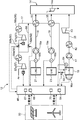
この第4実施形態では、LNGライン18及び液体水素ライン19にそれぞれ流量計18b,19bが設けられ、タンク16には、レベルセンサ16a及び圧力センサ64が設けられている。LNGライン18の流量計18bは、LNGライン18を流れるLNGの流量を検出し、検出流量を示す信号を出力する。液体水素ライン19の流量計19bは、液体水素ライン19を流れる液体水素の流量を検出し、検出流量を示す信号を出力する。レベルセンサ16aは、タンク16に貯留されている液体空気の量を示す信号を出力する。圧力センサ64は、タンク16内の圧力を検出し、検出圧力を示す信号を出力する。流量計18b,19b、レベルセンサ16a及び圧力センサ64から出力された信号は、制御部48に入力される。なお、圧力センサ64は、タンク16に配置される必要はなく、空気ライン17における圧縮機57とタンク16との間の部位に配置されていてもよい。
制御部48は、液体空気の要求充填量を監視する監視部67と、監視部67による監視結果に基づいてタンク16に充填される液体空気の圧力を決定する圧力決定部68と、圧力決定部68によって決定された設定圧力に従って、切換機構62及び調圧弁65を制御する圧力調整部70と、タンク16のレベルセンサ16aから出力された信号に基づいて、液体空気を生成することが可能か否か決定する生成判断部54と、を備えている。圧力決定部68は、変換設備50に電力余剰分が生じた場合に出力される信号に基づいて、液体空気の要求充填量を満たすことができるように、液体空気の圧力を決定する。圧力調整部70は、圧力決定部68によって決定された設定圧力に応じて、圧縮機57の使用段数を決定するとともに、調圧弁65の開度調整又は開閉制御を行う。すなわち、圧力調整部70は、圧力決定部68によって決定された設定圧力に基づいて、圧縮機57の第1圧縮ステージ57a及び第2圧縮ステージ57bを駆動する制御信号、切換機構62を切り換えるための制御信号及び調圧弁65を開閉する制御信号を出力する。
ここで、図6を参照しつつ、第4実施形態に係る貯蔵装置12の運転動作について説明する。まず、制御部48は、タンク16のレベルセンサ16aからの信号を受信する(ステップST11)。生成判断部54は、この信号に基づいて、液体空気を生成することが可能か否かを決定する(ステップST12)。タンク16内が液体空気で満たされた状態である場合は、ステップST12での判断がNOとなり、液体空気の生成を行わない(ステップST13)。一方、タンク16内に更なる液体空気を充填することが可能と判断された場合(ステップST12においてYES)には、制御部48は、変換設備50から出力された信号を取得するとともに、LNGライン18の流量計18b及び液体水素ライン19の流量計19bから出力された信号を取得する(ステップST14,ST15)。なお、ステップST14及びステップST15は、ステップST12の前に実行してもよい。
そして、制御部48が変換設備50に電力余剰分が生じた場合に出力される信号を受信すると(ステップST16)、制御部48は、この電力余剰分に基づいて、タンク16に貯蔵される液体空気の圧力を計算する(ステップST17)。すなわち、タンク16内の圧力が大気圧に設定される場合、液化天然ガスによって空気を液化させることはできないため、液体水素のみによって空気を液化させることになる。このため、水素冷熱を基調として液体空気を得る場合には、充電要求量に対して液体水素の冷熱量が足りない場合が生ずる。これに対し、タンク16内の圧力が大気圧よりも高い圧力に設定される場合には、液化天然ガスによっても空気を液化させることが可能となる。このため、空気ライン17を流れる空気の圧力が高いほど液化天然ガスによる空気の液化量を増大させることができ、充電要求量を満たすことができるようになる。したがって、電力余剰分で表される充電要求量に従って、タンク16内の設定圧力を上げることにより、充電要求量に従った適切な空気液化量を得ることが可能となる。このため、制御部48の圧力決定部68は、変換設備50から出力された信号で示される電力余剰分に基づいて、タンク16内の液体空気の設定圧力を決定する。
液体空気の設定圧力が決定されると、圧力調整部70は、圧縮機57の使用段数を決定するとともに、決定された使用段数になるように切換機構62を切り換える制御を行う(ステップST18)。具体的には、圧力調整部70では、決定された液体空気の設定圧力に応じて、第2圧縮ステージ57bでも空気を圧縮するか、又は第2圧縮ステージ57bをバイパスするかが判断される。そして、この判断結果に応じて、切換機構62の切り換えが必要かどうかが判断される。
続いて、タンク16に配置された圧力センサ64から、液体空気の圧力値を取得し(ステップST19)、圧力調整部70が調圧弁65を開閉制御することにより、タンク16内の圧力調整を行う(ステップST20)。また、圧縮機57のモータ動力を取得し(ステップST21)、圧縮機57のモータ回転数を調整する(ステップST22)。なお、圧縮機57をモータ回転数一定である圧縮機57によって構成しておいて、ステップST21及びST22を省略する構成としてもよい。
第4実施形態では、圧力決定部68は、監視部67による監視結果に基づいて、タンク16に充填される液体空気の圧力を決定する。すなわち、タンク16に充填される液体空気の圧力を上げれば、空気が液化するときの温度が上がる。このため、第1熱交換器33において、液化天然ガスによって空気の一部を液化させることが可能となる。したがって、圧力決定部68が、液体空気の要求充填量の監視結果に基づいて、タンク16に充填される液体空気の圧力を決定することにより、適切な液化量に設定することが可能となる。そして、切換機構62及び調圧弁65を制御することにより、タンク16に充填される液体空気の圧力を調整することができる。
なお、その他の構成、作用及び効果はその説明を省略するが、第1、第2及び第3実施形態の説明を第4実施形態に援用することができる。
ここで、前記実施形態について概説する。
(1)前記実施形態に係る液体空気エネルギー貯蔵装置は、液化天然ガスによって空気を予冷する第1熱交換器と、前記第1熱交換器で予冷された空気を液体水素によって冷却して液化させる第2熱交換器と、前記第2熱交換器で液化した液体空気を貯蔵するタンクと、を備えている。
前記実施形態では、第1熱交換器において液化天然ガスによって冷却された空気が、第2熱交換器においてさらに液体水素によって冷却される。これにより、空気は液体空気となり、タンクに貯蔵される。すなわち、液体空気としてエネルギーを貯蔵することができる。また、空気を液化させるにあたり、空気の凝縮温度よりも低温の液体水素が用いられるため、空気を圧縮する必要がなく、あるいは空気を圧縮することがあるとしても、液化天然ガスのみで空気を液化させる場合に比べて空気の圧縮に要する動力を低減することができる。したがって、貯蔵するために必要な動力以上のエネルギーをタンクに貯蔵することが可能となる。そして、例えば液体空気を発電に用いる場合には、充放電効率を高くすることができる。
(2)前記液体空気エネルギー貯蔵装置は、前記第2熱交換器で液化される前の空気を圧縮する圧縮機をさらに備えていてもよい。
この態様では、第2熱交換器において液体水素に冷却される空気が圧縮されて加圧された状態となっている。このため、常圧の液体空気に比べ、液体空気の沸点(又は空気の凝縮温度)が上昇している。このため、第2熱交換器で空気を液化させるだけでなく、第1熱交換器においても空気の一部を液化させることが可能となる。したがって、圧縮動力がより必要になるものの、得られる液体空気量を増大させることができる。しかも、液体水素の冷熱によっても空気の一部を液化させることができる。したがって、液化天然ガスのみで空気を液化させる場合に比べて空気の圧縮に要する動力を低減することができる。そして、例えば液体空気を発電に用いる場合には、充放電効率が低下することとなるが、発電量を増大させることができる。
(3)前記液体空気エネルギー貯蔵装置は、前記液体水素の流量及び液体空気の要求充填量を監視する監視部と、前記監視部による監視結果に基づいて、前記タンクに向けて流す空気の流量を決定する流量決定部と、前記流量決定部の決定結果に従って、前記タンクに向けて流れる空気の流量を調整する流量調整部と、を備えていてもよい。
この態様では、液体水素の流量及び液体空気の要求充填量に応じて適切な空気流量を得ることができる。すなわち、流量決定部は、タンクに向けて流す空気の流量を、液体空気の要求充填量に応じた流量になるように決定するか、又は、第2熱交換器に供給される液体水素の流量に応じた流量になるように決定する。そして、流量調整部は、この結果に従って空気の流量を調整する。したがって、適切な空気流量に調整することができる。なお、流量調整部としては、回転数を調整することができる送風機、回転数を調整することができる圧縮機等を用いることができる。したがって、第2熱交換器で液化させる前の空気を圧縮する圧縮機を備えた構成では、空気が液化するときの温度又は空気の凝縮温度を調整するのに用いられる圧縮機を流量調整部としても機能させることができる。
(4)前記液体空気エネルギー貯蔵装置は、複数段の圧縮ステージを有し、前記第2熱交換器で液化される前の空気を圧縮する圧縮機と、前記圧縮機における後段側の圧縮ステージをバイパスするバイパスラインと、前記タンクの内圧を監視する圧力センサと、前記タンクの内圧を調整する調圧弁と、前記後段側の圧縮ステージをバイパスさせるかどうかを切り換える切換機構と、を備えていてもよい。
この態様では、第2熱交換器で液化される前の空気が圧縮機によって圧縮されるため、空気が液化するときの温度を上げることが可能となる。このため、第2熱交換器において空気を液化させるだけでなく、第1熱交換器においても空気の一部を液化させることが可能となる。しかも、調圧弁によってタンク内の圧力を調整することができる。このため、調圧弁の開閉によってタンク内の圧力が調整され、これによって、空気ライン内の圧力が調整される。そして、切換機構が設けられているため、各圧縮ステージの特性を考慮しつつ設定圧力に適切に対応することができる。
(5)前記液体空気エネルギー貯蔵装置は、液体空気の要求充填量を監視する監視部と、前記監視部による監視結果に基づいて、前記タンクに充填される液体空気の圧力を決定する圧力決定部と、前記圧力決定部の決定結果に従って、前記切換機構及び前記調圧弁を制御する圧力調整部と、を備えていてもよい。
この態様では、圧力決定部は、監視部による監視結果に基づいて、タンクに充填される液体空気の圧力を決定する。すなわち、タンクに充填される液体空気の圧力を上げれば、空気が液化するときの温度が上がる。このため、第1熱交換器において、液化天然ガスによって空気の一部を液化させることが可能となる。したがって、圧力決定部は、液体空気の要求充填量の監視結果に基づいて、タンクに充填される液体空気の圧力を決定することにより、適切な液化量に設定することが可能となる。そして、切換機構及び調圧弁を制御することにより、タンクに充填される液体空気の圧力を調整することができる。
(6)前記実施形態に係る発電装置は、前記液体空気エネルギー貯蔵装置と、発電要求に応じて、前記タンクに貯蔵された液体空気を気化させるとともに、気化した空気で発電を行う発電部と、を備えている。この発電装置では、タンクに貯蔵された液化空気のエネルギーを電力として取り出すことができる。
(7)前記実施形態に係る混焼火力発電システムは、前記液体空気エネルギー貯蔵装置と、前記タンクに貯蔵された液体空気を気化させる気化器と、前記気化器で気化した空気と、前記第1熱交換器を通過した液化天然ガスと、前記第2熱交換器を通過した液体水素と、を用いて発電を行う混焼火力発電設備と、を備えている。この発電システムでは、タンクに貯蔵された液化空気のエネルギーを電力として取り出すことができる。しかも、空気を液化させるのに利用される液化天然ガス及び液体水素を燃料として利用できるため、システム全体として効率的な運転が可能となる。
以上説明したように、前記実施形態によれば、液体空気をエネルギーとして貯蔵するのに要する動力を低減することができる。
Claims (7)
- 液化天然ガスによって空気を予冷する第1熱交換器と、
前記第1熱交換器で予冷された空気を液体水素によって冷却して液化させる第2熱交換器と、
前記第2熱交換器で液化した液体空気を貯蔵するタンクと、を備えている液体空気エネルギー貯蔵装置。 - 請求項1に記載の液体空気エネルギー貯蔵装置において、
前記第2熱交換器で液化される前の空気を圧縮する圧縮機をさらに備えている液体空気エネルギー貯蔵装置。 - 請求項1に記載の液体空気エネルギー貯蔵装置において、
前記液体水素の流量及び液体空気の要求充填量を監視する監視部と、
前記監視部による監視結果に基づいて、前記タンクに向けて流す空気の流量を決定する流量決定部と、
前記流量決定部の決定結果に従って、前記タンクに向けて流れる空気の流量を調整する流量調整部と、を備えている液体空気エネルギー貯蔵装置。 - 請求項1に記載の液体空気エネルギー貯蔵装置において、
複数段の圧縮ステージを有し、前記第2熱交換器で液化される前の空気を圧縮する圧縮機と、
前記圧縮機における後段側の圧縮ステージをバイパスするバイパスラインと、
前記タンクの内圧を監視する圧力センサと、
前記タンクの内圧を調整する調圧弁と、
前記後段側の圧縮ステージをバイパスさせるかどうかを切り換える切換機構と、を備えている液体空気エネルギー貯蔵装置。 - 請求項4に記載の液体空気エネルギー貯蔵装置において、
液体空気の要求充填量を監視する監視部と、
前記監視部による監視結果に基づいて、前記タンクに充填される液体空気の圧力を決定する圧力決定部と、
前記圧力決定部の決定結果に従って、前記切換機構及び前記調圧弁を制御する圧力調整部と、を備えている液体空気エネルギー貯蔵装置。 - 請求項1から5の何れか1項に記載の液体空気エネルギー貯蔵装置と、
発電要求に応じて、前記タンクに貯蔵された液体空気を気化させるとともに、気化した空気で発電を行う発電部と、を備えている発電装置。 - 請求項1から5の何れか1項に記載の液体空気エネルギー貯蔵装置と、
前記タンクに貯蔵された液体空気を気化させる気化器と、
前記気化器で気化した空気と、前記第1熱交換器を通過した液化天然ガスと、前記第2熱交換器を通過した液体水素と、を用いて発電を行う混焼火力発電設備と、を備えている混焼火力発電システム。
Applications Claiming Priority (2)
| Application Number | Priority Date | Filing Date | Title |
|---|---|---|---|
| JP2018131560A JP2020008132A (ja) | 2018-07-11 | 2018-07-11 | 液体空気エネルギー貯蔵装置、発電装置及び混焼火力発電システム |
| JP2018-131560 | 2018-07-11 |
Publications (1)
| Publication Number | Publication Date |
|---|---|
| WO2020013085A1 true WO2020013085A1 (ja) | 2020-01-16 |
Family
ID=69142593
Family Applications (1)
| Application Number | Title | Priority Date | Filing Date |
|---|---|---|---|
| PCT/JP2019/026740 Ceased WO2020013085A1 (ja) | 2018-07-11 | 2019-07-04 | 液体空気エネルギー貯蔵装置、発電装置及び混焼火力発電システム |
Country Status (2)
| Country | Link |
|---|---|
| JP (1) | JP2020008132A (ja) |
| WO (1) | WO2020013085A1 (ja) |
Cited By (3)
| Publication number | Priority date | Publication date | Assignee | Title |
|---|---|---|---|---|
| CN111623240A (zh) * | 2020-06-16 | 2020-09-04 | 盘锦奥德燃气装备制造有限公司 | 基于液化天然气和压缩天然气的调压计量装置 |
| CN116923712A (zh) * | 2022-04-22 | 2023-10-24 | 通用电气公司 | 使用浸没式泵和压缩天然气的基于氢的燃料分配系统 |
| CN118623208A (zh) * | 2024-05-27 | 2024-09-10 | 同济大学 | 一种基于液氢加氢站冷能回收的空气液化装置及应用 |
Families Citing this family (2)
| Publication number | Priority date | Publication date | Assignee | Title |
|---|---|---|---|---|
| KR102379133B1 (ko) * | 2020-08-13 | 2022-03-29 | 한국기계연구원 | 액체수소 충전소 |
| JP7725386B2 (ja) * | 2022-02-09 | 2025-08-19 | 三菱重工業株式会社 | 冷熱回収設備及び船舶 |
Citations (6)
| Publication number | Priority date | Publication date | Assignee | Title |
|---|---|---|---|---|
| JPH06123553A (ja) * | 1992-10-08 | 1994-05-06 | Osaka Gas Co Ltd | 液化天然ガス冷熱発電設備を組込んだ空気分離方法および装置 |
| JPH11303646A (ja) * | 1998-04-20 | 1999-11-02 | Hitachi Ltd | ガスタービン発電プラント |
| JP2001116198A (ja) * | 1999-08-09 | 2001-04-27 | Osaka Gas Co Ltd | 空気冷却装置 |
| JP2009541522A (ja) * | 2006-06-20 | 2009-11-26 | アーカー エンジニアリング アンド テクノロジー エーエス | Lngを再ガス化する方法およびプラント |
| JP2010208913A (ja) * | 2009-03-12 | 2010-09-24 | Kawasaki Heavy Ind Ltd | ハイブリッド水素供給ステーション |
| JP2011182516A (ja) * | 2010-02-26 | 2011-09-15 | Tamotsu Minagawa | 電力需給平準化システム |
-
2018
- 2018-07-11 JP JP2018131560A patent/JP2020008132A/ja active Pending
-
2019
- 2019-07-04 WO PCT/JP2019/026740 patent/WO2020013085A1/ja not_active Ceased
Patent Citations (6)
| Publication number | Priority date | Publication date | Assignee | Title |
|---|---|---|---|---|
| JPH06123553A (ja) * | 1992-10-08 | 1994-05-06 | Osaka Gas Co Ltd | 液化天然ガス冷熱発電設備を組込んだ空気分離方法および装置 |
| JPH11303646A (ja) * | 1998-04-20 | 1999-11-02 | Hitachi Ltd | ガスタービン発電プラント |
| JP2001116198A (ja) * | 1999-08-09 | 2001-04-27 | Osaka Gas Co Ltd | 空気冷却装置 |
| JP2009541522A (ja) * | 2006-06-20 | 2009-11-26 | アーカー エンジニアリング アンド テクノロジー エーエス | Lngを再ガス化する方法およびプラント |
| JP2010208913A (ja) * | 2009-03-12 | 2010-09-24 | Kawasaki Heavy Ind Ltd | ハイブリッド水素供給ステーション |
| JP2011182516A (ja) * | 2010-02-26 | 2011-09-15 | Tamotsu Minagawa | 電力需給平準化システム |
Cited By (3)
| Publication number | Priority date | Publication date | Assignee | Title |
|---|---|---|---|---|
| CN111623240A (zh) * | 2020-06-16 | 2020-09-04 | 盘锦奥德燃气装备制造有限公司 | 基于液化天然气和压缩天然气的调压计量装置 |
| CN116923712A (zh) * | 2022-04-22 | 2023-10-24 | 通用电气公司 | 使用浸没式泵和压缩天然气的基于氢的燃料分配系统 |
| CN118623208A (zh) * | 2024-05-27 | 2024-09-10 | 同济大学 | 一种基于液氢加氢站冷能回收的空气液化装置及应用 |
Also Published As
| Publication number | Publication date |
|---|---|
| JP2020008132A (ja) | 2020-01-16 |
Similar Documents
| Publication | Publication Date | Title |
|---|---|---|
| JP2020008132A (ja) | 液体空気エネルギー貯蔵装置、発電装置及び混焼火力発電システム | |
| US7406830B2 (en) | Compression-evaporation system for liquefied gas | |
| CN105008834B (zh) | 用于再液化天然气的方法和装置 | |
| EP4575375A1 (en) | Storage unit of carbon dioxide gas-liquid phase change energy storage system, control method therefor, and system | |
| CN101223260A (zh) | 再液化蒸气装置 | |
| JP2019510943A (ja) | 低温液体の蒸発から生じるガスを処理し、ガスエンジンに加圧ガスを供給するシステム | |
| CN105143799A (zh) | 用于生产低温压缩气体或液化气的设备和方法 | |
| WO2021126513A1 (en) | System and method for supplying cryogenic refrigeration | |
| JP2005273681A (ja) | 低温液化ガス貯留システム | |
| US20210063082A1 (en) | A thermodynamic system containing a fluid, and method for reducing pressure therein | |
| AU785125B2 (en) | A method and a device for the liquefaction of natural gas | |
| JP4879321B2 (ja) | 天然ガス液化プラント及びその運転方法 | |
| CN101449115A (zh) | 冷却循环系统、天然气液化设备、冷却循环系统的运转方法及改造方法 | |
| JP4910042B2 (ja) | プラント用動力供給システム、その運転方法及び改造方法 | |
| JP5169107B2 (ja) | 液化ガス貯蔵再液化装置とその運転方法 | |
| JP6665383B2 (ja) | 燃料ガス供給システム及び燃料ガス供給方法 | |
| JP2005221223A (ja) | 気体再液化方法 | |
| EP4325150B1 (fr) | Procédé et appareil de refroidissement d'hydrogène | |
| KR20240028594A (ko) | 장치 | |
| JP6720440B2 (ja) | 燃料ガス供給システム、船舶、及び燃料ガス供給方法 | |
| CN106574513A (zh) | 具有应急燃料系统的发电站设备 | |
| KR20240175311A (ko) | 유체를 극저온으로 냉각하기 위한 설비 및 방법 | |
| WO2023234064A1 (ja) | 気体の液化・気化プラント、及び、気体の液化・気化方法 | |
| JP6668566B2 (ja) | 燃料ガス供給システム、船舶、及び燃料ガス供給方法 | |
| JPH11325714A (ja) | 熱交換式ガス液化装置 |
Legal Events
| Date | Code | Title | Description |
|---|---|---|---|
| 121 | Ep: the epo has been informed by wipo that ep was designated in this application |
Ref document number: 19833146 Country of ref document: EP Kind code of ref document: A1 |
|
| NENP | Non-entry into the national phase |
Ref country code: DE |
|
| 122 | Ep: pct application non-entry in european phase |
Ref document number: 19833146 Country of ref document: EP Kind code of ref document: A1 |