WO2020009224A1 - 引張センサ及びその製造方法 - Google Patents
引張センサ及びその製造方法 Download PDFInfo
- Publication number
- WO2020009224A1 WO2020009224A1 PCT/JP2019/026817 JP2019026817W WO2020009224A1 WO 2020009224 A1 WO2020009224 A1 WO 2020009224A1 JP 2019026817 W JP2019026817 W JP 2019026817W WO 2020009224 A1 WO2020009224 A1 WO 2020009224A1
- Authority
- WO
- WIPO (PCT)
- Prior art keywords
- layer
- conductive layer
- conductive
- resin layer
- electrode portion
- Prior art date
- Legal status (The legal status is an assumption and is not a legal conclusion. Google has not performed a legal analysis and makes no representation as to the accuracy of the status listed.)
- Ceased
Links
Images





Classifications
-
- B—PERFORMING OPERATIONS; TRANSPORTING
- B32—LAYERED PRODUCTS
- B32B—LAYERED PRODUCTS, i.e. PRODUCTS BUILT-UP OF STRATA OF FLAT OR NON-FLAT, e.g. CELLULAR OR HONEYCOMB, FORM
- B32B7/00—Layered products characterised by the relation between layers; Layered products characterised by the relative orientation of features between layers, or by the relative values of a measurable parameter between layers, i.e. products comprising layers having different physical, chemical or physicochemical properties; Layered products characterised by the interconnection of layers
- B32B7/02—Physical, chemical or physicochemical properties
- B32B7/025—Electric or magnetic properties
-
- G—PHYSICS
- G01—MEASURING; TESTING
- G01L—MEASURING FORCE, STRESS, TORQUE, WORK, MECHANICAL POWER, MECHANICAL EFFICIENCY, OR FLUID PRESSURE
- G01L1/00—Measuring force or stress, in general
- G01L1/14—Measuring force or stress, in general by measuring variations in capacitance or inductance of electrical elements, e.g. by measuring variations of frequency of electrical oscillators
-
- G—PHYSICS
- G01—MEASURING; TESTING
- G01L—MEASURING FORCE, STRESS, TORQUE, WORK, MECHANICAL POWER, MECHANICAL EFFICIENCY, OR FLUID PRESSURE
- G01L5/00—Apparatus for, or methods of, measuring force, work, mechanical power, or torque, specially adapted for specific purposes
- G01L5/04—Apparatus for, or methods of, measuring force, work, mechanical power, or torque, specially adapted for specific purposes for measuring tension in flexible members, e.g. ropes, cables, wires, threads, belts or bands
- G01L5/10—Apparatus for, or methods of, measuring force, work, mechanical power, or torque, specially adapted for specific purposes for measuring tension in flexible members, e.g. ropes, cables, wires, threads, belts or bands using electrical means
Definitions
- the present invention relates to a tension sensor and a method for manufacturing the same.
- the tension sensor disclosed in Patent Literature 1 makes a knitted or woven fabric including a plurality of conductive yarns expandable and contractable in one direction and expands and contracts conductive yarns configured to maintain an insulating state. It is intended to detect a change in capacitance from the accompanying change in interval. According to such a tension sensor, since the expansion and contraction of the knitted or woven fabric is detected as a capacitance, no current flows even if a voltage is applied to the conductive yarn, and power consumption in this portion can be made zero. Thus, power consumption can be reduced.
- a tension sensor when a tension sensor is installed on a detection target to detect a deformation or the like of the detection target, if any other dielectric or conductor approaches the tension sensor, noise based on the proximity of the dielectric or conductor may occur.
- the signal is mixed with a signal relating to the deformation of the detection target, which is originally desired to be acquired, and there has been a problem that it is difficult to detect the movement of the detection target, such as elongation, with high accuracy.
- the present invention has been made in order to solve such a problem, the detection accuracy is not easily reduced even if the use is continued, and a high-precision tension sensor which is not easily affected by noise, and It is intended to provide a manufacturing method.
- the object of the present invention is to provide a strip-shaped dielectric layer having a stretchable dielectric layer, and a stretchable first conductive layer and a second conductive layer provided on one surface and the other surface of the dielectric layer, respectively.
- a sensor main body wherein the first conductive layer includes a band-shaped first electrode portion formed of a conductive yarn, and the dielectric layer includes a high-melting resin layer and both surfaces of the high-melting resin layer.
- the melting point of the high melting point resin layer is higher by 40 ° C. or more than the melting points of the first low melting point resin layer and the second low melting point resin layer.
- the second conductive layer includes a band-shaped second electrode portion formed of a conductive yarn, and the second electrode portion is located at a position facing the first electrode portion via the dielectric layer.
- the second low melting point resin layer is impregnated and disposed.
- a stretchable base fabric may be provided in which one surface side of the sensor main body is arranged in a stacked manner, and the stretchable base fabric may have stretch anisotropy.
- the sensor body further includes a tubular elastic base fabric in which one surface side is stacked and arranged, and the sensor body has a longitudinal direction in a direction along a circumferential direction of the tubular elastic base fabric.
- a band-shaped elastic adjustment layer arranged along the circumferential direction of the cylindrical elastic base fabric, one end of the elastic adjustment layer is at least in the vicinity of one end of the sensor body.
- the other end of the elastic adjustment layer is arranged at least near the other end of the sensor main body, and the sensor main body and the elastic adjustment layer have an annular structure on a cylindrical elastic base cloth. May be configured.
- the expansion / contraction adjustment layer is formed of the same material as the high melting point resin layer.
- the object of the present invention is to provide a high-melting-point resin layer and a low-melting-point resin layer provided on both surfaces of the high-melting-point resin layer on one side and the other side of a stretchable dielectric layer, respectively.
- a first conductive layer provided with a band-shaped first electrode portion formed from a knitted fabric structure or a woven structure, and a band-shaped second electrode portion formed from a conductive yarn as a knitted structure or a woven structure
- a tension sensor having steps It is achieved by.
- the pressing step fixes the first conductive layer and the second conductive layer on each other via the non-flowable high-melting-point resin layer.
- the present invention it is possible to provide a high-accuracy tension sensor that is hardly reduced in detection accuracy even when it is continuously used, and that is not easily affected by noise, and a method of manufacturing the same.
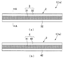
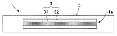
- FIG. 1A is a schematic configuration plan view showing a tension sensor according to the present invention
- FIG. 2B is a schematic configuration back view thereof.
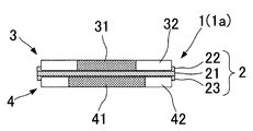
- FIG. 2 is a schematic configuration sectional view showing an AA section in FIG.
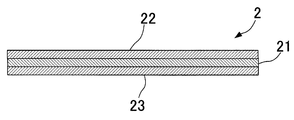
- FIG. 3 is a schematic configuration sectional view for describing a structure of a dielectric layer in FIG. 2. It is an example which shows the knitted fabric cross section of the 1st electrode part and the 2nd electrode part with which the tension sensor which concerns on this invention is provided, ( ⁇ a ⁇ ) ⁇ is non-extension
- (A) is a schematic configuration perspective view showing a modified example of the tension sensor according to the present invention
- (b) is a schematic configuration perspective view showing a configuration without an expansion / contraction adjustment layer included in the modified example.
- (A) is a schematic configuration plan view showing a modified example of the tension sensor according to the present invention
- (b) is a schematic configuration sectional view showing an A'-A 'section thereof
- (c) is a schematic configuration back view. is there.
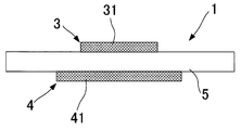
- It is a schematic structure sectional view showing the modification of the tension sensor concerning the present invention.
- (A) is a schematic configuration plan view relating to a sample A of the tension sensor according to the present invention
- (b) is a schematic configuration cross-sectional view showing an A "-A" cross section
- (c) is a schematic configuration back view.
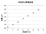
- . 9 is a graph showing the relationship between the elongation rate of sample A and the value of the detected capacitance. It is a schematic structure sectional view for explaining sample C used for a noise influence confirmation test.
- FIG. 1A is a schematic configuration plan view of a sensor main body 1a included in the tension sensor 1 according to the present invention
- FIG. 1B is a schematic configuration back view thereof
- FIG. 2 is a schematic cross-sectional view showing a cross section taken along the line AA of FIG.
- the sensor main body 1a provided in the tension sensor 1 according to the present invention constitutes a sensor that acquires, for example, respiration information (for example, presence or absence of respiration, respiration cycle, etc.) and body movement information (for example, information on limb movement) of a living body.
- the sensor main body 1 a has a rectangular shape in plan view, and is provided on the dielectric layer 2 and on one surface and the other surface of the dielectric layer 2.
- a first conductive layer 3 and a second conductive layer 4 are provided.
- the sensor main body 1a forms a capacitor with the dielectric layer 2, the first conductive layer 3 and the second conductive layer 4 sandwiching the dielectric layer 2, and the first conductive layer accompanying expansion and contraction.
- This is a sensor capable of detecting a change in capacitance between the third conductive layer 4 and the second conductive layer 4.
- the dielectric layer 2 is configured to have elasticity, and is provided on both sides of the sheet-like high melting point resin layer 21 and the high melting point resin layer 21 as shown in the sectional view of FIG. It is configured to include a sheet-like first low-melting resin layer 22 and a second low-melting resin layer 23.
- the dielectric layer 2 is configured so as to have an insulating property that does not allow current to flow through the first conductive layer 3 and the second conductive layer 4 even when they are stacked. It is preferable that the electric resistivity of the dielectric layer 2 is not less than 10 6 ⁇ ⁇ cm and not more than 10 18 ⁇ ⁇ cm.
- thermoplastic elastomer As a material of the high melting point resin layer 21, a thermoplastic elastomer can be exemplified. Particularly, urethane rubber, natural rubber, isoprene rubber, butadiene rubber, styrene / butadiene rubber, butyl rubber, nitrile rubber, ethylene / propylene rubber, chloroprene rubber, acrylic rubber, chlorosulfonated polyethylene rubber, silicone rubber, fluorine rubber, ethylene / acetic acid Various rubber materials such as vinyl rubber and epichlorohydrin rubber are exemplified. Further, additives may be added to the above materials.
- the high melting point resin layer 21 can suitably use one having a melting point of 150 ° or more, more preferably one having a melting point of 180 ° C or more, and further more preferably one having a melting point of 200 ° or more. preferable.
- the first and second low-melting resin layers 22 and 23 preferably have a melting point of 110 ° or more, more preferably 120 ° or more.
- the first and second low-melting resin layers 22 and 23 and the high-melting resin layer 21 are formed using a thermoplastic elastomer included in the same category, for example, both are formed from polyurethane rubber. can do.
- the high melting point resin layer 21 it is preferable to use a material whose melting point is higher by 40 ° C. or more than the melting points of the first and second low melting point resin layers 22 and 23. Further, it is more preferable to use one that is 60 ° C. or higher, and still more preferably one that is 80 ° C. or higher.
- the dielectric layer 2 may be formed in a sponge shape having minute voids therein. With such a sponge-like configuration, the dielectric layer 2 can be easily returned to the initial state (the state before elongation) when the tension state is released.
- the thickness of the high melting point resin layer 21 is not particularly limited, but is preferably set in the range of 5 ⁇ m to 100 ⁇ m, and more preferably in the range of 10 ⁇ m to 75 ⁇ m. Further, it is more preferable to set the range of 20 ⁇ m to 60 ⁇ m.
- the thickness of the first low-melting resin layer 22 and the second low-melting resin layer 23 is not particularly limited, but is preferably configured to have a thickness substantially equal to the thickness of the high-melting resin layer 21 described above.
- the first conductive layer 3 includes a band-shaped first electrode portion 31 and a band-shaped first non-conductive portion 32 on both sides of the first electrode portion 31.
- the second conductive layer 4 has the same configuration as that of the first conductive layer 3, includes a band-shaped second electrode portion 41, and has a band-shaped second non-conductive portion 42 on both sides of the second electrode portion 41. It is provided with.
- the longitudinal direction of the first electrode portion 31 and the first non-conductive portion 32 of the first conductive layer 3 and the longitudinal direction of the second electrode portion 41 and the second non-conductive portion 42 of the second conductive layer 4 are It is set to be in the direction along the longitudinal direction of the strip-shaped sensor main body. Further, the extending direction of the strip-shaped sensor main body is not particularly limited, but may be configured to be able to extend along the longitudinal direction of the sensor main body.
- one side of the first conductive layer 3 and the second conductive layer 4 is embedded in a first low melting point resin layer 22 and a second low melting point resin layer 23 included in the dielectric layer 2. It is arranged in a state. That is, the first electrode portion 31 is disposed in a state where at least a part of the first low melting point resin layer 22 is impregnated, and the second electrode portion 41 is formed such that at least a part of the second low melting point resin layer 23 is formed. It is arranged in an impregnated state.
- the first conductive layer 3 and the second conductive layer 4 have a structure in which the first conductive layer 3 and the second conductive layer 4 are substantially opposed to each other on both sides via the high melting point resin layer 21 provided in the dielectric layer 2. Will have.
- the first conductive layer 3 is configured to have elasticity.
- a conductive thread for forming the first electrode portion 31 and a non-conductive yarn for forming each first non-conductive portion 32 are provided. It is preferable to form a knitted or woven fabric (woven fabric) using conductive yarns.
- the second conductive layer 4 is knitted or woven by using a conductive yarn for forming the second electrode portion 41 and a non-conductive yarn for forming each second non-conductive portion 42. It is preferable to configure it as a finished dough.
- the first conductive layer 3 (the first electrode portion 31 and the first non-conductive portion 32) and the second conductive layer 4 (the second electrode portion) are used as fabrics having a knitted fabric structure formed by knitting.
- the knitted fabric structure is not particularly limited, for example, milling knit, smooth knit, pearl knit, flat knit or a change structure thereof (for example, Milan ribs and corrugated cardboard knit), and tricot knit, Raschel knit, Milanese knit and the like Various knitted fabric structures can be adopted.
- the first conductive layer 3 and the second conductive layer 4 are configured as a woven fabric, examples of the woven fabric structure include plain weave, twill weave, and satin weave.
- the method for manufacturing the first conductive layer 3 and the second conductive layer 4 is not limited to the above-described method. For example, after knitting or weaving the main body of the cloth with non-conductive fibers, conductive yarn is knitted in a predetermined portion.
- the first electrode portion 31 (or the second electrode portion 41) may be formed by embroidery or the like to manufacture.
- the conductive yarn for forming the first electrode portion 31 or the second electrode portion 41 for example, a synthetic fiber (for example, polyester fiber or nylon fiber) or a natural fiber is used as a core, and A metal-coated yarn (plated yarn) to which a metal component is applied by performing wet or dry coating, plating, vacuum film formation, or other appropriate application methods can be used.
- a monofilament for the core a multifilament or a spun yarn, which is an aggregate of a plurality of single fibers, is more preferable than a monofilament, and further, a covering yarn such as a wooly processed yarn or SCY or DCY.
- a bulky yarn such as a fluff yarn is more preferable.
- the metal components to be adhered to the core include, for example, pure metals such as aluminum, nickel, copper, titanium, magnesium, tin, zinc, iron, silver, gold, platinum, vanadium, molybdenum, tungsten, cobalt, alloys thereof, and stainless steel. , Brass or the like can be used.
- the conductive yarn for example, aluminum, nickel, copper, titanium, magnesium, tin, zinc, iron, silver, gold, platinum, vanadium, molybdenum, tungsten, cobalt and other pure metals and alloys thereof, stainless steel, A thread-shaped or strip-shaped metal wire formed of brass or the like, or a thread formed of a conductive fiber such as carbon fiber can be used.
- a covering yarn in which a synthetic fiber or a natural fiber or the like is used as a core and a metal fiber is wound around the core may be used as the conductive yarn.
- the thickness of the conductive yarn is not particularly limited, but the wire diameter per single wire is preferably, for example, 10 to 100 ⁇ m. Above all, a thickness of 10 to 50 ⁇ m is particularly preferable because the flexibility and durability of the first conductive layer 3 and the second conductive layer 4 themselves (the first electrode portion 31 and the second electrode portion 41 themselves) are easily compatible.
- a metal wire When a metal wire is used as the conductive yarn, its surface may be coated with an insulating coating layer.
- the metal wire covered with the insulating coating layer may be a monofilament or a multifilament, and it is particularly preferable to bundle two to nine, more preferably three to seven, and use them as one thread.
- Polyester polyethylene terephthalate, polybutylene terephthalate, polyphenylene sulfide, polyetheretherketone, PFA, PVDF, fluorinated resin such as ETFE, polystyrene, polycarbonate, polysulfone, polyethersulfone, formal (polyvinylformal), butyral (polyvinyl) Butyral).
- fluorinated resin such as ETFE, polystyrene, polycarbonate, polysulfone, polyethersulfone, formal (polyvinylformal), butyral (polyvinyl) Butyral).
- materials that can be used as the insulating coating layer are not limited to these resin types.
- a metal wire insulated with a resin as illustrated is also called an enamel-coated metal wire.
- a general coating method from application of a molten material to drying may be employed.
- a covering yarn (SCY or DCY) is formed by using a metal wire as a core material and using a fibrous (thread-like) insulating coating material (for example, a yarn or a cotton yarn formed from a material usable as the above-mentioned insulating coating layer) as a cover material. It is also possible to adopt a method of forming, and a method of heating and melting the covering yarn to form a coating film.
- the material forming the insulating coating layer has flexibility and elasticity in addition to melting at a solder melting temperature (about 170 ° C. to 250 ° C.). Is recommended. That is, it is preferable to use a thermoplastic resin having a melting point equal to or lower than the melting temperature of the solder for the insulating coating layer. Soldering can be performed in a short time, and the melted insulating coating layer is reliably burned or shrunk and does not disturb the solder portion, so that reliable conduction can be obtained within the range of the melting temperature of the solder. A material having a melting point in a low temperature range ("150 ° C. or less" can be mentioned as an example) can be said to be preferable.
- the selection of the insulating coating layer is not limited to the melting point alone, but one of the conditions is the thickness of the insulating coating layer covering the conductive yarn.
- the melting point of the insulating coating layer is high (the temperature is higher when the standard is set to 150 ° C.), if the coating thickness is small, it will be relatively easily melted at the time of soldering. , And can be used as an insulating coating layer.
- 150 ° C. is given as an example of the solder melting temperature, but this melting temperature varies depending on the resin selected for the insulating coating layer.
- the temperature should be 155 ° C. for polyester, modified polyester, polyester-nylon, etc., 105 ° C. for formal, 130 ° C. for polyurethane, and 180 ° C. for polyesterimide, and so on.
- the first electrode portion 31 and the second electrode portion 41 may be configured by mixing a stretchable yarn with a conductive yarn.
- the elastic yarn By using the elastic yarn, the elasticity of the first electrode portion 31 and the second electrode portion 41 can be improved.
- the elastic yarn is preferably a non-conductive yarn.
- a polyurethane or rubber-based elastomer material may be used alone, or a covering yarn using a polyurethane or rubber-based elastomer material for the “core” and nylon or polyester for the “cover”. Can be adopted.
- functions such as hydrophilicity, water repellency, corrosion / corrosion resistance, and coloring can be imparted. It is also useful for improving feel and controlling elongation.
- the first electrode unit 31 has a resistance change rate (%) of the electric resistance value at the time of 50% extension with respect to the electric resistance value at the time of 0% extension.
- it is configured to be 20% or less, and more preferably, it is configured to be 10% or less. Further, it is even more preferable that the composition is 5% or less.
- the second electrode portion 41 is also preferably configured such that the resistance change rate of the electric resistance value at 50% elongation with respect to the electric resistance value at 0% elongation is 20% or less, preferably 10% or less. It is more preferable to configure so that Further, it is even more preferable that the composition is 5% or less.
- the rate of change in resistance (%) is [(electric resistance at 50% elongation) ⁇ (electric resistance at 0% elongation)] / (electric resistance at 0% elongation) ⁇ 100% Is calculated as
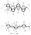
- FIG. 4A and 4B is a smooth knit (also referred to as a double-sided knit or an interlock), in which two milling knits are overlapped to fill in the uneven grooves of each other.
- the knitting structure is composed of a conductive yarn 10 and a stretchable yarn 11. As long as the conductive yarn 10 and the elastic yarn 11 are included, it is optional to mix another type of yarn. If the upper surface side of FIG.
- the conductive yarn 10 is entangled with the conductive yarn old loop 10a on the knitted fabric front side, and the first loop is formed.
- P1 is formed and the fabric moves to the back side of the knitted fabric.
- a second loop P2 is formed by entanglement with the conductive yarn old loop 10b on the back side of the knitted fabric, and thereafter, a third loop P3 is formed on the front side of the knitted fabric, and a fourth loop P4 is formed on the back side of the knitted fabric.
- the conductive yarns 10 are provided in a zigzag arrangement in the direction between the front and back surfaces in the knitted fabric.
- the elastic yarn 11 is entangled with the elastic yarn old loop 11a on the back side of the knitted fabric to form a first loop R1 and moves to the knitted fabric surface side. Then, the second loop R2 is formed by entanglement with the elastic yarn old loop 11b on the surface side of the knitted fabric, and thereafter, the third loop R3 is formed on the back side of the knitted fabric, and the fourth loop R4 is formed on the surface side of the knitted fabric. And so on. Therefore, the stretchable yarn 11 is also provided in a zigzag arrangement in the direction between the front and back surfaces in the knitted fabric. As a result, in the knitted fabric, the cross portions 13 of the conductive yarn 10 and the elastic yarn 11 are formed in an alternate arrangement for each loop.
- the elastic yarn 11 has abundant elasticity, whereas the conductive yarn 10 hardly expands and contracts. Therefore, when the knitted fabric structure is extended along the surface direction of the front and back surfaces (the left-right direction in FIG. 4), the stretchable yarn 11 intersects with the conductive yarn 10 in the cross portion 13, so that the front and back surfaces of the knitted fabric are The cross angle ⁇ generated on the side is gradually increased, and after the obtuse angle, only the elastic yarn 11 gradually expands. Next, a behavior occurs in which the conductive yarn 10 is drawn out from the loop to the cross portion 13 by being pulled by the expansion of the elastic yarn 11.
- the extension when the extension is released, only the elastic yarn 11 generates a tightening force due to the contraction in the cross portion 13, and the conductive yarn 10 is pushed from the cross portion 13 into the loops on both outer sides by receiving the tightening force. .
- the tightening force of the elastic yarn 11 at this time has an effect of maintaining the zigzag arrangement of the conductive yarn 10 in the non-stretchable knitted fabric structure.
- the conductive yarn 10 expands and contracts together with the expansion and contraction of the elastic yarn 11 while not only making the loop smaller or larger by feeding or pushing the loop into the cross portion 13.
- the knitted fabric structure has elasticity as shown in FIG. 4 (b).
- the conductive yarn 10 does not substantially expand and contract, the total length used in the course direction does not change, and the outer diameter of the conductive yarn 10 does not change.
- the conductive yarn 10 does not come into contact with the loops arranged in the course direction, does not become entangled or comes into contact between a plurality of courses, and the electric resistance remains unchanged.
- the first electrode portion 31 is preferably configured to have an electrical resistance per unit length (1 cm) at 0% elongation of 50 ⁇ or less, and more preferably 10 ⁇ or less. . Further, it is even more preferable that the configuration be 5 ⁇ or less.
- the second electrode portion 41 is preferably configured to have an electric resistance per unit length (1 cm) at 0% elongation of 50 ⁇ or less, and more preferably 10 ⁇ or less. preferable. Further, it is even more preferable that the configuration be 5 ⁇ or less.
- the first electrode section 31 may be configured to have stretching anisotropy. That is, the first electrode portion 31 may be configured to have a characteristic that it is easy to extend in the longitudinal direction and hard to extend in the short direction. As described above, when the dimensional change in the short direction of the first electrode unit 31 due to the extension is configured to be smaller than that in the longitudinal direction, when the first electrode unit 31 is extended by 50% in the longitudinal direction, It is preferable that the dimensional change rate in the short direction (change rate with respect to the short direction dimension at 0% elongation) is less than 5%. Such a configuration is obtained, for example, by forming the first electrode portion 31 as a double knitted fabric.
- the double knitted fabric refers to a knitted fabric such as a milling knit, a pearl knit, a smooth knit, or the like. Since the double knitted fabric has a zigzag accordion structure in the thickness direction, the accordion structure effectively suppresses a dimensional change in the short direction of the first electrode portion 31 during expansion and contraction. Similarly, the second electrode portion 41 may be configured to have stretch anisotropy.
- the non-conductive yarn for forming the first non-conductive portion 32 or the second non-conductive portion 42 a synthetic fiber (for example, polyester fiber or nylon fiber), a natural fiber, or a mixture of a synthetic fiber and a stretchable yarn is used. Materials that have been used can be used.
- the elastic yarn By using the elastic yarn, the elasticity of the first non-conductive portion 32 and the second non-conductive portion 42 can be improved.
- a polyurethane or rubber-based elastomer material may be used alone, or a covering yarn using a polyurethane or rubber-based elastomer material for the “core” and nylon or polyester for the “cover”. Etc. can be adopted.
- a covering thread By employing such a covering thread, functions such as hydrophilicity, water repellency, corrosion / corrosion resistance, and coloring can be imparted. It is also useful for improving feel and controlling elongation.
- a monofilament can be used as the non-conductive yarn, a multifilament or a spun yarn, which is an aggregate of a plurality of single fibers, can be more preferably used than a monofilament.
- the first non-conductive portion 32 and the second non-conductive portion 42 are preferably formed of a non-conductive thread having heat resistance to the melting temperature of solder.
- the heat resistance required for the non-conductive yarn forming the first non-conductive portion 32 and the second non-conductive portion 42 is such that the non-conductive yarn is ignited or melted even by contact with molten solder (or a heated iron trowel). No damage and no easy burning.
- the degree of occurrence of scorching is within an allowable range (can be used for forming a non-conductive portion). In other words, a material having sufficient heat resistance so that the form remains even after soldering is sufficient in function.
- the knitting structure of the first non-conductive portion 32 and the second non-conductive portion 42 may be made to have a dense structure. It is even more preferable to take measures.
- the heat resistance required of the first non-conductive portion 32 and the second non-conductive portion 42 is required at a contact position with the first electrode portion 31 and the second electrode portion 41, The entire first non-conductive portion 32 and the second non-conductive portion 42 in the band width direction do not necessarily have to have the same configuration.
- first non-conductive portion 32 heat resistance is provided only in one course or a few courses in contact with the first electrode portion 31, and a course portion that does not directly contact the first electrode portion 31 (the non-conductive portion
- the central portion in the band width direction or the like can be knitted by using a general knitting structure or a general material (a material having no heat resistance to molten solder). The same applies to the second non-conductive portion 42.
- heat-resistant non-conductive yarns that are preferable for forming the first non-conductive portion 32 and the second non-conductive portion 42 include various natural fibers such as cotton and wool, glass fibers, and ceramics. Fiber, carbon fiber, and various other synthetic fibers (eg, aramid fiber, phenol fiber, PBO, polyarylate, polyimide, melamine, PPS, PEEK, PTFE, cellulose fiber (flame retardant), nylon (flame retardant)) , Acrylic fibers, etc.).
- synthetic fibers eg, aramid fiber, phenol fiber, PBO, polyarylate, polyimide, melamine, PPS, PEEK, PTFE, cellulose fiber (flame retardant), nylon (flame retardant)
- Acrylic fibers etc.
- a voltage is applied to each of the first electrode unit 31 and the second electrode unit 41 included in the first conductive layer 3 and the second conductive layer 4, respectively.
- the tension sensor 1 the sensor main body 1a
- the distance between the first electrode unit 31 and the second electrode unit 41 decreases, and the first electrode unit 31 and the second electrode unit 41
- the capacitance during the period increases.
- the extension increases the area of the tension sensor 1, and the capacitance between the first electrode unit 31 and the second electrode unit 41 increases.
- the extension state is released and the tension sensor 1 contracts (a state where the extension rate is 0%)
- the interval between the first electrode portion 31 and the second electrode portion 41 increases, and the tension sensor 1 (the sensor main body 1a).
- the tension sensor 1 the sensor main body 1a
- the deformation of the detection target is detected by the tensile sensor 1
- the detected capacitance increases, it can be detected that the deformation has increased. More specifically, for example, when the tension sensor 1 is attached to the elbow portion or the knee portion of the outerwear worn by a person, the tension sensor 1 is extended and detected by bending of the arm or leg. The value of the capacitance changes greatly.
- the tension sensor 1 (sensor body 1a) is attached to the chest or abdomen of the outerwear worn by a person, or is wound around the chest or the waist, so that the tension sensor 1 (sensor By attaching the main body 1a), the tension sensor 1 expands and contracts based on the physique change due to the breathing action of the wearer. By detecting a change in capacitance due to the expansion and contraction, it is determined whether or not the wearer is breathing. And whether the breathing cycle is fast or slow.
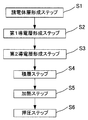
- the manufacturing method of the tension sensor 1 includes a dielectric layer forming step S1, a first conductive layer forming step S2, a second conductive layer forming step S3, a laminating step S4, a heating step S5, And a pressing step S6.
- these steps are described so as to proceed in the order of the dielectric layer forming step S1, the first conductive layer forming step S2, and the second conductive layer forming step S3.
- steps S1 to S3 may be performed in any order as long as the steps are performed in a step before the laminating step 4.
- the dielectric layer forming step S1 may be performed, or the dielectric layer forming step S1, the first conductive layer forming step S2, the second Each step of the conductive layer forming step S3 may be performed simultaneously.
- the dielectric layer forming step S1 includes expansion and contraction including a low melting point resin layer (first low melting point resin layer 22 and second low melting point resin layer 23) provided on both surfaces of the high melting point resin layer 21 and the high melting point resin layer 21, respectively. This is a step of forming the dielectric layer 2 having a property.
- the method of forming the dielectric layer 2 in the dielectric layer forming step S1 is not particularly limited.
- a film-like low melting point resin layer (first low melting point resin layer) 22 and the second low melting point resin layer 23) may be formed by laminating with an adhesive layer interposed therebetween (or by heat lamination without interposing an adhesive layer), or a film-shaped high melting point resin layer 21 may be formed.
- a material for forming the low-melting resin layers 22 and 23 may be coated on both surfaces of the substrate, or may be formed into three layers by extrusion.
- a film-like low-melting resin layer (for example, a first low-melting resin layer 22) is laminated on one surface of the film-like high-melting resin layer 21 with an adhesive layer interposed therebetween. May be formed by applying a material for forming the low-melting-point resin layer 23 on the other surface.
- the first conductive layer forming step S2 and the second conductive layer forming step S3 are steps of forming the first conductive layer 3 and the second conductive layer 4 described above.
- the first electrode section is formed.
- the first conductive layer 3 A step of forming the second conductive layer 4 can be exemplified. Since the method for forming the first conductive layer 3 and the second conductive layer 4 has been described in detail above, the description thereof is omitted here.
- the laminating step S4 includes, on one surface and the other surface of the dielectric layer 2 formed in the dielectric layer forming step S1, a strip-shaped first electrode portion 31 made of the conductive thread formed in the first conductive layer forming step S2.
- a first conductive layer 3 configured as a knitted fabric structure or a woven fabric structure, and a band-shaped second electrode portion 41 formed of the conductive yarn formed in the second conductive layer forming step S3.
- the heating step S5 is a step of heating the low-melting resin layers (the first low-melting resin layer 22 and the second low-melting resin layer 23) to make the low-melting resin layers 22 and 23 flowable.
- the heating temperature in the heating step S5 causes the low-melting resin layers (the first low-melting resin layer 22 and the second low-melting resin layer 23) included in the dielectric layer 2 to be in a flowable state. Is set to a temperature that does not allow the fluid to flow.
- the temperature is set to a temperature at which the low-melting-point resin layer (the first low-melting-point resin layer 22 and the second low-melting-point resin layer 23) is melted, and a temperature at which the high-melting-point resin layer 21 is not melted.
- the temperature may be set to a temperature at which the low-melting resin layers (the first low-melting resin layer 22 and the second low-melting resin layer 23) are allowed to flow without being melted.
- the first conductive layer 3 and the second conductive layer 4 are pressed by a pressing device or the like so as to be close to each other, and are heated so as to be in a flowable state (the first low melting point resin). While the first conductive layer 3 and the second conductive layer 4 are impregnated with the layer 22 and the second low melting point resin layer 23, the first conductive layer 3 (the first electrode portion 31) and the second conductive layer 4 (the second electrode This is a step of reducing the inter-surface distance with the portion 41). The high melting point resin layer 21 included in the dielectric layer 2 is not melted by the heating in the heating step S5 and is kept in a non-flowing state.
- the first conductive layer 3 and the second conductive layer 4 Of the first conductive layer 3 (first electrode part 31) and the second conductive layer 4 (second electrode part) 41) is preferable from the viewpoint of making the distance between the surfaces as small as possible.
- the laminated body composed of the first conductive layer 3, the dielectric layer 2, and the second conductive layer 4 is naturally cooled or the like, so that the low-melting resin layers 22, 23 which have been in a flowable state. Is solidified, the first conductive layer 3 and the second conductive layer 4 are firmly fixed to the dielectric layer 2, and the tensile sensor 1 is completed.
- the heating step S5 and the pressing step S6 may be simultaneously performed using a heat press method.
- the tension sensor 1 has a capacitance based on a change in the area of the tension sensor 1 in addition to a change in the interval between the first electrode portion 31 and the second electrode portion 41 caused by extension and contraction. Is configured to be able to detect the change in the capacitance, it is possible to improve the detection sensitivity for the change in the capacitance. Further, since the dielectric layer 2 having elasticity is provided between the first conductive layer 3 and the second conductive layer 4, the state from the stretched state to the state before the stretch (state in which the stretch ratio is 0%) In addition to the characteristic that the elasticity is easy to return to, the elasticity is less likely to be impaired even if the expansion and contraction are repeated while the use is continued. Further, since the dielectric layer 2 is interposed, the first conductive layer 3 and the second conductive layer are so large that the conductive yarn forming the first electrode portion 31 and the second electrode portion 41 is broken. 4 can be effectively suppressed from exceeding the limit.
- the dielectric layer 2 includes a sheet-like high melting point resin layer 21 and sheet-like first low melting point resin layers 22 and second low melting point resin layers 22 respectively provided on both surfaces of the high melting point resin layer 21.
- the first low-melting resin layer 22 and the second low-melting resin layer which are melted and flowable by the heating step S5 and the pressing step S6 in the manufacturing process because they are configured to include the melting point resin layer 23.
- 23 is impregnated and solidified in the fabric of the first conductive layer 3 and the second conductive layer 4 (gap between stitches and fibers), so that the first conductive layer 3 and the second conductive layer 4 are firmly made of a dielectric material. It will be fixed to layer 2.
- the high melting point resin layer 21 in the dielectric layer 2 is maintained at a predetermined thickness (for example, 5 ⁇ m to 100 ⁇ m) without melting, a part of the first electrode portion 31 in the first conductive layer 3 and the second It is possible to reliably prevent a short circuit between the conductive layer 4 and a part of the second electrode portion 41 via the dielectric layer 2 (the high melting point resin layer 21).
- the first conductive layer 3 and the second conductive layer 4 are configured as a knitted or woven fabric (woven fabric) using a conductive yarn and a non-conductive yarn as in the present embodiment.
- the fluffed portion of the fabric is generated, and the fluffed portion may penetrate through the dielectric layer 2 at the time of the pressing step S6.
- the body layer 2 By configuring the body layer 2, it is possible to reliably prevent the fluffing portion from penetrating.
- the first electrode portion 31 of the first conductive layer 3 and the second electrode portion 41 of the second conductive layer 4 have substantially the same height as that of the dielectric layer 2.
- the thickness of the melting point resin layer 21 (actually, the sum of the thickness of the high melting point resin layer 21 and the small thickness of the first low melting point resin layer 22 and the second low melting point resin layer 23) It is possible to arrange the first electrode part 31 and the electrode part 41 in a very close state. As a result, a change in capacitance between the first conductive layer 3 and the second conductive layer 4 due to expansion and contraction of the tension sensor 1 can be detected with high sensitivity. When detecting deformation or the like of the detection target, it is possible to reduce the ratio of the noise signal mixed into the detection signal when any other dielectric comes close to the tension sensor 1, and is less susceptible to noise. A highly accurate tension sensor 1 can be obtained.
- the high melting point resin layer 21 is made of a resin material having a melting point higher by 40 ° C. or more than the melting points of the first low melting point resin layer 22 and the second low melting point resin layer 23 included in the dielectric layer 2, Even if the heating temperature in the heating step S5 becomes higher than the set temperature due to some influence, it is possible to effectively prevent a situation in which the high melting point resin layer 21 is melted.
- the resistance change rate of the first electrode portion 31 at the time of 50% elongation is configured to be 20% or less, and similarly, the second electrode portion 41 at the time of 50% elongation.
- the resistance change rate is configured to be 20% or less, it is possible to accurately detect a change in the detected capacitance.
- the first electrode portion 31 is configured so that the electric resistance per unit length (1 cm) is 50 ⁇ or less, and similarly, the electric resistance per unit length (1 cm) of the second electrode portion 41 is When the configuration is set to be 50 ⁇ or less, it is possible to more accurately detect the change in the detected capacitance.
- the first electrode portion 31 and the second electrode portion 41 are configured to have a knitted fabric structure, the first electrode portion 31 and the second electrode portion 41 are formed by the extension of the tension sensor 1. It becomes possible to make the structure in which the yarn is difficult to break.
- the first electrode portion 31 and the second electrode portion 41 configured to have a knitted fabric structure are, for example, milled knit, pearl knitted, and smoother than those formed by a single knitted fabric such as a flat knitted fabric.
- a double knitted fabric such as a knit
- a zigzag accordion structure is formed in the thickness direction, so that a dimensional change in the short direction of the first electrode portion 31 and the second electrode portion 41 is effectively suppressed, and the first electrode accompanying extension is formed.
- the area increase ratio of the portion 31 and the second electrode portion 41 substantially constant, so that a change in capacitance can be detected with high accuracy.
- the tension sensor 1 may be configured to include an elastic base cloth 5 that is stacked and disposed on one surface side of the sensor main body 1a.
- the sensor main body 1a may be attached to the elastic base cloth 5 via an adhesive layer, or the sensor main body 1a may be sewn onto the elastic base cloth 5 by sewing and fixed. May be.
- the stretchable base fabric 5 is not particularly limited, and examples thereof include stretchable fabrics formed of woven rubber, such as waistbands, supporters, and T-shirts.
- the stretchable base cloth 5 may be configured to have stretch anisotropy.
- the elastic base cloth 5 is configured to have elastic anisotropy
- the tensile sensor 1 as a whole exhibits the characteristic of elastic anisotropy even when the sensor body 1a has a structure without elastic anisotropy. This makes it possible to detect a change in capacitance with high accuracy and high sensitivity to expansion and contraction.
- the first conductive layer 3 or the second conductive layer 4 and the stretchable base cloth 4 are arranged such that the first conductive layer 3 or the second conductive layer 4 included in the sensor main body 1 a forms a part of the stretchable base cloth 5.
- 5 can be integrated. More specifically, for example, when knitting the elastic base cloth 5 as a woven rubber structure, the first conductive layer 3 or the second conductive layer 4 is also incorporated and knitted, so that the first conductive layer 3 is knitted. Or you may comprise so that the 2nd conductive layer 4 and the elastic base fabric 5 may be integrated.
- the elastic base cloth 5 is formed in a cylindrical shape, and the sensor body 1a is arranged in the circumferential direction of the elastic base cloth 5 whose longitudinal direction is cylindrical.
- the tension sensor 1 may be configured by laminating and arranging them so as to be along the direction.
- the sensor main body 1 a is laminated on such a tubular elastic base cloth 5, the sensor main body 1 a is further provided with a band-like elastic adjustment layer 6 arranged along the circumferential direction of the tubular elastic base cloth 5. You can also.
- one end of the expansion and contraction adjustment layer 6 is arranged at least near one end of the sensor main body 1a, and the other end of the expansion and contraction adjustment layer 6 is arranged at least near the other end of the sensor main body 1a.
- one end of the expansion / contraction adjustment layer 6 is connected to one end of the elongated sensor main body 1a, and the other end of the expansion / contraction adjustment layer 6 is connected to the other end of the sensor main body 1a. It is configured to By providing such an elasticity adjusting layer 6, the sensor main body 1a and the elasticity adjusting layer 6 constitute an integrated structure, and an annular structure is formed on the tubular elastic base cloth 5.
- the expansion / contraction adjustment layer 6 is preferably formed so as to include the same material as the above-described high melting point resin layer 21, and is more preferably formed from the same material as the high melting point resin layer 21. Further, it is preferable that the thickness dimension of the expansion / contraction adjustment layer 6 is also configured to be equal to the thickness dimension of the high melting point resin layer 21.
- the tension sensor 1 having a structure in which the sensor main body 1a is merely laminated on the tubular elastic base cloth 5 is wound around the chest and waist of the human body.
- the portion 5a (the area other than the sensor body 1a) not functioning as a sensor greatly expands and contracts due to the physique change caused by the breathing motion.
- the sensor main body 1a itself is less likely to expand and contract, and may not be able to efficiently detect respiratory cycle information.
- FIG. 7 (b) the tension sensor 1 having a structure in which the sensor main body 1a is merely laminated on the tubular elastic base cloth 5 is wound around the chest and waist of the human body.
- the elastic adjustment layer 6 is arranged on the portion 5a of the elastic base cloth 5 which does not function as a sensor, and the sensor main body 1a and the elastic adjustment layer 6 are integrated.
- the sensor body 1a also greatly expands and contracts with the physique change due to the respiratory action, so that the change in the capacitance with the physique change can be detected with high accuracy and high sensitivity. Respiratory cycle information and the like can be detected efficiently.
- one end of the expansion / contraction adjustment layer 6 is necessarily connected to one end of the sensor main body 1a. It is not necessary to configure the other end of the layer 6 to be connected to the other end of the sensor body 1a.
- one end of the expansion / contraction adjustment layer 6 is arranged at a position where a gap is formed between the one end of the sensor body 1a.
- the other end of the expansion / contraction adjustment layer 6 may be arranged at a position where a gap is formed between the other end of the sensor main body 1a.
- the band-shaped expansion / contraction adjustment layer 6 may be formed of the same material over the entire area in the longitudinal direction, or may be formed of a partially different material. Further, as the structure of the expansion / contraction adjustment layer 6, for example, a predetermined region near one end of the sensor main body 1a and a predetermined region near the other end are configured as stretchable portions, and a portion hardly stretches between the stretchable portions. May be arranged.
- the first electrode portion 31 and the second electrode portion 41 are arranged along the longitudinal direction of the strip-shaped tension sensor 1 (sensor body 1a) as shown in FIGS.
- the first electrode portion 31 and the second electrode portion 41 are not particularly limited in specific form. For example, along a longitudinal direction of the tension sensor 1 in a plan view. It can be configured in various forms such as a stretched corrugated shape or a zigzag shape.
- the first conductive layer 3 is configured to include the first non-conductive portion 32. However, the first non-conductive portion 32 is omitted, and the first non-conductive portion 32 is omitted.
- One conductive layer 3 may be configured.
- the second conductive layer 4 may be constituted only by the second electrode portion 41.
- a coating layer may be provided to cover the surface of the exposed surface (the surface not in contact with the dielectric layer 2) of the first conductive layer 3 or the second conductive layer 4.
- the first electrode portion 31 and the second electrode portion 41 can be protected, and the durability of the tension sensor 1 can be improved.
- the coating layer may be provided only on one of the first conductive layer 3 side and the second conductive layer 4 side.
- a material for forming the coating layer for example, the above-described material for forming the dielectric layer 2 can be used.
- the first conductive layer 3 and the second conductive layer 4 are each provided with a single first electrode portion 31 and a plurality of second electrode portions 41 as shown in FIG.
- the number of the first electrode portions 31 and the second electrode portions 41 is not particularly limited.
- the tension sensor 1 may be configured such that a plurality of first electrode portions 31 and a plurality of second electrode portions 41 are provided on both sides thereof.
- the first electrode portions 31 are arranged so as to be parallel to each other at a predetermined interval, and similarly, the second electrode portions 41 are also parallel to each other at a predetermined interval from each other. It is arranged to become.
- FIG. 8A is a schematic configuration plan view of the tension sensor 1
- FIG. 8B is a schematic configuration cross-sectional view taken along the line A'-A 'in FIG. 8A.
- FIG. 8C is a schematic configuration rear view.
- each of the first electrode portions 31 is short-circuited, and each of the first electrode portions 31 is short-circuited.
- the other end of the one electrode portion 31 may be short-circuited.
- each of the second electrode portions 41 is formed in order to form an aggregate of the plurality of second electrode portions 41 as one electrode. And the other end of each first electrode portion 31 may be short-circuited.
- each combination of the first electrode unit 31 and the second electrode unit 41 opposed to each other with the dielectric layer 2 interposed therebetween (the first electrode unit 31a and the second electrode unit 41a).
- the combination of the first electrode portion 31b and the second electrode portion 41b, and the combination of the first electrode portion 31c and the second electrode portion 41c) may be configured as independent capacitors.
- the tension sensor 1 sensor main body 1a
- the tension sensor 1 can detect not only the tension in the longitudinal direction but also the torsion around the longitudinal direction. More specifically, when a torsion is applied to the tension sensor 1 (sensor body 1a) with its longitudinal direction as an axis, the center of the tension sensor 1 (sensor body 1a) is larger than the side edges.
- the value of the capacitance change detected by the capacitor composed of the first electrode portion 31b and the second electrode portion 41b disposed at the center and the first electrode portion 31a disposed at the side edge portion A difference occurs between the value of the capacitance change detected by the capacitor constituted by (31c) and the second electrode portion 41a (41c). By detecting this difference, it is possible to determine whether or not torsion has been applied to the tension sensor 1 (sensor main body 1a).
- the first electrode portion 31 and the second electrode portion 41 are configured to have the same width (dimension in a direction perpendicular to the longitudinal direction), but such a configuration is adopted. Is not particularly limited.
- the width of the second electrode portion 41 is made larger than the width of the first electrode portion 31 so that the area of the second electrode portion 41 in plan view becomes
- the first electrode unit 31 may be configured to have a larger area than the one electrode unit 31, and the second electrode unit 41 may be disposed at a position facing the first electrode unit 31 via the dielectric layer 2.
- the first electrode unit 31 when the first electrode unit 31 is virtually projected onto the second conductive layer 4, the first electrode unit 31 is arranged such that the first electrode unit 31 is disposed in the second electrode unit 41 formation region.
- the second electrode portion 41 may be configured.
- the first conductive layer 3 and the second conductive layer 4 are arranged so that the first electrode section 31 and the second electrode section 41 are opposed to each other with the dielectric layer 2 interposed therebetween.
- the area of the second electrode portion 41 is configured to be larger than the area of the first electrode portion 31 as shown in FIG. It is not necessary to strictly align the first conductive layer 3 and the second conductive layer 4 with respect to the above, and the tensile sensor 1 (sensor body 1a) can be manufactured efficiently.
- the second electrode portion 41 is configured to have an area larger than the area, and the second electrode portion 41 is located at a position facing the region where the plurality of first electrode portions 31 are arranged via the dielectric layer 2. You may comprise so that it may be arrange
- the first electrode unit 31 and the second electrode unit 41 may be configured.
- the second electrode portion 41 is shielded.
- the first conductive layer 3 and the second conductive layer 3 are arranged such that each first electrode section 31 and each second electrode section 41 face each other with the dielectric layer 2 interposed therebetween.
- the configuration is such that the area of the second electrode portion 41 in a plan view is larger than the area of the region where the plurality of first electrode portions 31 are arranged.
- the inventor of the present invention prepared a sample A of the tensile sensor 1 (sensor main body 1a) according to the present invention and a sample B corresponding to the comparative example, and evaluated the performance when actually extending the sample. This will be described below.
- the sample A has the tension sensor 1 having a structure in which the sensor main body 1 a is laminated on one surface of the elastic base cloth 5. Further, the upper first conductive layer 3 provided in the sensor main body 1a is formed only by the first electrode portion 31, and similarly, the second conductive layer 4 disposed below the sensor main body 1a is formed only by the second electrode portion 41. It is formed by.
- the first conductive layer 3 (first electrode portion 31) has a rectangular shape in plan view having a width of 5 mm and a length of 145 mm, and the second conductive layer 4 (second electrode portion 41) has a width of 5 mm. It has an elongated rectangular shape in a plan view with a length of 8.5 mm and a length of 145 mm.
- Each of the first conductive layer 3 (the first electrode portion 31) and the second conductive layer 4 (the second electrode portion 41) is configured such that its structure has a milling structure. More specifically, it has a bare milling structure, and is formed by adding and knitting silver-plated fiber yarn and bare polyurethane fiber yarn. After knitting, the knitted fabric is subjected to a heat setting process performed in a manufacturing stage, and after intersections of the bare polyurethane fiber yarns are welded or coalesced to prevent fraying, cut to a predetermined size, and the sample is cut. A first conductive layer 3 and a second conductive layer 4 are formed.
- a polyurethane film having a melting point of 120 ° C. and a thickness of 50 ⁇ m was provided on both sides of a polyurethane film having a melting point of 200 ° C. and a thickness of 50 ⁇ m (high-melting resin layer 21).
- a film sheet formed by lamination is used as the dielectric layer 2, and the first conductive layer 3 and the second conductive layer 4 are laminated on both sides of the film sheet (dielectric layer 2). It was formed by heat-pressing at 180 ° C. to impregnate the kneaded structure of the first conductive layer 3 and the second conductive layer 4 with the low-melting-point resin layer which became in a flowable state by heating.
- FIG. As shown in the schematic plan view of (1), the installation position of the second conductive layer 4 with respect to the first conductive layer 3 is shifted by 15 mm in the longitudinal direction, and the first conductive layer 3 and the second conductive layer 4 are stacked. Were formed without overlapping, and this portion was used as an electrode terminal.
- the elastic base cloth 5 employs an elastic cloth generally used for a supporter or the like.
- the elastic base cloth 5 has a thickness of 1 mm, a width of 20 mm and a length of 330 mm, and is formed in a rectangular shape in plan view.
- the elastic base cloth 5 and the sensor main body 1a are fixed via an adhesive layer.
- the sample B has the same structure as the sample A with respect to the first conductive layer 3, the second conductive layer 4, and the stretchable base cloth 5, but only the specific configuration of the dielectric layer 2 is different.
- the dielectric layer 2 a polyurethane film having a melting point of 120 ° C. and a thickness of 150 ⁇ m was used, and both sides of the polyurethane film (dielectric layer 2) in the above-described sample A were used.
- heat pressing is performed at a bonding temperature of 180 ° C. to convert the first conductive layer 3 and the second conductive layer 4 to a polyurethane film (dielectric layer 2). And then fixed on the stretchable base fabric 5 via an adhesive layer (see the schematic configuration sectional view of FIG. 11C).
- Table 1 and FIG. 12 show the relationship between the elongation rate of the sample A according to the tensile sensor 1 and the detected capacitance value.
- the values of the capacitance shown in Table 1 are the average values of the measurement results performed three times.
- the elongation percentage of 0% means a state where the elongation is not performed.
- the first conductive layer 3 (the first electrode portion 31) and the second conductive layer 4 (the second electrode portion 41) disposed on both surfaces of the dielectric layer partially overlap the dielectric layer. Short-circuit, and a change in capacitance could not be detected.
- the cause of the short circuit is that, when the first conductive layer 3 and the second conductive layer 4 are heat-pressed, the fuzzing portions generated on the surface of the conductive yarn forming the first electrode portion or the second electrode portion are This is considered to be due to a state in which the polyurethane film (dielectric layer: melting point: 120 ° C., thickness: 150 ⁇ m), which became flowable by heating, penetrated and came into contact with the second electrode portion or the first electrode portion.
- the inventor also conducted a test to confirm that the tension sensor 1 according to the present invention has characteristics that are hardly affected by noise.
- the test contents and test results will be described.
- the sample A described above and a sample C corresponding to a comparative example were prepared.
- the sample C is configured such that the first conductive layer 3 and the second conductive layer 4 are respectively adhered to both surfaces of the elastic base cloth 5.
- the respective structures of the elastic base cloth 5, the first conductive layer 3 and the second conductive layer 4 in Sample C are the same as those in Sample A.
- a metal plate (aluminum 2 mm thick, 35 mm wide, 310 mm long) was brought close to a position where the distance from the first conductive layer 3 was 15 mm with respect to the sample A and the sample C without being stretched. Then, the change in the capacitance value was measured. Table 3 shows the results.
- the change amount of the capacitance value (corresponding to a noise signal) due to the proximity of the metal plate is “ ⁇ 0.4 pF” in the case of the sample A according to the present invention, and the sample according to the comparative example.
- the noise signal is "-0.6 pF", which indicates that substantially equal noise signals are mixed.
- the change amount of the capacitance value when the metal plate is approached and the change amount at 20% elongation Is in the same order (digit) and it can be seen that it is difficult to accurately detect the capacitance due to the great influence of the proximity of the metal plate.
- the capacitance value increases by “0.4 pF” due to the 20% elongation
- the metal plate or the like cannot be evaluated.
- the capacitance value decreases by “0.6 pF”, and the detected capacitance value does not elongate even though the tension sensor is extended by 20%. The value indicates the state, and the expanded state cannot be detected.
- the sample A is a tensile sensor having a sufficient S / N ratio.
- the S / N ratio is a ratio of a signal ⁇ (signal) ⁇ to a noise (noise), and is an abbreviation of a signal-to-noise ratio ⁇ (signal-noise ratio) ⁇ or ⁇ signal-to-noise ratio ⁇ . I do.
- the tension sensor 1 according to the present invention when installed on a detection target and detects deformation or the like of the detection target, even if any other dielectric or conductor approaches the tension sensor 1 In addition, it is possible to reduce the ratio of the noise signal mixed into the detection signal, and it can be said that the sensor is a high-accuracy sensor that is less affected by noise.
Landscapes
- Physics & Mathematics (AREA)
- General Physics & Mathematics (AREA)
- Force Measurement Appropriate To Specific Purposes (AREA)
- Laminated Bodies (AREA)
- Measurement Of Length, Angles, Or The Like Using Electric Or Magnetic Means (AREA)
Abstract
使用を継続しても検出精度が低下しにくく、また、ノイズの影響を受けにくい高精度な引張センサ、及び、その製造方法を提供する。 伸縮性を有する誘電体層と、前記誘電体層の一方面及び他方面のそれぞれに設けられる伸縮性を有する第1導電層及び第2導電層とを有する短冊状のセンサ本体を備えており、前記第1導電層は、導電性糸から形成される帯状の第1電極部を備え、前記誘電体層は、高融点樹脂層と、前記高融点樹脂層の両面上にそれぞれ設けられる第1低融点樹脂層及び第2低融点樹脂層とを備え、前記第1電極部は、前記第1低融点樹脂層の少なくとも一部が含浸されて配置されており、伸縮に伴う前記第1導電層と前記第2導電層との間における静電容量変化を検出可能な引張センサ。
Description
本発明は、引張センサ及びその製造方法に関する。
従来から検知対象物に取り付け、当該検知対象物の伸び等の動きを検出する引張センサが多種多様に知られており、近年、特許文献1に開示されているように、導電性の繊維と非導電性の繊維を混ぜ合わせた混紡糸から成る編物又は織物として構成される引張センサが開発されつつある。
特許文献1に開示の引張センサは、複数の導電糸を含んで構成された編物又は織物を一方向に伸縮自在にすると共に、絶縁状態が維持されるように構成される導電糸同士の伸縮に伴う間隔変化から静電容量の変化を検出しようとするものである。このような引張センサによれば、編物又は織物の伸縮を静電容量として検出するため、導電糸に電圧は印加されても電流は流れず、この部分での消費電力はゼロとすることができ、消費電力を抑制することができる。
しかしながら、上述の特許文献1に開示されている引張センサは、織物や編物としてのみ構成されるものであることから、使用を継続して伸縮を繰り返すことによりその伸縮性が損なわれやすく、長期にわたって精度良く、検知対象物の変形状態や、作用する引張力の有無、当該引張力の値を検出することが難しいという問題があった。
また、例えば、検知対象に引張センサを設置して該検知対象の変形等を検知する際に、該引張センサに他の何らかの誘電体または導体が近接すると、その誘電体または導体の近接に基づくノイズ信号が、本来取得したい検知対象の変形等に関する信号に混入してしまい、高精度で検知対象物の伸び等の動きを検出することが難しいという問題もあった。
本発明は、このような問題を解決するためになされたものであって、使用を継続しても検出精度が低下しにくく、また、ノイズの影響を受けにくい高精度な引張センサ、及び、その製造方法を提供することを目的とする。
本発明の上記目的は、伸縮性を有する誘電体層と、前記誘電体層の一方面及び他方面のそれぞれに設けられる伸縮性を有する第1導電層及び第2導電層とを有する短冊状のセンサ本体を備えており、前記第1導電層は、導電性糸から形成される帯状の第1電極部を備え、前記誘電体層は、高融点樹脂層と、前記高融点樹脂層の両面上にそれぞれ設けられる第1低融点樹脂層及び第2低融点樹脂層とを備え、前記第1電極部は、前記第1低融点樹脂層の少なくとも一部が含浸されて配置されており、伸縮に伴う前記第1導電層と前記第2導電層との間における静電容量変化を検出可能な引張センサにより達成される。
この引張センサにおいて、前記高融点樹脂層の融点は、前記第1低融点樹脂層及び前記第2低融点樹脂層の融点よりも40℃以上高いことが好ましい。
また、前記第2導電層は、導電性糸から形成される帯状の第2電極部を備えており、前記第2電極部は、前記誘電体層を介して前記第1電極部に対向する位置において、前記第2低融点樹脂層の少なくとも一部が含浸されて配置されていることが好ましい。
また、前記センサ本体の一方面側が積層配置される伸縮性基布を備え、前記伸縮性基布が、伸縮異方性を有するように構成してもよい。
また、前記センサ本体の一方面側が積層配置される筒状の伸縮性基布を備えており、前記センサ本体は、その長手方向が、前記筒状の伸縮性基布の周方向に沿う方向に配置されており、前記筒状の伸縮性基布の周方向に沿って配置される帯状の伸縮調整層を更に備え、前記伸縮調整層の一方端は、少なくとも前記センサ本体の一方端の近傍に配置されており、前記伸縮調整層の他方端は、少なくとも前記センサ本体の他方端の近傍に配置されており前記センサ本体及び前記伸縮調整層は、筒状の伸縮性基布上に環状の構造を構成するようにしてもよい。
また、前記伸縮調整層は、前記高融点樹脂層と同一の材料を含んで形成されていることが好ましい。
また、本発明の上記目的は、高融点樹脂層及び前記高融点樹脂層の両面上にそれぞれ設けられる低融点樹脂層を備える伸縮性を有する誘電体層の一方面及び他方面に、導電性糸から形成される帯状の第1電極部を備え編地構造又は織地構造として構成される第1導電層と、導電性糸から形成される帯状の第2電極部を備え編地構造又は織地構造として構成される第2導電層とをそれぞれ配置する積層ステップと、前記低融点樹脂層を加熱して流動可能状態とする加熱ステップと、前記第1導電層及び前記第2導電層を互いに近接するように押圧して、流動可能状態の前記低融点樹脂層を前記第1導電層及び前記第2導電層に含浸させつつ、前記第1電極部と前記第2電極部との面間距離を狭める押圧ステップとを備える引張センサの製造方法により達成される。
また、この引張センサの製造方法において、押圧ステップは、前記前記第1導電層及び第2導電層を、非流動状態の前記高融点樹脂層を介して当て止めすることが好ましい。
本発明によれば、使用を継続しても検出精度が低下しにくく、また、ノイズの影響を受けにくい高精度な引張センサ、及び、その製造方法を提供することができる。
以下、本発明の実施形態にかかる引張センサについて、添付図面を参照して説明する。なお、図面においては、構成の理解を容易ならしめるために部分的に拡大・縮小している。図1(a)は、本発明に係る引張センサ1が備えるセンサ本体1aの概略構成平面図であり、図1(b)は、その概略構成裏面図である。また、図2は、図1(a)のA-A断面を示す概略構成断面図である。本発明に係る引張センサ1が備えるセンサ本体1aは、例えば、生体の呼吸情報(例えば、呼吸の有無、呼吸サイクル等)や体動情報(例えば、四肢の動作に関する情報)を取得するセンサを構成するものであり、物体の変形を検知する歪センサとして利用可能なセンサである。このセンサ本体1aは、図1や図2に示すように、平面視短冊状の形態を有しており、誘電体層2と、当該誘電体層2の一方面及び他方面のそれぞれに設けられる第1導電層3及び第2導電層4を備えている。このセンサ本体1aは、誘電体層2と、当該誘電体層2を間に挟んだ第1導電層3及び第2導電層4とによりコンデンサを構成するものであり、伸縮に伴う第1導電層3と第2導電層4との間における容量変化を検出可能なセンサである。
誘電体層2は、伸縮性を有するように構成されており、図3の断面図に示すように、シート状の高融点樹脂層21と、該高融点樹脂層21の両面上にそれぞれ設けられるシート状の第1低融点樹脂層22及び第2低融点樹脂層23とを備えるように構成されている。また、この誘電体層2は、第1導電層3及び第2導電層4が積層された状態であってもそれらを通電させることのない絶縁性を備えるように構成されている。誘電体層2の電気抵抗率は、106Ω・cm以上、1018Ω・cm以下であることが好ましい。
また、高融点樹脂層21の材料としては、熱可塑性エラストマーを例示することができる。特に、ウレタンゴム、天然ゴム、イソプレンゴム、ブタジエンゴム、スチレン・ブタジエンゴム、ブチルゴム、ニトリルゴム、エチレン・プロピレンゴム、クロロプレンゴム、アクリルゴム、クロロスルホン化ポリエチレンゴム、シリコーンゴム、フッ素ゴム、エチレン・酢酸ビニルゴム、エピクロロヒドリンゴムの如くの各種ゴム材料が挙げられる。また、上記材料に添加剤を加えてもよい。例えば、誘電率調整、柔らかくする可塑剤、伸びやすくする添加剤等が挙げられる。なお、添加剤は誘電体層2を絶縁破壊しない材料を選択する必要がある。また、高融点樹脂層21は、その融点が150°以上のものを好適に使用することができ、180℃以上の融点を有するものがより好ましく、更には200°以上の融点を有するものがより好ましい。
第1及び第2低融点樹脂層22.23の材料としては、上記高融点樹脂層21の材料において例示したものを使用することができる。また、第1及び第2低融点樹脂層22.23は、その融点が110°以上のものを好適に使用することができ、120°以上のものがより好ましい。ここで、第1及び第2低融点樹脂層22,23、並びに、高融点樹脂層21としては、例えば、共にポリウレタンゴムから形成するというように、同一カテゴリーに含まれる熱可塑性エラストマーを用いて形成することができる。また、高融点樹脂層21としては、その融点が、第1及び第2低融点樹脂層22,23の融点よりも40℃以上高いものを使用することが好ましい。また、より好ましくは、60℃以上高いものを、更に好ましくは80℃以上高いものを使用するのがよい。
また、高融点樹脂層21を形成する材料として、例えば、高融点の発泡ウレタンゴムを採用し、内部に微小な空隙を備えるスポンジ状として誘電体層2を構成してもよい。このようなスポンジ状に構成することにより、引っ張り状態が解放された際に、誘電体層2が初期形態(伸長する前の形態)に戻り易くすることができる。
ここで、高融点樹脂層21の厚みは、特に限定されないが、5μm~100μmの範囲に設定することが好ましく、10μm~75μmの範囲に設定することがより好ましい。更に、20μm~60μmの範囲に設定することがより好ましい。また、第1低融点樹脂層22及び第2低融点樹脂層23の厚みも特に限定されないが、上記の高融点樹脂層21の厚みと同程度の厚みを有するように構成することが好ましい。
第1導電層3は、図1や図2に示すように、帯状の第1電極部31を備えると共に、第1電極部31の両側に帯状の第1非導電部32を備えて構成されている。第2導電層4は、第1導電層3と同一の構成を有しており、帯状の第2電極部41を備えると共に、第2電極部41の両側に帯状の第2非導電部42を備えて構成されている。なお、第1導電層3が有する第1電極部31及び第1非導電部32の長手方向や、第2導電層4が有する第2電極部41や第2非導電部42の長手方向は、短冊状のセンサ本体の長手方向に沿う方向となるように設定している。また、短冊状のセンサ本体の伸長方向は特に限定されないが、センサ本体の長手方向に沿って伸長可能となるように構成してもよい。
これら第1導電層3及び第2導電層4の一方面側は、図2に示すように、誘電体層2が備える第1低融点樹脂層22及び第2低融点樹脂層23に埋設された状態で配設されている。つまり、第1電極部31は、第1低融点樹脂層22の少なくとも一部が含浸された状態で配置されており、第2電極部41は、第2低融点樹脂層23の少なくとも一部が含浸された状態で配置されている。このような配置関係であるため、第1導電層3及び第2導電層4は、実質的に、誘電体層2が備える高融点樹脂層21を介した両面側にそれぞれ対向配置される構造を有することになる。
また、第1導電層3は、伸縮性を有するように構成されており、例えば、第1電極部31を構成するための導電性糸と、各第1非導電部32を構成するための非導電性糸とを用いて製編或いは製織された生地(編織された生地)として構成することが好ましい。第2導電層4についても同様であり、第2電極部41を構成するための導電性糸と、各第2非導電部42を構成するための非導電性糸とを用いて製編或いは製織された生地として構成することが好ましい。本実施形態においては、編成することにより構成された編地構造を有する生地として第1導電層3(第1電極部31及び第1非導電部32)及び第2導電層4(第2電極部41及び第2非導電部42)が形成されている。なお、編地構造は特に限定されず、例えば、フライス編、スムース編、パール編、平編又はそれらの変化組織(例えば、ミラノリブや段ボールニットなど)や、トリコット編、ラッシェル編、ミラニーズ編等の各種編地構造を採用することができる。また、第1導電層3及び第2導電層4を織地として構成する場合、織地構造としては、平織、綾織、朱子織等の織り方を例示できる。なお、第1導電層3及び第2導電層4の製造方法は、上記方法に限定されず、例えば、非導電繊維によってまず生地本体を製編或いは製織した後、所定部分に導電性糸を編み込み、或いは、刺繍等して第1電極部31(或い第2電極部41)を形成し製造することもできる。
ここで、第1電極部31や第2電極部41を構成するための導電性糸としては、例えば、合成繊維(例えば、ポリエステル繊維やナイロン繊維等)や天然繊維等を芯として、この芯に湿式や乾式のコーティング、メッキ、真空成膜、その他の適宜被着法を行って金属成分を被着させた金属被着糸(メッキ糸)を使用することができる。芯には、モノフィラメントを採用することも可能ではあるが、モノフィラメントよりも、複数の単繊維の集合体であるマルチフィラメントや紡績糸のほうが好ましく、更にはウーリー加工糸やSCY、DCYなどのカバリング糸、毛羽加工糸などの嵩高加工糸がより好ましい。芯に被着させる金属成分には、例えばアルミ、ニッケル、銅、チタン、マグネシウム、錫、亜鉛、鉄、銀、金、白金、バナジウム、モリブデン、タングステン、コバルト等の純金属やそれらの合金、ステンレス、真鍮等を使用することができる。また、導電性糸としては、例えば、アルミ、ニッケル、銅、チタン、マグネシウム、錫、亜鉛、鉄、銀、金、白金、バナジウム、モリブデン、タングステン、コバルト等の純金属やそれらの合金、ステンレス、真鍮等により形成された糸状或いは細短冊状の金属線や、炭素繊維等の導電性繊維から形成した糸を使用することができる。また、合成繊維や天然繊維等を芯として、この芯に金属繊維を巻回したカバリングヤーンを導電性糸として使用してもよい。
導電性糸の太さは、特に限定されるものではないが、その単線一本あたりの線径は、例えば、10~100μmのものとするのが好適である。中でも10~50μmとすることで、第1導電層3や第2導電層4自体(第1電極部31や第2電極部41自体)のフレキシブル性と耐久性が両立しやすく、特に好ましい。
また、導電性糸として金属線を用いる場合、絶縁被覆層によりその表面を被覆してもよい。絶縁被覆層により被覆された金属線は、モノフィラメントでもよいし、マルチフィラメントでもよく、特に2~9本、より好ましくは3~7本を束ねて1本の糸条として用いるのが好ましい。このように絶縁被覆層によって金属線を被覆することにより、引張センサ1が伸縮する際の抵抗変化が小さくなり、伸縮に伴う容量変化を精度よく検出することが可能となる。また、防水性、耐久性が向上し、長期間使用可能な引張センサ1を得ることができる。
絶縁被覆層として使用可能な材料の具体名を挙げれば枚挙に暇がないが、その一例を列挙すれば次の通りである。すなわち、ポリウレタン、ポリ塩化ビニル、ポリプロピレン、ポリエチレン、ナイロン(ナイロン6やナイロン66等であって、アミド結合により長く連続した鎖状の合成高分子を紡糸して繊維化したポリアミド系の合成繊維の総称)、ポリエステル、ポリエチレンテレフタレート、ポリブチレンテレフタレート、ポリフェニレンサルファイド、ポリエーテルエーテルケトン、PFA、PVDF、ETFE等のフッ素系樹脂、ポリスチレン、ポリカーボネイト、ポリスルフォン、ポリエーテルスルフォン、ホルマール(ポリビニルホルマール)、ブチラール(ポリビニルブチラール)などである。なお、絶縁被覆層として使用可能な材料は、これらの樹脂種に限定されない。また、例示したような樹脂で絶縁コーティングした金属線はエナメル被覆の金属線とも呼ばれる。
絶縁被覆層で金属線を被覆する方法としては、溶融素材の塗布から乾燥に至る一般的な被覆法を採用すればよい。その他、金属線を芯材とし、繊維状(糸状)の絶縁被覆材(例えば、上記の絶縁被覆層として使用可能な材料から形成した糸や綿糸)をカバー材としてカバリング糸(SCYやDCY)を構成させる方法、さらには前記カバリング糸を加熱溶融して塗膜化する方法などを採用することも可能である。
また、絶縁被覆層により被覆された導電性糸において、絶縁被覆層を形成する材料は、半田の溶融温度(おおよそ170℃~250℃)で溶融することに加え、柔軟性や伸縮牲を備えているものが推奨される。すなわち、絶縁被覆層には、半田の溶融温度に比べて同等以下の融点を有する熱可塑性樹脂を使用するのが好適である。半田付けが短時間で行え、しかも溶融した絶縁被覆層が確実に焼失又は収縮して半田箇所を邪魔することなく、確実な導通が得られるようにするうえでは、半田の溶融温度の範囲内において、低温域に融点があるもの(目安の一例として「150℃以下」を挙げることができる)が好適と言える。
ここで、絶縁被覆層の選出には融点だけが条件とされるものではなく、絶縁被覆層が導電性糸を被覆する厚さ等についても条件の一つとされる。例えば、絶縁被覆層の融点が高め(目安を150℃とした場合それを超える温度を言う)であったとしても、被覆厚が薄ければ、半田付け時に比較的容易に溶融することになるので、絶縁被覆層として使用可能となる。
なお、前記説明では、半田の溶融温度における目安の一例として150℃を挙げたが、この溶融温度は絶縁被覆層に選出する樹脂によって変動する。例えば、ポリエステルや変性ポリエステル、ポリエステル-ナイロンなどでは155℃とすべきであり、ホルマールでは105℃、ポリウレタンでは130℃、ポリエステルイミドでは180℃とするのがよい、といった具合である。
なお、導電性糸に伸縮性糸を混用して第1電極部31や第2電極部41を構成してもよい。伸縮性糸を混用することで、第1電極部31や第2電極部41の伸縮性を向上させることができる。また、伸縮性糸は非導電性糸であることが好ましい。伸縮性糸には、ポリウレタンやゴム系のエラストマー材料を単独で用いてもよいし、「芯」にポリウレタンやゴム系のエラストマー材料を用い、「カバー」にナイロンやポリエステルを用いたカバリング糸などを採用することができる。このようなカバリング糸を採用することで、親水性、撥水性、耐食・防食性、カラーリング等の機能を付与させることができる。また肌触りの向上や伸びの制御にも有用である。
ここで、静電容量の変化を正確に検出するという観点から、第1電極部31は、0%伸長時の電気抵抗値に対する50%伸長時の電気抵抗値の抵抗変化率(%)が、20%以下となるように構成することが好ましく、10%以下となるように構成することがより好ましい。更に、5%以下となるように構成することがより一層好ましい。同様に、第2電極部41も、0%伸長時の電気抵抗値に対する50%伸長時の電気抵抗値の抵抗変化率が、20%以下となるように構成することが好ましく、10%以下となるように構成することがより好ましい。更に、5%以下となるように構成することがより一層好ましい。ここで、抵抗変化率(%)は、[(50%伸長率における電気抵抗値)-(0%伸長率時の電気抵抗値)]/(0%伸長率時の電気抵抗値)×100%として算出される。
また、第1電極部31や第2電極部41について、0%伸長時の電気抵抗値に対する50%伸長時の電気抵抗値の抵抗変化率(%)を低く抑えるために、図4(a)(b)に示すような編地構造を採用することもできる。この図4(a)(b)にて示される編地構造は、スムース編(両面編又はインターロックとも言う)であり、フライス編を2枚重ね合わせてお互いの凹凸の溝を埋め合ったような編組織であり、導電性糸10と伸縮性糸11とにより構成している。なお、導電性糸10と伸縮性糸11とが含まれていれば、その他に別種の糸を混用させることは任意である。図4(a)の上面側を編地表面側とし、同下面側を編地裏面側として説明すると、導電性糸10は、編地表面側の導電性糸オールドループ10aと絡んで第1ループP1を形成し、編地裏面側へ移行する。そして編地裏面側の導電性糸オールドループ10bと絡んで第2ループP2を形成し、以後同様に編地表面側で第3ループP3を形成し、編地裏面側で第4ループP4を形成するといったことを繰り返す。従って導電性糸10は、編地中を表裏間方向にジグザグ状となる配置で設けられている。
これに対して伸縮性糸11は、編地裏面側の伸縮性糸オールドループ11aと絡んで第1ループR1を形成し、編地表面側へ移行する。そして、編地表面側の伸縮性糸オールドループ11bと絡んで第2ループR2を形成し、以後同様に編地裏面側で第3ループR3を形成し、編地表面側で第4ループR4を形成するといったことを繰り返す。従って伸縮性糸11も、編地中を表裏間方向にジグザグ状となる配置で設けられている。その結果、編地中には、導電性糸10と伸縮性糸11とのクロス部13がループ毎に交互配置で形成されることになる。
ここで、伸縮性糸11は豊富な伸縮性を有しているのに対して導電性糸10は殆ど伸縮しない。そのため、編地構造をその表裏面の面方向(図4の左右方向)に沿って伸長させると、クロス部13では、伸縮性糸11が導電性糸10と交差することで編地の表裏面側に生じさせているクロス角θを徐々に拡大させ、鈍角となる状況を経て、次第に伸縮性糸11だけがよく伸びてゆくようになる。次に、この伸縮性糸11の伸びに引っ張られるようにして導電性糸10がそのループからクロス部13へと繰り出される挙動が生じる。また、伸長を解除すると、クロス部13では伸縮性糸11だけが収縮による引き締め力を生じ、この引き締め力を受けて導電性糸10がクロス部13からその両外側のループへと押し込める挙動が生じる。このときの伸縮性糸11による引き締め力が、非伸縮時の編地構造において、導電性糸10のジグザグ状配置を保形させる作用を奏することになる。
このように導電性糸10は、ループからクロス部13への繰り出しや押し込みによってループを小さくさせたり大きくさせたりするだけでありながら、伸縮性糸11の伸縮に合わせて一緒に伸び縮みをしているかのようになり、編地構造は、図4(b)に示すような伸縮性を有するものとなっている。この説明から明らかなように、導電性糸10は実質的に伸縮するものではないので、コース方向で使用された全長は変化せず、もとよりその外径も変化しない。のみならず、導電性糸10はコース方向に並ぶループ同士が接触することがなく、複数のコース間で絡まったり接触したりすることもなく、電気抵抗は不変となる。
また、第1電極部31は、0%伸長時の単位長さ(1cm)あたりの電気抵抗値が50Ω以下となるように構成することが好ましく、10Ω以下となるように構成することがより好ましい。更に、5Ω以下となるように構成することがより一層好ましい。同様に、第2電極部41は、0%伸長時の単位長さ(1cm)あたりの電気抵抗値が50Ω以下となるように構成することが好ましく、10Ω以下となるように構成することがより好ましい。更に、5Ω以下となるように構成することがより一層好ましい。
また、第1電極部31は、伸縮異方性を有するように構成してもよい。つまり、第1電極部31は、その長手方向に伸びやすく、短手方向に伸びにくい特性を有するように構成してもよい。このように、伸長に伴う第1電極部31の短手方向の寸法変化が、長手方向に比べて小さくなるように構成する場合、第1電極部31を長手方向に50%伸長させた際、その短手方向の寸法変化率(0%伸長時の短手方向の寸法に対する変化率)が5%未満となるように構成することが好ましい。このような構成は、例えば、第1電極部31を、ダブル編地として形成することにより得られる。なお、ダブル編地とは、フライス編やパール編、スムース編等の編地をいう。ダブル編地は、その厚み方向にジグザグのアコーディオン構造が形成されるため、このアコーディオン構造によって、伸縮時の第1電極部31の短手方向の寸法変化が効果的に抑制されることになる。第2電極部41についても同様に、伸縮異方性を有するように構成してもよい。
第1非導電部32や第2非導電部42を構成するための非導電性糸には、合成繊維(例えば、ポリエステル繊維やナイロン繊維等)や天然繊維、合成繊維と伸縮性糸とを混用した素材等を使用することができる。伸縮性糸を混用することにより、第1非導電部32や第2非導電部42の伸縮性を向上させることができる。伸縮性糸には、例えば、ポリウレタンやゴム系のエラストマー材料を単独で用いてもよいし、「芯」にポリウレタンやゴム系のエラストマー材料を用い、「カバー」にナイロンやポリエステルを用いたカバリング糸などを採用することができる。このようなカバリング糸を採用することで、親水性、撥水性、耐食・防食性、カラーリング等の機能を付与させることができる。また肌触りの向上や伸びの制御にも有用である。また、非導電性糸には、モノフィラメントを採用することも可能ではあるが、モノフィラメントよりも、複数の単繊維の集合体であるマルチフィラメントや紡績糸のほうを好ましく用いることができる。
また、第1非導電部32及び第2非導電部42は、半田の溶融温度に対する耐熱性を備えた非導電性糸により形成されるのが好ましい。ここで、第1非導電部32及び第2非導電部42を形成する非導電性糸に要求される耐熱性は、溶融した半田(又は加熱状態の半田鏝)との接触によっても発火や溶損などを起こさず、また簡単に焼失しないことを言う。但し、焦げが生じる程度は許容範囲(非導電部の形成用に採用可能)とする。つまり、半田付けをすることでも形体が残る程度の耐熱性を有するものであれば、機能としては十分である。溶融した半田を第1非導電部32及び第2非導電部42へ浸透させない作用を補助するうえで、第1非導電部32及び第2非導電部42の編組織を緻密構造にする等の対策を加えるとなお一層好ましい。なお、このような第1非導電部32及び第2非導電部42に要求される耐熱性は、第1電極部31や第2電極部41との接触位置において必要とされるものであり、第1非導電部32及び第2非導電部42の帯幅方向全体を必ずしも同じ構成としなければならないわけではない。例えば、第1非導電部32に関し、第1電極部31と接触する1コース又は数コースだけに耐熱性を備えさせ、第1電極部31とは直接的に接触しないコース部分(非導電部の帯幅方向中央部など)は一般的な編組織や一般的な素材(溶融半田に対する耐熱性を備えないもの)を採用して製編させるといったことも可能である。第2非導電部42に関しても同様である。
第1非導電部32及び第2非導電部42を形成するのに好ましい耐熱性の非導電性糸の具体例としては、綿やウール等をはじめとする各種天然繊維の他、ガラス繊維、セラミック繊維、炭素繊維、更には種々様々な合成繊維(例えば、アラミド繊維、フェノール繊維、PBO、ポリアリレート、ポリイミド、メラミン、PPS、PEEK、PTFE、セルロース繊維(難燃加工)、ナイロン(難燃加工)、アクリル系繊維など)等を例示することができる。
このような構成の引張センサ1の作動について以下説明する。まず、第1導電層3及び第2導電層4がそれぞれ備える第1電極部31及び第2電極部41の個々に電圧を印加する。この状態において、例えば、長手方向に引張センサ1(センサ本体1a)が伸長すると、第1電極部31及び第2電極部41の間隔が小さくなり、第1電極部31と第2電極部41との間の静電容量は大きくなる。また、伸長することにより引張センサ1の面積も増大することになり、第1電極部31と第2電極部41との間の静電容量は大きくなる。次に、伸長状態を解除し引張センサ1が縮むと(伸長率が0%の状態)、第1電極部31及び第2電極部41の間隔が大きくなると共に、引張センサ1(センサ本体1a)の面積も小さくなる為、第1電極部31と第2電極部41との間の静電容量は小さくなる。つまり、引張センサ1によって検知対象物の変形を検知する際、検出される静電容量が大きくなったときは、変形が大きくなったと検知することができる。より具体的に説明すると、例えば、人が着用している上着の肘部分や膝部分に引張センサ1を取り付けた場合、腕や脚の屈曲により、引張センサ1が伸長して検出される静電容量の値が大きく変化する。この時の静電容量の値を検出することによって、人体の肘や膝の動きを明確に検出することができる。また、例えば、人が着用している上着の胸部分や腹部分に引張センサ1(センサ本体1a)を取り付けることにより、或いは、胸回りや胴回りに巻回するようにして引張センサ1(センサ本体1a)を取り付けることにより、着用者の呼吸動作による体格変動に基づいて引張センサ1が伸縮する、この伸縮に伴う静電容量の変化を検出することによって、着用者が呼吸をしているか否か、呼吸サイクルが速いか遅いかといった情報を取得することができる。
次に、本発明に係る引張センサ1の製造方法について説明する。この引張センサ1の製造方法は、図5のブロック図に示すように、誘電体層形成ステップS1、第1導電層形成ステップS2、第2導電層形成ステップS3、積層ステップS4、加熱ステップS5、押圧ステップS6とを備えている。なお、説明の便宜上、図5のブロック図においては、誘電体層形成ステップS1、第1導電層形成ステップS2、第2導電層形成ステップS3の順に、これらの工程が進むように記載しているが、ステップS1~S3に関しては、積層ステップ4の前工程で行う限りにおいて、どのような順番でその工程がなされてもよい。例えば、第1導電層形成ステップS2、第2導電層形成ステップS3の後に、誘電体層形成ステップS1がなされて良く、或いは、誘電体層形成ステップS1、第1導電層形成ステップS2、第2導電層形成ステップS3の各工程を同時に行うようにしてもよい。
誘電体層形成ステップS1は、高融点樹脂層21及び高融点樹脂層21の両面上にそれぞれ設けられる低融点樹脂層(第1低融点樹脂層22及び第2低融点樹脂層23)を備える伸縮性を有する誘電体層2を形成する工程である。この誘電体層形成ステップS1において誘電体層2を形成する方法は、特に限定されず、例えば、フィルム状の高融点樹脂層21の両面にフィルム状の低融点樹脂層(第1低融点樹脂層22及び第2低融点樹脂層23)を接着剤層を介在させて(あるいは接着剤層を介在させず熱ラミによって)積層させて形成してもよく、或いは、フィルム状の高融点樹脂層21の両面に、低融点樹脂層22,23を形成する材料を塗工する、あるいは押出成形によって3層化して形成してもよい。或いは、フィルム状の高融点樹脂層21の一方面にフィルム状の低融点樹脂層(例えば、第1低融点樹脂層22)を接着剤層を介在させて積層させた後、高融点樹脂層21の他方面に低融点樹脂層23を形成する材料を塗工することにより形成してもよい。
第1導電層形成ステップS2、及び、第2導電層形成ステップS3は、上述の第1導電層3及び第2導電層4を形成する工程であり、例えば、上述のように、第1電極部31を構成するための導電性糸と、第1非導電部32を構成するための非導電性糸とを用いて製編或いは製織することにより、編織された生地として、第1導電層3及び第2導電層4を形成する工程を例示することができる。第1導電層3及び第2導電層4についての形成方法については、上記において詳細に記載しているため、ここではその説明を省略する。
積層ステップS4は、誘電体層形成ステップS1により形成された誘電体層2の一方面及び他方面に、第1導電層形成ステップS2において形成された導電性糸からなる帯状の第1電極部31を備え編地構造又は織地構造として構成される第1導電層3と、第2導電層形成ステップS3において形成された導電性糸からなる帯状の第2電極部41を備え編地構造又は織地構造として構成される第2導電層4とをそれぞれ配置する工程である。より具体的に説明すると、誘電体層2における第1低融点樹脂層22上に第1導電層3を積層すると共に、誘電体層2における第2低融点樹脂層23上に第2導電層4を積層する工程である。
加熱ステップS5は、低融点樹脂層(第1低融点樹脂層22及び第2低融点樹脂層23)を加熱して、該低融点樹脂層22,23を流動可能状態とする工程である。なお、加熱ステップS5における加熱温度は、誘電体層2が備える低融点樹脂層(第1低融点樹脂層22及び第2低融点樹脂層23)を流動可能状態とさせるが、高融点樹脂層21を流動可能な状態にはさせない温度に設定される。例えば、低融点樹脂層(第1低融点樹脂層22及び第2低融点樹脂層23)を溶融させる温度であり、かつ、高融点樹脂層21を溶融させない温度に設定される。なお、低融点樹脂層(第1低融点樹脂層22及び第2低融点樹脂層23)を溶融させないで流動可能状態にさせる温度に設定してもよい。
押圧ステップS6は、第1導電層3及び第2導電層4を互いに近接するようにプレス装置等により押圧して、加熱されて流動可能状態となっている低融点樹脂層(第1低融点樹脂層22及び第2低融点樹脂層23)を第1導電層3及び第2導電層4に含浸させつつ、第1導電層3(第1電極部31)と第2導電層4(第2電極部41)との面間距離を狭める工程である。誘電体層2が備える高融点樹脂層21は、上記加熱ステップS5による加熱によっても溶融せず非流動状態が維持されるため、押圧ステップS6においては、第1導電層3及び第2導電層4を、非流動状態の高融点樹脂層21を介して両側から当て止めするようにして押圧することが、第1導電層3(第1電極部31)と第2導電層4(第2電極部41)との面間距離をできるだけ狭くするという観点から好ましい。
この押圧ステップS6が終了した後、第1導電層3、誘電体層2及び第2導電層4からなる積層体を自然冷却等することにより、流動可能状態であった低融点樹脂層22,23は固化し、第1導電層3及び第2導電層4は強固に誘電体層2に固定され、引張センサ1が完成する。なお、上記方法において、ヒートプレス法を用いて、加熱ステップS5と押圧ステップS6とを同時に行うように構成してもよい。
本発明における引張センサ1は、上述のように、伸長及び収縮に伴う第1電極部31及び第2電極部41の間隔の変化に加えて、引張センサ1の面積の変化に基づいて静電容量の変化を検出できるように構成されているため、静電容量の変化について検出感度を向上させることが可能となる。また、第1導電層3及び第2導電層4の間に伸縮性を有する誘電体層2を備えるように構成しているため、伸長状態から伸長前の状態(伸長率が0%の状態)に戻りやすいという特性を有すると共に、使用を継続して伸縮が繰り返されても、その伸縮性が損なわれにくいという効果を奏する。更に、誘電体層2が介在していることによって、第1電極部31や第2電極部41を形成する導電性糸が破断等してしまう程に、第1導電層3や第2導電層4が限度を超えて伸長することを効果的に抑制することが可能となる。
また、本発明においては、誘電体層2が、シート状の高融点樹脂層21と、該高融点樹脂層21の両面上にそれぞれ設けられるシート状の第1低融点樹脂層22及び第2低融点樹脂層23とを備えるように構成されているため、製造過程の加熱ステップS5及び押圧ステップS6によって、溶融して流動可能状態となった第1低融点樹脂層22及び第2低融点樹脂層23が、第1導電層3や第2導電層4の生地内(編目や繊維同士の隙間)に含浸されて固化されるため、第1導電層3及び第2導電層4は強固に誘電体層2に固定されることになる。また、誘電体層2における高融点樹脂層21は溶融せずに所定の厚み(例えば、5μm~100μm)が維持されるため、第1導電層3における第1電極部31の一部と第2導電層4における第2電極部41の一部とが、誘電体層2(高融点樹脂層21)を介して短絡してしまうことを確実に防止することが可能となる。特に本実施形態のように、第1導電層3や第2導電層4を、導電性糸と非導電性糸とを用いて製編或いは製織された生地(編織された生地)として構成する場合には、いわゆる生地の毛羽立ち部が生じ、この毛羽立ち部分が、押圧ステップS6時に、誘電体層2を突き抜けてしまうおそれがあるが、本発明のように、高融点樹脂層21を備えるように誘電体層2を構成することにより、毛羽立ち部の貫通を確実に防止することが可能となる。また、第1導電層3が備える第1電極部31と、第2導電層4が備える第2電極部41とは、図2に示すように、実質的には、誘電体層2が備える高融点樹脂層21の厚み寸法だけ(実際上は、高融点樹脂層21の厚み寸法と、第1低融点樹脂層22及び第2低融点樹脂層23の僅かな厚み寸法分とを加算した寸法と考えられる)を介して対向配置されて構成されることになる為、第1電極部31と電極部41とを極めて近接した状態で配設することが可能となる。この結果、引張センサ1の伸縮に伴う第1導電層3と第2導電層4との間における容量変化を高感度で検出することができ、更に、検知対象に引張センサ1を設置して該検知対象の変形等を検知する際に、該引張センサ1に他の何らかの誘電体が近接した場合に検出信号に混入されるノイズ信号の比率を低くすることが可能となり、ノイズの影響を受けにくい高精度な引張センサ1を得ることができる。
また、誘電体層2が備える第1低融点樹脂層22及び第2低融点樹脂層23の融点よりも40℃以上高い融点を有する樹脂材料から高融点樹脂層21を構成する場合、製造過程の加熱ステップS5時の加熱温度が、何らかの影響で設定温度よりも高めとなったとしても、高融点樹脂層21が溶融してしまうような事態が発生することを効果的に防止することができる。
また、本発明に係る引張センサ1において、50%伸長時の第1電極部31の抵抗変化率が20%以下となるように構成し、同様に、50%伸長時の第2電極部41の抵抗変化率が20%以下となるように構成する場合、検出される静電容量の変化を精度よく捉えることが可能となる。また、第1電極部31の単位長さ(1cm)あたりの電気抵抗値が50Ω以下となるように構成し、同様に、第2電極部41の単位長さ(1cm)あたりの電気抵抗値が50Ω以下となるように構成する場合、検出される静電容量の変化をより一層精度よく捉えることが可能となる。
また、第1電極部31及び第2電極部41は、編地構造を備えるように構成されているため、引張センサ1の伸長によって、第1電極部31や第2電極部41を形成する導電性糸が破断しにくい構造とすることが可能となる。
ここで、編地構造を備えるように構成される第1電極部31及び第2電極部41は、平編等のシングル編地で構成される場合よりも、例えば、フライス編やパール編、スムース編等のダブル編地として構成される場合の方が、より一層高精度で静電容量の変化を検出することが可能となる。ダブル編地の場合、厚み方向にジグザグのアコーディオン構造が形成されるため、第1電極部31及び第2電極部41の短手方向の寸法変化が効果的に抑制され、伸長に伴う第1電極部31及び第2電極部41の面積増加比率を略一定とすることが可能となる結果、高精度で静電容量の変化を検出することができる。
以上、本発明の一実施形態に係る引張センサ1について説明したが、引張センサ1の具体的構成は、上記実施形態に限定されない。例えば、図6の概略構成平面図に示すように、センサ本体1aの一方面側に積層配置される伸縮性基布5を備えるように引張センサ1を構成してもよい。このような構成を採用する場合、接着層を介して伸縮性基布5上にセンサ本体1aを貼着してもよく、或いは、縫製によってセンサ本体1aを伸縮性基布5上に縫いつけて固定してもよい。伸縮性基布5としては、特に限定されないが、例えば、織りゴムから形成されるウエストバンドやサポーター、Tシャツ用等の伸縮性生地を例示することができる。また、伸縮性基布5は、伸縮異方性を有するように構成してもよい。伸縮性基布5が伸縮異方性を備えるように構成する場合、センサ本体1aが伸縮異方性を備えない構造であっても、引張センサ1全体としては伸縮異方性の特性を発揮させることが可能となり、伸縮に対して高精度且つ高感度で静電容量の変化を検知することができる。
ここで、センサ本体1aが有する第1導電層3又は第2導電層4が、伸縮性基布5の一部分を構成するように、第1導電層3又は第2導電層4と伸縮性基布5とを一体化させて構成することもできる。より具体的には、例えば、織りゴム構造として伸縮性基布5を編成する際に、第1導電層3又は第2導電層4も併せて組み込んで編成するようにして、第1導電層3又は第2導電層4と、伸縮性基布5とを一体化するように構成してもよい。
また、図7(a)の概略構成斜視図に示すように、伸縮性基布5を筒状に構成すると共に、センサ本体1aを、その長手方向が筒状の伸縮性基布5の周方向に沿う方向となるように積層配置して引張センサ1を構成してもよい。このような筒状の伸縮性基布5上にセンサ本体1aを積層する場合、筒状の伸縮性基布5の周方向に沿って配置される帯状の伸縮調整層6を更に備えるように構成することもできる。ここで、伸縮調整層6の一方端は、少なくともセンサ本体1aの一方端の近傍に配置されており、伸縮調整層6の他方端は、少なくともセンサ本体1aの他方端の近傍に配置されるように構成される。図7(a)の構成においては、伸縮調整層6の一方端は、長尺状のセンサ本体1aの一方端に接続し、伸縮調整層6の他方端は、センサ本体1aの他方端に接続するように構成されている。このような伸縮調整層6を備えることにより、センサ本体1a及び伸縮調整層6は一体となった構造物を構成して、筒状の伸縮性基布5上に環状構造が構成される。また、伸縮調整層6は、上述の高融点樹脂層21と同一の材料を含むようにして形成することが好ましく、高融点樹脂層21と同一の材料から形成することがより好ましい。また、伸縮調整層6の厚み寸法も、高融点樹脂層21の厚み寸法と同等となるように構成されることが好ましい。
ここで、例えば、図7(b)に示すように、筒状の伸縮性基布5上にセンサ本体1aを積層しただけの構造を有する引張センサ1を人体の胸回りや胴回りに巻回させて装着して着用者の呼吸動作による体格変動に基づいて呼吸サイクル情報等を検出するような場合、センサとして機能させない部分5a(センサ本体1a以外の領域)が、呼吸動作による体格変動によって大きく伸縮する一方、センサ本体1a自体が伸縮しにくくなり、効率良く呼吸サイクル情報を検出できないおそれがある。これに対し、図7(a)に示すように、センサとして機能させない伸縮性基布5の部分5aに伸縮調整層6を配置して、センサ本体1aと伸縮調整層6とが一体化した環状構造を形成することにより、呼吸動作による体格変動に伴ってセンサ本体1aも大きく伸縮することになるため、体格変動に伴って静電容量の変化を高精度、高感度で検出することができ、呼吸サイクル情報等を効率良く検出することが可能となる。
なお、帯状の伸縮調整層6を備えるように構成する場合、必ずしも、図7(a)に示すように、伸縮調整層6の一方端がセンサ本体1aの一方端に接続し、また、伸縮調整層6の他方端がセンサ本体1aの他方端に接続するように構成する必要はなく、例えば、伸縮調整層6一方端を、センサ本体1aの一方端との間に隙間を形成する位置に配置し、同様に、伸縮調整層6の他方端を、センサ本体1aの他方端との間に隙間を形成する位置に配置するように構成してもよい。このような構成であっても、センサ本体及び前記伸縮調整層は、不連続ではあるが、筒状の伸縮性基布上に略環状の構造を構成することができるため、上述と同様な効果を得ることができる。
また、帯状の伸縮調整層6は、その長手方向の全域にわたって同一の材料から形成してもよく、或いは、部分的に異なる材料によって形成してもよい。また伸縮調整層6の構造として、例えば、センサ本体1aの一方端に近接する所定領域、及び、他方端に近接する所定領域を伸びやすい部分として構成し、該伸びやすい部分の間に伸びにくい部分を配設するようにして構成してもよい。
また、上記実施形態においては、第1電極部31及び第2電極部41を、図1(a)(b)に示すように、短冊状の引張センサ1(センサ本体1a)の長手方向に沿って伸びる直線状の帯状に構成しているが、第1電極部31及び第2電極部41の具体的形態については特に限定されず、例えば、平面視において、引張センサ1の長手方向に沿って伸びる波型状やジグザグ状等、種々の形態として構成することができる。
また、上記実施形態においては、第1導電層3が、第1非導電部32を備えるように構成されているが、この第1非導電部32を省略し、第1電極部31のみにより第1導電層3を構成してもよい。同様に、第2電極部41のみにより第2導電層4を構成してもよい。
また、第1導電層3や第2導電層4の露出面(誘電体層2に接していない側の面)の表面を被覆する被覆層を設けるように構成してもよい。このような被覆層を設けることにより、第1電極部31や第2電極部41を保護することができ、引張センサ1の耐久性を向上させることができる。なお、被覆層は、第1導電層3側、或いは、第2導電層4側の一方のみに設けてもよい。被覆層を形成する材料としては、例えば、上述の誘電体層2を形成する材料を用いることができる。
また、上記実施形態においては、第1導電層3及び第2導電層4は、図1に示すように、それぞれ、単一の第1電極部31及び複数の第2電極部41を備えるように構成しているが、第1電極部31や第2電極部41の数は、特に限定されず、例えば、図8(a)(b)(c)に示すように、誘電体層2を介して、その両面側に複数の第1電極部31及び複数の第2電極部41を配設するようにして、引張センサ1(センサ本体1a)を構成してもよい。図8に示す構成においては、各第1電極部31は、互いに所定間隔を空けて平行となるように配置されており、各第2電極部41も同様に、互いに所定間隔を空けて平行となるように配置されている。なお、各第1電極部31同士の間には、第1非導電部32が配置されており、各第2電極部41同士の間には、第2非導電部42が配置されている。また、このような構成を採用する場合、各第1電極部31と各第2電極部41とは、誘電体層2を介して対向する位置に配置するように構成することが好ましい。なお、図8(a)は、引張センサ1の概略構成平面図であり、図8(b)は、図8(a)のA’-A’断面を示す概略構成断面図である。また、図8(c)は、概略構成裏面図である。
また、図8に示す構成においては、複数の第1電極部31の集合体を一つの電極として構成するために、各第1電極部31の一方側の端部同士を短絡させると共に、各第1電極部31の他方側の端部同士を短絡させて構成してもよく、同様に、複数の第2電極部41の集合体を一つの電極として構成するために、各第2電極部41の一方側の端部同士を短絡させると共に、各第1電極部31の他方側の端部同士を短絡させて構成してもよい。
また、図8に示す構成においては、誘電体層2を介して対向配置される各第1電極部31及び各第2電極部41のそれぞれの組み合わせ(第1電極部31aと第2電極部41aとの組み合わせ、第1電極部31bと第2電極部41bとの組み合わせ、第1電極部31cと第2電極部41cと組み合わせ)を独立したコンデンサとして構成してもよい。このような構成を採用する場合、引張センサ1(センサ本体1a)は、その長手方向の引っ張りを検出できるだけでなく、長手方向を軸とする捻じりも検出することが可能となる。具体的に説明すると、引張センサ1(センサ本体1a)に対して、その長手方向を軸として捻じりを加えた場合、引張センサ1(センサ本体1a)の中央部は、側縁部よりも大きく変形することから、中央に配置される第1電極部31bと第2電極部41bとで構成されるコンデンサにて検出される容量変化の値と、側縁部に配置される第1電極部31a(31c)と第2電極部41a(41c)とで構成されるコンデンサにて検出される容量変化の値との間に差が生じる。この差を検出することにより、引張センサ1(センサ本体1a)に対して捻じりが加えられてか否かを判別することが可能となる。
また、上記実施形態においては、第1電極部31及び第2電極部41の幅(長手方向に対して垂直な方向の寸法)を同一寸法となるように構成されているが、このような構成に特に限定されない。例えば、図9の概略構成断面図に示すように、第2電極部41の幅を第1電極部31の幅よりも大きくする等して、平面視における第2電極部41の面積が、第1電極部31の面積よりも広い面積を有するように構成し、第2電極部41が、誘電体層2を介して第1電極部31に対向する位置に配置してもよい。つまり、仮想的に第1電極部31を第2導電層4に投影した場合に、当該第1電極部31が、第2電極部41形成領域内に配置されるように、第1電極部31及び第2電極部41を構成してもよい。このような構成を採用することにより、例えば、第2導電層4が人体側となるように、衣服等に引張センサ1(センサ本体1a)を取り付けるような場合に、第2電極部41がシールドの役割を発揮して、人体と第1電極部31との間での容量結合が発生することを効果的に抑制することが可能となる。また、図2に示すような構成では、第1電極部31と第2電極部41とが誘電体層2を介して対向配置されるように、第1導電層3と第2導電層4との位置決めを精度よく行う必要があるが、図9に示すように、第2電極部41の面積が、第1電極部31の面積よりも広い面積を有するように構成する場合、誘電体層2に対する第1導電層3及び第2導電層4の位置合わせを厳格に行う必要が無くなり、効率よく引張センサ1(センサ本体1a)を製造することが可能となる。
また、複数の第1電極部31を第1導電層3が備える様な構成を採用する場合、図10の概略構成断面図に示すように、複数の第1電極部31が配置される領域の面積よりも広い面積を有するように第2電極部41を構成し、当該第2電極部41が、誘電体層2を介して複数の第1電極部31が配置される領域に対向する位置に配置するように構成してもよい。つまり、仮想的に複数の第1電極部31の全てを第2導電層4に投影した場合に、当該複数の第1電極部31の全てが、単一の第2電極部41と重なり合うように、各第1電極部31及び第2電極部41を構成してもよい。このような構成を採用することにより、上記と同様に、例えば、第2導電層4が人体側となるように、衣服等に引張センサ1を取り付けるような場合に、第2電極部41がシールドの役割を発揮して、人体と各第1電極部31との間での容量結合が発生することを効果的に抑制することが可能となる。また、図8に示すような構成では、各第1電極部31と各第2電極部41とが、誘電体層2を介して対向配置されるように、第1導電層3と第2導電層4との位置決めを精度よく行う必要があるが、平面視における第2電極部41の面積が、複数の第1電極部31が配置される領域の面積よりも大きくなるように構成することにより、誘電体層2に対する第1導電層3及び第2導電層4の位置合わせを厳格に行う必要が無くなり、効率よく引張センサ1を製造することが可能となる。
本発明の発明者は、本発明に係る引張センサ1(センサ本体1a)のサンプルAと、比較例に相当するサンプルBとを作成して、実際に伸長させた際の性能評価を行ったので、以下、説明する。
まず、サンプルA及びサンプルBの構造について説明する。まず、サンプルAは、図11(a)の概略構成断面図に示すように、伸縮性基布5の一方面にセンサ本体1aを積層した構造として引張センサ1を形成している。また、センサ本体1aが備える上側の第1導電層3を第1電極部31のみにより形成し、同様に、センサ本体1aの下側に配置される第2導電層4を第2電極部41のみにより形成している。第1導電層3(第1電極部31)は、幅が5mm、長さが145mmの平面視長尺矩形状の形態であり、第2導電層4(第2電極部41)は、幅が8.5mm、長さが145mmの平面視長尺矩形状の形態を有している。
第1導電層3(第1電極部31)及び第2導電層4(第2電極部41)のそれぞれは、その組織が、フライス編み構造を備えるように構成されている。より具体的には、ベアフライス組織を有しており、銀メッキ繊維糸とベアポリウレタン繊維糸とを添糸編みして形成されている。編成後、編地は製造段階で行われる熱セット工程を経ることで、ベアポリウレタン繊維糸同士の交点が溶着ないし合着してほつれ止めされた後、所定の寸法に切り出されて、サンプルに係る第1導電層3及び第2導電層4が形成されている。
また、サンプルAにおいては、融点が200℃、厚みが50μmのポリウレタンフィルム(高融点樹脂層21)の両面に、融点が120℃、厚みが50μmのポリウレタンフィルム(低融点樹脂層22,23)を積層して構成されるフィルムシートを誘電体層2として用い、このフィルムシート(誘電体層2)の両面に、上述の第1導電層3及び第2導電層4を積層したのち、貼り合わせ温度180℃にてヒートプレスし、第1導電層3及び第2導電層4の編組織中に、加熱によって流動可能状態となった低融点樹脂層を含浸させるようにして形成した。
また、フィルムシート(誘電体層2)の両面に、第1導電層3(第1電極部31)及び第2導電層4(第2電極部41)を積層する際には、図11(b)の概略構成平面図に示すように、第1導電層3に対する第2導電層4の設置位置を、その長手方向に15mmずらして積層して、第1導電層3と第2導電層4とが重なっていない部分を形成し、当該部分を電極端子とした。
伸縮性基布5は、サポーター等に一般的に使用される伸縮性生地を採用している。この伸縮性基布5の厚みは1mmであり、幅が20mm、長さが330mm平面視矩形状として形成している。伸縮性基布5とセンサ本体1aとは、接着層を介して固定されている。
一方、サンプルBについては、第1導電層3、第2導電層4及び伸縮性基布5に関し、上記サンプルAと同様な構造を有しているが、誘電体層2の具体的構成のみを異ならせている、具体的には、誘電体層2としては、融点が120℃、厚みが150μmのポリウレタンフィルムを用い、このポリウレタンフィルム(誘電体層2)の両面に、上述のサンプルAにおけるものと同一の第1導電層3及び第2導電層4を積層したのち、貼り合わせ温度180℃にてヒートプレスし、第1導電層3及び第2導電層4をポリウレタンフィルム(誘電体層2)の両面に貼り付けて形成し、その後、接着層を介して伸縮性基布5上に固定している(図11(c)の概略構成断面図参照)。
作成したサンプルA及びサンプルBをチャック付きスタンドで挟んだうえ、第1導電層3(第1電極部31)及び第2導電層4(第2電極部41)のそれぞれに電圧を印加しつつ、スタンドを移動させて伸張させ、該伸長に伴う静電容量の変化を測定した。なお、伸長に伴う静電容量値の測定は、合計3回行った。
引張センサ1に係るサンプルAの伸長率と、検出された静電容量の値との関係を表1、及び図12に示す。ここで、表1に示す静電容量の値は、3回行った測定結果の平均値である。また、表1及び図12中において、伸長率0%とは、伸長させていない状態を意味する。

この表1及び図12の結果から、サンプルAは、検出される静電容量の値が400pFを超えるものであり、また、伸長率が1%増加するにつき、静電容量値が3pFずつ増加しており、伸縮に対して高精度且つ高感度で静電容量の変化を検知できることが分かる。特に、その伸長に伴って線型的に静電容量の値が増加する特性を有していることから、極めて精度よく検知対象物の変形状態や引張力を検知・測定することができることが分かる。
一方、サンプルBについては、誘電体層の両面に配置される第1導電層3(第1電極部31)及び第2導電層4(第2電極部41)が、一部分で誘電体層を介して短絡(ショート)しており、静電容量の変化を検知することができなかった。短絡の原因は、第1導電層3及び第2導電層4をヒートプレスする際に、第1電極部または第2電極部を形成する導電性糸の表面上に発生している毛羽立ち部が、加熱によって流動可能状態となったポリウレタンフィルム(誘電体層:融点120℃、厚み150μm)を貫通して、第2電極部または第1電極部に接触する状態になったことに起因すると考えられる。
また、発明者は、本発明に係る引張センサ1がノイズの影響を受けにくい特性を有していることを確認するための試験も行った。以下、その試験内容と試験結果について説明する。
まず、このノイズの影響を受けにくい特性を確認する試験に供する試料として、上述のサンプルAと、比較例に相当するサンプルCを準備した。サンプルCは、図13(a)の概略構成断面図に示すように、伸縮性基布5の両面に第1導電層3及び第2導電層4がそれぞれ貼着されて構成されている。サンプルCにおける伸縮性基布5、第1導電層3及び第2導電層4のそれぞれの構造は、上記サンプルAにおけるものと同一構成である。
このような構成のサンプルA及びサンプルCについて、まず、20%伸長時の静電容量値の変化について測定した。測定結果を表2に示す。なお、伸長に伴う静電容量値の測定を合計3回行い、その測定結果の平均値を表2中に示している。

表2の結果から、本発明に関するサンプルAについては、20%伸長時に、静電容量値が、“485.7pF”から“546.3pF”へと上昇しており、その上昇値は、“60.6pF”であることが分かる。一方、比較例に係るサンプルCの場合、20%伸長させても、静電容量値が、わずかに“0.5pF”だけしか上昇していないことが分かる(51.9pF⇒52.4pF)。
次に、サンプルA及びサンプルCに対して、伸長させない状態で、第1導電層3との距離が15mmとなる位置に、金属板(アルミ製2mm厚、幅35mm、長さ310mm)を近接させて、静電容量値の変化について測定した。この結果を表3に示す。

表3の結果から、金属板の近接による静電容量値の変化量(ノイズ信号に相当)は、本発明に係るサンプルAの場合には“-0.4pF”であり、比較例に係るサンプルCの場合には“-0.6pF”であり、共に略同等なノイズ信号が混入することがわかる。しかしながら、20%伸長時の静電容量値の変化値との関係でみると、比較例に係るサンプルCの場合、金属板を近づけた場合の静電容量値の変化量と、20%伸長時の変化量とが、同じオーダー(桁)であり、金属板の近接の影響を大きく受けて、精度良く静電容量を検出することが困難であることが分かる。より具体的に説明すると、厳密な定量評価とはいえない面もあるが、例えば、サンプルCの場合、20%伸長により、電容量値が“0,4pF”上昇したとしても、金属板等の誘電体が近接した場合に、静電容量値が“0.6pF”低下することとなり、引張センサが20%伸長しているにもかかわらず、検出される静電容量値としては、伸長が無い状態を示す値となり、伸長状態を検出することができないことになってしまう。
これに対し、本発明に係るサンプルAの場合、20%伸長時の静電容量値の変化量は、“60.6pF”であり、また、金属板を近づけた場合の静電容量値の変化量(-0.4pF)であることから、20%伸長時の静電容量値の変化量に対して、金属板を近づけた場合の静電容量値の変化量の影響が、1%以下であると認められる。なお、単純計算ではあるが、サンプルAを1%伸長させた場合であっても、検出される静電容量値に含まれるノイズ信号の比率は、13%程度となる(0.4÷(60.6÷20)×100=13.2%)。つまり、サンプルAは、十分なS/N比を備えた引張センサであるということが分かる。なお、S/N比とは、信号 (signal) とノイズ(noise)と の比であり、信号雑音比 (signal-noise ratio) または 信号対雑音比 (signal-to-noise ratio) の略を意味する。
以上より、本発明に係る引張センサ1は、検知対象に設置して該検知対象の変形等を検知する際に、該引張センサ1に他の何らかの誘電体や導体が近接した場合であっても、検出信号に混入されるノイズ信号の比率を低くすることが可能となり、ノイズの影響を受けにくい高精度なセンサであるといえる。
1 引張センサ
1a センサ本体
2 誘電体層
21 高融点樹脂層
22 第1低融点樹脂層
23 第2低融点樹脂層
3 第1導電層
31 第1電極部
32 第1非導電部
4 第2導電層
41 第2電極部
42 第2非導電部
5 伸縮性基布
6 伸縮調整層
1a センサ本体
2 誘電体層
21 高融点樹脂層
22 第1低融点樹脂層
23 第2低融点樹脂層
3 第1導電層
31 第1電極部
32 第1非導電部
4 第2導電層
41 第2電極部
42 第2非導電部
5 伸縮性基布
6 伸縮調整層
Claims (8)
- 伸縮性を有する誘電体層と、前記誘電体層の一方面及び他方面のそれぞれに設けられる伸縮性を有する第1導電層及び第2導電層とを有する短冊状のセンサ本体を備えており、
前記第1導電層は、導電性糸から形成される帯状の第1電極部を備え、
前記誘電体層は、高融点樹脂層と、前記高融点樹脂層の両面上にそれぞれ設けられる第1低融点樹脂層及び第2低融点樹脂層とを備え、
前記第1電極部は、前記第1低融点樹脂層の少なくとも一部が含浸されて配置されており、
伸縮に伴う前記第1導電層と前記第2導電層との間における静電容量変化を検出可能な引張センサ。 - 前記高融点樹脂層の融点は、前記第1低融点樹脂層及び前記第2低融点樹脂層の融点よりも40℃以上高いことを特徴とする請求項1に記載の引張センサ。
- 前記第2導電層は、導電性糸から形成される帯状の第2電極部を備えており、
前記第2電極部は、前記誘電体層を介して前記第1電極部に対向する位置において、前記第2低融点樹脂層の少なくとも一部が含浸されて配置されている請求項1または2に記載の引張センサ。 - 前記センサ本体の一方面側が積層配置される伸縮性基布を備えており、
前記伸縮性基布は、伸縮異方性を有している請求項1から請求項3のいずれかに記載の引張センサ。 - 前記センサ本体の一方面側が積層配置される筒状の伸縮性基布を備えており、
前記センサ本体は、その長手方向が、前記筒状の伸縮性基布の周方向に沿う方向に配置されており、
前記筒状の伸縮性基布の周方向に沿って配置される帯状の伸縮調整層を更に備え、
前記伸縮調整層の一方端は、少なくとも前記センサ本体の一方端の近傍に配置されており、前記伸縮調整層の他方端は、少なくとも前記センサ本体の他方端の近傍に配置されており
前記センサ本体及び前記伸縮調整層は、筒状の伸縮性基布上に環状の構造を構成する請求項1から請求項4のいずれかに記載の引張センサ。 - 前記伸縮調整層は、前記高融点樹脂層と同一の材料を含んで形成されている請求項5に記載の引張センサ。
- 高融点樹脂層及び前記高融点樹脂層の両面上にそれぞれ設けられる低融点樹脂層を備える伸縮性を有する誘電体層の一方面及び他方面に、導電性糸から形成される帯状の第1電極部を備え編地構造又は織地構造として構成される第1導電層と、導電性糸から形成される帯状の第2電極部を備え編地構造又は織地構造として構成される第2導電層とをそれぞれ配置する積層ステップと、
前記低融点樹脂層を加熱して流動可能状態とする加熱ステップと、
前記第1導電層及び前記第2導電層を互いに近接するように押圧して、流動可能状態の前記低融点樹脂層を前記第1導電層及び前記第2導電層に含浸させつつ、前記第1電極部と前記第2電極部との面間距離を狭める押圧ステップとを備える引張センサの製造方法。 - 押圧ステップは、前記第1導電層及び第2導電層を、非流動状態の前記高融点樹脂層を介して当て止めする請求項7に記載の引張センサの製造方法。
Applications Claiming Priority (2)
| Application Number | Priority Date | Filing Date | Title |
|---|---|---|---|
| JP2018129543A JP7204089B2 (ja) | 2018-07-06 | 2018-07-06 | 引張センサ及びその製造方法 |
| JP2018-129543 | 2018-07-06 |
Publications (1)
| Publication Number | Publication Date |
|---|---|
| WO2020009224A1 true WO2020009224A1 (ja) | 2020-01-09 |
Family
ID=69059405
Family Applications (1)
| Application Number | Title | Priority Date | Filing Date |
|---|---|---|---|
| PCT/JP2019/026817 Ceased WO2020009224A1 (ja) | 2018-07-06 | 2019-07-05 | 引張センサ及びその製造方法 |
Country Status (2)
| Country | Link |
|---|---|
| JP (1) | JP7204089B2 (ja) |
| WO (1) | WO2020009224A1 (ja) |
Cited By (1)
| Publication number | Priority date | Publication date | Assignee | Title |
|---|---|---|---|---|
| EP3865839A1 (en) * | 2020-02-17 | 2021-08-18 | Ravelast Oy | Sensor device |
Families Citing this family (1)
| Publication number | Priority date | Publication date | Assignee | Title |
|---|---|---|---|---|
| WO2022181254A1 (ja) * | 2021-02-25 | 2022-09-01 | パナソニックIpマネジメント株式会社 | 荷重センサ |
Citations (4)
| Publication number | Priority date | Publication date | Assignee | Title |
|---|---|---|---|---|
| WO2014204323A1 (en) * | 2013-06-17 | 2014-12-24 | Stretchsense Limited | Stretchable fabric sensors |
| JP2017075847A (ja) * | 2015-10-14 | 2017-04-20 | ヤマハ株式会社 | 動作検出デバイス |
| WO2017075703A1 (en) * | 2015-11-02 | 2017-05-11 | Omsignal Inc. | Biosensing garment |
| WO2018056062A1 (ja) * | 2016-09-21 | 2018-03-29 | 東洋紡株式会社 | 伸縮性コンデンサ、変形センサ、変位センサ、呼吸状態のセンシング方法およびセンシングウェア |
-
2018
- 2018-07-06 JP JP2018129543A patent/JP7204089B2/ja active Active
-
2019
- 2019-07-05 WO PCT/JP2019/026817 patent/WO2020009224A1/ja not_active Ceased
Patent Citations (4)
| Publication number | Priority date | Publication date | Assignee | Title |
|---|---|---|---|---|
| WO2014204323A1 (en) * | 2013-06-17 | 2014-12-24 | Stretchsense Limited | Stretchable fabric sensors |
| JP2017075847A (ja) * | 2015-10-14 | 2017-04-20 | ヤマハ株式会社 | 動作検出デバイス |
| WO2017075703A1 (en) * | 2015-11-02 | 2017-05-11 | Omsignal Inc. | Biosensing garment |
| WO2018056062A1 (ja) * | 2016-09-21 | 2018-03-29 | 東洋紡株式会社 | 伸縮性コンデンサ、変形センサ、変位センサ、呼吸状態のセンシング方法およびセンシングウェア |
Cited By (1)
| Publication number | Priority date | Publication date | Assignee | Title |
|---|---|---|---|---|
| EP3865839A1 (en) * | 2020-02-17 | 2021-08-18 | Ravelast Oy | Sensor device |
Also Published As
| Publication number | Publication date |
|---|---|
| JP7204089B2 (ja) | 2023-01-16 |
| JP2020008418A (ja) | 2020-01-16 |
Similar Documents
| Publication | Publication Date | Title |
|---|---|---|
| JP7068569B2 (ja) | 引張センサ | |
| JP6986667B2 (ja) | 人体動作検出用装着具 | |
| CN107109726B (zh) | 导电性伸缩针织物以及导电用线束 | |
| US6452479B1 (en) | Detector contructed from fabric | |
| CN107109723A (zh) | 具备电阻的可变特性的导电性伸缩针织物以及导电配件 | |
| TWI822887B (zh) | 附電極配線的布材 | |
| JP6702709B2 (ja) | 衣料 | |
| WO2017119489A1 (ja) | 導電性伸縮糸、導電性伸縮布帛及び導電性伸縮編地 | |
| JP2020190535A (ja) | 変位センサ | |
| JP2008249409A (ja) | 感圧用繊維構造体 | |
| WO2016118746A1 (en) | Stretchable electric conductive paths narrow fabrics for smart textiles/garments | |
| JP7204089B2 (ja) | 引張センサ及びその製造方法 | |
| WO2019167744A1 (ja) | センサ用電極およびそれを用いた面状センサ | |
| US20090095735A1 (en) | Flexible heating weave | |
| WO2017010234A1 (ja) | 電気抵抗の不変特性を備えた導電性伸縮編地 | |
| JP6549377B2 (ja) | 伸縮配線 | |
| JP2021044134A (ja) | 電気中継部材 | |
| JP2020148693A (ja) | 積層型センサ及び機械電気変換装置 | |
| JP7690472B2 (ja) | ピエゾ抵抗型力センサ | |
| JP7218049B2 (ja) | 導電性編地の電極接続構造及び導電性編地の電極接続方法 | |
| JP2019129938A (ja) | センサシート及びセンサ付き衣類 | |
| JP2019010486A (ja) | 生体情報検出装置及び生体情報検出方法 | |
| JP6766300B2 (ja) | 分離配線可能な平型多芯ハーネス | |
| JP6657525B2 (ja) | 電気抵抗の不変特性を備えた導電性伸縮編地 | |
| KR20160114482A (ko) | 복합센서 |
Legal Events
| Date | Code | Title | Description |
|---|---|---|---|
| 121 | Ep: the epo has been informed by wipo that ep was designated in this application |
Ref document number: 19830657 Country of ref document: EP Kind code of ref document: A1 |
|
| NENP | Non-entry into the national phase |
Ref country code: DE |
|
| 122 | Ep: pct application non-entry in european phase |
Ref document number: 19830657 Country of ref document: EP Kind code of ref document: A1 |