WO2020009153A1 - レンズ成形装置及びフィルタ装置 - Google Patents
レンズ成形装置及びフィルタ装置 Download PDFInfo
- Publication number
- WO2020009153A1 WO2020009153A1 PCT/JP2019/026475 JP2019026475W WO2020009153A1 WO 2020009153 A1 WO2020009153 A1 WO 2020009153A1 JP 2019026475 W JP2019026475 W JP 2019026475W WO 2020009153 A1 WO2020009153 A1 WO 2020009153A1
- Authority
- WO
- WIPO (PCT)
- Prior art keywords
- mold
- press
- lens
- filter
- accommodating chamber
- Prior art date
- Legal status (The legal status is an assumption and is not a legal conclusion. Google has not performed a legal analysis and makes no representation as to the accuracy of the status listed.)
- Ceased
Links
Images

Classifications
-
- C—CHEMISTRY; METALLURGY
- C03—GLASS; MINERAL OR SLAG WOOL
- C03B—MANUFACTURE, SHAPING, OR SUPPLEMENTARY PROCESSES
- C03B11/00—Pressing molten glass or performed glass reheated to equivalent low viscosity without blowing
-
- C—CHEMISTRY; METALLURGY
- C03—GLASS; MINERAL OR SLAG WOOL
- C03B—MANUFACTURE, SHAPING, OR SUPPLEMENTARY PROCESSES
- C03B11/00—Pressing molten glass or performed glass reheated to equivalent low viscosity without blowing
- C03B11/02—Pressing molten glass or performed glass reheated to equivalent low viscosity without blowing in machines with rotary tables
-
- C—CHEMISTRY; METALLURGY
- C03—GLASS; MINERAL OR SLAG WOOL
- C03B—MANUFACTURE, SHAPING, OR SUPPLEMENTARY PROCESSES
- C03B11/00—Pressing molten glass or performed glass reheated to equivalent low viscosity without blowing
- C03B11/16—Gearing or controlling mechanisms specially adapted for glass presses
Definitions
- the present invention relates to a lens forming device and a filter device.
- Patent Document 1 discloses an apparatus for manufacturing a glass molded body that manufactures a glass molded body by heating and press-molding a glass material disposed in a mold unit.
- the apparatus for manufacturing a glass molded body includes first and second rotary tables on which a mold unit is placed and which rotates independently about a rotary axis, and a rotary axis of the first and second rotary tables.
- First and second forming sections and an exchange cooling section which are located apart from each other in the circumferential direction, and a mold between the first and second turntables and the first and second forming sections and the exchange cooling section.
- a moving mechanism for moving the unit is provided.
- the mold unit containing the glass material is supplied to the first and second molding units to perform press molding, and the mold unit after the press molding is replaced with an exchange cooling unit. Then, the cooled mold unit is carried out of the apparatus, and another mold unit containing a glass material is carried into the apparatus (cooling and replacement of the mold unit).
- the exchange cooling unit has an accommodation space defined by a casing.
- the casing is provided with an opening that can be opened and closed by a shutter. Through this opening, the cooled mold unit is carried out of the housing space of the casing, and another mold unit containing a glass material is placed. It can be carried into the housing space of the casing (the mold unit can be replaced).
- the housing space of the casing may be evacuated, and then a vacuum gas replacement for feeding a gas (for example, nitrogen gas) may be performed.
- a gas for example, nitrogen gas
- gas may be sent into the housing space of the casing without performing evacuation.
- the present invention has been made based on the above awareness of problems, and an object of the present invention is to provide a lens forming apparatus and a filter apparatus capable of forming a high-quality lens by reducing the adverse effects of foreign matters.
- the lens forming apparatus includes a mold for pressing a preform to form a lens, a mold accommodating chamber for accommodating a mold before pressing, and a mold accommodating in the mold accommodating chamber. And a filter device that covers at least a part of the mold.
- the lens molding apparatus of the present embodiment can further include a gas supply unit that supplies gas after depressurizing the mold accommodating chamber.
- the filter device includes a filter supporting portion extending downward from a ceiling wall of the mold accommodating chamber toward the mold before pressing, and a filter supporting portion supported by the filter supporting portion and positioned above the mold before pressing.
- a filter portion having an upper surface portion and a side portion extending downward from an outer peripheral edge of the upper surface portion and located on a side of the mold before pressing can be provided.
- the lens forming apparatus of the present embodiment further includes a pedestal on which the mold is placed and which moves between an ascending position configuring the mold accommodating chamber and a descending position not configuring the mold accommodating chamber, In the ascending position of the pedestal, the lower end of the side surface of the filter unit can contact the pedestal on the side of the mold.
- a cushion portion that is compressed when the filter portion abuts on the pedestal can be provided at the lower end portion of the side surface portion of the filter portion.
- the filter supporting portion has an elastic portion that is not compressed in the vertical direction at the lowered position of the pedestal and is compressed in the vertical direction at the raised position of the pedestal, and a guide portion that guides the elastic portion in the vertical direction. be able to.
- the elastic part may be formed of a coil spring, and the guide may be formed of a guide rod inserted through the coil spring.
- At least three sets of the coil spring and the guide rod can be provided apart from each other in the circumferential direction.
- the filter section may have a mesh section made of a sintered metal and / or a porous metal.
- the mold accommodating chamber accommodates the mold before the press in place of the mold after the press, or accommodates the mold before the press in the process of transporting the mold before the press in the apparatus. be able to.
- the filter device of the present embodiment is a filter device used for a lens forming device having a mold for pressing a preform to form a lens and a mold accommodating chamber for accommodating a mold before pressing. And covering at least a part of the mold before the press accommodated in the mold accommodating chamber.
- the present invention it is possible to obtain a lens forming device and a filter device capable of forming a high-quality lens while reducing the adverse effects of foreign matter.
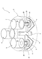
- the lens forming apparatus 1 according to the present embodiment will be described with reference to FIGS.
- the lens forming apparatus 1 described here is merely an example, and various design changes can be made.
- a lens forming apparatus 1 includes a transfer chamber 2 having a substantially columnar shape, and first and second rotary tables 4 that rotate independently around a rotation shaft 3 inside the transfer chamber 2. 5 and a rotary drive mechanism 6 for driving the first and second rotary tables 4 and 5 to rotate.
- first and second molding chambers 7 and 8 which are spaced apart in the circumferential direction around the rotation shaft 3, and a mold accommodating chamber (mold exchange chamber) 100 to be described later.
- a casing (bell jar) 9 constituting a part thereof is provided.
- the first and second molding chambers 7 and 8 and the casing 9 are arranged at substantially equal angular intervals (approximately 120 ° intervals) in the circumferential direction around the rotating shaft 3. Has a degree of freedom, and various design changes are possible.
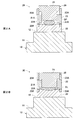
- a mold unit 30 having a pedestal 10 and a mold 20 is placed on the upper surfaces of the first and second turntables 4 and 5.
- the pedestal 10 has a large-diameter step 11 located below and a small-diameter step 12 located above.
- the mold 20 has an upper mold 21, a lower mold 22, and a body mold 23.
- the upper mold 21 has a molding surface 21A that matches the desired lens shape
- the lower mold 22 has a molding surface 22A that matches the desired lens shape.
- the body die 23 defines the mutual position of the upper die 21 and the lower die 22 in the radial direction, and has a gas vent hole 23A for releasing gas inside the die 20 during press molding.
- the glass preform (preform) GP is held between the molding surface 21A of the upper mold 21 and the molding surface 22A of the lower mold 22 in a state of being sandwiched therebetween.
- the upper mold 21 and the lower mold 22 are pressed so as to be close to each other in the vertical direction, and the molding surface 21 ⁇ / b> A is formed between the upper mold 21 and the lower mold 22.
- the glass lens (lens) GL to which the shape of the molding surface 22A is transferred is molded.
- the mold 20 has a function of pressing the glass preform (preform) GP to form the glass lens (lens) GL.
- the mold unit 30 placed on the first and second turntables 4 and 5 is moved to the first and second molding chambers 7 and 8. And the lower part of the casing 9.
- the mold unit 30 is moved into the transfer chamber 2 between the first molding chamber 7 and the first and second turntables 4 and 5 located therebelow.
- the mold unit 30 is moved between the second molding chamber 8 and the first and second turntables 4 and 5 located thereunder, and the first and second casings 9 and the first and second turntables 4 located therebelow.
- a moving mechanism for moving the mold unit 30 between the rotary tables 4 and 5 is provided.
- the first and second turntables 4 and 5 are formed with through holes smaller than the mounting area of the mold unit 30, and push up the mold unit 30 through the through holes.
- a rod R (FIGS. 3 to 5) is provided. When the push-up rod R moves up and down, the mold unit 30 also moves up and down.
- An opening 2B that allows the mold unit 30 to move by connecting the transfer chamber 2 and the first molding chamber 7 to the ceiling wall 2A of the transfer chamber 2, a transfer chamber 2 and a second molding chamber.
- An opening 2C that allows the mold unit 30 to move by communicating the mold unit 8 and an opening 2D that allows the mold unit 30 to move by communicating the transfer chamber 2 with the casing 9 are formed.
- the first and second rotary tables 4 and 5 and the above-described moving mechanism are used to move the mold 20 before press molding (FIG. 2A) and the mold 20 after press molding (FIG. 2B) into first and second moldings.
- Each process can be performed by moving between the chambers 7 and 8 and the casing 9.
- the first and second rotary tables 4 and 5 can be independently rotated, for example, while the first rotary table 4 is stopped in the first molding chamber 7 and press molding of the mold unit 30 is performed.
- flexible control of rotating the second rotary table 5 to move the mold unit 30 between the second molding chamber 8 and the casing 9 becomes possible.
- the first and second molding chambers 7 and 8 have a substantially cylindrical space defined by a casing.
- the glass preform GP contained in the mold 20 before press molding is filled with the glass preform GP contained in the first and second molding chambers 7 and 8 by about 10 ° C. to 30 ° C. below the glass yield point.
- a heating mechanism for example, a heater
- a press mechanism for pressing the upper mold 21 and the lower mold 22 so as to approach in the vertical direction to press the glass preform GP to form the glass lens GL.
- the casing 9 has a substantially cylindrical space. That is, casing 9 has ceiling wall 9A and side wall 9B extending downward from the outer peripheral edge of ceiling wall 9A.
- the casing 9 is supported so as to be able to move up and down by a drive mechanism (not shown).
- the lower end of the side wall 9B is applied to the upper surface around the opening 2D of the ceiling wall 2A of the transfer chamber 2 via the O-ring 9C.
- the transfer chamber 2 and the casing 9 are hermetically sealed and isolated from outside air.
- the first and second rotary tables 4 and 5 and the moving mechanism described above raise the press-formed mold 20 (FIG. 2B) together with the pedestal 10, the upper surface of the large-diameter step portion 11 of the pedestal 10 becomes an O-ring. It is applied to the lower surface around the opening 2D of the ceiling wall 2A of the transfer chamber 2 via the transfer chamber 11A. Thereby, the transfer chamber 2 and the casing 9 are partitioned and shut off, and a fluid such as a gas flows between the transfer chamber 2 and the casing 9 except for a case where a “vacuum gas replacement process” described later is performed. Is prevented.
- a space surrounded by the ceiling wall 2A of the transfer chamber 2, the casing 9, and the pedestal 10 is formed.
- this space is referred to as a mold accommodating chamber (mold exchanging chamber) 100.
- the mold accommodating chamber (mold exchanging chamber) 100 has a cooling mechanism for cooling the mold 20 (FIG. 2B) after press molding.
- the press-molded mold 20 rises together with the pedestal 10 and is accommodated in the casing 9, the press-molded mold 20 is cooled by the cooling mechanism. Thereafter, when the casing 9 is raised, the cooled mold 20 is exposed, the cooled mold 20 is taken out, and the unmolded mold 20 (FIG. 2A) is placed on the upper surface of the small-diameter step portion 12 of the pedestal 10. Can be arranged. Thereafter, when the housing space of the mold housing chamber 100 is formed by lowering the casing 9, the mold 20 before press molding is arranged in the housing space of the mold housing chamber 100.
- the mold accommodating chamber 100 has a function of accommodating the mold 20 before the press instead of the mold 20 after the press (the mold 20 after the press is carried out and the mold 20 before the press is carried in). Function).
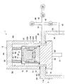
- FIG. 3 shows a state in which the mold 20 (FIG. 2A) before press molding is housed in the mold housing chamber 100.
- “vacuum gas replacement” is performed in which a gas (for example, nitrogen gas) is sent after evacuation of the mold housing chamber 100. This is to expel outside air (oxygen) that has entered the mold accommodating chamber 100 when the mold unit 20 is replaced, thereby preventing the mold unit 20 from being deteriorated (oxidized) during press molding. That is, when outside air (oxygen) enters the mold accommodating chamber 100, when the outside air (oxygen) flows into the transfer chamber 2 and the first and second molding chambers 7 and 8, the outside air (oxygen) flows in and press-molds. This is to prevent this from happening because it may have a bad effect. It is to be noted that a mode in which gas is sent into the mold accommodating chamber 100 without performing “vacuum gas replacement” is also possible.
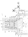
- the transfer chamber 2 is formed with a first gas passage 2E formed across the ceiling wall 2A in the left-right direction (horizontal direction).
- the left end of the first gas passage 2E is open toward the vicinity of the side surface of the small-diameter step portion 12 of the pedestal 10, and the right end of the first gas passage 2E is connected to the outside of the transfer chamber 2 by a first end. It communicates with the gas pipe 41.
- the first gas passage 2 ⁇ / b> E communicates the first gas pipe 41 with the mold accommodating chamber 100 which is partitioned (blocked) from the transfer chamber 2.
- a second gas passage 2G formed in a side wall 2F lower than the ceiling wall 2A is formed.
- the second gas passage 2 ⁇ / b> G communicates the second gas pipe 42 with the transfer chamber 2 partitioned (closed) from the mold accommodating chamber 100.
- the second gas pipe 42 is provided with an electromagnetic valve V2.
- the first gas pipe 41 and the second gas pipe 42 join at a pipe junction 40.
- a third gas pipe 43 connected to the vacuum pump VP via the solenoid valve V1 and a fourth gas pipe 44 provided with the solenoid valve V3 join the pipe junction 40.
- the solenoid valves V1 to V3 are controlled to open and close by a solenoid valve control unit (not shown) so that when one of the solenoid valves is open, the other two solenoid valves are closed.
- the gas inside the transfer chamber 2 flows from the second gas passage 2G to the second gas passage 2G and the second gas passage 2G. Is supplied to the mold accommodating chamber 100 via the gas pipe 42, the pipe junction 40, the first gas pipe 41, and the first gas passage 2E.
- the solenoid valve V3 is opened and the solenoid valves V1 and V2 are closed to bring the internal pressure of the mold accommodating chamber 100 close to the atmospheric pressure. Can be.
- the first gas passage 2E, the second gas passage 2G, the pipe junction 40, the first gas pipe 41, the second gas pipe 42, the third gas pipe 43, and the fourth gas pipe 44, the solenoid valves V1-V3 and the vacuum pump VP function as "gas supply means" for supplying gas after depressurizing (evacuating) the mold housing chamber 100.
- the transfer chamber 2 is in an inert gas atmosphere.
- the inert gas for example, nitrogen or argon is used, and the oxygen concentration is preferably 5 ppm or less.
- the gas supplied to the mold accommodating chamber 100 is an inert gas existing in the transfer chamber 2.
- this is an environment state in which foreign matters (dust, contaminants) are less than in the outside air.
- the components of the mold 20 for example, the upper mold 21, the lower mold 22, and the body mold 23. If it enters into the gap or the gas vent hole 23A, there is a possibility that a high-quality glass lens GL cannot be formed.
- the filter device 50 that covers at least a part of the mold 20 before press molding housed (conveyed) into the mold housing chamber 100, the components of the mold 20 (for example, the upper mold) are provided. Foreign matter is prevented from entering the gap between the mold 21, the lower mold 22 and the body mold 23) and the gas vent hole 23A, and a high-quality glass lens GL has been successfully formed.
- the filter device 50 a specific configuration of the filter device 50 will be described in detail.
- the filter device 50 includes a filter support portion 60 extending downward from the ceiling wall 9A of the casing 9 (the mold accommodating chamber 100) toward the mold 20 before press molding, and a filter portion 70 supported by the filter support portion 60. And a bell-type filter device.
- the filter portion 70 includes an upper surface portion 71 located above the mold 20 before press molding, a side surface portion 72 extending downward from the outer peripheral edge of the upper surface portion 71 and located on the side of the mold 20 before press molding. Having. At the lower end of the side surface portion 72, a cushion portion 73 made of, for example, a silicon material is provided.
- the filter unit 70 (the upper surface unit 71 and the side surface unit 72) has a mesh portion made of, for example, a sintered metal and / or a porous metal (for example, a SUS material or the like).
- the fineness of the mesh portion can be, for example, about 10 ⁇ m in order to prevent foreign substances of 30 ⁇ m or more from being mixed.
- the filter supporting portion 60 includes a coil spring (elastic portion) 61 extending vertically between the ceiling wall 9A of the casing 9 (the mold accommodating chamber 100) and the upper surface 71 of the filter portion 70, and the casing 9 (the mold). And a guide rod (guide portion) 62 extending downward from the ceiling wall 9A of the storage chamber 100) toward the upper surface portion 71 of the filter portion 70. The lower end of the guide rod 62 and the upper surface 71 of the filter 70 are not in contact with each other. A guide rod 62 is inserted into the coil spring 61, and the coil spring 61 is vertically expandable and contractable under the guide of the guide rod 62 in the vertical direction.
- a coil spring (elastic portion) 61 extending vertically between the ceiling wall 9A of the casing 9 (the mold accommodating chamber 100) and the upper surface 71 of the filter portion 70, and the casing 9 (the mold).
- a guide rod (guide portion) 62 extending downward from the ceiling wall 9A of the storage chamber 100)
- the coil spring 61 and the guide rod 62 of the filter support portion 60 are provided, for example, at least three sets spaced apart in the circumferential direction (for example, three sets at 120 ° intervals, four sets at 90 ° intervals, and 60 ° intervals). 6 sets). 3 to 5, at least two of the three sets of the coil spring 61 and the guide rod 62 are illustrated.
- the pedestal 10 mounts the mold 20 and moves (elevates) between an ascending position forming the mold accommodating chamber 100 and a descending position not constituting the mold accommodating chamber 100.
- the coil spring 61 of the filter supporting unit 60 is in a free state or a slightly expanded state due to the weight of the filter unit 70 ( Not compressed vertically).
- the cushion portion 73 provided at the lower end of the side surface portion 72 of the filter unit 70 is , And comes into contact with the upper surface of the small-diameter step portion 12 of the pedestal 10 and is compressed.
- the coil spring 61 of the filter support portion 60 is vertically compressed by receiving the guide rod 62 in the up and down direction, so that the cushion portion 73 of the filter portion 70 is pressed against the pedestal 10.
- the filter portion 70 (the upper surface portion 71 and the side surface portion 72). Therefore, as shown in FIG. 5, in the “vacuum gas replacement”, an inert gas is supplied from the transfer chamber 2 to the mold accommodating chamber 100, and the inert gas contains foreign matter of several ⁇ m to several tens ⁇ m. Even if there is, it is possible to reliably prevent the foreign matter from entering the gap between the components of the mold 20 (for example, the upper mold 21, the lower mold 22, and the body mold 23) and the gas vent hole 23A. As a result, a high quality glass lens GL can be formed.
- the filter device 50 If the filter device 50 is continuously used, foreign substances may be deposited on the mesh portion of the filter portion 70 (the upper surface portion 71 and the side surface portion 72). In this case, the filter unit 70 can be cleaned or replaced. Further, the mesh portion of the filter portion 70 (the upper surface portion 71 and the side surface portion 72) may have a function of not only blocking foreign substances but also actively adsorbing foreign substances.
- the lens forming apparatus 1 of the present embodiment presses the glass preform (preform) GP to form the glass lens (lens) GL, and the mold for housing the die 20 before pressing. It has a mold accommodating chamber 100 and a filter device 50 that covers at least a part of the mold 20 before the press accommodated in the mold accommodating chamber 100. This prevents (blocks) foreign matter from entering the gaps between the components of the mold 20 (for example, the upper mold 21, the lower mold 22, and the body mold 23) and the gas vent hole 23 ⁇ / b> A, and provides a high-quality glass lens (lens). )
- the GL can be formed.
- the mold accommodating chamber 100 functions as a “mold exchanging chamber” for accommodating the mold 20 before the press instead of the mold 20 after the press.
- the exchange of the mold 20 before and after the press is performed in a room different from the mold accommodating chamber 100, and the mold accommodating chamber 100 is moved in the process of transferring the mold 20 before the press in the apparatus.
Landscapes
- Engineering & Computer Science (AREA)
- Chemical & Material Sciences (AREA)
- Manufacturing & Machinery (AREA)
- Materials Engineering (AREA)
- Organic Chemistry (AREA)
- Re-Forming, After-Treatment, Cutting And Transporting Of Glass Products (AREA)
- Moulds For Moulding Plastics Or The Like (AREA)
Priority Applications (1)
| Application Number | Priority Date | Filing Date | Title |
|---|---|---|---|
| CN201980043671.7A CN112351956B (zh) | 2018-07-04 | 2019-07-03 | 透镜成型装置以及过滤器装置 |
Applications Claiming Priority (2)
| Application Number | Priority Date | Filing Date | Title |
|---|---|---|---|
| JP2018127306A JP7089422B2 (ja) | 2018-07-04 | 2018-07-04 | レンズ成形装置及びフィルタ装置 |
| JP2018-127306 | 2018-07-04 |
Publications (1)
| Publication Number | Publication Date |
|---|---|
| WO2020009153A1 true WO2020009153A1 (ja) | 2020-01-09 |
Family
ID=69059204
Family Applications (1)
| Application Number | Title | Priority Date | Filing Date |
|---|---|---|---|
| PCT/JP2019/026475 Ceased WO2020009153A1 (ja) | 2018-07-04 | 2019-07-03 | レンズ成形装置及びフィルタ装置 |
Country Status (3)
| Country | Link |
|---|---|
| JP (1) | JP7089422B2 (enExample) |
| CN (1) | CN112351956B (enExample) |
| WO (1) | WO2020009153A1 (enExample) |
Families Citing this family (1)
| Publication number | Priority date | Publication date | Assignee | Title |
|---|---|---|---|---|
| KR102874307B1 (ko) * | 2024-03-07 | 2025-10-21 | 국립창원대학교 산학협력단 | 비구면렌즈의 제조장치 및 그 제조방법 |
Citations (5)
| Publication number | Priority date | Publication date | Assignee | Title |
|---|---|---|---|---|
| JPH08277128A (ja) * | 1995-04-05 | 1996-10-22 | Olympus Optical Co Ltd | 光学素子の成形装置 |
| JP2005330152A (ja) * | 2004-05-20 | 2005-12-02 | Konica Minolta Opto Inc | 光学素子の成形方法及び光学素子 |
| JP2009143767A (ja) * | 2007-12-14 | 2009-07-02 | Fujifilm Corp | 成形方法及び装置 |
| JP2011121825A (ja) * | 2009-12-11 | 2011-06-23 | Olympus Corp | 光学素子成形方法および成形装置 |
| JP2012158508A (ja) * | 2011-02-02 | 2012-08-23 | Olympus Corp | 気体置換用チャンバー装置、及び、光学素子の製造方法 |
Family Cites Families (4)
| Publication number | Priority date | Publication date | Assignee | Title |
|---|---|---|---|---|
| TWI265305B (en) * | 2005-09-13 | 2006-11-01 | Asia Optical Co Inc | Integration of optical product with multiple optical components and casting apparatus thereof |
| JP2007302526A (ja) * | 2006-05-12 | 2007-11-22 | Ohara Inc | ガラス成形装置、ガラス成形方法、及びガラス成形品製造装置 |
| CN201424426Y (zh) * | 2009-05-05 | 2010-03-17 | 福耀集团(上海)汽车玻璃有限公司 | 一种玻璃模具 |
| JP5904493B2 (ja) * | 2012-09-10 | 2016-04-13 | Hoya株式会社 | ガラス成形装置及びガラス成形方法 |
-
2018
- 2018-07-04 JP JP2018127306A patent/JP7089422B2/ja not_active Expired - Fee Related
-
2019
- 2019-07-03 CN CN201980043671.7A patent/CN112351956B/zh not_active Expired - Fee Related
- 2019-07-03 WO PCT/JP2019/026475 patent/WO2020009153A1/ja not_active Ceased
Patent Citations (5)
| Publication number | Priority date | Publication date | Assignee | Title |
|---|---|---|---|---|
| JPH08277128A (ja) * | 1995-04-05 | 1996-10-22 | Olympus Optical Co Ltd | 光学素子の成形装置 |
| JP2005330152A (ja) * | 2004-05-20 | 2005-12-02 | Konica Minolta Opto Inc | 光学素子の成形方法及び光学素子 |
| JP2009143767A (ja) * | 2007-12-14 | 2009-07-02 | Fujifilm Corp | 成形方法及び装置 |
| JP2011121825A (ja) * | 2009-12-11 | 2011-06-23 | Olympus Corp | 光学素子成形方法および成形装置 |
| JP2012158508A (ja) * | 2011-02-02 | 2012-08-23 | Olympus Corp | 気体置換用チャンバー装置、及び、光学素子の製造方法 |
Also Published As
| Publication number | Publication date |
|---|---|
| JP7089422B2 (ja) | 2022-06-22 |
| JP2020007172A (ja) | 2020-01-16 |
| CN112351956B (zh) | 2022-08-02 |
| CN112351956A (zh) | 2021-02-09 |
Similar Documents
| Publication | Publication Date | Title |
|---|---|---|
| JP6398761B2 (ja) | 基板処理装置 | |
| CN109300806B (zh) | 真空处理设备 | |
| KR101213390B1 (ko) | 서브챔버를 가지는 에칭 챔버 | |
| JP2003017543A (ja) | 基板処理装置、基板処理方法、半導体装置の製造方法および搬送装置 | |
| TWI471660B (zh) | 密封裝置 | |
| JP2021072450A (ja) | 支持ユニット、これを含む基板処理装置、及びこれを利用する基板処理方法 | |
| CN106971960A (zh) | 用于处理基板的装置和方法 | |
| US20210233790A1 (en) | Batch substrate support with warped substrate capability | |
| CN115440641A (zh) | 十二边形传送腔室和具有十二边形传送腔室的处理系统 | |
| JP5958446B2 (ja) | ロードポート装置 | |
| JP5898523B2 (ja) | 真空処理装置および真空処理装置を用いた物品の製造方法 | |
| KR20220044122A (ko) | 성막 장치 | |
| WO2020009153A1 (ja) | レンズ成形装置及びフィルタ装置 | |
| KR20010006810A (ko) | 고온 고압 처리 장치 | |
| CN114197056B (zh) | 一种半导体材料退火装置及退火方法 | |
| JP2012168386A (ja) | 封止方法およびその装置 | |
| JP2009070868A (ja) | 基板収納用容器 | |
| KR100681091B1 (ko) | 몰드프레스 성형장치 및 성형체의 제조방법 | |
| JP2004087781A (ja) | 真空処理装置及び真空処理方法 | |
| US20230033715A1 (en) | Substrate processing apparatus | |
| JP2010027810A (ja) | 真空搬送装置 | |
| JP2018157025A (ja) | 基板処理装置 | |
| JP2006199537A (ja) | ガラス成形装置 | |
| JP4015818B2 (ja) | 半導体製造装置 | |
| JP2010027809A (ja) | ワーク搬送用容器の開閉機構を備えた搬送装置 |
Legal Events
| Date | Code | Title | Description |
|---|---|---|---|
| 121 | Ep: the epo has been informed by wipo that ep was designated in this application |
Ref document number: 19830124 Country of ref document: EP Kind code of ref document: A1 |
|
| NENP | Non-entry into the national phase |
Ref country code: DE |
|
| 122 | Ep: pct application non-entry in european phase |
Ref document number: 19830124 Country of ref document: EP Kind code of ref document: A1 |