WO2020009153A1 - レンズ成形装置及びフィルタ装置 - Google Patents
レンズ成形装置及びフィルタ装置 Download PDFInfo
- Publication number
- WO2020009153A1 WO2020009153A1 PCT/JP2019/026475 JP2019026475W WO2020009153A1 WO 2020009153 A1 WO2020009153 A1 WO 2020009153A1 JP 2019026475 W JP2019026475 W JP 2019026475W WO 2020009153 A1 WO2020009153 A1 WO 2020009153A1
- Authority
- WO
- WIPO (PCT)
- Prior art keywords
- mold
- press
- lens
- filter
- accommodating chamber
- Prior art date
- Legal status (The legal status is an assumption and is not a legal conclusion. Google has not performed a legal analysis and makes no representation as to the accuracy of the status listed.)
- Ceased
Links
Images

Classifications
-
- C—CHEMISTRY; METALLURGY
- C03—GLASS; MINERAL OR SLAG WOOL
- C03B—MANUFACTURE, SHAPING, OR SUPPLEMENTARY PROCESSES
- C03B11/00—Pressing molten glass or performed glass reheated to equivalent low viscosity without blowing
-
- C—CHEMISTRY; METALLURGY
- C03—GLASS; MINERAL OR SLAG WOOL
- C03B—MANUFACTURE, SHAPING, OR SUPPLEMENTARY PROCESSES
- C03B11/00—Pressing molten glass or performed glass reheated to equivalent low viscosity without blowing
- C03B11/02—Pressing molten glass or performed glass reheated to equivalent low viscosity without blowing in machines with rotary tables
-
- C—CHEMISTRY; METALLURGY
- C03—GLASS; MINERAL OR SLAG WOOL
- C03B—MANUFACTURE, SHAPING, OR SUPPLEMENTARY PROCESSES
- C03B11/00—Pressing molten glass or performed glass reheated to equivalent low viscosity without blowing
- C03B11/16—Gearing or controlling mechanisms specially adapted for glass presses
Definitions
- the present invention relates to a lens forming device and a filter device.
- Patent Document 1 discloses an apparatus for manufacturing a glass molded body that manufactures a glass molded body by heating and press-molding a glass material disposed in a mold unit.
- the apparatus for manufacturing a glass molded body includes first and second rotary tables on which a mold unit is placed and which rotates independently about a rotary axis, and a rotary axis of the first and second rotary tables.
- First and second forming sections and an exchange cooling section which are located apart from each other in the circumferential direction, and a mold between the first and second turntables and the first and second forming sections and the exchange cooling section.
- a moving mechanism for moving the unit is provided.
- the mold unit containing the glass material is supplied to the first and second molding units to perform press molding, and the mold unit after the press molding is replaced with an exchange cooling unit. Then, the cooled mold unit is carried out of the apparatus, and another mold unit containing a glass material is carried into the apparatus (cooling and replacement of the mold unit).
- the exchange cooling unit has an accommodation space defined by a casing.
- the casing is provided with an opening that can be opened and closed by a shutter. Through this opening, the cooled mold unit is carried out of the housing space of the casing, and another mold unit containing a glass material is placed. It can be carried into the housing space of the casing (the mold unit can be replaced).
- the housing space of the casing may be evacuated, and then a vacuum gas replacement for feeding a gas (for example, nitrogen gas) may be performed.
- a gas for example, nitrogen gas
- gas may be sent into the housing space of the casing without performing evacuation.
- the present invention has been made based on the above awareness of problems, and an object of the present invention is to provide a lens forming apparatus and a filter apparatus capable of forming a high-quality lens by reducing the adverse effects of foreign matters.
- the lens forming apparatus includes a mold for pressing a preform to form a lens, a mold accommodating chamber for accommodating a mold before pressing, and a mold accommodating in the mold accommodating chamber. And a filter device that covers at least a part of the mold.
- the lens molding apparatus of the present embodiment can further include a gas supply unit that supplies gas after depressurizing the mold accommodating chamber.
- the filter device includes a filter supporting portion extending downward from a ceiling wall of the mold accommodating chamber toward the mold before pressing, and a filter supporting portion supported by the filter supporting portion and positioned above the mold before pressing.
- a filter portion having an upper surface portion and a side portion extending downward from an outer peripheral edge of the upper surface portion and located on a side of the mold before pressing can be provided.
- the lens forming apparatus of the present embodiment further includes a pedestal on which the mold is placed and which moves between an ascending position configuring the mold accommodating chamber and a descending position not configuring the mold accommodating chamber, In the ascending position of the pedestal, the lower end of the side surface of the filter unit can contact the pedestal on the side of the mold.
- a cushion portion that is compressed when the filter portion abuts on the pedestal can be provided at the lower end portion of the side surface portion of the filter portion.
- the filter supporting portion has an elastic portion that is not compressed in the vertical direction at the lowered position of the pedestal and is compressed in the vertical direction at the raised position of the pedestal, and a guide portion that guides the elastic portion in the vertical direction. be able to.
- the elastic part may be formed of a coil spring, and the guide may be formed of a guide rod inserted through the coil spring.
- At least three sets of the coil spring and the guide rod can be provided apart from each other in the circumferential direction.
- the filter section may have a mesh section made of a sintered metal and / or a porous metal.
- the mold accommodating chamber accommodates the mold before the press in place of the mold after the press, or accommodates the mold before the press in the process of transporting the mold before the press in the apparatus. be able to.
- the filter device of the present embodiment is a filter device used for a lens forming device having a mold for pressing a preform to form a lens and a mold accommodating chamber for accommodating a mold before pressing. And covering at least a part of the mold before the press accommodated in the mold accommodating chamber.
- the present invention it is possible to obtain a lens forming device and a filter device capable of forming a high-quality lens while reducing the adverse effects of foreign matter.
- the lens forming apparatus 1 according to the present embodiment will be described with reference to FIGS.
- the lens forming apparatus 1 described here is merely an example, and various design changes can be made.
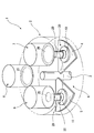
- a lens forming apparatus 1 includes a transfer chamber 2 having a substantially columnar shape, and first and second rotary tables 4 that rotate independently around a rotation shaft 3 inside the transfer chamber 2. 5 and a rotary drive mechanism 6 for driving the first and second rotary tables 4 and 5 to rotate.
- first and second molding chambers 7 and 8 which are spaced apart in the circumferential direction around the rotation shaft 3, and a mold accommodating chamber (mold exchange chamber) 100 to be described later.
- a casing (bell jar) 9 constituting a part thereof is provided.
- the first and second molding chambers 7 and 8 and the casing 9 are arranged at substantially equal angular intervals (approximately 120 ° intervals) in the circumferential direction around the rotating shaft 3. Has a degree of freedom, and various design changes are possible.
- a mold unit 30 having a pedestal 10 and a mold 20 is placed on the upper surfaces of the first and second turntables 4 and 5.
- the pedestal 10 has a large-diameter step 11 located below and a small-diameter step 12 located above.
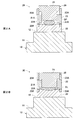
- the mold 20 has an upper mold 21, a lower mold 22, and a body mold 23.
- the upper mold 21 has a molding surface 21A that matches the desired lens shape
- the lower mold 22 has a molding surface 22A that matches the desired lens shape.
- the body die 23 defines the mutual position of the upper die 21 and the lower die 22 in the radial direction, and has a gas vent hole 23A for releasing gas inside the die 20 during press molding.
- the glass preform (preform) GP is held between the molding surface 21A of the upper mold 21 and the molding surface 22A of the lower mold 22 in a state of being sandwiched therebetween.
- the upper mold 21 and the lower mold 22 are pressed so as to be close to each other in the vertical direction, and the molding surface 21 ⁇ / b> A is formed between the upper mold 21 and the lower mold 22.
- the glass lens (lens) GL to which the shape of the molding surface 22A is transferred is molded.
- the mold 20 has a function of pressing the glass preform (preform) GP to form the glass lens (lens) GL.
- the mold unit 30 placed on the first and second turntables 4 and 5 is moved to the first and second molding chambers 7 and 8. And the lower part of the casing 9.
- the mold unit 30 is moved into the transfer chamber 2 between the first molding chamber 7 and the first and second turntables 4 and 5 located therebelow.
- the mold unit 30 is moved between the second molding chamber 8 and the first and second turntables 4 and 5 located thereunder, and the first and second casings 9 and the first and second turntables 4 located therebelow.
- a moving mechanism for moving the mold unit 30 between the rotary tables 4 and 5 is provided.
- the first and second turntables 4 and 5 are formed with through holes smaller than the mounting area of the mold unit 30, and push up the mold unit 30 through the through holes.
- a rod R (FIGS. 3 to 5) is provided. When the push-up rod R moves up and down, the mold unit 30 also moves up and down.
- An opening 2B that allows the mold unit 30 to move by connecting the transfer chamber 2 and the first molding chamber 7 to the ceiling wall 2A of the transfer chamber 2, a transfer chamber 2 and a second molding chamber.
- An opening 2C that allows the mold unit 30 to move by communicating the mold unit 8 and an opening 2D that allows the mold unit 30 to move by communicating the transfer chamber 2 with the casing 9 are formed.
- the first and second rotary tables 4 and 5 and the above-described moving mechanism are used to move the mold 20 before press molding (FIG. 2A) and the mold 20 after press molding (FIG. 2B) into first and second moldings.
- Each process can be performed by moving between the chambers 7 and 8 and the casing 9.
- the first and second rotary tables 4 and 5 can be independently rotated, for example, while the first rotary table 4 is stopped in the first molding chamber 7 and press molding of the mold unit 30 is performed.
- flexible control of rotating the second rotary table 5 to move the mold unit 30 between the second molding chamber 8 and the casing 9 becomes possible.
- the first and second molding chambers 7 and 8 have a substantially cylindrical space defined by a casing.
- the glass preform GP contained in the mold 20 before press molding is filled with the glass preform GP contained in the first and second molding chambers 7 and 8 by about 10 ° C. to 30 ° C. below the glass yield point.
- a heating mechanism for example, a heater
- a press mechanism for pressing the upper mold 21 and the lower mold 22 so as to approach in the vertical direction to press the glass preform GP to form the glass lens GL.
- the casing 9 has a substantially cylindrical space. That is, casing 9 has ceiling wall 9A and side wall 9B extending downward from the outer peripheral edge of ceiling wall 9A.
- the casing 9 is supported so as to be able to move up and down by a drive mechanism (not shown).
- the lower end of the side wall 9B is applied to the upper surface around the opening 2D of the ceiling wall 2A of the transfer chamber 2 via the O-ring 9C.
- the transfer chamber 2 and the casing 9 are hermetically sealed and isolated from outside air.
- the first and second rotary tables 4 and 5 and the moving mechanism described above raise the press-formed mold 20 (FIG. 2B) together with the pedestal 10, the upper surface of the large-diameter step portion 11 of the pedestal 10 becomes an O-ring. It is applied to the lower surface around the opening 2D of the ceiling wall 2A of the transfer chamber 2 via the transfer chamber 11A. Thereby, the transfer chamber 2 and the casing 9 are partitioned and shut off, and a fluid such as a gas flows between the transfer chamber 2 and the casing 9 except for a case where a “vacuum gas replacement process” described later is performed. Is prevented.
- a space surrounded by the ceiling wall 2A of the transfer chamber 2, the casing 9, and the pedestal 10 is formed.
- this space is referred to as a mold accommodating chamber (mold exchanging chamber) 100.
- the mold accommodating chamber (mold exchanging chamber) 100 has a cooling mechanism for cooling the mold 20 (FIG. 2B) after press molding.
- the press-molded mold 20 rises together with the pedestal 10 and is accommodated in the casing 9, the press-molded mold 20 is cooled by the cooling mechanism. Thereafter, when the casing 9 is raised, the cooled mold 20 is exposed, the cooled mold 20 is taken out, and the unmolded mold 20 (FIG. 2A) is placed on the upper surface of the small-diameter step portion 12 of the pedestal 10. Can be arranged. Thereafter, when the housing space of the mold housing chamber 100 is formed by lowering the casing 9, the mold 20 before press molding is arranged in the housing space of the mold housing chamber 100.
- the mold accommodating chamber 100 has a function of accommodating the mold 20 before the press instead of the mold 20 after the press (the mold 20 after the press is carried out and the mold 20 before the press is carried in). Function).
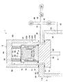
- FIG. 3 shows a state in which the mold 20 (FIG. 2A) before press molding is housed in the mold housing chamber 100.
- “vacuum gas replacement” is performed in which a gas (for example, nitrogen gas) is sent after evacuation of the mold housing chamber 100. This is to expel outside air (oxygen) that has entered the mold accommodating chamber 100 when the mold unit 20 is replaced, thereby preventing the mold unit 20 from being deteriorated (oxidized) during press molding. That is, when outside air (oxygen) enters the mold accommodating chamber 100, when the outside air (oxygen) flows into the transfer chamber 2 and the first and second molding chambers 7 and 8, the outside air (oxygen) flows in and press-molds. This is to prevent this from happening because it may have a bad effect. It is to be noted that a mode in which gas is sent into the mold accommodating chamber 100 without performing “vacuum gas replacement” is also possible.
- the transfer chamber 2 is formed with a first gas passage 2E formed across the ceiling wall 2A in the left-right direction (horizontal direction).
- the left end of the first gas passage 2E is open toward the vicinity of the side surface of the small-diameter step portion 12 of the pedestal 10, and the right end of the first gas passage 2E is connected to the outside of the transfer chamber 2 by a first end. It communicates with the gas pipe 41.
- the first gas passage 2 ⁇ / b> E communicates the first gas pipe 41 with the mold accommodating chamber 100 which is partitioned (blocked) from the transfer chamber 2.
- a second gas passage 2G formed in a side wall 2F lower than the ceiling wall 2A is formed.
- the second gas passage 2 ⁇ / b> G communicates the second gas pipe 42 with the transfer chamber 2 partitioned (closed) from the mold accommodating chamber 100.
- the second gas pipe 42 is provided with an electromagnetic valve V2.
- the first gas pipe 41 and the second gas pipe 42 join at a pipe junction 40.
- a third gas pipe 43 connected to the vacuum pump VP via the solenoid valve V1 and a fourth gas pipe 44 provided with the solenoid valve V3 join the pipe junction 40.
- the solenoid valves V1 to V3 are controlled to open and close by a solenoid valve control unit (not shown) so that when one of the solenoid valves is open, the other two solenoid valves are closed.
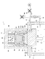
- the gas inside the transfer chamber 2 flows from the second gas passage 2G to the second gas passage 2G and the second gas passage 2G. Is supplied to the mold accommodating chamber 100 via the gas pipe 42, the pipe junction 40, the first gas pipe 41, and the first gas passage 2E.
- the solenoid valve V3 is opened and the solenoid valves V1 and V2 are closed to bring the internal pressure of the mold accommodating chamber 100 close to the atmospheric pressure. Can be.
- the first gas passage 2E, the second gas passage 2G, the pipe junction 40, the first gas pipe 41, the second gas pipe 42, the third gas pipe 43, and the fourth gas pipe 44, the solenoid valves V1-V3 and the vacuum pump VP function as "gas supply means" for supplying gas after depressurizing (evacuating) the mold housing chamber 100.
- the transfer chamber 2 is in an inert gas atmosphere.
- the inert gas for example, nitrogen or argon is used, and the oxygen concentration is preferably 5 ppm or less.
- the gas supplied to the mold accommodating chamber 100 is an inert gas existing in the transfer chamber 2.
- this is an environment state in which foreign matters (dust, contaminants) are less than in the outside air.
- the components of the mold 20 for example, the upper mold 21, the lower mold 22, and the body mold 23. If it enters into the gap or the gas vent hole 23A, there is a possibility that a high-quality glass lens GL cannot be formed.
- the filter device 50 that covers at least a part of the mold 20 before press molding housed (conveyed) into the mold housing chamber 100, the components of the mold 20 (for example, the upper mold) are provided. Foreign matter is prevented from entering the gap between the mold 21, the lower mold 22 and the body mold 23) and the gas vent hole 23A, and a high-quality glass lens GL has been successfully formed.
- the filter device 50 a specific configuration of the filter device 50 will be described in detail.
- the filter device 50 includes a filter support portion 60 extending downward from the ceiling wall 9A of the casing 9 (the mold accommodating chamber 100) toward the mold 20 before press molding, and a filter portion 70 supported by the filter support portion 60. And a bell-type filter device.
- the filter portion 70 includes an upper surface portion 71 located above the mold 20 before press molding, a side surface portion 72 extending downward from the outer peripheral edge of the upper surface portion 71 and located on the side of the mold 20 before press molding. Having. At the lower end of the side surface portion 72, a cushion portion 73 made of, for example, a silicon material is provided.
- the filter unit 70 (the upper surface unit 71 and the side surface unit 72) has a mesh portion made of, for example, a sintered metal and / or a porous metal (for example, a SUS material or the like).
- the fineness of the mesh portion can be, for example, about 10 ⁇ m in order to prevent foreign substances of 30 ⁇ m or more from being mixed.
- the filter supporting portion 60 includes a coil spring (elastic portion) 61 extending vertically between the ceiling wall 9A of the casing 9 (the mold accommodating chamber 100) and the upper surface 71 of the filter portion 70, and the casing 9 (the mold). And a guide rod (guide portion) 62 extending downward from the ceiling wall 9A of the storage chamber 100) toward the upper surface portion 71 of the filter portion 70. The lower end of the guide rod 62 and the upper surface 71 of the filter 70 are not in contact with each other. A guide rod 62 is inserted into the coil spring 61, and the coil spring 61 is vertically expandable and contractable under the guide of the guide rod 62 in the vertical direction.
- a coil spring (elastic portion) 61 extending vertically between the ceiling wall 9A of the casing 9 (the mold accommodating chamber 100) and the upper surface 71 of the filter portion 70, and the casing 9 (the mold).
- a guide rod (guide portion) 62 extending downward from the ceiling wall 9A of the storage chamber 100)
- the coil spring 61 and the guide rod 62 of the filter support portion 60 are provided, for example, at least three sets spaced apart in the circumferential direction (for example, three sets at 120 ° intervals, four sets at 90 ° intervals, and 60 ° intervals). 6 sets). 3 to 5, at least two of the three sets of the coil spring 61 and the guide rod 62 are illustrated.
- the pedestal 10 mounts the mold 20 and moves (elevates) between an ascending position forming the mold accommodating chamber 100 and a descending position not constituting the mold accommodating chamber 100.
- the coil spring 61 of the filter supporting unit 60 is in a free state or a slightly expanded state due to the weight of the filter unit 70 ( Not compressed vertically).
- the cushion portion 73 provided at the lower end of the side surface portion 72 of the filter unit 70 is , And comes into contact with the upper surface of the small-diameter step portion 12 of the pedestal 10 and is compressed.
- the coil spring 61 of the filter support portion 60 is vertically compressed by receiving the guide rod 62 in the up and down direction, so that the cushion portion 73 of the filter portion 70 is pressed against the pedestal 10.
- the filter portion 70 (the upper surface portion 71 and the side surface portion 72). Therefore, as shown in FIG. 5, in the “vacuum gas replacement”, an inert gas is supplied from the transfer chamber 2 to the mold accommodating chamber 100, and the inert gas contains foreign matter of several ⁇ m to several tens ⁇ m. Even if there is, it is possible to reliably prevent the foreign matter from entering the gap between the components of the mold 20 (for example, the upper mold 21, the lower mold 22, and the body mold 23) and the gas vent hole 23A. As a result, a high quality glass lens GL can be formed.
- the filter device 50 If the filter device 50 is continuously used, foreign substances may be deposited on the mesh portion of the filter portion 70 (the upper surface portion 71 and the side surface portion 72). In this case, the filter unit 70 can be cleaned or replaced. Further, the mesh portion of the filter portion 70 (the upper surface portion 71 and the side surface portion 72) may have a function of not only blocking foreign substances but also actively adsorbing foreign substances.
- the lens forming apparatus 1 of the present embodiment presses the glass preform (preform) GP to form the glass lens (lens) GL, and the mold for housing the die 20 before pressing. It has a mold accommodating chamber 100 and a filter device 50 that covers at least a part of the mold 20 before the press accommodated in the mold accommodating chamber 100. This prevents (blocks) foreign matter from entering the gaps between the components of the mold 20 (for example, the upper mold 21, the lower mold 22, and the body mold 23) and the gas vent hole 23 ⁇ / b> A, and provides a high-quality glass lens (lens). )
- the GL can be formed.
- the mold accommodating chamber 100 functions as a “mold exchanging chamber” for accommodating the mold 20 before the press instead of the mold 20 after the press.
- the exchange of the mold 20 before and after the press is performed in a room different from the mold accommodating chamber 100, and the mold accommodating chamber 100 is moved in the process of transferring the mold 20 before the press in the apparatus.
Landscapes
- Engineering & Computer Science (AREA)
- Chemical & Material Sciences (AREA)
- Manufacturing & Machinery (AREA)
- Materials Engineering (AREA)
- Organic Chemistry (AREA)
- Re-Forming, After-Treatment, Cutting And Transporting Of Glass Products (AREA)
- Moulds For Moulding Plastics Or The Like (AREA)
Abstract
異物による悪影響を低減して高品質なレンズを成形可能なレンズ成形装置及びフィルタ装置を得る。プリフォームをプレスしてレンズを成形する金型と、プレス前の金型を収容する金型収容室と、前記金型収容室に収容された前記プレス前の金型の少なくとも一部を覆うフィルタ装置と、を有することを特徴とするレンズ成形装置。プリフォームをプレスしてレンズを成形する金型と、プレス前の金型を収容する金型収容室と、を有するレンズ成形装置に使用されるフィルタ装置であって、前記金型収容室に収容された前記プレス前の金型の少なくとも一部を覆う、ことを特徴とするフィルタ装置。
Description
本発明は、レンズ成形装置及びフィルタ装置に関する。
特許文献1には、金型ユニット内に配置されたガラス材料を加熱してプレス成形することによりガラス成形体を製造するガラス成形体の製造装置が開示されている。ガラス成形体の製造装置は、金型ユニットが載置されるとともに回転軸を中心に独立して回転する第1、第2の回転テーブルと、第1、第2の回転テーブルの回転軸を中心とした周方向に離間して位置する第1、第2の成形部及び交換冷却部と、第1、第2の回転テーブルと第1、第2の成形部及び交換冷却部の間で金型ユニットを移動させる移動機構と、を有している。第1、第2の回転テーブル及び移動機構により、ガラス材料を収容した金型ユニットを第1、第2の成形部に供給してプレス成形を行い、プレス成形後の金型ユニットを交換冷却部に供給して冷却し、冷却後の金型ユニットを装置外に搬出するとともに、ガラス材料を収容した別の金型ユニットを装置内に搬入する(金型ユニットの冷却と交換を行う)。
交換冷却部は、ケーシングにより画成された収容空間を有している。ケーシングには、シャッタにより開閉可能な開口部が設けられており、この開口部を通して、冷却後の金型ユニットをケーシングの収容空間外に搬出するとともに、ガラス材料を収容した別の金型ユニットをケーシングの収容空間内に搬入することができる(金型ユニットを交換することができる)。
ところで、交換冷却部において金型ユニットを交換した後、ケーシングの収容空間を真空引きしてからガス(例えば窒素ガス)を送り込む真空ガス置換を行うことがある。これは、金型ユニットの交換時に入り込んだ外気(酸素)を追い出して、プレス成形時の金型ユニットの劣化(酸化)を防止するためである。あるいは、真空引きを行うことなくケーシングの収容空間にガスを送り込むことがある。
このとき、ケーシングの収容空間に送り込まれたガスに含まれる微小な異物(ゴミ、コンタミ)が金型ユニットの内部に入り込んで、その後のプレス成形に悪影響を及ぼすおそれがある。本発明者によると、たとえ数μm~数十μmの異物であっても、金型ユニットの構成要素(例えば上型と下型と胴型)の隙間やガス抜き穴に入り込んだ場合、高品質なレンズを成形できなくなってしまうおそれがある。
本発明は、以上の問題意識に基づいてなされたものであり、異物による悪影響を低減して高品質なレンズを成形可能なレンズ成形装置及びフィルタ装置を得ることを目的とする。
本実施形態のレンズ成形装置は、プリフォームをプレスしてレンズを成形する金型と、プレス前の金型を収容する金型収容室と、前記金型収容室に収容された前記プレス前の金型の少なくとも一部を覆うフィルタ装置と、を有することを特徴としている。
本実施形態のレンズ成形装置は、前記金型収容室を減圧してからガスを供給するガス供給手段をさらに有することができる。
前記フィルタ装置は、前記金型収容室の天井壁から前記プレス前の金型に向かって下方に延びるフィルタ支持部と、前記フィルタ支持部に支持されて前記プレス前の金型の上方に位置する上面部と、前記上面部の外周縁から下方に延びて前記プレス前の金型の側方に位置する側面部と、を有するフィルタ部と、を有することができる。
本実施形態のレンズ成形装置は、前記金型を載置するとともに、前記金型収容室を構成する上昇位置と前記金型収容室を構成しない下降位置の間で移動する台座をさらに有し、前記台座の上昇位置において、前記フィルタ部の前記側面部の下端部が前記金型の側方で前記台座に当接することができる。
前記フィルタ部の前記側面部の前記下端部に、前記台座に当接したときに圧縮されるクッション部を設けることができる。
前記フィルタ支持部は、前記台座の下降位置では上下方向に圧縮されず、前記台座の上昇位置では上下方向に圧縮される弾性部と、前記弾性部を上下方向に案内する案内部と、を有することができる。
前記弾性部は、コイルバネからなり、前記案内部は、前記コイルバネに挿通されたガイドロッドからなることができる。
前記コイルバネと前記ガイドロッドは、周方向に離間して少なくとも3組設けることができる。
前記フィルタ部は、焼結金属及び/又は多孔質金属から構成された網目部を有することができる。
前記金型収容室は、プレス後の金型に代えて前記プレス前の金型を収容する、又は、前記プレス前の金型を装置内で搬送する過程で前記プレス前の金型を収容することができる。
本実施形態のフィルタ装置は、プリフォームをプレスしてレンズを成形する金型と、プレス前の金型を収容する金型収容室と、を有するレンズ成形装置に使用されるフィルタ装置であって、前記金型収容室に収容された前記プレス前の金型の少なくとも一部を覆う、ことを特徴としている。
本発明によれば、異物による悪影響を低減して高品質なレンズを成形可能なレンズ成形装置及びフィルタ装置が得られる。
図1~図5を参照して、本実施形態によるレンズ成形装置1について説明する。なお、ここで説明するレンズ成形装置1はあくまで一例であり、種々の設計変更が可能である。
図1に示すように、レンズ成形装置1は、略円柱状をなす搬送室2と、搬送室2の内部で回転軸3を中心に独立して回転する第1、第2の回転テーブル4、5と、第1、第2の回転テーブル4、5を回転駆動する回転駆動機構6とを有している。搬送室2の上方には、回転軸3を中心とした周方向に離間して位置する第1、第2の成形室7、8と、後述する金型収容室(金型交換室)100の一部を構成するケーシング(ベルジャー)9とが設けられている。第1、第2の成形室7、8とケーシング9は、回転軸3を中心とした周方向に略等角度間隔(略120°間隔)で配置されているが、これらの配置数や配置角度には自由度があり、種々の設計変更が可能である。
第1、第2の回転テーブル4、5の上面には、台座10と金型20を有する金型ユニット30が載置される。
図2A、図2Bに示すように、台座10は、下方に位置する大径段部11と、上方に位置する小径段部12とを有している。金型20は、上型21と、下型22と、胴型23とを有している。上型21は所望のレンズ形状に合わせた成形面21Aを有しており、下型22は所望のレンズ形状に合わせた成形面22Aを有している。胴型23は、上型21と下型22の径方向の相互位置を規定するものであり、プレス成形時における金型20の内部のガスを逃がすためのガス抜き孔23Aを有している。
図2Aに示すように、プレス成形前の金型20では、上型21の成形面21Aと下型22の成形面22Aの間にガラスプリフォーム(プリフォーム)GPが挟み込まれた状態で保持される。図2Bに示すように、プレス成形後の金型20では、上型21と下型22が上下方向に近接するように加圧され、上型21と下型22の間に、成形面21Aと成形面22Aの形状が転写されたガラスレンズ(レンズ)GLが成形される。このように、金型20は、ガラスプリフォーム(プリフォーム)GPをプレスしてガラスレンズ(レンズ)GLを成形する機能を有している。
第1、第2の回転テーブル4、5が回転することにより、第1、第2の回転テーブル4、5に載置された金型ユニット30を、第1、第2の成形室7、8とケーシング9の下方に位置させることができる。図示は省略しているが、搬送室2には、第1の成形室7とその下方に位置する第1、第2の回転テーブル4、5との間で金型ユニット30を移動させ、第2の成形室8とその下方に位置する第1、第2の回転テーブル4、5との間で金型ユニット30を移動させ、且つ、ケーシング9とその下方に位置する第1、第2の回転テーブル4、5との間で金型ユニット30を移動させる移動機構が設けられている。より具体的に、第1、第2の回転テーブル4、5には、金型ユニット30の載置領域より小さい貫通孔が形成されており、この貫通孔を介して金型ユニット30を突き上げる突き上げロッドR(図3~図5)が設けられている。この突き上げロッドRが昇降することにより、金型ユニット30も昇降する。また、搬送室2の天井壁2Aには、搬送室2と第1の成形室7を連通させて金型ユニット30の移動を可能にする開口部2Bと、搬送室2と第2の成形室8を連通させて金型ユニット30の移動を可能にする開口部2Cと、搬送室2とケーシング9を連通させて金型ユニット30の移動を可能にする開口部2Dとが形成されている。
第1、第2の回転テーブル4、5と上述の移動機構により、プレス成形前の金型20(図2A)とプレス成形後の金型20(図2B)を、第1、第2の成形室7、8とケーシング9の間で移動させて各工程を行うことができる。特に、第1、第2の回転テーブル4、5が独立して回転できるので、例えば、第1の回転テーブル4を第1の成形室7で停止させて金型ユニット30のプレス成形を行う間に、第2の回転テーブル5を回転させて金型ユニット30を第2の成形室8とケーシング9の間で移動させるといった柔軟な制御が可能となる。
第1、第2の成形室7、8は、ケーシングにより画成された略円筒状の空間を有している。図示は省略しているが、第1、第2の成形室7、8の内部には、プレス成形前の金型20に含まれるガラスプリフォームGPをガラス屈伏点温度より10℃~30℃程度高い温度に加熱するための加熱機構(例えばヒータ)と、上型21と下型22を上下方向に近接するように加圧することでガラスプリフォームGPをプレスしてガラスレンズGLを成形するプレス機構とを有している。
図3に示すように、ケーシング9は、略円筒状の空間を有している。すなわち、ケーシング9は、天井壁9Aと、天井壁9Aの外周縁から下方に延びる側面壁9Bとを有している。ケーシング9は、図示を省略した駆動機構によって昇降自在に支持されている。ケーシング9の下降状態では、側面壁9Bの下端部が、Oリング9Cを介して、搬送室2の天井壁2Aの開口部2Dの周囲の上面に対して当て付けられている。これにより、搬送室2とケーシング9が密封されて外気と遮断されている。
第1、第2の回転テーブル4、5と上述の移動機構により、プレス成形後の金型20(図2B)が台座10とともに上昇すると、台座10の大径段部11の上面が、Oリング11Aを介して、搬送室2の天井壁2Aの開口部2Dの周囲の下面に対して当て付けられる。これにより、搬送室2とケーシング9が区画されて遮断され、後述する「真空ガス置換処理」を行う場合を除いて、搬送室2とケーシング9との間でガス等の流体が行き来することが防止される。
図3~図5に示すように、ケーシング9が下降状態かつ台座10が上昇状態のとき、搬送室2の天井壁2Aとケーシング9と台座10によって囲まれた空間が形成される。本実施形態では、この空間を金型収容室(金型交換室)100と呼ぶ。
図示を省略しているが、金型収容室(金型交換室)100は、プレス成形後の金型20(図2B)を冷却するための冷却機構を有している。プレス成形後の金型20が台座10とともに上昇してケーシング9の内部に収容されると、上記の冷却機構によりプレス成形後の金型20が冷却される。その後、ケーシング9が上昇すると、冷却後の金型20がむき出しになり、冷却後の金型20を取り出して、プレス成形前の金型20(図2A)を台座10の小径段部12の上面に配置することができる。その後、ケーシング9の下降により金型収容室100の収容空間が形成されると、その金型収容室100の収容空間内にプレス成形前の金型20が配置される。このように、金型収容室100は、プレス後の金型20に代えてプレス前の金型20を収容する機能(プレス後の金型20を搬出してプレス前の金型20を搬入する機能)を有している。
図3は、金型収容室100にプレス成形前の金型20(図2A)が収容された状態を示している。本実施形態では、金型収容室100を真空引きしてからガス(例えば窒素ガス)を送り込む「真空ガス置換」を行う。これは、金型ユニット20の交換時に金型収容室100に入り込んだ外気(酸素)を追い出して、プレス成形時の金型ユニット20の劣化(酸化)を防止するためである。すなわち、金型収容室100に外気(酸素)が入り込むと、その後、搬送室2と第1、第2の成形室7、8に連通したときに当該外気(酸素)が流入して、プレス成形に悪影響を与えるおそれがあるため、これを未然に防止するためである。なお、「真空ガス置換」を行うことなく、金型収容室100にガスを送り込む態様も可能である。
「真空ガス置換」を実行するための構成要素について説明する。搬送室2には、天井壁2Aを左右方向(水平方向)に横切って形成された第1のガス通路2Eが形成されている。第1のガス通路2Eの左端部は、台座10の小径段部12の側面近傍に向けて開口しており、第1のガス通路2Eの右端部は、搬送室2の外部に繋がる第1のガス配管41に連通している。第1のガス通路2Eは、搬送室2と区画(遮断)された状態の金型収容室100と第1のガス配管41を連通させる。搬送室2には、天井壁2Aよりも低い側面壁2Fに形成された第2のガス通路2Gが形成されている。第2のガス通路2Gは、金型収容室100と区画(遮断)された状態の搬送室2と第2のガス配管42を連通させる。第2のガス配管42には電磁弁V2が設けられている。第1のガス配管41と第2のガス配管42は配管合流部40で合流している。配管合流部40には、電磁弁V1を経由して真空ポンプVPに接続された第3のガス配管43と、電磁弁V3が設けられた第4のガス配管44が合流している。
電磁弁V1-V3は、図示を省略した電磁弁制御手段により、いずれか1つの電磁弁が開いているときに、その他の2つの電磁弁が閉じられるように開閉制御される。
まず、図4に示すように、電磁弁V1を開いて電磁弁V2、V3を閉じた上で、真空ポンプVPを作動することにより、金型収容室100の内部の空気が吸引されて、第1のガス通路2E、第1のガス配管41、配管合流部40及び第3のガス配管43を経由して、外部に排出される。これにより、金型収容室100が真空引きされる。
次いで、図5に示すように、電磁弁V2を開いて電磁弁V1、V3を閉じることで、第2のガス通路2Gから搬送室2の内部のガスが、第2のガス通路2G、第2のガス配管42、配管合流部40、第1のガス配管41及び第1のガス通路2Eを経由して、金型収容室100に供給される。
なお、プレス成形後の金型20を取り出すためにケーシング9を上昇させる前に、電磁弁V3を開いて電磁弁V1、V2を閉じることで、金型収容室100の内圧を大気圧に近付けることができる。
以上のように、第1のガス通路2E、第2のガス通路2G、配管合流部40、第1のガス配管41、第2のガス配管42、第3のガス配管43、第4のガス配管44、電磁弁V1-V3及び真空ポンプVPは、金型収容室100を減圧(真空引き)してからガスを供給する「ガス供給手段」として機能する。
ここで、搬送室2は不活性ガス雰囲気とされている。不活性ガスとしては、例えば、窒素やアルゴン等が使用され、酸素濃度が5ppm以下であることが好ましい。このように、搬送室2を不活性ガス雰囲気とすることで、金型ユニット30の酸化やガラス材料の表面変質を防止することができる。
「真空ガス置換」において、金型収容室100に供給されるガスは、搬送室2に存在する不活性ガスである。このため、外気と比べれば、異物(ゴミ、コンタミ)が少ない環境状態であると言える。しかし、本発明者によると、このような不活性ガスに含まれる数μm~数十μmの異物であっても、金型20の構成要素(例えば上型21と下型22と胴型23)の隙間やガス抜き穴23Aに入り込んだ場合、高品質なガラスレンズGLを成形できなくなってしまうおそれがある。
そこで、本実施形態では、金型収容室100に収容(搬入)されたプレス成形前の金型20の少なくとも一部を覆うフィルタ装置50を設けることにより、金型20の構成要素(例えば上型21と下型22と胴型23)の隙間やガス抜き穴23Aに異物が入り込むのを防止して、高品質なガラスレンズGLを成形することに成功している。以下、フィルタ装置50の具体的構成について詳細に説明する。
フィルタ装置50は、ケーシング9(金型収容室100)の天井壁9Aからプレス成形前の金型20に向かって下方に延びるフィルタ支持部60と、フィルタ支持部60に支持されるフィルタ部70とを有する、釣鐘式フィルタ装置である。
フィルタ部70は、プレス成形前の金型20の上方に位置する上面部71と、上面部71の外周縁から下方に延びてプレス成形前の金型20の側方に位置する側面部72とを有する。側面部72の下端部には、例えば、シリコン材料等から構成されたクッション部73が設けられている。フィルタ部70(上面部71と側面部72)は、例えば、焼結金属及び/又は多孔質金属(例えばSUS材料等)から構成された網目部を有している。この網目部の細かさは、例えば、30μm以上の異物混入を防止するべく、10μm程度とすることができる。
フィルタ支持部60は、ケーシング9(金型収容室100)の天井壁9Aとフィルタ部70の上面部71の間に上下方向に架け渡されたコイルバネ(弾性部)61と、ケーシング9(金型収容室100)の天井壁9Aからフィルタ部70の上面部71に向かって下方に延びるガイドロッド(案内部)62とを有している。ガイドロッド62の下端部とフィルタ部70の上面部71は非接触である。コイルバネ61にガイドロッド62が挿通され、コイルバネ61は、ガイドロッド62の上下方向の案内を受けて、上下方向に伸縮可能となっている。フィルタ支持部60のコイルバネ61とガイドロッド62は、例えば、周方向に離間して、少なくとも3組設けられている(例えば、120°間隔で3組、90°間隔で4組、60°間隔で6組等)。図3~図5では、少なくとも3組のうちの2組のコイルバネ61とガイドロッド62を描いている。
金型ユニット30において、台座10は、金型20を載置するとともに、金型収容室100を構成する上昇位置と金型収容室100を構成しない下降位置の間で移動(昇降)する。
金型ユニット30の台座10が下降しており、且つ/又は、ケーシング9が上昇している場合、フィルタ支持部60のコイルバネ61は自由状態またはフィルタ部70の自重により若干の伸長状態となる(上下方向に圧縮されない)。
金型ユニット30の台座10が上昇しており、且つ、ケーシング9が下降している場合、フィルタ部70の側面部72の下端部に設けられたクッション部73が、金型20の側方で、台座10の小径段部12の上面に当接して圧縮される。同時に、フィルタ支持部60のコイルバネ61がガイドロッド62の上下方向の案内を受けて上下方向に圧縮されることで、フィルタ部70のクッション部73が台座10に押し付けられる。
この状態では、プレス前の金型20の外囲がフィルタ部70(上面部71と側面部72)により完全に覆われている。従って、図5に示すように、「真空ガス置換」において、搬送室2から金型収容室100に不活性ガスが供給され、該不活性ガスに数μm~数十μmの異物が含まれている場合であっても、該異物が金型20の構成要素(例えば上型21と下型22と胴型23)の隙間やガス抜き穴23Aに入り込むのを確実に防止することができる。その結果、高品質なガラスレンズGLを成形することができる。
フィルタ装置50を継続使用していくと、フィルタ部70(上面部71と側面部72)の網目部に異物が堆積することが考えられる。この場合は、フィルタ部70を洗浄又は交換することができる。また、フィルタ部70(上面部71と側面部72)の網目部に、異物をブロックするだけでなく、異物を積極的に吸着する機能を持たせてもよい。
このように、本実施形態のレンズ成形装置1は、ガラスプリフォーム(プリフォーム)GPをプレスしてガラスレンズ(レンズ)GLを成形する金型20と、プレス前の金型20を収容する金型収容室100と、金型収容室100に収容されたプレス前の金型20の少なくとも一部を覆うフィルタ装置50とを有している。これにより、異物が金型20の構成要素(例えば上型21と下型22と胴型23)の隙間やガス抜き穴23Aに入り込むのを防止(ブロック)して、高品質なガラスレンズ(レンズ)GLを成形することが可能となる。
以上の実施形態では、金型収容室100が、プレス後の金型20に代えてプレス前の金型20を収容する「金型交換室」として機能する場合を例示して説明した。しかし、プレス前後の金型20の交換を金型収容室100とは別の部屋で行うようにして、金型収容室100を、プレス前の金型20を装置内で搬送する過程でプレス前の金型20を収容する「金型搬送室」として機能させる態様も可能である。
本出願は、2018年7月4日出願の特願2018-127306に基づく。この内容は、すべてここに含めておく。
Claims (11)
- プリフォームをプレスしてレンズを成形する金型と、
プレス前の金型を収容する金型収容室と、
前記金型収容室に収容された前記プレス前の金型の少なくとも一部を覆うフィルタ装置と、
を有することを特徴とするレンズ成形装置。 - 前記金型収容室を減圧してからガスを供給するガス供給手段をさらに有する、
ことを特徴とする請求項1に記載のレンズ成形装置。 - 前記フィルタ装置は、
前記金型収容室の天井壁から前記プレス前の金型に向かって下方に延びるフィルタ支持部と、
前記フィルタ支持部に支持されて前記プレス前の金型の上方に位置する上面部と、前記上面部の外周縁から下方に延びて前記プレス前の金型の側方に位置する側面部と、を有するフィルタ部と、
を有することを特徴とする請求項1又は請求項2に記載のレンズ成形装置。 - 前記金型を載置するとともに、前記金型収容室を構成する上昇位置と前記金型収容室を構成しない下降位置の間で移動する台座をさらに有し、
前記台座の上昇位置において、前記フィルタ部の前記側面部の下端部が前記金型の側方で前記台座に当接する、
ことを特徴とする請求項3に記載のレンズ成形装置。 - 前記フィルタ部の前記側面部の前記下端部に、前記台座に当接したときに圧縮されるクッション部が設けられている、
ことを特徴とする請求項4に記載のレンズ成形装置。 - 前記フィルタ支持部は、
前記台座の下降位置では上下方向に圧縮されず、前記台座の上昇位置では上下方向に圧縮される弾性部と、
前記弾性部を上下方向に案内する案内部と、
を有することを特徴とする請求項4又は請求項5に記載のレンズ成形装置。 - 前記弾性部は、コイルバネからなり、
前記案内部は、前記コイルバネに挿通されたガイドロッドからなる、
ことを特徴とする請求項6に記載のレンズ成形装置。 - 前記コイルバネと前記ガイドロッドは、周方向に離間して少なくとも3組設けられる、
ことを特徴とする請求項7に記載のレンズ成形装置。 - 前記フィルタ部は、焼結金属及び/又は多孔質金属から構成された網目部を有する、
ことを特徴とする請求項3から請求項8のいずれかに記載のレンズ成形装置。 - 前記金型収容室は、プレス後の金型に代えて前記プレス前の金型を収容する、又は、前記プレス前の金型を装置内で搬送する過程で前記プレス前の金型を収容する、
ことを特徴とする請求項1から請求項9のいずれかに記載のレンズ成形装置。 - プリフォームをプレスしてレンズを成形する金型と、
プレス前の金型を収容する金型収容室と、
を有するレンズ成形装置に使用されるフィルタ装置であって、
前記金型収容室に収容された前記プレス前の金型の少なくとも一部を覆う、
ことを特徴とするフィルタ装置。
Priority Applications (1)
| Application Number | Priority Date | Filing Date | Title |
|---|---|---|---|
| CN201980043671.7A CN112351956B (zh) | 2018-07-04 | 2019-07-03 | 透镜成型装置以及过滤器装置 |
Applications Claiming Priority (2)
| Application Number | Priority Date | Filing Date | Title |
|---|---|---|---|
| JP2018127306A JP7089422B2 (ja) | 2018-07-04 | 2018-07-04 | レンズ成形装置及びフィルタ装置 |
| JP2018-127306 | 2018-07-04 |
Publications (1)
| Publication Number | Publication Date |
|---|---|
| WO2020009153A1 true WO2020009153A1 (ja) | 2020-01-09 |
Family
ID=69059204
Family Applications (1)
| Application Number | Title | Priority Date | Filing Date |
|---|---|---|---|
| PCT/JP2019/026475 Ceased WO2020009153A1 (ja) | 2018-07-04 | 2019-07-03 | レンズ成形装置及びフィルタ装置 |
Country Status (3)
| Country | Link |
|---|---|
| JP (1) | JP7089422B2 (ja) |
| CN (1) | CN112351956B (ja) |
| WO (1) | WO2020009153A1 (ja) |
Families Citing this family (1)
| Publication number | Priority date | Publication date | Assignee | Title |
|---|---|---|---|---|
| KR102874307B1 (ko) * | 2024-03-07 | 2025-10-21 | 국립창원대학교 산학협력단 | 비구면렌즈의 제조장치 및 그 제조방법 |
Citations (5)
| Publication number | Priority date | Publication date | Assignee | Title |
|---|---|---|---|---|
| JPH08277128A (ja) * | 1995-04-05 | 1996-10-22 | Olympus Optical Co Ltd | 光学素子の成形装置 |
| JP2005330152A (ja) * | 2004-05-20 | 2005-12-02 | Konica Minolta Opto Inc | 光学素子の成形方法及び光学素子 |
| JP2009143767A (ja) * | 2007-12-14 | 2009-07-02 | Fujifilm Corp | 成形方法及び装置 |
| JP2011121825A (ja) * | 2009-12-11 | 2011-06-23 | Olympus Corp | 光学素子成形方法および成形装置 |
| JP2012158508A (ja) * | 2011-02-02 | 2012-08-23 | Olympus Corp | 気体置換用チャンバー装置、及び、光学素子の製造方法 |
Family Cites Families (4)
| Publication number | Priority date | Publication date | Assignee | Title |
|---|---|---|---|---|
| TWI265305B (en) * | 2005-09-13 | 2006-11-01 | Asia Optical Co Inc | Integration of optical product with multiple optical components and casting apparatus thereof |
| JP2007302526A (ja) * | 2006-05-12 | 2007-11-22 | Ohara Inc | ガラス成形装置、ガラス成形方法、及びガラス成形品製造装置 |
| CN201424426Y (zh) * | 2009-05-05 | 2010-03-17 | 福耀集团(上海)汽车玻璃有限公司 | 一种玻璃模具 |
| JP5904493B2 (ja) * | 2012-09-10 | 2016-04-13 | Hoya株式会社 | ガラス成形装置及びガラス成形方法 |
-
2018
- 2018-07-04 JP JP2018127306A patent/JP7089422B2/ja not_active Expired - Fee Related
-
2019
- 2019-07-03 CN CN201980043671.7A patent/CN112351956B/zh not_active Expired - Fee Related
- 2019-07-03 WO PCT/JP2019/026475 patent/WO2020009153A1/ja not_active Ceased
Patent Citations (5)
| Publication number | Priority date | Publication date | Assignee | Title |
|---|---|---|---|---|
| JPH08277128A (ja) * | 1995-04-05 | 1996-10-22 | Olympus Optical Co Ltd | 光学素子の成形装置 |
| JP2005330152A (ja) * | 2004-05-20 | 2005-12-02 | Konica Minolta Opto Inc | 光学素子の成形方法及び光学素子 |
| JP2009143767A (ja) * | 2007-12-14 | 2009-07-02 | Fujifilm Corp | 成形方法及び装置 |
| JP2011121825A (ja) * | 2009-12-11 | 2011-06-23 | Olympus Corp | 光学素子成形方法および成形装置 |
| JP2012158508A (ja) * | 2011-02-02 | 2012-08-23 | Olympus Corp | 気体置換用チャンバー装置、及び、光学素子の製造方法 |
Also Published As
| Publication number | Publication date |
|---|---|
| JP7089422B2 (ja) | 2022-06-22 |
| JP2020007172A (ja) | 2020-01-16 |
| CN112351956B (zh) | 2022-08-02 |
| CN112351956A (zh) | 2021-02-09 |
Similar Documents
| Publication | Publication Date | Title |
|---|---|---|
| JP6398761B2 (ja) | 基板処理装置 | |
| CN109300806B (zh) | 真空处理设备 | |
| KR101213390B1 (ko) | 서브챔버를 가지는 에칭 챔버 | |
| JP2003017543A (ja) | 基板処理装置、基板処理方法、半導体装置の製造方法および搬送装置 | |
| TWI471660B (zh) | 密封裝置 | |
| JP2021072450A (ja) | 支持ユニット、これを含む基板処理装置、及びこれを利用する基板処理方法 | |
| CN106971960A (zh) | 用于处理基板的装置和方法 | |
| US20210233790A1 (en) | Batch substrate support with warped substrate capability | |
| CN115440641A (zh) | 十二边形传送腔室和具有十二边形传送腔室的处理系统 | |
| JP5958446B2 (ja) | ロードポート装置 | |
| JP5898523B2 (ja) | 真空処理装置および真空処理装置を用いた物品の製造方法 | |
| KR20220044122A (ko) | 성막 장치 | |
| WO2020009153A1 (ja) | レンズ成形装置及びフィルタ装置 | |
| KR20010006810A (ko) | 고온 고압 처리 장치 | |
| CN114197056B (zh) | 一种半导体材料退火装置及退火方法 | |
| JP2012168386A (ja) | 封止方法およびその装置 | |
| JP2009070868A (ja) | 基板収納用容器 | |
| KR100681091B1 (ko) | 몰드프레스 성형장치 및 성형체의 제조방법 | |
| JP2004087781A (ja) | 真空処理装置及び真空処理方法 | |
| US20230033715A1 (en) | Substrate processing apparatus | |
| JP2010027810A (ja) | 真空搬送装置 | |
| JP2018157025A (ja) | 基板処理装置 | |
| JP2006199537A (ja) | ガラス成形装置 | |
| JP4015818B2 (ja) | 半導体製造装置 | |
| JP2010027809A (ja) | ワーク搬送用容器の開閉機構を備えた搬送装置 |
Legal Events
| Date | Code | Title | Description |
|---|---|---|---|
| 121 | Ep: the epo has been informed by wipo that ep was designated in this application |
Ref document number: 19830124 Country of ref document: EP Kind code of ref document: A1 |
|
| NENP | Non-entry into the national phase |
Ref country code: DE |
|
| 122 | Ep: pct application non-entry in european phase |
Ref document number: 19830124 Country of ref document: EP Kind code of ref document: A1 |