WO2020009017A1 - 細胞培養装置及び撹拌方法 - Google Patents
細胞培養装置及び撹拌方法 Download PDFInfo
- Publication number
- WO2020009017A1 WO2020009017A1 PCT/JP2019/025813 JP2019025813W WO2020009017A1 WO 2020009017 A1 WO2020009017 A1 WO 2020009017A1 JP 2019025813 W JP2019025813 W JP 2019025813W WO 2020009017 A1 WO2020009017 A1 WO 2020009017A1
- Authority
- WO
- WIPO (PCT)
- Prior art keywords
- culture
- cell
- cell suspension
- transfer control
- transfer
- Prior art date
Links
Images


Classifications
-
- C—CHEMISTRY; METALLURGY
- C12—BIOCHEMISTRY; BEER; SPIRITS; WINE; VINEGAR; MICROBIOLOGY; ENZYMOLOGY; MUTATION OR GENETIC ENGINEERING
- C12M—APPARATUS FOR ENZYMOLOGY OR MICROBIOLOGY; APPARATUS FOR CULTURING MICROORGANISMS FOR PRODUCING BIOMASS, FOR GROWING CELLS OR FOR OBTAINING FERMENTATION OR METABOLIC PRODUCTS, i.e. BIOREACTORS OR FERMENTERS
- C12M23/00—Constructional details, e.g. recesses, hinges
- C12M23/58—Reaction vessels connected in series or in parallel
-
- C—CHEMISTRY; METALLURGY
- C12—BIOCHEMISTRY; BEER; SPIRITS; WINE; VINEGAR; MICROBIOLOGY; ENZYMOLOGY; MUTATION OR GENETIC ENGINEERING
- C12M—APPARATUS FOR ENZYMOLOGY OR MICROBIOLOGY; APPARATUS FOR CULTURING MICROORGANISMS FOR PRODUCING BIOMASS, FOR GROWING CELLS OR FOR OBTAINING FERMENTATION OR METABOLIC PRODUCTS, i.e. BIOREACTORS OR FERMENTERS
- C12M23/00—Constructional details, e.g. recesses, hinges
- C12M23/48—Holding appliances; Racks; Supports
-
- C—CHEMISTRY; METALLURGY
- C12—BIOCHEMISTRY; BEER; SPIRITS; WINE; VINEGAR; MICROBIOLOGY; ENZYMOLOGY; MUTATION OR GENETIC ENGINEERING
- C12M—APPARATUS FOR ENZYMOLOGY OR MICROBIOLOGY; APPARATUS FOR CULTURING MICROORGANISMS FOR PRODUCING BIOMASS, FOR GROWING CELLS OR FOR OBTAINING FERMENTATION OR METABOLIC PRODUCTS, i.e. BIOREACTORS OR FERMENTERS
- C12M27/00—Means for mixing, agitating or circulating fluids in the vessel
-
- C—CHEMISTRY; METALLURGY
- C12—BIOCHEMISTRY; BEER; SPIRITS; WINE; VINEGAR; MICROBIOLOGY; ENZYMOLOGY; MUTATION OR GENETIC ENGINEERING
- C12M—APPARATUS FOR ENZYMOLOGY OR MICROBIOLOGY; APPARATUS FOR CULTURING MICROORGANISMS FOR PRODUCING BIOMASS, FOR GROWING CELLS OR FOR OBTAINING FERMENTATION OR METABOLIC PRODUCTS, i.e. BIOREACTORS OR FERMENTERS
- C12M29/00—Means for introduction, extraction or recirculation of materials, e.g. pumps
- C12M29/06—Nozzles; Sprayers; Spargers; Diffusers
-
- C—CHEMISTRY; METALLURGY
- C12—BIOCHEMISTRY; BEER; SPIRITS; WINE; VINEGAR; MICROBIOLOGY; ENZYMOLOGY; MUTATION OR GENETIC ENGINEERING
- C12M—APPARATUS FOR ENZYMOLOGY OR MICROBIOLOGY; APPARATUS FOR CULTURING MICROORGANISMS FOR PRODUCING BIOMASS, FOR GROWING CELLS OR FOR OBTAINING FERMENTATION OR METABOLIC PRODUCTS, i.e. BIOREACTORS OR FERMENTERS
- C12M29/00—Means for introduction, extraction or recirculation of materials, e.g. pumps
- C12M29/14—Pressurized fluid
-
- C—CHEMISTRY; METALLURGY
- C12—BIOCHEMISTRY; BEER; SPIRITS; WINE; VINEGAR; MICROBIOLOGY; ENZYMOLOGY; MUTATION OR GENETIC ENGINEERING
- C12M—APPARATUS FOR ENZYMOLOGY OR MICROBIOLOGY; APPARATUS FOR CULTURING MICROORGANISMS FOR PRODUCING BIOMASS, FOR GROWING CELLS OR FOR OBTAINING FERMENTATION OR METABOLIC PRODUCTS, i.e. BIOREACTORS OR FERMENTERS
- C12M33/00—Means for introduction, transport, positioning, extraction, harvesting, peeling or sampling of biological material in or from the apparatus
-
- C—CHEMISTRY; METALLURGY
- C12—BIOCHEMISTRY; BEER; SPIRITS; WINE; VINEGAR; MICROBIOLOGY; ENZYMOLOGY; MUTATION OR GENETIC ENGINEERING
- C12M—APPARATUS FOR ENZYMOLOGY OR MICROBIOLOGY; APPARATUS FOR CULTURING MICROORGANISMS FOR PRODUCING BIOMASS, FOR GROWING CELLS OR FOR OBTAINING FERMENTATION OR METABOLIC PRODUCTS, i.e. BIOREACTORS OR FERMENTERS
- C12M41/00—Means for regulation, monitoring, measurement or control, e.g. flow regulation
- C12M41/12—Means for regulation, monitoring, measurement or control, e.g. flow regulation of temperature
- C12M41/18—Heat exchange systems, e.g. heat jackets or outer envelopes
-
- C—CHEMISTRY; METALLURGY
- C12—BIOCHEMISTRY; BEER; SPIRITS; WINE; VINEGAR; MICROBIOLOGY; ENZYMOLOGY; MUTATION OR GENETIC ENGINEERING
- C12M—APPARATUS FOR ENZYMOLOGY OR MICROBIOLOGY; APPARATUS FOR CULTURING MICROORGANISMS FOR PRODUCING BIOMASS, FOR GROWING CELLS OR FOR OBTAINING FERMENTATION OR METABOLIC PRODUCTS, i.e. BIOREACTORS OR FERMENTERS
- C12M41/00—Means for regulation, monitoring, measurement or control, e.g. flow regulation
- C12M41/30—Means for regulation, monitoring, measurement or control, e.g. flow regulation of concentration
- C12M41/36—Means for regulation, monitoring, measurement or control, e.g. flow regulation of concentration of biomass, e.g. colony counters or by turbidity measurements
-
- C—CHEMISTRY; METALLURGY
- C12—BIOCHEMISTRY; BEER; SPIRITS; WINE; VINEGAR; MICROBIOLOGY; ENZYMOLOGY; MUTATION OR GENETIC ENGINEERING
- C12M—APPARATUS FOR ENZYMOLOGY OR MICROBIOLOGY; APPARATUS FOR CULTURING MICROORGANISMS FOR PRODUCING BIOMASS, FOR GROWING CELLS OR FOR OBTAINING FERMENTATION OR METABOLIC PRODUCTS, i.e. BIOREACTORS OR FERMENTERS
- C12M41/00—Means for regulation, monitoring, measurement or control, e.g. flow regulation
- C12M41/46—Means for regulation, monitoring, measurement or control, e.g. flow regulation of cellular or enzymatic activity or functionality, e.g. cell viability
-
- C—CHEMISTRY; METALLURGY
- C12—BIOCHEMISTRY; BEER; SPIRITS; WINE; VINEGAR; MICROBIOLOGY; ENZYMOLOGY; MUTATION OR GENETIC ENGINEERING
- C12M—APPARATUS FOR ENZYMOLOGY OR MICROBIOLOGY; APPARATUS FOR CULTURING MICROORGANISMS FOR PRODUCING BIOMASS, FOR GROWING CELLS OR FOR OBTAINING FERMENTATION OR METABOLIC PRODUCTS, i.e. BIOREACTORS OR FERMENTERS
- C12M41/00—Means for regulation, monitoring, measurement or control, e.g. flow regulation
- C12M41/48—Automatic or computerized control
Definitions
- Japanese Patent Application Publication No. 2002-53114 discloses that first and second culture vessels for containing culture bacteria, a gas source, a culture medium source, and a bactericide source are included, and one of the two culture vessels is used as a culture medium source. And an apparatus comprising a conduit system having means for selectively coupling two culture vessels to each other and selectively coupling the other culture vessel to a germicide source.
- Japanese Patent Application Laid-Open No. 2015-188392 discloses a culture medium supply container for supplying a culture medium to a plurality of culture containers, and a plurality of culture containers having different culture areas as culture containers. There is described a cell culture system provided with one port for transferring contents to and from a container, and a plurality of culture containers connected to a medium supply container using tubes in ascending order of culture area.
- the disclosed technology has been made in view of the above points, and provides a cell culture apparatus and a stirring method capable of stirring a cell suspension while suppressing damage to cells.
- the cell culture device includes a plurality of culture vessels of three or more, a flow path interconnecting the plurality of culture vessels, and a cell suspension contained in any of the plurality of culture vessels. And a transfer control unit for performing transfer control for transferring to the other of the plurality of culture vessels via the flow path.
- the cell culture device may further include a storage container that stores a plurality of culture containers.
- the cell culture device may further include a monitor device arranged in the middle of the flow channel and monitoring cells contained in a cell suspension passing through the flow channel.
- the monitor device may include an imaging device for imaging cells contained in the cell suspension passing through the flow channel.
- the transfer controller causes the cell suspension to be transferred in the transfer control to pass through a portion of the flow channel where the monitor device is arranged.
- the transfer control unit determines the period until the next transfer of the cell suspension containing the cells based on the state of the cells monitored by the monitor device.
- the number of culture vessels may be four or more.
- the monitor device may include a flow cell having a first communication port and a second communication port communicating with the first communication port.
- the first flow path is connected to any two or more of the first flow port and the plurality of culture vessels, and the other two flow paths are the second flow port and the plurality of culture vessels. And the second flow path connected as described above.
- the transfer controller mixes the cell suspension contained in any two or more of the plurality of culture vessels by transferring the cell suspension to another one of the plurality of culture vessels. May be.
- the transfer control unit may transfer the cell suspension by controlling the pressure inside the culture vessel. Further, the above-described pressure control may be performed by introducing a gas into the culture vessel containing the cell suspension to be transferred among the plurality of culture vessels.
- a gas whose temperature and composition are adjusted may be used as the gas introduced into the culture vessel.
- the cell culture device may further include a heat transfer medium that is in contact with each of the culture vessels, and a heat source that heats the heat transfer medium.
- the temperature of the cell suspension contained in the culture container can be controlled to a desired temperature, and a favorable culture environment for the cells can be formed.
- the stirring method according to the disclosed technology accommodates any one of the plurality of culture vessels in a cell culture apparatus including three or more culture vessels and a flow path interconnecting the plurality of culture vessels.
- a stirring method for stirring the cell suspension wherein the cell suspension contained in any one of the plurality of culture vessels, the other one of the plurality of culture vessels via the flow path This involves agitating the cell suspension to be transferred by transferring.
- the stirring method according to the disclosed technology may include monitoring cells included in the cell suspension to be transferred while the cell suspension to be transferred is passing through the flow path.
- the stirring method according to the disclosed technology may include determining a period until the next transfer of the cell suspension containing the cells based on the state of the monitored cells. In this case, it is preferable that the larger the size of the monitored cell aggregate, the shorter the period until the next transfer of the cell suspension containing the cell aggregate.
- the stirring method according to the disclosed technology mixes the cell suspension contained in any two or more of the plurality of culture vessels by transferring the cell suspension to another one of the plurality of culture vessels. Including doing.
- FIG. 1 is a diagram illustrating an example of a configuration of a cell culture device according to an embodiment of the disclosed technology.
- FIG. 7 is a diagram illustrating an example of transfer control according to an embodiment of the disclosed technology.
- FIG. 7 is a diagram illustrating an example of transfer control according to an embodiment of the disclosed technology.
- FIG. 7 is a diagram illustrating an example of transfer control according to an embodiment of the disclosed technology.
- FIG. 7 is a diagram illustrating an example of transfer control according to an embodiment of the disclosed technology.
- FIG. 7 is a diagram illustrating an example of transfer control according to an embodiment of the disclosed technology.
- FIG. 7 is a diagram illustrating an example of transfer control according to an embodiment of the disclosed technology.
- FIG. 7 is a diagram illustrating an example of transfer control according to an embodiment of the disclosed technology.
- FIG. 9 is a timing chart illustrating an example of transfer control according to an embodiment of the disclosed technology.
- 11 is a flowchart illustrating an example of a flow of processing performed when a transfer control unit according to an embodiment of the disclosed technology performs transfer control. It is a perspective view showing an example of composition of a heat transfer medium provided with a heater concerning an embodiment of art of an indication.
- FIG. 1 is a diagram illustrating an example of a configuration of a cell culture device according to an embodiment of the disclosed technology.
- FIG. 1 is a diagram illustrating an example of a configuration of a cell culture device according to an embodiment of the disclosed technology.
- FIG. 7 is a diagram illustrating an example of transfer control according to an embodiment of the disclosed technology.
- FIG. 7 is a diagram illustrating an example of transfer control according to an embodiment of the disclosed technology.
- FIG. 7 is a diagram illustrating an example of transfer control according to an embodiment of the disclosed technology.
- FIG. 7 is a diagram illustrating an example of transfer control according to an embodiment of the disclosed technology.
- FIG. 7 is a diagram illustrating an example of transfer control according to an embodiment of the disclosed technology.
- 9 is a timing chart illustrating an example of transfer control according to an embodiment of the disclosed technology.
- FIG. 7 is a diagram illustrating an example of transfer control according to an embodiment of the disclosed technology.
- FIG. 7 is a diagram illustrating an example of transfer control according to an embodiment of the disclosed technology.
- FIG. 7 is a diagram illustrating an example of transfer control according to an embodiment of the disclosed technology.
- FIG. 7 is a diagram illustrating an example of transfer control according to an embodiment of the disclosed technology.
- FIG. 7 is a diagram illustrating an example of transfer control according to an embodiment of the disclosed technology.
- FIG. 7 is a diagram illustrating an example of transfer control according to an embodiment of the disclosed technology.
- FIG. 7 is a diagram illustrating an example of transfer control according to an embodiment of the disclosed technology.
- FIG. 7 is a diagram illustrating an example of transfer control according to an embodiment of the disclosed technology.
- FIG. 1 is a diagram illustrating an example of a configuration of a cell culture device according to an embodiment of the disclosed technology.
- FIG. 7 is a diagram illustrating an example of transfer control according to an embodiment of the disclosed technology.
- FIG. 7 is a diagram illustrating an example of transfer control according to an embodiment of the disclosed technology.
- FIG. 7 is a diagram illustrating an example of transfer control according to an embodiment of the disclosed technology.
- FIG. 7 is a diagram illustrating an example of transfer control according to an embodiment of the disclosed technology.
- FIG. 7 is a diagram illustrating an example of transfer control according to an embodiment of the disclosed technology.
- FIG. 7 is a diagram illustrating an example of transfer control according to an embodiment of the disclosed technology
- FIG. 7 is a diagram illustrating an example of transfer control according to an embodiment of the disclosed technology.
- FIG. 7 is a diagram illustrating an example of transfer control according to an embodiment of the disclosed technology.
- 9 is a timing chart illustrating an example of transfer control according to an embodiment of the disclosed technology.
- FIG. 1 is a diagram illustrating an example of a configuration of a cell culture device 1 according to a first embodiment of the disclosed technology.
- the cell culture device 1 includes a plurality of culture vessels 10A, 10B, 10C, and 10D, a monitor device 30, and a transfer control unit 40.
- Each of the culture vessels 10A to 10D is a vessel in which a cell suspension containing at least one of a plurality of cells and a cell aggregate is stored.
- the form of the culture vessels 10A to 10D is not particularly limited, and for example, a vessel made of glass or stainless steel or a vessel having a form of a bag including a plastic film having gas permeability can be used. is there. In the example shown in FIG. 1, a configuration including four culture vessels 10A to 10D is illustrated, but the cell culture apparatus 1 may include three or five or more culture vessels.
- the culture vessels 10A to 10D are connected to each other by the flow path 20.
- the flow path 20 is configured to include individual flow paths 21A, 21B, 21C, 21D provided corresponding to each of the culture vessels 10A to 10D, and a common flow path 22 for interconnecting the individual flow paths 21A to 21D.
- Valves 60A, 60B, 60C, and 60D are provided in the middle of the individual flow paths 21A to 21D, respectively.
- the cell culture device 1 has a pressure adjusting mechanism 50 for adjusting the pressure inside the culture vessels 10A to 10D.
- the pressure adjusting mechanism 50 has a gas introduction pipe 51 through which gas introduced into the culture vessels 10A to 10D flows, and a gas exhaust pipe 52 through which gas discharged from inside the culture vessels 10A to 10D flows.
- the gas introduction pipe 51 has individual pipes 51A, 51B, 51C, and 51D provided corresponding to each of the culture vessels 10A to 10D. Valves 61A, 61B, 61C, and 61D are provided in the middle of the individual pipes 51A to 51D, respectively.
- the gas discharge pipe 52 has individual pipes 52A, 52B, 52C and 52D provided corresponding to each of the culture vessels 10A to 10D.
- Valves 62A, 62B, 62C, and 62D are provided in the middle of the individual pipes 52A to 52D, respectively.
- the cell suspension contained in the culture vessels 10A to 10B is transferred between the culture vessels 10A to 10B by adjusting the pressure balance inside the culture vessels 10A to 10D by the pressure adjusting mechanism 50.
- a gas whose temperature and composition are adjusted may be used as the gas introduced into the culture vessels 10A to 10D. This makes it possible to form a preferable culture environment in the culture vessels 10A to 10D.
- the monitor device 30 is provided in a section X of the common flow channel 22 between the connection portion with the individual flow channel 21C and the connection portion with the individual flow channel 21D.
- the monitoring device 30 monitors cells included in the cell suspension passing through the section X of the common flow channel 22.
- the monitor device 30 includes a flow cell 31 and an imaging device 33.
- the flow cell 31 is entirely made of a light transmissive material such as glass or plastic.
- the flow cell 31 has a first distribution port 32a and a second distribution port 32b communicating with the first distribution port 32a.
- the imaging visual field is set in a region between the first distribution port 32a and the second distribution port 32b of the flow cell 31, and among the first distribution port 32a and the second distribution port 32b,
- the cells (cell aggregates) contained in the cell suspension flowing from one side to the other side are continuously imaged through the flow cell 31.
- the plurality of images captured by the imaging device 33 are transmitted to the transfer control unit 40.
- the transfer control unit 40 performs transfer control for transferring the cell suspension contained in any of the culture vessels 10A to 10D to any of the other culture vessels via the flow path 20.
- the transfer control unit 40 supplies the control signal Sc to the valves 60A to 60D, the valves 61A to 61D, and the valves 62A to 62D, and performs the above transfer control by selectively opening and closing these valves.
- the cell suspension is agitated by the liquid flow of the cell suspension transferred by the transfer control, so that nutrients and oxygen contained in the medium can be distributed throughout the cells.
- the transfer control unit 40 controls the transfer so that the cell suspension passes through the section X of the common channel 22 in which the monitor device 30 is arranged.
- the transfer control unit 40 intermittently transfers the cell suspension for each of the culture vessels 10A to 10D.
- the transfer control unit 40 determines a period until the next transfer of the cell suspension containing the cells (cell aggregates) based on the state of the cells (cell aggregates) monitored by the monitor device 30. More specifically, the transfer control unit 40 derives an average size of a plurality of cell aggregates included in the cell suspension to be transferred from a plurality of images supplied from the imaging device 33 included in the monitor device 30. I do.
- the transfer control unit 40 determines a period until the next transfer of the cell suspension containing the cell aggregate based on the derived average size of the cell aggregate.
- each of the culture vessels 10A, 10B, and 10C contains a cell suspension containing a plurality of cells (cell aggregates), and the culture vessel 10D is empty. There is. A plurality of cells (cell aggregates) are suspended in a culture medium in the culture vessels 10A, 10B, and 10C. In order to suspend a plurality of cells (cell aggregates) in the medium, a thickener may be added to the medium.
- the valves 60A to 60D, 61A to 61D, and 62A to 62D are assumed to be closed.
- the transfer control unit 40 controls the valves 60A, 60D, 61A, and 62D to open by supplying a control signal Sc to each of the valves.
- gas is introduced into the culture vessel 10A via the gas introduction pipe 51, and the inside of the culture vessel 10A is pressurized, as shown in FIG. 2B.
- the suspension is transferred to the culture vessel 10D via the individual flow path 21A and the common flow path 22. While the cell suspension passes through the section X of the common flow channel 22, the cells contained in the cell suspension are monitored by the monitor device 30. That is, the imaging device 33 included in the monitor device 30 continuously images the cells contained in the cell suspension passing through the flow cell 31.
- the imaging device 33 captures, for example, all the cells (cell aggregates) included in the cell suspension to be transferred at an interval at which imaging can be performed. Note that the imaging device 33 may image a part of cells (cell aggregates) included in the cell suspension to be transferred.
- the image of the cell captured by the imaging device 33 is supplied to the transfer control unit 40. After the transfer of the cell suspension is completed, the transfer control unit 40 controls the valves 60A, 60D, 61A, and 62D to close.
- the transfer control unit 40 controls the valves 60A, 60D, 62A, and 61D to open.
- gas is introduced into the culture vessel 10D via the gas introduction pipe 51, and the inside of the culture vessel 10D is pressurized.
- the cell suspension accommodated in the culture vessel 10D is released.
- the suspension is transferred to the culture vessel 10A via the individual flow path 21D and the common flow path 22. While the cell suspension passes through the section X of the common flow channel 22, the cells contained in the cell suspension are monitored by the monitor device 30.
- the transfer control unit 40 controls the valves 60A, 60D, 62A, and 61D to close.
- the transfer control unit 40 performs the transfer control of transferring the cell suspension contained in the culture container 10A to the culture container 10D and then returning the cell suspension to the culture container 10A. Thereby, the transferred cell suspension is agitated, and nutrients and oxygen contained in the medium are distributed throughout the cells.
- the monitoring of the cells by the monitor device 30 may be omitted.
- the transfer control unit 40 controls the valves 60B, 60D, 61B, and 62D to open by supplying the control signals Sc to the valves 60B, 60D, 61B, and 62D, respectively.
- gas is introduced into the culture vessel 10B via the gas introduction pipe 51, and the inside of the culture vessel B is pressurized.
- the cell suspension contained in the culture vessel 10B is The suspension is transferred to the culture vessel 10D via the individual flow path 21B and the common flow path 22. While the cell suspension passes through the section X of the common flow channel 22, the cells contained in the cell suspension are monitored by the monitor device 30.
- the transfer control unit 40 controls the valves 60B, 60D, 61B, and 62D to close.
- the transfer control unit 40 controls the valves 60B, 60D, 62B, and 61D to open. Thereby, gas is introduced into the culture vessel 10D via the gas introduction pipe 51, and the inside of the culture vessel 10D is pressurized. As shown in FIG. 2E, the cell suspension contained in the culture vessel 10D is released. The suspension is transferred to the culture vessel 10B via the individual flow path 21D and the common flow path 22. While the cell suspension passes through the section X of the common flow channel 22, the cells contained in the cell suspension are monitored by the monitor device 30. After the transfer of the cell suspension is completed, the transfer control unit 40 controls the valves 60B, 60D, 62B, and 61D to close.
- the transfer control unit 40 performs the transfer control of transferring the cell suspension contained in the culture container 10B to the culture container 10D and then returning the cell suspension to the culture container 10B. Thereby, the transferred cell suspension is agitated, and nutrients and oxygen contained in the medium are distributed throughout the cells.
- the monitoring of the cells by the monitor device 30 may be omitted.
- the transfer control unit 40 controls the valves 60C, 60D, 61C, and 62D to open by supplying a control signal Sc to each of the valves.
- gas is introduced into the culture vessel 10C via the gas introduction pipe 51, and the inside of the culture vessel C is pressurized.
- the suspension is transferred to the culture vessel 10D via the individual flow path 21C and the common flow path 22. While the cell suspension passes through the section X of the common flow channel 22, the cells contained in the cell suspension are monitored by the monitor device 30.
- the transfer control unit 40 controls the valves 60C, 60D, 61C, and 62D to close.
- the transfer control unit 40 controls the valves 60C, 60D, 62C, and 61D to open. Thereby, gas is introduced into the culture vessel 10D via the gas introduction pipe 51, and the inside of the culture vessel 10D is pressurized. As shown in FIG. 2G, the cell suspension contained in the culture vessel 10D is The suspension is transferred to the culture vessel 10C via the individual flow path 21D and the common flow path 22. While the cell suspension passes through the section X of the common flow channel 22, the cells contained in the cell suspension are monitored by the monitor device 30. After the transfer of the cell suspension is completed, the transfer control unit 40 controls the valves 60C, 60D, 62C, and 61D to close.
- the transfer control unit 40 controls the transfer of the cell suspension contained in the culture container 10C to the culture container 10D after the cell suspension is transferred to the culture container 10D. Thereby, the transferred cell suspension is agitated, and nutrients and oxygen contained in the medium are distributed throughout the cells.
- the monitoring of the cells by the monitor device 30 may be omitted.
- the transfer of the cell suspension is performed for each culture container, and the transfer of the cell suspension contained in one culture container is performed intermittently. Is done
- FIG. 3 is a timing chart corresponding to a series of transfer controls shown in FIGS. 2A to 2G.
- FIG. 3 shows “presence” and “absence” of the cell suspension for each culture vessel.
- “presence” of the cell suspension corresponds to a high level
- “absence” of the cell suspension corresponds to a low level.
- the transfer control unit 40 performs a transfer control in which each reciprocal transfer of the cell suspension between each of the culture vessels 10A, 10B, and 10C and the culture vessel 10D is one set. Repeatedly.
- the transfer control unit 40 controls the period (cycle) until the next transfer of the cell suspension contained in the culture vessels 10A, 10B, and 10C based on the state of the cells (cell aggregates) monitored by the monitor device 30. Time T) is determined.
- FIG. 4 is a flowchart illustrating an example of a flow of processing performed by the transfer control unit when performing transfer control on the cell suspension contained in the culture vessel 10A, as an example.
- step S1 the transfer control unit 40 controls the valves 60A, 60D, 61A, and 62D to open by supplying a control signal Sc to each of the valves.
- the cell suspension contained in the culture vessel 10A is transferred to the culture vessel 10D.
- the transfer control unit 40 controls the valves 60A, 60D, 61A, and 62D to close.
- step S2 the transfer control unit 40 acquires a plurality of images of the cells captured by the imaging device 33.
- step S3 the transfer control unit 40 controls the valves 60A, 60D, 62A, 63D to open.
- the cell suspension contained in the culture vessel 10D is transferred to the culture vessel 10A.
- the transfer control unit 40 controls the valves 60A, 60D, 62A, and 61D to close.
- step S4 the transfer control unit 40 derives the average size of the cell aggregate included in the cell suspension from the plurality of images obtained in step S2. For example, for each of the cell aggregates contained in the cell suspension, the arithmetic mean value of the diameter obtained by approximating the sphere may be applied as the average size of the cell aggregates.
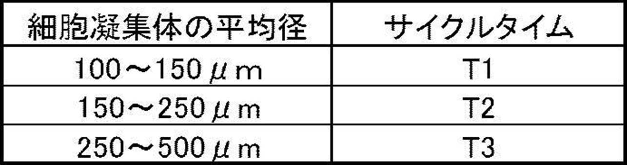
- step S5 the transfer control unit 40 derives the cycle time T corresponding to the average size of the cell aggregate derived in step S4 by referring to, for example, a table exemplified in Table 1 below.
- a cycle time T1 (for example, 6 hours to 12 hours) is assigned to the average size of the cell aggregates of 100 ⁇ m or more and less than 150 ⁇ m
- a cycle time T2 (for example, 4 hours to 10 hours) is assigned
- a cycle time T3 (2 hours to 8 hours) is assigned to the average size of the cell aggregates of 250 ⁇ m or more and less than 500 ⁇ m.
- T1 ⁇ T2 ⁇ T3.
- the transfer control unit 40 determines the cycle time T derived by referring to the table as a period until the next transfer of the cell suspension stored in the culture container 10A.
- the transfer control unit 40 also performs the same processing as described above when performing transfer control on the cell suspensions contained in the culture vessels 10B and 10C. If it is assumed that the average size of the cell aggregates contained in the cell suspension contained in each of the culture vessels 10A to 10C is substantially the same, the cell suspension is contained in any of the culture vessels 10A to 10C.
- the cycle time T derived based on the average size of the cell aggregates contained in the cell suspension thus obtained may be applied to the transfer control of the cell suspension contained in another culture container.
- the cell suspension is transferred between the culture containers 10A, 10B, and 10C and the culture container 10D, so that the cell suspension is transferred.
- the liquid is stirred. Thereby, nutrients and oxygen contained in the medium are distributed throughout the cells.
- damage to the cells can be reduced as compared with the case where stirring is performed using a stirring blade. That is, according to the cell culture device 1 according to the embodiment of the disclosed technology, it is possible to stir the cell suspension while suppressing damage to the cells.
- the monitor device 30 is disposed in the section X of the common flow channel 22, and during the transfer of the cell suspension, the transfer is performed.
- the cells (cell aggregates) contained in the target cell suspension are monitored by the monitor device 30. This makes it possible to observe all the cells (cell aggregates) contained in the cell suspension in parallel with the stirring treatment of the cell suspension.
- the cycle time T of the transfer control is determined according to the state of the cell (cell aggregate) monitored by the monitor device 30. More specifically, when the average size of the cell aggregate derived from the image captured by the imaging device 33 is relatively small, a relatively long period is set as the cycle time T of the transfer control. On the other hand, when the average size of the cell aggregate derived from the image captured by the imaging device 33 is relatively large, a relatively long period is set as the cycle time T of the transfer control. Cell aggregates of relatively small size have relatively low resistance to shear forces caused by the flow of the cell suspension and have relatively low nutrient and oxygen requirements.
- the result of monitoring the cells by the monitor device 30 may be used for purposes other than the setting of the cycle time T of the transfer control. For example, based on the image of the cell (cell aggregate) imaged by the imaging device 33, the timing at which the medium exchange or the subculture processing is performed may be determined. Further, the quality of the cells may be determined based on the image of the cells (cell aggregates) captured by the imaging device 33.
- the cell culture device 1 may include a heat transfer medium 80 in contact with each of the culture vessels 10A to 10D, and a heater (heat source) 81 for heating the heat transfer medium 80.
- the heat transfer medium 80 is configured to include a pair of plate members having a relatively high thermal conductivity such as metal or resin, and each of the culture vessels 10A to 10D is sandwiched between the pair of plate members. .
- the pair of plate members are configured so that the interval between them is constant.
- the heater 81 is attached to the surface of the heat transfer medium 80 opposite to the contact surface of the culture vessels 10A to 10D.
- the heat generated from the heater 80 is conducted through the heat transfer medium 80 to the cell suspension contained in the culture vessels 10A to 10D.
- the temperature of the heater 81 is controlled so that the cell suspension contained in the culture vessels 10A to 10D maintains a desired temperature (for example, 37 ° C.).
- the temperature of the cell suspension contained in the culture vessels 10A to 10D is adjusted to a desired temperature. It can be controlled and can form a favorable culture environment for the cells.
- the culture containers 10A to 10D have the form of a bag including, for example, a plastic film
- the inside of the culture container containing the cell suspension to be transferred is removed.
- the volume of the culture vessel expands. As a result, it becomes difficult to control the pressure inside the culture vessel, and it becomes difficult to control the discharge of the cell suspension.
- the expansion of the volume when the inside of the culture vessels 10A to 10D is pressurized can be restrained.
- the pressure inside the culture vessel is easily controlled, and the discharge control of the cell suspension is easily performed.
- FIG. 6 is a diagram illustrating an example of a configuration of a cell culture device 1A according to the second embodiment of the disclosed technology.
- the cell culture apparatus 1A includes a storage container 70 that stores the culture containers 10A to 10D.
- the storage container 70 has a function as an incubator, and has a temperature control mechanism for keeping the temperature inside the storage container 70 constant (for example, 37 ° C.).
- a gas containing oxygen and carbon dioxide whose composition is adjusted is introduced into the accommodation vessel 70. Is done. Thereby, oxygen and carbon dioxide necessary for cell growth can be taken into the cell suspension accommodated in the culture vessels 10A to 10D.
- the individual flow paths 21A to 21D, the common flow path 22, the gas introduction pipe 51, the gas discharge pipe 52, the monitor device 30, and the transfer control unit 40 are provided outside the container 70.
- the culture vessels 10A to 10D are housed inside the housing vessel 70 functioning as an incubator, and therefore, a preferable culture environment for the cells housed in the culture vessels 10A to 10D is obtained. Can be formed.
- FIG. 7 is a diagram illustrating an example of a configuration of a cell culture device 1B according to the third embodiment of the disclosed technology.
- the cell culture device 1B includes a culture vessel 10E having a larger volume than the culture vessels 10A to 10D.
- the culture vessel 10E is connected to the common flow path 22 via the individual flow path 21E.
- a valve 60E is provided in the middle of the individual flow path 21E.
- the gas introduction pipe 51 has an individual pipe 51E provided corresponding to the culture vessel 10E.
- a valve 61E is provided in the middle of the individual pipe 51E.
- the gas discharge pipe 52 has an individual pipe 52E provided corresponding to the culture vessel 10E.
- a valve 62E is provided in the middle of the individual pipe 52E.
- the monitor device 30 is provided in a section X of the common flow channel 22 between a connection portion with the individual flow channel 21D and a connection portion with the individual flow channel 21E.
- FIGS. 8A to 8E are diagrams illustrating an example of transfer control in the transfer control unit 40 of the cell culture device 1B according to the present embodiment.
- each of the culture vessels 10A to 10D contains a cell suspension containing a plurality of cells (cell aggregates), and the culture vessel 10E is empty. And In the culture vessels 10A to 10D, a plurality of cells (cell aggregates) are suspended in a culture medium in a stationary state. In the initial state, the valves 60A to 60E, 61
- a to 61E and 62A to 62E are respectively in the closed state.
- the transfer control unit 40 controls the valves 60A, 60B, 60E, 61A, 61B, and 62E to open by supplying a control signal Sc to each of the valves.
- gas is introduced into the culture vessels 10A and 10B via the gas introduction pipe 51, and the inside of the culture vessels 10A and 10B is pressurized.
- the inside of the culture vessels 10A and 10B is The contained cell suspension is transferred to the culture vessel 10E. While the cell suspension passes through the section X of the common flow channel 22, the cells contained in the cell suspension are monitored by the monitor device 30. That is, the imaging device 33 included in the monitor device 30 continuously images the cells contained in the cell suspension passing through the flow cell 31.
- the imaging device 33 captures, for example, all the cells (cell aggregates) included in the cell suspension to be transferred at an interval at which imaging can be performed.
- the image of the cell captured by the imaging device 33 is supplied to the transfer control unit 40.
- the transfer control unit 40 controls the valves 60A, 60B, 60E, 61A, 61B, and 62E to close.
- the transfer control unit 40 controls the valves 60A, 60B, 60E, 62A, 62B, and 61E to open.
- gas is introduced into the culture vessel 10E via the gas introduction pipe 51, and the inside of the culture vessel 10E is pressurized.
- FIG. 8C the cell suspension accommodated in the culture vessel 10E is released.
- the suspension is transferred to the culture vessels 10A and 10B. While the cell suspension passes through the section X of the common flow channel 22, the cells contained in the cell suspension are monitored by the monitor device 30.
- the transfer control unit 40 controls the valves 60A, 60B, 60E, 62A, 62B, and 61E to close.
- the transfer control unit 40 controls the transfer of the cell suspension contained in the culture vessels 10A and 10B to the culture vessels 10A and 10B after the cell suspension is transferred to the culture vessels 10E. Thereby, the transferred cell suspension is agitated, and nutrients and oxygen contained in the medium are distributed throughout the cells.
- the cell suspensions contained in the culture vessels 10A and 10B are mixed in the culture vessel 10E at the transfer destination.
- the case where the transfer of the cell suspension between the culture container 10A and the culture container 10E and the transfer of the cell suspension between the culture container 10B and the culture container 10E are performed simultaneously. However, these transfers may be performed sequentially.
- the monitoring of the cells by the monitor device 30 may be omitted.
- the transfer control unit 40 controls the valves 60C, 60D, 60E, 61C, 61D, and 62E to open by supplying a control signal Sc to each of the valves.
- gas is introduced into the culture vessels 10C and 10D via the gas introduction pipe 51, and the interior of the culture vessels 10C and 10D is pressurized, as shown in FIG. 8D.
- the contained cell suspension is transferred to the culture vessel 10E. While the cell suspension passes through the section X of the common flow channel 22, the cells contained in the cell suspension are monitored by the monitor device 30.
- the transfer control unit 40 controls the valves 60C, 60D, 60E, 61C, 61D, and 62E to close.
- the transfer control unit 40 controls the valves 60C, 60D, 60E, 62C, 62D, and 61E to open.
- gas is introduced into the culture vessel 10E via the gas introduction pipe 51, and the inside of the culture vessel 10D is pressurized.
- the cell suspension accommodated in the culture vessel 10E is removed.
- the suspension is transferred to the culture vessels 10C and 10D. While the cell suspension passes through the section X of the common flow channel 22, the cells contained in the cell suspension are monitored by the monitor device 30.
- the transfer control unit 40 controls the valves 60C, 60D, 60E, 62C, 62D, and 61E to close.
- the transfer control unit 40 controls the transfer of the cell suspensions contained in the culture vessels 10C and 10D to the culture vessels 10C and 10D after being transported to the culture vessels 10E. Thereby, the transferred cell suspension is agitated, and nutrients and oxygen contained in the medium are distributed throughout the cells.
- the cell suspensions contained in the culture vessels 10C and 10D are mixed in the culture vessel 10E at the transfer destination.
- the case where the transfer of the cell suspension between the culture container 10C and the culture container 10E and the transfer of the cell suspension between the culture container 10D and the culture container 10E are performed simultaneously. However, these transfers may be performed sequentially.
- the monitoring of the cells by the monitor device 30 may be omitted.
- FIG. 9 is a timing chart corresponding to a series of transfer controls shown in FIGS. 8A to 8E.
- FIG. 9 shows “presence” and “absence” of the cell suspension for each culture vessel.
- “presence” of the cell suspension corresponds to a high level
- “absence” of the cell suspension corresponds to a low level.
- the transfer control unit 40 repeats the transfer control in which each reciprocal transfer of the cell suspension between each of the culture vessels 10A to 10D and the culture vessel 10E is one set. carry out.
- the transfer control unit 40 determines a period (cycle time T) until the next transfer of the cell suspension contained in the culture vessels 10A to 10D based on the state of the cells monitored by the monitor device 30.
- the cell culture device 1C according to the present embodiment similarly to the cell culture device 1 according to the first embodiment (see FIG. 1), stirring of the cell suspension is performed while suppressing damage to the cells. Is possible. Further, according to the cell culture device 1C according to the present embodiment, the cell suspensions contained in the culture vessels 10A and 10B are mixed in the transfer destination culture vessel 10E, and are contained in the culture vessels 10C and 10D. The cell suspension is mixed in the transfer destination culture vessel 10E. Thereby, it is possible to suppress the variation in the quality of the cells between the culture vessels.
- FIGS. 10A to 10C are diagrams showing another example of transfer control in the transfer control unit 40 of the cell culture device 1B according to the present embodiment.
- each of the culture vessels 10A to 10D contains a cell suspension containing a plurality of cells (cell aggregates), and the culture vessel 10E is empty. And In the culture vessels 10A to 10D, a plurality of cells (cell aggregates) are suspended in a culture medium in a stationary state. In the initial state, the valves 60A to 60E, 61A to 61E, and 62A to 62E are assumed to be closed.
- the transfer control unit 40 controls the valves 60A to 60E, 61A to 61D, and 62E to open by supplying a control signal Sc to each of the valves.
- gas is introduced into the culture vessels 10A to 10D via the gas introduction pipe 51, and the inside of the culture vessels 10A to 10D is pressurized.
- FIG. 10B the inside of the culture vessels 10A to 10D is The contained cell suspension is transferred to the culture vessel 10E. While the cell suspension passes through the section X of the common flow channel 22, the cells contained in the cell suspension are monitored by the monitor device 30. That is, the imaging device 33 included in the monitor device 30 continuously images the cells contained in the cell suspension passing through the flow cell 31.
- the imaging device 33 captures, for example, all the cells (cell aggregates) included in the cell suspension to be transferred at an interval at which imaging can be performed.
- the image of the cell captured by the imaging device 33 is supplied to the transfer control unit 40.
- the transfer control unit 40 controls the valves 60A to 60E, 61A to 61D, and 62E to close.
- the transfer control unit 40 controls the valves 60A to 60E, 62A to 62D, and 61E to open. Thereby, gas is introduced into the culture vessel 10E via the gas introduction pipe 51, and the inside of the culture vessel 10E is pressurized. As shown in FIG. 10C, the cell suspension contained in the culture vessel 10E is removed. The suspension is transferred to the culture vessels 10A to 10D. While the cell suspension passes through the section X of the common flow channel 22, the cells contained in the cell suspension are monitored by the monitor device 30. After the transfer of the cell suspension is completed, the transfer control unit 40 controls the valves 60A to 60E, 62A to 62D, and 61E to close.
- the transfer control unit 40 controls the transfer of the cell suspension contained in the culture vessels 10A to 10D in the initial state to the culture vessels 10A after transferring the cell suspension to the culture vessel 10E. Thereby, the transferred cell suspension is agitated, and nutrients and oxygen contained in the medium are distributed throughout the cells. Further, in the initial state, the cell suspensions contained in the culture vessels 10A to 10D are mixed in the culture vessel 10E at the transfer destination. In the present embodiment, the case where the cell suspension is simultaneously transferred between each of the culture vessels 10A to 10D and the culture vessel 10E is exemplified, but these transfers may be performed sequentially. When returning the cell suspension from the culture vessel 10E to the culture vessels 10A to 10D, the monitoring of the cells by the monitor device 30 may be omitted.
- the transfer control unit 40 repeatedly performs the transfer control in which each one reciprocal transfer of the cell suspension between each of the culture vessels 10A to 10D and the culture vessel 10E is one set.
- the transfer control unit 40 determines a period (cycle time T) until the next transfer of the cell suspension contained in the culture vessels 10A to 10D based on the state of the cells monitored by the monitor device 30.
- FIGS. 11A to 11C are diagrams showing another example of transfer control in the transfer control unit 40 of the cell culture device 1B according to the present embodiment.
- each of the culture vessels 10A to 10D contains a cell suspension containing a plurality of cells (cell aggregates), and the culture vessel 10E is empty. And In the culture vessels 10A to 10D, a plurality of cells (cell aggregates) are suspended in a culture medium in a stationary state. In the initial state, the valves 60A to 60E, 61A to 61E, and 62A to 62E are assumed to be closed.
- the transfer control unit 40 controls the valves 60A to 60E, 61A to 61D, and 62E to open by supplying a control signal Sc to each of the valves.
- gas is introduced into the culture vessels 10A to 10D via the gas introduction pipe 51, and the interior of the culture vessels 10A to 10D is pressurized, as shown in FIG. 11B.
- the contained cell suspension is transferred to the culture vessel 10E.
- a part (for example, half) of the cell suspension contained in the culture vessels 10A to 10D is transferred to the culture vessel 10E. While the cell suspension passes through the section X of the common flow channel 22, the cells contained in the cell suspension are monitored by the monitor device 30.
- the imaging device 33 included in the monitor device 30 continuously images the cells contained in the cell suspension passing through the flow cell 31.
- the imaging device 33 captures, for example, all the cells (cell aggregates) included in the cell suspension to be transferred at an interval at which imaging can be performed.
- the image of the cell captured by the imaging device 33 is supplied to the transfer control unit 40.
- the transfer control unit 40 controls the valves 60A to 60E, 61A to 61D, and 62E to close.
- the transfer control unit 40 controls the valves 60A to 60E, 62A to 62D, and 61E to open.
- gas is introduced into the culture vessel 10E through the gas introduction pipe 51, and the inside of the culture vessel 10E is pressurized.
- FIG. 11C the cell suspension accommodated in the culture vessel 10E is removed.
- the suspension is transferred to the culture vessels 10A to 10D.
- the transfer control unit 40 controls the valves 60A to 60E, 62A to 62D, and 61E to close.
- the transfer control unit 40 repeatedly performs a process of transferring a part of the cell suspension contained in the culture vessels 10A to 10D to the culture vessel 10E, and then returning the cell suspension to the culture vessels 10A to 10D.
- the transfer control unit 40 performs transfer control for reciprocating the cell suspension contained in the culture vessels 10A to 10D with the culture vessel 10E a plurality of times in the initial state. Thereby, the transferred cell suspension is agitated, and nutrients and oxygen contained in the medium are distributed throughout the cells. Further, in the initial state, the cell suspensions contained in the culture vessels 10A to 10D are mixed in the culture vessel 10E at the transfer destination. In the present embodiment, the case where the cell suspensions are simultaneously transferred between the culture vessels 10A to 10D and the culture vessel 10E has been described, but these may be sequentially performed. When returning the cell suspension from the culture vessel 10E to the culture vessels 10A to 10D, the monitoring of the cells by the monitor device 30 may be omitted.
- the transfer control unit 40 repeatedly performs the transfer control in which the reciprocating movement of the cell suspension between each of the culture vessels 10A to 10D and the culture vessel 10E for a predetermined number of times is one set.
- the transfer control unit 40 determines a period (cycle time T) until the next transfer of the cell suspension contained in the culture vessels 10A to 10D based on the state of the cells monitored by the monitor device 30.
- FIG. 12 is a diagram illustrating an example of a configuration of a cell culture device 1C according to a fourth embodiment of the disclosed technology.
- the cell culture device 1C includes a plurality of culture vessels 10A, 10B, 10C, 10D, 10E, and 10F.
- the culture vessels 10A to 10F are connected to each other via a first flow path 20L and a second flow path 20R.
- the first flow path 20L includes individual flow paths 21A, 21B, 21C provided corresponding to each of the culture vessels 10A, 10B, 10C, and first flow of the individual flow paths 21A, 21B, 21C and the flow cell 31.
- a common channel 22L connected to the port 32a.
- Valves 60A, 60B, and 60C are provided in the middle of the individual flow paths 21A, 21B, and 21C, respectively.
- the second flow path 20R includes individual flow paths 21D, 21E, and 21F provided corresponding to the culture vessels 10D, 10E, and 10F, and second flow paths of the individual flow paths 21D, 21E, 21F, and the flow cell 31. And a common channel 22R connected to the port 32b. Valves 60D, 60E, and 60F are provided in the middle of the individual flow paths 21D, 21E, and 21F, respectively.
- FIGS. 13A to 13F are diagrams illustrating an example of transfer control in the transfer control unit 40 of the cell culture device 1C according to the present embodiment.
- a cell suspension containing a plurality of cells is contained in each of the culture vessels 10A to 10E, and the culture vessel 10F is empty. And A plurality of cells (cell aggregates) are suspended in a culture medium in the culture vessels 10A to 10E.
- the valves 60A to 60F, 61A to 61F, and 62A to 62F are each in a closed state.
- the transfer control unit 40 controls the valves 60A, 60F, 61A, and 62F to open by supplying a control signal Sc to each of the valves.
- gas is introduced into the culture vessel 10A via the gas introduction pipe 51, and the inside of the culture vessel 10A is pressurized.
- FIG. 13B the cell suspension housed inside the culture vessel 10A
- the suspension is transferred to the culture vessel 10F via the first flow path 20L and the second flow path 20R.
- the monitor device 30 that is, the imaging device 33 included in the monitor device 30 continuously images the cells contained in the cell suspension passing through the flow cell 31.
- the imaging device 33 captures, for example, all the cells (cell aggregates) included in the cell suspension to be transferred at an interval at which imaging can be performed. Note that the imaging device 33 may image a part of cells (cell aggregates) included in the cell suspension to be transferred.
- the image of the cell captured by the imaging device 33 is supplied to the transfer control unit 40. After the transfer of the cell suspension is completed, the transfer control unit 40 controls the valves 60A, 60F, 61A, and 62F to close.
- the transfer control unit 40 controls the transfer of the cell suspension contained in the culture container 10A to the culture container 10F. Thereby, the transferred cell suspension is agitated, and nutrients and oxygen contained in the medium are distributed throughout the cells.
- the transfer control unit 40 controls the valves 60D, 60A, 61D, and 62A to open by supplying the control signals Sc to the valves 60D, 60A, 61D, and 62A, respectively.
- gas is introduced into the culture vessel 10D via the gas introduction pipe 51, and the inside of the culture vessel 10D is pressurized.
- the cell suspension housed inside the culture vessel 10C The suspension is transferred to the culture vessel 10A via the first flow path 20L and the second flow path 20R. While the cell suspension passes through the section X between the first flow path 20L and the second flow path 20R, the cells included in the cell suspension are monitored by the monitor device 30. The image of the cell captured by the imaging device 33 is supplied to the transfer control unit 40. After the transfer of the cell suspension is completed, the transfer control unit 40 controls the valves 60D, 60A, 61D, and 62A to close.
- the transfer control unit 40 performs transfer control for transferring the cell suspension contained in the culture vessel 10D to the culture vessel 10A. Thereby, the transferred cell suspension is agitated, and nutrients and oxygen contained in the medium are distributed throughout the cells.
- the transfer control unit 40 controls the valves 60B, 60D, 61B, and 62D to open by supplying the control signals Sc to the valves 60B, 60D, 61B, and 62D, respectively.
- gas is introduced into the culture vessel 10B via the gas introduction pipe 51, and the inside of the culture vessel 10B is pressurized.
- the cell suspension contained in the culture vessel 10B is The suspension is transferred to the culture vessel 10D via the first flow path 20L and the second flow path 20R. While the cell suspension passes through the section X between the first flow path 20L and the second flow path 20R, the cells included in the cell suspension are monitored by the monitor device 30. The image of the cell captured by the imaging device 33 is supplied to the transfer control unit 40. After the transfer of the cell suspension is completed, the transfer control unit 40 controls the valves 60B, 60D, 61B, and 62D to close.
- the transfer control unit 40 performs the transfer control of transferring the cell suspension contained in the culture container 10B to the culture container 10D. Thereby, the transferred cell suspension is agitated, and nutrients and oxygen contained in the medium are distributed throughout the cells.
- the transfer control unit 40 controls the valves 60E, 60B, 61E, and 62B to open by supplying a control signal Sc to each of the valves.
- gas is introduced into the culture vessel 10E through the gas introduction pipe 51, and the inside of the culture vessel 10E is pressurized.
- the cell suspension accommodated in the culture vessel 10E is removed.
- the suspension is transferred to the culture vessel 10B via the second flow path 20R and the first flow path 20L.
- the cell suspension passes through the section X between the first flow path 20L and the second flow path 20R, the cells included in the cell suspension are monitored by the monitor device 30.
- the image of the cell captured by the imaging device 33 is supplied to the transfer control unit 40.
- the transfer control unit 40 controls the valves 60E, 60B, 61E, and 62B to close.
- the transfer control unit 40 performs the transfer control of transferring the cell suspension contained in the culture vessel 10E to the culture vessel 10B in the initial state. Thereby, the transferred cell suspension is agitated, and nutrients and oxygen contained in the medium are distributed throughout the cells.
- the transfer control unit 40 controls the valves 60C, 60E, 61C, and 62E to open by supplying a control signal Sc to each of the valves.
- gas is introduced into the culture vessel 10C via the gas introduction pipe 51, and the inside of the culture vessel 10C is pressurized.
- FIG. 13F the cell suspension accommodated in the culture vessel 10C is released.
- the suspension is transferred to the culture vessel 10E via the first flow path 20L and the second flow path 20R. While the cell suspension passes through the section X between the first flow path 20L and the second flow path 20R, the cells included in the cell suspension are monitored by the monitor device 30.
- the image of the cell captured by the imaging device 33 is supplied to the transfer control unit 40.
- the transfer control unit 40 controls the valves 60C, 60E, 61C, and 62E to close.
- the transfer control unit 40 controls the transfer of the cell suspension contained in the culture container 10C to the culture container 10E. Thereby, the transferred cell suspension is agitated, and nutrients and oxygen contained in the medium are distributed throughout the cells.
- FIG. 14 is a timing chart corresponding to a series of transfer controls shown in FIGS. 13A to 13G.
- FIG. 14 shows “presence” and “absence” of the cell suspension for each culture vessel.
- “presence” of the cell suspension corresponds to a high level
- “absence” of the cell suspension corresponds to a low level.
- the transfer control unit 40 repeatedly performs the transfer control in which each transfer of the cell suspension between the culture vessels 10A to 10F is set as one set.
- the transfer control unit 40 determines a period (cycle time T) until the next transfer of the cell suspension stored in the culture vessels 10A to 10F based on the state of the cells monitored by the monitor device 30.
- the cell culture device 1C similarly to the cell culture device 1 according to the first embodiment (see FIG. 1), stirring of the cell suspension is performed while suppressing damage to the cells. Is possible. Further, according to the cell culture device 1C according to the present embodiment, any one of the culture vessels 10A, 10B, and 10C connected to the first flow path 20L, and the culture vessel 10D connected to the second flow path 20R, One cycle of transfer control can be completed without reciprocating the cell suspension between any of 10E and 10F, so that the cell suspension can be efficiently stirred. Become.
- the case where the cell suspension contained in one culture vessel is transferred to another culture vessel is exemplified.
- the cell suspension contained in two or more culture vessels is transferred. May be transferred to one or more other culture vessels. Thereby, the cell suspensions accommodated in the two or more culture vessels may be mixed in the destination culture vessel.
Landscapes
- Chemical & Material Sciences (AREA)
- Health & Medical Sciences (AREA)
- Life Sciences & Earth Sciences (AREA)
- Engineering & Computer Science (AREA)
- Zoology (AREA)
- Wood Science & Technology (AREA)
- Bioinformatics & Cheminformatics (AREA)
- Organic Chemistry (AREA)
- Microbiology (AREA)
- Genetics & Genomics (AREA)
- Sustainable Development (AREA)
- Biotechnology (AREA)
- Biomedical Technology (AREA)
- Biochemistry (AREA)
- General Engineering & Computer Science (AREA)
- General Health & Medical Sciences (AREA)
- Analytical Chemistry (AREA)
- Clinical Laboratory Science (AREA)
- Physics & Mathematics (AREA)
- Thermal Sciences (AREA)
- Molecular Biology (AREA)
- Cell Biology (AREA)
- Computer Hardware Design (AREA)
- Apparatus Associated With Microorganisms And Enzymes (AREA)
Abstract
細胞培養装置は、3つ以上の複数の培養容器と、複数の培養容器を相互に接続する流路と、複数の培養容器のうちのいずれかに収容された細胞懸濁液を、流路を介して複数の培養容器のうちの他のいずれかに移送する移送制御を行う移送制御部と、を含む。
Description
本願は2018年7月5日出願の日本出願第2018-128455号の優先権を主張すると共に、その全文を参照により本明細書に援用する。
開示の技術は、細胞培養装置及び撹拌方法に関する。
開示の技術は、細胞培養装置及び撹拌方法に関する。
細胞培養装置に関する技術として、例えば、以下の技術が知られている。
例えば、特表2002-531114号公報には、培養菌を収容するための第1及び第2の培養容器、ガス源、培地源、殺菌剤源を含み、2つの培養容器の一方を培地源に、並びに2つの培養容器を互いに選択的に連結させ、他方の培養容器を殺菌剤源に選択的に連結させるための手段を有する導管系を含む装置が記載されている。
また、特開2015-188392号公報には、複数の培養容器に培地を供給する培地供給容器と、複数の培養容器として、培養面積の異なる培養容器を備え、複数の培養容器が、それぞれ他の容器との内容物の移送用のポートを一つ備え、培地供給容器に複数の培養容器が培養面積の小さい順にチューブを用いて接続された細胞培養システムが記載されている。
大量の細胞を培地とともに培養容器に収容して培養する場合、細胞の増殖に必要な栄養分及び酸素を、細胞全体に行き渡らせるために、細胞及び培地を含む細胞懸濁液を、撹拌翼を用いて撹拌することが行われている。しかしながら、撹拌翼を用いて細胞懸濁液を撹拌すると、細胞にせん断力が作用し、これによって細胞がダメージを受け、その結果、細胞の増殖性が低下したり、生存率が低下したりするおそれがある。
大量培養においては、培地中における栄養分及び酸素の偏りが生じやすくなることから、撹拌処理の重要性が高まる一方、撹拌に必要なエネルギーが大きくなるため、細胞へのダメージが大きくなるものと考えられる。
開示の技術は、上記の点に鑑みてなされたものであり、細胞懸濁液の撹拌を、細胞へのダメージを抑制しつつ行うことができる細胞培養装置及び撹拌方法を提供する。
開示の技術に係る細胞培養装置は、3つ以上の複数の培養容器と、複数の培養容器を相互に接続する流路と、複数の培養容器のうちのいずれかに収容された細胞懸濁液を、流路を介して前記複数の培養容器のうちの他のいずれかに移送する移送制御を行う移送制御部と、を含む。
これにより、細胞懸濁液の撹拌を、細胞へのダメージを抑制しつつ行うことが可能となる。
開示の技術に係る細胞培養装置は、複数の培養容器を収容する収容容器を更に含んでいてもよい。
収容容器がインキュベータとして機能することで、細胞にとって好ましい培養環境を形成することができる。
開示の技術の実施形態に係る細胞培養装置は、流路の途中に配置され、流路を通過する細胞懸濁液に含まれる細胞をモニタするモニタ装置を更に含んでいてもよい。
これにより、細胞懸濁液の撹拌処理に並行して、細胞懸濁液に含まれる細胞の全数観察が可能となる。
モニタ装置は、流路を通過する細胞懸濁液に含まれる細胞を撮像する撮像装置を含んでいてもよい。
これにより、細胞懸濁液の撹拌処理に並行して、細胞懸濁液に含まれる細胞の画像を取得することが可能である。
移送制御部は、移送制御において移送する細胞懸濁液を、流路の、モニタ装置が配置された部位を通過させることが好ましい。
これにより、細胞懸濁液の撹拌処理に並行して、細胞懸濁液に含まれる細胞の全数観察が可能となる。
移送制御部は、モニタ装置によってモニタされた細胞の状態に基づいて、当該細胞を含む細胞懸濁液の次の移送までの期間を定める
これにより、移送制御において、細胞の状態に応じた適切なサイクルタイムを設定することが可能となる。
培養容器は4つ以上であってもよい。モニタ装置は、第1の流通口及び第1の流通口に連通する第2の流通口を有するフローセルを含んでいてもよい。流路は、第1の流通口及び複数の培養容器のうちのいずれか2つ以上に接続された第1の流路と、第2の流通口及び複数の培養容器のうちの他の2つ以上に接続された第2の流路と、を含んでいてもよい。
これにより、培養容器間で細胞懸濁液を往復移動させることなく、1サイクルの移送制御を完了させることができるので、細胞懸濁液の撹拌処理を効率的に行うことが可能となる。
移送制御部は、移送制御において、複数の培養容器のうちのいずれか2つ以上に収容された細胞懸濁液を、複数の培養容器のうちの他の1つの培養容器に移送することにより混合してもよい。
これにより、複数の培養容器に収容された細胞懸濁液について、撹拌処理と並行して混合処理を行いことができるので、培養容器間での細胞の品質のばらつきを抑制することができる。
移送制御部は、移送制御において、培養容器の内部の圧力制御により細胞懸濁液の移送を行ってもよい。また、上記の圧力制御は、複数の培養容器のうちの移送対象の細胞懸濁液が収容された培養容器の内部への気体の導入により行われてもよい。
これにより、細胞懸濁液の移送を、細胞へのダメージを抑制しつつ行うことが可能である。
上記の圧力制御において、培養容器の内部に導入される気体として、温度及び組成が調整されたガスが用いられてもよい。
これにより、細胞にとって好ましい培養環境を形成することができる。
開示の技術に係る細胞培養装置は、培養容器の各々に接する伝熱媒体と、伝熱媒体を加熱する熱源と、を更に含んでいてもよい。
これにより、培養容器に収容された細胞懸濁液の温度を所望の温度に制御することでき、細胞にとって好ましい培養環境を形成することができる。
開示の技術に係る撹拌方法は、3つ以上の複数の培養容器と、複数の培養容器を相互に接続する流路と、を含む細胞培養装置の、複数の培養容器のうちのいずれかに収容された細胞懸濁を撹拌する撹拌方法であって、複数の培養容器のうちのいずれかに収容された細胞懸濁液を、流路を介して複数の培養容器のうちの他のいずれかに移送することにより移送対象の細胞懸濁液を撹拌することを含む。
これにより、細胞懸濁液の撹拌を、細胞へのダメージを抑制しつつ行うことが可能となる。
開示の技術に係る撹拌方法は、移送対象の細胞懸濁液が、流路を通過している間に、移送対象の細胞懸濁液に含まれる細胞をモニタすることを含んでいてもよい。
これにより、細胞懸濁液の撹拌処理に並行して、細胞懸濁液に含まれる細胞の全数観察が可能となる。
開示の技術に係る撹拌方法は、モニタされた細胞の状態に基づいて、当該細胞を含む細胞懸濁液の次の移送までの期間を定めることを含んでいてもよい。この場合、モニタされた細胞凝集体のサイズが大きい程、当該細胞凝集体を含む細胞懸濁液の次の移送までの期間を短くすることが好ましい。
これにより、細胞の状態に応じた適切なサイクルタイムを設定することが可能となる。
開示の技術に係る撹拌方法は、複数の培養容器のうちのいずれか2つ以上に収容された細胞懸濁液を、複数の培養容器のうちの他の1つの培養容器に移送することにより混合することを含む。
これにより、複数の培養容器に収容された細胞懸濁液について、撹拌処理と並行して混合処理を行いことができるので、培養容器間での細胞の品質のばらつきを抑制することができる。
開示の技術によれば、細胞懸濁液の撹拌を、細胞へのダメージを抑制しつつ行うことが可能となる。
以下、本開示の実施形態について図面を参照しつつ説明する。尚、各図面において、実質的に同一又は等価な構成要素又は部分には同一の参照符号を付している。
[第1の実施形態]
図1は、開示の技術の第1の実施形態に係る細胞培養装置1の構成の一例を示す図である。細胞培養装置1は、複数の培養容器10A、10B、10C、10D、モニタ装置30および移送制御部40を含んで構成されている。
図1は、開示の技術の第1の実施形態に係る細胞培養装置1の構成の一例を示す図である。細胞培養装置1は、複数の培養容器10A、10B、10C、10D、モニタ装置30および移送制御部40を含んで構成されている。
培養容器10A~10Dの各々は、複数の細胞及び細胞凝集体の少なくとも一方を含む細胞懸濁液が収容される容器である。培養容器10A~10Dの形態は、特に限定されず、例えば、ガラス製またはステンレス製の容器またはガス透過性を有するプラスチックフィルムを含んで構成されるバッグの形態を有する容器を使用することが可能である。なお、図1に示す例では、4つの培養容器10A~10Dを含む構成が例示されているが、細胞培養装置1は、3つまたは5つ以上の培養容器を含んでいてもよい。
培養容器10A~10Dは、流路20によって相互に接続されている。流路20は、培養容器10A~10Dの各々に対応して設けられた個別流路21A、21B、21C、21Dと、個別流路21A~21Dを相互に接続する共通流路22を含んで構成されている。個別流路21A~21Dの途中には、それぞれ、バルブ60A、60B、60C、60Dが設けられている。
細胞培養装置1は、培養容器10A~10Dの内部の圧力を調整するための圧力調整機構50を有する。圧力調整機構50は、培養容器10A~10Dの内部に導入されるガスが流通するガス導入配管51と、培養容器10A~10Dの内部から排出されたガスが流通するガス排出配管52とを有する。ガス導入配管51は、培養容器10A~10Dの各々に対応して設けられた個別配管51A、51B、51C、51Dを有する。個別配管51A~51Dの途中には、それぞれ、バルブ61A、61B、61C、61Dが設けられている。ガス排出配管52は、培養容器10A~10Dの各々に対応して設けられた個別配管52A、52B、52C、52Dを有する。個別配管52A~52Dの途中には、それぞれ、バルブ62A、62B、62C、62Dが設けられている。圧力調整機構50によって、培養容器10A~10Dの内部の圧力のバランスを調整することにより、培養容器10A~10Bの相互間で、これらに収容されている細胞懸濁液が移送される。なお、培養容器10A~10Dに導入するガスとして、温度及び組成が調整されたガスを用いてもよい。これにより、培養容器10A~10Dにおいて、好ましい培養環境を形成することが可能となる。
共通流路22の、個別流路21Cとの接続部と、個別流路21Dとの接続部との間の区間Xには、モニタ装置30が設けられている。モニタ装置30は、共通流路22の区間Xを通過する細胞懸濁液に含まれる細胞をモニタする。モニタ装置30は、フローセル31及び撮像装置33を含んで構成されている。
フローセル31は、その全体が、ガラスまたはプラスチック等の光透過性を有する材料で構成されている。フローセル31は、第1の流通口32aと、第1の流通口32aに連通する第2の流通口32bとを有している。
撮像装置33は、フローセル31の第1の流通口32aと第2の流通口32bとの間の領域に撮像視野が設定されており、第1の流通口32a及び第2の流通口32bのうちの一方から他方に向けて流れる細胞懸濁液に含まれる細胞(細胞凝集体)を、フローセル31越しに連続的に撮像する。撮像装置33によって撮像された複数の画像は、移送制御部40に送信される。
移送制御部40は、培養容器10A~10Dのうちのいずれかに収容された細胞懸濁液を、流路20を介して他のいずれかの培養容器に移送する移送制御を行う。移送制御部40は、バルブ60A~60D、バルブ61A~61D、バルブ62A~62Dに対して制御信号Scを供給して、これらのバルブを選択的に開閉することにより上記の移送制御を行う。移送制御によって移送される細胞懸濁液の液流によって、細胞懸濁液は撹拌され、培地に含まれる栄養分及び酸素を細胞全体に行き渡らせることができる。移送制御部40は、細胞懸濁液が、モニタ装置30が配置された共通流路22の区間Xを通過するように、移送制御を行う。
移送制御部40は、細胞懸濁液の移送を、培養容器10A~10D毎に、断続的に行う。移送制御部40は、モニタ装置30によってモニタされた細胞(細胞凝集体)の状態に基づいて、当該細胞(細胞凝集体)を含む細胞懸濁液の次の移送までの期間を定める。より具体的には、移送制御部40は、モニタ装置30を構成する撮像装置33から供給される複数の画像から、移送対象の細胞懸濁液に含まれる複数の細胞凝集体の平均サイズを導出する。移送制御部40は、導出した細胞凝集体の平均サイズに基づいて、当該細胞凝集体を含む細胞懸濁液の次の移送までの期間を定める。
以下において、移送制御部40における移送制御の一例を、図2A~図2Gを参照しつつ説明する。
初期状態において、図2Aに示すように、培養容器10A、10B、10Cには、それぞれ、複数の細胞(細胞凝集体)を含む細胞懸濁液が収容されており、培養容器10Dは空状態であるものとする。培養容器10A、10B、10Cには、複数の細胞(細胞凝集体)が、培地中に静止した状態で浮遊している。培地中に複数の細胞(細胞凝集体)を浮遊させるために、培地には増粘剤が添加されていてもよい。また、初期状態において、バルブ60A~60D、61A~61D、62A~62Dは、それぞれ閉状態であるものとする。
移送制御部40は、バルブ60A、60D、61A、62Dにそれぞれ制御信号Scを供給することで、これらのバルブを開状態に制御する。これにより、培養容器10Aの内部にガス導入配管51を介してガスが導入され、培養容器10Aの内部が加圧され、図2Bに示すように、培養容器10Aの内部に収容されている細胞懸濁液は、個別流路21A及び共通流路22を経由して、培養容器10Dに移送される。細胞懸濁液が、共通流路22の区間Xを通過する間、当該細胞懸濁液に含まれる細胞が、モニタ装置30によってモニタされる。すなわち、モニタ装置30を構成する撮像装置33は、フローセル31を通過する細胞懸濁液に含まれる細胞を連続的に撮像する。撮像装置33は、例えば、移送対象の細胞懸濁液に含まれる全ての細胞(細胞凝集体)を撮像可能な間隔で撮像を行う。なお、撮像装置33は、移送対象の細胞懸濁液に含まれる一部の細胞(細胞凝集体)を撮像してもよい。撮像装置33によって撮像された細胞の画像は、移送制御部40に供給される。移送制御部40は、細胞懸濁液の移送完了後、バルブ60A、60D、61A、62Dを閉状態に制御する。
次に、移送制御部40は、バルブ60A、60D、62A、61Dを開状態に制御する。これにより、培養容器10Dの内部にガス導入配管51を介してガスが導入され、培養容器10Dの内部が加圧され、図2Cに示すように、培養容器10Dの内部に収容されている細胞懸濁液は、個別流路21D及び共通流路22を経由して、培養容器10Aに移送される。細胞懸濁液が、共通流路22の区間Xを通過する間、当該細胞懸濁液に含まれる細胞が、モニタ装置30によってモニタされる。移送制御部40は、細胞懸濁液の移送完了後、バルブ60A、60D、62A、61Dを閉状態に制御する。
このように、移送制御部40は、初期状態において、培養容器10Aに収容されている細胞懸濁液を、培養容器10Dに移送した後、培養容器10Aに戻す移送制御を行う。これにより、移送された細胞懸濁液は撹拌され、培地に含まれる栄養分及び酸素が細胞全体に行き渡る。なお、培養容器10Dから培養容器10Aに細胞懸濁液を戻す場合には、モニタ装置30による細胞のモニタを省略してもよい。
次に、移送制御部40は、バルブ60B、60D、61B、62Dにそれぞれ制御信号Scを供給することで、これらのバルブを開状態に制御する。これにより、培養容器10Bの内部にガス導入配管51を介してガスが導入され、培養容器Bの内部が加圧され、図2Dに示すように、培養容器10Bの内部に収容されている細胞懸濁液は、個別流路21B及び共通流路22を経由して、培養容器10Dに移送される。細胞懸濁液が、共通流路22の区間Xを通過する間、当該細胞懸濁液に含まれる細胞が、モニタ装置30によってモニタされる。移送制御部40は、細胞懸濁液の移送完了後、バルブ60B、60D、61B、62Dを閉状態に制御する。
次に、移送制御部40は、バルブ60B、60D、62B、61Dを開状態に制御する。これにより、培養容器10Dの内部にガス導入配管51を介してガスが導入され、培養容器10Dの内部が加圧され、図2Eに示すように、培養容器10Dの内部に収容されている細胞懸濁液は、個別流路21D及び共通流路22を経由して、培養容器10Bに移送される。細胞懸濁液が、共通流路22の区間Xを通過する間、当該細胞懸濁液に含まれる細胞が、モニタ装置30によってモニタされる。移送制御部40は、細胞懸濁液の移送完了後、バルブ60B、60D、62B、61Dを閉状態に制御する。
このように、移送制御部40は、初期状態において、培養容器10Bに収容されている細胞懸濁液を、培養容器10Dに移送した後、培養容器10Bに戻す移送制御を行う。これにより、移送された細胞懸濁液は撹拌され、培地に含まれる栄養分及び酸素が細胞全体に行き渡る。なお、培養容器10Dから培養容器10Bに細胞懸濁液を戻す場合には、モニタ装置30による細胞のモニタを省略してもよい。
次に、移送制御部40は、バルブ60C、60D、61C、62Dにそれぞれ制御信号Scを供給することで、これらのバルブを開状態に制御する。これにより、培養容器10Cの内部にガス導入配管51を介してガスが導入され、培養容器Cの内部が加圧され、図2Fに示すように、培養容器10Cの内部に収容されている細胞懸濁液は、個別流路21C及び共通流路22を経由して、培養容器10Dに移送される。細胞懸濁液が、共通流路22の区間Xを通過する間、当該細胞懸濁液に含まれる細胞が、モニタ装置30によってモニタされる。移送制御部40は、細胞懸濁液の移送完了後、バルブ60C、60D、61C、62Dを閉状態に制御する。
次に、移送制御部40は、バルブ60C、60D、62C、61Dを開状態に制御する。これにより、培養容器10Dの内部にガス導入配管51を介してガスが導入され、培養容器10Dの内部が加圧され、図2Gに示すように、培養容器10Dの内部に収容されている細胞懸濁液は、個別流路21D及び共通流路22を経由して、培養容器10Cに移送される。細胞懸濁液が、共通流路22の区間Xを通過する間、当該細胞懸濁液に含まれる細胞が、モニタ装置30によってモニタされる。移送制御部40は、細胞懸濁液の移送完了後、バルブ60C、60D、62C、61Dを閉状態に制御する。
このように、移送制御部40は、初期状態において、培養容器10Cに収容されている細胞懸濁液を、培養容器10Dに移送した後、培養容器10Cに戻す移送制御を行う。これにより、移送された細胞懸濁液は撹拌され、培地に含まれる栄養分及び酸素が細胞全体に行き渡る。なお、培養容器10Dから培養容器10Cに細胞懸濁液を戻す場合には、モニタ装置30による細胞のモニタを省略してもよい。
以上のように、本実施形態に係る細胞培養装置1によれば、細胞懸濁液の移送は、培養容器毎に行われ、1つの培養容器に収容された細胞懸濁液の移送は、間欠的に行われる。
図3は、図2A~図2Gに示す一連の移送制御に対応するタイミングチャートである。図3には、細胞懸濁液の「存在」及び「不存在」が培養容器毎に示されている。図3において、細胞懸濁液の「存在」がハイレベルに対応し、細胞懸濁液の「不存在」がローレベルに対応する。図3に示すように、移送制御部40は、培養容器10A、10B、10Cの各々と、培養容器10Dとの間での細胞懸濁液の各1往復の移送を1セットとする移送制御を、繰り返し実施する。移送制御部40は、モニタ装置30によってモニタされた細胞(細胞凝集体)の状態に基づいて、培養容器10A、10B、10Cに収容されている細胞懸濁液の次の移送までの期間(サイクルタイムT)を定める。
図4は、移送制御部が、一例として、培養容器10Aに収容された細胞懸濁液について移送制御を行う場合に実施する処理の流れの一例を示すフローチャートである。
ステップS1において、移送制御部40は、バルブ60A、60D、61A、62Dにそれぞれ制御信号Scを供給することで、これらのバルブを開状態に制御する。これにより、培養容器10Aの内部に収容されている細胞懸濁液は、培養容器10Dに移送される。細胞懸濁液が、共通流路22の区間Xを通過する間、当該細胞懸濁液に含まれる細胞(細胞凝集体)が、撮像装置33によって撮像される。移送制御部40は、細胞懸濁液の移送完了後、バルブ60A、60D、61A、62Dを閉状態に制御する。
ステップS2において、移送制御部40は、撮像装置33によって撮像された細胞の複数の画像を取得する。
ステップS3において、移送制御部40は、バルブ60A、60D、62A、63Dを開状態に制御する。これにより、培養容器10Dの内部に収容されている細胞懸濁液は、培養容器10Aに移送される。移送制御部40は、細胞懸濁液の移送完了後、バルブ60A、60D、62A、61Dを閉状態に制御する。
ステップS4において、移送制御部40は、ステップS2において取得した複数の画像から、当該細胞懸濁液に含まれる細胞凝集体の平均サイズを導出する。例えば、当該細胞懸濁液に含まれる細胞凝集体の各々について、球形近似して得られる直径の算術平均値を、細胞凝集体の平均サイズとして適用してもよい。
ステップS5において、移送制御部40は、例えば、下記の表1に例示されるテーブルを参照することにより、ステップS4において導出した細胞凝集体の平均サイズに対応するサイクルタイムTを導出する。表1に例示されるテーブルにおいて、細胞凝集体の平均サイズ100μm以上150μm未満に対してサイクルタイムT1(例えば6時間~12時間)が割り当てられ、細胞凝集体の平均サイズ150μm以上250μm未満に対してサイクルタイムT2(例えば4時間~10時間)が割り当てられ、細胞凝集体の平均サイズ250μm以上500μm未満に対してサイクルタイムT3(2時間~8時間)が割り当てられている。なお、T1≧T2≧T3である。移送制御部40は、テーブルを参照することにより導出したサイクルタイムTを、培養容器10Aに収容された細胞懸濁液の次の移送までの期間として定める。
移送制御部40は、培養容器10B及び10Cに収容された細胞懸濁液について移送制御を行う場合についても、上記と同様の処理を実施する。なお、培養容器10A~10Cの各々に収容される細胞懸濁液に含まれる細胞凝集体の平均サイズが概ね同じであることが想定される場合には、培養容器10A~10Cのいずれかに収容された細胞懸濁液に含まれる細胞凝集体の平均サイズに基づいて導出したサイクルタイムTを、他の培養容器に収容された細胞懸濁液の移送制御において適用してもよい。
以上のように、開示の技術の実施形態に係る細胞培養装置1によれば、培養容器10A、10B、10Cと、培養容器10Dとの間で細胞懸濁が移送されることで、細胞懸濁液が撹拌される。これにより、培地に含まれる栄養分及び酸素が細胞全体に行き渡る。細胞懸濁液の撹拌を、細胞懸濁液の移送によって行うことで、撹拌翼を用いて撹拌を行う場合と比較して、細胞へのダメージを小さくすることができる。すなわち、開示の技術の実施形態に係る細胞培養装置1によれば、細胞懸濁液の撹拌を、細胞へのダメージを抑制しつつ行うことが可能となる。
また、開示の技術の実施形態に係る細胞培養装置1によれば、モニタ装置30が、共通流路22の区間Xに配置されており、細胞懸濁液の移送が行われている間、移送対象の細胞懸濁液に含まれる細胞(細胞凝集体)がモニタ装置30によってモニタされる。これにより、細胞懸濁液の撹拌処理と並行して、当該細胞懸濁液に含まれる細胞(細胞凝集体)の全数観察を行うことが可能となる。
また、モニタ装置30によってモニタされた細胞(細胞凝集体)の状態に応じて移送制御のサイクルタイムTが定められる。より具体的には、撮像装置33によって撮像された画像から導出された細胞凝集体の平均サイズが相対的に小さい場合には、移送制御のサイクルタイムTとして相対的に長い期間が設定される。一方、撮像装置33によって撮像された画像から導出された細胞凝集体の平均サイズが相対的に大きい場合には、移送制御のサイクルタイムTとして相対的に長い期間が設定される。サイズが相対的に小さい細胞凝集体は、細胞懸濁液の液流によって生じるせん断力に対する耐性が相対的に低く、且つ栄養分及び酸素の必要量は相対的に少ない。一方、サイズが相対的に大きい細胞凝集体は、細胞懸濁液の液流によって生じるせん断力に対する耐性が相対的に高く、且つ栄養分及び酸素の必要量は相対的に多い。従って、上記のように、細胞凝集体の平均サイズに応じて移送制御のサイクルタイムTを定めることで、細胞凝集体のサイズに適した移送制御(撹拌処理)のサイクルタイムTの設定を行うことができる。
なお、モニタ装置30による細胞のモニタ結果を、移送制御のサイクルタイムTの設定以外の目的で利用してもよい。例えば、撮像装置33によって撮像された細胞(細胞凝集体)の画像に基づいて、培地交換または継代処理を実施するタイミングを定めてもよい。また、撮像装置33によって撮像された細胞(細胞凝集体)の画像に基づいて、細胞の良否判定を行ってもよい。
また、細胞培養装置1は、図5に示すように、培養容器10A~10Dの各々と接する伝熱媒体80と、伝熱媒体80を加熱するヒータ(熱源)81とを備えていてもよい。伝熱媒体80は、金属または樹脂等の熱伝導率の比較的高い一対の板状部材を含んで構成されており、培養容器10A~10Dの各々は、一対の板状部材の間に挟まれる。一対の板状部材は、相互の間隔が一定となるように構成されている。ヒータ81は、伝熱媒体80の、培養容器10A~10Dの接触面とは反対側の面に取り付けられている。ヒータ80から発せられる熱は、伝熱媒体80を介して、培養容器10A~10Dの内部に収容された細胞懸濁液に伝導する。ヒータ81の温度は、培養容器10A~10Dに収容された細胞懸濁液が所望の温度(例えば37℃)を維持するように制御される。
このように、培養容器10A~10Dを、伝熱媒体80を構成する一対の板状部材の間に挟むことで、培養容器10A~10Dに収容された細胞懸濁液の温度を所望の温度に制御することでき、細胞にとって好ましい培養環境を形成することができる。また、培養容器10A~10Dが、例えばプラスチックフィルムを含んで構成されるバッグの形態を有する場合、細胞懸濁液を移送する際に、移送対象の細胞懸濁液を収容した培養容器の内部を加圧すると、当該培養容器の容積が拡大する。その結果、培養容器の内部の圧力制御が困難となり、細胞懸濁液の払い出し制御が困難となる。培養容器10A~10Dを、伝熱媒体80を構成する一対の板状部材の間に挟むことで、培養容器10A~10Dの内部を加圧した場合の容積の拡大を拘束することができるので、培養容器の内部の圧力制御が容易となり、細胞懸濁液の払い出し制御が容易となる。
[第2の実施形態]
図6は、開示の技術の第2の実施形態に係る細胞培養装置1Aの構成の一例を示す図である。
図6は、開示の技術の第2の実施形態に係る細胞培養装置1Aの構成の一例を示す図である。
細胞培養装置1Aは、培養容器10A~10Dを収容する収容容器70を含んでいる。収容容器70は、インキュベータとしての機能を備えており、収容容器70の内部の温度を一定(例えば37℃)に保持する温度制御機構を有する。また、培養容器10A~10Dがガス透過性を有するプラスチックフィルムを含んで構成されるバッグの形態を有する場合、収容容器70の内部には、組成が調整された酸素及び二酸化炭素を含むガスが導入される。これにより、培養容器10A~10D内に収容された細胞懸濁液に、細胞の増殖に必要な酸素及び二酸化炭素を取り込むことができる。なお、本実施形態において、個別流路21A~21D、共通流路22、ガス導入配管51、ガス排出配管52、モニタ装置30及び移送制御部40は、収容容器70の外部に設けられている。
本実施形態に係る細胞培養装置1Aによれば、培養容器10A~10Dは、インキュベータとして機能する収容容器70の内部に収容されるので、培養容器10A~10Dに収容された細胞にとって好ましい培養環境を形成することができる。
[第3の実施形態]
図7は、開示の技術の第3の実施形態に係る細胞培養装置1Bの構成の一例を示す図である。
図7は、開示の技術の第3の実施形態に係る細胞培養装置1Bの構成の一例を示す図である。
細胞培養装置1Bは、培養容器10A~10Dの容積よりも大きい容積を有する培養容器10Eを備える。培養容器10Eは、個別流路21Eを介して共通流路22に接続されている。個別流路21Eの途中には、バルブ60Eが設けられている。ガス導入配管51は、培養容器10Eに対応して設けられた個別配管51Eを有する。個別配管51Eの途中にはバルブ61Eが設けられている。ガス排出配管52は、培養容器10Eに対応して設けられた個別配管52Eを有する。個別配管52Eの途中にはバルブ62Eが設けられている。モニタ装置30は、共通流路22の、個別流路21Dとの接続部と、個別流路21Eとの接続部との間の区間Xに設けられている。
図8A~図8Eは、本実施形態に係る細胞培養装置1Bの移送制御部40における移送制御の一例を示す図である。
初期状態において、図8Aに示すように、培養容器10A~10Dには、それぞれ、複数の細胞(細胞凝集体)を含む細胞懸濁液が収容されており、培養容器10Eは空状態であるものとする。培養容器10A~10Dには、複数の細胞(細胞凝集体)が、培地中に静止した状態で浮遊している。また、初期状態において、バルブ60A~60E、61
A~61E、62A~62Eは、それぞれ閉状態であるものとする。
移送制御部40は、バルブ60A、60B、60E、61A、61B、62Eにそれぞれ制御信号Scを供給することで、これらのバルブを開状態に制御する。これにより、培養容器10A及び10Bの内部にガス導入配管51を介してガスが導入され、培養容器10A及び10Bの内部が加圧され、図8Bに示すように、培養容器10A及び10Bの内部に収容されている細胞懸濁液は、培養容器10Eに移送される。細胞懸濁液が、共通流路22の区間Xを通過する間、当該細胞懸濁液に含まれる細胞が、モニタ装置30によってモニタされる。すなわち、モニタ装置30を構成する撮像装置33は、フローセル31を通過する細胞懸濁液に含まれる細胞を連続的に撮像する。撮像装置33は、例えば、移送対象の細胞懸濁液に含まれる全ての細胞(細胞凝集体)を撮像可能な間隔で撮像を行う。撮像装置33によって撮像された細胞の画像は、移送制御部40に供給される。移送制御部40は、細胞懸濁液の移送完了後、バルブ60A、60B、60E、61A、61B、62Eを閉状態に制御する。
次に、移送制御部40は、バルブ60A、60B、60E、62A、62B、61Eを開状態に制御する。これにより、培養容器10Eの内部にガス導入配管51を介してガスが導入され、培養容器10Eの内部が加圧され、図8Cに示すように、培養容器10Eの内部に収容されている細胞懸濁液は、培養容器10A及び10Bに移送される。細胞懸濁液が、共通流路22の区間Xを通過する間、当該細胞懸濁液に含まれる細胞が、モニタ装置30によってモニタされる。移送制御部40は、細胞懸濁液の移送完了後、バルブ60A、60B、60E、62A、62B、61Eを閉状態に制御する。
このように、移送制御部40は、初期状態において、培養容器10A及び10Bに収容されている細胞懸濁液を、培養容器10Eに移送した後、培養容器10A及び10Bに戻す移送制御を行う。これにより、移送された細胞懸濁液は撹拌され、培地に含まれる栄養分及び酸素が細胞全体に行き渡る。また、初期状態において、培養容器10A及び10Bに収容されている細胞懸濁液は、移送先の培養容器10E内において混合される。なお、本実施形態では、培養容器10Aと培養容器10Eとの間での細胞懸濁液の移送と、培養容器10Bと培養容器10Eとの間での細胞懸濁液の移送とを同時に行う場合を例示したが、これらの移送を順次行ってもよい。また、培養容器10Eから培養容器10A及び10Bに細胞懸濁液を戻す場合には、モニタ装置30による細胞のモニタを省略してもよい。
次に、移送制御部40は、バルブ60C、60D、60E、61C、61D、62Eにそれぞれ制御信号Scを供給することで、これらのバルブを開状態に制御する。これにより、培養容器10C及び10Dの内部にガス導入配管51を介してガスが導入され、培養容器10C及び10Dの内部が加圧され、図8Dに示すように、培養容器10C及び10Dの内部に収容されている細胞懸濁液は、培養容器10Eに移送される。細胞懸濁液が、共通流路22の区間Xを通過する間、当該細胞懸濁液に含まれる細胞が、モニタ装置30によってモニタされる。移送制御部40は、細胞懸濁液の移送完了後、バルブ60C、60D、60E、61C、61D、62Eを閉状態に制御する。
次に、移送制御部40は、バルブ60C、60D、60E、62C、62D、61Eを開状態に制御する。これにより、培養容器10Eの内部にガス導入配管51を介してガスが導入され、培養容器10Dの内部が加圧され、図8Eに示すように、培養容器10Eの内部に収容されている細胞懸濁液は、培養容器10C及び10Dに移送される。細胞懸濁液が、共通流路22の区間Xを通過する間、当該細胞懸濁液に含まれる細胞が、モニタ装置30によってモニタされる。移送制御部40は、細胞懸濁液の移送完了後、バルブ60C、60D、60E、62C、62D、61Eを閉状態に制御する。
このように、移送制御部40は、初期状態において、培養容器10C及び10Dに収容されている細胞懸濁液を、培養容器10Eに移送した後、培養容器10C及び10Dに戻す移送制御を行う。これにより、移送された細胞懸濁液は撹拌され、培地に含まれる栄養分及び酸素が細胞全体に行き渡る。また、初期状態において、培養容器10C及び10Dに収容されている細胞懸濁液は、移送先の培養容器10E内において混合される。なお、本実施形態では、培養容器10Cと培養容器10Eとの間での細胞懸濁液の移送と、培養容器10Dと培養容器10Eとの間での細胞懸濁液の移送とを同時に行う場合を例示したが、これらの移送を順次行ってもよい。また、培養容器10Eから培養容器10C及び10Dに細胞懸濁液を戻す場合には、モニタ装置30による細胞のモニタを省略してもよい。
図9は、図8A~図8Eに示す一連の移送制御に対応するタイミングチャートである。図9には、細胞懸濁液の「存在」及び「不存在」が、培養容器毎に示されている。図9において、細胞懸濁液の「存在」がハイレベルに対応し、細胞懸濁液の「不存在」がローレベルに対応する。
図9に示すように、移送制御部40は、培養容器10A~10Dの各々と、培養容器10Eとの間での細胞懸濁液の各1往復の移送を1セットとする移送制御を、繰り返し実施する。移送制御部40は、モニタ装置30によってモニタされた細胞の状態に基づいて、培養容器10A~10Dに収容された細胞懸濁液の次の移送までの期間(サイクルタイムT)を定める。
本実施形態に係る細胞培養装置1Cによれば、第1の実施形態に係る細胞培養装置1(図1参照)と同様、細胞懸濁液の撹拌を、細胞へのダメージを抑制しつつ行うことが可能である。また、本実施形態に係る細胞培養装置1Cによれば、培養容器10A及び10Bに収容されている細胞懸濁液が移送先の培養容器10Eにおいて混合され、培養容器10C及び10Dに収容されている細胞懸濁液が移送先の培養容器10Eにおいて混合される。これにより、培養容器間での細胞の品質のばらつきを抑制することが可能となる。
図10A~図10Cは、本実施形態に係る細胞培養装置1Bの移送制御部40における移送制御の他の例を示す図である。
初期状態において、図10Aに示すように、培養容器10A~10Dには、それぞれ、複数の細胞(細胞凝集体)を含む細胞懸濁液が収容されており、培養容器10Eは空状態であるものとする。培養容器10A~10Dには、複数の細胞(細胞凝集体)が、培地中に静止した状態で浮遊している。また、初期状態において、バルブ60A~60E、61A~61E、62A~62Eは、それぞれ閉状態であるものとする。
移送制御部40は、バルブ60A~60E、61A~61D、62Eにそれぞれ制御信号Scを供給することで、これらのバルブを開状態に制御する。これにより、培養容器10A~10Dの内部にガス導入配管51を介してガスが導入され、培養容器10A~10Dの内部が加圧され、図10Bに示すように、培養容器10A~10Dの内部に収容されている細胞懸濁液は、培養容器10Eに移送される。細胞懸濁液が、共通流路22の区間Xを通過する間、当該細胞懸濁液に含まれる細胞が、モニタ装置30によってモニタされる。すなわち、モニタ装置30を構成する撮像装置33は、フローセル31を通過する細胞懸濁液に含まれる細胞を連続的に撮像する。撮像装置33は、例えば、移送対象の細胞懸濁液に含まれる全ての細胞(細胞凝集体)を撮像可能な間隔で撮像を行う。撮像装置33によって撮像された細胞の画像は、移送制御部40に供給される。移送制御部40は、細胞懸濁液の移送完了後、バルブ60A~60E、61A~61D、62Eを閉状態に制御する。
次に、移送制御部40は、バルブ60A~60E、62A~62D、61Eを開状態に制御する。これにより、培養容器10Eの内部にガス導入配管51を介してガスが導入され、培養容器10Eの内部が加圧され、図10Cに示すように、培養容器10Eの内部に収容されている細胞懸濁液は、培養容器10A~10Dに移送される。細胞懸濁液が、共通流路22の区間Xを通過する間、当該細胞懸濁液に含まれる細胞が、モニタ装置30によってモニタされる。移送制御部40は、細胞懸濁液の移送完了後、バルブ60A~60E、62A~62D、61Eを閉状態に制御する。
このように、移送制御部40は、初期状態において培養容器10A~10Dに収容されている細胞懸濁液を、培養容器10Eに移送した後、培養容器10A~10Dに戻す移送制御を行う。これにより、移送された細胞懸濁液は撹拌され、培地に含まれる栄養分及び酸素が細胞全体に行き渡る。更に、初期状態において、培養容器10A~10Dに収容されている細胞懸濁液は、移送先の培養容器10E内において混合される。なお、本実施形態では、培養容器10A~10Dの各々と培養容器10Eとの間での細胞懸濁液の移送を同時に行う場合を例示したが、これらの移送を順次行ってもよい。また、培養容器10Eから培養容器10A~10Dに細胞懸濁液を戻す場合には、モニタ装置30による細胞のモニタを省略してもよい。
移送制御部40は、培養容器10A~10Dの各々と、培養容器10Eとの間での細胞懸濁液の各1往復の移送を1セットとする移送制御を、繰り返し実施する。移送制御部40は、モニタ装置30によってモニタされた細胞の状態に基づいて、培養容器10A~10Dに収容された細胞懸濁液の次の移送までの期間(サイクルタイムT)を定める。
図10A~図10Cに示す移送制御によれば、培養容器10A~10Dに収容されている全ての細胞懸濁液が、移送先の培養容器10Eにおいて混合される。これにより、培養容器間での細胞の品質のばらつきを抑制する効果を更に高めることができる。
図11A~図11Cは、本実施形態に係る細胞培養装置1Bの移送制御部40における移送制御の他の例を示す図である。
初期状態において、図11Aに示すように、培養容器10A~10Dには、それぞれ、複数の細胞(細胞凝集体)を含む細胞懸濁液が収容されており、培養容器10Eは空状態であるものとする。培養容器10A~10Dには、複数の細胞(細胞凝集体)が、培地中に静止した状態で浮遊している。また、初期状態において、バルブ60A~60E、61A~61E、62A~62Eは、それぞれ閉状態であるものとする。
移送制御部40は、バルブ60A~60E、61A~61D、62Eにそれぞれ制御信号Scを供給することで、これらのバルブを開状態に制御する。これにより、培養容器10A~10Dの内部にガス導入配管51を介してガスが導入され、培養容器10A~10Dの内部が加圧され、図11Bに示すように、培養容器10A~10Dの内部に収容されている細胞懸濁液は、培養容器10Eに移送される。本実施形態では、培養容器10A~10Dに収容されている細胞懸濁液の一部(例えば半分)が、それぞれ培養容器10Eに移送される。細胞懸濁液が、共通流路22の区間Xを通過する間、当該細胞懸濁液に含まれる細胞が、モニタ装置30によってモニタされる。すなわち、モニタ装置30を構成する撮像装置33は、フローセル31を通過する細胞懸濁液に含まれる細胞を連続的に撮像する。撮像装置33は、例えば、移送対象の細胞懸濁液に含まれる全ての細胞(細胞凝集体)を撮像可能な間隔で撮像を行う。撮像装置33によって撮像された細胞の画像は、移送制御部40に供給される。移送制御部40は、細胞懸濁液の移送完了後、バルブ60A~60E、61A~61D、62Eを閉状態に制御する。
次に、移送制御部40は、バルブ60A~60E、62A~62D、61Eを開状態に制御する。これにより、培養容器10Eの内部にガス導入配管51を介してガスが導入され、培養容器10Eの内部が加圧され、図11Cに示すように、培養容器10Eの内部に収容されている細胞懸濁液は、培養容器10A~10Dに移送される。細胞懸濁液が、共通流路22の区間Xを通過する間、当該細胞懸濁液に含まれる細胞が、モニタ装置30によってモニタされる。移送制御部40は、細胞懸濁液の移送完了後、バルブ60A~60E、62A~62D、61Eを閉状態に制御する。移送制御部40は、培養容器10A~10Dに収容されている細胞懸濁液の一部を培養容器10Eに移送した後、培養容器10A~10Dに戻す処理を、繰り返し実施する。
このように、移送制御部40は、初期状態において培養容器10A~10Dに収容されている細胞懸濁液を、培養容器10Eとの間で複数回に亘り往復させる移送制御を行う。これにより、移送された細胞懸濁液は撹拌され、培地に含まれる栄養分及び酸素が細胞全体に行き渡る。更に、初期状態において、培養容器10A~10Dに収容されている細胞懸濁液は、移送先の培養容器10E内において混合される。なお、本実施形態では、培養容器10A~10Dと培養容器10Eとの間での細胞懸濁液の移送を同時に行う場合を例示したが、これらの移送を順次行ってもよい。また、培養容器10Eから培養容器10A~10Dに細胞懸濁液を戻す場合には、モニタ装置30による細胞のモニタを省略してもよい。
移送制御部40は、培養容器10A~10Dの各々と、培養容器10Eとの間での細胞懸濁液の所定回数に亘る往復移動を1セットとする移送制御を、繰り返し実施する。移送制御部40は、モニタ装置30によってモニタされた細胞の状態に基づいて、培養容器10A~10Dに収容された細胞懸濁液の次の移送までの期間(サイクルタイムT)を定める。
[第4の実施形態]
図12は、開示の技術の第4の実施形態に係る細胞培養装置1Cの構成の一例を示す図である。細胞培養装置1Cは、複数の培養容器10A、10B、10C、10D、10E及び10Fを備えている。
図12は、開示の技術の第4の実施形態に係る細胞培養装置1Cの構成の一例を示す図である。細胞培養装置1Cは、複数の培養容器10A、10B、10C、10D、10E及び10Fを備えている。
培養容器10A~10Fは、第1の流路20L及び第2の流路20Rを介して相互に接続されている。第1の流路20Lは、培養容器10A、10B、10Cの各々に対応して設けられた個別流路21A、21B、21Cと、個別流路21A、21B、21C及びフローセル31の第1の流通口32aに接続された共通流路22Lと、を含んで構成されている。個別流路21A、21B、21Cの途中には、それぞれ、バルブ60A、60B、60Cが設けられている。第2の流路20Rは、培養容器10D、10E、10Fの各々に対応して設けられた個別流路21D、21E、21Fと、個別流路21D、21E、21F及びフローセル31の第2の流通口32bに接続された共通流路22Rと、を含んで構成されている。個別流路21D、21E、21Fの途中には、それぞれ、バルブ60D、60E、60Fが設けられている。
図13A~図13Fは、本実施形態に係る細胞培養装置1Cの移送制御部40における移送制御の一例を示す図である。
初期状態において、図13Aに示すように、培養容器10A~10Eには、それぞれ、複数の細胞(細胞凝集体)を含む細胞懸濁液が収容されており、培養容器10Fは空状態であるものとする。培養容器10A~10Eには、複数の細胞(細胞凝集体)が、培地中に静止した状態で浮遊している。また、初期状態において、バルブ60A~60F、61A~61F、62A~62Fは、それぞれ閉状態であるものとする。
移送制御部40は、バルブ60A、60F、61A、62Fにそれぞれ制御信号Scを供給することで、これらのバルブを開状態に制御する。これにより、培養容器10Aの内部にガス導入配管51を介してガスが導入され、培養容器10Aの内部が加圧され、図13Bに示すように、培養容器10Aの内部に収容されている細胞懸濁液は、第1の流路20L及び第2の流路20Rを経由して、培養容器10Fに移送される。細胞懸濁液が、第1の流路20Lと第2の流路20Rとの間の区間Xを通過する間、当該細胞懸濁液に含まれる細胞が、モニタ装置30によってモニタされる。すなわち、モニタ装置30を構成する撮像装置33は、フローセル31を通過する細胞懸濁液に含まれる細胞を連続的に撮像する。撮像装置33は、例えば、移送対象の細胞懸濁液に含まれる全ての細胞(細胞凝集体)を撮像可能な間隔で撮像を行う。なお、撮像装置33は、移送対象の細胞懸濁液に含まれる一部の細胞(細胞凝集体)を撮像してもよい。撮像装置33によって撮像された細胞の画像は、移送制御部40に供給される。移送制御部40は、細胞懸濁液の移送完了後、バルブ60A、60F、61A、62Fを閉状態に制御する。
このように、移送制御部40は、初期状態において、培養容器10Aに収容されている細胞懸濁液を、培養容器10Fに移送する移送制御を行う。これにより、移送された細胞懸濁液は撹拌され、培地に含まれる栄養分及び酸素が細胞全体に行き渡る。
次に、移送制御部40は、バルブ60D、60A、61D、62Aにそれぞれ制御信号Scを供給することで、これらのバルブを開状態に制御する。これにより、培養容器10Dの内部にガス導入配管51を介してガスが導入され、培養容器10Dの内部が加圧され、図13Cに示すように、培養容器10Cの内部に収容されている細胞懸濁液は、第1の流路20L及び第2の流路20Rを経由して、培養容器10Aに移送される。細胞懸濁液が、第1の流路20Lと第2の流路20Rとの間の区間Xを通過する間、当該細胞懸濁液に含まれる細胞が、モニタ装置30によってモニタされる。撮像装置33によって撮像された細胞の画像は、移送制御部40に供給される。移送制御部40は、細胞懸濁液の移送完了後、バルブ60D、60A、61D、62Aを閉状態に制御する。
このように、移送制御部40は、初期状態において、培養容器10Dに収容されている細胞懸濁液を、培養容器10Aに移送する移送制御を行う。これにより、移送された細胞懸濁液は撹拌され、培地に含まれる栄養分及び酸素が細胞全体に行き渡る。
次に、移送制御部40は、バルブ60B、60D、61B、62Dにそれぞれ制御信号Scを供給することで、これらのバルブを開状態に制御する。これにより、培養容器10Bの内部にガス導入配管51を介してガスが導入され、培養容器10Bの内部が加圧され、図13Dに示すように、培養容器10Bの内部に収容されている細胞懸濁液は、第1の流路20L及び第2の流路20Rを経由して、培養容器10Dに移送される。細胞懸濁液が、第1の流路20Lと第2の流路20Rとの間の区間Xを通過する間、当該細胞懸濁液に含まれる細胞が、モニタ装置30によってモニタされる。撮像装置33によって撮像された細胞の画像は、移送制御部40に供給される。移送制御部40は、細胞懸濁液の移送完了後、バルブ60B、60D、61B、62Dを閉状態に制御する。
このように、移送制御部40は、初期状態において、培養容器10Bに収容されている細胞懸濁液を、培養容器10Dに移送する移送制御を行う。これにより、移送された細胞懸濁液は撹拌され、培地に含まれる栄養分及び酸素が細胞全体に行き渡る。
次に、移送制御部40は、バルブ60E、60B、61E、62Bにそれぞれ制御信号Scを供給することで、これらのバルブを開状態に制御する。これにより、培養容器10Eの内部にガス導入配管51を介してガスが導入され、培養容器10Eの内部が加圧され、図13Eに示すように、培養容器10Eの内部に収容されている細胞懸濁液は、第2の流路20R及び第1の流路20Lを経由して、培養容器10Bに移送される。細胞懸濁液が、第1の流路20Lと第2の流路20Rとの間の区間Xを通過する間、当該細胞懸濁液に含まれる細胞が、モニタ装置30によってモニタされる。撮像装置33によって撮像された細胞の画像は、移送制御部40に供給される。移送制御部40は、細胞懸濁液の移送完了後、バルブ60E、60B、61E、62Bを閉状態に制御する。
このように、移送制御部40は、初期状態において、培養容器10Eに収容されている細胞懸濁液を、培養容器10Bに移送する移送制御を行う。これにより、移送された細胞懸濁液は撹拌され、培地に含まれる栄養分及び酸素が細胞全体に行き渡る。
次に、移送制御部40は、バルブ60C、60E、61C、62Eにそれぞれ制御信号Scを供給することで、これらのバルブを開状態に制御する。これにより、培養容器10Cの内部にガス導入配管51を介してガスが導入され、培養容器10Cの内部が加圧され、図13Fに示すように、培養容器10Cの内部に収容されている細胞懸濁液は、第1の流路20L及び第2の流路20Rを経由して、培養容器10Eに移送される。細胞懸濁液が、第1の流路20Lと第2の流路20Rとの間の区間Xを通過する間、当該細胞懸濁液に含まれる細胞が、モニタ装置30によってモニタされる。撮像装置33によって撮像された細胞の画像は、移送制御部40に供給される。移送制御部40は、細胞懸濁液の移送完了後、バルブ60C、60E、61C、62Eを閉状態に制御する。
このように、移送制御部40は、初期状態において、培養容器10Cに収容されている細胞懸濁液を、培養容器10Eに移送する移送制御を行う。これにより、移送された細胞懸濁液は撹拌され、培地に含まれる栄養分及び酸素が細胞全体に行き渡る。
図14は、図13A~図13Gに示す一連の移送制御に対応するタイミングチャートである。図14には、細胞懸濁液の「存在」及び「不存在」が、培養容器毎に示されている。図14において、細胞懸濁液の「存在」がハイレベルに対応し、細胞懸濁液の「不存在」がローレベルに対応する。図14に示すように、移送制御部40は、培養容器10A~10Fの相互間での細胞懸濁液の各1回の移送を1セットとする移送制御を、繰り返し実施する。移送制御部40は、モニタ装置30によってモニタされた細胞の状態に基づいて、培養容器10A~10Fに収容された細胞懸濁液の次の移送までの期間(サイクルタイムT)を定める。
本実施形態に係る細胞培養装置1Cによれば、第1の実施形態に係る細胞培養装置1(図1参照)と同様、細胞懸濁液の撹拌を、細胞へのダメージを抑制しつつ行うことが可能である。また、本実施形態に係る細胞培養装置1Cによれば、第1の流路20Lに接続された培養容器10A、10B、10Cのいずれかと、第2の流路20Rに接続された培養容器10D、10E、10Fのいずれかとの間で、細胞懸濁液を往復移動させることなく、1サイクルの移送制御を完了させることができるので、細胞懸濁液の撹拌処理を効率的に行うことが可能となる。
なお、本実施形態では、1つの培養容器に収容された細胞懸濁液を他の1つの培養容器に移送する場合を例示したが、2つ以上の培養容器に収容された細胞懸濁液を、他の1つまたは2つ以上の培養容器に移送してもよい。これにより、2つ以上の培養容器に収容された細胞懸濁液を移送先の培養用容器において混合してもよい。
Claims (18)
- 3つ以上の複数の培養容器と、
前記複数の培養容器を相互に接続する流路と、
前記複数の培養容器のうちのいずれかに収容された細胞懸濁液を、流路を介して前記複数の培養容器のうちの他のいずれかに移送する移送制御を行う移送制御部と、
を含む
細胞培養装置。 - 前記複数の培養容器を収容する収容容器を更に含む
請求項1に記載の細胞培養装置。 - 前記流路の途中に配置され、前記流路を通過する細胞懸濁液に含まれる細胞をモニタするモニタ装置を更に含む
請求項1または請求項2に記載の細胞培養装置。 - 前記モニタ装置は、前記流路を通過する細胞懸濁液に含まれる細胞を撮像する撮像装置を含む
請求項3に記載の細胞培養装置。 - 前記移送制御部は、前記移送制御において移送する細胞懸濁液を、前記流路の、前記モニタ装置が配置された部位を通過させる
請求項3または請求項4に記載の細胞培養装置。 - 前記移送制御部は、前記モニタ装置によってモニタされた細胞の状態に基づいて、当該細胞を含む細胞懸濁液の次の移送までの期間を定める
請求項5に記載の細胞培養装置。 - 前記移送制御部は、前記モニタ装置によってモニタされた細胞凝集体のサイズが大きい程、当該細胞凝集体を含む細胞懸濁液の次の移送までの期間を短くする、
請求項6に記載の細胞培養装置。 - 前記培養容器は4つ以上であり、
前記モニタ装置は、第1の流通口及び前記第1の流通口に連通する第2の流通口を有するフローセルを含み、
前記流路は、前記第1の流通口及び前記複数の培養容器のうちのいずれか2つ以上に接続された第1の流路と、前記第2の流通口及び前記複数の培養容器のうちの他の2つ以上に接続された第2の流路と、を含む
請求項3から請求項7のいずれか1項に記載の細胞培養装置。 - 前記移送制御部は、前記移送制御において、前記複数の培養容器のうちのいずれか2つ以上に収容された細胞懸濁液を、前記複数の培養容器のうちの他の1つの培養容器に移送することにより混合する
請求項1から請求項8のいずれか1項に記載の細胞培養装置。 - 前記移送制御部は、前記移送制御において、前記培養容器の内部の圧力制御により細胞懸濁液の移送を行う
請求項1から請求項9のいずれか1項に記載の細胞培養装置。 - 前記圧力制御は、前記複数の培養容器のうちの移送対象の細胞懸濁液が収容された培養容器の内部への気体の導入により行われる
請求項10に記載の細胞培養装置。 - 前記気体として、温度及び組成が調整されたガスが用いられる
請求項11に記載の細胞培養装置。 - 前記複数の培養容器の各々に接する伝熱媒体と、
前記伝熱媒体を加熱する熱源と、
を更に含む請求項1から請求項12のいずれか1項に記載の細胞培養装置。 - 3つ以上の複数の培養容器と、前記複数の培養容器を相互に接続する流路と、を含む細胞培養装置の、前記複数の培養容器のうちのいずれかに収容された細胞懸濁を撹拌する撹拌方法であって、
前記複数の培養容器のうちのいずれかに収容された細胞懸濁液を、前記流路を介して前記複数の培養容器のうちの他のいずれかに移送することにより移送対象の細胞懸濁液を撹拌する
撹拌方法。 - 前記移送対象の細胞懸濁液が、前記流路を通過している間に、前記移送対象の細胞懸濁液に含まれる細胞をモニタする
請求項14に記載の撹拌方法。 - モニタされた細胞の状態に基づいて、当該細胞を含む細胞懸濁液の次の移送までの期間を定める
請求項15に記載の撹拌方法。 - モニタされた細胞凝集体のサイズが大きい程、当該細胞凝集体を含む細胞懸濁液の次の移送までの期間を短くする
請求項16に記載の撹拌方法。 - 前記複数の培養容器のうちのいずれか2つ以上に収容された細胞懸濁液を、前記複数の培養容器のうちの他の1つの培養容器に移送することにより混合する
請求項14から請求項17のいずれか1項に記載の撹拌方法。
Priority Applications (3)
| Application Number | Priority Date | Filing Date | Title |
|---|---|---|---|
| JP2020528835A JP7030980B2 (ja) | 2018-07-05 | 2019-06-28 | 細胞培養装置及び撹拌方法 |
| EP19831123.5A EP3819370A4 (en) | 2018-07-05 | 2019-06-28 | CELL CULTURE DEVICE AND AGITATION METHOD |
| US16/953,340 US20210071126A1 (en) | 2018-07-05 | 2020-11-20 | Cell culture device and stirring method |
Applications Claiming Priority (2)
| Application Number | Priority Date | Filing Date | Title |
|---|---|---|---|
| JP2018-128455 | 2018-07-05 | ||
| JP2018128455 | 2018-07-05 |
Related Child Applications (1)
| Application Number | Title | Priority Date | Filing Date |
|---|---|---|---|
| US16/953,340 Continuation US20210071126A1 (en) | 2018-07-05 | 2020-11-20 | Cell culture device and stirring method |
Publications (1)
| Publication Number | Publication Date |
|---|---|
| WO2020009017A1 true WO2020009017A1 (ja) | 2020-01-09 |
Family
ID=69060987
Family Applications (1)
| Application Number | Title | Priority Date | Filing Date |
|---|---|---|---|
| PCT/JP2019/025813 WO2020009017A1 (ja) | 2018-07-05 | 2019-06-28 | 細胞培養装置及び撹拌方法 |
Country Status (4)
| Country | Link |
|---|---|
| US (1) | US20210071126A1 (ja) |
| EP (1) | EP3819370A4 (ja) |
| JP (1) | JP7030980B2 (ja) |
| WO (1) | WO2020009017A1 (ja) |
Cited By (1)
| Publication number | Priority date | Publication date | Assignee | Title |
|---|---|---|---|---|
| WO2021049117A1 (ja) * | 2019-09-12 | 2021-03-18 | シンフォニアテクノロジー株式会社 | 細胞培養装置 |
Citations (14)
| Publication number | Priority date | Publication date | Assignee | Title |
|---|---|---|---|---|
| JP2002531114A (ja) | 1998-12-04 | 2002-09-24 | インスティチュート・パスツール | 懸濁状態にある生細胞の増殖加速化の選択方法および装置 |
| WO2014141477A1 (ja) * | 2013-03-15 | 2014-09-18 | 株式会社日立製作所 | 細胞培養装置 |
| WO2014155500A1 (ja) * | 2013-03-25 | 2014-10-02 | 株式会社日立製作所 | 細胞培養装置、培養容器、及び保持容器 |
| WO2015056302A1 (ja) * | 2013-10-15 | 2015-04-23 | 株式会社日立製作所 | 細胞培養装置 |
| WO2015145954A1 (ja) * | 2014-03-28 | 2015-10-01 | 東洋製罐グループホールディングス株式会社 | 細胞培養方法、及び細胞培養システム |
| WO2016013392A1 (ja) * | 2014-07-22 | 2016-01-28 | 株式会社日立ハイテクノロジーズ | 細胞分散装置およびそれを用いた自動継代培養システム |
| WO2016013394A1 (ja) * | 2014-07-22 | 2016-01-28 | 株式会社日立ハイテクノロジーズ | 細胞数濃度調整装置およびそれを用いた自動継代培養システム |
| WO2016121295A1 (ja) * | 2015-01-30 | 2016-08-04 | 東洋製罐グループホールディングス株式会社 | 細胞培養における複数容器間の送液方法 |
| WO2017056142A1 (ja) * | 2015-09-28 | 2017-04-06 | 株式会社日立ハイテクノロジーズ | 流路モジュール及びそれを用いた細胞培養装置 |
| JP2017200468A (ja) * | 2016-04-27 | 2017-11-09 | 株式会社ジェイテックコーポレーション | 大量細胞培養システム及びそれに用いる回転細胞培養装置 |
| WO2018015561A1 (en) * | 2016-07-21 | 2018-01-25 | Celyad | Method and apparatus for automated independent parallel batch-processing of cells |
| WO2018021022A1 (ja) * | 2016-07-29 | 2018-02-01 | 富士フイルム株式会社 | 細胞処理装置 |
| JP2018128455A (ja) | 2017-02-09 | 2018-08-16 | ザ・ボーイング・カンパニーThe Boeing Company | デュアル蛍光性プラスチック光ファイバを有する燃料レベルセンサ |
| WO2019138796A1 (ja) * | 2018-01-15 | 2019-07-18 | 富士フイルム株式会社 | 細胞培養装置及び細胞培養方法 |
Family Cites Families (4)
| Publication number | Priority date | Publication date | Assignee | Title |
|---|---|---|---|---|
| WO2014006551A1 (en) * | 2012-07-03 | 2014-01-09 | Roulston Robert | Photobioreactor for liquid cultures |
| EP3061805A4 (en) * | 2013-10-24 | 2017-05-24 | Hitachi, Ltd. | Automated culture device |
| JP6291429B2 (ja) * | 2015-01-20 | 2018-03-14 | 富士フイルム株式会社 | 細胞培養装置および細胞培養方法 |
| CN107513496A (zh) * | 2016-06-17 | 2017-12-26 | 上海市农药研究所有限公司 | 单细胞藻类自动培养系统及其应用 |
-
2019
- 2019-06-28 EP EP19831123.5A patent/EP3819370A4/en active Pending
- 2019-06-28 JP JP2020528835A patent/JP7030980B2/ja active Active
- 2019-06-28 WO PCT/JP2019/025813 patent/WO2020009017A1/ja active Application Filing
-
2020
- 2020-11-20 US US16/953,340 patent/US20210071126A1/en active Pending
Patent Citations (15)
| Publication number | Priority date | Publication date | Assignee | Title |
|---|---|---|---|---|
| JP2002531114A (ja) | 1998-12-04 | 2002-09-24 | インスティチュート・パスツール | 懸濁状態にある生細胞の増殖加速化の選択方法および装置 |
| WO2014141477A1 (ja) * | 2013-03-15 | 2014-09-18 | 株式会社日立製作所 | 細胞培養装置 |
| WO2014155500A1 (ja) * | 2013-03-25 | 2014-10-02 | 株式会社日立製作所 | 細胞培養装置、培養容器、及び保持容器 |
| WO2015056302A1 (ja) * | 2013-10-15 | 2015-04-23 | 株式会社日立製作所 | 細胞培養装置 |
| WO2015145954A1 (ja) * | 2014-03-28 | 2015-10-01 | 東洋製罐グループホールディングス株式会社 | 細胞培養方法、及び細胞培養システム |
| JP2015188392A (ja) | 2014-03-28 | 2015-11-02 | 東洋製罐グループホールディングス株式会社 | 細胞培養方法、及び細胞培養システム |
| WO2016013392A1 (ja) * | 2014-07-22 | 2016-01-28 | 株式会社日立ハイテクノロジーズ | 細胞分散装置およびそれを用いた自動継代培養システム |
| WO2016013394A1 (ja) * | 2014-07-22 | 2016-01-28 | 株式会社日立ハイテクノロジーズ | 細胞数濃度調整装置およびそれを用いた自動継代培養システム |
| WO2016121295A1 (ja) * | 2015-01-30 | 2016-08-04 | 東洋製罐グループホールディングス株式会社 | 細胞培養における複数容器間の送液方法 |
| WO2017056142A1 (ja) * | 2015-09-28 | 2017-04-06 | 株式会社日立ハイテクノロジーズ | 流路モジュール及びそれを用いた細胞培養装置 |
| JP2017200468A (ja) * | 2016-04-27 | 2017-11-09 | 株式会社ジェイテックコーポレーション | 大量細胞培養システム及びそれに用いる回転細胞培養装置 |
| WO2018015561A1 (en) * | 2016-07-21 | 2018-01-25 | Celyad | Method and apparatus for automated independent parallel batch-processing of cells |
| WO2018021022A1 (ja) * | 2016-07-29 | 2018-02-01 | 富士フイルム株式会社 | 細胞処理装置 |
| JP2018128455A (ja) | 2017-02-09 | 2018-08-16 | ザ・ボーイング・カンパニーThe Boeing Company | デュアル蛍光性プラスチック光ファイバを有する燃料レベルセンサ |
| WO2019138796A1 (ja) * | 2018-01-15 | 2019-07-18 | 富士フイルム株式会社 | 細胞培養装置及び細胞培養方法 |
Non-Patent Citations (1)
| Title |
|---|
| See also references of EP3819370A4 |
Cited By (1)
| Publication number | Priority date | Publication date | Assignee | Title |
|---|---|---|---|---|
| WO2021049117A1 (ja) * | 2019-09-12 | 2021-03-18 | シンフォニアテクノロジー株式会社 | 細胞培養装置 |
Also Published As
| Publication number | Publication date |
|---|---|
| EP3819370A4 (en) | 2021-08-18 |
| US20210071126A1 (en) | 2021-03-11 |
| JPWO2020009017A1 (ja) | 2021-06-03 |
| JP7030980B2 (ja) | 2022-03-07 |
| EP3819370A1 (en) | 2021-05-12 |
Similar Documents
| Publication | Publication Date | Title |
|---|---|---|
| Landry et al. | Optofluidic cell selection from complex microbial communities for single-genome analysis | |
| CN102348794B (zh) | 细胞培养方法、细胞培养装置、容器内的计数对象物的计数方法及计数用装置 | |
| JP6322711B2 (ja) | 細胞数濃度調整装置およびそれを用いた自動継代培養システム | |
| JP6408002B2 (ja) | 細胞分散計測機構及びそれを用いた細胞継代培養システム | |
| WO2020009017A1 (ja) | 細胞培養装置及び撹拌方法 | |
| US11332704B2 (en) | Culture device, culture system, and culture method | |
| JP2018510660A5 (ja) | ||
| Ramm et al. | In vitro reconstitution of self-organizing protein patterns on supported lipid bilayers | |
| US10988726B2 (en) | Systems and methods for automated cell culturing | |
| CA2876523C (en) | Cell culture method and system | |
| England et al. | Growth and membrane polarization in Pseudomonas aeruginosa UG2 grown in randomized microgravity in a high aspect ratio vessel | |
| US11180726B2 (en) | Cell culture apparatus and cell culture method | |
| Hammond et al. | The Bonn criteria: minimal experimental parameter reporting for clinostat and random positioning machine experiments with cells and tissues | |
| US20200339930A1 (en) | Cell culture device and cell culture method | |
| Hoehn et al. | A modular suite of hardware enabling spaceflight cell culture research | |
| TWM642644U (zh) | 細胞製備系統 | |
| JP2014528246A (ja) | 流体処理制御システムおよび対応する方法 | |
| WO2021049117A1 (ja) | 細胞培養装置 | |
| US7632673B2 (en) | Reactor device | |
| WO2020256014A1 (ja) | 成育装置 | |
| CN220099050U (zh) | 一种用于细胞培养的无菌传输系统 | |
| Schulze et al. | Automation of Integrated Perfusion Control Simplifying Process Intensification of Mammalian Biomanufacturing in Single‐Use Bioreactors | |
| US11939565B1 (en) | Methods and systems for performing biotechnological processes | |
| US20230087656A1 (en) | Systems and methods for automated cell culturing | |
| JP2004208664A (ja) | 細胞培養システムおよび培養細胞の希釈・サンプリング方法 |
Legal Events
| Date | Code | Title | Description |
|---|---|---|---|
| 121 | Ep: the epo has been informed by wipo that ep was designated in this application |
Ref document number: 19831123 Country of ref document: EP Kind code of ref document: A1 |
|
| ENP | Entry into the national phase |
Ref document number: 2020528835 Country of ref document: JP Kind code of ref document: A |
|
| NENP | Non-entry into the national phase |
Ref country code: DE |
|
| WWE | Wipo information: entry into national phase |
Ref document number: 2019831123 Country of ref document: EP |