WO2020008917A1 - リザーブタンク装置 - Google Patents
リザーブタンク装置 Download PDFInfo
- Publication number
- WO2020008917A1 WO2020008917A1 PCT/JP2019/024755 JP2019024755W WO2020008917A1 WO 2020008917 A1 WO2020008917 A1 WO 2020008917A1 JP 2019024755 W JP2019024755 W JP 2019024755W WO 2020008917 A1 WO2020008917 A1 WO 2020008917A1
- Authority
- WO
- WIPO (PCT)
- Prior art keywords
- space
- plug
- cylindrical portion
- reserve tank
- tank device
- Prior art date
- Legal status (The legal status is an assumption and is not a legal conclusion. Google has not performed a legal analysis and makes no representation as to the accuracy of the status listed.)
- Ceased
Links
Images







Classifications
-
- F—MECHANICAL ENGINEERING; LIGHTING; HEATING; WEAPONS; BLASTING
- F01—MACHINES OR ENGINES IN GENERAL; ENGINE PLANTS IN GENERAL; STEAM ENGINES
- F01P—COOLING OF MACHINES OR ENGINES IN GENERAL; COOLING OF INTERNAL-COMBUSTION ENGINES
- F01P11/00—Component parts, details, or accessories not provided for in, or of interest apart from, groups F01P1/00 - F01P9/00
-
- F—MECHANICAL ENGINEERING; LIGHTING; HEATING; WEAPONS; BLASTING
- F01—MACHINES OR ENGINES IN GENERAL; ENGINE PLANTS IN GENERAL; STEAM ENGINES
- F01P—COOLING OF MACHINES OR ENGINES IN GENERAL; COOLING OF INTERNAL-COMBUSTION ENGINES
- F01P3/00—Liquid cooling
- F01P3/20—Cooling circuits not specific to a single part of engine or machine
Definitions
- the present disclosure relates to a reserve tank device provided in a cooling system.
- the vehicle is provided with a cooling system for cooling each part of the vehicle with circulating cooling water.
- the objects to be cooled by the cooling system include, for example, engines and auxiliary machines such as intercoolers.
- a cooling system is generally provided with a plurality of cooling water circulation paths instead of one. For example, if the circulation path of the cooling water supplied to the engine and the circulation path of the cooling water supplied to the auxiliary equipment are provided as independent paths, each of the engine and the auxiliary equipment is kept at an appropriate temperature. It becomes possible.
- the cooling system is provided with a reserve tank device for storing a part of the circulating cooling water.
- the cooling water is supplemented from the reserve tank device. This prevents a decrease in cooling performance due to a decrease in cooling water.
- the reservoir tank is often provided with a water inlet for supplying cooling water from outside during manufacturing or maintenance.
- an engine cooling circuit for cooling an onboard engine and a low water temperature circuit for cooling auxiliary equipment for cooling accessory parts of a vehicle are independently provided. Have been. Further, in the above cooling system, the inside of a single closed reserve tank is divided into two spaces by a partition plate. Cooling water circulating in the engine cooling circuit is stored in one space, and cooling water circulating in the low water temperature circuit is stored in the other space.
- the cooling system has a configuration in which a single reserve tank device is shared by the two circulation paths, instead of providing an individual reserve tank device in each of the two circulation paths. Since the internal space of the reserve tank device is separated by the partition plate, the high-temperature cooling water circulating in the engine cooling circuit and the low-temperature cooling water circulating in the low water temperature circuit are mixed when passing through the reserve tank. It will not be lost.
- the present inventors in order to solve the above-mentioned problem, divide the internal space of the reserve tank device into a plurality of spaces, and study a configuration capable of supplying cooling water from one water inlet to each space. proceeding.
- the two water inlets are simply combined into one, the two internal spaces will communicate with each other near the cap that closes the water inlet.
- water vapor generated in the high-temperature side space flows into the low-temperature side air and condenses.
- the pressure of the cooling water on the high temperature side does not sufficiently rise and the boiling point decreases.
- the present disclosure has a configuration in which cooling water can be supplied to each of the first space and the second space from one water inlet, but the first space and the second space can be separated from each other. It is an object to provide a reserve tank device.
- the reserve tank device is a reserve tank device provided in a cooling system, and includes a first space that is a space for storing a first fluid and a second space that is a space for storing a second fluid.
- On the inner side a second cylindrical portion, which is a cylindrical portion formed to project from the tank portion in the same direction as the first cylindrical portion, and a cap attached to a tip of the first cylindrical portion are provided.
- a first introduction path which is a space formed inside the first cylindrical portion and outside the second cylindrical portion, is connected to the first space.
- a second introduction path, which is a space formed inside the second cylindrical portion, is connected to the second space. In a state where the cap is attached to the tip of the first cylindrical portion, the first introduction path and the second introduction path are separated from each other by the cap.
- the tip of the first cylindrical portion is used as a water supply port for supplying cooling water at the time of manufacturing or the like.
- Part of the cooling water supplied from the first cylindrical portion flows into the first space through a first introduction path formed between the first cylindrical portion and the second cylindrical portion.
- the other part of the cooling water supplied from the first cylindrical portion flows into the second space through the second introduction passage formed inside the second cylindrical portion.
- the first introduction path and the second introduction path are separated from each other by the cap. For this reason, when each part is cooled by the cooling system, the first space and the second space are separated from each other. Since the circulation path of the cooling water supplied from the first space and the circulation path of the cooling water supplied from the second space are separated from each other, the cooling water circulating through the respective paths is There is no mixing. Therefore, for example, the pressure of the cooling water supplied to the engine can be sufficiently increased, and the boiling point of the cooling water can be increased.
- the first space and the second space are separated from each other while being configured such that cooling water can be injected from the one water inlet into each of the first space and the second space.
- a reserve tank device capable of performing the above operations.
- FIG. 1 is a diagram schematically illustrating an overall configuration of a cooling system including a reserve tank device according to the first embodiment.
- FIG. 2 is a cross-sectional view illustrating an internal configuration of the reserve tank device according to the first embodiment.
- FIG. 3 is a diagram showing a state in which the cap is removed in the reserve tank device shown in FIG.
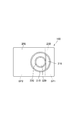
- FIG. 4 is a top view of the reserve tank with the cap removed.
- FIG. 5 is a view showing a cross section taken along line VV of FIG. 2, and is a view showing a structure of a switching mechanism provided in the reserve tank device.
- FIG. 6 is a diagram showing a state in which the plug of the switching mechanism has slid from the state shown in FIG. FIG.
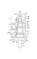
- FIG. 7 is a diagram illustrating a structure of a switching mechanism provided in the reserve tank device according to the second embodiment.
- FIG. 8 is a diagram showing the shape of the annular member provided in the switching mechanism shown in FIG.
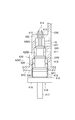
- FIG. 9 is a diagram illustrating a structure of a switching mechanism provided in the reserve tank device according to the third embodiment.
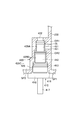
- FIG. 10 is a diagram illustrating a structure of a switching mechanism provided in the reserve tank device according to the fourth embodiment.
- FIG. 11 is a diagram illustrating a structure of a switching mechanism provided in the reserve tank device according to the fifth embodiment.
- the reserve tank device 100 is a device provided in a cooling system CS mounted on a vehicle (not shown). Prior to the description of the reserve tank device 100, first, the configuration of the cooling system CS will be described with reference to FIG.
- the cooling system CS is a system for cooling each part of the vehicle by circulating cooling water.
- the engine EG and the accessories EQ are cooling targets of the cooling system CS.
- the engine EG is a device that generates driving force for a vehicle by burning fuel.
- the auxiliary equipment EQ is, for example, an intercooler for cooling the air that has been compressed by the supercharger and has become high temperature before reaching the engine EG.
- the cooling system CS supplies cooling water to each of the engine EG and the accessories EQ to cool them and keep them at an appropriate temperature.
- the auxiliary equipment EQ may be a device other than the intercooler.
- the cooling system CS has a first cooling path 10 and a second cooling path 20.
- the first cooling path 10 is a path through which cooling water for cooling the auxiliary equipment EQ circulates.
- the second cooling path 20 is a path through which cooling water for cooling the engine EG circulates.
- the first cooling path 10 will be described.
- the first cooling path 10 includes a pipe 15, a pipe 16, a first water pump 13, and a first radiator 11. Further, as described later, a first space SP1 and a second space SP2 are formed in the tank section 200 of the reserve tank device 100. Of these, the first space SP1 is also included in the first cooling path 10.
- the pipe 15 is a pipe provided to guide the cooling water discharged from the auxiliary equipment EQ to the first space SP1.
- the pipe 16 is a pipe provided to guide the cooling water discharged from the first space SP1 to the auxiliary equipment EQ.
- the first water pump 13 is a pump for sending out cooling water so as to circulate through the first cooling path 10.
- the first water pump 13 is provided at a position in the middle of the pipe 15.
- the cooling water sent out by the first water pump 13 sequentially circulates through the first radiator 11, the first space SP1, the accessories EQ, and then returns to the first water pump 13.
- the first radiator 11 is a heat exchanger for exchanging heat between cooling water and air.
- the first radiator 11 is provided in the middle of the pipe 15 at a position downstream of the first water pump 13. Air is blown into the first radiator 11 by a blower fan 12 provided in the vicinity thereof. In the first radiator 11, heat exchange is performed between the air and the cooling water passing through the pipe 15.
- the cooling water that has become high in temperature when passing through the accessories EQ is cooled by air when passing through the first radiator 11, and lowers its temperature.
- the cooling water is supplied again to the auxiliary equipment EQ via the first space SP1, and is used for cooling the auxiliary equipment EQ.
- the cooling water circulating through the first cooling path 10 as described above corresponds to the “first fluid” in the present embodiment.
- the second cooling path 20 will be described.
- the second cooling path 20 includes a pipe 25, a pipe 26, a second water pump 23, and a second radiator 21.
- the second space SP2 of the reserve tank device 100 described above is also included in the second cooling path 20.
- the pipe 25 is a pipe provided to guide the cooling water discharged from the engine EG to the second space SP2.
- the pipe 26 is a pipe provided to guide the cooling water discharged from the second space SP2 to the engine EG.
- the second water pump 23 is a pump for sending out cooling water so as to circulate in the second cooling path 20.
- the second water pump 23 is provided at a position in the middle of the pipe 26.
- the cooling water sent out by the second water pump 23 basically circulates in a path passing through the engine EG and the second radiator 21.
- a pipe 27 is provided separately from the pipes 25 and 26. One end of the pipe 27 is connected to a position in the middle of the pipe 25. The other end of the pipe 27 is connected to a portion of the pipe 26 on the upstream side of the second water pump 23, that is, on the side opposite to the engine EG.
- the second radiator 21 is provided on the pipe 27.
- the second radiator 21 is a heat exchanger for exchanging heat between cooling water and air. Air is blown into the second radiator 21 by a blower fan 22 provided near the second radiator 21. In the second radiator 21, heat exchange is performed between the air and the cooling water passing through the pipe 27.
- the cooling water that has become high in temperature when passing through the engine EG is cooled by air when passing through the second radiator 21 and lowers its temperature.
- the cooling water is supplied to the engine EG again to be used for cooling the engine EG.
- the cooling water circulating in the second cooling path 20 as described above corresponds to the “second fluid” in the present embodiment.
- the same fluid is used as the first fluid and the second fluid. As such a fluid, for example, LLC can be used.
- a switching valve (not shown) is provided in a portion of the pipe 25 to which the pipe 27 is connected.
- the switching valve switches between a state in which the cooling water discharged from the engine EG is supplied to the second radiator 21 and a state in which the cooling water discharged from the engine EG is supplied to the second space SP2. .
- the cooling water circulates in a path passing through the engine EG and the second radiator 21.
- the cooling water circulates in a path passing through the engine EG and the second space SP2.
- the path through which the cooling water passes through the second space SP2 can be referred to as a bypass path for flowing the cooling water so as to bypass the second radiator 21.
- the configurations of the first cooling path 10 and the second cooling path 20 may be different from those described above.
- the second space SP2 is not located in the middle of the bypass path as described above, but is a position where the cooling water is in the middle of the path circulating through the engine EG and the second radiator 21.
- the second space SP2 may be arranged.
- the first space SP1 may be arranged at a position in the middle of the bypass path for flowing the cooling water so as to bypass the auxiliary equipment EQ.
- the reserve tank device 100 is provided for storing therein the cooling water circulating in the first cooling path 10 and the cooling water circulating in the second cooling path 20.
- the reserve tank device 100 includes a tank section 200, a first cylindrical section 210, a second cylindrical section 220, and a cap 300.
- the tank unit 200 is a part configured as a container in which the first space SP1 and the second space SP2 are formed.
- the first space SP1 is formed as a space for storing cooling water (first fluid) circulating in the first cooling path 10.
- the second space SP2 is formed as a space for storing cooling water (second fluid) circulating in the second cooling path 20.
- the first space SP1 and the second space SP2 are partitioned by a partition wall 230 provided inside the tank section 200.
- the partition wall 230 is a flat wall formed to extend from the lower end to the upper end in the internal space of the tank unit 200.
- the first space SP1 and the second space SP2 are formed so as to be adjacent to each other via the partition wall 230.
- the temperature and pressure of the cooling water circulating in the second cooling path 20 are higher than the temperature and pressure of the cooling water circulating in the first cooling path 10. For this reason, when the first fluid and the second fluid are circulating in the cooling system CS, the pressure of the cooling water (second fluid) in the second space SP2 is equal to the pressure of the cooling water (first fluid) in the first space SP1. Fluid).
- the tank part 200 is formed of a transparent resin, specifically, polypropylene. Therefore, the operation of supplying the cooling water to the tank unit 200 can be performed while visually checking the water level in the tank unit 200.
- the end of the pipe 15 and the end of the pipe 16 are connected to a portion of the tank 200 that partitions the first space SP1 from the external space.
- An end of the pipe 25 and an end of the pipe 26 are connected to a portion of the tank 200 that partitions the second space SP2 from the external space.
- a switching mechanism 400 is provided inside the tank section 200 along a lower portion of the partition wall 230. The function and configuration of the switching mechanism 400 will be described later.
- the first cylindrical portion 210 is a cylindrical portion formed so as to protrude further upward, that is, outward from the upper portion of the tank portion 200.
- the central axis of the first cylindrical portion 210 is along the vertical direction.
- the first cylindrical portion 210 is a portion that receives cooling water supplied from the outside at the time of manufacturing or maintenance of the cooling system CS. That is, the opening formed at the upper end of the first cylindrical portion 210 is a water inlet for supplying cooling water. Normally, as shown in FIG. 2, the upper end of the first cylindrical portion 210 is closed by the cap 300.
- the second cylindrical part 220 is a cylindrical part formed inside the first cylindrical part 210 so as to project from the tank part 200 in the same direction as the first cylindrical part 210.
- the central axis of the first cylindrical part 210 and the central axis of the second cylindrical part 220 match each other.
- the position of the upper end of the second cylindrical portion 220 is lower than the position of the upper end of the first cylindrical portion 210.
- the first cylindrical part 210 and the second cylindrical part 220 are both formed of the same resin as the tank part 200.
- the first cylindrical portion 210 and the second cylindrical portion 220 are formed as separate components from the tank portion 200, and then attached and fixed to the tank portion 200.
- an aspect in which the entire first cylindrical portion 210, the second cylindrical portion 220, and the tank portion 200 are integrally formed of resin may be employed.
- FIG. 3 shows a state in which the cap 300 is removed from the upper end of the first cylindrical portion 210.
- FIG. 4 shows a state in which the tank unit 200 with the cap 300 removed as described above is viewed from above.
- the space inside the first cylindrical portion 210 overlaps each of the first space SP1 and the second space SP2 in a top view.
- the space inside the second cylindrical portion 220 overlaps only with the second space SP2 when viewed from above, and does not overlap with the first space SP1.
- an opening 219 is formed in a portion of the tank portion 200 that is inside the first cylindrical portion 210 and overlaps the first cylindrical portion 210 in a top view.
- a portion inside the first cylindrical portion 210 and not overlapping the first cylindrical portion 210 in a top view is closed by a wall, specifically, an upper portion of the tank portion 200.
- the space formed inside the first cylindrical portion 210 and outside the second cylindrical portion 220 is connected to the first space SP1 via the opening 219, but is not connected to the second space SP2.
- the space formed inside the first cylindrical part 210 and outside the second cylindrical part 220 is for guiding a part of the cooling water supplied from the upper end part of the first cylindrical part 210 to the first space SP1. It is an introduction route. For this reason, the space is hereinafter also referred to as “first introduction path FP1”.
- An opening 229 is formed in the entire tank 200 inside the second cylindrical portion 220.
- the space formed inside the second cylindrical portion 220 is connected to the second space SP2 via the opening 229, but is not connected to the first space SP1.
- the space formed inside the second cylindrical portion 220 is an introduction path for guiding a part of the cooling water supplied from the upper end of the first cylindrical portion 210 to the second space SP2. For this reason, the space is hereinafter also referred to as “second introduction path FP2”.
- a male screw 211 is formed on the outer peripheral surface of the first cylindrical portion 210 near the upper end.
- the male screw 211 is for fixing the cap 300 to the first cylindrical portion 210 by screwing with a female screw 311 formed on the cap 300 described later.
- the cap 300 is a lid that is attached to the tip of the first cylindrical portion 210 to prevent the cooling water stored in the tank portion 200 from leaking outside.
- the cap 300 includes a flat plate portion 301, a first cylindrical portion 310, a second cylindrical portion 320, an urging portion 340, and a pressure valve 350.
- the flat plate portion 301 is a portion formed as a circular flat plate.
- the flat plate portion 301 is disposed so as to cover the first cylindrical portion 210 from above with its normal direction along the center axis of the first cylindrical portion 210.
- the center of the flat plate portion 301 is on the center axis of the first cylindrical portion 210.
- the diameter of the flat plate portion 301 is larger than the outer diameter of the first cylindrical portion 210.
- the flat plate portion 301 is formed integrally with a first cylindrical portion 310 and a second cylindrical portion 320, which will be described below, from resin. Instead of such a mode, a mode in which the flat plate portion 301 and the like are formed of metal instead of resin may be used.
- the first cylindrical portion 310 is a cylindrical portion formed to extend from the outer peripheral end of the flat plate portion 301 toward the lower side, that is, toward the tank 200 side.
- the female screw 311 described above is formed on the inner peripheral surface of the first cylindrical portion 310. As shown in FIG. 2, when the cap 300 is attached to the first cylindrical portion 210, the central axis of the first cylindrical portion 310 coincides with the central axis of the first cylindrical portion 210.
- the second cylindrical portion 320 is a cylindrical portion formed to extend from a portion of the flat plate portion 301 inside the first cylindrical portion 310 in the same direction as the first cylindrical portion 310, that is, downward. is there.
- the central axis of the second cylindrical portion 320 matches the central axis of the first cylindrical portion 310.
- the length of the second cylindrical portion 320 along the vertical direction is shorter than the length of the first cylindrical portion 310 along the same direction.
- the inner and outer diameters of the second cylindrical portion 320 match the inner and outer diameters of the first cylindrical portion 210, respectively.
- a seal member 330 is attached to the tip of the second cylindrical portion 320.
- the seal member 330 is formed by processing flat rubber into an annular shape, and is attached so as to cover the entire distal end surface of the second cylindrical portion 320.
- the rubber for example, natural rubber or ethylene propylene rubber can be used.
- the seal member 330 is sandwiched between the second cylindrical portion 320 and the first cylindrical portion 210 so that the seal member 330 Is pressed against the distal end surface of the first cylindrical portion 210. This prevents the cooling water stored in the first space SP1 from leaking out of the tank 200 through the first introduction path FP1.
- the urging portion 340 is for urging the pressurizing valve 350 described below toward the second cylindrical portion 220, and is specifically a coil spring.
- One end of the urging portion 340 is connected to the lower surface of the flat plate portion 301 in a state where the direction of expansion and contraction is set along the central axis of the first cylindrical portion 310.
- the other end of the urging portion 340 is connected to the upper surface of the pressurizing valve 350.
- Pressure valve 350 is a circular metal plate, and is formed in a substantially flat shape.
- the pressurizing valve 350 is connected to the lower end of the urging portion 340 with its normal direction along the center axis of the first cylindrical portion 310.
- the diameter of the pressure valve 350 is larger than the outer diameter of the second cylindrical part 220 and smaller than the inner diameter of the first cylindrical part 210.
- a seal member 360 is attached to the lower surface of the pressurizing valve 350, that is, a portion facing the upper end surface of the second cylindrical portion 220.
- the seal member 360 is formed by processing flat rubber into an annular shape.
- the seal member 360 is attached so as to cover the entire lower surface of the pressurizing valve 350 facing the distal end surface of the second cylindrical portion 220.
- the rubber for example, natural rubber or ethylene propylene rubber can be used.
- the length of the urging portion 340 along the vertical direction is shorter than the natural length of the urging portion 340. . Therefore, the pressurizing valve 350 is urged downward by the urging portion 340, and the seal member 360 is pressed against the distal end surface of the second cylindrical portion 220. As a result, the first introduction path FP1 connected to the first space SP1 and the second introduction path FP2 connected to the second space SP2 are completely separated by the pressure valve 350. This prevents the cooling water stored in the second space SP2 from leaking outside through the second introduction path FP2, that is, to the first introduction path FP1.
- each of the first introduction path FP1 and the second introduction path FP2 is open to the outside.
- an attachment for water supply is connected to the tip of the first cylindrical portion 210, and cooling water is supplied from the attachment to the first cylindrical portion 210.
- a part of the cooling water is supplied to the first space SP1 through the first introduction path FP1, and the rest is supplied to the second space SP2 through the second introduction path FP2.
- the cooling water is simultaneously supplied to the first space SP1 and the second space SP2 from one water inlet, that is, the tip of the first cylindrical portion 210. can do. That is, the supply of the cooling water to the plurality of spaces can be completed in one step.
- the cap 300 for preventing the leakage of the cooling water to the outside is not provided for each of the first space SP1 and the second space SP2, but is provided only by one cap 300. Leakage of cooling water from each space is prevented. Therefore, the number of caps 300 can be reduced and the number of parts can be reduced as compared with the conventional configuration.
- the cap 300 is attached to the tip of the first cylindrical portion 210.
- the male screw 211 and the female screw 311 are screwed together. 300 gradually moves downward.
- the seal member 360 of the pressurizing valve 350 contacts the distal end surface of the second cylindrical portion 220.
- the length of the urging portion 340 gradually decreases, and the seal member 360 is pressed against the distal end surface of the second cylindrical portion 220. The operation of rotating and tightening the cap 300 is performed until the seal member 330 is sufficiently pressed against the tip of the first cylindrical portion 210.
- the pressurizing valve 350 When the pressure inside the first space SP1 becomes too high due to, for example, the temperature of the cooling water circulating in the first cooling path 10 becoming too high, the pressurizing valve 350 is pushed upward by the pressure, The first space SP1 and the second space SP2 are in a state where they are communicated with each other. Thereby, the pressure in the first space SP1 decreases.
- the pressurizing valve 350 urged by the urging unit 340 is configured to be opened according to the pressure increase in the first space SP1. I have. This can prevent a situation in which a part of the cooling system CS is damaged by the pressure of the cooling water.
- the first space SP1 may be filled with the cooling water first. In this case, it is necessary to additionally supply the cooling water only to the second space SP2, so that the number of steps for supplying the cooling water eventually increases.
- a switching mechanism 400 is provided in the tank section 200 of the reserve tank device 100 according to the present embodiment as a mechanism for making this possible.
- the switching mechanism 400 switches the state in which the first space SP1 and the second space SP2 are communicated with each other and the state in which the first space SP1 and the second space SP2 are not communicated with each other from the outside of the tank unit 200. Is to be switched by the above operation.
- FIG. 5 shows a VV cross section of FIG.
- the switching mechanism 400 has a receiving part 420 and a plug 410.
- FIG. 5 shows a cross section of the receiving portion 420 provided in the switching mechanism 400, but the plug 410 provided in the switching mechanism 400 is not a cross section but an appearance.
- the receiving portion 420 is a cylindrical portion that receives the plug 410 described below inside.
- the receiving part 420 supports the plug 410 so as to be slidable in a predetermined direction.
- the “predetermined direction” is a longitudinal direction of the plug 410 and a direction along the surface of the partition wall 230 on the first space SP1 side.
- the predetermined direction is a vertical direction in FIG. 5 and a depth direction in FIG. 2 and FIG.
- the direction toward the upper side of FIG. 5 along the above-described predetermined direction may be referred to as the “rear side”, and the direction toward the lower side of FIG. Things may be described as "outside"
- the receiving section 420 is formed so as to be integrated with the tank section 200.
- the receiving portion 420 is formed by protruding a part of the partition wall 230 toward the second space SP2 in a lower portion of the first space SP1.
- the receiving portion 420 is formed to extend from the lower end of the second space SP2 in FIG. 5 to a position substantially at the center of the second space SP2 along the partition wall 230. Note that the “lower end in FIG. 5” in the above refers to the end on the near side of the paper in FIGS. 2 and 3.
- a space for receiving the plug 410 is formed inside the receiving portion 420.
- the space is open to the outside of the tank 200 at the lower end in FIG.
- the receiving section 420 is further formed with a first communication path 421 and a second communication path 422.
- the first communication passage 421 is a through hole formed to penetrate a portion of the partition wall 230 where the receiving portion 420 is formed along the normal direction of the partition wall 230.
- the first communication path 421 is formed at a position near the end on the back side along the above-described predetermined direction in the receiving section 420. The space inside the receiving part 420 and the first space SP1 are communicated by the first communication path 421.
- the first communication path 421 allows communication between the internal space IS of the receiving part 420 and the first space SP1.
- the second communication path 422 is a through-hole formed so as to penetrate the end of the receiving part 420 on the far side along the above-described predetermined direction along the predetermined direction.
- the space inside the receiving part 420, specifically, the above-mentioned internal space IS and the second space SP2 are communicated by the second communication passage 422. If the plug 410 described below does not exist, the first space SP1 and the second space SP2 are connected to each other via the internal space IS.
- the plug 410 is a member that slides along the above-described predetermined direction. Most of the plug 410 is housed inside the receiving section 420, and is supported by the receiving section 420 in a slidable manner.
- FIG. 5 shows a state in which the plug 410 is located at a position that is the innermost side (upper side in FIGS. 5 and 6) of the movable range along a predetermined direction.
- FIG. 6 shows a state in which the plug 410 is located at the outermost position (the lower side in FIGS. 5 and 6) along the predetermined direction in the movable range.
- the plug 410 has a first part 411, a second part 412, a third part 413, a flange 418, and a grip part 417.
- the first portion 411 is a substantially columnar portion.
- the first portion 411 is arranged with its central axis along the above-described predetermined direction. In the state shown in FIG. 5, the first portion 411 is arranged substantially entirely in the internal space IS.
- the inner diameter of the portion that accommodates the first portion 411 in FIG. 5 is slightly larger than the outer diameter of the first portion 411.
- a portion of the receiving portion 420 whose inner diameter is slightly larger than the outer diameter of the first portion 411 as described above is also referred to as a “first storage portion 429A” below.
- the first portion 411 is provided with an O-ring OR1.
- the O-ring OR1 is provided on the outer peripheral surface of the first portion 411 at a position between the first communication passage 421 and the second communication passage 422 in FIG.
- the O-ring OR1 is in contact with the inner peripheral surface of the first housing portion 429A over the entire circumference. Therefore, when the plug 410 is at the position shown in FIG. 5, the first communication path 421 and the second communication path 422 are separated by the O-ring OR1.
- the O-ring OR1 separating the first communication path 421 and the second communication path 422 is for separating the first communication path 421 and the second communication path 422 in this manner, and is the present embodiment. Corresponds to the “first seal portion”.
- the second portion 412 is a substantially columnar portion similar to the first portion 411.
- the central axis of the second part 412 coincides with the central axis of the first part 411.
- the outer diameter of the second portion 412 is larger than the outer diameter of the first portion 411.
- the inner diameter of a portion of the receiving portion 420 that accommodates the second portion 412 in FIG. 5 is slightly larger than the outer diameter of the second portion 412.
- a portion of the receiving portion 420 whose inner diameter is slightly larger than the outer diameter of the second portion 412 as described above is also referred to as a “second storage portion 429B” below.
- the second portion 412 is provided with an O-ring OR2.
- the O-ring OR2 is provided at a position closer to the first portion 411 on the outer peripheral surface of the second portion 412.
- the O-ring OR2 is in contact with the inner peripheral surface of the second housing portion 429B over the entire circumference.
- the second portion 412 is disposed at a position that is entirely on the grip portion 417 side of the first communication path 421, that is, on a side opposite to the first portion 411. Therefore, when the plug 410 is at the position shown in FIG. 5, the space outside the tank 200 and the internal space IS are separated by the O-ring OR2. As a result, leakage of the cooling water from the internal space IS to the outside is prevented.
- the O-ring OR2 that separates the space outside the tank 200 from the internal space IS is used to separate the space outside the tank 200 from the internal space IS. Corresponds to the “second seal portion”.
- the O-ring OR2 can be said to divide the space inside the receiving section 420 into the internal space IS and other spaces.
- the space behind the O-ring OR2 that is, the space on the side of the second communication passage 422 is defined as "internal space IS".
- the third portion 413 is a substantially columnar portion similar to the second portion 412.
- the central axis of the third part 413 coincides with the central axis of the second part 412.
- the outer diameter of the third portion 413 is larger than the outer diameter of the second portion 412.
- the inside diameter of the portion that accommodates the third portion 413 in FIG. 5 is slightly larger than the outside diameter of the third portion 413.
- the portion of the receiving portion 420 whose inner diameter is slightly larger than the outer diameter of the third portion 413 as described above is hereinafter also referred to as a “third accommodation portion 429C”.
- the third portion 413 extends in the state of FIG. 5 along the above-described predetermined direction to a position on the outer surface of the tank unit 200.
- a male screw 416 is formed on the outer peripheral surface of the third portion 413.
- a female screw 426 is formed on a portion of the inner peripheral surface of the third housing portion 429C that faces the male screw 416 in FIG. In the state of FIG. 5, the male screw 416 is screwed with the female screw 426, whereby the plug 410 is fixed at the position of FIG.
- the flange 418 is a disk-shaped portion formed at a position adjacent to the third portion 413 along the above-described predetermined direction, specifically, at a position outside the third portion 413.
- the central axis of the flange 418 coincides with the central axis of the third portion 413.
- the outer diameter of the flange 418 is larger than the outer diameter of the third portion 413. In the state shown in FIG. 5, a portion of the flange 418 on the outer peripheral side of the third portion 413 is in contact with the outer surface of the tank 200.
- the grip portion 417 is a columnar portion formed to protrude outward from the flange 418.
- the central axis of the grip 417 matches the central axis of the flange 418.
- the grip portion 417 is a portion that is gripped by the user when the position of the plug 410 is changed by sliding.
- a pair of hooks 414 are provided on the distal end face on the far side of the first portion 411.
- the hook 414 is a rod-shaped portion formed to extend from the distal end surface of the first portion 411 to the back side along the above-described predetermined direction.
- Each hook 414 is formed to extend to the second space SP2 through the second communication path 422.
- each hook 414 On each side surface of each hook 414, a claw-shaped protrusion 415 is formed so as to protrude toward the side.
- the direction in which the protrusion 415 projects from one hook 414 is the direction opposite to the other hook 414.
- the distance W2 between the tips of the respective protrusions 415 is larger than the inner diameter W1 of the second communication path 422.
- each projection 415 is formed in a tapered shape such that the width between the projections 415 decreases toward the tip end. Therefore, when the projection 415 is passed from the internal space IS side to the second communication path 422, the respective hooks 414 are bent, so that the projection 415 can be passed to the second space SP2 side. On the other hand, when the plug 410 is pulled out from the state shown in FIG. 410 cannot be withdrawn. As described above, the hook 414 is provided to define the operation range of the plug 410.
- the distance from the edge of the second communication passage 422 in the receiving portion 420 to the protrusion 415 of the hook 414 is indicated as “L1”.
- the distance from the O-ring OR1 to the outermost end of the first communication path 421 along the above-described predetermined direction is indicated as “L3”.
- the distance from the O-ring OR2 to the outermost end of the second housing portion 429B along the above-described predetermined direction is indicated as “L2”.
- the plug 410 is in the state shown in FIG. In this state, the first communication passage 421 and the second communication passage 422 are separated by the O-ring OR1 (first seal portion), and the space outside the tank portion 200 and the internal space IS are separated. The space is separated by an O-ring OR2 (second seal portion).
- the position of the plug 410 in such a state is also referred to as an “initial position”.
- the male screw 416 is screwed with the female screw 426, and the plug 410 is fixed thereby.
- the male screw 416 formed on the outer peripheral surface of the third portion 413 of the plug 410 corresponds to a “fixing mechanism” for fixing the plug 410 at the initial position.
- the user slides the plug 410 outward in advance. Specifically, the user grips the grip portion 417 of the plug 410 and rotates the male screw 416 and the female screw 426 in a direction in which the screw engagement is loosened. As a result, the plug 410 gradually slides outward. After the screwing of the male screw 416 and the female screw 426 is completely released, the user slides the plug 410 by further pulling the grip portion 417 of the plug 410 outward. Eventually, the plug 410 slides to the outermost position in its movable range, and is in the state shown in FIG.
- the O-ring OR1 has moved to a position outside the first communication path 421, that is, a position opposite to the second communication path 422.
- the first communication path 421 and the second communication path 422 are not separated by the O-ring OR1, and are in communication with each other via the internal space IS.
- the first space SP1 and the second space SP2 communicate with each other.
- limit position L2 described above corresponds to the distance from the initial position to the limit position.
- the distance corresponds to the “second distance” in the present embodiment.
- the protrusion 415 422 is configured to hit the edge portion. Thereby, the sliding of the plug 410 beyond the limit position is suppressed, and as a result, the leakage of the cooling water to the outside is prevented.
- the projection 415 which is a claw-shaped portion formed on the plug 410, corresponds to a "suppression mechanism" for suppressing the slide of the plug 410 beyond the limit position.
- L L1 described above corresponds to the distance from the initial position to the position where the sliding of the plug 410 is suppressed by the above-described suppressing mechanism.
- the distance corresponds to the “first distance” in the present embodiment.
- the plug 410 and the receiving portion 420 are set such that the first distance (L1) is smaller than the second distance (L2) so that the protrusion 415 can function as a suppressing mechanism as described above. It is configured.
- LL3 described above can be said to be the distance from the initial position to the position of the plug 410 at which the first communication path 421 and the second communication path 422 are in communication with each other.
- the distance corresponds to the “third distance” in the present embodiment.
- the plug 410 and the receiving section 420 are configured such that the first distance (L1) is larger than the third distance (L3). In such a configuration, the sliding of the plug 410 is not hindered by the suppression mechanism until the state where the first communication path 421 and the second communication path 422 are completely communicated with each other.
- the restraining mechanism may be a mechanism that directly suppresses the movement of the plug 410 in the predetermined direction as in the present embodiment, or may be an indirect mechanism that suppresses the movement of the plug 410 in the predetermined direction.
- the rotation range of the plug 410 for loosening the screw is limited to a predetermined range.
- a suppression mechanism may be configured as a mechanism that performs this. In this case, the suppression mechanism indirectly suppresses the slide of the plug 410 along the predetermined direction by suppressing the rotation of the plug 410.
- the second embodiment will be described mainly with reference to FIG.
- points different from the first embodiment will be mainly described, and description of points common to the first embodiment will be appropriately omitted.
- the present embodiment differs from the first embodiment in the configuration of the plug 410.
- the hook 414 is not provided on the first portion 411 of the plug 410, and the projection 419 is provided instead.
- the protrusion 419 is formed in a substantially columnar shape, and its central axis coincides with the central axis of the first portion 411.
- the protrusion 419 is formed so as to extend from the distal end surface of the first portion 411 to the back side in the above-described predetermined direction.
- a concave groove 419A along the circumferential direction is formed at a position near the distal end on the back side of the side surface of the protrusion 419.
- An annular member CR is attached to the groove 419A.
- the annular member CR is a flat plate-like member, and has an annular shape when viewed along a predetermined direction. As shown in FIG. 8, a part of the annular member CR is cut out so as to be attachable to the groove 419A, and the whole is a C-shaped member.
- the inner diameter d1 of the annular member CR is substantially equal to the outer diameter of the protrusion 419 at the groove 419A.
- the outer diameter W3 of the annular member CR is larger than the inner diameter W1 of the second communication passage 422. For this reason, when the plug 410 is pulled out from the initial position, the annular member CR hits the edge of the second communication passage 422 in the receiving portion 420, and the plug 410 cannot be pulled out further. That is, the annular member CR attached to the projection 419 of the plug 410 corresponds to the “suppression mechanism” in the present embodiment.
- the projection 419 is attached to the groove 419A after the projection 419 is passed through the second communication passage 422 from the internal space IS side.
- L1 corresponds to the “first distance” in the present embodiment. Also in the present embodiment, the first distance (L1) is smaller than the second distance (L2) and larger than the third distance (L3).
- a third embodiment will be described with reference to FIG.
- points different from the first embodiment will be mainly described, and description of points common to the first embodiment will be appropriately omitted.
- the present embodiment also differs from the first embodiment in the configuration of the plug 410.
- the hook 414 is not provided on the first portion 411 of the plug 410, and the projection 419 as in the second embodiment is not provided. That is, in the present embodiment, no suppression mechanism is provided.
- a fourth embodiment will be described with reference to FIG.
- points different from the first embodiment will be mainly described, and description of points common to the first embodiment will be appropriately omitted.
- This embodiment is different from the first embodiment in the configuration of the plug 410 and the receiving unit 420.
- a male screw 411A is formed on the outer peripheral surface of the first portion 411 of the plug 410.
- the position where the male screw 411A is formed is a position that is located further back than the first communication path 421 in the above-described predetermined direction when the plug 410 is at the initial position as shown in FIG.
- a female screw 427 is formed on the inner peripheral surface of the first housing portion 429A of the receiving portion 420.
- the position where the female screw 427 is formed is a position facing the male screw 411A of the plug 410 when the plug 410 is at the initial position as shown in FIG.
- the male screw 411A and the female screw 427 are formed as so-called “seal screws”.
- the male screw 411A is screwed into the female screw 427, and the space between them is kept watertight. That is, the first communication path 421 and the second communication path 422 are separated from each other.
- the male screw 411A formed on the outer peripheral surface of the plug 410 is for separating the first communication path 421 and the second communication path 422 in this manner, and is referred to as a “first seal portion” in the present embodiment. Corresponds to.
- the male screw 416 is not formed on the outer peripheral surface of the third portion 413, and the female screw 426 is not formed on the inner peripheral surface of the third housing portion 429C.
- the fixing of the plug 410 in the initial position is performed by the male screw 411A in the present embodiment.
- the male screw 411A also corresponds to the “fixing mechanism” in the present embodiment. Even in the above-described mode, the same effects as those described in the first embodiment can be obtained.
- a fifth embodiment will be described with reference to FIG.
- points different from the first embodiment will be mainly described, and description of points common to the first embodiment will be appropriately omitted.
- This embodiment also differs from the first embodiment in the configuration of the plug 410 and the receiving section 420.
- the male screw 416 is not formed on the outer peripheral surface of the third portion 413, and the female screw 426 is not formed on the inner peripheral surface of the third housing portion 429C.
- the protrusion 413A is provided on the outer peripheral surface of the third portion 413 of the plug 410.
- a plurality of protrusions 413A are provided, and these are arranged so as to be arranged along the circumferential direction of the third portion 413.
- Each protrusion 413A can move along the radial direction of the third portion 413.
- Each projection 413A is biased radially outward of the third portion 413 by a biasing mechanism (not shown) provided inside the third portion 413.
- the tip of each protrusion 413A is machined to be spherical.
- a concave portion 428 is formed on the inner peripheral surface of the third housing portion 429C along the circumferential direction.
- the position where the concave portion 428 is formed is a position facing the protruding portion 413A when the plug 410 is at the initial position as shown in FIG.
- each protruding portion 413A protruding from the outer peripheral surface of the third portion 413 is accommodated in the concave portion 428 formed on the inner peripheral surface of the third accommodating portion 429C. I have.
- the position of the plug 410 is fixed at the initial position. That is, the protruding portion 413A provided so as to protrude outward from the outer peripheral surface of the plug 410 corresponds to the “fixing mechanism” in the present embodiment.
- each protruding portion 413A is retracted inward in the radial direction by the force received from the concave portion 428, so that the plug 410 becomes movable.
Landscapes
- Engineering & Computer Science (AREA)
- Chemical & Material Sciences (AREA)
- Combustion & Propulsion (AREA)
- Mechanical Engineering (AREA)
- General Engineering & Computer Science (AREA)
- Cooling, Air Intake And Gas Exhaust, And Fuel Tank Arrangements In Propulsion Units (AREA)
Abstract
リザーブタンク装置(100)は、第1空間(SP1)と第2空間(SP2)とが互いに隣り合うように形成されているタンク部(200)と、前記タンク部から外側に突出するように形成された第1円筒部(210)と、前記第1円筒部の内側において、前記タンク部から前記第1円筒部と同じ方向に突出するように形成された第2円筒部(220)と、前記第1円筒部の先端に取り付けられるキャップ(300)と、を備える。前記第1円筒部の内側且つ第2円筒部の外側に形成された空間である第1導入路(FP1)は、前記第1空間に繋がっている。前記第2円筒部の内側に形成された空間である第2導入路(FP2)は、前記第2空間に繋がっている。前記キャップが前記第1円筒部の先端に取り付けられた状態においては、前記第1導入路と前記第2導入路との間が前記キャップによって互いに隔てられた状態となる。
Description
本出願は、2018年7月6日に出願された日本国特許出願2018-128956号に基づくものであって、その優先権の利益を主張するものであり、その特許出願の全ての内容が、参照により本明細書に組み込まれる。
本開示は、冷却システムに設けられるリザーブタンク装置に関する。
車両には、循環する冷却水によって車両の各部を冷却するための冷却システムが設けられる。冷却システムによって冷却される対象としては、例えばエンジンや、インタークーラ等の補機類が挙げられる。
エンジンと補機類のそれぞれの発熱量は互いに異なっており、保たれるべき温度の範囲も互いに異なっている。このため、冷却システムでは、冷却水の循環する経路を一つではなく複数備えるのが一般的となっている。例えば、エンジンに供給される冷却水の循環経路と、補機類に供給される冷却水の循環経路とを、互いに独立した経路として設けておけば、エンジン及び補機類のそれぞれを適温に保つことが可能となる。
ところで、冷却システムには、循環する冷却水の一部を貯留するためのリザーブタンク装置が設けられる。何らかの原因で冷却水が減少した際には、リザーブタンク装置から冷却水が補われる。これにより、冷却水の減少に伴う冷却性能の低下が防止される。また、リザーブタンク装置には、製造時やメンテナンス時において外部から冷却水を供給するための注水口が形成されることが多い。
下記特許文献1に記載された冷却システムでは、車載のエンジンを冷却するためのエンジン冷却回路と、車両の補機部品を冷却するための補機冷却用の低水温回路とが、それぞれ独立に設けられている。また、上記冷却システムでは、単一の密閉式リザーブタンクの内側が、仕切板によって二つの空間に分かれている。一方の空間には、エンジン冷却回路を循環する冷却水が貯留されており、他方の空間には、低水温回路を循環する冷却水が貯留されている。
このように、上記冷却システムでは、二つの循環経路のそれぞれに個別のリザーブタンク装置を設けるのではなく、単一のリザーブタンク装置を二つの循環経路で共有した構成となっている。リザーブタンク装置の内部空間は仕切板によって分離されているので、エンジン冷却回路を循環する高温の冷却水と、低水温回路を循環する低温の冷却水とが、リザーブタンクを通る際に混合されてしまうことは無い。
上記特許文献に記載された冷却システムでは、リザーブタンク装置の内側に冷却水を供給するための注水口が、リザーブタンク装置の上部に二つ設けられている。このため、製造時やメンテナンス時においては、エンジン冷却回路のための冷却水が一方の注水口から供給され、低水温回路のための冷却水が他方の注水口から供給されることとなる。しかしながら、冷却水の供給をこのように複数回に分けて行うと、工程の増加にともないコストが上昇してしまう。また、上記構成のリザーブタンク装置では、注水口を塞ぐためのキャップが複数必要となるので、部品点数が増加するという問題も生じる。
本発明者らは、上記問題を解決するために、リザーブタンク装置の内部空間を複数の空間に分けた上で、一つの注水口からそれぞれの空間へと冷却水を供給し得る構成について検討を進めている。しかしながら、二つの注水口を単純に一つにまとめただけでは、二つの内部空間が、注水口を塞ぐキャップの近傍において互いに連通してしまうこととなる。このような構成においては、例えば高温側の空間で生じた水蒸気が、低温側の空気に流入して凝縮する。その結果、高温側における冷却水の圧力が十分に上昇せず、沸点が低下してしまうという問題が生じる。
本開示は、一つの注水口から、第1空間及び第2空間のそれぞれに冷却水を供給し得る構成としながらも、第1空間と第2空間とを互いに隔てられた状態とすることのできるリザーブタンク装置、を提供することを目的とする。
本開示に係るリザーブタンク装置は、冷却システムに設けられるリザーブタンク装置であって、第1流体を貯留するための空間である第1空間と、第2流体を貯留するための空間である第2空間とが、隔壁を介して互いに隣り合うように形成されているタンク部と、タンク部から外側に突出するように形成された円筒形状の部分である第1円筒部と、第1円筒部の内側において、タンク部から第1円筒部と同じ方向に突出するように形成された円筒形状の部分である第2円筒部と、第1円筒部の先端に取り付けられるキャップと、を備える。第1円筒部の内側且つ第2円筒部の外側に形成された空間である第1導入路は、第1空間に繋がっている。第2円筒部の内側に形成された空間である第2導入路は、第2空間に繋がっている。キャップが第1円筒部の先端に取り付けられた状態においては、第1導入路と第2導入路との間がキャップによって互いに隔てられた状態となる。
このような構成のリザーブタンク装置では、第1円筒部の先端が、製造時等において冷却水を供給するための注水口として用いられる。第1円筒部から供給された冷却水の一部は、第1円筒部と第2円筒部との間に形成された第1導入路を通って第1空間に流入する。また、第1円筒部から供給された冷却水の他部は、第2円筒部の内側に形成された第2導入路を通って第2空間に流入する。このように、第1空間及び第2空間のそれぞれに冷却水を同時に供給することができるので、冷却水の供給を1つの工程で完了させることができる。
上記リザーブタンク装置では、キャップが第1円筒部の先端に取り付けられた状態においては、第1導入路と第2導入路との間がキャップによって互いに隔てられた状態となる。このため、冷却システムによる各部の冷却が行われているときには、第1空間と第2空間とが互いに隔てられた状態となる。第1空間から供給される冷却水の循環する経路と、第2空間から供給される冷却水の循環する経路と、が互いに分離された状態となるので、それぞれの経路を循環する冷却水が互いに混合されてしまうことが無い。このため、例えばエンジンに供給される冷却水の圧力を十分に上昇させ、当該冷却水の沸点を上昇させることが可能となる。
本開示によれば、一つの注水口から、第1空間及び第2空間のそれぞれに冷却水を注水し得る構成としながらも、第1空間と第2空間とが互いに隔てられた状態とすることのできるリザーブタンク装置、が提供される。
以下、添付図面を参照しながら本実施形態について説明する。説明の理解を容易にするため、各図面において同一の構成要素に対しては可能な限り同一の符号を付して、重複する説明は省略する。
第1実施形態について説明する。本実施形態に係るリザーブタンク装置100は、不図示の車両に搭載される冷却システムCSに設けられる装置である。リザーブタンク装置100の説明に先立ち、先ず冷却システムCSの構成について図1を参照しながら説明する。
冷却システムCSは、循環する冷却水によって車両の各部を冷却するためのシステムである。図1に示される例では、エンジンEGと補機類EQとが、冷却システムCSの冷却対象となっている。エンジンEGは、燃料の燃焼によって車両の駆動力を生じさせる装置である。補機類EQは、例えば、過給機によって圧縮され高温となった空気を、エンジンEGへの到達前に冷却しておくためのインタークーラである。冷却システムCSは、エンジンEG及び補機類EQのそれぞれに冷却水を供給することにより、これらを冷却し適温に保つものである。尚、補機類EQはインタークーラ以外の装置であってもよい。
冷却システムCSは、第1冷却経路10と、第2冷却経路20とを有している。第1冷却経路10は、補機類EQを冷却するための冷却水が循環する経路である。第2冷却経路20は、エンジンEGを冷却するための冷却水が循環する経路である。
第1冷却経路10について説明する。第1冷却経路10には、配管15と、配管16と、第1ウォーターポンプ13と、第1ラジエータ11と、が含まれている。また、後に説明するように、リザーブタンク装置100のタンク部200には第1空間SP1と第2空間SP2とが形成されている。これらのうち第1空間SP1も上記の第1冷却経路10に含まれている。
配管15は、補機類EQから排出された冷却水を第1空間SP1に導くように設けられた配管である。配管16は、第1空間SP1から排出された冷却水を補機類EQに導くように設けられた配管である。
第1ウォーターポンプ13は、第1冷却経路10を循環するように冷却水を送り出すためのポンプである。第1ウォーターポンプ13は配管15の途中となる位置に設けられている。第1ウォーターポンプ13によって送り出された冷却水は、第1ラジエータ11、第1空間SP1、補機類EQを順に通った後、第1ウォーターポンプ13に戻る経路で循環する。
第1ラジエータ11は、冷却水と空気との間で熱交換を行うための熱交換器である。第1ラジエータ11は、配管15の途中であって、第1ウォーターポンプ13よりも下流側となる位置に設けられている。第1ラジエータ11には、その近傍に設けられた送風ファン12によって空気が送り込まれる。第1ラジエータ11では、当該空気と、配管15を通る冷却水との間で熱交換が行われる。補機類EQを通る際に高温となった冷却水は、第1ラジエータ11を通る際において空気によって冷却され、その温度を低下させる。当該冷却水は、第1空間SP1を経て再び補機類EQに供給され、補機類EQの冷却に供される。第1冷却経路10を上記のように循環する冷却水は、本実施形態における「第1流体」に該当する。
第2冷却経路20について説明する。第2冷却経路20には、配管25と、配管26と、第2ウォーターポンプ23と、第2ラジエータ21と、が含まれている。また、先に述べたリザーブタンク装置100の第2空間SP2も、上記の第2冷却経路20に含まれている。
配管25は、エンジンEGから排出された冷却水を第2空間SP2に導くように設けられた配管である。配管26は、第2空間SP2から排出された冷却水をエンジンEGに導くように設けられた配管である。
第2ウォーターポンプ23は、第2冷却経路20を循環するように冷却水を送り出すためのポンプである。第2ウォーターポンプ23は配管26の途中となる位置に設けられている。第2ウォーターポンプ23によって送り出された冷却水は、基本的にはエンジンEG及び第2ラジエータ21を通る経路で循環する。
本実施形態の第2冷却経路20には、配管25及び配管26とは別に配管27が設けられている。配管27の一端は、配管25の途中となる位置に接続されている。配管27の他端は、配管26のうち、第2ウォーターポンプ23よりも上流側、すなわちエンジンEGとは反対側の部分に接続されている。第2ラジエータ21はこの配管27に設けられている。
第2ラジエータ21は、冷却水と空気との間で熱交換を行うための熱交換器である。第2ラジエータ21には、その近傍に設けられた送風ファン22によって空気が送り込まれる。第2ラジエータ21では、当該空気と、配管27を通る冷却水との間で熱交換が行われる。エンジンEGを通る際に高温となった冷却水は、第2ラジエータ21を通る際において空気によって冷却され、その温度を低下させる。当該冷却水は再びエンジンEGに供給され、エンジンEGの冷却に供される。第2冷却経路20を上記のように循環する冷却水は、本実施形態における「第2流体」に該当する。尚、冷却システムCSでは、第1流体及び第2流体としていずれも同種の流体が用いられる。このような流体としては、例えばLLCを用いることができる。
車両の走行中においては、エンジンEGの温度は補機類EQの温度よりも高くなる。このため、第2冷却経路20を循環する冷却水の温度及び圧力は、第1冷却経路10を循環する冷却水の温度及び圧力に比べて高くなる。
配管25のうち配管27が接続されている部分には、不図示の切換弁が設けられている。当該切換弁によって、エンジンEGから排出された冷却水が第2ラジエータ21側に供給される状態と、エンジンEGから排出された冷却水が第2空間SP2側に供給される状態と、が切り換えられる。前者の状態においては、既に述べたように、冷却水はエンジンEG及び第2ラジエータ21を通る経路で循環する。後者の状態においては、冷却水はエンジンEG及び第2空間SP2を通る経路で循環する。このように冷却水が第2空間SP2を通る経路は、第2ラジエータ21を迂回するように冷却水を流すためのバイパス経路、ということができる。
尚、第1冷却経路10及び第2冷却経路20のそれぞれの構成は、上記とは異なるものであってもよい。例えば、第2冷却経路20において、第2空間SP2が上記のようなバイパス経路の途中に配置されているのではなく、冷却水がエンジンEG及び第2ラジエータ21を循環する経路の途中となる位置に、第2空間SP2が配置されている構成としてもよい。また、第1冷却経路10において、補機類EQを迂回するように冷却水を流すためのバイパス経路の途中となる位置に、第1空間SP1が配置されている構成としてもよい。
続いて図2を主に参照しながら、リザーブタンク装置100の構成について説明する。リザーブタンク装置100は、第1冷却経路10を循環する冷却水、及び第2冷却経路20を循環する冷却水のそれぞれを、内部に貯留するためのものとして設けられている。リザーブタンク装置100は、タンク部200と、第1円筒部210と、第2円筒部220と、キャップ300と、を備えている。
タンク部200は、第1空間SP1及び第2空間SP2が内部に形成された容器、として構成された部分である。先に述べたように、第1空間SP1は、第1冷却経路10を循環する冷却水(第1流体)を貯留するための空間として形成されている。また、第2空間SP2は、第2冷却経路20を循環する冷却水(第2流体)を貯留するための空間として形成されている。第1空間SP1と第2空間SP2との間は、タンク部200の内部に設けられた隔壁230によって区画されている。隔壁230は、タンク部200の内部空間における下端から上端まで伸びるように形成された平板状の壁である。タンク部200では、第1空間SP1と第2空間SP2とが、隔壁230を介して互いに隣り合うように形成されている。
先に述べたように、第2冷却経路20を循環する冷却水の温度及び圧力は、第1冷却経路10を循環する冷却水の温度及び圧力に比べて高くなる。このため、冷却システムCSを第1流体及び第2流体がそれぞれ循環しているときにおいては、第2空間SP2における冷却水(第2流体)の圧力は、第1空間SP1における冷却水(第1流体)の圧力よりも高くなる。
タンク部200は透明な樹脂、具体的にはポリプロピレンによって形成されている。このため、タンク部200に冷却水を供給する作業を、タンク部200内における水位を視認しながら行うことが可能となっている。
タンク部200のうち、第1空間SP1と外部空間との間を区画している部分には、配管15の端部及び配管16の端部がそれぞれ接続されている。タンク部200のうち、第2空間SP2と外部空間との間を区画している部分には、配管25の端部及び配管26の端部がそれぞれ接続されている。
タンク部200の内部には、隔壁230のうち下方側の部分に沿って切換機構400が設けられている。切換機構400の機能や構成については後に説明する。
第1円筒部210は、タンク部200のうち上方側の部分から、更に上方側、つまり外側に向けて突出するように形成された円筒形状の部分である。第1円筒部210の中心軸は鉛直方向に沿っている。第1円筒部210は、冷却システムCSの製造時やメンテナンス時において、外部から供給される冷却水を受け入れる部分となっている。つまり、第1円筒部210の上端部に形成された開口が、冷却水を供給するための注水口となっている。通常時においては、図2に示されるように、第1円筒部210の上端部がキャップ300で塞がれた状態となっている。
第2円筒部220は、第1円筒部210の内側において、タンク部200から第1円筒部210と同じ方向に突出するように形成された円筒形状の部分である。本実施形態では、第1円筒部210の中心軸と、第2円筒部220の中心軸とが互いに一致している。第2円筒部220の上端部の位置は、第1円筒部210の上端部の位置よりも低い位置となっている。
本実施形態では、第1円筒部210及び第2円筒部220は、いずれもタンク部200と同じ樹脂によって形成されている。第1円筒部210及び第2円筒部220は、タンク部200とは別の部品として成形された後、タンク部200に対して取り付けられ固定されている。このような態様に替えて、第1円筒部210、第2円筒部220、及びタンク部200の全体が、樹脂によって一体に形成されている態様であってもよい。
図3には、第1円筒部210の上端部からキャップ300を取り外した状態が示されている。図4には、上記のようにキャップ300が取り外された状態のタンク部200を、上方側から見た状態が示されている。
図4に示されるように、第1円筒部210の内側の空間は、上面視において第1空間SP1及び第2空間SP2のそれぞれと重なっている。一方、第2円筒部220の内側の空間は、上面視において第2空間SP2のみと重なっており、第1空間SP1とは重なっていない。
図2及び図4に示されるように、タンク部200のうち、第1円筒部210の内側であり且つ上面視において第1円筒部210と重なる部分には、開口219が形成されている。尚、第1円筒部210の内側であり且つ上面視において第1円筒部210と重ならない部分は、壁、具体的には、タンク部200のうち上方側部分によって塞がれている。
このため、第1円筒部210の内側且つ第2円筒部220の外側に形成された空間は、開口219を介して第1空間SP1に繋がっている一方、第2空間SP2には繋がっていない。第1円筒部210の内側且つ第2円筒部220の外側に形成された空間は、第1円筒部210の上端部から供給された冷却水の一部を、第1空間SP1へと導くための導入路となっている。このため、当該空間のことを以下では「第1導入路FP1」とも称する。
タンク部200のうち、第2円筒部220の内側の部分全体には、開口229が形成されている。第2円筒部220の内側に形成された空間は、開口229を介して第2空間SP2に繋がっている一方、第1空間SP1には繋がっていない。第2円筒部220の内側に形成された空間は、第1円筒部210の上端部から供給された冷却水の一部を、第2空間SP2へと導くための導入路となっている。このため、当該空間のことを以下では「第2導入路FP2」とも称する。
第1円筒部210のうち上端部近傍における外周面には、雄螺子211が形成されている。雄螺子211は、後述のキャップ300に形成された雌螺子311と螺合することにより、第1円筒部210に対してキャップ300を固定するためのものである。
キャップ300は、第1円筒部210の先端に取り付けられることにより、タンク部200に貯留されている冷却水が外部に漏出することを防止するための蓋である。キャップ300は、平板部301と、第1円筒部310と、第2円筒部320と、付勢部340と、加圧弁350と、を備えている。
平板部301は、円形の平板として形成された部分である。平板部301は、その法線方向を第1円筒部210の中心軸に沿わせた状態で、第1円筒部210を上方から覆うように配置されている。平板部301の中心は第1円筒部210の中心軸上にある。平板部301の直径は、第1円筒部210の外径よりも大きい。
平板部301は、次に述べる第1円筒部310及び第2円筒部320と共に、樹脂によって一体に形成されている。このような態様に替えて、平板部301等が樹脂ではなく金属によって形成されている態様であってもよい。
第1円筒部310は、平板部301の外周側端部から、下方側、つまりタンク部200側に向かって伸びるように形成された円筒形状の部分である。第1円筒部310の内周面には、先に述べた雌螺子311が形成されている。図2のように、キャップ300が第1円筒部210に取り付けられている状態においては、第1円筒部310の中心軸は、第1円筒部210の中心軸と一致している。
第2円筒部320は、平板部301のうち第1円筒部310よりも内側の部分から、第1円筒部310と同じ方向、つまり下方側に向かって伸びるように形成された円筒形状の部分である。第2円筒部320の中心軸は、第1円筒部310の中心軸と一致している。上下方向に沿った第2円筒部320の長さは、同方向に沿った第1円筒部310の長さよりも短い。第2円筒部320の内径及び外径は、第1円筒部210の内径及び外径とそれぞれ一致している。
第2円筒部320の先端には、シール部材330が取り付けられている。シール部材330は、平板状のゴムを円環状に加工したものであって、第2円筒部320の先端面の全体を覆うように取り付けられている。上記のゴムとしては、例えば天然ゴムやエチレンプロピレンゴムを用いることができる。
図2のように、キャップ300が第1円筒部210に取り付けられている状態においては、シール部材330が第2円筒部320と第1円筒部210との間に挟み込まれることにより、シール部材330が第1円筒部210の先端面に押し付けられた状態となる。これにより、第1空間SP1に貯留されている冷却水が、第1導入路FP1を通ってタンク部200の外側に漏出してしまうことが防止される。
付勢部340は、次に述べる加圧弁350を第2円筒部220に向けて付勢するためのものであって、具体的にはコイルばねである。付勢部340は、その伸縮方向を第1円筒部310の中心軸に沿わせた状態で、その一端が平板部301の下面に接続されている。付勢部340の他端は、加圧弁350の上面に接続されている。
加圧弁350は円形の金属板であって、概ね平板状に形成されている。加圧弁350は、その法線方向を第1円筒部310の中心軸に沿わせた状態で、付勢部340の下端に接続されている。加圧弁350の直径は、第2円筒部220の外径よりも大きく、且つ第1円筒部210の内径よりも小さい。
加圧弁350の下面、すなわち、第2円筒部220の上端面と対向する部分には、シール部材360が取り付けられている。シール部材360は、平板状のゴムを円環状に加工したものである。シール部材360は、加圧弁350の下面のうち、第2円筒部220の先端面と対向する部分の全体を覆うように取り付けられている。上記のゴムとしては、例えば天然ゴムやエチレンプロピレンゴムを用いることができる。
図2のように、キャップ300が第1円筒部210に取り付けられている状態においては、上下方向に沿った付勢部340の長さが、付勢部340の自然長よりも短くなっている。このため、加圧弁350は付勢部340によって下方側に付勢されており、シール部材360が第2円筒部220の先端面に押し付けられた状態となっている。その結果、第1空間SP1に繋がる第1導入路FP1と、第2空間SP2に繋がる第2導入路FP2との間が、加圧弁350によって完全に隔てられた状態となっている。これにより、第2空間SP2に貯留されている冷却水が、第2導入路FP2を通ってその外側、すなわち第1導入路FP1へと漏出してしまうことが防止される。
リザーブタンク装置100が以上のように構成されていることの効果について説明する。冷却システムCSの製造時やメンテナンス時においては、図3のように、第1円筒部210の先端からキャップ300が取り外される。これにより、第1導入路FP1及び第2導入路FP2のそれぞれが、外部に向けて開放された状態となる。
その後、例えば第1円筒部210の先端に対して給水用のアタッチメントが接続され、当該アタッチメントから第1円筒部210へと冷却水が供給される。冷却水は、一部が第1導入路FP1を通って第1空間SP1へと供給され、残りが第2導入路FP2を通って第2空間SP2へと供給される。このように、本実施形態に係るリザーブタンク装置100では、1箇所の注水口、つまり第1円筒部210の先端から、第1空間SP1及び第2空間SP2のそれぞれに対して冷却水を同時に供給することができる。つまり、複数の空間に対する冷却水の供給を一つの工程で完了させることができる。
また、本実施形態では、冷却水が外部に漏出することを防止するためのキャップ300を、第1空間SP1及び第2空間SP2のそれぞれについて一つずつ設けるのではなく、一つのキャップ300のみによってそれぞれの空間からの冷却水の漏出が防止される。このため、従来の構成に比べてキャップ300の個数を少なくし、部品点数を削減することができる。
冷却水の供給が完了した後は、キャップ300が第1円筒部210の先端に取り付けられる。作業者がキャップ300の外側を把持した状態で、第1円筒部210の中心軸周りにキャップ300を回転させて行くと、雄螺子211と雌螺子311とが螺合して行くことにより、キャップ300が次第に下方側へと移動して行く。その途中において、加圧弁350のシール部材360が第2円筒部220の先端面に当接する。その後は、付勢部340の長さが次第に短くなって行き、シール部材360が第2円筒部220の先端面に押し付けられて行く。キャップ300を回転させ締め付けて行く作業は、シール部材330が、第1円筒部210の先端に対して十分に押し付けられた状態となるまで行われる。
キャップ300の締め付けが完了し、キャップ300が第1円筒部210の先端に取り付けられた状態においては、第1導入路FP1と第2導入路FP2との間がキャップ300によって互いに隔てられた状態となる。具体的には、加圧弁350のシール部材360が、付勢部340によって第2円筒部220の先端に押し付けられ、これにより第1導入路FP1と第2導入路FP2との間が互いに隔てられた状態となる。
このような状態においては、第1空間SP1から供給される冷却水の循環する経路(つまり第1冷却経路10)と、第2空間SP2から供給される冷却水の循環する経路(つまり第2冷却経路20)と、が互いに分離された状態となるので、それぞれの経路を循環する冷却水が互いに混合されてしまうことが無い。このため、エンジンEGに供給される冷却水の圧力を十分に上昇させ、当該冷却水の沸点を上昇させることが可能となる。
尚、第1冷却経路10を循環する冷却水の温度が上昇し過ぎる等により、第1空間SP1の内部における圧力が高くなり過ぎたときには、当該圧力によって加圧弁350が上方へと押し上げられて、第1空間SP1と第2空間SP2との間が互いに連通された状態となる。これにより、第1空間SP1の圧力は低下する。このように、本実施形態に係るリザーブタンク装置100では、付勢部340によって付勢された加圧弁350が、第1空間SP1の圧力上昇に伴って開放された状態となるように構成されている。これにより、冷却システムCSの一部が、冷却水の圧力によって破損してしまうような事態を防止することができる。
ところで、第1空間SP1及び第2空間SP2のそれぞれに対して冷却水を同時に供給する場合には、第1空間SP1における冷却水の水位と、第2空間SP2における冷却水の水位とは互いに同一とはならない。このため、例えば、第2空間SP2への冷却水の供給が未だ完了していないにも拘らず、第1空間SP1の方が先に冷却水で満たされてしまうようなことが生じ得る。この場合には、第2空間SP2のみ対して、追加で冷却水の供給を行う必要があるので、冷却水を供給するための工程が結局は増加してしまうこととなる。
冷却水を供給する際において、第1空間SP1における冷却水の水位と、第2空間SP2における冷却水の水位とが常に互いに同一となっているのであれば、上記のような問題は生じなくなる。それぞれの空間における水位が適切な範囲まで上昇した時点で、冷却水の供給を停止させれば、1回の注水で、第1冷却経路10及び第2冷却経路20のそれぞれに対して適量の冷却水を供給することができる。
本実施形態に係るリザーブタンク装置100のタンク部200には、これを可能とするための機構として切換機構400が設けられている。切換機構400は、第1空間SP1と第2空間SP2とが互いに連通されている状態と、第1空間SP1と第2空間SP2とが互いに連通されていない状態と、をタンク部200の外側からの操作によって切り換えるためのものである。
切換機構400の構成について、図5を参照しながら説明する。図5には、図2のV-V断面が示されている。切換機構400は、受入部420とプラグ410とを有している。尚、図5においては、切換機構400が備える受入部420についてはその断面が示されているのであるが、切換機構400が備えるプラグ410については、その断面ではなく外観が示されている。
受入部420は、次に述べるプラグ410を内側に受け入れる筒状の部分である。受入部420は、プラグ410を所定方向に沿ってスライド可能な状態で支持している。ここでいう「所定方向」とはプラグ410の長手方向であって、隔壁230のうち第1空間SP1側の表面に沿った方向となっている。この所定方向は、図5においては上下方向であり、図2や図3においては紙面奥行方向である。以下の説明においては、上記の所定方向に沿って図5の上側に向かう方向のことを「奥側」と表記することがあり、上記の所定方向に沿って図5の下側に向かう方向のことを「外側」と表記することがある
受入部420はタンク部200と一体となるように形成されている。受入部420は、第1空間SP1の下方側部分において、隔壁230のうち一部を第2空間SP2側に突出させることによって形成されている。受入部420は、第2空間SP2のうち図5における下方側の端部から、隔壁230に沿って第2空間SP2の略中央となる位置まで伸びるように形成されている。尚、上記における「図5における下方側の端部」とは、図2や図3においては紙面手前側の端部のことである。
受入部420の内側には、プラグ410を受け入れるための空間が形成されている。当該空間は、図5における下方側の端部において、タンク部200の外部に開放されている。
受入部420には更に、第1連通路421と、第2連通路422とが形成されている。第1連通路421は、隔壁230のうち受入部420が形成されている部分を、隔壁230の法線方向に沿って貫くように形成された貫通穴である。第1連通路421は、受入部420のうち、上記の所定方向に沿った奥側の端部近傍となる位置に形成されている。第1連通路421によって、受入部420の内側の空間と、第1空間SP1との間が連通されている。
受入部420の内側の空間のうち、第1連通路421によって第1空間SP1と接続されている部分、すなわち、上記の所定方向に沿った奥側の部分のことを、以下では「内部空間IS」とも称する。第1連通路421は、受入部420の内部空間ISと、第1空間SP1との間を連通させるもの、ということができる。
第2連通路422は、受入部420のうち上記の所定方向に沿った奥側の端部を、所定方向に沿って貫くように形成された貫通穴である。第2連通路422によって、受入部420の内側の空間、具体的には上記の内部空間ISと、第2空間SP2との間が連通されている。仮に、次に説明するプラグ410が存在しない場合には、第1空間SP1と第2空間SP2との間が、内部空間ISを介して互いに連通された状態となる。
プラグ410は、上記の所定方向に沿ってスライドする部材である。プラグ410は、その大部分が受入部420の内側に収容されており、受入部420によってスライド可能な状態で支持されている。図5に示されるのは、プラグ410が、その可動範囲のうち所定方向に沿って最も奥側(図5、6では上側)となる位置に配置された状態である。冷却システムCSが動作している通常時においては、プラグ410は図5の状態とされる。図6に示されるのは、プラグ410が、その可動範囲のうち所定方向に沿って最も外側(図5、6では下側)となる位置に配置された状態である。
プラグ410は、第1部分411と、第2部分412と、第3部分413と、フランジ418と、把持部417と、を有している。
第1部分411は略円柱形状の部分である。第1部分411は、その中心軸を上記の所定方向に沿わせた状態で配置されている。図5に示される状態においては、第1部分411は、その略全体が内部空間ISに配置されている。受入部420のうち、図5において第1部分411を収容している部分の内径は、第1部分411の外径よりも僅かに大きい。受入部420のうち、上記のようにその内径が第1部分411の外径よりも僅かに大きくなっている部分のことを、以下では「第1収容部429A」とも称する。
第1部分411にはOリングOR1が設けられている。OリングOR1は、第1部分411の外周面のうち、図5において第1連通路421と第2連通路422との間となる位置に設けられている。OリングOR1は、全周に亘って第1収容部429Aの内周面に当接している。このため、プラグ410が図5の位置にあるときには、第1連通路421と第2連通路422との間がOリングOR1によって隔てられている。その結果、第1空間SP1と第2空間SP2との間は互いに隔てられているので、両者の間で冷却水が行き来することはできなくなっている。第1連通路421と第2連通路422との間を隔てるOリングOR1は、このように第1連通路421と第2連通路422との間を隔てるためのものであって、本実施形態における「第1シール部」に該当する。
第2部分412は、第1部分411と同様の略円柱形状の部分である。第2部分412の中心軸は第1部分411の中心軸と一致している。第2部分412の外径は、第1部分411の外径よりも大きい。受入部420のうち、図5において第2部分412を収容している部分の内径は、第2部分412の外径よりも僅かに大きい。受入部420のうち、上記のようにその内径が第2部分412の外径よりも僅かに大きくなっている部分のことを、以下では「第2収容部429B」とも称する。
第2部分412にはOリングOR2が設けられている。OリングOR2は、第2部分412の外周面のうち、第1部分411寄りとなる位置に設けられている。OリングOR2は、全周に亘って第2収容部429Bの内周面に当接している。図5の状態においては、第2部分412は、その全体が第1連通路421よりも把持部417側、つまり第1部分411とは反対側となる位置に配置されている。このため、プラグ410が図5の位置にあるときには、タンク部200の外側の空間と内部空間ISとの間がOリングOR2によって隔てられている。その結果、内部空間ISから外部へと冷却水が漏出することが防止されている。タンク部200の外側の空間と内部空間ISとの間を隔てるOリングOR2は、このようにタンク部200の外側の空間と内部空間ISとの間を隔てるためのものであって、本実施形態における「第2シール部」に該当する。
尚、OリングOR2は、受入部420の内側の空間を、内部空間ISとそれ以外の空間とに分けるもの、ということもできる。以下では、受入部420の内側の空間のうち、OリングOR2よりも奥側、つまり第2連通路422側の空間のことを、改めて「内部空間IS」と定義する。
第3部分413は、第2部分412と同様の略円柱形状の部分である。第3部分413の中心軸は第2部分412の中心軸と一致している。第3部分413の外径は、第2部分412の外径よりも大きい。受入部420のうち、図5において第3部分413を収容している部分の内径は、第3部分413の外径よりも僅かに大きい。受入部420のうち、上記のようにその内径が第3部分413の外径よりも僅かに大きくなっている部分のことを、以下では「第3収容部429C」とも称する。第3部分413は、図5の状態において、上記の所定方向に沿ってタンク部200の外面の位置まで伸びている。
第3部分413の外周面には雄螺子416が形成されている。また、第3収容部429Cの内周面のうち、図5において雄螺子416と対向する部分には、雌螺子426が形成されている。図5の状態においては、雄螺子416が雌螺子426と螺合しており、これによりプラグ410が図5の位置で固定されている。
フランジ418は、上記の所定方向に沿って第3部分413と隣り合う位置、具体的には第3部分413よりも外側となる位置に形成された円板状の部分である。フランジ418の中心軸は、第3部分413の中心軸と一致している。フランジ418の外径は、第3部分413の外径よりも大きい。図5の状態においては、フランジ418のうち第3部分413よりも外周側の部分が、タンク部200の外面に当接している。
把持部417は、フランジ418から外側に向けて突出するように形成された円柱形状の部分である。把持部417の中心軸は、フランジ418の中心軸と一致している。把持部417は、プラグ410をスライドさせその位置を変化させる際において、使用者によって把持される部分である。
第1部分411のうち奥側の先端面には、一対のフック414が設けられている。フック414は、第1部分411の先端面から上記の所定方向に沿って奥側に伸びるように形成された棒状の部分である。それぞれのフック414は、第2連通路422を通り第2空間SP2まで伸びるように形成されている。
それぞれのフック414の側面には、側方に向けて突出するように爪状の突起415が形成されている。一方のフック414から突起415が突出する方向は、他方のフック414とは反対側の方向となっている。図5に示されるように、それぞれの突起415の先端同士の距離W2は、第2連通路422の内径W1よりも大きい。
それぞれの突起415は、図5に示されるように、先端側に行くほど両者間の幅が狭くなるようなテーパー状に形成されている。このため、突起415を内部空間IS側から第2連通路422に通す際には、それぞれのフック414が撓むことにより、突起415を第2空間SP2側へと通すことができる。一方、図5の状態から、プラグ410を上記の所定方向に沿って外側に引き出していくと、それぞれの突起415が、受入部420のうち第2連通路422の縁の部分に当たり、それ以上プラグ410を引き出すことができなくなる。このように、フック414は、プラグ410の動作範囲を規定するものとして設けられている。
図5においては、受入部420のうち第2連通路422の縁の部分から、フック414の突起415までの距離が「L1」として示されている。また、OリングOR1から、第1連通路421のうち上記の所定方向に沿って最も外側の端部までの距離が「L3」として示されている。更に、OリングOR2から、第2収容部429Bのうち上記の所定方向に沿って最も外側の端部までの距離が「L2」として示されている。
切換機構400の機能について説明する。先に述べたように、冷却システムCSが動作している通常時においては、プラグ410は図5の状態とされている。この状態においては、第1連通路421と第2連通路422との間がOリングOR1(第1シール部)によって隔てられており、且つ、タンク部200の外側の空間と内部空間ISとの間がOリングOR2(第2シール部)によって隔てられている。このような状態におけるプラグ410の位置のことを、以下では「初期位置」とも称する。
先に述べたように、図5の状態においては雄螺子416が雌螺子426に螺合しており、これによりプラグ410が固定されている。プラグ410のうち、第3部分413の外周面に形成された雄螺子416は、プラグ410を初期位置において固定するための「固定機構」に該当する。
第1円筒部210からの冷却水の供給が行われる際には、使用者は、予めプラグ410を外側へとスライドさせる。具体的には、使用者はプラグ410の把持部417を把持した上で、雄螺子416と雌螺子426との螺合が緩む方向にこれを回転させる。これにより、プラグ410は次第に外側へとスライドして行く。雄螺子416と雌螺子426との螺合が完全に解除された後は、使用者はプラグ410の把持部417を更に外側へと引き出すことにより、プラグ410をスライドさせる。最終的には、プラグ410はその可動範囲のうち最も外側となる位置までスライドし、図6に示された状態となる。
図6の状態においては、OリングOR1が、第1連通路421よりも外側、つまり、第2連通路422とは反対側となる位置まで移動している。その結果、第1連通路421と第2連通路422との間はOリングOR1によって隔てられておらず、内部空間ISを介して両者が連通された状態となっている。このため、図6の状態においては、第1空間SP1と第2空間SP2とが互いに連通されている。
このような状態で、第1円筒部210からの冷却水の供給が行われると、第1空間SP1の水位と、第2空間SP2の水位とが、常に互いに同一となる。一方側の空間のみが先に冷却水で満たされてしまうことは無いので、1回の注水で、第1冷却経路10及び第2冷却経路20のそれぞれに対して適量の冷却水を供給することができる。冷却水の供給が完了した後は、プラグ410が図5の状態に戻される。これにより、第1空間SP1と第2空間SP2との間が再び隔てられた状態となる。
ところで、上記の所定方向に沿ってプラグ410が外側に引き出される際に、仮に、OリングOR2が第2収容部429Bよりも手前側まで移動してしまった場合には、タンク部200の外側の空間と、内部空間ISとの間がOリングOR2によって隔てられなくなる。その結果、第1空間SP1や第2空間SP2に貯留されていた冷却水が、内部空間ISを通ってタンク部200の外側へと漏出してしまうこととなる。
プラグ410を初期位置から所定方向に沿ってスライドさせた際において、タンク部200の外側の空間と内部空間ISとの間が隔てられた状態が維持される限界となるようなプラグ410の位置、のことを、以下では「限界位置」とも称する。先に述べたL2は、初期位置から限界位置までの距離に該当する。当該距離は、本実施形態における「第2距離」に該当する。
本実施形態に係る切換機構400は、プラグ410がスライドし初期位置から限界位置に到達するよりも前の時点で、図6に示されるように、突起415が受入部420のうち第2連通路422の縁の部分に当たるように構成されている。これにより、限界位置を越えるようなプラグ410のスライドが抑制され、その結果として、冷却水が外部に漏出してしまうことが防止される。
プラグ410に形成された爪状の部分である突起415は、プラグ410が限界位置を越えてスライドすることを抑制するための「抑制機構」に該当する。
先に述べたL1は、初期位置から、上記の抑制機構によってプラグ410のスライドが抑制される位置までの距離に該当する。当該距離は、本実施形態における「第1距離」に該当する。本実施形態では、突起415が上記のように抑制機構としての機能を発揮し得るよう、第1距離(L1)が第2距離(L2)よりも小さくなるように、プラグ410及び受入部420が構成されている。
先に述べたL3は、初期位置から、第1連通路421と第2連通路422との間が互いに連通された状態となるようなプラグ410の位置までの距離、ということができる。当該距離は、本実施形態における「第3距離」に該当する。本実施形態では、第1距離(L1)が第3距離(L3)よりも大きくなるように、プラグ410及び受入部420が構成されている。このような構成においては、第1連通路421と第2連通路422との間が完全に連通された状態となるまで、プラグ410のスライドが抑制機構によって妨げられてしまうことが無い。
尚、抑制機構としては、本実施形態のようにプラグ410の所定方向に沿った移動を直接抑制するものであってもよいが、間接的に抑制するものであってもよい。例えば、雄螺子416と雌螺子426との螺合によって、プラグ410が比較的広範囲に亘ってスライドし得るような構成においては、螺合を緩めるようなプラグ410の回転範囲を所定範囲内に制限するような機構として抑制機構が構成されていてもよい。この場合、抑制機構は、プラグ410の回転を抑制することにより、プラグ410の所定方向に沿ったスライドを間接的に抑制することとなる。
第2実施形態について、図7を主に参照しながら説明する。以下では、第1実施形態と異なる点について主に説明し、第1実施形態と共通する点については適宜説明を省略する。
本実施形態では、プラグ410の構成において第1実施形態と異なっている。本実施形態では、プラグ410の第1部分411にフック414が設けられておらず、代わりに突起419が設けられている。突起419は、略円柱形状に形成されており、その中心軸は第1部分411の中心軸と一致している。突起419は、第1部分411の先端面から上記の所定方向に沿って奥側に伸びるように形成されている。
突起419の側面のうち奥側の先端近傍となる位置には、周方向に沿った凹状の溝419Aが形成されている。また、溝419Aには環状部材CRが取り付けられている。環状部材CRは平板状の部材であって、所定方向に沿って見た場合における形状が円環状となっている。図8に示されるように、環状部材CRは、溝419Aに取り付け可能となるようにその一部が切り欠かれており、全体がC字型の部材となっている。環状部材CRの内径d1は、溝419Aの部分における突起419の外径に概ね等しい。
図7に示されるように、環状部材CRの外径W3は、第2連通路422の内径W1よりも大きい。このため、プラグ410を初期位置から外側に引き出していくと、環状部材CRが、受入部420のうち第2連通路422の縁の部分に当たり、それ以上プラグ410を外側に引き出すことができなくなる。つまり、プラグ410の突起419に取り付けられた環状部材CRは、本実施形態における「抑制機構」に該当する。
尚、突起419は、突起419を内部空間IS側から第2連通路422に通した後で、溝419Aに取り付けられたものである。
図7においては、受入部420のうち第2連通路422の縁の部分から、環状部材CRまでの距離が「L1」として示されている。L1は、本実施形態における「第1距離」に該当する。本実施形態でも、第1距離(L1)は第2距離(L2)よりも小さく、且つ第3距離(L3)よりも大きい。以上のような構成においても、第1実施形態において説明したものと同様の効果を奏する。
第3実施形態について、図9を参照しながら説明する。以下では、第1実施形態と異なる点について主に説明し、第1実施形態と共通する点については適宜説明を省略する。
本実施形態でも、プラグ410の構成において第1実施形態と異なっている。本実施形態では、プラグ410の第1部分411にフック414が設けられておらず、第2実施形態のような突起419も設けられていない。つまり、本実施形態では、抑制機構が設けられていない。
このような構成においては、プラグ410を外側にスライドさせ過ぎると、プラグ410の位置が限界位置を越えてしまい、タンク部200から冷却水が漏出してしまう。プラグ410の位置が限界位置を越えてしまうことを、作業者の注意によって防止し得る場合には、このような構成としてもよい。
第4実施形態について、図10を参照しながら説明する。以下では、第1実施形態と異なる点について主に説明し、第1実施形態と共通する点については適宜説明を省略する。
本実施形態では、プラグ410及び受入部420の構成において第1実施形態と異なっている。本実施形態では、プラグ410のうち第1部分411の外周面に雄螺子411Aが形成されている。雄螺子411Aが形成されている位置は、図10のようにプラグ410が初期位置にあるときにおいて、第1連通路421よりも上記の所定方向に沿って奥側となる位置である。
受入部420のうち第1収容部429Aの内周面には、雌螺子427が形成されている。雌螺子427が形成されている位置は、図10のようにプラグ410が初期位置にあるときにおいて、プラグ410の雄螺子411Aと対向する位置である。
雄螺子411A及び雌螺子427は、所謂「シール螺子」として形成されている。図10のようにプラグ410が初期位置にあるときには、雄螺子411Aが雌螺子427に螺合しており、両者の間が水密に保たれている。すなわち、第1連通路421と第2連通路422との間が隔てられた状態となっている。プラグ410の外周面に形成された雄螺子411Aは、このように第1連通路421と第2連通路422との間を隔てるためのものであって、本実施形態における「第1シール部」に該当する。
尚、本実施形態では、第3部分413の外周面に雄螺子416が形成されておらず、第3収容部429Cの内周面に雌螺子426が形成されていない。初期位置におけるプラグ410の固定は、本実施形態では雄螺子411Aによって行われることとなる。このため、雄螺子411Aは、本実施形態における「固定機構」にも該当する。以上のような態様でも、第1実施形態において説明したものと同様の効果を奏する。
第5実施形態について、図11を参照しながら説明する。以下では、第1実施形態と異なる点について主に説明し、第1実施形態と共通する点については適宜説明を省略する。
本実施形態でも、プラグ410及び受入部420の構成において第1実施形態と異なっている。本実施形態では、第3部分413の外周面に雄螺子416が形成されておらず、第3収容部429Cの内周面に雌螺子426が形成されていない。
本実施形態では、プラグ410のうち第3部分413の外周面に突出部413Aが設けられている。突出部413Aは複数設けられており、これらが第3部分413の周方向に沿って並ぶように配置されている。それぞれの突出部413Aは、第3部分413の径方向に沿って移動することができる。第3部分413の内側に設けられた不図示の付勢機構によって、それぞれの突出部413Aは、第3部分413の径方向外側に向かって付勢されている。それぞれの突出部413Aの先端は球面状となるように加工されている。
第3収容部429Cの内周面には、周方向に沿って凹部428が形成されている。凹部428が形成されている位置は、図11のようにプラグ410が初期位置にあるときにおいて、突出部413Aと対向する位置である。
図11のようにプラグ410が初期位置にあるときには、第3部分413の外周面から突出したそれぞれの突出部413Aが、第3収容部429Cの内周面に形成された凹部428に収容されている。これにより、プラグ410の位置が初期位置に固定されている。つまり、プラグ410の外周面から外側に突出するように設けられた突出部413Aは、本実施形態における「固定機構」に該当する。
プラグ410を初期位置から外側にスライドさせる場合には、把持部417を把持した上で、強めの力で外側に向かって引けばよい。これにより、それぞれの突出部413Aが、凹部428から受ける力によって径方向内側に引っ込むので、プラグ410が移動可能な状態となる。
以上、具体例を参照しつつ本実施形態について説明した。しかし、本開示はこれらの具体例に限定されるものではない。これら具体例に、当業者が適宜設計変更を加えたものも、本開示の特徴を備えている限り、本開示の範囲に包含される。前述した各具体例が備える各要素およびその配置、条件、形状などは、例示したものに限定されるわけではなく適宜変更することができる。前述した各具体例が備える各要素は、技術的な矛盾が生じない限り、適宜組み合わせを変えることができる。
Claims (15)
- 冷却システム(CS)に設けられるリザーブタンク装置(100)であって、
第1流体を貯留するための空間である第1空間(SP1)と、第2流体を貯留するための空間である第2空間(SP2)とが、隔壁(230)を介して互いに隣り合うように形成されているタンク部(200)と、
前記タンク部から外側に突出するように形成された円筒形状の部分である第1円筒部(210)と、
前記第1円筒部の内側において、前記タンク部から前記第1円筒部と同じ方向に突出するように形成された円筒形状の部分である第2円筒部(220)と、
前記第1円筒部の先端に取り付けられるキャップ(300)と、を備え、
前記第1円筒部の内側且つ第2円筒部の外側に形成された空間である第1導入路(FP1)は、前記第1空間に繋がっており、
前記第2円筒部の内側に形成された空間である第2導入路(FP2)は、前記第2空間に繋がっており、
前記キャップが前記第1円筒部の先端に取り付けられた状態においては、前記第1導入路と前記第2導入路との間が前記キャップによって互いに隔てられた状態となるリザーブタンク装置。 - 前記冷却システムを前記第1流体及び前記第2流体がそれぞれ循環しているときにおいては、
前記第2空間における前記第2流体の圧力が、前記第1空間における前記第1流体の圧力よりも高くなる、請求項1に記載のリザーブタンク装置。 - 前記キャップには、
加圧弁(350)と、
前記加圧弁を前記第2円筒部に向けて付勢する付勢部(340)と、が設けられており、
前記キャップが前記第1円筒部の先端に取り付けられた状態においては、
前記加圧弁が、前記付勢部によって前記第2円筒部の先端に押し付けられ、これにより前記第1導入路と前記第2導入路との間が互いに隔てられた状態となる、請求項2に記載のリザーブタンク装置。 - 前記タンク部には、
前記第1空間と前記第2空間とが互いに連通されている状態と、前記第1空間と前記第2空間とが互いに連通されていない状態と、を前記タンク部の外側からの操作によって切り換えるための切換機構(400)が設けられている、請求項1乃至3のいずれか1項に記載のリザーブタンク装置。 - 前記切換機構は、
所定方向に沿ってスライドするプラグ(410)と、
前記プラグを内側に受け入れる筒状の部分であって、前記プラグを前記所定方向に沿ってスライド可能な状態で支持する受入部(420)と、を有しており、
前記受入部には、
前記受入部の内部空間と前記第1空間との間を連通させる第1連通路(421)と、
前記内部空間と前記第2空間との間を連通させる第2連通路(422)と、が形成されており、
前記プラグには、
前記第1連通路と前記第2連通路との間を隔てるための第1シール部(OR1,411A)と、
前記タンク部の外側の空間と前記内部空間との間を隔てるための第2シール部(OR2)と、が設けられている、請求項4に記載のリザーブタンク装置。 - 前記第1連通路と前記第2連通路との間が第1シール部によって隔てられており、且つ、前記タンク部の外側の空間と前記内部空間との間が前記第2シール部によって隔てられている状態、となっているときにおける前記プラグの位置を初期位置とし、
前記プラグを前記初期位置から前記所定方向に沿ってスライドさせた際において、前記タンク部の外側の空間と前記内部空間との間が隔てられた状態が維持される限界となるような前記プラグの位置を限界位置としたときに、
前記プラグが前記限界位置を越えてスライドすることを抑制するための抑制機構(415,CR)を更に備える、請求項5に記載のリザーブタンク装置。 - 前記初期位置から、前記抑制機構によって前記プラグのスライドが抑制される位置までの距離を第1距離とし、
前記初期位置から前記限界位置までの距離を第2距離とすると、
前記第1距離は前記第2距離よりも小さい、請求項6に記載のリザーブタンク装置。 - 前記初期位置から、前記第1連通路と前記第2連通路との間が互いに連通された状態となるような前記プラグの位置までの距離を第3距離とすると、
前記第1距離は前記第3距離よりも大きい、請求項7に記載のリザーブタンク装置。 - 前記第1シール部及び前記第2シール部は、いずれも前記プラグの外周面に設けられたOリング(OR1,OR2)である、請求項6乃至8のいずれか1項に記載のリザーブタンク装置。
- 前記第1シール部は、前記プラグの外周面に形成された雄螺子(411A)である、請求項6乃至8のいずれか1項に記載のリザーブタンク装置。
- 前記抑制機構は、前記プラグに形成された爪状の部分(415)である、請求項6乃至10のいずれか1項に記載のリザーブタンク装置。
- 前記抑制機構は、前記プラグに取り付けられた環状部材(CR)である、請求項6乃至10のいずれか1項に記載のリザーブタンク装置。
- 前記プラグを、前記初期位置において固定するための固定機構(416,411A,413A)を更に備える、請求項6乃至12のいずれか1項に記載のリザーブタンク装置。
- 前記固定機構は、前記プラグの外周面に形成された雄螺子(416,411A)である、請求項13に記載のリザーブタンク装置。
- 前記固定機構は、前記プラグの外周面から外側に突出するように設けられた突出部(413A)であって、
前記突出部が、前記受入部の内周面に形成された凹部(428)に収容されている、請求項13に記載のリザーブタンク装置。
Applications Claiming Priority (2)
| Application Number | Priority Date | Filing Date | Title |
|---|---|---|---|
| JP2018-128956 | 2018-07-06 | ||
| JP2018128956A JP2020007953A (ja) | 2018-07-06 | 2018-07-06 | リザーブタンク装置 |
Publications (1)
| Publication Number | Publication Date |
|---|---|
| WO2020008917A1 true WO2020008917A1 (ja) | 2020-01-09 |
Family
ID=69060298
Family Applications (1)
| Application Number | Title | Priority Date | Filing Date |
|---|---|---|---|
| PCT/JP2019/024755 Ceased WO2020008917A1 (ja) | 2018-07-06 | 2019-06-21 | リザーブタンク装置 |
Country Status (2)
| Country | Link |
|---|---|
| JP (1) | JP2020007953A (ja) |
| WO (1) | WO2020008917A1 (ja) |
Families Citing this family (1)
| Publication number | Priority date | Publication date | Assignee | Title |
|---|---|---|---|---|
| KR102346829B1 (ko) * | 2020-02-26 | 2022-01-03 | 현대위아(주) | 차량의 통합 리저버 탱크 |
Citations (6)
| Publication number | Priority date | Publication date | Assignee | Title |
|---|---|---|---|---|
| JPS6158914A (ja) * | 1984-08-16 | 1986-03-26 | バイエリツシエ モートーレン ウエルケ アクチエンゲゼルシヤフト | 内燃機関の液体冷却系のための容積償用、ガス抜き用および貯蔵用容器 |
| JP2010190219A (ja) * | 2009-02-13 | 2010-09-02 | Thermo King Corp | 多チャンバ冷却液タンク |
| JP2012508847A (ja) * | 2008-11-21 | 2012-04-12 | スカニア シーブイ アクチボラグ | 膨張タンク |
| JP2012145004A (ja) * | 2011-01-11 | 2012-08-02 | Calsonic Kansei Corp | 車両用冷却システム |
| KR101261187B1 (ko) * | 2012-02-29 | 2013-05-09 | 쌍용자동차 주식회사 | 자동차용 라디에이터 드레인 플러그 |
| US20150345368A1 (en) * | 2013-01-15 | 2015-12-03 | Tristone Flowtech Solutions | Liquid container and device for adjusting the liquid phase of a cooling circuit of a heat engine having such a container built-in |
-
2018
- 2018-07-06 JP JP2018128956A patent/JP2020007953A/ja active Pending
-
2019
- 2019-06-21 WO PCT/JP2019/024755 patent/WO2020008917A1/ja not_active Ceased
Patent Citations (6)
| Publication number | Priority date | Publication date | Assignee | Title |
|---|---|---|---|---|
| JPS6158914A (ja) * | 1984-08-16 | 1986-03-26 | バイエリツシエ モートーレン ウエルケ アクチエンゲゼルシヤフト | 内燃機関の液体冷却系のための容積償用、ガス抜き用および貯蔵用容器 |
| JP2012508847A (ja) * | 2008-11-21 | 2012-04-12 | スカニア シーブイ アクチボラグ | 膨張タンク |
| JP2010190219A (ja) * | 2009-02-13 | 2010-09-02 | Thermo King Corp | 多チャンバ冷却液タンク |
| JP2012145004A (ja) * | 2011-01-11 | 2012-08-02 | Calsonic Kansei Corp | 車両用冷却システム |
| KR101261187B1 (ko) * | 2012-02-29 | 2013-05-09 | 쌍용자동차 주식회사 | 자동차용 라디에이터 드레인 플러그 |
| US20150345368A1 (en) * | 2013-01-15 | 2015-12-03 | Tristone Flowtech Solutions | Liquid container and device for adjusting the liquid phase of a cooling circuit of a heat engine having such a container built-in |
Also Published As
| Publication number | Publication date |
|---|---|
| JP2020007953A (ja) | 2020-01-16 |
Similar Documents
| Publication | Publication Date | Title |
|---|---|---|
| WO2020080096A1 (ja) | リザーブタンク装置 | |
| US9890756B2 (en) | Heat storage in engine cooling system | |
| JP7177399B2 (ja) | 充填装置 | |
| RU2679365C2 (ru) | Расширительный бачок для системы охлаждения двигателя, система охлаждения двигателя, транспортное средство и способ охлаждения двигателя | |
| WO2020008917A1 (ja) | リザーブタンク装置 | |
| KR20180099007A (ko) | 차량용 냉각수 리저버 탱크 | |
| CN105971714B (zh) | 加压冷却剂储存箱的防灼伤盖及加压冷却剂储存箱组件 | |
| US11230962B2 (en) | Reservoir tank with integrated ejector | |
| US10006418B2 (en) | Intake manifold for vehicle with unified gas flow path | |
| US9611818B2 (en) | Integrated EGR valve housing | |
| US10267235B2 (en) | Aircraft fuel system with a bypass valve for a return valve during engine off operation | |
| US10808929B2 (en) | Structure for cooling gas turbine engine | |
| KR20160014547A (ko) | 제 1 열교환기 및 제 2 열교환기를 포함하는 열교환 장치 | |
| WO2021090638A1 (ja) | バルブ装置 | |
| JP2018017222A (ja) | エンジン冷却システム | |
| JP3186697U (ja) | カプラ | |
| JP2010014021A (ja) | ドレイン装置 | |
| US10598075B2 (en) | Cooling device for additive injection valve and cooling system | |
| TWI719327B (zh) | 第一充電連接件、充電槍、車輛和充電系統 | |
| JP6166676B2 (ja) | 管継手 | |
| JP2015169331A (ja) | 管継手 | |
| US20100147254A1 (en) | Cooling oil in an engine system | |
| KR101320685B1 (ko) | 자동차 오토밋션 오일 순환 개선장치 | |
| KR100753091B1 (ko) | 엘피지용 외장형 펌프의 냉각 장치 | |
| WO2020241376A1 (ja) | リザーブタンク |
Legal Events
| Date | Code | Title | Description |
|---|---|---|---|
| 121 | Ep: the epo has been informed by wipo that ep was designated in this application |
Ref document number: 19831572 Country of ref document: EP Kind code of ref document: A1 |
|
| NENP | Non-entry into the national phase |
Ref country code: DE |
|
| 122 | Ep: pct application non-entry in european phase |
Ref document number: 19831572 Country of ref document: EP Kind code of ref document: A1 |