WO2020008814A1 - フロー電池 - Google Patents
フロー電池 Download PDFInfo
- Publication number
- WO2020008814A1 WO2020008814A1 PCT/JP2019/023005 JP2019023005W WO2020008814A1 WO 2020008814 A1 WO2020008814 A1 WO 2020008814A1 JP 2019023005 W JP2019023005 W JP 2019023005W WO 2020008814 A1 WO2020008814 A1 WO 2020008814A1
- Authority
- WO
- WIPO (PCT)
- Prior art keywords
- internal pressure
- flow battery
- circulation system
- tank
- electrolytic solution
- Prior art date
- Legal status (The legal status is an assumption and is not a legal conclusion. Google has not performed a legal analysis and makes no representation as to the accuracy of the status listed.)
- Ceased
Links
Images



Classifications
-
- B—PERFORMING OPERATIONS; TRANSPORTING
- B60—VEHICLES IN GENERAL
- B60K—ARRANGEMENT OR MOUNTING OF PROPULSION UNITS OR OF TRANSMISSIONS IN VEHICLES; ARRANGEMENT OR MOUNTING OF PLURAL DIVERSE PRIME-MOVERS IN VEHICLES; AUXILIARY DRIVES FOR VEHICLES; INSTRUMENTATION OR DASHBOARDS FOR VEHICLES; ARRANGEMENTS IN CONNECTION WITH COOLING, AIR INTAKE, GAS EXHAUST OR FUEL SUPPLY OF PROPULSION UNITS IN VEHICLES
- B60K1/00—Arrangement or mounting of electrical propulsion units
- B60K1/04—Arrangement or mounting of electrical propulsion units of the electric storage means for propulsion
-
- B—PERFORMING OPERATIONS; TRANSPORTING
- B60—VEHICLES IN GENERAL
- B60L—PROPULSION OF ELECTRICALLY-PROPELLED VEHICLES; SUPPLYING ELECTRIC POWER FOR AUXILIARY EQUIPMENT OF ELECTRICALLY-PROPELLED VEHICLES; ELECTRODYNAMIC BRAKE SYSTEMS FOR VEHICLES IN GENERAL; MAGNETIC SUSPENSION OR LEVITATION FOR VEHICLES; MONITORING OPERATING VARIABLES OF ELECTRICALLY-PROPELLED VEHICLES; ELECTRIC SAFETY DEVICES FOR ELECTRICALLY-PROPELLED VEHICLES
- B60L50/00—Electric propulsion with power supplied within the vehicle
- B60L50/40—Electric propulsion with power supplied within the vehicle using propulsion power supplied by capacitors
-
- B—PERFORMING OPERATIONS; TRANSPORTING
- B60—VEHICLES IN GENERAL
- B60L—PROPULSION OF ELECTRICALLY-PROPELLED VEHICLES; SUPPLYING ELECTRIC POWER FOR AUXILIARY EQUIPMENT OF ELECTRICALLY-PROPELLED VEHICLES; ELECTRODYNAMIC BRAKE SYSTEMS FOR VEHICLES IN GENERAL; MAGNETIC SUSPENSION OR LEVITATION FOR VEHICLES; MONITORING OPERATING VARIABLES OF ELECTRICALLY-PROPELLED VEHICLES; ELECTRIC SAFETY DEVICES FOR ELECTRICALLY-PROPELLED VEHICLES
- B60L50/00—Electric propulsion with power supplied within the vehicle
- B60L50/50—Electric propulsion with power supplied within the vehicle using propulsion power supplied by batteries or fuel cells
-
- B—PERFORMING OPERATIONS; TRANSPORTING
- B60—VEHICLES IN GENERAL
- B60L—PROPULSION OF ELECTRICALLY-PROPELLED VEHICLES; SUPPLYING ELECTRIC POWER FOR AUXILIARY EQUIPMENT OF ELECTRICALLY-PROPELLED VEHICLES; ELECTRODYNAMIC BRAKE SYSTEMS FOR VEHICLES IN GENERAL; MAGNETIC SUSPENSION OR LEVITATION FOR VEHICLES; MONITORING OPERATING VARIABLES OF ELECTRICALLY-PROPELLED VEHICLES; ELECTRIC SAFETY DEVICES FOR ELECTRICALLY-PROPELLED VEHICLES
- B60L53/00—Methods of charging batteries, specially adapted for electric vehicles; Charging stations or on-board charging equipment therefor; Exchange of energy storage elements in electric vehicles
-
- B—PERFORMING OPERATIONS; TRANSPORTING
- B60—VEHICLES IN GENERAL
- B60L—PROPULSION OF ELECTRICALLY-PROPELLED VEHICLES; SUPPLYING ELECTRIC POWER FOR AUXILIARY EQUIPMENT OF ELECTRICALLY-PROPELLED VEHICLES; ELECTRODYNAMIC BRAKE SYSTEMS FOR VEHICLES IN GENERAL; MAGNETIC SUSPENSION OR LEVITATION FOR VEHICLES; MONITORING OPERATING VARIABLES OF ELECTRICALLY-PROPELLED VEHICLES; ELECTRIC SAFETY DEVICES FOR ELECTRICALLY-PROPELLED VEHICLES
- B60L55/00—Arrangements for supplying energy stored within a vehicle to a power network, i.e. vehicle-to-grid [V2G] arrangements
-
- B—PERFORMING OPERATIONS; TRANSPORTING
- B60—VEHICLES IN GENERAL
- B60L—PROPULSION OF ELECTRICALLY-PROPELLED VEHICLES; SUPPLYING ELECTRIC POWER FOR AUXILIARY EQUIPMENT OF ELECTRICALLY-PROPELLED VEHICLES; ELECTRODYNAMIC BRAKE SYSTEMS FOR VEHICLES IN GENERAL; MAGNETIC SUSPENSION OR LEVITATION FOR VEHICLES; MONITORING OPERATING VARIABLES OF ELECTRICALLY-PROPELLED VEHICLES; ELECTRIC SAFETY DEVICES FOR ELECTRICALLY-PROPELLED VEHICLES
- B60L58/00—Methods or circuit arrangements for monitoring or controlling batteries or fuel cells, specially adapted for electric vehicles
-
- H—ELECTRICITY
- H01—ELECTRIC ELEMENTS
- H01M—PROCESSES OR MEANS, e.g. BATTERIES, FOR THE DIRECT CONVERSION OF CHEMICAL ENERGY INTO ELECTRICAL ENERGY
- H01M8/00—Fuel cells; Manufacture thereof
- H01M8/04—Auxiliary arrangements, e.g. for control of pressure or for circulation of fluids
-
- H—ELECTRICITY
- H01—ELECTRIC ELEMENTS
- H01M—PROCESSES OR MEANS, e.g. BATTERIES, FOR THE DIRECT CONVERSION OF CHEMICAL ENERGY INTO ELECTRICAL ENERGY
- H01M8/00—Fuel cells; Manufacture thereof
- H01M8/04—Auxiliary arrangements, e.g. for control of pressure or for circulation of fluids
- H01M8/04298—Processes for controlling fuel cells or fuel cell systems
- H01M8/043—Processes for controlling fuel cells or fuel cell systems applied during specific periods
- H01M8/04303—Processes for controlling fuel cells or fuel cell systems applied during specific periods applied during shut-down
-
- H—ELECTRICITY
- H01—ELECTRIC ELEMENTS
- H01M—PROCESSES OR MEANS, e.g. BATTERIES, FOR THE DIRECT CONVERSION OF CHEMICAL ENERGY INTO ELECTRICAL ENERGY
- H01M8/00—Fuel cells; Manufacture thereof
- H01M8/04—Auxiliary arrangements, e.g. for control of pressure or for circulation of fluids
- H01M8/04298—Processes for controlling fuel cells or fuel cell systems
- H01M8/04313—Processes for controlling fuel cells or fuel cell systems characterised by the detection or assessment of variables; characterised by the detection or assessment of failure or abnormal function
- H01M8/0438—Pressure; Ambient pressure; Flow
-
- H—ELECTRICITY
- H01—ELECTRIC ELEMENTS
- H01M—PROCESSES OR MEANS, e.g. BATTERIES, FOR THE DIRECT CONVERSION OF CHEMICAL ENERGY INTO ELECTRICAL ENERGY
- H01M8/00—Fuel cells; Manufacture thereof
- H01M8/04—Auxiliary arrangements, e.g. for control of pressure or for circulation of fluids
- H01M8/04298—Processes for controlling fuel cells or fuel cell systems
- H01M8/04694—Processes for controlling fuel cells or fuel cell systems characterised by variables to be controlled
- H01M8/04746—Pressure; Flow
-
- H—ELECTRICITY
- H01—ELECTRIC ELEMENTS
- H01M—PROCESSES OR MEANS, e.g. BATTERIES, FOR THE DIRECT CONVERSION OF CHEMICAL ENERGY INTO ELECTRICAL ENERGY
- H01M8/00—Fuel cells; Manufacture thereof
- H01M8/18—Regenerative fuel cells, e.g. redox flow batteries or secondary fuel cells
-
- B—PERFORMING OPERATIONS; TRANSPORTING
- B60—VEHICLES IN GENERAL
- B60L—PROPULSION OF ELECTRICALLY-PROPELLED VEHICLES; SUPPLYING ELECTRIC POWER FOR AUXILIARY EQUIPMENT OF ELECTRICALLY-PROPELLED VEHICLES; ELECTRODYNAMIC BRAKE SYSTEMS FOR VEHICLES IN GENERAL; MAGNETIC SUSPENSION OR LEVITATION FOR VEHICLES; MONITORING OPERATING VARIABLES OF ELECTRICALLY-PROPELLED VEHICLES; ELECTRIC SAFETY DEVICES FOR ELECTRICALLY-PROPELLED VEHICLES
- B60L50/00—Electric propulsion with power supplied within the vehicle
- B60L50/50—Electric propulsion with power supplied within the vehicle using propulsion power supplied by batteries or fuel cells
- B60L50/70—Electric propulsion with power supplied within the vehicle using propulsion power supplied by batteries or fuel cells using power supplied by fuel cells
-
- Y—GENERAL TAGGING OF NEW TECHNOLOGICAL DEVELOPMENTS; GENERAL TAGGING OF CROSS-SECTIONAL TECHNOLOGIES SPANNING OVER SEVERAL SECTIONS OF THE IPC; TECHNICAL SUBJECTS COVERED BY FORMER USPC CROSS-REFERENCE ART COLLECTIONS [XRACs] AND DIGESTS
- Y02—TECHNOLOGIES OR APPLICATIONS FOR MITIGATION OR ADAPTATION AGAINST CLIMATE CHANGE
- Y02E—REDUCTION OF GREENHOUSE GAS [GHG] EMISSIONS, RELATED TO ENERGY GENERATION, TRANSMISSION OR DISTRIBUTION
- Y02E60/00—Enabling technologies; Technologies with a potential or indirect contribution to GHG emissions mitigation
- Y02E60/30—Hydrogen technology
- Y02E60/50—Fuel cells
-
- Y—GENERAL TAGGING OF NEW TECHNOLOGICAL DEVELOPMENTS; GENERAL TAGGING OF CROSS-SECTIONAL TECHNOLOGIES SPANNING OVER SEVERAL SECTIONS OF THE IPC; TECHNICAL SUBJECTS COVERED BY FORMER USPC CROSS-REFERENCE ART COLLECTIONS [XRACs] AND DIGESTS
- Y02—TECHNOLOGIES OR APPLICATIONS FOR MITIGATION OR ADAPTATION AGAINST CLIMATE CHANGE
- Y02T—CLIMATE CHANGE MITIGATION TECHNOLOGIES RELATED TO TRANSPORTATION
- Y02T10/00—Road transport of goods or passengers
- Y02T10/60—Other road transportation technologies with climate change mitigation effect
- Y02T10/70—Energy storage systems for electromobility, e.g. batteries
-
- Y—GENERAL TAGGING OF NEW TECHNOLOGICAL DEVELOPMENTS; GENERAL TAGGING OF CROSS-SECTIONAL TECHNOLOGIES SPANNING OVER SEVERAL SECTIONS OF THE IPC; TECHNICAL SUBJECTS COVERED BY FORMER USPC CROSS-REFERENCE ART COLLECTIONS [XRACs] AND DIGESTS
- Y02—TECHNOLOGIES OR APPLICATIONS FOR MITIGATION OR ADAPTATION AGAINST CLIMATE CHANGE
- Y02T—CLIMATE CHANGE MITIGATION TECHNOLOGIES RELATED TO TRANSPORTATION
- Y02T10/00—Road transport of goods or passengers
- Y02T10/60—Other road transportation technologies with climate change mitigation effect
- Y02T10/7072—Electromobility specific charging systems or methods for batteries, ultracapacitors, supercapacitors or double-layer capacitors
-
- Y—GENERAL TAGGING OF NEW TECHNOLOGICAL DEVELOPMENTS; GENERAL TAGGING OF CROSS-SECTIONAL TECHNOLOGIES SPANNING OVER SEVERAL SECTIONS OF THE IPC; TECHNICAL SUBJECTS COVERED BY FORMER USPC CROSS-REFERENCE ART COLLECTIONS [XRACs] AND DIGESTS
- Y02—TECHNOLOGIES OR APPLICATIONS FOR MITIGATION OR ADAPTATION AGAINST CLIMATE CHANGE
- Y02T—CLIMATE CHANGE MITIGATION TECHNOLOGIES RELATED TO TRANSPORTATION
- Y02T90/00—Enabling technologies or technologies with a potential or indirect contribution to GHG emissions mitigation
- Y02T90/10—Technologies relating to charging of electric vehicles
- Y02T90/14—Plug-in electric vehicles
-
- Y—GENERAL TAGGING OF NEW TECHNOLOGICAL DEVELOPMENTS; GENERAL TAGGING OF CROSS-SECTIONAL TECHNOLOGIES SPANNING OVER SEVERAL SECTIONS OF THE IPC; TECHNICAL SUBJECTS COVERED BY FORMER USPC CROSS-REFERENCE ART COLLECTIONS [XRACs] AND DIGESTS
- Y02—TECHNOLOGIES OR APPLICATIONS FOR MITIGATION OR ADAPTATION AGAINST CLIMATE CHANGE
- Y02T—CLIMATE CHANGE MITIGATION TECHNOLOGIES RELATED TO TRANSPORTATION
- Y02T90/00—Enabling technologies or technologies with a potential or indirect contribution to GHG emissions mitigation
- Y02T90/40—Application of hydrogen technology to transportation, e.g. using fuel cells
Definitions
- the present disclosure relates to a flow battery.
- Patent Literature 1 discloses a flow battery including a breathing bag that expands and contracts in conjunction with outside air in a gas phase portion in a tank. In such a configuration, when the inside of the tank is in a negative pressure state than the outside air, the outside pressure flows into the breathing bag to expand the breathing bag, thereby eliminating the negative pressure in the tank without bringing the electrolyte in the tank into contact with the outside air. ing.
- the breathing bag is contracted to keep the inside of the tank at the same pressure as the outside air without discharging the vaporized electrolyte in the tank to the outside. With these, the pressure fluctuation in the tank is suppressed.
- Patent Literature 1 it is necessary to provide a breathing bag in the gas phase of the tank in order to suppress pressure fluctuations in the tank.
- a flow battery When such a flow battery is mounted as a power source for vehicles including four-wheeled vehicles and two-wheeled vehicles, it is necessary to lay the tank horizontally, and the vibration of the vehicle causes the electrolyte in the tank having the gaseous phase portion to undulate and generate noise. Is generated to reduce the quietness of the vehicle, and a large number of bubbles are generated in the electrolytic solution, resulting in poor charging and discharging.
- the electrolyte moves to one side due to inertia, causing the center of gravity of the vehicle to move, thereby reducing drivability.
- the electrolyte may be scattered when the supply port is opened at the time of replacing the electrolyte.
- the present disclosure intends to provide a flow battery suitable for being mounted on a moving medium such as a vehicle.
- One embodiment of the present disclosure is a flow battery that has a battery cell and a circulation system that circulates an electrolyte supplied to the battery cell, and is configured to be mounted on a moving medium, At least a portion of the circulation system has an outer portion forming an outer shape, and has a double structure including an inner portion provided inside the outer portion and storing or flowing the electrolytic solution, The inner part is a flow battery configured to be variable in volume according to the internal pressure of the circulation system.
- the volume of the inner part can be changed according to the internal pressure in the circulation system of the flow battery, so that a gas phase is less likely to be generated in the circulation system including tanks and piping.
- generation of noise due to the waving of the electrolytic solution in the circulation system is prevented, and defective charging and discharging due to foaming of the electrolytic solution are also prevented.
- the electrolyte does not easily move even when the moving medium such as a vehicle accelerates, decelerates, and changes direction, the movement of the center of gravity of the moving medium such as a vehicle is suppressed, and a decrease in drivability is prevented.
- the internal pressure of the circulating system is hardly fluctuated, foreign matter due to scattering from the liquid supply port and inflow of outside air into the circulating system at the time of replacing the electrolyte is prevented.
- the outer shape of the circulating system is formed by the outer portion, the shape of the circulating system itself is easily maintained, and the circulating system is less susceptible to shaking or vibration of a moving medium such as a vehicle.
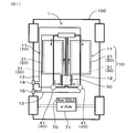
- FIG. 1 is a conceptual diagram illustrating a configuration of a vehicle equipped with a flow battery according to the first embodiment.
- FIG. 2 is a conceptual diagram illustrating a vehicle equipped with a flow battery according to the first embodiment.
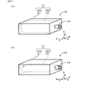
- FIG. 3 is a conceptual diagram illustrating a configuration of a part of a circulatory system according to the first embodiment.
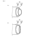
- FIG. 4 is a conceptual diagram showing a configuration of a part of a circulatory system in the second embodiment.
- FIG. 5A and 5B are conceptual diagrams illustrating (a) a partial configuration of a circulatory system viewed from a thickness direction, and (b) a conceptual diagram illustrating a partial configuration of a circulatory system viewed from a longitudinal direction in a third embodiment.
- FIG. 6 is (a) another conceptual diagram showing a part of the circulatory system viewed from a thickness direction, and (b) another diagram showing a part of the circulatory system viewed from a longitudinal direction in the third embodiment.
- FIG. 6 is (a) another conceptual diagram showing a part of the circulatory system viewed from a thickness direction, and (b) another diagram showing a part of the circulatory system viewed from a longitudinal direction in the third embodiment.
- the flow battery 1 of the present embodiment is mounted on a moving medium. At least a part of the circulation system 10 in the flow battery 1 has a double structure including an outer portion 20 forming an outer shape, and an inner portion 30 provided inside the outer portion 20 and storing or circulating an electrolyte. I have. The volume of the inner portion 30 can be changed according to the internal pressure in the circulation system 10.
- the flow battery 1 is mounted on a vehicle 100 as a moving medium.
- the flow battery 1 is a so-called redox flow battery, and includes a battery cell 50 and a circulation system 10 for circulating and supplying an electrolyte to the battery cell 50.
- the battery cell 50 is provided with an anode and a cathode (not shown) separated by a membrane, and is configured so that chemical energy obtained by the electrolyte supplied to each electrode by the circulation system 10 can be taken out as electric energy.
- the vehicle 100 includes a battery, an electric double-layer capacitor (EDLC) 70, and a traction motor system (e-Axle) 71.
- EDLC electric double-layer capacitor
- e-Axle traction motor system
- the circulation system 10 includes a tank 11 and a pipe 12.
- Two tanks 11 are mounted, one of which stores an electrolytic solution supplied to the anode of the battery cell 50, and the other stores an electrolytic solution supplied to the cathode of the battery cell 50.
- the pipe 12 connects the respective tanks 11 and the battery cells 50 to form a flow path through which the electrolyte flows.
- the flow battery 1 of the present embodiment is provided with a pump 41 as an internal pressure control unit 40.
- the pump 41 is provided in the pipe 12, and is configured to control the internal pressure of the circulation system 10 by adjusting the flow state of the electrolytic solution in the pipe 12.
- the pump 41 is connected to the supply port 14 and the discharge port 15 provided in the vehicle 100 by the bypass flow path 13. At the time of replenishment / replacement of the electrolytic solution, replenishment / replacement of the electrolytic solution in the tank 11 can be performed via the supply port 14 and the discharge port 15 via the bypass channel 13.
- the volume of the inner bag 31 as the inner portion 30 decreases with the discharge of the electrolytic solution, and increases with the supply of the electrolytic solution.
- the pump 41 serving as the internal pressure control unit 40 can be operated while the vehicle 100 is stopped.
- the tank 11 as a part of the circulation system 10 has a double structure including an outer portion 20 and an inner portion 30.
- the tank 11 is placed horizontally on the base floor of the vehicle as shown in FIG.
- the tank 11 includes a hard case 21 as an outer portion 20, and an inner bag 31 as an inner portion 30 inside the hard case 21.
- the hard case 21 forms the outer shape of the tank 11 and is maintained in a predetermined shape.
- the inner bag 31 is connected to the pipe 12 and stores the electrolytic solution.
- the inner bag 31 is made of resin and has a variable volume according to the internal pressure of the circulation system 10 as shown in FIGS. 3A and 3B, for example.
- the inner bag 31 when the internal pressure of the circulation system 10 increases, as shown in FIG. 3A, the inner bag 31 expands to increase its volume, and when the internal pressure of the circulation system 10 decreases, as illustrated in FIG. As shown in b), the inner bag 31 contracts and its volume decreases.
- the inner portion 30 is configured such that its volume is reduced as the electrolytic solution is discharged, and is increased as the electrolytic solution is supplied.
- the volume of the inner portion 30 can be changed according to the internal pressure in the circulation system 10 of the flow battery 1. Phases are less likely to occur. As a result, generation of noise due to the waving of the electrolyte in the circulating system 10 is prevented, and defective charging and discharging due to bubbling of the electrolyte is also prevented. Furthermore, since the electrolyte does not easily move even when the vehicle 100 as a moving medium is accelerated, decelerated, and changes direction, the movement of the center of gravity of the vehicle 100 is suppressed, and a decrease in drivability is prevented.
- the internal pressure of the circulating system 10 is hard to fluctuate, scattering from the supply port 14 and the discharge port 15 at the time of electrolyte exchange and entry of foreign matter due to inflow of outside air into the circulating system 10 are prevented. Further, since the outer shape of the tank 11 as the circulating system 10 is formed by the outer portion 20, the shape of the circulating system 10 itself is easily maintained, and the tank 100 is less susceptible to shaking and vibration. .
- the circulating system 10 is provided with a tank 11 for storing an electrolytic solution.
- the tank 11 has a double structure including an outer portion 20 and an inner portion 30. It has an inner bag 31 configured to be variable in volume according to the internal pressure of the tank 11. Thereby, generation of a gas phase in the tank 11 is further suppressed, and undulation and bubbling of the electrolytic solution in the tank 11 are further prevented, and the movement of the center of gravity of the vehicle 100 due to the movement of the electrolytic solution is further suppressed. In addition, a reduction in drivability is further prevented.
- the inner portion 30 is configured such that its volume decreases as the electrolytic solution is discharged, and increases as the electrolytic solution is supplied. Thereby, generation of a gas phase in the circulation system 10 due to replenishment or replacement of the electrolytic solution is suppressed.
- the pump 41 is provided as the internal pressure control unit 40 that controls the internal pressure in the circulation system 10.
- the pump 41 suppresses generation of a gas phase in the circulation system 10 by setting the pressure in the circulation system 10 to a negative pressure.
- a temperature control unit that controls the temperature of the circulation system 10 may be provided as the internal pressure control unit 40 instead of the pump 41.
- the internal pressure of the circulating system 10 is high, the internal pressure of the circulating system 10 is reduced by cooling the circulating system 10 by the temperature control unit to reduce the gas phase volume in the circulating system 10. Can be. This prevents the electrolytic solution from waving and bubbling in the tank 11, and also suppresses the movement of the center of gravity of the vehicle 100 due to the movement of the electrolytic solution, thereby preventing a decrease in drivability.
- the pump 41 serving as the internal pressure control unit 40 is configured to operate while the vehicle 100 is stopped. Thus, it is possible to suppress the electrolytic solution from scattering outside when the vehicle is running.
- the four-wheeled vehicle 100 is used as the moving medium on which the flow battery 1 is mounted.
- a two-wheeled vehicle such as a motorcycle, a train, or a ship may be used.
- the flow battery 1 suitable for being mounted on a moving medium such as the vehicle 100.
- the tank 11 has a double structure as shown in FIGS. 3 (a) and 3 (b).
- the pipe 12 may have a double structure including the outer tube 22 as the outer portion 20 and the inner tube 32 as the inner portion 30 provided inside the outer tube 22.
- the outer pipe 22 forms the outer shape of the pipe 12, and the inner pipe 32 is formed of a highly flexible material.
- the inner pipe 32 is configured to be variable in volume according to the internal pressure of the circulating system 10. In the present embodiment, when the internal pressure of the circulating system 10 increases, as shown in FIG.
- the inner pipe 32 expands to increase its volume, and when the internal pressure of the circulating system 10 decreases, as shown in FIG. As shown in FIG. 4 (b), the inner tube 32 contracts and its volume decreases.
- the other components are the same as in the first embodiment, and the same reference numerals as in the first embodiment denote the same components in the present embodiment, and a description thereof will be omitted.
- the present embodiment by forming the pipe 12 with the above-described double structure, generation of a gas phase in the circulation system 10 including the tank 11 can be suppressed. As a result, the present embodiment also has the same operation and effect as the first embodiment.
- a case 23 is provided as an outer portion 20 of the tank 11, and an inner bag as an inner portion 30 is provided inside the case 23. 33 is provided.
- the inner bag 33 is made of resin similarly to the inner bag 31 of the first embodiment, and has a variable volume.
- the case 23 has higher rigidity than the inner bag 33, but is configured to be elastically deformable.
- Engagement projections 24 are provided on both side walls of the case 23.
- a rod-shaped shaft member 60 is disposed on each side of the case 23. One end of the shaft member 60 is connected to a motor 61, and the shaft member 60 can be reciprocated in the longitudinal direction Y of the shaft member 60 by the motor 61.
- the engagement protrusion 24 of the case 23 and the shaft member 60 are connected via a link 63.
- the link 63 and the engaging projection 24 are engaged by a pin 64 and are rotatable about the pin 64.
- the link 63 and the shaft member 60 are engaged with each other by a pin 65 and are rotatable around the pin 65.
- the drive of the motor 61 is controlled by a motor drive control unit 42 as the internal pressure control unit 40.
- an internal pressure detection unit 43 detects an internal pressure in the circulating system 10.
- the comparing unit 44 compares the detection result of the internal pressure detecting unit with a preset reference value.
- the reference value may be the atmospheric pressure, but may be appropriately changed according to the configuration of the flow battery 1, the type of the electrolyte, the operating conditions of the vehicle 100, and the like.
- the output unit 45 outputs the comparison result of the comparison unit 44. In the present embodiment, the output unit 45 outputs the comparison result to the motor drive control unit 42, and the motor drive control unit 42 controls the drive of the motor 61 based on the comparison result.
- the comparison result is output to the motor drive control unit 42.
- the motor 61 is driven by the motor drive control unit 42 to move the shaft member 60 to one side Y1 in the longitudinal direction Y.
- the case 23 of the tank 11 is pulled outward through the link 63 in the width direction X orthogonal to the longitudinal direction Y.
- the inner bag 33 of the tank 11 spreads outward in the width direction X and the width W1 increases, but is pushed inward by the case 23 in the thickness direction Z. Therefore, the height H1 becomes smaller.
- the volume of the inner bag 33 becomes smaller, and the inner pressure of the circulation system 10 rises and approaches the reference value.
- the comparison result indicates that the internal pressure of the circulation system 10 detected by the internal pressure detection unit 43 is higher than the reference value by the comparison unit 44
- the comparison result is output to the motor drive control unit 42.
- the motor 61 is driven by the motor drive controller 42 to move the shaft member 60 to the other side Y2 in the longitudinal direction Y.
- the case 23 of the tank 11 is pushed inward in the width direction X via the link 63.
- the inner bag 33 of the tank 11 is pushed inward in the width direction X and the width W2 is reduced, but the case 23 expands outward in the thickness direction Z.
- the height H2 increases.
- the volume of the inner bag 33 increases, and the internal pressure of the circulation system 10 decreases to approach the reference value.
- the output unit 45 outputs the comparison result to the motor drive control unit 42, and the motor drive control unit 42 controls the drive of the motor 61 based on the comparison result.
- the output unit 45 displays the comparison result on a predetermined display unit, notifies the user of the comparison result, or locks the supply port 14 and the discharge port 15 so as not to open. Is also good.
- the present disclosure is not limited to the above embodiments, and can be applied to various embodiments without departing from the gist of the present disclosure.
- the configuration of the shaft member 60, the motor 61, and the link 63 in the third embodiment may be applied to the pipe 12 in the second embodiment.
Landscapes
- Engineering & Computer Science (AREA)
- Sustainable Development (AREA)
- Power Engineering (AREA)
- Sustainable Energy (AREA)
- Life Sciences & Earth Sciences (AREA)
- Chemical & Material Sciences (AREA)
- Mechanical Engineering (AREA)
- Transportation (AREA)
- Manufacturing & Machinery (AREA)
- Chemical Kinetics & Catalysis (AREA)
- Electrochemistry (AREA)
- General Chemical & Material Sciences (AREA)
- Fuel Cell (AREA)
- Combustion & Propulsion (AREA)
- Electric Propulsion And Braking For Vehicles (AREA)
- Arrangement Or Mounting Of Propulsion Units For Vehicles (AREA)
Abstract
フロー電池(1)は、移動媒体に搭載される。フロー電池(1)における循環系(10)の少なくとも一部は、外形を形成する外側部(20)と、外側部(20)の内側に設けられるとともに電解液が貯留又は流通する内側部(30)とからなる二重構造をなしている。そして、内側部(30)は循環系(10)内における内圧に応じてその容積が変化可能に構成されている。
Description
本出願は2018年7月4日に出願された日本出願番号2018-127391号に基づくもので、ここにその記載内容を援用する。
本開示は、フロー電池に関する。
大型の定置用電源の二次電池として、タンクに蓄えた電解液をポンプにより電池セルに循環供給して充放電させるフロー電池が用いられている。例えば、特許文献1には、タンク内の気相部に外気と連動して膨張・収縮する呼吸袋を備えたフロー電池が開示されている。かかる構成では、タンク内が外気よりも負圧状態のときには呼吸袋に外気を流入させて呼吸袋を膨張させることにより、タンクの電解液を外気に触れさせることなくタンク内の負圧を解消している。一方、タンク内が外気よりも高圧状態のときには、呼吸袋を収縮させることにより、タンク内の気化した電解液を外部に放出することなくタンク内を外気と同等の圧力にしている。これらにより、タンク内の圧力変動を抑制している。
特許文献1に開示の構成では、タンク内の圧力変動を抑制するためには、呼吸袋をタンクの気相部に設けることが必要となる。そして、かかるフロー電池を四輪車や二輪車を含む車両の電源として搭載すると、タンクを横置きする必要があることから、車両の振動によって気相部を有するタンク内の電解液が波打って騒音が発生して車両の静音性を低下させるとともに、電解液に多数の気泡が発生して充放電不良を招く。さらに、車両の加速時、減速時及び方向転換時には電解液が慣性によって一方に移動して車両の重心移動が生じるため、ドライバビリティを低下させる。また、メンテナンスや解体の際には、タンク内が気体のみになり圧力変動が最大になることを考慮する必要もある。また車両の運転等による温度上昇に伴ってタンクの内圧が過剰に高くなると、電解液の交換時に供給口を開く際に電解液が飛散する恐れがある。一方、温度低下に伴ってタンクの内圧が低下すると電解液の交換時に外気がタンク内に取り込まれて異物が混入する恐れがある。以上のように、フロー電池を車両に搭載するには改善の余地がある。
本開示は、車両等の移動媒体に搭載するのに適したフロー電池を提供しようとするものである。
本開示の一態様は、電池セルと、該電池セルに供給される電解液を循環させる循環系とを有し、移動媒体に搭載されるように構成されたフロー電池であって、
上記循環系の少なくとも一部は、外形を形成する外側部と、該外側部の内側に設けられるとともに上記電解液を貯留又は流通する内側部とからなる二重構造を有しており、
上記内側部は上記循環系の内圧に応じて容積可変に構成されている、フロー電池にある。
上記循環系の少なくとも一部は、外形を形成する外側部と、該外側部の内側に設けられるとともに上記電解液を貯留又は流通する内側部とからなる二重構造を有しており、
上記内側部は上記循環系の内圧に応じて容積可変に構成されている、フロー電池にある。
上記フロー電池においては、内側部の容積はフロー電池の循環系内における内圧に応じて変化可能となっているため、タンクや配管を含む循環系に気相が発生しにくくなっている。その結果、循環系内で電解液の波打ちに起因する騒音の発生が防止されるとともに、電解液の泡立ちに起因する充放電不良も防止される。さらに、車両等の移動媒体の加速時、減速時及び方向転換時においても電解液が移動しにくいため、車両等の移動媒体の重心移動が抑制され、ドライバビリティの低下が防止される。さらに、循環系の内圧が変動しにくいため、電解液交換時の給液口からの飛散や循環系内への外気流入に起因する異物の混入が防止される。また、循環系の外形は外側部により形成されているため、循環系自体の形状が維持されやすくなっており、車両等の移動媒体の揺れや振動の影響を受けにくくなっている。
以上のごとく、本開示によれば、車両等の移動媒体に搭載するのに適したフロー電池を提供することができる。
なお、請求の範囲に記載した括弧内の符号は、後述する実施形態に記載の具体的手段との対応関係を示すものであり、本開示の技術的範囲を限定するものではない。
本開示についての上記目的及びその他の目的、特徴や利点は、添付の図面を参照しながら下記の詳細な記述により、より明確になる。その図面は、
図1は、実施形態1における、フロー電池が搭載された車両の構成を示す概念図であり、
図2は、実施形態1における、フロー電池が搭載された車両を示す概念図であり、
図3は、実施形態1における、循環系の一部の構成を示す概念図であり、
図4は、実施形態2における、循環系の一部の構成を示す概念図であり、
図5は、実施形態3における、(a)厚さ方向から見た循環系の一部の構成を示す概念図、(b)長手方向から見た循環系の一部の構成を示す概念図であり、
図6は、実施形態3における、(a)厚さ方向から見た循環系の一部の構成を示す他の概念図、(b)長手方向から見た循環系の一部の構成を示す他の概念図である。
(実施形態1)
上記フロー電池の実施形態について、図1~図3を用いて説明する。
本実施形態のフロー電池1は、移動媒体に搭載される。
フロー電池1における循環系10の少なくとも一部は、外形を形成する外側部20と、外側部20の内側に設けられるとともに電解液が貯留又は流通する内側部30とからなる二重構造をなしている。
そして、内側部30は循環系10内における内圧に応じてその容積が変化可能に構成されている。
上記フロー電池の実施形態について、図1~図3を用いて説明する。
本実施形態のフロー電池1は、移動媒体に搭載される。
フロー電池1における循環系10の少なくとも一部は、外形を形成する外側部20と、外側部20の内側に設けられるとともに電解液が貯留又は流通する内側部30とからなる二重構造をなしている。
そして、内側部30は循環系10内における内圧に応じてその容積が変化可能に構成されている。
以下、本実施形態のフロー電池1の構成について詳述する。
本実施形態のフロー電池1は、図1に示すように、移動媒体としての車両100に搭載されている。フロー電池1はいわゆるレドックスフロー電池であって、電池セル50と、電池セル50に電解液を循環供給させる循環系10を備える。電池セル50には図示しない陽極及び陰極が膜を隔てて配置されており、循環系10により各電極に供給された電解液により得られる化学エネルギーを電気エネルギーとして取り出すことができるように構成されている。なお、車両100には、バッテリー及び電気二重層コンデンサ(Electric double-layer capacitor、EDLC)70、トラクションモータシステム(e-Axle)71が搭載されている。
本実施形態のフロー電池1は、図1に示すように、移動媒体としての車両100に搭載されている。フロー電池1はいわゆるレドックスフロー電池であって、電池セル50と、電池セル50に電解液を循環供給させる循環系10を備える。電池セル50には図示しない陽極及び陰極が膜を隔てて配置されており、循環系10により各電極に供給された電解液により得られる化学エネルギーを電気エネルギーとして取り出すことができるように構成されている。なお、車両100には、バッテリー及び電気二重層コンデンサ(Electric double-layer capacitor、EDLC)70、トラクションモータシステム(e-Axle)71が搭載されている。
図1に示すように、循環系10は、タンク11及び配管12を含む。タンク11は、2つ搭載されており、一方には電池セル50の陽極に供給される電解液が貯留され、他方には電池セル50の陰極に供給される電解液が貯留されている。配管12は各タンク11と電池セル50とを接続して電解液を流通させる流路を形成している。
図1に示すように、本実施形態のフロー電池1には、内圧制御部40としてのポンプ41が設けられている。ポンプ41は配管12に設けられて、配管12における電解液の流通状態を調整して、循環系10の内圧を制御するように構成されている。また、ポンプ41はバイパス流路13により車両100に備えられた供給口14及び排出口15に接続されている。電解液の補充・交換時には、バイパス流路13を介して供給口14、排出口15を介してタンク11内の電解液の補充・交換が可能となっている。そして、電解液の補充・交換時には、内側部30としての内袋31は、電解液の排出に伴ってその容積が縮小し、電解液の供給に伴ってその容積が増大することとなる。内圧制御部40としてのポンプ41は、車両100の停止中に作動するようにすることができる。
本実施形態では図1に示すように、循環系10の一部としてのタンク11が外側部20と内側部30とからなる二重構造を有している。タンク11は、図2に示すように、車両のベースフロアに横置きされている。そして、図3(a)、図3(b)に示すように、タンク11は外側部20としてのハードケース21を備え、ハードケース21の内側には内側部30としての内袋31を備えている。ハードケース21はタンク11の外形を形成し所定の形状に維持されている。内袋31は配管12に接続され電解液が貯留される。内袋31は樹脂製であって、例えば、図3(a)、図3(b)に示すように、循環系10の内圧に応じて容積可変となっている。本実施形態では循環系10の内圧が高くなるときには、図3(a)に示すように、内袋31は膨張してその容積が大きくなり、循環系10の内圧が低くなるときには、図3(b)に示すように、内袋31は収縮してその容積が小さくなる。内側部30は、電解液の排出に伴ってその容積が縮小し、電解液の供給に伴ってその容積が増大するように構成されている。
次に、本実施形態のフロー電池1における作用効果について、詳述する。
本実施形態のフロー電池1によれば、内側部30の容積はフロー電池1の循環系10内における内圧に応じて変化可能となっているため、タンク11や配管12を含む循環系10に気相が発生しにくくなっている。その結果、循環系10内で電解液の波打ちに起因する騒音の発生が防止されるとともに、電解液の泡立ちに起因する充放電不良も防止される。さらに、移動媒体としての車両100の加速時、減速時及び方向転換時においても電解液が移動しにくいため、車両100の重心移動が抑制され、ドライバビリティの低下が防止される。さらに、循環系10の内圧が変動しにくいため、電解液交換時の供給口14や排出口15からの飛散や循環系10内への外気流入に伴う異物の混入が防止される。また、循環系10としてのタンク11の外形は外側部20により形成されているため、循環系10自体の形状が維持されやすくなっており、車両100の揺れや振動の影響を受けにくくなっている。
本実施形態のフロー電池1によれば、内側部30の容積はフロー電池1の循環系10内における内圧に応じて変化可能となっているため、タンク11や配管12を含む循環系10に気相が発生しにくくなっている。その結果、循環系10内で電解液の波打ちに起因する騒音の発生が防止されるとともに、電解液の泡立ちに起因する充放電不良も防止される。さらに、移動媒体としての車両100の加速時、減速時及び方向転換時においても電解液が移動しにくいため、車両100の重心移動が抑制され、ドライバビリティの低下が防止される。さらに、循環系10の内圧が変動しにくいため、電解液交換時の供給口14や排出口15からの飛散や循環系10内への外気流入に伴う異物の混入が防止される。また、循環系10としてのタンク11の外形は外側部20により形成されているため、循環系10自体の形状が維持されやすくなっており、車両100の揺れや振動の影響を受けにくくなっている。
また、本実施形態では、循環系10には電解液を貯留するタンク11が備えられており、タンク11は、外側部20と内側部30とからなる二重構造を有するとともに、内側部30としてタンク11の内圧に応じて容積可変に構成された内袋31を有する。これにより、タンク11に気相が発生することが一層抑制され、タンク11内での電解液の波打ちや泡立ちが一層防止されるとともに、電解液の移動に伴う車両100の重心移動も一層抑制され、ドライバビリティの低下がさらに防止される。
また、本実施形態では、内側部30は、電解液の排出に伴ってその容積が縮小し、電解液の供給に伴ってその容積が増大するように構成されている。これにより、電解液の補充や交換に起因して循環系10内に気相が発生することが抑制される。
また、本実施形態では、循環系10における内圧を制御する内圧制御部40としてポンプ41を有する。当該ポンプ41により、循環系10内の圧力を負圧にして循環系10内に気相が発生することが抑制される。なお、内圧制御部40としてポンプ41に替えて、循環系10の温度を制御する温度制御部を備えていてもよい。この場合は、循環系10の内圧が高い場合には、当該温度制御部によって循環系10を冷却することにより、循環系10の内圧を低下させて循環系10内の気相容積を低減することができる。これにより、タンク11内での電解液の波打ちや泡立ちが防止されるとともに、電解液の移動に伴う車両100の重心移動も抑制され、ドライバビリティの低下が防止される。
また、本実施形態では、内圧制御部40としてのポンプ41は、車両100の停止中に作動するように構成されている。これにより、車両走行時に電解液が外部に飛散することを抑制できる。
なお、本実施形態ではフロー電池1が搭載される移動媒体として、四輪の車両100としたが、これに替えて、バイクなどの二輪車であってもよいし、列車や船舶であってよい。
以上のごとく、本実施形態によれば、車両100等の移動媒体に搭載するのに適したフロー電池1を提供することができる。
(実施形態2)
実施形態1のフロー電池1では、図3(a)、図3(b)に示すようにタンク11を二重構造としたが、これに替えて又はこれとともに、図4(a)、図4(b)に示す本実施形態のように配管12が外側部20としての外管22と、外管22の内側に設けられる内側部30としての内管32とからなる二重構造としてもよい。本実施形態では、外管22が配管12の外形を形成しており、内管32は柔軟性の高い材料から形成されている。これにより、図4(a)、図4(b)に示すように、内管32は循環系10の内圧に応じて容積可変に構成されている。そして、本実施形態では循環系10の内圧が高くなるときには、図4(a)に示すように、内管32は膨張してその容積が大きくなり、循環系10の内圧が低くなるときには、図4(b)に示すように、内管32は収縮してその容積が小さくなる。その他の構成要素は実施形態1の場合と同様であり、本実施形態においても実施形態1の場合と同一の符号を用いてその説明を省略する。
実施形態1のフロー電池1では、図3(a)、図3(b)に示すようにタンク11を二重構造としたが、これに替えて又はこれとともに、図4(a)、図4(b)に示す本実施形態のように配管12が外側部20としての外管22と、外管22の内側に設けられる内側部30としての内管32とからなる二重構造としてもよい。本実施形態では、外管22が配管12の外形を形成しており、内管32は柔軟性の高い材料から形成されている。これにより、図4(a)、図4(b)に示すように、内管32は循環系10の内圧に応じて容積可変に構成されている。そして、本実施形態では循環系10の内圧が高くなるときには、図4(a)に示すように、内管32は膨張してその容積が大きくなり、循環系10の内圧が低くなるときには、図4(b)に示すように、内管32は収縮してその容積が小さくなる。その他の構成要素は実施形態1の場合と同様であり、本実施形態においても実施形態1の場合と同一の符号を用いてその説明を省略する。
本実施形態では、配管12を上記二重構造とすることにより、タンク11を含む循環系10内に気相が生じることを抑制できる。これにより、本実施形態においても実施形態1の場合と同等の作用効果を奏する。
(実施形態3)
本実施形態においても、実施形態1の構成に加えて、図5、図6に示すように、タンク11の外側部20としてのケース23を備え、ケース23の内側に内側部30としての内袋33を備える。内袋33は実施形態1の内袋31と同様に樹脂製であって、容積可変となっている。ケース23は、内袋33よりも剛性が高いが、弾性変形可能に構成されている。ケース23の両側壁には係合突起24が設けられている。ケース23の両側にはそれぞれ棒状の軸部材60が配設されている。軸部材60の一端はモータ61に接続されており、軸部材60はモータ61により軸部材60の長手方向Yに往復移動可能となっている。そして、ケース23の係合突起24と軸部材60はリンク63を介して接続されている。リンク63と係合突起24はピン64により係合されて該ピン64を中心に回転可能となっている。同様にリンク63と軸部材60はピン65により係合されて該ピン65を中心に回転可能となっている。そして、モータ61は内圧制御部40としてのモータ駆動制御部42により駆動制御されている。
本実施形態においても、実施形態1の構成に加えて、図5、図6に示すように、タンク11の外側部20としてのケース23を備え、ケース23の内側に内側部30としての内袋33を備える。内袋33は実施形態1の内袋31と同様に樹脂製であって、容積可変となっている。ケース23は、内袋33よりも剛性が高いが、弾性変形可能に構成されている。ケース23の両側壁には係合突起24が設けられている。ケース23の両側にはそれぞれ棒状の軸部材60が配設されている。軸部材60の一端はモータ61に接続されており、軸部材60はモータ61により軸部材60の長手方向Yに往復移動可能となっている。そして、ケース23の係合突起24と軸部材60はリンク63を介して接続されている。リンク63と係合突起24はピン64により係合されて該ピン64を中心に回転可能となっている。同様にリンク63と軸部材60はピン65により係合されて該ピン65を中心に回転可能となっている。そして、モータ61は内圧制御部40としてのモータ駆動制御部42により駆動制御されている。
さらに、図5(a)に示すように、内圧検出部43、比較部44、出力部45を備える。内圧検出部43は、循環系10における内圧を検出する。比較部44は、内圧検出部の検出結果と予め設定された基準値とを比較する。当該基準値は大気圧とすることができるが、フロー電池1の構成、電解液の種類、車両100の運転条件等に応じて、適宜変更してもよい。出力部45は、比較部44の比較結果を出力する。本実施形態では、出力部45は比較結果をモータ駆動制御部42に出力し、モータ駆動制御部42は当該比較結果に基づいて、モータ61の駆動制御を行う。
内圧検出部43によって検出された循環系10の内圧が、比較部44により基準値よりも低いことを示す比較結果が示された場合は、当該比較結果がモータ駆動制御部42に出力され、図5(a)に示すように、モータ駆動制御部42により、モータ61が駆動されて、軸部材60を長手方向Yの一方側Y1に移動させる。これにより、リンク63を介してタンク11のケース23は長手方向Yに直交する幅方向Xの外方に向けて引っ張られることとなる。その結果、図5(b)に示すように、タンク11の内袋33は、幅方向Xの外方に広がって幅W1は大きくなるが、ケース23により厚さ方向Zにおいて内方に押されて高さH1は小さくなる。その結果、内袋33の容積は小さくなって、循環系10の内圧は上昇して基準値に近づくこととなる。
一方、内圧検出部43によって検出された循環系10の内圧が、比較部44により基準値よりも高いことを示す比較結果が示された場合は、当該比較結果がモータ駆動制御部42に出力され、図6(a)に示すように、モータ駆動制御部42により、モータ61が駆動されて、軸部材60を長手方向Yの他方側Y2に移動させる。これにより、リンク63を介してタンク11のケース23は幅方向Xの内方に向けて押されることとなる。その結果、図6(b)に示すように、タンク11の内袋33は、幅方向Xの内方に押されて幅W2は小さくなるが、ケース23により厚さ方向Zにおいて外方に広がり高さH2は大きくなる。その結果、内袋33の容積は大きくなって、循環系10の内圧は低下して基準値に近づくこととなる。
本実施形態におけるその他の構成要素は実施形態1の場合と同様であり、本実施形態においても実施形態1の場合と同一の符号を用いてその説明を省略する。そして、本実施形態によれば、内側部30としての内袋33は内圧制御部40としてのモータ駆動制御部42によりその容積が可変となっているため、実施形態1の場合と同等の作用効果を奏する。
なお、本実施形態では、出力部45は比較結果をモータ駆動制御部42に出力し、モータ駆動制御部42は当該比較結果に基づいて、モータ61の駆動制御を行うようにしたが、これに替えて、又はこれとともに、出力部45は比較結果を所定の表示部に表示して、使用者に比較結果を報知したり、供給口14や排出口15が開かないようにロックしたりしてもよい。
本開示は上記各実施形態に限定されるものではなく、その要旨を逸脱しない範囲において種々の実施形態に適用することが可能である。例えば、実施形態3における軸部材60、モータ61、リンク63の構成を実施形態2の配管12に適用してもよい。
本開示は、実施形態に準拠して記述されたが、本開示は当該実施形態や構造に限定されるものではないと理解される。本開示は、様々な変形形態や均等範囲内の変形をも包含する。加えて、様々な組み合わせや形態、さらには、それらに一要素のみ、それ以上、あるいはそれ以下、を含む他の組み合わせや形態をも、本開示の範疇や思想範囲に入るものである。
Claims (7)
- 電池セル(50)と、該電池セルに供給される電解液を循環させる循環系(10)とを有し、移動媒体(100)に搭載されるように構成されたフロー電池(1)であって、
上記循環系の少なくとも一部は、外形を形成する外側部(20)と、該外側部の内側に設けられるとともに上記電解液を貯留又は流通する内側部(30)とからなる二重構造を有しており、
上記内側部は上記循環系の内圧に応じて容積可変に構成されている、フロー電池。 - 上記循環系には上記電解液を貯留するタンク(11)が備えられており、
該タンクは、上記二重構造を有するとともに、上記内側部として上記タンクの内圧に応じて容積可変に構成された内袋(31、33)を有する、請求項1に記載のフロー電池。 - 上記循環系には上記電解液を流通させる配管(12)が備えられており、該配管は上記二重構造を有するとともに、上記内側部として上記配管の内圧に応じて容積が変化可能な内管(32)を有する、請求項1又は2に記載のフロー電池。
- 上記内側部は、上記電解液の排出に伴ってその容積が縮小し、上記電解液の供給に伴ってその容積が増大するように構成されている、請求項1~3のいずれか一項に記載のフロー電池。
- 上記循環系における内圧を制御する内圧制御部(40)を有する、請求項1~4のいずれか一項に記載のフロー電池。
- 上記内圧制御部は、上記移動媒体が停止中に作動するように構成されている、請求項5に記載のフロー電池。
- 上記循環系における内圧を検出する内圧検出部(43)と、該内圧検出部の検出結果と予め設定された基準値とを比較する比較部(44)と、該比較部の比較結果を出力する出力部(45)とを備える、請求項1~6のいずれか一項に記載のフロー電池。
Applications Claiming Priority (2)
| Application Number | Priority Date | Filing Date | Title |
|---|---|---|---|
| JP2018-127391 | 2018-07-04 | ||
| JP2018127391A JP2020009558A (ja) | 2018-07-04 | 2018-07-04 | フロー電池 |
Publications (1)
| Publication Number | Publication Date |
|---|---|
| WO2020008814A1 true WO2020008814A1 (ja) | 2020-01-09 |
Family
ID=69060243
Family Applications (1)
| Application Number | Title | Priority Date | Filing Date |
|---|---|---|---|
| PCT/JP2019/023005 Ceased WO2020008814A1 (ja) | 2018-07-04 | 2019-06-11 | フロー電池 |
Country Status (2)
| Country | Link |
|---|---|
| JP (1) | JP2020009558A (ja) |
| WO (1) | WO2020008814A1 (ja) |
Citations (1)
| Publication number | Priority date | Publication date | Assignee | Title |
|---|---|---|---|---|
| JPS62271360A (ja) * | 1986-05-16 | 1987-11-25 | Sumitomo Electric Ind Ltd | 電解液流通型2次電池 |
-
2018
- 2018-07-04 JP JP2018127391A patent/JP2020009558A/ja active Pending
-
2019
- 2019-06-11 WO PCT/JP2019/023005 patent/WO2020008814A1/ja not_active Ceased
Patent Citations (1)
| Publication number | Priority date | Publication date | Assignee | Title |
|---|---|---|---|---|
| JPS62271360A (ja) * | 1986-05-16 | 1987-11-25 | Sumitomo Electric Ind Ltd | 電解液流通型2次電池 |
Also Published As
| Publication number | Publication date |
|---|---|
| JP2020009558A (ja) | 2020-01-16 |
Similar Documents
| Publication | Publication Date | Title |
|---|---|---|
| JP6582011B2 (ja) | 燃料電池システムを備えた輸送機器 | |
| US20210135255A1 (en) | Freight vehicle | |
| JP6447838B2 (ja) | 燃料電池車両 | |
| KR20160052699A (ko) | 하이브리드 차량 및 하이브리드 차량의 제어 방법 | |
| JPWO2017017867A1 (ja) | 冷却装置 | |
| JP6662462B2 (ja) | 機器温調装置 | |
| US20210104756A1 (en) | Fuel cell vehicle | |
| US11296345B2 (en) | Air cleaner | |
| JP5812423B2 (ja) | 燃料電池システム | |
| WO2020008814A1 (ja) | フロー電池 | |
| JP6948270B2 (ja) | 産業車両用の燃料電池システム | |
| US10525840B2 (en) | Fuel cell vehicle | |
| JP6237426B2 (ja) | 燃料電池システム | |
| WO2015174282A1 (ja) | レドックスフロー電池 | |
| CA2867426A1 (en) | Fuel cell system with setup of upper pressure of anode gas | |
| JP6136022B2 (ja) | 燃料電池車の制御方法 | |
| JP4556619B2 (ja) | 燃料電池システム | |
| JP2012238551A (ja) | 燃料電池の冷却システム | |
| JP5437089B2 (ja) | 燃料電池システム | |
| US20190013531A1 (en) | Fuel cell module | |
| US9461317B2 (en) | Fuel cell system and control method therefor | |
| JP2018174031A (ja) | 燃料電池車両 | |
| JP6186989B2 (ja) | 燃料電池システム | |
| JP2021163700A (ja) | 燃料電池システム | |
| JP2005347087A (ja) | 燃料電池システムおよびこれを備える動力出力装置並びに燃料電池車 |
Legal Events
| Date | Code | Title | Description |
|---|---|---|---|
| 121 | Ep: the epo has been informed by wipo that ep was designated in this application |
Ref document number: 19829849 Country of ref document: EP Kind code of ref document: A1 |
|
| NENP | Non-entry into the national phase |
Ref country code: DE |
|
| 122 | Ep: pct application non-entry in european phase |
Ref document number: 19829849 Country of ref document: EP Kind code of ref document: A1 |