WO2020008808A1 - ガスセンサ - Google Patents
ガスセンサ Download PDFInfo
- Publication number
- WO2020008808A1 WO2020008808A1 PCT/JP2019/022852 JP2019022852W WO2020008808A1 WO 2020008808 A1 WO2020008808 A1 WO 2020008808A1 JP 2019022852 W JP2019022852 W JP 2019022852W WO 2020008808 A1 WO2020008808 A1 WO 2020008808A1
- Authority
- WO
- WIPO (PCT)
- Prior art keywords
- gas
- solid electrolyte
- sensor element
- wiring
- layer
- Prior art date
- Legal status (The legal status is an assumption and is not a legal conclusion. Google has not performed a legal analysis and makes no representation as to the accuracy of the status listed.)
- Ceased
Links
Images




Classifications
-
- G—PHYSICS
- G01—MEASURING; TESTING
- G01N—INVESTIGATING OR ANALYSING MATERIALS BY DETERMINING THEIR CHEMICAL OR PHYSICAL PROPERTIES
- G01N27/00—Investigating or analysing materials by the use of electric, electrochemical, or magnetic means
- G01N27/26—Investigating or analysing materials by the use of electric, electrochemical, or magnetic means by investigating electrochemical variables; by using electrolysis or electrophoresis
- G01N27/28—Electrolytic cell components
-
- G—PHYSICS
- G01—MEASURING; TESTING
- G01N—INVESTIGATING OR ANALYSING MATERIALS BY DETERMINING THEIR CHEMICAL OR PHYSICAL PROPERTIES
- G01N27/00—Investigating or analysing materials by the use of electric, electrochemical, or magnetic means
- G01N27/26—Investigating or analysing materials by the use of electric, electrochemical, or magnetic means by investigating electrochemical variables; by using electrolysis or electrophoresis
- G01N27/403—Cells and electrode assemblies
- G01N27/406—Cells and probes with solid electrolytes
- G01N27/407—Cells and probes with solid electrolytes for investigating or analysing gases
-
- G—PHYSICS
- G01—MEASURING; TESTING
- G01N—INVESTIGATING OR ANALYSING MATERIALS BY DETERMINING THEIR CHEMICAL OR PHYSICAL PROPERTIES
- G01N27/00—Investigating or analysing materials by the use of electric, electrochemical, or magnetic means
- G01N27/26—Investigating or analysing materials by the use of electric, electrochemical, or magnetic means by investigating electrochemical variables; by using electrolysis or electrophoresis
- G01N27/416—Systems
Definitions
- the present disclosure relates to a gas sensor.
- NO nitric oxide
- NO 2 nitrogen dioxide
- the sensor element for detecting NO 2 is constituted by a mixed potential type measurement cell having a solid electrolyte layer, a metal oxide detection electrode and a metal reference electrode disposed on the solid electrolyte layer (Patent) Reference 1).
- Patent Document 2 A gas sensor in which a plurality of measurement cells are connected in series by metal wiring for the purpose of miniaturization and improvement of sensitivity is known (see Patent Document 2).
- NOx is activated by a metal constituting a wiring connecting the measurement cells, and the NO 2 / NO ratio of the gas to be measured adjusted by the catalyst becomes an equilibrium ratio at the sensor element temperature. Get closer.
- the output of the sensor element decreases due to the decrease in the NO 2 / NO ratio near the measurement cell. Further, the NO 2 / NO ratio in the vicinity of the measurement cell becomes different from the known value depending on the adjustment value by the catalyst or the history of the atmosphere to be measured, so that the total NOx amount cannot be measured correctly.
- One aspect of the present disclosure is to provide a gas sensor that can suppress a change in the NO 2 / NO ratio due to wiring of a sensor element.
- the gas sensor includes a catalyst unit that converts NO contained in the gas to be measured into NO 2 , a sensor element that detects NO 2 in the gas to be measured that has passed through the catalyst unit, and at least one that heats the catalyst unit and the sensor element. And two heaters.
- the sensor element has a base material, a plurality of measurement cells and a plurality of terminals disposed on the surface of the base material, and a plurality of wirings formed of metal and connecting the plurality of measurement cells and the plurality of terminals in series, And at least one wiring coating layer that covers at least a part of the surface of the plurality of wirings.
- each of the plurality of measurement cells includes a solid electrolyte layer, a detection electrode mainly composed of a metal oxide disposed directly or via a metal layer on the solid electrolyte layer, and a solid electrolyte layer separated from the detection electrode.
- At least one wiring coating layer has lower activity on NOx than a plurality of wirings.
- the sensor element may further include at least one electrode coating layer that covers at least a part of the surface of the reference electrode in at least one of the plurality of measurement cells. At least one electrode coating layer may have lower activity on NOx than the reference electrode. According to such a configuration, since the activity of NOx by the reference electrode can be suppressed by the electrode coating layer, a change in the NO 2 / NO ratio can be more reliably suppressed.
- At least one electrode coating layer may have higher NOx permeability than at least one wiring coating layer. According to such a configuration, the reference electrode can be reliably exposed to the NOx atmosphere while suppressing the NOx activity by the reference electrode.
- the reference electrode in at least one of the plurality of measurement cells, is disposed on the surface of the substrate, and at least a part of the surface that does not contact the substrate by the solid electrolyte layer. May be coated. According to such a configuration, the activity of NOx by the reference electrode can be suppressed by the solid electrolyte layer, so that the change in the NO 2 / NO ratio can be more reliably suppressed. In addition, since the solid electrolyte layer is porous, the reference electrode can be exposed to a NOx atmosphere.
- the reference electrode in at least one of the plurality of measurement cells, is disposed on the surface of the substrate via a gas-permeable diffusion layer laminated on the surface of the substrate. It may be. According to such a configuration, the activity of NOx by the reference electrode can be suppressed by the solid electrolyte layer, so that the change in the NO 2 / NO ratio can be more reliably suppressed. Further, by providing a diffusion layer on the surface of the base material and bringing the diffusion layer into contact with the reference electrode, the reference electrode can be reliably exposed to the NOx atmosphere. Therefore, it is not necessary to form the solid electrolyte layer in a porous state.
- the plurality of measurement cells may be arranged on the same surface of the substrate.
- the at least one wiring coating layer may cover a portion of the plurality of wirings included in a gas passage region through which the gas to be measured that has passed through the catalyst unit passes. According to such a configuration, a portion of the wiring that comes into contact with the gas to be measured is covered, so that a change in the NO 2 / NO ratio can be more reliably suppressed.
- the plurality of terminals may be arranged outside the gas passage area. According to such a configuration, a change in the NO 2 / NO ratio due to the plurality of terminals can be avoided without covering the plurality of terminals.
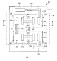
- FIG. 2 is a schematic plan view showing a sensor element 3A of the gas sensor 1 of FIG.
- FIG. 3 is a schematic sectional view taken along line III-III in FIG. 2.
- FIG. 5 is a schematic sectional view taken along line VV in FIG. 4.
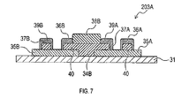
- FIG. 7 is a schematic sectional view taken along line VII-VII in FIG. 6.
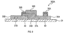
- FIG. 9 is a schematic sectional view taken along line IX-IX in FIG. 8.
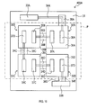
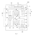
- FIG. 13 is a schematic plan view showing a sensor element 403A of an embodiment different from the first to fifth embodiments. It is a schematic plan view showing sensor element 503A of a 5th embodiment.
- FIG. 12 is a schematic cross-sectional view taken along line CC of FIG. 11.
- the gas sensor 1 shown in FIG. 1 is a gas sensor for measuring the concentration of nitrogen oxide (NOx) contained in the gas G to be measured.
- the gas sensor 1 can be used in fields such as environmental management, process management, and medical care.
- the gas sensor 1 can be suitably used particularly for measurement of a gas containing an extremely low concentration of NOx at a level of several ppb to several hundred ppb, specifically for asthma diagnosis.
- the measured gas G is exhaled gas.
- the gas sensor 1 includes a catalyst unit 2, a sensor unit 3, a heater 5, and three pipes 6, 7, and 8.
- the catalyst unit 2 has a catalyst for chemically changing a component contained in the gas G to be measured.
- the chemical change by the catalyst of the catalyst unit 2 includes converting a certain component to another component and burning a certain component.
- the catalyst of the catalytic unit 2 converts the NO which is the measurement object gas sensor 1 to NO 2, the gas sensor 1 is burned components not measure the concentration. In the case of asthma diagnosis, the catalyst burns a trace amount of miscellaneous gas components contained in the measured gas G, such as CO, H 2 , and VOC.
- the catalyst for example, platinum, rhodium, a noble metal such as gold, a carrier in which particles of the noble metal are supported on, for example, ⁇ -alumina or zeolite, or a metal oxide such as manganese oxide, cobalt oxide, or tin oxide is used.
- a first pipe 6 and a second pipe 7 are connected to the catalyst unit 2.
- the catalyst of the catalyst unit 2 is disposed, for example, in a layered manner on an inner wall (i.e., an inner surface of a flow path connecting the first pipe 6 and the second pipe 7) that forms a flow path of the gas G to be measured in the catalyst unit 2. You.
- the gas to be measured G introduced into the catalyst unit 2 from the first pipe 6 passes through the flow path in the catalyst unit 2 while contacting the catalyst, and is discharged to the second pipe 7.
- the catalyst unit 2 is fixed to the surface of a sensor carrier 3B of the sensor unit 3, which will be described later, by an adhesive 2A.
- the catalyst unit 2 is disposed at a position facing a heater 5 described later with the sensor carrier 3B interposed therebetween.
- an inorganic adhesive or glass can be used as the bonding portion 2A.
- the sensor unit 3 includes a hybrid potential type sensor element 3A for detecting NO 2 in the gas to be measured G that has passed through the catalyst unit 2, a sensor carrier 3B for storing the sensor element 3A, and a cap 3C.
- the sensor element 3A includes a base material 31, a plurality of measurement cells 32A, 32B, 32C, 32D, a plurality of terminals 33A, 33B, and a plurality of wires 34A, 34B, 34C, 34D, 34E, and a plurality of wiring coating layers 38A, 38B, 38C, 38D, 38E.
- the base material 31 is a plate-shaped member mainly composed of ceramic.
- the “main component” means a component contained at 80% by mass or more.
- the ceramic constituting the base material 31 include insulating ceramics such as alumina (Al 2 O 3 ), aluminum nitride (AlN), and silicon nitride (Si 3 N 4 ).
- a plurality of measurement cells 32A, 32B, 32C, 32D, a first terminal 33A and a second terminal 33B, and a plurality of wirings 34A, 34B, 34C, 34D, 34E are arranged on the surface of the base 31. . That is, the measurement cell, the terminal, and the wiring are arranged on the same surface of the base 31.
- the heater 5 shown in FIG. 1 is arranged on the surface of the base 31 opposite to the surface on which the plurality of measurement cells and the like are arranged.
- a plurality of measuring cells 32A, 32B, 32C, 32D constitutes a sensing element for detecting the NO 2.
- the first measurement cell 32A has a first solid electrolyte layer 35A, a first detection electrode 36A, and a first reference electrode 37A.
- the first solid electrolyte layer 35A is disposed on the surface of the base material 31.
- the first solid electrolyte layer 35A is not particularly limited as long as it has oxygen ion conductivity, and for example, a layer containing zirconia as a main component can be used.
- the first detection electrode 36A is disposed on the first solid electrolyte layer 35A via the metal layer 40, as shown in FIG. However, a part or the whole of the first sensing electrode 36A may be directly arranged on the surface of the first solid electrolyte layer 35A.
- the first sensing electrode 36A contains a metal oxide as a main component.
- tungsten oxide WO 3
- the metal layer 40 is made of, for example, a noble metal.
- the first reference electrode 37A is made of a metal disposed on the surface of the first solid electrolyte layer 35A while being separated from the first detection electrode 36A.
- the first reference electrode 37A is made of, for example, a noble metal such as platinum, rhodium, or gold.
- the second measurement cell 32B has a second solid electrolyte layer 35B, a second detection electrode 36B, and a second reference electrode 37B.
- the third measurement cell 32C has a third solid electrolyte layer 35C, a third detection electrode 36C, and a third reference electrode 37C.
- the fourth measurement cell 32D has a fourth solid electrolyte layer 35D, a fourth detection electrode 36D, and a fourth reference electrode 37D.
- the configurations of the second measurement cell 32B, the third measurement cell 32C, and the fourth measurement cell 32D are the same as those of the first measurement cell 32A. Note that the first solid electrolyte layer 35A, the second solid electrolyte layer 35B, the third solid electrolyte layer 35C, and the fourth solid electrolyte layer 35D are arranged on the base material 31 so as to be separated from each other.
- the output of the plurality of measurement cells 32A, 32B, 32C, the sensor element 3A having a 32D will vary based on and the NOx amount NO 2 / NO ratio in the measurement gas G.
- the sensor element 3A detects NO 2 , and the output value (that is, the voltage value) changes according to the NO 2 amount (NO 2 concentration). Since the NO 2 / NO ratio in the inside becomes a constant value based on the chemical equilibrium, the total amount of NOx in the measured gas G can be measured based on the output of the sensor element 3A.
- the number of measurement cells is not limited to four. That is, the sensor element 3A may have two, three, or five or more measurement cells.
- the first terminal 33A and the second terminal 33B are electrode pads for extracting the output of the sensor element 3A. Lead wires and the like are electrically connected to the first terminal 33A and the second terminal 33B, respectively.
- the first terminal 33A and the second terminal 33B are respectively disposed outside the gas passage area P through which the measured gas G that has passed through the catalyst unit 2 passes.
- the “gas passage region P” refers to a measured object in the sensor unit 3 when viewed from the thickness direction of the base material 31 (that is, a direction perpendicular to the surface on which the measurement cells of the base material 31 are arranged). This is an area overlapping the gas G flow path.
- the plurality of wirings 34A, 34B, 34C, 34D, 34E connect the plurality of measurement cells 32A, 32B, 32C, 32D and the plurality of terminals 33A, 33B in series.
- the first wiring 34A electrically connects the first terminal 33A and the first detection electrode 36A of the first measurement cell 32A.
- the second wiring 34B, the third wiring 34C, and the fourth wiring 34D electrically connect the reference electrode and the detection electrode of two adjacent measurement cells, respectively.
- the fifth wiring 34E electrically connects the fourth reference electrode 37D of the fourth measurement cell 32D to the second terminal 33B.
- each wiring is arranged over the surface of each solid electrolyte layer and the surface of the base material 31 like the second wiring 34B shown in FIG.
- the plurality of wirings 34A, 34B, 34C, 34D, 34E are made of a noble metal such as platinum, rhodium, gold, or the like. By forming the plurality of wirings 34A, 34B, 34C, 34D, 34E using the same material as the plurality of reference electrodes 37A, 37B, 37C, 37D, the productivity of the sensor element 3A can be increased.
- the plurality of wiring coating layers 38A, 38B, 38C, 38D, 38E respectively cover at least a part of the surface of the plurality of wirings 34A, 34B, 34C, 34D, 34E.
- the first wiring covering layer 38A covers at least a portion of the surface of the first wiring 34A that is included in the gas passage region P.
- the first wiring covering layer 38A does not cover a part of the surface of the first wiring 34A that is not included in the gas passage region P.
- the second wiring covering layer 38B, the third wiring covering layer 38C, the fourth wiring covering layer 38D, and the fifth wiring covering layer 38E respectively include a second wiring 34B, a third wiring 34C, a fourth wiring 34D, and a fifth wiring covering layer 38E.
- the entire surface of the surface of the wiring 34E that is not in contact with the base material 31 or each solid electrolyte layer is covered.
- each wiring coating layer is arranged on the surface of each solid electrolyte layer and the surface of the base material 31. Further, each wiring coating layer also covers a portion of each wiring disposed on the solid electrolyte layer. That is, each wiring coating layer is arranged so as to overlap with the solid electrolyte layer.
- Each wiring coating layer is made of a material having a lower activity for NOx than each wiring, preferably a material which is inactive for NOx.
- a material for example, a material mainly containing an ion-bonding compound such as an oxide and a nitride may be mentioned.
- each wiring coating layer is disposed on the solid electrolyte layer, it is necessary to maintain insulation even at high temperatures. Therefore, as the ion binding compound, an oxide represented by a ceramic such as alumina or mullite is preferable.
- each wiring coating layer does not substantially transmit NOx or has a lower NOx permeability than the solid electrolyte layer. Therefore, each wiring coating layer may be a porous body, but preferably has an airtight structure (in other words, a dense structure).
- the sensor element 3A can be manufactured by, for example, the following procedure. First, a ceramic green sheet printed with a metal paste by screen printing or the like is fired to obtain a base material 31 on which a heater 5 described below is arranged.
- the solid electrolyte is pattern-printed on the obtained base material 31 by screen printing or the like, and is fired to form a plurality of solid electrolyte layers.
- a plurality of wirings and a plurality of electrodes are formed by pattern-printing a metal paste on these solid electrolyte layers by screen printing or the like and firing the metal paste.
- a ceramic paste is pattern-printed on the plurality of wirings by screen printing or the like, and baked to form a plurality of wiring coating layers. Further, an oxide paste is pattern-printed on the plurality of electrodes by screen printing or the like, and baked to form a plurality of detection electrodes.
- the sensor carrier 3B As shown in FIG. 1, the sensor carrier 3B, together with the cap 3C, forms a casing that houses the sensor element 3A.
- the sensor element 3A is bonded to a bottom surface surrounded by a side wall of the sensor carrier 3B by a bonding portion 3D.
- the catalyst unit 2 is fixed to the surface of the sensor carrier 3B opposite to the bottom surface on which the sensor element 3A is arranged, as described above.
- the heater 5 is integrated with the sensor element 3A, and the heater 5 is bonded to the sensor carrier 3B.
- the sensor carrier 3B is made of a material mainly composed of ceramic.
- examples of the ceramic constituting the sensor carrier 3B include alumina, aluminum nitride, and silicon nitride.
- cap The cap 3C is arranged so as to face the sensor element 3A, and is bonded to the side wall of the sensor carrier 3B by the bonding portion 3E.
- a space for storing the sensor element 3A is defined by the cap 3C and the sensor carrier 3B.
- the cap 3C is provided with two openings, and the second pipe 7 and the third pipe 8 are connected to these openings.
- the gas to be measured G introduced into the sensor unit 3 from the second pipe 7 is discharged from the third pipe 8 to the outside of the sensor unit 3 (specifically, outside the system of the gas sensor 1) while contacting the sensor element 3A. Is done.
- the cap 3C may be made of a metal material such as aluminum or stainless steel (SUS), or may be made of a material mainly composed of ceramics such as alumina. Further, as the bonding parts 3D and 3E, the same one as the bonding part 2A can be used.
- the heater 5 heats the catalyst unit 2 and the sensor unit 3 simultaneously.
- the heater 5 is arranged in the sensor element 3A as shown in FIG.
- the heater 5 is formed of, for example, metal wiring of platinum or the like (that is, load resistance).
- the heater 5 is electrically connected to wiring formed on the sensor carrier 3B by bonding or the like, and generates heat when electric power is supplied from the outside.
- the catalyst unit 2 and the sensor unit 3 can be heated simultaneously by one heater 5, the power consumption of the gas sensor 1 can be reduced. Further, the structure of the gas sensor 1 can be simplified.
- the first pipe 6 supplies the gas G to be measured to the catalyst unit 2.
- the second pipe 7 supplies the gas to be measured G that has passed through the catalyst unit 2 into the sensor unit 3.
- the third pipe 8 discharges the gas G to be measured in the sensor unit 3.
- the sensor element 103A has a base 31, a plurality of measurement cells 32A, 32B, 32C, 32D, a plurality of terminals 33A, 33B, and a plurality of wirings 34A, 34B, similarly to the sensor element 3A of FIGS. , 34C, 34D, and 34E, and a plurality of wiring coating layers 38A, 38B, 38C, 38D, and 38E.
- the sensor element 103A has a plurality of electrode coating layers 39A, 39B, 39C, 39D.
- the plurality of electrode coating layers 39A, 39B, 39C, and 39D cover at least a part of the surface of the reference electrode in each measurement cell.
- the first electrode coating layer 39A, the second electrode coating layer 39B, the third electrode coating layer 39C, and the fourth electrode coating layer 39D respectively include the first reference electrode 37A, the second reference electrode 37B, The entire surface of the surfaces of the reference electrode 37C and the fourth reference electrode 37D that is not in contact with each solid electrolyte layer is covered.
- Each electrode coating layer is made of a material having a lower activity for NOx than each reference electrode, preferably a material which is inactive for NOx.
- a material for example, a material mainly containing an ion-bonding compound such as an oxide and a nitride may be mentioned.
- an oxide that maintains insulation even at a high temperature and has excellent heat resistance is preferable.
- ceramic such as alumina is preferable.
- each electrode coating layer is made of the same material as the adjacent wiring coating layer. That is, each electrode coating layer is integrated with an adjacent wiring coating layer. Thereby, a plurality of electrode coating layers and a plurality of wiring coating layers can be simultaneously formed.
- the supply of NOx to the reference electrode is hindered by covering the reference electrode with the electrode coating layer.
- the solid electrolyte layer is a porous body, even if the airtightness of the electrode coating layer is high, the solid The supply of NOx to the reference electrode via the electrolyte layer is ensured.
- the sensor element 203A includes a substrate 31, a plurality of measurement cells 32A, 32B, 32C, and 32D, a plurality of terminals 33A and 33B, and a plurality of wirings 34A and 34B, similarly to the sensor element 3A of FIGS. , 34C, 34D, and 34E, and a plurality of wiring coating layers 38A, 38B, 38C, 38D, and 38E.
- the sensor element 203A has a plurality of electrode coating layers 39A, 39B, 39C, 39D.
- each electrode coating layer 39A, 39B, 39C, and 39D are the same as the sensor element 103A in FIGS.
- each electrode coating layer has a higher NOx permeability than each wiring coating layer. That is, each electrode coating layer has a different configuration from the adjacent wiring coating layer, and is formed as a layer separated from the adjacent wiring coating layer.
- Each electrode coating layer is made of, for example, glass, porous ceramic, or the like.
- the sensor element 303A includes a substrate 31, a plurality of measurement cells 32A, 32B, 32C, and 32D, a plurality of terminals 33A and 33B, and a plurality of wirings 34A and 34B, similarly to the sensor element 3A of FIGS. , 34C, 34D, and 34E, and a plurality of wiring coating layers 38A, 38B, 38C, 38D, and 38E.
- the reference electrode of each measurement cell is arranged on the surface of the base material 31. At least a part of the surface of each reference electrode that does not contact the base material 31 is covered with each solid electrolyte layer.
- the first reference electrode 37A is in contact with the base material 31 and the first solid electrolyte layer 35A, and the base material 31 and the first solid It is arranged so as to be sandwiched between the electrolyte layer 35A.
- the first solid electrolyte layer 35A is thicker than the first reference electrode 37A.
- the first reference electrode 37A is covered with the first solid electrolyte layer 35A except for a portion other than a connection portion with the second wiring 34B and a contact surface with the base material 31.
- the sensor element 503A includes a base 31, a plurality of measurement cells 32A, 32B, 32C, and 32D, a plurality of terminals 33A and 33B, and a plurality of wirings 34A and 34B. , 34C, 34D, and 34E, and a plurality of wiring coating layers 38A, 38B, 38C, 38D, and 38E.
- the reference electrode of each measurement cell is made of ceramic and is disposed on the surface of the base material 31 via the gas-permeable diffusion layer 50.
- the diffusion layer 50 is formed in a porous shape so as to exhibit a gas permeability function, and is laminated on the surface of a portion included in the gas passage region P in the base material 31 constituting the sensor element 503A. I have. At least a part of the surface of each reference electrode that does not contact the diffusion layer 50 is covered with each solid electrolyte layer.
- the first reference electrode 37A comes into contact with the diffusion layer 50 and the first solid electrolyte layer 35A laminated on the base material 31, and in the thickness direction. It is arranged between the diffusion layer 50 and the first solid electrolyte layer 35A.
- the first reference electrode 37A is covered with the first solid electrolyte layer 35A except for a portion other than a connection portion with the second wiring 34B and a contact surface with the diffusion layer 50.
- each wiring may have an area not covered by the layer).
- each wiring coating layer when each wiring coating layer is disposed in a region that does not overlap with each solid electrolyte layer in the thickness direction of each solid electrolyte layer, the material of each wiring coating layer does not have insulation properties.
- a material that does not maintain insulation at a high temperature for example, a metal oxide may be used.
- each reference electrode is a region exposed to the flow path of the gas G to be measured (that is, covered with a wiring coating layer or a solid electrolyte layer). Region that is not included). Further, there may be a reference electrode that is not covered at all by the wiring coating layer or the solid electrolyte layer.
- the first terminal 33A and / or the second terminal 33B may be arranged in the gas passage area P.
- the first terminal 33A and / or the second terminal 33B may be coated with a terminal coating layer having lower activity on NOx than each terminal.
- the heater 5 does not necessarily have to be integrated with the sensor element 3A.
- the heater 5 may be arranged inside or on the surface of the sensor carrier 3B, or inside the catalyst unit 2.
- the gas sensor 1 may include a first heater for heating the catalyst unit 2 and a second heater for heating the sensor element 3A.
- the functions of one component in the above embodiment may be distributed as a plurality of components, or the functions of a plurality of components may be integrated into one component. Further, a part of the configuration of the above embodiment may be omitted. In addition, at least a part of the configuration of the above embodiment may be added to or replaced with the configuration of another above embodiment. Note that all aspects included in the technical idea specified by the language described in the claims are embodiments of the present disclosure.
- SYMBOLS 1 Gas sensor, 2 ... Catalyst unit, 3 ... Sensor unit, 3A, 103A, 203A, 303A, 403A, 503A ... sensor element, 3B: Sensor carrier, 3C: Cap, 5: Heater, 6: First pipe, 7: Second pipe, 8: third pipe, 31: base material, 32A, 32B, 32C, 23D: measuring cell, 33A, 33B ... terminals, 34A, 34B, 34C, 34D, 34E ... wiring, 35A, 35B, 35C, 35D ... solid electrolyte layer, 36A, 36B, 36C, 36D ...
- detection electrodes 37A, 37B, 37C, 37D: Reference electrode, 38A, 38B, 38C, 38D, 38E: wiring coating layer, 39A, 39B, 39C, 39D: electrode coating layer, 40: metal layer, 50: diffusion layer.
Landscapes
- Chemical & Material Sciences (AREA)
- Life Sciences & Earth Sciences (AREA)
- Health & Medical Sciences (AREA)
- Physics & Mathematics (AREA)
- Chemical Kinetics & Catalysis (AREA)
- Electrochemistry (AREA)
- Molecular Biology (AREA)
- Analytical Chemistry (AREA)
- Biochemistry (AREA)
- General Health & Medical Sciences (AREA)
- General Physics & Mathematics (AREA)
- Immunology (AREA)
- Pathology (AREA)
- Measuring Oxygen Concentration In Cells (AREA)
Abstract
センサ素子の配線によるNO2/NO比の変化を抑制できるガスセンサを提供する。本開示は、被測定ガスに含まれるNOx濃度を測定するためのガスセンサである。ガスセンサは、NOをNO2に変換する触媒ユニットと、NO2を検知するセンサ素子とを備える。センサ素子は、基材と、基材の表面に配置される複数の測定セル及び複数の端子と、金属で構成されると共に複数の測定セル及び複数の端子を直列に接続する複数の配線と、複数の配線の表面の少なくとも一部を被覆する配線被覆層とを有する。複数の測定セルは、それぞれ、固体電解質層と、固体電解質層上に直接又は金属層を介して配置された金属酸化物を主成分とする検知極と、検知極と離間されつつ固体電解質層に重ねて配置された金属で構成された参照極とを有する。配線被覆層は、複数の配線よりもNOxに対する活性が低い。
Description
本開示は、ガスセンサに関する。
呼気等の被測定ガスに含まれるNOx濃度を測定するセンサとして、触媒を用いて呼気中の一酸化窒素(NO)を二酸化窒素(NO2)に変換した後に、センサ素子によってNO2を検知するものが公知である。
NO2を検知するセンサ素子は、固体電解質層と、固体電解質層上に配置された金属酸化物製の検知極及び金属製の参照極とを有する混成電位式の測定セルによって構成される(特許文献1参照)。
また、小型化及び感度向上を目的として、複数の測定セルを金属の配線によって直列に接続したガスセンサが公知である(特許文献2参照)。
複数の測定セルを接続したセンサ素子では、測定セル同士を接続する配線を構成する金属によってNOxが活性し、触媒によって調整された被測定ガスのNO2/NO比がセンサ素子温度における平衡比に近づく。
そのため、測定セル近傍のNO2/NO比が小さくなることでセンサ素子の出力が低下する。また、測定セル近傍のNO2/NO比が、触媒による調整値又は被測定雰囲気の履歴によって既知の値とは異なる値となることで、NOx総量が正しく測定できない。
本開示の一局面は、センサ素子の配線によるNO2/NO比の変化を抑制できるガスセンサを提供することを目的とする。
本開示の一態様は、被測定ガスに含まれるNOx濃度を測定するためのガスセンサである。ガスセンサは、被測定ガスに含まれるNOをNO2に変換する触媒ユニットと、触媒ユニットを通過した被測定ガス中のNO2を検知するセンサ素子と、触媒ユニットとセンサ素子とを加熱する少なくとも1つのヒータと、を備える。センサ素子は、基材と、基材の表面に配置される複数の測定セル及び複数の端子と、金属で構成されると共に複数の測定セル及び複数の端子を直列に接続する複数の配線と、複数の配線の表面の少なくとも一部を被覆する少なくとも1つの配線被覆層と、を有する。
また、複数の測定セルは、それぞれ、固体電解質層と、固体電解質層上に直接又は金属層を介して配置された金属酸化物を主成分とする検知極と、検知極と離間されつつ固体電解質層に重ねて配置された金属で構成された参照極と、を有する。少なくとも1つの配線被覆層は、複数の配線よりもNOxに対する活性が低い。
このような構成によれば、NOxに対する活性の低い配線被覆層で配線が被覆されるため、配線によってNO2/NO比がセンサ素子温度における平衡比に近づく変化が抑制される。その結果、ガスセンサの出力の低下、及びNOx総量の測定精度の低下を抑制できる。
本開示の一態様では、センサ素子は、複数の測定セルのうち少なくとも1つの測定セルにおいて、参照極の表面の少なくとも一部を被覆する少なくとも1つの電極被覆層をさらに有してもよい。少なくとも1つの電極被覆層は、参照極よりもNOxに対する活性が低くてもよい。このような構成によれば、電極被覆層によって参照極によるNOxの活性が抑制できるので、NO2/NO比の変化をより確実に抑制できる。
本開示の一態様では、少なくとも1つの電極被覆層は、少なくとも1つの配線被覆層よりもNOxの透過性が高くてもよい。このような構成によれば、参照極によるNOxの活性を抑制しつつ、参照極をNOx雰囲気により確実に曝露することができる。
本開示の一態様では、複数の測定セルのうち少なくとも1つの測定セルにおいて、参照極は、基材の表面上に配置されると共に、固体電解質層によって基材と当接しない表面の少なくとも一部が被覆されてもよい。このような構成によれば、固体電解質層によって参照極によるNOxの活性が抑制できるので、NO2/NO比の変化をより確実に抑制できる。また、固体電解質層が多孔質であることにより、参照極をNOx雰囲気に曝露することができる。
本開示の一態様では、複数の測定セルのうち少なくとも1つの測定セルにおいて、参照極は、基材の表面に積層されたガス透過性を有する拡散層を介して、基材の表面上に配置されていてもよい。このような構成によれば、固体電解質層によって参照極によるNOxの活性が抑制できるので、NO2/NO比の変化をより確実に抑制できる。また、基材の表面上に拡散層を設け、この拡散層と参照極とを接触させることにより、参照極をNOx雰囲気により確実に曝露することができる。そのため、固体電解質層を多孔質状に形成する必要はなくなる。
本開示の一態様では、複数の測定セルは、基材の同一面に配置されてもよい。少なくとも1つの配線被覆層は、複数の配線のうち、触媒ユニットを通過した被測定ガスが通過するガス通過領域に含まれる部分を被覆してもよい。このような構成によれば、配線のうち、被測定ガスと接触する部分が被覆されるので、NO2/NO比の変化をより確実に抑制できる。
本開示の一態様では、複数の端子は、ガス通過領域の外に配置されてもよい。このような構成によれば、複数の端子を被覆することなく、複数の端子によるNO2/NO比の変化を避けられる。
以下、本開示が適用された実施形態について、図面を用いて説明する。
[1.第1実施形態]
[1-1.構成]
図1に示すガスセンサ1は、被測定ガスGに含まれる窒素酸化物(NOx)の濃度を測
定するためのガスセンサである。
[1.第1実施形態]
[1-1.構成]
図1に示すガスセンサ1は、被測定ガスGに含まれる窒素酸化物(NOx)の濃度を測
定するためのガスセンサである。
ガスセンサ1は、環境管理、プロセス管理、医療等の分野に使用できる。ガスセンサ1は、特に数ppbから数百ppbレベルの極低濃度のNOxを含むガスの測定、具体的には喘息診断に好適に使用できる。本実施形態では、被測定ガスGは呼気である。
ガスセンサ1は、図1に示すように、触媒ユニット2と、センサユニット3と、ヒータ5と、3つの配管6,7,8とを備える。
<触媒ユニット>
触媒ユニット2は、被測定ガスGが含む成分を化学変化させる触媒を有する。
触媒ユニット2の触媒による化学変化には、ある成分を他の成分に変換することや、ある成分を燃焼させることが含まれる。
触媒ユニット2は、被測定ガスGが含む成分を化学変化させる触媒を有する。
触媒ユニット2の触媒による化学変化には、ある成分を他の成分に変換することや、ある成分を燃焼させることが含まれる。
具体的には、触媒ユニット2の触媒は、ガスセンサ1の測定対象であるNOをNO2に変換すると共に、ガスセンサ1が濃度を測定しない成分を燃焼する。喘息診断の場合では、触媒は、CO、H2、VOC等、被測定ガスG中に含まれる微量の雑ガス成分を燃焼させる。
触媒としては、例えば白金、ロジウム、金等の貴金属、それら貴金属の粒子を例えばγアルミナやゼオライトに担持させた担持体、又は、例えば酸化マンガン、酸化コバルト、酸化錫等の金属酸化物が使用される。
触媒ユニット2には、第1配管6及び第2配管7が接続されている。触媒ユニット2の触媒は、例えば、触媒ユニット2における被測定ガスGの流路を構成する内壁(つまり、第1配管6と第2配管7とを連結する流路の内面)に層状に配置される。第1配管6から触媒ユニット2内に導入された被測定ガスGは、触媒に接触しながら触媒ユニット2内の流路を通過し、第2配管7に排出される。
また、触媒ユニット2は、接着部2Aによって、後述するセンサユニット3のセンサキャリア3Bの表面に固定されている。触媒ユニット2は、後述するヒータ5に対し、センサキャリア3Bを挟んで対向する位置に配置されている。なお、接着部2Aとしては、無機系接着剤又はガラスが使用できる。
<センサユニット>
センサユニット3は、触媒ユニット2を通過した被測定ガスG中のNO2を検知する混成電位式のセンサ素子3Aと、センサ素子3Aを格納するセンサキャリア3Bと、キャップ3Cとを有する。
センサユニット3は、触媒ユニット2を通過した被測定ガスG中のNO2を検知する混成電位式のセンサ素子3Aと、センサ素子3Aを格納するセンサキャリア3Bと、キャップ3Cとを有する。
(センサ素子)
センサ素子3Aは、図2及び図3に示すように、基材31と、複数の測定セル32A,32B,32C,32Dと、複数の端子33A,33Bと、複数の配線34A,34B,34C,34D,34Eと、複数の配線被覆層38A,38B,38C,38D,38Eとを有する。
センサ素子3Aは、図2及び図3に示すように、基材31と、複数の測定セル32A,32B,32C,32Dと、複数の端子33A,33Bと、複数の配線34A,34B,34C,34D,34Eと、複数の配線被覆層38A,38B,38C,38D,38Eとを有する。
(基材)
基材31は、セラミックを主成分とする板状の部材である。ここで、「主成分」とは、80質量%以上含有される成分を意味する。基材31を構成するセラミックとしては、アルミナ(Al2O3)、窒化アルミニウム(AlN)、窒化ケイ素(Si3N4)等の絶縁性セラミックが挙げられる。
基材31は、セラミックを主成分とする板状の部材である。ここで、「主成分」とは、80質量%以上含有される成分を意味する。基材31を構成するセラミックとしては、アルミナ(Al2O3)、窒化アルミニウム(AlN)、窒化ケイ素(Si3N4)等の絶縁性セラミックが挙げられる。
基材31の表面には、複数の測定セル32A,32B,32C,32Dと、第1端子33A及び第2端子33Bと、複数の配線34A,34B,34C,34D,34Eとが配置されている。つまり、測定セル、端子、及び配線は、基材31の同一面に配置されている。なお、基材31の複数の測定セル等が配置された表面とは反対側の表面には、図1に示すヒータ5が配置されている。
(測定セル)
複数の測定セル32A,32B,32C,32Dは、NO2を検知する検知体を構成している。第1測定セル32Aは、第1固体電解質層35Aと、第1検知極36Aと、第1参照極37Aとを有する。
複数の測定セル32A,32B,32C,32Dは、NO2を検知する検知体を構成している。第1測定セル32Aは、第1固体電解質層35Aと、第1検知極36Aと、第1参照極37Aとを有する。
第1固体電解質層35Aは、基材31の表面に配置されている。第1固体電解質層35Aは、酸素イオン導電性を有するものであれば特に限定されず、例えばジルコニアを主成分とした層が使用できる。
第1検知極36Aは、図3に示すように、第1固体電解質層35A上に金属層40を介して配置されている。ただし、第1検知極36Aの一部又は全体は、第1固体電解質層35Aの表面に直接配置されてもよい。
第1検知極36Aは、金属酸化物を主成分とする。第1検知極36Aを構成する金属酸化物としては、酸化タングステン(WO3)が好適である。また、金属層40は、例えば貴金属で構成される。金属層40を第1参照極37Aと同じ素材で形成することで、センサ素子3Aの生産性を高めることができる。
第1参照極37Aは、第1検知極36Aと離間されつつ第1固体電解質層35Aの表面に配置された金属で構成されている。第1参照極37Aは、例えば、白金、ロジウム、金等の貴金属で構成される。
第2測定セル32Bは、第2固体電解質層35Bと、第2検知極36Bと、第2参照極37Bとを有する。第3測定セル32Cは、第3固体電解質層35Cと、第3検知極36Cと、第3参照極37Cとを有する。第4測定セル32Dは、第4固体電解質層35Dと、第4検知極36Dと、第4参照極37Dとを有する。
第2測定セル32B、第3測定セル32C及び第4測定セル32Dの構成は、第1測定セル32Aと同様である。なお、第1固体電解質層35A、第2固体電解質層35B、第3固体電解質層35C、及び第4固体電解質層35Dは、互いに離間して基材31上に配置されている。
複数の測定セル32A,32B,32C,32Dを有するセンサ素子3Aの出力は、被測定ガスG中のNO2/NO比とNOx総量とに基づいて変化する。なお、センサ素子3Aは、NO2を検知するものであってNO2量(NO2濃度)に応じて出力の値(つまり電圧値)が変化するが、触媒ユニット2を通過した被測定ガスG中のNO2/NO比は、化学平衡に基づいて一定値となるため、センサ素子3Aの上記出力に基づいて、被測定ガスG中のNOx総量が測定できる。
なお、本実施形態では、4つの測定セルを図示しているが、測定セルの数は4に限定されない。つまり、センサ素子3Aは、2つ或いは3つ、又は5つ以上の測定セルを有してもよい。
(端子)
第1端子33A及び第2端子33Bは、センサ素子3Aの出力を取り出すための電極パッドである。第1端子33A及び第2端子33Bには、それぞれ、リード線等が電気的に接続される。
第1端子33A及び第2端子33Bは、センサ素子3Aの出力を取り出すための電極パッドである。第1端子33A及び第2端子33Bには、それぞれ、リード線等が電気的に接続される。
図2に示すように、第1端子33A及び第2端子33Bは、それぞれ、触媒ユニット2を通過した被測定ガスGが通過するガス通過領域Pの外に配置されている。ここで、「ガス通過領域P」は、基材31の厚み方向(つまり、基材31の各測定セルが配置された表面に対して垂直な方向)から視て、センサユニット3内における被測定ガスGの流路と重なる領域である。
(配線)
複数の配線34A,34B,34C,34D,34Eは、複数の測定セル32A,32B,32C,32D及び複数の端子33A,33Bを直列に接続する。
複数の配線34A,34B,34C,34D,34Eは、複数の測定セル32A,32B,32C,32D及び複数の端子33A,33Bを直列に接続する。
具体的には、第1配線34Aは、第1端子33Aと第1測定セル32Aの第1検知極36Aとを電気的に接続している。第2配線34B、第3配線34C及び第4配線34Dは、それぞれ、隣接する2つの測定セルの参照極と検知極とを電気的に接続している。第5配線34Eは、第4測定セル32Dの第4参照極37Dと第2端子33Bとを電気的に接続している。なお、各配線は、図3に示す第2配線34Bのように、各固体電解質層の表面と、基材31の表面とに跨って配置されている。
複数の配線34A,34B,34C,34D,34Eは、例えば、白金、ロジウム、金等の貴金属で構成される。複数の配線34A,34B,34C,34D,34Eを複数の参照極37A,37B,37C,37Dと同じ素材で形成することで、センサ素子3Aの生産性を高めることができる。
(配線被覆層)
複数の配線被覆層38A,38B,38C,38D,38Eは、それぞれ、複数の配線34A,34B,34C,34D,34Eの表面の少なくとも一部を被覆している。
複数の配線被覆層38A,38B,38C,38D,38Eは、それぞれ、複数の配線34A,34B,34C,34D,34Eの表面の少なくとも一部を被覆している。
具体的には、第1配線被覆層38Aは、第1配線34Aの表面のうち、ガス通過領域Pに含まれる部分を少なくとも被覆している。第1配線被覆層38Aは、第1配線34Aの表面のうち、ガス通過領域Pに含まれない部分の一部は被覆していない。
第2配線被覆層38B、第3配線被覆層38C、第4配線被覆層38D、及び第5配線被覆層38Eは、それぞれ、第2配線34B、第3配線34C、第4配線34D、及び第5配線34Eの表面のうち、基材31又は各固体電解質層と当接していない領域全体を被覆している。
なお、各配線被覆層における配線の延伸方向と垂直な方向の長さ(つまり幅)は、被覆する配線の幅よりも大きい。そのため、各配線被覆層は、各固体電解質層の表面と、基材31の表面とに配置されている。また、各配線被覆層は、各配線のうち、固体電解質層上に配置されている部分も被覆している。つまり、各配線被覆層は、固体電解質層と重なるように配置されている。
各配線被覆層は、各配線よりもNOxに対する活性が低い材質、好ましくはNOxに対し不活性な材質で構成されている。このような材質としては、例えば酸化物、窒化物等のイオン結合性化合物を主成分とする材質が挙げられる。
本実施形態では、各配線被覆層は、固体電解質層上に配置されるため、高温でも絶縁性が維持される必要がある。そのため、上記イオン結合性化合物としては、アルミナやムライト等のセラミックに代表される酸化物が好ましい。
また、各配線被覆層は、実質的にNOxを透過させないか、NOxの透過性が固体電解質層よりも小さいことが好ましい。そのため、各配線被覆層は、多孔質体であってもよいが、気密性を有する構造(換言すれば、緻密な構造)であることが好ましい。
(製法)
センサ素子3Aは、例えば、以下の手順で作製することができる。まず、セラミックのグリーンシートにスクリーン印刷等によって金属ペーストを印刷したものを焼成して、後述するヒータ5が配置された基材31を得る。
センサ素子3Aは、例えば、以下の手順で作製することができる。まず、セラミックのグリーンシートにスクリーン印刷等によって金属ペーストを印刷したものを焼成して、後述するヒータ5が配置された基材31を得る。
得られた基材31上にスクリーン印刷等によって固体電解質をパターン印刷し、焼成することで複数の固体電解質層を形成する。これらの固体電解質層上にスクリーン印刷等によって金属ペーストをパターン印刷し、焼成することで複数の配線及び複数の電極を形成する。
その後、複数の配線の上にスクリーン印刷等によってセラミックペーストをパターン印刷し、焼成することで複数の配線被覆層を形成する。さらに、複数の電極の上にスクリーン印刷等によって酸化物ペーストをパターン印刷し、焼成することで複数の検知極を形成する。
なお、材料であるグリーンシートや各工程で用いるペーストに適切な副成分を添加することで、上述の検知極を形成する工程を除いた各工程における焼成を、同時に行うことができる。
(センサキャリア)
センサキャリア3Bは、図1に示すように、キャップ3Cと共に、センサ素子3Aを格納するケーシングを構成する。センサ素子3Aは、センサキャリア3Bの側壁に囲まれた底面に接着部3Dによって接着されている。
センサキャリア3Bは、図1に示すように、キャップ3Cと共に、センサ素子3Aを格納するケーシングを構成する。センサ素子3Aは、センサキャリア3Bの側壁に囲まれた底面に接着部3Dによって接着されている。
また、センサキャリア3Bのセンサ素子3Aが配置された底面と反対側の表面には、上述の通り、触媒ユニット2が固定されている。
本実施形態では、ヒータ5がセンサ素子3Aと一体化されており、ヒータ5がセンサキャリア3Bに接着されている。
本実施形態では、ヒータ5がセンサ素子3Aと一体化されており、ヒータ5がセンサキャリア3Bに接着されている。
センサキャリア3Bは、セラミックを主成分とする材料で構成されている。本実施形態では、センサキャリア3Bを構成するセラミックとしては、アルミナ、窒化アルミニウム、窒化ケイ素等が挙げられる。
(キャップ)
キャップ3Cは、センサ素子3Aと対向するように配置され、センサキャリア3Bの側壁に接着部3Eによって接着されている。キャップ3Cとセンサキャリア3Bとによって、センサ素子3Aを格納する空間が画定されている。
キャップ3Cは、センサ素子3Aと対向するように配置され、センサキャリア3Bの側壁に接着部3Eによって接着されている。キャップ3Cとセンサキャリア3Bとによって、センサ素子3Aを格納する空間が画定されている。
キャップ3Cには、2つの開口が設けられ、これらの開口に第2配管7と第3配管8とが接続されている。第2配管7からセンサユニット3内に導入された被測定ガスGは、センサ素子3Aに接触しながら、第3配管8からセンサユニット3の外(具体的にはガスセンサ1の系外)に排出される。
キャップ3Cは、例えば、アルミニウム、ステンレス(SUS)等の金属材料で構成されてもよいし、アルミナ等のセラミックを主成分とする材料で構成されてもよい。また、接着部3D,3Eは、接着部2Aと同様のものが使用できる。
<ヒータ>
ヒータ5は、触媒ユニット2とセンサユニット3とを同時に加熱する。本実施形態では、ヒータ5は、図1に示すように、センサ素子3A内に配置されている。
ヒータ5は、触媒ユニット2とセンサユニット3とを同時に加熱する。本実施形態では、ヒータ5は、図1に示すように、センサ素子3A内に配置されている。
ヒータ5をセンサ素子3A内に配置することによって、触媒ユニット2よりも高温で温度制御を行う必要のあるセンサ素子3Aの温度制御が可能となる。なお、測温用抵抗体からの出力を用いてヒータ5の通電制御を行うことで、センサ素子3Aの温度制御を精度の高いものにすることも可能である。
ヒータ5は、例えば白金等の金属配線(つまり負荷抵抗)によって構成される。ヒータ5は、センサキャリア3Bに形成された配線にボンディング等により電気的に接続され、外部から電力が供給されることで発熱する。
本実施形態では、1つのヒータ5で触媒ユニット2とセンサユニット3とを同時に加熱できるため、ガスセンサ1の消費電力を低減できる。また、ガスセンサ1の構造を簡素化することができる。
<配管>
第1配管6は、触媒ユニット2に被測定ガスGを供給する。第2配管7は、触媒ユニット2を通過した被測定ガスGを、センサユニット3内に供給する。第3配管8は、センサユニット3内の被測定ガスGを排出する。
第1配管6は、触媒ユニット2に被測定ガスGを供給する。第2配管7は、触媒ユニット2を通過した被測定ガスGを、センサユニット3内に供給する。第3配管8は、センサユニット3内の被測定ガスGを排出する。
[1-2.効果]
以上詳述した実施形態によれば、以下の効果が得られる。
(1a)NOxに対する活性が低い配線被覆層38A,38B,38C,38D,38Eで配線34A,34B,34C,34D,34Eが被覆されるため、配線によってNO2/NO比がセンサ素子温度における平衡比に近づく変化が抑制される。その結果、ガスセンサ1の出力の低下、及びNOx総量の測定精度の低下を抑制できる。
以上詳述した実施形態によれば、以下の効果が得られる。
(1a)NOxに対する活性が低い配線被覆層38A,38B,38C,38D,38Eで配線34A,34B,34C,34D,34Eが被覆されるため、配線によってNO2/NO比がセンサ素子温度における平衡比に近づく変化が抑制される。その結果、ガスセンサ1の出力の低下、及びNOx総量の測定精度の低下を抑制できる。
(1b)配線34A,34B,34C,34D,34Eのうち、被測定ガスGと接触する部分(つまりガス通過領域Pに含まれる部分)が配線被覆層38A,38B,38C,38D,38Eで被覆されるので、NO2/NO比の変化をより確実に抑制できる。
(1c)第1端子33A及び第2端子33Bがガス通過領域Pの外に配置されるので、これらの端子を被覆することなく、これらの端子によるNO2/NO比の変化を避けられる。
[2.第2実施形態]
[2-1.構成]
本開示の第2実施形態のガスセンサは、図1のガスセンサ1において、センサ素子3Aを図4及び図5に示すセンサ素子103Aに置き換えたものである。
[2-1.構成]
本開示の第2実施形態のガスセンサは、図1のガスセンサ1において、センサ素子3Aを図4及び図5に示すセンサ素子103Aに置き換えたものである。
センサ素子103Aは、図2及び図3のセンサ素子3Aと同様に、基材31と、複数の測定セル32A,32B,32C,32Dと、複数の端子33A,33Bと、複数の配線34A,34B,34C,34D,34Eと、複数の配線被覆層38A,38B,38C,38D,38Eとを有する。また、センサ素子103Aは、複数の電極被覆層39A,39B,39C,39Dを有する。
複数の電極被覆層39A,39B,39C,39Dは、各測定セルにおいて、参照極の表面の少なくとも一部を被覆している。具体的には、第1電極被覆層39A、第2電極被覆層39B、第3電極被覆層39C及び第4電極被覆層39Dは、それぞれ、第1参照極37A、第2参照極37B、第3参照極37C及び第4参照極37Dの表面のうち、各固体電解質層と当接していない領域全体を被覆している。
各電極被覆層は、各参照極よりもNOxに対する活性が低い材質、好ましくはNOxに対して不活性な材質で構成されている。このような材質としては、例えば酸化物、窒化物等のイオン結合性化合物を主成分とする材質が挙げられる。イオン結合性化合物としては、高温でも絶縁性が維持され、かつ耐熱性にも優れる酸化物が好ましい。具体的には、アルミナ等のセラミックが好ましい。
本実施形態では、各電極被覆層は、隣接する配線被覆層と同じ材質で構成されている。つまり、各電極被覆層は、隣接する配線被覆層と一体化されている。これにより、複数の電極被覆層と複数の配線被覆層とを同時に形成することができる。
なお、電極被覆層によって参照極が被覆されることで、参照極へのNOxの供給が阻害されるが、固体電解質層が多孔質体であるため、電極被覆層の気密性が高い場合でも固体電解質層を介して参照極へのNOxの供給が確保される。
[2-2.効果]
以上詳述した実施形態によれば、以下の効果が得られる。
(2a)電極被覆層によって参照極によるNOxの活性が抑制できるので、NO2/NO比の変化をより確実に抑制できる。また、参照極の被毒や汚れを抑制できる。さらに、参照極がシール電極の場合に、シール性を高めることができる。
以上詳述した実施形態によれば、以下の効果が得られる。
(2a)電極被覆層によって参照極によるNOxの活性が抑制できるので、NO2/NO比の変化をより確実に抑制できる。また、参照極の被毒や汚れを抑制できる。さらに、参照極がシール電極の場合に、シール性を高めることができる。
[3.第3実施形態]
[3-1.構成]
本開示の第3実施形態のガスセンサは、図1のガスセンサ1において、センサ素子3Aを図6及び図7に示すセンサ素子203Aに置き換えたものである。
[3-1.構成]
本開示の第3実施形態のガスセンサは、図1のガスセンサ1において、センサ素子3Aを図6及び図7に示すセンサ素子203Aに置き換えたものである。
センサ素子203Aは、図2及び図3のセンサ素子3Aと同様に、基材31と、複数の測定セル32A,32B,32C,32Dと、複数の端子33A,33Bと、複数の配線34A,34B,34C,34D,34Eと、複数の配線被覆層38A,38B,38C,38D,38Eとを有する。また、センサ素子203Aは、複数の電極被覆層39A,39B,39C,39Dを有する。
複数の電極被覆層39A,39B,39C,39Dは、図4及び図5のセンサ素子103Aと同様のものである。ただし、本実施形態では、各電極被覆層は、各配線被覆層よりもNOxの透過性が高くされている。つまり、各電極被覆層は、隣接する配線被覆層と異なる構成を有し、隣接する配線被覆層とは分離した層として形成されている。各電極被覆層は、例えば、ガラス、多孔質状のセラミック等によって構成される。
[3-2.効果]
以上詳述した実施形態によれば、以下の効果が得られる。
(3a)電極被覆層のNOx透過性が高いため、参照極によるNOxの活性を抑制しつつ、参照極をNOx雰囲気により確実に曝露することができる。
以上詳述した実施形態によれば、以下の効果が得られる。
(3a)電極被覆層のNOx透過性が高いため、参照極によるNOxの活性を抑制しつつ、参照極をNOx雰囲気により確実に曝露することができる。
[4.第4実施形態]
[4-1.構成]
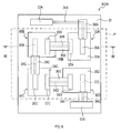
本開示の第4実施形態のガスセンサは、図1のガスセンサ1において、センサ素子3Aを図8及び図9に示すセンサ素子303Aに置き換えたものである。
[4-1.構成]
本開示の第4実施形態のガスセンサは、図1のガスセンサ1において、センサ素子3Aを図8及び図9に示すセンサ素子303Aに置き換えたものである。
センサ素子303Aは、図2及び図3のセンサ素子3Aと同様に、基材31と、複数の測定セル32A,32B,32C,32Dと、複数の端子33A,33Bと、複数の配線34A,34B,34C,34D,34Eと、複数の配線被覆層38A,38B,38C,38D,38Eとを有する。
本実施形態では、各測定セルの参照極は、基材31の表面に配置されている。また、各参照極は、各固体電解質層によって基材31と当接しない表面の少なくとも一部が被覆されている。
第1測定セル32Aを例に説明すると、図9に示すように、第1参照極37Aは、基材31と第1固体電解質層35Aとに当接し、厚み方向に基材31と第1固体電解質層35Aとに挟まれて配置されている。
第1固体電解質層35Aは、第1参照極37Aよりも厚みが大きい。第1参照極37Aは、第2配線34Bとの接続部分と、基材31との当接面以外を除いて、第1固体電解質層35Aに被覆されている。
[4-2.効果]
以上詳述した実施形態によれば、以下の効果が得られる。
(4a)固体電解質層によって参照極によるNOxの活性が抑制できるので、NO2/NO比の変化をより確実に抑制できる。また、固体電解質層が多孔質であることにより、参照極をNOx雰囲気により確実に曝露することができる。
以上詳述した実施形態によれば、以下の効果が得られる。
(4a)固体電解質層によって参照極によるNOxの活性が抑制できるので、NO2/NO比の変化をより確実に抑制できる。また、固体電解質層が多孔質であることにより、参照極をNOx雰囲気により確実に曝露することができる。
[5.第5実施形態]
[5-1.構成]
本開示の第4実施形態のガスセンサは、図1のガスセンサ1において、センサ素子3Aを図11及び図12に示すセンサ素子503Aに置き換えたものである。
[5-1.構成]
本開示の第4実施形態のガスセンサは、図1のガスセンサ1において、センサ素子3Aを図11及び図12に示すセンサ素子503Aに置き換えたものである。
センサ素子503Aは、図8及び図9のセンサ素子303Aと同様に、基材31と、複数の測定セル32A,32B,32C,32Dと、複数の端子33A,33Bと、複数の配線34A,34B,34C,34D,34Eと、複数の配線被覆層38A,38B,38C,38D,38Eとを有する。
本実施形態では、各測定セルの参照極は、セラミックからなり、ガス透過性を有する拡散層50を介して、基材31の表面上に配置されている。拡散層50は、ガス透過性の機能を発揮するように多孔質状に形成されており、センサ素子503Aを構成する基材31のうち、ガス通過領域Pに含まれる部分の表面に積層されている。各参照極は、各固体電解質層によって拡散層50と当接しない表面の少なくとも一部が被覆されている。
第1測定セル32Aを例に説明すると、図12に示すように、第1参照極37Aは、基材31に積層された拡散層50と第1固体電解質層35Aとに当接し、厚み方向に拡散層50と第1固体電解質層35Aとに挟まれて配置されている。
第1参照極37Aは、第2配線34Bとの接続部分と、拡散層50との当接面以外を除いて、第1固体電解質層35Aに被覆されている。
[5-2.効果]
以上詳述した実施形態によれば、以下の効果が得られる。
(5a)固体電解質層によって参照極によるNOxの活性が抑制できるので、NO2/NO比の変化をより確実に抑制できる。また、基材31の表面上に拡散層50を設け、この拡散層50と参照極とを接触させることにより、参照極をNOx雰囲気により確実に曝露することができる。そのため、固体電解質層を多孔質状に形成する必要がない。
以上詳述した実施形態によれば、以下の効果が得られる。
(5a)固体電解質層によって参照極によるNOxの活性が抑制できるので、NO2/NO比の変化をより確実に抑制できる。また、基材31の表面上に拡散層50を設け、この拡散層50と参照極とを接触させることにより、参照極をNOx雰囲気により確実に曝露することができる。そのため、固体電解質層を多孔質状に形成する必要がない。
[6.他の実施形態]
以上、本開示の実施形態について説明したが、本開示は、上記実施形態に限定されることなく、種々の形態を採り得ることは言うまでもない。
以上、本開示の実施形態について説明したが、本開示は、上記実施形態に限定されることなく、種々の形態を採り得ることは言うまでもない。
(6a)上記実施形態のガスセンサ1において、図10に示すセンサ素子403Aのように、ガス通過領域Pに含まれる部分において、被測定ガスGの流路に対して露出した領域(つまり、配線被覆層によって被覆されていない領域)を各配線が有してもよい。また、配線被覆層によって全く被覆されていない配線が存在してもよい。
また、図10のように、各固体電解質層の厚み方向において、各配線被覆層が各固体電解質層と重ならない領域に配置される場合は、各配線被覆層の材質は、絶縁性を有しない、又は高温で絶縁性を維持しないもの(例えば金属酸化物)であってもよい。
(6b)上記実施形態のガスセンサ1のセンサ素子103A,203A,303Aにおいて、各参照極は、被測定ガスGの流路に対して露出した領域(つまり、配線被覆層又は固体電解質層によって被覆されていない領域)を有してもよい。また、配線被覆層又は固体電解質層によって全く被覆されていない参照極が存在してもよい。
(6c)上記実施形態のガスセンサ1において、第1端子33A又は/及び第2端子33Bはガス通過領域P内に配置されてもよい。この場合、第1端子33A又は/及び第2端子33Bは、各端子よりもNOxに対する活性が低い端子被覆層によって被覆されてもよい。
(6d)上記実施形態のガスセンサ1において、ヒータ5は、必ずしもセンサ素子3Aと一体化されなくてもよい。例えば、ヒータ5はセンサキャリア3Bの内部或いは表面、又は触媒ユニット2の内部に配置されてもよい。また、ガスセンサ1は、触媒ユニット2を加熱するための第1ヒータと、センサ素子3Aを加熱するための第2ヒータとを備えてもよい。
(6e)上記実施形態における1つの構成要素が有する機能を複数の構成要素として分散させたり、複数の構成要素が有する機能を1つの構成要素に統合したりしてもよい。また、上記実施形態の構成の一部を省略してもよい。また、上記実施形態の構成の少なくとも一部を、他の上記実施形態の構成に対して付加、置換等してもよい。なお、特許請求の範囲に記載の文言から特定される技術思想に含まれるあらゆる態様が本開示の実施形態である。
1…ガスセンサ、2…触媒ユニット、3…センサユニット、
3A,103A,203A,303A,403A、503A…センサ素子、
3B…センサキャリア、3C…キャップ、5…ヒータ、6…第1配管、7…第2配管、
8…第3配管、31…基材、32A,32B,32C,23D…測定セル、
33A,33B…端子、34A,34B,34C,34D,34E…配線、
35A,35B,35C,35D…固体電解質層、
36A,36B,36C,36D…検知極、
37A,37B,37C,37D…参照極、
38A,38B,38C,38D,38E…配線被覆層、
39A,39B,39C,39D…電極被覆層、40…金属層、50…拡散層。
3A,103A,203A,303A,403A、503A…センサ素子、
3B…センサキャリア、3C…キャップ、5…ヒータ、6…第1配管、7…第2配管、
8…第3配管、31…基材、32A,32B,32C,23D…測定セル、
33A,33B…端子、34A,34B,34C,34D,34E…配線、
35A,35B,35C,35D…固体電解質層、
36A,36B,36C,36D…検知極、
37A,37B,37C,37D…参照極、
38A,38B,38C,38D,38E…配線被覆層、
39A,39B,39C,39D…電極被覆層、40…金属層、50…拡散層。
Claims (7)
- 被測定ガスに含まれるNOx濃度を測定するためのガスセンサであって、
前記被測定ガスに含まれるNOをNO2に変換する触媒ユニットと、
前記触媒ユニットを通過した前記被測定ガス中のNO2を検知するセンサ素子と、
前記触媒ユニットと前記センサ素子とを加熱する少なくとも1つのヒータと、
を備え、
前記センサ素子は、
基材と、
前記基材の表面に配置される複数の測定セル及び複数の端子と、
金属で構成されると共に前記複数の測定セル及び複数の端子を直列に接続する複数の配線と、
前記複数の配線の表面の少なくとも一部を被覆する少なくとも1つの配線被覆層と、
を有し、
前記複数の測定セルは、それぞれ、
固体電解質層と、
前記固体電解質層上に直接又は金属層を介して配置された金属酸化物を主成分とする検知極と、
前記検知極と離間されつつ前記固体電解質層に重ねて配置された金属で構成された参照極と、
を有し、
前記少なくとも1つの配線被覆層は、前記複数の配線よりもNOxに対する活性が低い、ガスセンサ。 - 前記センサ素子は、前記複数の測定セルのうち少なくとも1つの測定セルにおいて、前記参照極の表面の少なくとも一部を被覆する少なくとも1つの電極被覆層をさらに有し、
前記少なくとも1つの電極被覆層は、前記参照極よりもNOxに対する活性が低い、請求項1に記載のガスセンサ。 - 前記少なくとも1つの電極被覆層は、前記少なくとも1つの配線被覆層よりもNOxの透過性が高い、請求項2に記載のガスセンサ。
- 前記複数の測定セルのうち少なくとも1つの測定セルにおいて、前記参照極は、前記基材の表面上に配置されると共に、前記固体電解質層によって前記基材と当接しない表面の少なくとも一部が被覆される、請求項1に記載のガスセンサ。
- 前記複数の測定セルのうち少なくとも1つの測定セルにおいて、前記参照極は、前記基材の表面に積層されたガス透過性を有する拡散層を介して、前記基材の表面上に配置されている、請求項1に記載のガスセンサ。
- 前記複数の測定セルは、前記基材の同一面に配置され、
前記少なくとも1つの配線被覆層は、前記複数の配線のうち、前記触媒ユニットを通過した前記被測定ガスが通過するガス通過領域に含まれる部分を被覆する、請求項1から請求項5のいずれか1項に記載のガスセンサ。 - 前記複数の端子は、前記ガス通過領域の外に配置される、請求項6に記載のガスセンサ。
Applications Claiming Priority (2)
| Application Number | Priority Date | Filing Date | Title |
|---|---|---|---|
| JP2018-127637 | 2018-07-04 | ||
| JP2018127637A JP2021169929A (ja) | 2018-07-04 | 2018-07-04 | ガスセンサ |
Publications (1)
| Publication Number | Publication Date |
|---|---|
| WO2020008808A1 true WO2020008808A1 (ja) | 2020-01-09 |
Family
ID=69060807
Family Applications (1)
| Application Number | Title | Priority Date | Filing Date |
|---|---|---|---|
| PCT/JP2019/022852 Ceased WO2020008808A1 (ja) | 2018-07-04 | 2019-06-10 | ガスセンサ |
Country Status (2)
| Country | Link |
|---|---|
| JP (1) | JP2021169929A (ja) |
| WO (1) | WO2020008808A1 (ja) |
Citations (7)
| Publication number | Priority date | Publication date | Assignee | Title |
|---|---|---|---|---|
| JP2003107039A (ja) * | 2001-09-28 | 2003-04-09 | Matsushita Electric Ind Co Ltd | ガスセンサ |
| JP2009533682A (ja) * | 2006-04-14 | 2009-09-17 | セラマテック・インク | 呼気中の窒素酸化物を測定する装置および方法 |
| JP2010519514A (ja) * | 2007-02-16 | 2010-06-03 | セラマテック・インク | 選択性および検出感度の改善されたNOxセンサー |
| JP2012112651A (ja) * | 2009-03-24 | 2012-06-14 | Sharp Corp | 化学物質検出装置 |
| US20140262835A1 (en) * | 2013-03-15 | 2014-09-18 | The Cleveland Clinic Foundation | Miniaturized gas sensor device and method |
| JP2017515614A (ja) * | 2014-03-07 | 2017-06-15 | スパイロメトリックス・インコーポレイテッド | 呼吸モニタ |
| JP2018096874A (ja) * | 2016-12-14 | 2018-06-21 | 日本特殊陶業株式会社 | 呼気センサ |
-
2018
- 2018-07-04 JP JP2018127637A patent/JP2021169929A/ja active Pending
-
2019
- 2019-06-10 WO PCT/JP2019/022852 patent/WO2020008808A1/ja not_active Ceased
Patent Citations (8)
| Publication number | Priority date | Publication date | Assignee | Title |
|---|---|---|---|---|
| JP2003107039A (ja) * | 2001-09-28 | 2003-04-09 | Matsushita Electric Ind Co Ltd | ガスセンサ |
| JP2009533682A (ja) * | 2006-04-14 | 2009-09-17 | セラマテック・インク | 呼気中の窒素酸化物を測定する装置および方法 |
| JP2010519514A (ja) * | 2007-02-16 | 2010-06-03 | セラマテック・インク | 選択性および検出感度の改善されたNOxセンサー |
| JP2012112651A (ja) * | 2009-03-24 | 2012-06-14 | Sharp Corp | 化学物質検出装置 |
| US20140262835A1 (en) * | 2013-03-15 | 2014-09-18 | The Cleveland Clinic Foundation | Miniaturized gas sensor device and method |
| JP2017515614A (ja) * | 2014-03-07 | 2017-06-15 | スパイロメトリックス・インコーポレイテッド | 呼吸モニタ |
| JP2018096874A (ja) * | 2016-12-14 | 2018-06-21 | 日本特殊陶業株式会社 | 呼気センサ |
| WO2018110117A1 (ja) * | 2016-12-14 | 2018-06-21 | 日本特殊陶業株式会社 | 呼気センサ |
Also Published As
| Publication number | Publication date |
|---|---|
| JP2021169929A (ja) | 2021-10-28 |
Similar Documents
| Publication | Publication Date | Title |
|---|---|---|
| US4647364A (en) | Electrochemical device | |
| US6579435B2 (en) | Gas sensor | |
| US4755274A (en) | Electrochemical sensing element and device incorporating the same | |
| US8414752B2 (en) | Multilayer ceramic NOx gas sensor device | |
| US8038861B2 (en) | Laminated gas sensor element and gas sensor | |
| US6579436B2 (en) | Gas sensor and method of producing the same | |
| US8402813B2 (en) | Sensor element of a gas sensor | |
| US8156789B2 (en) | Gas sensor chip and gas sensor provided therewith | |
| JP2009540334A (ja) | 異種電極を有するアンモニアセンサー | |
| JP3889568B2 (ja) | ガス成分測定装置 | |
| JPWO2000057167A1 (ja) | ガス成分測定装置 | |
| JP2006133039A (ja) | 窒素酸化物センサ | |
| JP2021169929A (ja) | ガスセンサ | |
| WO2019146242A1 (ja) | ガスセンサ | |
| JPH03100450A (ja) | 触媒装置の機能状態検出センサ | |
| JP3395957B2 (ja) | 一酸化炭素検出センサ及びそれを用いた一酸化炭素検出方法 | |
| JPH0760143B2 (ja) | 酸素濃度センサ | |
| US20180252670A1 (en) | Mixed-potential-type sensor | |
| RU2767005C1 (ru) | Высокотемпературная электрохимическая ячейка | |
| JP2003107053A (ja) | ガスセンサのセンサ素子 | |
| GB2627871A (en) | A solid-state oxygen sensor chip | |
| WO2019138710A1 (ja) | ガスセンサ | |
| JP2020112442A (ja) | ガスセンサ | |
| US20080107923A1 (en) | Electrode arrangement for gas sensors | |
| WO2019138712A1 (ja) | ガスセンサ |
Legal Events
| Date | Code | Title | Description |
|---|---|---|---|
| 121 | Ep: the epo has been informed by wipo that ep was designated in this application |
Ref document number: 19830388 Country of ref document: EP Kind code of ref document: A1 |
|
| NENP | Non-entry into the national phase |
Ref country code: DE |
|
| 122 | Ep: pct application non-entry in european phase |
Ref document number: 19830388 Country of ref document: EP Kind code of ref document: A1 |
|
| NENP | Non-entry into the national phase |
Ref country code: JP |