WO2020008712A1 - 測定方法 - Google Patents
測定方法 Download PDFInfo
- Publication number
- WO2020008712A1 WO2020008712A1 PCT/JP2019/017333 JP2019017333W WO2020008712A1 WO 2020008712 A1 WO2020008712 A1 WO 2020008712A1 JP 2019017333 W JP2019017333 W JP 2019017333W WO 2020008712 A1 WO2020008712 A1 WO 2020008712A1
- Authority
- WO
- WIPO (PCT)
- Prior art keywords
- measurement
- offset amount
- sensor
- machine tool
- offset
- Prior art date
- Legal status (The legal status is an assumption and is not a legal conclusion. Google has not performed a legal analysis and makes no representation as to the accuracy of the status listed.)
- Ceased
Links
Images




Classifications
-
- B—PERFORMING OPERATIONS; TRANSPORTING
- B23—MACHINE TOOLS; METAL-WORKING NOT OTHERWISE PROVIDED FOR
- B23Q—DETAILS, COMPONENTS, OR ACCESSORIES FOR MACHINE TOOLS, e.g. ARRANGEMENTS FOR COPYING OR CONTROLLING; MACHINE TOOLS IN GENERAL CHARACTERISED BY THE CONSTRUCTION OF PARTICULAR DETAILS OR COMPONENTS; COMBINATIONS OR ASSOCIATIONS OF METAL-WORKING MACHINES, NOT DIRECTED TO A PARTICULAR RESULT
- B23Q17/00—Arrangements for observing, indicating or measuring on machine tools
-
- B—PERFORMING OPERATIONS; TRANSPORTING
- B23—MACHINE TOOLS; METAL-WORKING NOT OTHERWISE PROVIDED FOR
- B23Q—DETAILS, COMPONENTS, OR ACCESSORIES FOR MACHINE TOOLS, e.g. ARRANGEMENTS FOR COPYING OR CONTROLLING; MACHINE TOOLS IN GENERAL CHARACTERISED BY THE CONSTRUCTION OF PARTICULAR DETAILS OR COMPONENTS; COMBINATIONS OR ASSOCIATIONS OF METAL-WORKING MACHINES, NOT DIRECTED TO A PARTICULAR RESULT
- B23Q17/00—Arrangements for observing, indicating or measuring on machine tools
- B23Q17/20—Arrangements for observing, indicating or measuring on machine tools for indicating or measuring workpiece characteristics, e.g. contour, dimension, hardness
-
- G—PHYSICS
- G01—MEASURING; TESTING
- G01B—MEASURING LENGTH, THICKNESS OR SIMILAR LINEAR DIMENSIONS; MEASURING ANGLES; MEASURING AREAS; MEASURING IRREGULARITIES OF SURFACES OR CONTOURS
- G01B11/00—Measuring arrangements characterised by the use of optical techniques
-
- G—PHYSICS
- G01—MEASURING; TESTING
- G01B—MEASURING LENGTH, THICKNESS OR SIMILAR LINEAR DIMENSIONS; MEASURING ANGLES; MEASURING AREAS; MEASURING IRREGULARITIES OF SURFACES OR CONTOURS
- G01B21/00—Measuring arrangements or details thereof, where the measuring technique is not covered by the other groups of this subclass, unspecified or not relevant
-
- G—PHYSICS
- G01—MEASURING; TESTING
- G01B—MEASURING LENGTH, THICKNESS OR SIMILAR LINEAR DIMENSIONS; MEASURING ANGLES; MEASURING AREAS; MEASURING IRREGULARITIES OF SURFACES OR CONTOURS
- G01B21/00—Measuring arrangements or details thereof, where the measuring technique is not covered by the other groups of this subclass, unspecified or not relevant
- G01B21/22—Measuring arrangements or details thereof, where the measuring technique is not covered by the other groups of this subclass, unspecified or not relevant for measuring angles or tapers; for testing the alignment of axes
-
- G—PHYSICS
- G01—MEASURING; TESTING
- G01B—MEASURING LENGTH, THICKNESS OR SIMILAR LINEAR DIMENSIONS; MEASURING ANGLES; MEASURING AREAS; MEASURING IRREGULARITIES OF SURFACES OR CONTOURS
- G01B5/00—Measuring arrangements characterised by the use of mechanical techniques
Definitions
- the present invention relates to a method for measuring an object to be measured, and particularly to a method for measuring an object to be measured on a machine tool.
- a sensor can be attached to a main shaft of a machine tool, and an object to be measured (workpiece) can be measured while being attached to the machine tool.
- an object to be measured workpiece
- a three-dimensional offset amount of the sensor attached to the main shaft is acquired using a reference sphere or the like, and the workpiece is measured using the acquired offset amount.
- the present invention has been made in view of the above problems, and in measuring an object to be measured on a machine tool, measurement of the object to be measured can be started immediately after machining by omitting temperature equalization, thereby improving work efficiency. It is an object of the present invention to provide a measuring method capable of effectively suppressing a decrease in the measurement.
- a method for measuring an object to be measured on the machine tool using a sensor attached to the machine tool The step of acquiring the offset amount of the attached sensor is performed a plurality of times at a predetermined time, and the measurement result is corrected based on the offset amounts acquired in the plurality of steps.
- FIG. 5 is a flowchart illustrating a measurement method according to one embodiment of the present invention. It is a perspective view which shows typically an example of the method of acquiring the offset amount of a sensor.
- 9 is a time chart showing a measuring method according to another embodiment of the present invention. 9 is a time chart showing a measuring method according to another embodiment of the present invention.
- 4B is a graph showing an example of calculating an expected offset amount at the time of measurement by interpolating the offset amount acquired at the timing shown in FIG. 4A. It is a graph which shows the other example which determines the correlation of time and an expected offset amount by interpolating the acquired offset amount.
- FIG. 1 is a flowchart showing a measuring method according to one embodiment of the present invention.
- the measuring method according to the present embodiment is a method of measuring an object to be measured on a machine tool using a sensor attached to the machine tool. A sensor attached to the machine tool without removing the workpiece (measured object) processed by the machine tool from the machine tool and attaching it to the machine tool without attaching it to another measuring device. Can be measured.
- the local coordinates are coordinates relative to the sensor.
- World coordinates are the absolute coordinates of the space in which the machine tool on which the sensor is mounted exists.
- the machine tool after processing is at a high temperature, and it takes time for the temperature to be measured to measure the offset amount of the sensor attached to the machine tool with sufficient accuracy. Since a long time is required for this temperature smoothing, a long idle period occurs until the measurement starts, and the working efficiency is reduced.
- the step of obtaining the offset amount of the attached sensor is performed a plurality of times at a predetermined time, and the measurement result is corrected based on the offset amounts obtained in the plurality of steps.
- the sensor offset amount means a three-dimensional offset amount, that is, an offset amount related to the position and inclination (angle) of the sensor.
- the measurement result here includes not only the final measurement result but also data deformation or manipulation that affects the final measurement result.
- the step of acquiring the offset amount and the measurement of the object to be measured are alternately performed as described below. That is, the first offset amount acquisition step 1, the first measurement 1, the second offset amount acquisition step 2, the second measurement 2, the third offset amount acquisition step 3, and the third measurement 3 are sequentially performed. .
- correction is performed using the offset amount acquired in at least the first offset amount acquisition step 1, and the coordinate is converted into world coordinates.
- correction is performed using at least the offset amount acquired in the second offset amount acquisition step 2 to convert the offset into world coordinates.
- correction is performed using at least the offset amount acquired in the third offset amount acquiring step 3, and the data is converted into world coordinates.
- correction using the offset amounts acquired in the first and second offset amount acquisition steps 1 and 2 can be performed to convert the offset into world coordinates
- correction using the offset amounts obtained in the first to third offset amount obtaining steps 1 to 3 can be performed to convert the coordinates to world coordinates.
- the step of acquiring the offset amount of the sensor is performed a plurality of times, and the measurement result is corrected based on the offset amounts acquired in the plurality of steps.
- the measurement of the object to be measured can be started immediately after processing, and a decrease in work efficiency can be effectively suppressed.
- the timing for performing the step of acquiring the sensor offset amount is preferably determined based on, for example, a measurement value of a temperature sensor provided in the machine tool. There is a possibility that the shift amount of the sensor also changes according to the temperature change until the machine tool that has become hot during processing returns to the steady temperature. Therefore, by determining the timing for performing the step of acquiring the offset amount of the sensor based on the measurement value of the temperature sensor, it is possible to realize the optimal acquisition of the offset amount according to the temperature change of the machine tool.
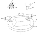
- FIG. 2 is a perspective view schematically showing an example of a method for obtaining the offset amount of the sensor.
- arrows indicate the six degrees of freedom in which the object moves: the X-axis direction, the Y-axis direction, and the Z-axis direction, and the directions A, B, and C, which are rotation directions around each axis.
- the measurement of the workpiece W is started immediately without waiting for the machine tool that has become hot after processing to equilibrate in temperature.
- the step of acquiring the offset amount of the attached sensor 30 is performed a plurality of times at a predetermined time, and the measurement result is corrected based on the offset amounts acquired in the plurality of steps.
- the tool spindle 10 to which the sensor 30 is attached is movable in any direction of the X, Y, and Z axes, and is rotatable around the axis of the tool spindle 10. For example, if the axis extends in the Z-axis direction, the sensor 30 can rotate in the C-axis direction around the Z-axis.
- the processing table 20 to which the workpiece W is attached is rotatable in the C-axis direction around the Z-axis.
- FIG. 2 shows a process of obtaining the offset amount using the reference sphere 40A or 40B whose shape and size are known.
- the reference spheres 40A and 40B have a structure in which a shaft portion 44 of a predetermined length extends from the base portion 42, and a sphere portion 46 is attached to the tip.
- the reference sphere 40A is mounted on the workpiece W, and the reference sphere 40B is mounted on the processing table 20.
- the step of acquiring the offset amount of the attached sensor 30 is performed a plurality of times at a predetermined timing, but the reference sphere used according to the timing is changed among the two reference spheres of the reference spheres 40A and 40B. It is possible. A detailed description of this will be described later.
- the offset amount is acquired in the following procedure.
- the tool spindle 10 is driven to relatively move the sensor 30 and the reference ball 40A (or 40B), and the sensor 30 measures the reference ball 40A (or 40B) before and after the movement.
- the sensor 30 can calculate the offset amount by measuring the reference sphere 40A (or 40B) a plurality of times from different directions. For example, by measuring the reference sphere 40A (or 40B), the coordinates of the center position of the sphere 46 can be calculated, and the offset direction and the offset amount can be obtained from the difference between the coordinates calculated from each measurement.
- Examples of the sensor 30 include a laser displacement sensor, an optical cutting sensor, a phase shift sensor, and an image sensor.
- the measurement is performed by relatively moving the sensor 30 and the reference sphere 40A a required number of times based on the type of the sensor 30 and the direction in which the offset amount needs to be acquired among the six degrees of freedom.
- a known arbitrary method can be adopted as a method for acquiring the offset amount using the reference sphere.
- the machining table 20 may be driven instead of the tool spindle 10 to relatively move the sensor 30 and the reference sphere 40A, or both the tool spindle 10 and the machining table 20 may be driven.
- the sensor 30 and the reference sphere 40A can be relatively moved.
- the sensor 30 may be attached to a member that does not move.
- the image sensor may be fixed at a predetermined position above the processing table 20 and the workpiece W attached to the processing table 20 may be measured. In this case, by rotating the processing table 20, the sensor 30 and the reference sphere 40A can be relatively moved. Further, the offset amount can be obtained using a predetermined portion (for example, a protrusion or a hole) of the measured object W itself without using the reference sphere.
- FIG. 3 is a time chart showing a measuring method according to another embodiment of the present invention.
- a step of acquiring the offset amount is performed at the start of the measurement, during the measurement period, and at the end of the measurement.
- the number of steps of acquiring the offset amount performed during the measurement period is shown in FIG. 3 as two steps, the number of steps is not limited to this, and the number of steps is not limited to this. Any number of times can be set accordingly.
- the step of acquiring the offset amount is performed at the start of measurement, during the measurement period, and at the end of measurement, so that a more accurate expected offset amount can be calculated, and a more accurate measurement result can be obtained. Can be expected.
- the item for acquiring the offset amount in the step at the start of the measurement and the item for acquiring the offset amount in the subsequent steps can be made different.
- offset amounts are acquired for six degrees of freedom in the X-axis, Y-axis, Z-axis, A-axis, B-axis, and C-axis directions for a sensor attached to a machine tool.
- the following can be considered.
- the length of the shaft portion 44 must be set. It is preferable to take a long time and arrange the ball portion 46 at a high position.
- the tool spindle 10 and the sensor 30 are moved to measure the workpiece W, there is a possibility that the tool spindle 10 and the sensor 30 will interfere with the reference sphere 40A.
- the offset amount of the sensor 30 in an arbitrary direction is acquired using the reference sphere 40A mounted on the workpiece W.
- the sensor 30 is limited by using a reference sphere installed in a place where the possibility of interference with the tool spindle 10 and the sensor 30 is low, for example, a reference sphere 40B mounted on the processing table 20.
- the offset amount may be obtained by measuring the protrusion, the hole, or the like of the measured object W with the sensor 30 without using the reference sphere. This means that the item for acquiring the offset amount is different between the step at the start of measurement and the subsequent steps, and that the method of measurement is different between the step at the start of measurement and the subsequent steps. .
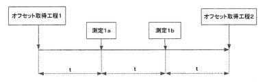
- FIG. 4A is a time chart illustrating a measuring method according to another embodiment of the present invention.
- FIG. 4B is a graph showing an example of calculating an expected offset amount at the time of measurement by interpolating the offset amount acquired at the timing shown in FIG. 4A.
- the first measurement 1a is performed when the time t has elapsed from the first offset amount acquisition step 1.
- the second measurement 1b is performed when a time t has elapsed from the first measurement 1a.
- the second offset amount acquisition step 2 is performed when the time t has elapsed from the second measurement 1b.
- the graph in FIG. 4B shows the correlation between the time and the expected offset amount when linearly interpolating between the first offset amount obtaining step 1 and the second offset amount obtaining step 2.
- the offset amount acquired in the first offset amount acquiring step 1 is A1
- the second offset amount acquiring step 2 is A2
- the amount can be calculated as follows.
- the offset amount of the first measurement 1a 2/3 ⁇ A1 + / ⁇ A2
- the offset amount of the second measurement 1b 1/3 ⁇ A1 + 2/3 ⁇ A2
- FIG. 5 is a graph showing another example of determining the correlation between the time and the expected offset amount by interpolating the acquired offset amount.
- FIG. 5 shows a case where an approximate curve showing the correlation between the time and the expected offset amount is formed based on the four acquired offset amounts.
- any known method such as the least squares method can be used.
- an arbitrary curve such as a parabolic curve, a Bezier curve or other nth-order curve, a circle, an ellipse, a hyperbola, or a curve using a trigonometric function can be used.
- the correlation between the time and the expected offset amount is determined, and when the measurement result is corrected based on the correlation, the measured value is corrected in the following manner. Can be. For example, after the measurement is completed, the correlation can be determined using all the acquired offset amounts, and the measured values can be corrected collectively. On the other hand, it is also possible to calculate the offset amount at each measurement and correct the measured value each time.
- the estimation of the offset amount at each measurement can be performed using the latest acquired offset amount, or all the offset amounts acquired so far at the time of measurement, or a part of the offset amount acquired so far can be obtained. It can also be used for estimation. Further, it is also possible to determine the correlation using the offset amount acquired up to a certain point in time, extend the correlation (an approximate straight line or an approximate curve) with time, and calculate the expected offset amount.
- the correlation between the time and the expected offset amount is determined, and the measurement result is corrected based on the correlation, thereby efficiently and accurately calculating the expected offset amount.
- accurate measurement of the device under test can be expected.
Landscapes
- Physics & Mathematics (AREA)
- General Physics & Mathematics (AREA)
- Engineering & Computer Science (AREA)
- Mechanical Engineering (AREA)
- A Measuring Device Byusing Mechanical Method (AREA)
- Length Measuring Devices By Optical Means (AREA)
- Length Measuring Devices With Unspecified Measuring Means (AREA)
- Machine Tool Sensing Apparatuses (AREA)
- Numerical Control (AREA)
Abstract
工作機に取り付けられたセンサを用いて工作機上の被測定物を測定する方法であって、取り付けられたセンサのオフセット量を取得する工程を所定の時機に複数回行い、複数回の工程で取得されたオフセット量に基づいて測定結果を補正する測定方法を提供する。これにより、工作機械上での被測定物の測定において、温度ならしを省略して、加工後速やかに被測定物の測定を開始でき、作業効率の低下を効果的に抑制できる。
Description
本発明は、被測定物を測定する方法、特に、工作機上の被測定物を測定する方法に関する。
工作機械により加工された工作物を測定するには、工作物を工作機械から取り外して、別の測定装置に取り付けて測定を行うのが一般的である。その場合、工作物の取り外し、取り付けのために多くの時間と工数がかかり、また測定装置への取り付け時において、取り付け誤差が生じる可能性もある。このような問題に対処するため、工作物が工作機械に取り付けられた状態で、工作機械内で工作物の測定を行う測定方法が提案されている(例えば、特許文献1参照)。
特許文献1に記載の測定方法では、工作機械の主軸にセンサを取り付けて、工作機械に取り付けられたままの被測定物(工作物)を測定することができる。この場合、測定を開始する前に、基準球等を用いて、主軸に取り付けられたセンサの3次元のオフセット量を取得し、取得されたオフセット量を用いて工作物の測定を行う。
しかし、加工後の工作機械は高温であり、取り付けられたセンサの3次元オフセットを十分な精度で計測するには、温度的に平衡させる、所謂温度ならしのための時間を要する。この温度ならしには長時間を要するため、作業効率が低下する。
本発明は、上記問題に鑑みてなされたものであり、工作機械上での被測定物の測定において、温度ならしを省略して、加工後速やかに被測定物の測定を開始でき、作業効率の低下を効果的に抑制できる測定方法を提供することを目的とする。
上記課題を解決するために、本発明の1つの実施態様に係る測定方法では、
工作機に取り付けられたセンサを用いて前記工作機上の被測定物を測定する方法であって、
取り付けられた前記センサのオフセット量を取得する工程を所定の時機に複数回行い、該複数回の工程で取得された前記オフセット量に基づいて測定結果を補正する。
工作機に取り付けられたセンサを用いて前記工作機上の被測定物を測定する方法であって、
取り付けられた前記センサのオフセット量を取得する工程を所定の時機に複数回行い、該複数回の工程で取得された前記オフセット量に基づいて測定結果を補正する。
上記の実施態様によれば、温度ならしを省略して、加工後速やかに被測定物の測定を開始でき、作業効率の低下を効果的に抑制できる測定方法を提供することができる。
以下、図面を参照しながら、本発明を実施するための実施形態を説明する。以下に説明する実施形態は、本発明の技術思想を具体化するためのものであって、特定的な記載がない限り、本発明を以下のものに限定しない。
後述の実施形態や実施例では、前述と共通の事柄についての記述を省略し、異なる点についてのみ説明する。特に、同様の構成による同様の作用効果については、各実施形態、実施例ごとには逐次言及しないものとする。各図面が示す部材の大きさや位置関係等は、説明を明確にするため、誇張して示している場合もある。
(1つの実施形態に係る測定方法)
始めに、図1を参照しながら、本発明に係る測定方法の概要を説明する。図1は、本発明の1つの実施形態に係る測定方法を示すフローチャートである。
本実施形態に係る測定方法は、工作機に取り付けられたセンサを用いて、工作機上の被測定物を測定する方法である。工作機で加工された工作物(被測定物)を、工作機械から取り外して、他の測定装置に取り付けることなく、そのまま、工作機械に被測定物を取り付けたまま、工作機に取り付けられたセンサを用いて測定することができる。
始めに、図1を参照しながら、本発明に係る測定方法の概要を説明する。図1は、本発明の1つの実施形態に係る測定方法を示すフローチャートである。
本実施形態に係る測定方法は、工作機に取り付けられたセンサを用いて、工作機上の被測定物を測定する方法である。工作機で加工された工作物(被測定物)を、工作機械から取り外して、他の測定装置に取り付けることなく、そのまま、工作機械に被測定物を取り付けたまま、工作機に取り付けられたセンサを用いて測定することができる。
被測定物の測定には、センサにより取得したローカル座標をワールド座標に変換する必要がある。ローカル座標とは、センサを基準とした相対的な座標である。ワールド座標は、センサが取り付けられた工作機械が存在する空間の絶対的な座標である。センサを工作機械の所定の部材、例えば主軸に取り付けるごとに、センサの主軸に対する相対的な位置、姿勢は一定ではない。
よって、通常、測定開始前に、センサの取り付けの基準位置からのオフセット量を測定して、センサが測定したローカル座標の測定値をワールド座標に変換するとき、オフセット分を補正する必要がある。このことを、キャリブレーションとも称する。
一方、加工後の工作機械は高温であり、工作機械に取り付けられたセンサのオフセット量を十分な精度で計測するには、温度ならしのための時間を要する。この温度ならしには長時間を要するため、測定開始まで長いアイドル期間が生じて作業効率が低下する。
一方、加工後の工作機械は高温であり、工作機械に取り付けられたセンサのオフセット量を十分な精度で計測するには、温度ならしのための時間を要する。この温度ならしには長時間を要するため、測定開始まで長いアイドル期間が生じて作業効率が低下する。
そこで、本実施形態においては、取り付けられたセンサのオフセット量を取得する工程を所定の時機に複数回行い、複数回の工程で取得されたオフセット量に基づいて測定結果を補正するようになっている。ここでいうセンサのオフセット量とは、3次元のオフセット量、つまりセンサの位置及び傾き(角度)に関するオフセット量を意味する。具体的には、図2に示すような、6つの自由度:X軸方向、Y軸方向及びZ軸方向、並びに各軸周りの回転方向であるA方向、B方向及びC方向に関するオフセット量である。
また、ここでいう測定結果とは、最終的な測定結果のみではなく、最終測定結果に影響を及ぼすデータの変形または操作を含んでいる。
また、ここでいう測定結果とは、最終的な測定結果のみではなく、最終測定結果に影響を及ぼすデータの変形または操作を含んでいる。
図1の例では、機械加工終了後、下記のように、オフセット量を取得する工程と、被測定物の測定を交互に行っている。つまり、1回目のオフセット量取得工程1、1回目の測定1、2回目のオフセット量取得工程2、2回目の測定2、3回目のオフセット量取得工程3、及び3回目の測定3を順に行う。
このとき、1回目の測定1では、少なくとも1回目のオフセット量取得工程1で取得したオフセット量を用いた補正を行って、ワールド座標に変換する。同様に、2回目の測定2では、少なくとも2回目のオフセット量取得工程2で取得したオフセット量を用いた補正を行って、ワールド座標に変換する。3回目の測定3では、少なくとも3回目のオフセット量取得工程3で取得したオフセット量を用いた補正を行って、ワールド座標に変換する。
更に、2回目の測定2では、1回目及び2回目のオフセット量取得工程1、2で取得したオフセット量を用いた補正を行って、ワールド座標に変換することもできるし、3回目の測定では、1回から3回目までのオフセット量取得工程1~3で取得したオフセット量を用いた補正を行って、ワールド座標に変換することもできる。
更に、2回目の測定2では、1回目及び2回目のオフセット量取得工程1、2で取得したオフセット量を用いた補正を行って、ワールド座標に変換することもできるし、3回目の測定では、1回から3回目までのオフセット量取得工程1~3で取得したオフセット量を用いた補正を行って、ワールド座標に変換することもできる。
以上のように、本実施形態では、センサのオフセット量を取得する工程を複数回行い、複数回の工程で取得されたオフセット量に基づいて測定結果を補正するので、温度ならしを省略して、加工後速やかに被測定物の測定を開始でき、作業効率の低下を効果的に抑制できる。
センサのオフセット量を取得する工程を行う時機については、例えば、工作機に備えられた温度センサの測定値に基づいて定めることが好ましい。加工で高温になった工作機械が定常温度に戻るまでの温度変化に応じて、センサのシフト量も変化する可能性がある。
よって、温度センサの測定値に基づいてセンサのオフセット量を取得する工程を行う時機を定めることにより、工作機械の温度変化に応じた最適な時機におけるオフセット量の取得が実現できる。
よって、温度センサの測定値に基づいてセンサのオフセット量を取得する工程を行う時機を定めることにより、工作機械の温度変化に応じた最適な時機におけるオフセット量の取得が実現できる。
(オフセット量を取得する方法)
次に、図2を参照しながら、センサのオフセット量を取得する方法の一例を説明する。図2は、センサのオフセット量を取得する方法の一例を模式的に示す斜視図である。なお、図2に、物体が移動する6つの自由度:X軸方向、Y軸方向及びZ軸方向、並びに各軸周りの回転方向であるA方向、B方向及びC方向を矢印で示す。
次に、図2を参照しながら、センサのオフセット量を取得する方法の一例を説明する。図2は、センサのオフセット量を取得する方法の一例を模式的に示す斜視図である。なお、図2に、物体が移動する6つの自由度:X軸方向、Y軸方向及びZ軸方向、並びに各軸周りの回転方向であるA方向、B方向及びC方向を矢印で示す。
図2に示す例では、工作機の工具主軸10に取り付けられたセンサ30を用いて、工作機の加工テーブル20上に取り付けられた被測定物Wを測定する場合を示す。つまり、工具主軸10に工具を取り付けて工作物を加工後、工具主軸10から工具を取り外して、代わりに、工具ホルダを介してセンサ30を取り付けた場合に該当する。ここでは、非接触式のセンサ30を取り付けた場合を示すが、これに限られるものではなく、接触式のセンサを用いた場合もあり得る。
上記のように、加工後、高温になった工作機械が温度的に平衡になるのを待たず、速やかに被測定物Wの測定を開始する。このとき、取り付けられたセンサ30のオフセット量を取得する工程を所定の時機に複数回行い、この複数回の工程で取得されたオフセット量に基づいて測定結果を補正する。
センサ30が取り付けられた工具主軸10は、X、Y、Z軸の任意の方向に移動可能であり、工具主軸10の軸周りを回転可能になっている。例えば、軸がZ軸方向に延びている場合、センサ30は、Z軸周りのC軸方向に回転可能である。被測定物Wが取り付けられた加工テーブル20は、Z軸周りのC軸方向に回転可能になっている。
図2では、形状及び寸法が既知の基準球40Aまたは40Bを用いて、オフセット量を取得する工程を示す。基準球40A、40Bは、ベース部42から所定の長さの軸部44が伸び、その先端に球部46が取り付けられた構造を有する。基準球40Aが被測定物Wに上に取り付けられ、基準球40Bが加工テーブル20の上に取り付けられている。
実際には、基準球40Aまたは40Bのどちらか一方のみが取り付けられている場合もあり得るし、両方が取り付けられている場合もあり得る。本測定方法では、取り付けられたセンサ30のオフセット量を取得する工程を所定の時機に複数回行うが、基準球40A、40Bの2つの基準球のうち、時機に応じて用いる基準球を異ならせることもあり得る。なお、これに関する詳細な説明は後述する。
センサのオフセット量を取得する工程では、以下の手順でオフセット量を取得する。例えば、工具主軸10を駆動して、センサ30及び基準球40A(または40B)を相対的に移動させ、移動前後で、センサ30により基準球40A(または40B)を測定する。このようにして、センサ30により、異なる方向から基準球40A(または40B)を複数回測定することにより、オフセット量を算出することができる。例えば、基準球40A(または40B)の測定により、球部46の中心位置の座標を算出し、各測定から算出した座標の差から、オフセット方向及びオフセット量を取得することができる。
センサ30としては、レーザ式変位センサ、光学切断式センサ、位相シフト式センサ、画像センサ等を例示することができる。センサ30の種類、及び6つの自由度のうちオフセット量を取得する必要がある方向に基づいて、必要な回数だけ、センサ30及び基準球40Aを相対的に移動させて測定を行う。基準球を用いたオフセット量の取得方法については、既知の任意の方法を採用することができる。
なお、オフセット量の取得に当たり、工具主軸10ではなく、加工テーブル20を駆動して、センサ30及び基準球40Aを相対的に移動させることもできるし、工具主軸10及び加工テーブル20の両方を駆動して、センサ30及び基準球40Aを相対的に移動させることもできる。
センサ30が工具主軸10に取り付けられた場合だけでなく、センサ30が工作機械のその他の主軸、テーブル等に取り付けられる場合もあり得る。更に、センサ30を移動しない部材に取り付けることもあり得る。例えば、画像センサを加工テーブル20の上方の所定位置に固定して、加工テーブル20に取り付けられた被測定物Wを測定する場合もあり得る。この場合、加工テーブル20を回転させることにより、センサ30及び基準球40Aを相対的に移動させることができる。更に、基準球を用いずに、被測定物W自体の所定箇所(例えば、突起部や穴部)を用いて、オフセット量を取得することもできる。
(その他の実施形態に係る測定方法)
次に、図3を参照しながら、本発明のその他の実施形態に係る測定方法の説明を行う。図3は、本発明のその他の実施形態に係る測定方法を示すタイムチャートである。
図3に示す測定方法においては、測定開始時、測定期間中、及び測定終了時にオフセット量を取得する工程を行うようになっている。なお、測定期間中に実施するオフセット量を取得する工程の回数については、図3では2回の工程が示されているが、これに限られるものではなく、測定内容や工作機械の状態等に応じて、任意の回数を設定することができる。
次に、図3を参照しながら、本発明のその他の実施形態に係る測定方法の説明を行う。図3は、本発明のその他の実施形態に係る測定方法を示すタイムチャートである。
図3に示す測定方法においては、測定開始時、測定期間中、及び測定終了時にオフセット量を取得する工程を行うようになっている。なお、測定期間中に実施するオフセット量を取得する工程の回数については、図3では2回の工程が示されているが、これに限られるものではなく、測定内容や工作機械の状態等に応じて、任意の回数を設定することができる。
以上のように、本実施形態では、オフセット量を取得する工程を、測定開始時、測定期間中及び測定終了時に行うので、より精度の高い予想オフセット量を算出でき、より精度の高い測定結果が期待できる。
更に、測定開始時の工程でオフセット量を取得する項目と、それ以降の工程でオフセット量を取得する項目を異ならせることもできる。
例えば、測定開始時には、工作機械に取り付けられたセンサについて、X軸、Y軸、Z軸、A軸、B軸及びC軸方向の6自由度について、オフセット量を取得するが、それ以降の工程においては、主に温度変化によるオフセット量の変化を捉えるため、X軸、Y軸及びZ軸方向の3自由度について、オフセット量を取得することが考えられる。
例えば、測定開始時には、工作機械に取り付けられたセンサについて、X軸、Y軸、Z軸、A軸、B軸及びC軸方向の6自由度について、オフセット量を取得するが、それ以降の工程においては、主に温度変化によるオフセット量の変化を捉えるため、X軸、Y軸及びZ軸方向の3自由度について、オフセット量を取得することが考えられる。
測定開始時の工程でオフセット量を取得する項目と、それ以降の工程でオフセット量を取得する項目を異ならせるその他の例として、以下が考えられる。
図2に示すように、被測定物W上に取り付けられた基準球40Aを用いてオフセット量を取得する場合、任意の方向のオフセット量を確実に取得するには、軸部44の長さを長く取って、球部46を高い位置に配置することが好ましい。一方、その場合、被測定物Wを測定するために、工具主軸10及びセンサ30を移動させたとき、基準球40Aと干渉する可能性がある。
図2に示すように、被測定物W上に取り付けられた基準球40Aを用いてオフセット量を取得する場合、任意の方向のオフセット量を確実に取得するには、軸部44の長さを長く取って、球部46を高い位置に配置することが好ましい。一方、その場合、被測定物Wを測定するために、工具主軸10及びセンサ30を移動させたとき、基準球40Aと干渉する可能性がある。
これに対処するため、例えば、以下の手順が考えられる。測定開始時には、被測定物W上に取り付けられた基準球40Aを用いて、センサ30の任意の方向のオフセット量を取得する。それ以降の工程では、工具主軸10やセンサ30との干渉の可能性が低い場所に設置された基準球、例えば、加工テーブル20上に取り付けられた基準球40Bを用いて、センサ30の限定された方向のオフセット量を取得する。更に、2回目降の工程では、基準球を用いずに、センサ30で被測定物Wの突起部や穴部等を測定することにより、オフセット量を取得することも考えられる。このことは、測定開始時の工程及びそれ以降の工程で、オフセット量を取得する項目を異ならせるとともに、測定開始時の工程及びそれ以降の工程で、測定のやり方を異ならせると言うこともできる。
以上のように、測定開始時の工程でオフセット量を取得する項目と、それ以降の工程でオフセット量を取得する項目とを異ならせることにより、必要な測定精度に応じた効率的な測定を実現できる。
(取得したオフセット量の補間)
次に、図4A及び図4Bを参照しながら、取得されたオフセット量を補間することにより、計測時点での予想オフセット量を算出する例を説明する。図4Aは、本発明のその他の実施形態に係る測定方法を示すタイムチャートである。図4Bは、図4Aに示すタイミングで取得されたオフセット量を補間することにより、計測時点での予想オフセット量を算出する例を示すグラフである。
次に、図4A及び図4Bを参照しながら、取得されたオフセット量を補間することにより、計測時点での予想オフセット量を算出する例を説明する。図4Aは、本発明のその他の実施形態に係る測定方法を示すタイムチャートである。図4Bは、図4Aに示すタイミングで取得されたオフセット量を補間することにより、計測時点での予想オフセット量を算出する例を示すグラフである。
図4Aのタイムチャートでは、1回目のオフセット量取得工程1及び2回目のオフセット量取得工程2の間に、被測定物Wを2回測定した場合を示す。2回の測定のうち、1回目の測定1aは、1回目のオフセット量取得工程1から時間tが経過した時点で行われる。2回目の測定1bは、1回目の測定1aから時間tが経過した時点で行われる。そして、2回目のオフセット量取得工程2は、2回目の測定1bから時間tが経過した時点で行われる。
図4Bのグラフは、1回目のオフセット量取得工程1及び2回目のオフセット量取得工程2の間を線形に補間した場合の時間及び予想オフセット量の相関を示す。1回目のオフセット量取得工程1で取得したオフセット量をA1、2回目のオフセット量取得工程2取得したオフセット量をA2とすれば、1回目の測定1a及び2回目の測定1bのタイミングにおける予想オフセット量は、以下のように算出できる。
- 1回目の測定1aのオフセット量=2/3×A1+1/3×A2
- 2回目の測定1bのオフセット量=1/3×A1+2/3×A2
- 1回目の測定1aのオフセット量=2/3×A1+1/3×A2
- 2回目の測定1bのオフセット量=1/3×A1+2/3×A2
以上のように、複数のオフセット量を補間することにより、効率的に適確に予想オフセット量を算出することができる。特に、図4Bに示す例のように、測定前及び測定後に取得したオフセット量を補間することにより、より正確な予想オフセット量を得ることが期待できる。
(時間及び予想オフセット量の相関)
次に、図5を参照しながら、取得された複数のオフセット量に基づいて、時間及び予想オフセット量の相関を定め、この相関に基づいて測定結果を補正するその他の例を説明する。図5は、取得されたオフセット量を補間して、時間及び予想オフセット量の相関を定めるその他の例を示すグラフである。
次に、図5を参照しながら、取得された複数のオフセット量に基づいて、時間及び予想オフセット量の相関を定め、この相関に基づいて測定結果を補正するその他の例を説明する。図5は、取得されたオフセット量を補間して、時間及び予想オフセット量の相関を定めるその他の例を示すグラフである。
図5では、取得された4つのオフセット量に基づいて、時間及び予想オフセット量の相関を示す近似曲線を形成した場合を示す。近似曲線を形成するには、最小二乗法をはじめとする、既知の任意の手法を用いることができる。近似曲線として、放物線、ベジエ曲線をはじめとするn次曲線、円、楕円、双曲線、三角関数による曲線等の任意の曲線を用いることができる。
以上のように、取得された複数のオフセット量に基づいて、時間及び予想オフセット量の相関を定め、この相関に基づいて測定結果を補正する場合、以下のようなやり方で測定値を補正することができる。
例えば、測定終了後に、取得した全てのオフセット量を用いて相関を定めて、まとめて各測定値を補正することができる。一方、各測定時におけるオフセット量を算出して、その都度測定値を補正することもできる。
例えば、測定終了後に、取得した全てのオフセット量を用いて相関を定めて、まとめて各測定値を補正することができる。一方、各測定時におけるオフセット量を算出して、その都度測定値を補正することもできる。
各測定時におけるオフセット量の推定は、直近に取得したオフセット量を用いて推定をすることもできるし、測定時にそれまでに取得した全てオフセット量、またはそれまでに取得したオフセット量の一部を用いて推定をすることもできる。
更に、ある時点までに取得したオフセット量を用いて相関を定め、その相関(近似直線または近似曲線)を時間的に延長させて、予想オフセット量を算出することもできる。
更に、ある時点までに取得したオフセット量を用いて相関を定め、その相関(近似直線または近似曲線)を時間的に延長させて、予想オフセット量を算出することもできる。
以上のように、取得された複数のオフセット量に基づいて、時間及び予想オフセット量の相関を定め、この相関に基づいて測定結果を補正することにより、効率的に適確に予想オフセット量を算出して、正確な被測定物の測定が期待できる。
本発明の実施の形態、実施の態様を説明したが、開示内容は構成の細部において変化してもよく、実施の形態、実施の態様における要素の組合せや順序の変化等は請求された本発明の範囲および思想を逸脱することなく実現し得るものである。
10 工具主軸
20 加工テーブル
30 センサ
40A、B 基準球
W 被測定物
20 加工テーブル
30 センサ
40A、B 基準球
W 被測定物
Claims (6)
- 工作機に取り付けられたセンサを用いて前記工作機上の被測定物を測定する方法であって、
取り付けられた前記センサのオフセット量を取得する工程を所定の時機に複数回行い、該複数回の工程で取得された前記オフセット量に基づいて測定結果を補正することを特徴とする測定方法。 - 前記オフセット量を取得する工程を、測定開始時、測定期間中及び測定終了時に行うことを特徴とする請求項1に記載の測定方法。
- 測定開始時の前記工程で前記オフセット量を取得する項目と、それ以降の前記工程で前記オフセット量を取得する項目とが異なることを特徴とする請求項2に記載の測定方法。
- 取得された複数の前記オフセット量を補間することにより、計測時点での予想オフセット量を算出して測定結果を補正することを特徴とする請求項1から3の何れか1項に記載の測定方法。
- 取得された複数の前記オフセット量に基づいて、時間及び予想オフセット量の相関を定め、該相関に基づいて測定結果を補正することを特徴とする請求項1から3の何れか1項に記載の測定方法。
- 前記工作機に備えられた温度センサの測定値に基づいて、前記工程を実施する時機を定めることを特徴とする請求項1から5の何れか1項に記載の測定方法。
Applications Claiming Priority (2)
| Application Number | Priority Date | Filing Date | Title |
|---|---|---|---|
| JP2018126808A JP6589018B1 (ja) | 2018-07-03 | 2018-07-03 | 測定方法 |
| JP2018-126808 | 2018-07-03 |
Publications (1)
| Publication Number | Publication Date |
|---|---|
| WO2020008712A1 true WO2020008712A1 (ja) | 2020-01-09 |
Family
ID=68159774
Family Applications (1)
| Application Number | Title | Priority Date | Filing Date |
|---|---|---|---|
| PCT/JP2019/017333 Ceased WO2020008712A1 (ja) | 2018-07-03 | 2019-04-24 | 測定方法 |
Country Status (2)
| Country | Link |
|---|---|
| JP (1) | JP6589018B1 (ja) |
| WO (1) | WO2020008712A1 (ja) |
Cited By (1)
| Publication number | Priority date | Publication date | Assignee | Title |
|---|---|---|---|---|
| CN113589310A (zh) * | 2020-04-30 | 2021-11-02 | 宝山钢铁股份有限公司 | 一种热轧钢卷运输位置偏差检测方法及装置 |
Citations (3)
| Publication number | Priority date | Publication date | Assignee | Title |
|---|---|---|---|---|
| JP2000227325A (ja) * | 1999-02-05 | 2000-08-15 | Matsushita Electric Ind Co Ltd | 表面形状測定装置及び方法 |
| JP2010105063A (ja) * | 2008-10-28 | 2010-05-13 | Fanuc Ltd | 温度ドリフト補正を行う機上計測装置を用いるワークの形状計測方法および機上計測装置を備えた工作機械 |
| JP2018097494A (ja) * | 2016-12-09 | 2018-06-21 | Dmg森精機株式会社 | 情報処理方法、情報処理システム、および情報処理装置 |
Family Cites Families (1)
| Publication number | Priority date | Publication date | Assignee | Title |
|---|---|---|---|---|
| JP2008064577A (ja) * | 2006-09-06 | 2008-03-21 | Mitsutoyo Corp | ノギス |
-
2018
- 2018-07-03 JP JP2018126808A patent/JP6589018B1/ja active Active
-
2019
- 2019-04-24 WO PCT/JP2019/017333 patent/WO2020008712A1/ja not_active Ceased
Patent Citations (3)
| Publication number | Priority date | Publication date | Assignee | Title |
|---|---|---|---|---|
| JP2000227325A (ja) * | 1999-02-05 | 2000-08-15 | Matsushita Electric Ind Co Ltd | 表面形状測定装置及び方法 |
| JP2010105063A (ja) * | 2008-10-28 | 2010-05-13 | Fanuc Ltd | 温度ドリフト補正を行う機上計測装置を用いるワークの形状計測方法および機上計測装置を備えた工作機械 |
| JP2018097494A (ja) * | 2016-12-09 | 2018-06-21 | Dmg森精機株式会社 | 情報処理方法、情報処理システム、および情報処理装置 |
Cited By (1)
| Publication number | Priority date | Publication date | Assignee | Title |
|---|---|---|---|---|
| CN113589310A (zh) * | 2020-04-30 | 2021-11-02 | 宝山钢铁股份有限公司 | 一种热轧钢卷运输位置偏差检测方法及装置 |
Also Published As
| Publication number | Publication date |
|---|---|
| JP2020008311A (ja) | 2020-01-16 |
| JP6589018B1 (ja) | 2019-10-09 |
Similar Documents
| Publication | Publication Date | Title |
|---|---|---|
| JP6836571B2 (ja) | ロボット装置 | |
| JP6295070B2 (ja) | 多軸工作機械の幾何誤差同定方法及び多軸工作機械 | |
| JP6955296B2 (ja) | 切削装置および接触位置特定プログラム | |
| JP7266511B2 (ja) | 工作機械における対象物の位置計測方法及び位置計測システム、位置計測プログラム | |
| JP7337664B2 (ja) | 工作機械における位置計測センサの補正値計測方法及び補正値計測システム | |
| CN114012585B (zh) | 一种双摆轴式五轴磁流变机床抛光点位置标定方法 | |
| JP2019053598A (ja) | 工作機械の数値制御装置及び数値制御方法 | |
| US20170299366A1 (en) | Position measurement method of object in machine tool and position measurement system of the same | |
| JP2018084488A (ja) | 三次元測定機の測定方法及び三次元測定機 | |
| US20240159528A1 (en) | Method for measuring orthogonality of orthogonal axis system | |
| JP6603203B2 (ja) | 工作機械における対象物の位置計測方法及び位置計測システム | |
| JP6542955B1 (ja) | 測定装置及び測定方法 | |
| JP4575887B2 (ja) | ワークの姿勢制御方法 | |
| CN115702061A (zh) | 位置关系测定方法和加工装置 | |
| JP6735735B2 (ja) | ワークピースを検査するための座標測定方法および同装置であって、理想的な形態から実質的に逸脱していないことが判っている基準形状を使用して測定補正値を生成するステップを含む、ワークピースを検査するための座標測定方法および同装置 | |
| JP6589018B1 (ja) | 測定方法 | |
| CN121132385A (zh) | 用于机床倾斜旋转轴轴心的测量方法、装置、介质及机床 | |
| JP2008073813A (ja) | マシニングセンタによる加工方法 | |
| JP2013030005A (ja) | 多軸工作機械の幾何誤差補正システム。 | |
| JP2023030891A (ja) | 多軸加工機および多軸加工機の回転中心測定方法 | |
| JP2019190941A (ja) | 工作機械の計測能力評価方法及びプログラム | |
| JP6757391B2 (ja) | 測定方法 | |
| JP7668808B2 (ja) | 測定方法 | |
| JP2021091091A (ja) | 切削装置 | |
| JP2020034291A (ja) | 三次元測定機及び三次元測定方法 |
Legal Events
| Date | Code | Title | Description |
|---|---|---|---|
| 121 | Ep: the epo has been informed by wipo that ep was designated in this application |
Ref document number: 19830847 Country of ref document: EP Kind code of ref document: A1 |
|
| NENP | Non-entry into the national phase |
Ref country code: DE |
|
| 122 | Ep: pct application non-entry in european phase |
Ref document number: 19830847 Country of ref document: EP Kind code of ref document: A1 |