WO2020008707A1 - スプリンクラーヘッド - Google Patents
スプリンクラーヘッド Download PDFInfo
- Publication number
- WO2020008707A1 WO2020008707A1 PCT/JP2019/016949 JP2019016949W WO2020008707A1 WO 2020008707 A1 WO2020008707 A1 WO 2020008707A1 JP 2019016949 W JP2019016949 W JP 2019016949W WO 2020008707 A1 WO2020008707 A1 WO 2020008707A1
- Authority
- WO
- WIPO (PCT)
- Prior art keywords
- sprinkler head
- convex portion
- deflector
- slit
- head according
- Prior art date
- Legal status (The legal status is an assumption and is not a legal conclusion. Google has not performed a legal analysis and makes no representation as to the accuracy of the status listed.)
- Ceased
Links
Images


Classifications
-
- A—HUMAN NECESSITIES
- A62—LIFE-SAVING; FIRE-FIGHTING
- A62C—FIRE-FIGHTING
- A62C31/00—Delivery of fire-extinguishing material
- A62C31/02—Nozzles specially adapted for fire-extinguishing
-
- A—HUMAN NECESSITIES
- A62—LIFE-SAVING; FIRE-FIGHTING
- A62C—FIRE-FIGHTING
- A62C37/00—Control of fire-fighting equipment
- A62C37/08—Control of fire-fighting equipment comprising an outlet device containing a sensor, or itself being the sensor, i.e. self-contained sprinklers
- A62C37/09—Control of fire-fighting equipment comprising an outlet device containing a sensor, or itself being the sensor, i.e. self-contained sprinklers telescopic or adjustable
-
- A—HUMAN NECESSITIES
- A62—LIFE-SAVING; FIRE-FIGHTING
- A62C—FIRE-FIGHTING
- A62C37/00—Control of fire-fighting equipment
- A62C37/08—Control of fire-fighting equipment comprising an outlet device containing a sensor, or itself being the sensor, i.e. self-contained sprinklers
- A62C37/10—Releasing means, e.g. electrically released
- A62C37/11—Releasing means, e.g. electrically released heat-sensitive
- A62C37/12—Releasing means, e.g. electrically released heat-sensitive with fusible links
-
- B—PERFORMING OPERATIONS; TRANSPORTING
- B05—SPRAYING OR ATOMISING IN GENERAL; APPLYING FLUENT MATERIALS TO SURFACES, IN GENERAL
- B05B—SPRAYING APPARATUS; ATOMISING APPARATUS; NOZZLES
- B05B1/00—Nozzles, spray heads or other outlets, with or without auxiliary devices such as valves, heating means
- B05B1/26—Nozzles, spray heads or other outlets, with or without auxiliary devices such as valves, heating means with means for mechanically breaking-up or deflecting the jet after discharge, e.g. with fixed deflectors; Breaking-up the discharged liquid or other fluent material by impinging jets
- B05B1/262—Nozzles, spray heads or other outlets, with or without auxiliary devices such as valves, heating means with means for mechanically breaking-up or deflecting the jet after discharge, e.g. with fixed deflectors; Breaking-up the discharged liquid or other fluent material by impinging jets with fixed deflectors
- B05B1/265—Nozzles, spray heads or other outlets, with or without auxiliary devices such as valves, heating means with means for mechanically breaking-up or deflecting the jet after discharge, e.g. with fixed deflectors; Breaking-up the discharged liquid or other fluent material by impinging jets with fixed deflectors the liquid or other fluent material being symmetrically deflected about the axis of the nozzle
Definitions
- the deflector suspended from a plurality of columns is housed in a cylindrical frame in normal times.
- the decomposed portion is decomposed, the deflector supported by the decomposed portion drops by a predetermined distance and stops, and water jetted from the water outlet of the main body hits the deflector and is sprayed on all sides.
- the sprinkler head of Patent Document 1 is the above-described residential sprinkler head, and the sprinkler head has a pin for suspending a deflector installed outside the main body. As shown in FIG. 7, the outer shape of the deflector 5 is substantially circular, but the convex portion H1 where the pin 5C is provided has a shape extending outward.
- a plurality of slits 5A are provided at the edge of the deflector 5, and the watering pattern is controlled by the shape (length, width, angle, etc.) of the slit 5A.
- the amount of water sprayed on the floor immediately below the sprinkler head or in a short distance area tends to increase, and in the direction of the convex portion formed between the two slits 5A, 5A.
- the amount of water sprayed on the floor surface in a long-distance region apart from the sprinkler head increases.
- the shape of the slits and protrusions is configured so that some water goes not only to the floor surface but also to the wall surface, but in the direction rotated 90 degrees from the center of the deflector from the position where the pin was installed There was no obstruction to watering such as pins, and water tended to fly too much.
- the operation of the sprinkler head installed around the sprinkler head that is spraying water may be delayed if the thermal decomposition part is cooled by water due to water spray. For this reason, water must be scattered downward from the horizontal so as not to wet the sprinkler heads installed around it, but the above-mentioned condition for wetting the wall surface must also be satisfied.
- mist-like water is scattered in a radial direction from the edge of the first convex portion.
- the water flow scattered from the first slit becomes a collective water flow, and the surrounding air moves by the collective water flow to generate an air flow.
- the atomized water scattered from the first convex portion reaches the far-distance area or the wall surface of the floor surface away from the sprinkler head under the influence of the airflow.
- the first convex portion and the second convex portion adjacent to the first slit are provided inside the outer diameter of the deflector, and the water flow discharged from the nozzle passes through the first slit while maintaining its momentum. It is spread evenly under the sprinkler head and in a short distance area around it. As a result, a necessary watering amount can be obtained for the short distance region, the long distance region, and the wall surface of the floor surface.
- the water scattered from the first convex portion becomes a mist, and the mist-like water reaches the wall surface or a long-distance direction by the air current generated by the integrated water flow of the first slit. Can be done. Thereby, it is possible to realize a sprinkler head in which the sprinkler heads installed around the sprinkler head are prevented from being wetted so as not to affect the operation.
- the sprinkler head S of the present invention includes a main body 1, a valve body 2, a thermosensitive decomposition section 3, a deflector 4, and the like.
- Two projections 17 for suspending the deflector 4 are provided on the outer periphery of the peripheral wall portion 14.
- the projection 17 is installed away from the lacking portion 16, and the projection 17 is installed at a position rotated by 90 degrees from the lacking portion 16 in the drawing.
- the projection 17 has a hole 18 formed in parallel with the central axis 10 of the nozzle 11.
- the hole 18 is a tapered hole, and the hole diameter at the end on the nozzle 11 side is formed larger.
- the thermal decomposition section 3 is configured as a unit component as shown in FIG. 3 and can be stored and transported as a unit component. Also at the time of assembling the sprinkler head S, the sprinkler head S is incorporated into the main body 1 in the state of the unit components shown in FIG.
- the deflector 4 has a disk shape and intersects perpendicularly with the central axis 10 of the nozzle 11.
- the deflector 4 is slidably mounted on the main body 1 by two pins 41, 41. More specifically, the pin 41 is slidably inserted into the hole 18 of the main body 1, and the lower end of the pin 41 is fixedly installed on the deflector 4.
- the upper end of the pin 41 is an engagement portion 42 with the hole 18, and the diameter increases toward the upper end.
- the pin 41 and the hole 18 of the main body function as a support member for connecting the main body 1 and the deflector 4.
- a button 43 protruding in the direction of the nozzle 11 is provided at the center of the deflector 4.
- the deflector 4 intersects the nozzle center axis 10, and two pins 41, 41 are installed on a straight line L ⁇ b> 1 along the plane of the deflector 4.
- the deflector 4 has a plurality of slits which are linearly missing from the edge toward the center.
- the slit is an arc-shaped end whose center end of the deflector 4 has an arc shape.
- a protrusion is formed between one slit and a slit adjacent to the slit. Note that the shapes of the slit and the projection of the deflector 4 shown in FIG. 5 are symmetric with respect to the straight line L1.
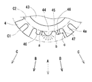
- an arc-shaped first convex portion 44 is provided in a direction rotated by 90 degrees from the position of the pins 41, starting from the center of the deflector 4 (the intersection of the central axis 10 of the nozzle 11 and the straight line L1). .
- arc-shaped first slits 45, 45 are provided on both sides of the first convex portion 44. More specifically, the outer shape of the deflector 4 from one of the first slits 45 through the first convex portion 44 to the other first slit 45 has a wavy shape.
- the first convex portion 44 and the second convex portion 46 adjacent to the first slit 45 are provided inside the outer circumferential circle C1 of the deflector 4.
- the first convex portion 44 and the second convex portion 46 are formed to be shorter than the surrounding convex portions, and have a wavy shape from one first slit 45 to the other first slit 45. .
- the water discharged from the nozzle 11 collides with the button 43 and flows toward the outer periphery of the deflector 4, and a part of the water flowing from the corrugated first convex portion 44 to the second convex portion 46 is After passing through one slit 55, it is evenly spread to a short distance area immediately below and around the sprinkler head S. At this time, a stream of water flows in the direction of the first slits 45, 45 (the direction of arrow B).
- the water flow scattered from the first convex portion 44 is scattered in a radial direction from the edge of the first convex portion 44 as shown by an arrow around the first convex portion 44 in FIG. Therefore, the water flow in the direction of arrow A becomes a mist-like water flow.
- the mist-like water stream scattered in the direction of arrow A is transported to a distance by the airflow generated by the stream of water, and the wall surface extends in the direction of A. Wet.
- the corner between the tip of the second convex portion 46 and the adjacent first slit 45 and second slit 47 has a rounded arc shape, and water scattered from this arc portion is the first convex portion.
- the water is scattered in the radial direction in the same manner as the water scattered from the edge of the portion 44.
- the distance a between the tip of the first convex portion 44 and the arc end of the first slit is preferably set to 1 to 2 mm. If the distance a is too large, the flow of water in the direction of arrow B will increase and the flow of water in the direction of arrow A will tend to decrease.
- the length b of the second convex portion 46 is shorter than the length of the convex portion 4a adjacent thereto.
- the dimension c obtained by subtracting the length of the projection 4a from the length b of the second projection 46 is substantially the same as or slightly longer than the length of the second projection 46.
- the third convex portion 48 is arranged on the straight line L1, and the pin 41 is installed.
- the pin 41 is provided outside the outer circumferential circle C1 of the deflector 4, and the tip of the third convex portion 48 extends outside the outer circumferential circle C1 of the deflector 4.
- a fourth convex portion 49 is provided along a straight line L1, and the tip of the fourth convex portion 49 and the tip of the third convex portion 48 are on a straight line L2 which intersects the straight line L1 perpendicularly. is there.
- the tip of the third projection 48 is bent in a direction away from the nozzle 11 more than the plane of the fourth projection 49, and a step 50 is provided.
- the step 50 is provided with a hole through which the lower end of the pin 41 is inserted. After the pin 41 is inserted through the hole, the pin 41 is fixedly installed on the step 50.
- the third convex portion 48 has a slope 51 near the step 50, and the slope 51 is located outside the outer circumference C ⁇ b> 1 of the deflector 4.
- the third slit 52 between the third convex part 48 and the fourth convex part 49 is installed slightly inclined with respect to the straight line L1. For this reason, the width of the third convex portion 48 becomes narrower toward the distal end.
- the configuration of the sprinkler head S of the present invention described above is not limited to the above, and a glass bulb or a link can be used as the thermal decomposition unit 3, for example.
- the supporting member for connecting the main body and the deflector may be configured as a frame arm extending from the main body in the water discharge direction of the nozzle, and the deflector of the present invention may be installed at the end of the frame arm.
Landscapes
- Health & Medical Sciences (AREA)
- Public Health (AREA)
- Business, Economics & Management (AREA)
- Emergency Management (AREA)
- Fire-Extinguishing By Fire Departments, And Fire-Extinguishing Equipment And Control Thereof (AREA)
- Nozzles (AREA)
Priority Applications (2)
| Application Number | Priority Date | Filing Date | Title |
|---|---|---|---|
| US17/256,747 US11511144B2 (en) | 2018-07-05 | 2019-04-22 | Sprinkler head |
| JP2020528695A JP7284166B2 (ja) | 2018-07-05 | 2019-04-22 | スプリンクラーヘッド |
Applications Claiming Priority (2)
| Application Number | Priority Date | Filing Date | Title |
|---|---|---|---|
| JP2018128127 | 2018-07-05 | ||
| JP2018-128127 | 2018-07-05 |
Publications (1)
| Publication Number | Publication Date |
|---|---|
| WO2020008707A1 true WO2020008707A1 (ja) | 2020-01-09 |
Family
ID=69059446
Family Applications (1)
| Application Number | Title | Priority Date | Filing Date |
|---|---|---|---|
| PCT/JP2019/016949 Ceased WO2020008707A1 (ja) | 2018-07-05 | 2019-04-22 | スプリンクラーヘッド |
Country Status (4)
| Country | Link |
|---|---|
| US (1) | US11511144B2 (enExample) |
| JP (1) | JP7284166B2 (enExample) |
| TW (1) | TWM589058U (enExample) |
| WO (1) | WO2020008707A1 (enExample) |
Cited By (1)
| Publication number | Priority date | Publication date | Assignee | Title |
|---|---|---|---|---|
| JPWO2022220132A1 (enExample) * | 2021-04-15 | 2022-10-20 |
Families Citing this family (2)
| Publication number | Priority date | Publication date | Assignee | Title |
|---|---|---|---|---|
| CN113993597A (zh) * | 2019-05-01 | 2022-01-28 | 维克托里克公司 | 可隐藏的窗户喷洒器 |
| US11439857B2 (en) * | 2019-10-25 | 2022-09-13 | Tyco Fire Products Lp | Systems and methods for fire suppression in a corridor |
Citations (5)
| Publication number | Priority date | Publication date | Assignee | Title |
|---|---|---|---|---|
| US4616710A (en) * | 1984-12-27 | 1986-10-14 | Pilant Frank J | Heat-released plug |
| EP0505672A2 (en) * | 1991-03-25 | 1992-09-30 | Grinnell Corporation | Fire protection sprinkler |
| JPH1024121A (ja) * | 1996-07-10 | 1998-01-27 | Nohmi Bosai Ltd | 泡水溶液噴霧ヘッド |
| JP2012080961A (ja) * | 2010-10-07 | 2012-04-26 | Senju Sprinkler Kk | スプリンクラーヘッド |
| JP2013056084A (ja) * | 2011-09-09 | 2013-03-28 | Senju Sprinkler Kk | スプリンクラーヘッド |
Family Cites Families (9)
| Publication number | Priority date | Publication date | Assignee | Title |
|---|---|---|---|---|
| US3061016A (en) * | 1959-12-14 | 1962-10-30 | Hodgman Mfg Co Inc | Fusible link |
| US3010521A (en) * | 1960-05-03 | 1961-11-28 | Safety First Products Corp | Cantilever sprinkler head for dry powder |
| US6962208B2 (en) * | 2000-05-17 | 2005-11-08 | The Viking Corporation | Compact pendant sprinkler head |
| JP2003325695A (ja) * | 2002-03-06 | 2003-11-18 | Senju Sprinkler Kk | スプリンクラーヘッドカバー |
| US20040134670A1 (en) * | 2002-12-27 | 2004-07-15 | Orr Shawn Gregory | Sprinkler cover |
| US7275603B2 (en) * | 2004-10-26 | 2007-10-02 | The Reliable Automatic Sprinkler Co., Inc. | Concealed pendent fire protection sprinkler with drop-down deflector |
| ATE526061T1 (de) | 2005-06-03 | 2011-10-15 | Tyco Fire Products Lp | Unter einer flachplatte verborgener sprinkler für wohngebäude |
| JP2012040165A (ja) | 2010-08-19 | 2012-03-01 | Senju Sprinkler Kk | スプリンクラーヘッド |
| US9086180B2 (en) * | 2011-07-11 | 2015-07-21 | Frank T. Porta | Quick connect fire and dust suppression system |
-
2019
- 2019-04-22 US US17/256,747 patent/US11511144B2/en active Active
- 2019-04-22 JP JP2020528695A patent/JP7284166B2/ja active Active
- 2019-04-22 WO PCT/JP2019/016949 patent/WO2020008707A1/ja not_active Ceased
- 2019-06-24 TW TW108208040U patent/TWM589058U/zh unknown
Patent Citations (5)
| Publication number | Priority date | Publication date | Assignee | Title |
|---|---|---|---|---|
| US4616710A (en) * | 1984-12-27 | 1986-10-14 | Pilant Frank J | Heat-released plug |
| EP0505672A2 (en) * | 1991-03-25 | 1992-09-30 | Grinnell Corporation | Fire protection sprinkler |
| JPH1024121A (ja) * | 1996-07-10 | 1998-01-27 | Nohmi Bosai Ltd | 泡水溶液噴霧ヘッド |
| JP2012080961A (ja) * | 2010-10-07 | 2012-04-26 | Senju Sprinkler Kk | スプリンクラーヘッド |
| JP2013056084A (ja) * | 2011-09-09 | 2013-03-28 | Senju Sprinkler Kk | スプリンクラーヘッド |
Cited By (2)
| Publication number | Priority date | Publication date | Assignee | Title |
|---|---|---|---|---|
| JPWO2022220132A1 (enExample) * | 2021-04-15 | 2022-10-20 | ||
| JP7780511B2 (ja) | 2021-04-15 | 2025-12-04 | 千住スプリンクラー株式会社 | スプリンクラーヘッド |
Also Published As
| Publication number | Publication date |
|---|---|
| JPWO2020008707A1 (ja) | 2021-08-02 |
| JP7284166B2 (ja) | 2023-05-30 |
| TWM589058U (zh) | 2020-01-11 |
| US20210260423A1 (en) | 2021-08-26 |
| US11511144B2 (en) | 2022-11-29 |
Similar Documents
| Publication | Publication Date | Title |
|---|---|---|
| EP2012881B1 (en) | Extended coverage horizontal sidewall sprinkler | |
| US10238903B2 (en) | Residential concealed sprinkler | |
| US20180369624A1 (en) | Cpvc sprinkler assembly with support member | |
| WO2020008707A1 (ja) | スプリンクラーヘッド | |
| US8783373B2 (en) | Extended coverge horizontal sidewall sprinkler | |
| WO2019123711A1 (ja) | スプリンクラーヘッド | |
| US20240001183A1 (en) | Sprinkler frame support bridge | |
| JP2012080961A (ja) | スプリンクラーヘッド | |
| CN111699025A (zh) | 喷洒头 | |
| US11383114B2 (en) | Sprinkler head | |
| US7699116B2 (en) | Anti-skipping sprinkler | |
| JP2016106656A (ja) | スプリンクラーヘッド | |
| JP2006191961A (ja) | 側壁型スプリンクラーヘッド | |
| JP2019170479A (ja) | スプリンクラーヘッド | |
| JP4768295B2 (ja) | 消火ヘッド | |
| KR102703885B1 (ko) | 소방수의 미세 흐름을 방지할 수 있는 스프링클러 헤드 | |
| JP3012031U (ja) | スプリンクラーヘッド | |
| JP2000153005A (ja) | スプリンクラヘッド取付具 | |
| US20250090882A1 (en) | Sprinkler frame support bridge | |
| JP2014144153A (ja) | スプリンクラーヘッド | |
| US20230234080A1 (en) | Systems and methods of fire suppression in a corridor | |
| KR101804301B1 (ko) | 스프링클러 헤드의 감열장치 | |
| JP6425966B2 (ja) | 消火用ヘッド | |
| JP2020130749A (ja) | スプリンクラヘッド | |
| HK1128437B (en) | Extended coverage horizontal sidewall sprinkler |
Legal Events
| Date | Code | Title | Description |
|---|---|---|---|
| 121 | Ep: the epo has been informed by wipo that ep was designated in this application |
Ref document number: 19830983 Country of ref document: EP Kind code of ref document: A1 |
|
| ENP | Entry into the national phase |
Ref document number: 2020528695 Country of ref document: JP Kind code of ref document: A |
|
| NENP | Non-entry into the national phase |
Ref country code: DE |
|
| 122 | Ep: pct application non-entry in european phase |
Ref document number: 19830983 Country of ref document: EP Kind code of ref document: A1 |