WO2020008634A1 - 機械学習装置、数値制御装置、工作機械および機械学習方法 - Google Patents
機械学習装置、数値制御装置、工作機械および機械学習方法 Download PDFInfo
- Publication number
- WO2020008634A1 WO2020008634A1 PCT/JP2018/025747 JP2018025747W WO2020008634A1 WO 2020008634 A1 WO2020008634 A1 WO 2020008634A1 JP 2018025747 W JP2018025747 W JP 2018025747W WO 2020008634 A1 WO2020008634 A1 WO 2020008634A1
- Authority
- WO
- WIPO (PCT)
- Prior art keywords
- chuck
- standby time
- unit
- work
- workpiece
- Prior art date
- Legal status (The legal status is an assumption and is not a legal conclusion. Google has not performed a legal analysis and makes no representation as to the accuracy of the status listed.)
- Ceased
Links
Images



Classifications
-
- B—PERFORMING OPERATIONS; TRANSPORTING
- B25—HAND TOOLS; PORTABLE POWER-DRIVEN TOOLS; MANIPULATORS
- B25J—MANIPULATORS; CHAMBERS PROVIDED WITH MANIPULATION DEVICES
- B25J9/00—Program-controlled manipulators
- B25J9/16—Program controls
- B25J9/1628—Program controls characterised by the control loop
- B25J9/163—Program controls characterised by the control loop learning, adaptive, model based, rule based expert control
-
- B—PERFORMING OPERATIONS; TRANSPORTING
- B25—HAND TOOLS; PORTABLE POWER-DRIVEN TOOLS; MANIPULATORS
- B25J—MANIPULATORS; CHAMBERS PROVIDED WITH MANIPULATION DEVICES
- B25J9/00—Program-controlled manipulators
- B25J9/16—Program controls
- B25J9/1656—Program controls characterised by programming, planning systems for manipulators
- B25J9/1669—Program controls characterised by programming, planning systems for manipulators characterised by special application, e.g. multi-arm co-operation, assembly, grasping
-
- B—PERFORMING OPERATIONS; TRANSPORTING
- B25—HAND TOOLS; PORTABLE POWER-DRIVEN TOOLS; MANIPULATORS
- B25J—MANIPULATORS; CHAMBERS PROVIDED WITH MANIPULATION DEVICES
- B25J9/00—Program-controlled manipulators
- B25J9/16—Program controls
- B25J9/1612—Program controls characterised by the hand, wrist, grip control
-
- B—PERFORMING OPERATIONS; TRANSPORTING
- B25—HAND TOOLS; PORTABLE POWER-DRIVEN TOOLS; MANIPULATORS
- B25J—MANIPULATORS; CHAMBERS PROVIDED WITH MANIPULATION DEVICES
- B25J9/00—Program-controlled manipulators
- B25J9/16—Program controls
- B25J9/1679—Program controls characterised by the tasks executed
- B25J9/1682—Dual arm manipulator; Coordination of several manipulators
-
- G—PHYSICS
- G05—CONTROLLING; REGULATING
- G05B—CONTROL OR REGULATING SYSTEMS IN GENERAL; FUNCTIONAL ELEMENTS OF SUCH SYSTEMS; MONITORING OR TESTING ARRANGEMENTS FOR SUCH SYSTEMS OR ELEMENTS
- G05B19/00—Program-control systems
- G05B19/02—Program-control systems electric
- G05B19/18—Numerical control [NC], i.e. automatically operating machines, in particular machine tools, e.g. in a manufacturing environment, so as to execute positioning, movement or co-ordinated operations by means of program data in numerical form
-
- G—PHYSICS
- G05—CONTROLLING; REGULATING
- G05B—CONTROL OR REGULATING SYSTEMS IN GENERAL; FUNCTIONAL ELEMENTS OF SUCH SYSTEMS; MONITORING OR TESTING ARRANGEMENTS FOR SUCH SYSTEMS OR ELEMENTS
- G05B19/00—Program-control systems
- G05B19/02—Program-control systems electric
- G05B19/18—Numerical control [NC], i.e. automatically operating machines, in particular machine tools, e.g. in a manufacturing environment, so as to execute positioning, movement or co-ordinated operations by means of program data in numerical form
- G05B19/406—Numerical control [NC], i.e. automatically operating machines, in particular machine tools, e.g. in a manufacturing environment, so as to execute positioning, movement or co-ordinated operations by means of program data in numerical form characterised by monitoring or safety
- G05B19/4065—Monitoring tool breakage, life or condition
-
- G—PHYSICS
- G05—CONTROLLING; REGULATING
- G05B—CONTROL OR REGULATING SYSTEMS IN GENERAL; FUNCTIONAL ELEMENTS OF SUCH SYSTEMS; MONITORING OR TESTING ARRANGEMENTS FOR SUCH SYSTEMS OR ELEMENTS
- G05B19/00—Program-control systems
- G05B19/02—Program-control systems electric
- G05B19/18—Numerical control [NC], i.e. automatically operating machines, in particular machine tools, e.g. in a manufacturing environment, so as to execute positioning, movement or co-ordinated operations by means of program data in numerical form
- G05B19/4155—Numerical control [NC], i.e. automatically operating machines, in particular machine tools, e.g. in a manufacturing environment, so as to execute positioning, movement or co-ordinated operations by means of program data in numerical form characterised by program execution, i.e. part program or machine function execution, e.g. selection of a program
-
- G—PHYSICS
- G06—COMPUTING OR CALCULATING; COUNTING
- G06N—COMPUTING ARRANGEMENTS BASED ON SPECIFIC COMPUTATIONAL MODELS
- G06N20/00—Machine learning
-
- G—PHYSICS
- G06—COMPUTING OR CALCULATING; COUNTING
- G06N—COMPUTING ARRANGEMENTS BASED ON SPECIFIC COMPUTATIONAL MODELS
- G06N20/00—Machine learning
- G06N20/10—Machine learning using kernel methods, e.g. support vector machines [SVM]
-
- G—PHYSICS
- G06—COMPUTING OR CALCULATING; COUNTING
- G06N—COMPUTING ARRANGEMENTS BASED ON SPECIFIC COMPUTATIONAL MODELS
- G06N3/00—Computing arrangements based on biological models
- G06N3/004—Artificial life, i.e. computing arrangements simulating life
- G06N3/006—Artificial life, i.e. computing arrangements simulating life based on simulated virtual individual or collective life forms, e.g. social simulations or particle swarm optimisation [PSO]
-
- G—PHYSICS
- G06—COMPUTING OR CALCULATING; COUNTING
- G06N—COMPUTING ARRANGEMENTS BASED ON SPECIFIC COMPUTATIONAL MODELS
- G06N3/00—Computing arrangements based on biological models
- G06N3/02—Neural networks
- G06N3/08—Learning methods
- G06N3/092—Reinforcement learning
-
- G—PHYSICS
- G05—CONTROLLING; REGULATING
- G05B—CONTROL OR REGULATING SYSTEMS IN GENERAL; FUNCTIONAL ELEMENTS OF SUCH SYSTEMS; MONITORING OR TESTING ARRANGEMENTS FOR SUCH SYSTEMS OR ELEMENTS
- G05B2219/00—Program-control systems
- G05B2219/30—Nc systems
- G05B2219/39—Robotics, robotics to robotics hand
- G05B2219/39505—Control of gripping, grasping, contacting force, force distribution
-
- G—PHYSICS
- G06—COMPUTING OR CALCULATING; COUNTING
- G06N—COMPUTING ARRANGEMENTS BASED ON SPECIFIC COMPUTATIONAL MODELS
- G06N3/00—Computing arrangements based on biological models
- G06N3/02—Neural networks
- G06N3/08—Learning methods
-
- G—PHYSICS
- G06—COMPUTING OR CALCULATING; COUNTING
- G06N—COMPUTING ARRANGEMENTS BASED ON SPECIFIC COMPUTATIONAL MODELS
- G06N3/00—Computing arrangements based on biological models
- G06N3/12—Computing arrangements based on biological models using genetic models
- G06N3/126—Evolutionary algorithms, e.g. genetic algorithms or genetic programming
-
- G—PHYSICS
- G06—COMPUTING OR CALCULATING; COUNTING
- G06N—COMPUTING ARRANGEMENTS BASED ON SPECIFIC COMPUTATIONAL MODELS
- G06N5/00—Computing arrangements using knowledge-based models
- G06N5/04—Inference or reasoning models
Definitions
- the present invention relates to a machine learning device, a numerical control device, a machine tool, and a machine learning method for learning a work transfer operation.
- a machine tool such as a lathe
- the workpiece is fed after the chuck on the receiving side securely grips the workpiece.
- the side chuck needs to release the work.
- the waiting time between the start of the closing chuck of the receiving chuck and the opening of the chuck of the sending side starts opening the work, the longer the work is required to transfer the work. It costs. For this reason, it is desired that the delivery of the work is completed in a short time.
- the chuck on the side receiving the work performs the closing operation while rotating and swinging about the axis of the work, and the chuck on the side receiving the work performs the closing operation.
- the swing of the chuck is stopped by grasping the workpiece, it is determined that the gripping of the work has been completed, and the chuck on the sending side has released the work.
- Patent Literature 1 since the closing operation needs to be performed at a low speed so that the work is not damaged even if the workpiece is gripped while rotating and swinging, it takes time to close the chuck. Therefore, there is a problem that the delivery of the work cannot be completed in a short time.
- the present invention has been made in view of the above, and an object of the present invention is to provide a machine learning device capable of completing a work transfer in a short time.
- the present invention provides a second chuck for transferring a workpiece between a first chuck for gripping and feeding a workpiece and a second chuck for gripping and receiving the workpiece.
- a machine learning device for learning a standby time for at least one of gripping of a workpiece by a chuck and opening of a workpiece by a first chuck comprising: a standby time and a feedback current from a driving mechanism for moving the first chuck. It is characterized by comprising a state observing unit for observing as a state variable, and a learning unit for learning a standby time for shortening a work transfer time according to a data set created based on the state variable.
- the machine learning device has an effect that the delivery of a work can be completed in a short time.
- FIG. 1 is a diagram illustrating a configuration of a control system including a numerical control device according to an embodiment.
- 4 is a flowchart illustrating an operation procedure of the machining system according to the embodiment.
- FIG. 2 is a diagram illustrating an example of a hardware configuration of a numerical control device according to an embodiment.
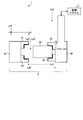
- FIG. 1 is a diagram illustrating a configuration of a machining system according to an embodiment.
- FIG. 1 shows a case where the machining system 1 is viewed from a vertical direction.
- the vertical direction is the Y-axis direction
- the horizontal direction which is the moving direction of the work 40, is the X-axis direction and the Z-axis direction.
- the machine system 1 includes a machine tool 2 for machining a workpiece 40 and a control system 3 for controlling the operation of the machine tool 2.
- Examples of the machine tool 2 are a lathe and a machining center.
- a case where the machine tool 2 is a lathe will be described.
- the machine tool 2 includes a rotating unit 35, a loader chuck 32 serving as a first chuck, a spindle chuck 31 serving as a second chuck, and a loader 36 serving as a transfer mechanism for a workpiece 40.
- the operation of the loader 36 is controlled by the control system 3.
- the loader chuck 32 is connected to the loader 36 and moves together with the loader 36.
- the loader chuck 32 can grip a workpiece 40 which is a workpiece. Examples of the loader chuck 32 are a three-jaw chuck and a collet chuck.
- the loader chuck 32 transfers the work 40 to the spindle chuck 31 when starting the processing of the work 40, and receives the work 40 from the spindle chuck 31 after the processing of the work 40 is completed.
- the rotation unit 35 rotates around the Z axis, which is the main axis, as a rotation axis.
- the spindle chuck 31 is connected to the rotating unit 35 and rotates together with the rotating unit 35.
- the spindle chuck 31 can hold the work 40.
- Examples of the spindle chuck 31 are a three-jaw chuck and a collet chuck.
- the rotating unit 35 rotates while the spindle chuck 31 holds the work 40, thereby rotating the work 40.
- An example of the rotating unit 35 is a spindle mechanism.
- the machine tool 2 grips one end of the work 40 with the loader chuck 32 when loading the work 40 on the rotating unit 35.
- the loader 36 moves to the minus side in the X-axis direction and stops at the position facing the spindle chuck 31 (s0). Then, the loader 36 moves to the minus side in the Z-axis direction.
- the loader 36 moves the work 40 to a position where the spindle chuck 31 can grip the work 40 (s1).
- the position of the loader 36 where the spindle chuck 31 can grip the work 40 is a desired delivery position.
- the machine tool 2 gives a closing operation command to the spindle chuck 31 using an auxiliary function such as an M code to start the closing operation (s2).
- the spindle chuck 31 grips the workpiece 40. (S3).
- the time when the spindle chuck 31 is considered to complete the gripping of the work 40 is a gripping standby time 61 described later.
- the holding standby time 61 elapses, the other holding of the workpiece 40 by the spindle chuck 31 is completed.
- the machine tool 2 After the elapse of the gripping standby time 61, which is the first standby time, and further confirming that the spindle chuck 31 has gripped the workpiece 40, the machine tool 2 gives the loader chuck 32 an opening operation command to perform the opening operation. Is started (s4), and after giving the command of the opening operation, the loader chuck 32 waits for a time considered to complete the opening of the work 40 (s5). The time when the loader chuck 32 is considered to complete the opening of the work 40 is an opening standby time 62 described later. When the release standby time 62 that is the second standby time has elapsed, the release of the work 40 by the loader chuck 32 is completed.
- the loader 36 moves to the plus side in the Z-axis direction. As a result, the loader 36 retreats in the direction away from the work 40 (s6), and further moves to the plus side in the X-axis direction.
- each process from s0 to s6 is a process in the reverse direction. That is, in the processing of s0 and s6, the moving direction of the loader 36 is reversed between the time of loading and the time of unloading. At the time of unloading, the closing operation of the loader chuck 32 and the opening operation of the spindle chuck 31 are performed.
- the loader 36 moves to the minus side in the X-axis direction, and further moves in a direction approaching the work 40. Then, the loader chuck 32 starts the closing operation and waits for the holding standby time 61. After the elapse of the holding standby time 61 and the confirmation that the loader chuck 32 has gripped the work 40, the spindle chuck 31 starts the opening operation and waits for the opening standby time 62. After the release standby time 62 has elapsed and it is confirmed that the spindle chuck 31 has released the work 40, the loader 36 retreats in a direction away from the work 40, and further moves to the plus side in the X-axis direction.
- the holding waiting time 61 when the work 40 is loaded on the rotating unit 35 and the holding waiting time 61 when the work 40 is unloaded from the rotating unit 35 may be different from each other. Further, the opening standby time 62 for loading the work 40 on the rotating unit 35 and the opening standby time 62 for unloading the work 40 from the rotating unit 35 may be different times. Since the process of loading the work 40 into the rotating unit 35 and the process of unloading the work 40 from the rotating unit 35 are the same, the process of loading the work 40 into the rotating unit 35 will be described below.
- the machine tool 2 has a peculiar habit in a process of gripping the work 40, a transfer process, and the like. Therefore, the time from when the command for the closing operation is given to the spindle chuck 31 to when the closing operation is completed, and the time from when the command for the opening operation is given to the loader chuck 32 to when the opening operation is completed are determined by the machine tool 2. Different for each.
- a numerical control (NC: Numerical Control) device 10 described later provided in the control system 3 performs a proper holding standby time 61 used when the loader chuck 32 attempts to transfer the work 40 to the spindle chuck 31. And the opening standby time 62 is learned. That is, the numerical controller 10 learns the holding standby time 61 and the release standby time 62, thereby reducing unnecessary standby time, and thereby shortening the delivery time of the work 40.
- the control system 3 may learn one of the holding waiting time 61 and the opening waiting time 62. That is, the control system 3 learns at least one of the holding standby time 61 and the release standby time 62.
- FIG. 2 is a diagram illustrating a configuration of a control system including the numerical control device according to the embodiment.
- the control system 3 includes a numerical control device 10, a drive unit 37, and a servomotor 38.
- the numerical controller 10 is a computer that controls the position of the loader 36 by sending a position command 53 to the drive unit 37.
- the position command 53 sent by the numerical controller 10 to the drive unit 37 is a command specifying the position of the loader 36, and includes a position command in the X-axis direction and a position command in the Z-axis direction.
- the numerical controller 10 controls the transfer of the work 40 from the loader chuck 32 to the spindle chuck 31 and, if the transfer fails, changes the holding standby time 61 and the release standby time 62 to control the transfer again. I do.
- the numerical controller 10 pulls back the loader chuck 32 to the positive side in the Z-axis direction after the holding standby time 61, and learns an appropriate holding standby time 61 based on the current value of the current sent to the servomotor 38 at the time of pulling back. . Further, the numerical controller 10 pulls back the loader chuck 32 to the positive side in the Z-axis direction after the opening standby time 62, and sets an appropriate opening standby time 62 based on the current value of the current sent to the servomotor 38 at the time of pulling back. learn.
- the drive unit 37 is a drive mechanism that moves the loader 36 by driving a servo motor 38.
- the drive unit 37 calculates a current value to be sent to the servomotor 38 based on the position command 53 from the numerical controller 10.
- the drive unit 37 drives the servo motor 38 by sending a current corresponding to the position command 53 to the servo motor 38.
- the drive unit 37 sends a feedback (FB: Feed-Back) current 55, which is data indicating a current to be sent to the servomotor 38, to the numerical controller 10.
- FB Feed-Back
- the servomotor 38 is connected to the loader 36 and moves the loader 36 according to the current from the drive unit 37.
- the servomotors 38 include a servomotor that moves the loader 36 in the X-axis direction and a servomotor that moves the loader 36 in the Z-axis direction.
- the numerical control device 10 includes a control processing program storage unit 11, an analysis unit 12, a control unit 13, a storage unit 14, a sequence control unit 15, and a machine learning device 20.
- the control processing program storage unit 11 stores a control processing program used when processing the work 40.
- the control machining program includes a loading command 60 for loading the work 40 on the rotating unit 35, a machining command for machining the work 40, and an unloading command for unloading the work 40 from the rotating unit 35. include.
- FIG. 2 illustrates the loading command 60. Among these commands, the loading command 60 and the unloading command are dedicated commands for transferring the work 40.
- the loading command 60 is sent to the analysis unit 12 as a G code 51 for positioning the loader 36.
- the analysis unit 12 analyzes the control machining program.
- the analysis unit 12 determines whether or not the analyzed command is a dedicated command. If the analyzed command is a dedicated command such as the loading command 60, transfer position information indicating a position at which the workpiece 40 is transferred based on the G code 51. 52, a holding waiting time 61, and an opening waiting time 62 are generated.
- the transfer position information 52 is information of a position at which the work 40 is transferred between chucks between the loader chuck 32 and the spindle chuck 31. Specifically, the delivery position information 52 is an end point of the loader 36. At the time of the first delivery execution of the work 40, information used for the delivery operation is set by the argument of the dedicated command.
- the dedicated command includes the following command arguments (A1) to (A9).
- Reference current value C1 as a criterion for determining whether or not gripping is completed (A4) Movement amount L1 of loader chuck 32 used for gripping confirmation operation (A5)
- a reference current value C2 which is a criterion for determining whether or not the opening is completed.
- the grip standby time 61 described in (A1) is a wait time from when a command for a closing operation is given to the spindle chuck 31 to when a command for confirming that gripping by the spindle chuck 31 is completed is given. .
- the opening standby time 62 of (A2) is a waiting time from when an opening operation command is given to the loader chuck 32 to when a command for confirming that the spindle chuck 31 has completed opening is given.
- the reference current value C1 of (A3) is a value for determining whether or not the gripping by the spindle chuck 31 is completed, and is compared with the FB current 55 of the current sent to the servomotor 38.
- the FB current 55 of the present embodiment indicates a current sent to the servo motor of the servo motor 38 that moves the loader 36 in the Z-axis direction.
- the movement amount L1 of (A4) is a distance to pull back the loader chuck 32 holding the workpiece 40 to the positive side in the Z-axis direction in order to confirm that the gripping by the spindle chuck 31 is completed.
- the reference current value C2 of (A5) is a value for determining whether the loader chuck 32 has completed opening and is compared with the FB current 55 of the current sent to the servomotor 38.
- the loader chuck 32 does not open the work 40, and the loader chuck 32 attempts to pull the work 40 back.
- the movement amount L2 of (A6) is a distance to return the loader chuck 32 to the positive side in the Z-axis direction in order to confirm that the opening by the loader chuck 32 is completed.
- the function number X1 in (A7) is a number indicating a spindle opening command 63 that is an opening command to the spindle chuck 31, and the function number X2 is a number indicating a spindle closing command 64 that is a closing command to the spindle chuck 31. is there.
- the function number Y1 in (A8) is a number indicating a loader open command 65 that is an open command to the loader chuck 32, and the function number Y2 is a loader close command 66 that is a close command to the loader chuck 32. Number.
- the transfer position information 52 in (A9) includes the X coordinate and the Z coordinate.
- the analysis unit 12 calculates (A1) the holding standby time 61, (A2) the opening standby time 62, (A4) the moving amount L1, (A6) the moving amount L2, and (A7) the function number X1 and (A7).
- X2, the function numbers Y1 and Y2 of (A8), and the transfer position information 52 of (A9) are sent to the control unit 13. Further, the analysis unit 12 sends the reference current value C1 of (A3) and the reference current value C2 of (A5) to the machine learning device 20.
- the analysis unit 12 is not limited to acquiring the value of the command argument from the dedicated command, but may acquire the value corresponding to the command argument from the parameter. In this case, information corresponding to the command argument is stored in the storage unit 14 as a parameter.
- the control unit 13 generates a position command 53 according to the transfer position information 52 sent from the analysis unit 12.
- the control unit 13 sends the position command 53 to the drive unit 37.
- the control unit 13 controls the spindle open command 63, the spindle close command 64, the loader open command 65, and the main shaft open command 63 in accordance with the grip standby time 61 and the open standby time 62 sent from the analysis unit 12.
- a loader closing command 66 is generated and sent to the sequence control unit 15.
- the control unit 13 measures the time designated by the holding waiting time 61 and the opening waiting time 62 by the software timer.
- the spindle open command 63, the spindle close command 64, the loader open command 65, or the loader close command 66 may be referred to as an open / close command.
- the control unit 13 generates an opening / closing command according to the actions 58A and 58B given from the machine learning device 20 at the time of the second and subsequent delivery of the work 40.
- the action 58A is the next holding waiting time 61
- the action 58B is the next opening waiting time 62.
- the control unit 13 sends the actually used grip standby time 61 and the release standby time 62 to the machine learning device 20.
- control unit 13 When the control unit 13 receives an instruction specifying the function number X1 from the analysis unit 12, the control unit 13 generates a spindle opening command 63 corresponding to the function number X1 and sends it to the sequence control unit 15.
- the control unit 13 When receiving an instruction specifying the function number X2 from the analysis unit 12, the control unit 13 generates a spindle closing command 64 corresponding to the function number X2, and sends the command to the sequence control unit 15.
- the control unit 13 when receiving an instruction specifying the function number Y1 from the analysis unit 12, the control unit 13 generates a loader opening instruction 65 corresponding to the function number Y1 and sends it to the sequence control unit 15.
- the control unit 13 when receiving an instruction specifying the function number Y2 from the analysis unit 12, the control unit 13 generates a loader closing command 66 corresponding to the function number Y2 and sends it to the sequence control unit 15.
- control unit 13 When the control unit 13 receives a notification from the machine learning device 20 indicating that the FB current 55 is equal to or more than the reference current value C1 after the closing operation of the spindle chuck 31, the control unit 13 starts the opening operation of the loader chuck 32.
- control unit 13 When the control unit 13 receives a notification indicating that the FB current 55 is smaller than the reference current value C1 from the machine learning device 20 after closing the spindle chuck 31, the control unit 13 opens the spindle chuck 31, and then performs the spindle operation. The closing operation of the chuck 31 is performed again.
- control unit 13 When the control unit 13 receives a notification from the machine learning device 20 indicating that the FB current 55 is equal to or less than the reference current value C2 after opening the loader chuck 32, the control unit 13 starts the retreat operation of the loader 36.
- the sequence control unit 15 When the control unit 13 receives a notification from the machine learning device 20 indicating that the FB current 55 is larger than the reference current value C2 after opening the loader chuck 32, the sequence control unit 15 closes the loader chuck 32. After that, the sequence controller 15 causes the loader chuck 32 to open again.
- the machine learning device 20 includes a state observation unit 25 and a learning unit 21.
- the state observation unit 25 acquires the reference current value C1 of (A3) and the reference current value C2 of (A5) among the command arguments from the analysis unit 12.
- the state observation unit 25 acquires the holding standby time 61 and the release standby time 62 from the control unit 13 and acquires the FB current 55 from the drive unit 37.
- the state observation unit 25 uses the FB current 55 and the reference current value C1 when determining whether or not the gripping of the work 40 by the spindle chuck 31 has been completed.
- the state observation unit 25 uses the FB current 55 and the reference current value C2 when determining whether the opening of the work 40 by the loader chuck 32 has been completed.
- the state observation unit 25 observes the holding standby time 61 and the FB current 55 during the holding operation as the state variable 56A
- the open standby time 62 and the FB current 55 during the open operation are observed as state variables 56B
- the state variables 56A and 56B as observation results are sent to the learning unit 21. That is, the state variable 56A that the state observation unit 25 sends to the learning unit 21 includes the holding standby time 61 and the FB current 55 during the holding operation, and the state variable 56B includes the opening standby time 62 and the FB during the opening operation.
- a current 55 is included.
- the holding waiting time 61 is too short, the FB current 55 is smaller than the reference current value C1 because the loader chuck 32 pulls the work 40 back to the plus side in the Z-axis direction before the spindle chuck 31 holds the work 40. Become.
- the holding standby time 61 is long enough, after the spindle chuck 31 holds the work 40, the loader chuck 32 attempts to pull the work 40 back to the plus side in the Z-axis direction, so that the FB current 55 It becomes equal to or more than the reference current value C1.
- the release waiting time 62 is too short, the loader chuck 32 attempts to pull the work 40 back to the plus side in the Z-axis direction before the loader chuck 32 releases the work 40. It becomes larger than C1.
- the opening standby time 62 is long enough, after the loader chuck 32 releases the work 40, the loader chuck 32 pulls the work 40 back to the plus side in the Z-axis direction. It is equal to or less than the value C1.
- the state observation unit 25 determines that the spindle chuck 31 has not completed the gripping of the work 40, that is, the gripping has failed. Is determined.
- the state observation unit 25 determines that the loader chuck 32 has not completed opening the work 40, that is, failed to open the work 40. Is determined.
- the state observation unit 25 sends the gripping determination result and the release determination result to the control unit 13.
- the learning unit 21 learns the action 58A that is the next holding waiting time 61 according to the state variable 56A, and learns the action 58B that is the next opening waiting time 62 according to the state variable 56B. That is, the learning unit 21 can hold the workpiece 40 by the spindle chuck 31 and shorten the holding standby time 61, and hold the loader chuck 32 to release the work 40, Further, the opening standby time 62 that can shorten the opening standby time 62 is learned.
- the learning unit 21 learns the action 58A according to a data set created based on the state variable 56A including the holding standby time 61 and the FB current 55 during the holding operation. Further, the learning unit 21 learns the behavior 58B according to a data set created based on the state variable 56B including the opening standby time 62 and the FB current 55 during the opening operation.
- the learning unit 21 includes a function updating unit 22 and a reward calculating unit 23.
- the reward calculator 23 calculates the reward 57A based on the state variable 56A, and calculates the reward 57B based on the state variable 56B. That is, the reward calculation unit 23 calculates the reward 57A of the gripping operation based on the holding standby time 61 and the FB current 55 during the gripping operation, and releases the reward 57A based on the opening standby time 62 and the FB current 55 during the opening operation. The motion reward 57B is calculated.
- the reward calculator 23 increases the reward 57A of the gripping operation as the grip standby time 61 is shorter. In addition, the reward calculation unit 23 increases the reward 57B of the opening operation as the opening standby time 62 is shorter.
- the function update unit 22 stores a function for determining the actions 58A and 58B, updates a function for determining the action 58A based on the reward 57A, and determines the action 58B based on the reward 57B. Update the function of.
- An example of a function for determining the actions 58A and 58B is an action value function Q (s t , a t ) described later.
- the function updating unit 22 of the present embodiment updates the action value function Q (s, a) such that the holding standby time 61 and the release standby time 62 become shorter each time the transfer operation of the work 40 is repeated in the machine tool 2. Update.
- the function updating unit 22 calculates the actions 58A and 58B using the updated action value function Q (s, a).
- the function update unit 22 sends the calculated behaviors 58A and 58B to the control unit 13 and sends the storage unit 14 the previous learning data, the data used for learning, and the data necessary for controlling the loader 36.
- An example of the learning data is the next-time holding standby time 61 and the release standby time 62 calculated when the delivery is successful.
- An example of the data used for learning is the action value function used by the learning unit 21 at the time of learning. Q (s, a).
- Examples of data used for controlling the loader 36 are the above-described dedicated commands (A1) to (A6).
- the storage unit 14 stores learning data up to the previous time, data used for learning, and data necessary for controlling the loader 36 by the control unit 13.
- action value function Q which is used to determine the action 58A (s t, a t) and, action value function Q which is used to determine the action 58B (s t, a t) and may be a different function .
- FIG. 3 is a flowchart illustrating an operation procedure of the machining system according to the embodiment.
- the numerical controller 10 moves the loader 36 to the delivery position instructed by the position command 53 of (A9) when the delivery of the workpiece 40 is the first time, that is, when the learning is not yet performed. Is started (step ST10).
- the control unit 13 sends a position command 53 to the drive unit 37. Accordingly, the loader 36 moves in the X-axis direction with the loader chuck 32 gripping the work 40, and then moves in the Z-axis direction.
- the drive unit 37 acquires the FB current 55 for each specific cycle and sends it to the state observation unit 25. Thereby, the state observation unit 25 monitors the FB current 55.
- the control unit 13 sends a spindle closing command 64 to the sequence control unit 15, and the sequence control unit 15 causes the spindle chuck 31 to start a closing operation (step ST11). Then, the control unit 13 waits for the holding standby time 61 (step ST12). At this time, the control unit 13 sends the holding standby time 61 to the state observation unit 25. Note that, when the delivery of the work 40 is the first time, that is, when the work 40 has not been learned, the control unit 13 waits for the above-described holding standby time 61 of (A1). At the time of the second and subsequent delivery of the work 40, the control unit 13 waits for an action 58 ⁇ / b> A which is the next holding standby time 61 given from the machine learning device 20.
- the control unit 13 executes a holding confirmation operation (step ST13). Specifically, the control unit 13 sends a position command to the drive unit 37 for pulling back the loader chuck 32 to the plus side in the Z-axis direction by the movement amount L1.
- the state observation unit 25 sends a state variable 56A including the FB current 55 at this time and the reference current value C1 to the learning unit 21. Thereby, the learning unit 21 learns an appropriate holding standby time 61 according to the state variable 56A (step ST14).
- the learning unit 21 sets a small reward 57A with respect to the gripping standby time 61 used for delivery, and when the gripping of the work 40 is successful, the learning unit 21 A reward 57A having a large value is set for the holding standby time 61 used for delivery. Then, the learning unit 21 determines the action 58A that is the next holding standby time 61 so that the reward 57A of the holding operation is maximized.
- the numerical controller 10 executes the transfer of the work 40 at a certain holding standby time 61, and if the grip operation is successful and the grip is successful, sets a shorter holding standby time 61 and sets If the gripping fails in the operation check, a longer gripping standby time 61 is set.
- the numerical control device 10 learns by repeating these setting processes, and uses the learned result to perform the delivery with the optimal holding standby time 61 when delivering the actual product processing. As described above, the numerical controller 10 learns the holding standby time 61 so that the holding standby time 61 decreases.
- the numerical controller 10 may learn the holding standby time 61 before executing the actual product processing, or may learn the holding standby time 61 when executing the actual product processing. Further, the numerical control device 10 may learn the holding standby time 61 both before and after executing the actual product processing.
- the state observation unit 25 determines whether or not the FB current 55 at the time of performing the gripping confirmation operation is equal to or more than the reference current value C1 (step ST15). When the FB current 55 is smaller than the reference current value C1 (Step ST15, No), the control unit 13 sends the spindle opening command 63 to the spindle chuck 31 to open the spindle chuck 31 (Step ST16).
- the machining system 1 repeats the processing of steps ST11 to ST15.
- the control unit 13 sends a loader opening command 65 to the sequence control unit 15, and the sequence control unit 15 starts the opening operation on the loader chuck 32. (Step ST21).
- the control unit 13 waits for the opening standby time 62 (step ST22).
- the control unit 13 sends the opening standby time 62 to the state observation unit 25.
- the delivery of the work 40 is the first time, that is, when the learning is not performed
- the control unit 13 waits for the opening standby time 62 of (A2) described above.
- the control unit 13 waits for an action 58 ⁇ / b> B that is the next opening standby time 62 given from the machine learning device 20.
- the control unit 13 After the opening standby time 62 has elapsed, the control unit 13 performs an opening confirmation operation (step ST23). Specifically, the control unit 13 sends to the drive unit 37 a position command for pulling back the loader chuck 32 to the plus side in the Z-axis direction by the movement amount L2.
- the state observation unit 25 sends a state variable 56B including the FB current 55 at this time and the reference current value C2 to the learning unit 21. Thereby, the learning unit 21 learns an appropriate opening standby time 62 according to the state variable 56B (step ST24).
- the learning unit 21 sets a reward 57B of a small value with respect to the opening standby time 62 used for delivery, and when the opening of the work 40 is successful, the learning unit 21 A reward 57B having a large value with respect to the open standby time 62 used for delivery is set. Then, the learning unit 21 determines the action 58B that is the next opening standby time 62 so that the reward 57B of the opening operation is maximized.
- the numerical control device 10 executes the transfer of the work 40 with the opening standby time 62 of a certain setting, and if the opening is successfully confirmed by the opening operation confirmation, sets the shorter opening standby time 62 and sets the opening standby time 62 shorter. If the release fails in the operation check, a longer release wait time 62 is set.
- the numerical control device 10 learns by repeating these setting processes, and uses the learned result to perform the delivery with the optimal opening standby time 62 when delivering the actual product processing. As described above, the numerical controller 10 learns the opening standby time 62 so that the opening standby time 62 decreases.
- the numerical controller 10 may learn the opening standby time 62 before performing the actual product processing, or may learn the opening standby time 62 when performing the actual product processing. Further, the numerical control device 10 may learn the opening standby time 62 both before and after performing the actual product processing.
- the state observation unit 25 determines whether or not the FB current 55 at the time of performing the opening confirmation operation is equal to or less than the reference current value C2 (step ST25). When the FB current 55 is larger than the reference current value C2 (Step ST25, No), the control unit 13 sends the loader closing command 66 to the loader chuck 32 to close the loader chuck 32 (Step ST26).
- Step ST25 the control unit 13 retracts the loader 36 to the plus side in the Z-axis direction (Step ST30).
- Step ST30 the sequence of the dedicated command is completed.
- the machine learning device 20 does not need to perform the learning of the holding standby time 61 and the release standby time 62 at every delivery.
- the machine learning device 20 only has to learn the holding standby time 61 and the release standby time 62 once every specific number of times when the workpiece 40 is delivered.
- the machine learning device 20 may change the learning frequency according to the amount of change of the rewards 57A and 57B, the holding waiting time 61 or the opening waiting time 62.
- the machine learning apparatus 20 When the work 40 is unloaded from the spindle chuck 31 to the loader 36, the machine learning apparatus 20 performs the same processing as the case where the work 40 is loaded from the loader 36 to the spindle chuck 31, and the holding standby time 61 and The opening wait time 62 is learned.
- the learning process of the actions 58A and 58B by the learning unit 21 will be described.
- the learning algorithm used for the learning unit 21 may be any learning algorithm.
- reinforcement learning Reinforcement @ Learning
- an agent acting as an agent in a certain environment observes the current state indicated by state variables 56A and 56B, and determines actions 58A and 58B to be taken based on the observation result.
- the agent obtains rewards 57A and 57B from the environment by selecting the behaviors 58A and 58B, and learns a policy that maximizes the rewards 57A and 57B through a series of behaviors 58A and 58B.
- Q learning Q-Learning
- TD-Learning TD learning
- action value table a general update equation (action value table) of the action value function Q (s, a)
- equation (1) an example of the action value table is the action value function Q (s, a) of Expression (1).
- s t represents the environment at time t
- a t represents the behavior in time t.
- the environment is changed to s t + 1.
- rt + 1 represents rewards 57A and 57B obtained by a change in the environment
- ⁇ represents a discount rate
- ⁇ represents a learning coefficient. If you apply the Q-learning, the next gripping the waiting time 61 and the next open waiting time 62 of the delivery operation is the action a t.
- the update expression represented by the expression (1) increases the action value Q if the action value of the best action a at the time t + 1 is larger than the action value Q of the action a executed at the time t. In this case, the action value Q is reduced. In other words, the action value function Q (s, a) is updated so that the action value Q of the action a at the time t approaches the best action value at the time t + 1. As a result, the best action value in one environment is sequentially propagated to the action value in the previous environment.
- the reward calculation unit 23 calculates a reward 57A for the gripping operation based on the holding standby time 61 and the FB current 55 during the gripping operation, and based on the opening standby time 62 and the FB current 55 during the opening operation, performs the opening operation.
- the reward 57B is calculated.
- the reward calculation unit 23 increases the reward 57A of the gripping operation when the FB current 55 becomes equal to or more than the reference current value C1 in the gripping standby time 61 shorter than the shortest gripping standby time 61 that has been successfully gripped so far. . At this time, the reward calculation unit 23 gives a reward 57A of, for example, “1”. Further, when the FB current 55 becomes equal to or less than the reference current value C2 in the opening standby time 62 that is shorter than the shortest opening standby time 62 that has been successfully opened, the reward calculation unit 23 generates the opening operation reward 57B. Increase. At this time, the reward calculator 23 gives a reward 57B of, for example, “1”.
- the reward calculation unit 23 reduces the reward 57A of the gripping operation. At this time, the reward calculator 23 gives a reward 57A of, for example, “ ⁇ 1”.
- the reward calculator 23 reduces the reward 57B of the opening operation. At this time, the reward calculation unit 23 gives a reward 57B of, for example, “ ⁇ 1”.
- the reward calculation unit 23 sets the reward 57A of the holding operation as the maximum reward.
- the reward calculation unit 23 sets the reward 57B for the opening operation as the maximum reward.
- the reward calculation unit 23 regards the reward 57A of the gripping operation as the minimum reward because it is considered that the gripping has failed.
- the reward calculation unit 23 regards the opening operation reward 57B as the minimum reward because it is regarded as an opening failure.
- the reward calculation unit 23 sends the calculated rewards 57A and 57B to the function update unit 22.
- the function updating unit 22 updates a function for determining the action 58A according to the reward 57A calculated by the reward calculating unit 23, and updates a function for determining the action 58B according to the reward 57B calculated by the reward calculating unit 23.
- an action value function Q (s t , a t ) represented by Expression (1) is a function for calculating the actions 58A and 58B, and is updated by the function update unit 22.
- FIG. 4 is a diagram illustrating a relationship between the loader pullback command amount and the FB current when the spindle chuck has completed gripping in the machining system according to the embodiment.
- the horizontal axis represents the loader pullback command amount
- the vertical axis represents the FB current 55.
- the FB current 55 increases. Specifically, when the retraction of the loader chuck 32 is started from a state where the loader chuck 32 is stopped, the FB current 55 also increases as the loader retraction command amount increases, and thereafter, the FB current 55 is reduced to the reference current value C1. It becomes constant with the above values. Therefore, when the FB current 55 is equal to or greater than the reference current value C1, the state observation unit 25 can determine that the spindle chuck 31 has completed gripping the work 40. In this case, the reward calculation unit 23 increases the reward 57A as the holding standby time 61 is shorter.
- FIG. 5 is a diagram showing the relationship between the loader pullback command amount and the FB current when the spindle chuck has not completed gripping in the machining system according to the embodiment.
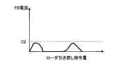
- FIG. 6 is a diagram illustrating a relationship between the loader pullback command amount and the FB current when the loader chuck has completed opening in the machining system according to the embodiment.
- the state observation unit 25 can determine that the loader chuck 32 has completed opening the work 40. In this case, the reward calculation unit 23 increases the reward 57B as the opening standby time 62 is shorter.
- FIG. 7 is a diagram illustrating a relationship between the loader pullback command amount and the FB current when the loader chuck has not completed opening in the machining system according to the embodiment.
- the state observation unit 25 can determine that the loader chuck 32 has not completed opening the work 40. In this case, the reward calculation unit 23 decreases the reward 57B regardless of the length of the opening standby time 62.
- the machine learning device 20 confirms whether or not the workpiece 40 has been gripped by the spindle chuck 31. If the gripping of the workpiece 40 has not been completed, the gripping of the workpiece 40 is performed according to the grip standby time 61. Since the process is executed again, the holding standby time 61 can be corrected. Further, since the machine learning device 20 learns the holding standby time 61, it is possible to prevent a failure in holding. Further, since the machine learning device 20 can re-execute the gripping of the workpiece 40 and prevent failure of the gripping, the productivity of the machine tool 2 is improved.
- the machine learning device 20 checks whether or not the work 40 has been released by the loader chuck 32, and if the work 40 has not been completely opened, the work 40 is released again according to the opening standby time 62. Since it is executed, the opening standby time 62 can be corrected. Further, since the machine learning device 20 learns the opening standby time 62, opening failure can be prevented. In addition, since the machine learning device 20 can re-execute the release of the work 40 and prevent failure of the release, the productivity of the machine tool 2 is improved.
- the machine learning device 20 determines the grip and release of the work 40 based on the FB current 55, it is necessary to provide a special mechanism or device such as a camera for confirming the grip and release of the work 40. Absent. Therefore, it is possible to confirm the grip and release of the work 40 at low cost.
- the machine learning apparatus 20 causes the gripping of the work 40 to be performed again according to the gripping standby time 61. Therefore, even if the gripping standby time 61 is too short, the machine learning device 20 manually recovers. Need not be done.
- the machine learning device 20 causes the opening of the work 40 again according to the opening standby time 62, so that even if the opening standby time 62 is too short, the machine learning device 20 manually recovers. Need not be done. Therefore, the time required for delivery of the work 40 can be shortened, and deterioration in productivity can be suppressed.
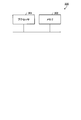
- FIG. 8 is a diagram illustrating an example of a hardware configuration of the numerical control device according to the embodiment.
- the numerical controller 10 can be realized by the control circuit 300 shown in FIG.
- An example of the processor 301 is a CPU (Central Processing Unit), a central processing unit, a processing unit, an arithmetic unit, a microprocessor, a microcomputer, a processor, a DSP (Digital Signal Processor), or a system LSI (Large Scale Integration).
- Examples of the memory 302 are a RAM (Random Access Memory) and a ROM (Read Only Memory).
- the numerical controller 10 is realized by the processor 301 reading and executing a program stored in the memory 302 for executing the operation of the numerical controller 10. It can also be said that this program causes a computer to execute the procedure or method of the numerical control device 10.
- the memory 302 is also used as a temporary memory when the processor 301 executes various processes.
- the numerical control device 10 may be realized by dedicated hardware, and some may be realized by software or firmware. Further, the machine learning device 20 may be realized by the control circuit 300 shown in FIG.
- the machine learning device 20 may learn the holding standby time 61 and the opening standby time 62 based on the FB current detected on the spindle chuck 31 side.
- the machine learning device 20 may perform other known methods such as a neural network, a genetic programming, and a functional logic programming.
- Machine learning may be performed according to a support vector machine or the like.
- the holding standby time 61 and the opening standby time 62 for shortening the delivery time of the work 40 between the chucks are learned according to the data set created based on the state variables 56A and 56B. Delivery of the work 40 can be completed in a short time.
Landscapes
- Engineering & Computer Science (AREA)
- Physics & Mathematics (AREA)
- Theoretical Computer Science (AREA)
- General Physics & Mathematics (AREA)
- Software Systems (AREA)
- Mechanical Engineering (AREA)
- Robotics (AREA)
- Data Mining & Analysis (AREA)
- Evolutionary Computation (AREA)
- Computing Systems (AREA)
- General Engineering & Computer Science (AREA)
- Artificial Intelligence (AREA)
- Mathematical Physics (AREA)
- Human Computer Interaction (AREA)
- Manufacturing & Machinery (AREA)
- Automation & Control Theory (AREA)
- General Health & Medical Sciences (AREA)
- Health & Medical Sciences (AREA)
- Computer Vision & Pattern Recognition (AREA)
- Medical Informatics (AREA)
- Molecular Biology (AREA)
- Computational Linguistics (AREA)
- Biophysics (AREA)
- Biomedical Technology (AREA)
- Life Sciences & Earth Sciences (AREA)
- Orthopedic Medicine & Surgery (AREA)
- Numerical Control (AREA)
- Machine Tool Sensing Apparatuses (AREA)
- Gripping On Spindles (AREA)
- Turning (AREA)
Abstract
ワーク(40)を掴んで送るローダチャック(32)と、ワーク(40)を掴んで受け取る主軸チャック(31)との間のワーク(40)の受け渡し中の主軸チャック(31)によるワーク(40)の把持およびローダチャック(32)によるワーク(40)の開放の少なくとも一方に対する待機時間を学習する機械学習装置(20)が、待機時間と、ローダチャック(32)を移動させるドライブユニット(37)からのFB電流(55)と、を状態変数(56A,56B)として観測する状態観測部(25)と、状態変数(56A,56B)に基づいて作成されるデータセットに従って、ワーク(40)の受け渡し時間を短縮する待機時間を学習する学習部(21)と、を備える。
Description
本発明は、ワークの受け渡し動作を学習する機械学習装置、数値制御装置、工作機械および機械学習方法に関する。
旋盤等の工作機械において、ワークを掴んで送る側のチャックと、ワークを掴んで受け取る側のチャックとの間におけるワークの受け渡しの動作では、受け取る側のチャックがワークを確実に掴んだ後に、送る側のチャックがワークを開放する必要がある。チャック間で確実にワークを受け渡すために、受け取る側のチャックが閉動作を開始してから送る側のチャックがワークの開放を開始するまでの待機時間を長くすると、ワークの受け渡しに長時間を要する。このため、ワークの受け渡しを短時間で完了することが望まれる。
特許文献1に記載のクランプ制御装置は、ワークの受け渡しの際に、ワークを受け取る側のチャックが、ワークの軸を中心に回転揺動しながら閉動作を行い、ワークを受け取る側のチャックがワークを掴むことによってチャックの揺動が停止すると、ワークの把持が完了したと判断して送る側のチャックがワークを開放している。
しかしながら、上記特許文献1では、回転揺動しながらワークを掴んでもワークに傷がつかないよう低速で閉動作を行う必要があるので、チャックの閉動作に時間がかかる。そのため、ワークの受け渡しを短時間で完了することができないという問題があった。
本発明は、上記に鑑みてなされたものであって、ワークの受け渡しを短時間で完了させることができる機械学習装置を得ることを目的とする。
上述した課題を解決し、目的を達成するために、本発明は、ワークを掴んで送る第1のチャックと、ワークを掴んで受け取る第2のチャックとの間のワークの受け渡し中の第2のチャックによるワークの把持および第1のチャックによるワークの開放の少なくとも一方に対する待機時間を学習する機械学習装置であって、待機時間と、第1のチャックを移動させる駆動機構からのフィードバック電流と、を状態変数として観測する状態観測部と、状態変数に基づいて作成されるデータセットに従って、ワークの受け渡し時間を短縮する待機時間を学習する学習部と、を備えることを特徴とする。
本発明にかかる機械学習装置は、ワークの受け渡しを短時間で完了させることができるという効果を奏する。
以下に、本発明の実施の形態にかかる機械学習装置、数値制御装置、工作機械および機械学習方法を図面に基づいて詳細に説明する。なお、この実施の形態によりこの発明が限定されるものではない。
実施の形態
図1は、実施の形態にかかる工作システムの構成を示す図である。図1では、工作システム1を鉛直方向から見た場合を示している。本実施の形態では、鉛直方向がY軸方向であり、ワーク40の移動方向である水平方向がX軸方向およびZ軸方向である場合について説明する。
図1は、実施の形態にかかる工作システムの構成を示す図である。図1では、工作システム1を鉛直方向から見た場合を示している。本実施の形態では、鉛直方向がY軸方向であり、ワーク40の移動方向である水平方向がX軸方向およびZ軸方向である場合について説明する。
工作システム1は、ワーク40を加工する工作機械2と、工作機械2の動作を制御する制御システム3とを備えている。工作機械2の例は、旋盤、マシニングセンタである。以下では、工作機械2が旋盤である場合について説明する。
工作機械2は、回転部35と、第1のチャックであるローダチャック32と、第2のチャックである主軸チャック31と、ワーク40の搬送機構であるローダ36とを備えている。ローダ36は、制御システム3によって動作が制御される。ローダチャック32は、ローダ36に接続されており、ローダ36とともに移動する。ローダチャック32は、被加工物であるワーク40を把持することができる。ローダチャック32の例は、三爪チャック、コレットチャックである。ローダチャック32は、ワーク40の加工を開始する際には、主軸チャック31にワーク40を渡し、ワーク40の加工が完了した後には、主軸チャック31からワーク40を受け取る。
回転部35は、主軸であるZ軸を回転軸として回転する。主軸チャック31は、回転部35に接続されており、回転部35とともに回転する。主軸チャック31は、ワーク40を把持することができる。主軸チャック31の例は、三爪チャック、コレットチャックである。ワーク40が加工される際には、主軸チャック31がワーク40を把持した状態で回転部35が回転してワーク40を回転させる。回転部35の例は、スピンドル機構である。
工作機械2は、ワーク40を回転部35にロードする際には、ローダチャック32でワーク40の一方の端部を掴む。この状態でローダ36は、X軸方向のマイナス側に移動し、主軸チャック31に対向する位置で停止する(s0)。そして、ローダ36は、Z軸方向のマイナス側に移動する。これにより、ローダ36は、主軸チャック31がワーク40を掴むことができる位置までワーク40を移動させる(s1)。主軸チャック31がワーク40を掴むことができるローダ36の位置が、所望の受け渡し位置である。工作機械2は、Mコードといった補助機能を用いて主軸チャック31に閉動作の指令を与えて閉動作を開始させ(s2)、閉動作の指令を与えた後、主軸チャック31がワーク40の把持を完了すると考えられる時間だけ待つ(s3)。主軸チャック31がワーク40の把持を完了すると考えられる時間が、後述する把持待機時間61である。把持待機時間61が経過すると、主軸チャック31によるワーク40の他方の把持が完了する。
第1の待機時間である把持待機時間61が経過し、さらに主軸チャック31がワーク40を掴んだことが確認された後、工作機械2は、ローダチャック32に開動作の指令を与えて開動作を開始させ(s4)、開動作の指令を与えた後、ローダチャック32がワーク40の開放を完了すると考えられる時間だけ待つ(s5)。ローダチャック32がワーク40の開放を完了すると考えられる時間が、後述する開放待機時間62である。第2の待機時間である開放待機時間62が経過すると、ローダチャック32によるワーク40の開放が完了する。開放待機時間62が経過し、さらにローダチャック32がワーク40を開放したことが確認された後、ローダ36は、Z軸方向のプラス側に移動する。これにより、ローダ36は、ワーク40から遠ざかる方向へ退避し(s6)、さらにX軸方向のプラス側に移動する。
工作機械2は、ワーク40の加工が完了すると、上述したs0からs6の処理と逆順の処理によってワーク40を回転部35からアンロードする。この場合において、s0からs6の各処理自体は、逆方向の処理となる。すなわち、s0およびs6の処理では、ローダ36の移動方向は、ロード時とアンロード時とで逆方向になる。また、アンロード時には、ローダチャック32の閉動作と、主軸チャック31の開動作とが行われる。
具体的には、アンロードの際には、ローダ36は、X軸方向のマイナス側に移動し、さらにワーク40に近づく方向へ移動する。そして、ローダチャック32は、閉動作を開始し、把持待機時間61だけ待つ。把持待機時間61が経過し、ローダチャック32がワーク40を掴んだことが確認された後、主軸チャック31が開動作を開始し、開放待機時間62だけ待つ。開放待機時間62が経過し、主軸チャック31がワーク40を開放したことが確認された後、ローダ36は、ワーク40から遠ざかる方向へ退避し、さらにX軸方向のプラス側に移動する。
なお、ワーク40を回転部35にロードする際の把持待機時間61と、ワーク40を回転部35からアンロードする際の把持待機時間61とは、異なる時間であってもよい。また、ワーク40を回転部35にロードする際の開放待機時間62と、ワーク40を回転部35からアンロードする際の開放待機時間62とは、異なる時間であってもよい。ワーク40を回転部35にロードする処理と、ワーク40を回転部35からアンロードする処理とは同様の処理であるので、以下では、ワーク40を回転部35にロードする処理について説明する。
工作機械2は、ワーク40を掴む処理、搬送処理などにおいて、機械特有の癖を有している。このため、主軸チャック31に閉動作の指令を与えてから閉動作が完了するまでの時間、およびローダチャック32に開動作の指令を与えてから開動作が完了するまでの時間は、工作機械2毎に異なる。
本実施の形態では、制御システム3が備える後述の数値制御(NC:Numerical Control)装置10が、ローダチャック32が主軸チャック31へワーク40を渡そうとする際に用いられる適切な把持待機時間61および開放待機時間62を学習する。すなわち、数値制御装置10が、把持待機時間61および開放待機時間62を学習することによって、無駄な待機時間を減らし、これにより、ワーク40の受け渡し時間を短縮化する。なお、制御システム3は、把持待機時間61および開放待機時間62の一方を学習してもよい。すなわち、制御システム3は、把持待機時間61および開放待機時間62の少なくとも一方を学習する。
つぎに、工作機械2の動作を制御する数値制御装置10の構成について説明する。図2は、実施の形態にかかる数値制御装置を備えた制御システムの構成を示す図である。制御システム3は、数値制御装置10と、ドライブユニット37と、サーボモータ38とを備えている。図2に示すローダ36、ローダチャック32、主軸チャック31は、工作機械2の構成要素である。
数値制御装置10は、ドライブユニット37に位置指令53を送ることによってローダ36の位置を制御するコンピュータである。数値制御装置10がドライブユニット37に送る位置指令53は、ローダ36の位置を指定した指令であり、X軸方向の位置指令とZ軸方向の位置指令とが含まれている。数値制御装置10は、ローダチャック32から主軸チャック31へのワーク40の受け渡しを制御するとともに、受け渡しに失敗した場合には、把持待機時間61および開放待機時間62を変更して再度の受け渡しを制御する。
数値制御装置10は、把持待機時間61の後にローダチャック32をZ軸方向のプラス側に引き戻し、引き戻し時にサーボモータ38に送られる電流の電流値に基づいて、適切な把持待機時間61を学習する。また、数値制御装置10は、開放待機時間62の後にローダチャック32をZ軸方向のプラス側に引き戻し、引き戻し時にサーボモータ38に送られる電流の電流値に基づいて、適切な開放待機時間62を学習する。
ドライブユニット37は、サーボモータ38を駆動することによってローダ36を移動させる駆動機構である。ドライブユニット37は、数値制御装置10からの位置指令53に基づいて、サーボモータ38に送る電流値を算出する。ドライブユニット37は、位置指令53に対応する電流をサーボモータ38に送ることによってサーボモータ38を駆動する。ドライブユニット37は、サーボモータ38に送る電流を示すデータであるフィードバック(FB:Feed-Back)電流55を数値制御装置10に送る。
サーボモータ38は、ローダ36に接続されており、ドライブユニット37からの電流に従ってローダ36を移動させる。サーボモータ38は、ローダ36をX軸方向に移動させるサーボモータと、ローダ36をZ軸方向に移動させるサーボモータとを含んでいる。
数値制御装置10は、制御加工プログラム記憶部11と、解析部12と、制御部13と、記憶部14と、シーケンス制御部15と、機械学習装置20とを備えている。制御加工プログラム記憶部11は、ワーク40を加工する際に用いられる制御加工プログラムを記憶する。制御加工プログラムには、ワーク40を回転部35にロードするためのローディング指令60と、ワーク40を加工するための加工指令と、ワーク40を回転部35からアンロードするためのアンローディング指令とが含まれている。図2では、ローディング指令60を図示している。これらの指令のうち、ローディング指令60およびアンローディング指令が、ワーク40の受け渡しを行うための専用指令である。ローディング指令60は、ローダ36の位置決めを行うためのGコード51として解析部12に送られる。
解析部12は、制御加工プログラムを解析する。解析部12は、解析した指令が専用指令であるか否かを判別し、ローディング指令60といった専用指令である場合には、Gコード51に基づいて、ワーク40を受け渡す位置を示す受け渡し位置情報52と、把持待機時間61と、開放待機時間62とを生成する。受け渡し位置情報52は、ローダチャック32と主軸チャック31との間のチャック間でワーク40を受け渡す位置の情報である。具体的には、受け渡し位置情報52は、ローダ36の終点である。ワーク40の初回の受け渡し実行時には、受け渡し動作に用いられる情報が、専用指令の引数によって設定される。
専用指令は、下記の(A1)から(A9)の指令引数を含んでいる。
(A1)把持待機時間61
(A2)開放待機時間62
(A3)把持完了と判定するか否かの基準である基準電流値C1
(A4)把持の確認動作に用いるローダチャック32の移動量L1
(A5)開放完了と判定するか否かの基準である基準電流値C2
(A6)開放の確認動作に用いるローダチャック32の移動量L2
(A7)主軸チャック31への開閉補助機能の機能番号X1,X2
(A8)ローダチャック32への開閉補助機能の機能番号Y1,Y2
(A9)ワーク40の受け渡し位置情報52であるローダ36の終点
(A1)把持待機時間61
(A2)開放待機時間62
(A3)把持完了と判定するか否かの基準である基準電流値C1
(A4)把持の確認動作に用いるローダチャック32の移動量L1
(A5)開放完了と判定するか否かの基準である基準電流値C2
(A6)開放の確認動作に用いるローダチャック32の移動量L2
(A7)主軸チャック31への開閉補助機能の機能番号X1,X2
(A8)ローダチャック32への開閉補助機能の機能番号Y1,Y2
(A9)ワーク40の受け渡し位置情報52であるローダ36の終点
上述した(A1)の把持待機時間61は、主軸チャック31に閉動作の指令を与えてから、主軸チャック31による把持が完了したことの確認動作を行うための指令を与えるまでの待ち時間である。
(A2)の開放待機時間62は、ローダチャック32に開動作の指令を与えてから、主軸チャック31が開放を完了したことの確認動作を行うための指令を与えるまでの待ち時間である。
(A3)の基準電流値C1は、主軸チャック31による把持が完了したか否かを判定するための値であり、サーボモータ38へ送られる電流のFB電流55と比較される。本実施の形態のFB電流55は、サーボモータ38のうち、ローダ36をZ軸方向に移動させるサーボモータへ送られる電流を示している。基準電流値C1よりも小さなFB電流55がサーボモータ38へ送られるような場合は、主軸チャック31がワーク40を掴んでおらず、ローダチャック32がワーク40を引き戻してしまう場合である。
(A4)の移動量L1は、主軸チャック31による把持が完了したことを確認するために、ワーク40を掴んだままのローダチャック32をZ軸方向のプラス側に引き戻す距離である。
(A5)の基準電流値C2は、ローダチャック32が開放を完了したか否かを判定するための値であり、サーボモータ38へ送られる電流のFB電流55と比較される。この基準電流値C2よりも大きなFB電流55がサーボモータ38へ送られるような場合は、ローダチャック32がワーク40を開放しておらず、ローダチャック32がワーク40を引き戻そうとする場合である。
(A6)の移動量L2は、ローダチャック32による開放が完了したことを確認するために、ローダチャック32をZ軸方向のプラス側に引き戻す距離である。
(A7)の機能番号X1は、主軸チャック31への開指令である主軸開指令63を示す番号であり、機能番号X2は、主軸チャック31への閉指令である主軸閉指令64を示す番号である。また、(A8)の機能番号Y1は、ローダチャック32への開指令であるローダ開指令65を示す番号であり、機能番号Y2は、ローダチャック32への閉指令であるローダ閉指令66を示す番号である。また、(A9)の受け渡し位置情報52には、X座標とZ座標とが含まれている。
解析部12は、(A1)把持待機時間61と、(A2)の開放待機時間62と、(A4)の移動量L1と、(A6)の移動量L2と、(A7)の機能番号X1,X2と、(A8)の機能番号Y1,Y2と、(A9)の受け渡し位置情報52とを制御部13に送る。また、解析部12は、(A3)の基準電流値C1と、(A5)の基準電流値C2とを機械学習装置20に送る。なお、解析部12は、専用指令から指令引数の値を取得する場合に限らず、パラメータから指令引数に対応する値を取得してもよい。この場合、指令引数に対応する情報をパラメータとして記憶部14に格納しておく。
制御部13は、解析部12から送られてくる受け渡し位置情報52に従って位置指令53を生成する。制御部13は、位置指令53をドライブユニット37に送る。また、制御部13は、ワーク40の初回の受け渡し時には、解析部12から送られてくる把持待機時間61および開放待機時間62に従って、主軸開指令63、主軸閉指令64、ローダ開指令65、およびローダ閉指令66を生成し、シーケンス制御部15に送る。制御部13は、ソフトウェアタイマによって、把持待機時間61および開放待機時間62で指定された時間を計測する。以下の説明では、主軸開指令63、主軸閉指令64、ローダ開指令65、またはローダ閉指令66を開閉指令という場合がある。
また、制御部13は、ワーク40の2回目以降の受け渡し時には、機械学習装置20から与えられる行動58A,58Bに従って、開閉指令を生成する。行動58Aは、次回の把持待機時間61であり、行動58Bは、次回の開放待機時間62である。制御部13は、実際に用いた把持待機時間61および開放待機時間62を機械学習装置20に送る。
制御部13は、解析部12から機能番号X1が指定された指示を受けた場合には、機能番号X1に対応する主軸開指令63を生成し、シーケンス制御部15に送る。また、制御部13は、解析部12から機能番号X2が指定された指示を受けた場合には、機能番号X2に対応する主軸閉指令64を生成し、シーケンス制御部15に送る。また、制御部13は、解析部12から機能番号Y1が指定された指示を受けた場合には、機能番号Y1に対応するローダ開指令65を生成し、シーケンス制御部15に送る。また、制御部13は、解析部12から機能番号Y2が指定された指示を受けた場合には、機能番号Y2に対応するローダ閉指令66を生成し、シーケンス制御部15に送る。
制御部13は、主軸チャック31を閉動作させた後に、機械学習装置20からFB電流55が基準電流値C1以上であることを示す通知を受けると、ローダチャック32の開動作を開始させる。
制御部13は、主軸チャック31を閉動作させた後に、機械学習装置20からFB電流55が基準電流値C1よりも小さいことを示す通知を受けると、主軸チャック31を開動作させ、その後、主軸チャック31の閉動作を再実行させる。
制御部13は、ローダチャック32を開動作させた後に、機械学習装置20からFB電流55が基準電流値C2以下であることを示す通知を受けると、ローダ36の退避動作を開始させる。
制御部13は、ローダチャック32を開動作させた後に、機械学習装置20からFB電流55が基準電流値C2よりも大きいことを示す通知を受けると、シーケンス制御部15にローダチャック32を閉動作させ、その後、シーケンス制御部15にローダチャック32の開動作を再実行させる。
機械学習装置20は、状態観測部25と、学習部21とを備えている。状態観測部25は、解析部12から、指令引数のうちの(A3)の基準電流値C1と(A5)の基準電流値C2とを取得する。
状態観測部25は、制御部13から把持待機時間61および開放待機時間62を取得し、ドライブユニット37からFB電流55を取得する。状態観測部25は、主軸チャック31によるワーク40の把持が完了しているか否かを判定する際には、FB電流55および基準電流値C1を用いる。また、状態観測部25は、ローダチャック32によるワーク40の開放が完了しているか否かを判定する際には、FB電流55および基準電流値C2を用いる。
また、学習部21が把持待機時間61および開放待機時間62を学習する際には、状態観測部25は、把持待機時間61と、把持動作時のFB電流55とを状態変数56Aとして観測し、開放待機時間62と、開放動作時のFB電流55とを状態変数56Bとして観測し、観測結果である状態変数56A,56Bを学習部21に送る。すなわち、状態観測部25が学習部21に送る状態変数56Aには、把持待機時間61および把持動作時のFB電流55が含まれ、状態変数56Bには、開放待機時間62および開放動作時のFB電流55が含まれている。
把持待機時間61が短すぎる場合には、主軸チャック31がワーク40を把持する前に、ローダチャック32がワーク40をZ軸方向のプラス側へ引き戻すのでFB電流55は基準電流値C1よりも小さくなる。一方、把持待機時間61が十分な長さである場合には、主軸チャック31がワーク40を把持した後に、ローダチャック32がワーク40をZ軸方向のプラス側へ引き戻そうとするのでFB電流55が基準電流値C1以上となる。
また、開放待機時間62が短すぎる場合には、ローダチャック32がワーク40を開放する前に、ローダチャック32がワーク40をZ軸方向のプラス側へ引き戻そうとするのでFB電流55が基準電流値C1よりも大きくなる。一方、開放待機時間62が十分な長さである場合には、ローダチャック32がワーク40を開放した後に、ローダチャック32がワーク40をZ軸方向のプラス側へ引き戻すのでFB電流55が基準電流値C1以下となる。
したがって、状態観測部25は、主軸チャック31の閉動作中のFB電流55が基準電流値C1よりも小さい場合には、主軸チャック31がワーク40の把持を完了していない、すなわち把持に失敗したと判定する。また、状態観測部25は、ローダチャック32の開動作中のFB電流55が基準電流値C2よりも大きい場合には、ローダチャック32がワーク40の開放を完了していない、すなわち開放に失敗したと判定する。状態観測部25は、把持の判定結果および開放の判定結果を制御部13に送る。
学習部21は、状態変数56Aに従って、次回の把持待機時間61である行動58Aを学習し、状態変数56Bに従って、次回の開放待機時間62である行動58Bを学習する。すなわち、学習部21は、主軸チャック31がワーク40の把持を完了できて、且つ把持待機時間61を短くすることができる把持待機時間61と、ローダチャック32がワーク40の開放を完了できて、且つ開放待機時間62を短くすることができる開放待機時間62を学習する。
具体的には、学習部21は、把持待機時間61と把持動作時のFB電流55とを含んだ状態変数56Aに基づいて作成されるデータセットに従って、行動58Aを学習する。また、学習部21は、開放待機時間62と開放動作時のFB電流55とを含んだ状態変数56Bに基づいて作成されるデータセットに従って、行動58Bを学習する。学習部21は、関数更新部22と、報酬計算部23とを備えている。
報酬計算部23は、状態変数56Aに基づいて報酬57Aを計算し、状態変数56Bに基づいて報酬57Bを計算する。すなわち、報酬計算部23は、把持待機時間61および把持動作時のFB電流55に基づいて、把持動作の報酬57Aを計算し、開放待機時間62および開放動作時のFB電流55に基づいて、開放動作の報酬57Bを計算する。報酬計算部23は、把持待機時間61が短いほど把持動作の報酬57Aを増大させる。また、報酬計算部23は、開放待機時間62が短いほど開放動作の報酬57Bを増大させる。
関数更新部22は、行動58A,58Bを決定するための関数を記憶しており、報酬57Aに基づいて行動58Aを決定するための関数を更新し、報酬57Bに基づいて行動58Bを決定するための関数を更新する。行動58A,58Bを決定するための関数の例は、後述する行動価値関数Q(st,at)である。本実施の形態の関数更新部22は、工作機械2でワーク40の受け渡し動作が繰り返されるたびに、把持待機時間61および開放待機時間62が短くなるよう、行動価値関数Q(s,a)を更新する。関数更新部22は、更新した行動価値関数Q(s,a)を用いて行動58A,58Bを算出する。関数更新部22は、算出した行動58A,58Bを制御部13に送り、前回までの学習データ、学習に用いるデータおよびローダ36の制御に必要なデータを記憶部14に送る。学習データの例は、受け渡しに成功した場合に算出された次回用の把持待機時間61および開放待機時間62であり、学習に用いるデータの例は、学習部21が学習の際に用いる行動価値関数Q(s,a)である。ローダ36の制御に用いるデータの例は、上述した専用指令の(A1)から(A6)である。記憶部14は、前回までの学習データ、学習に用いるデータおよび制御部13によるローダ36の制御に必要なデータを記憶する。なお、行動58Aを決定するための行動価値関数Q(st,at)と、行動58Bを決定するための行動価値関数Q(st,at)とは、異なる関数であってもよい。
つぎに、工作システム1の動作手順について説明する。図3は、実施の形態にかかる工作システムの動作手順を示すフローチャートである。数値制御装置10は、ローディング指令60を読み出すと、ワーク40の受け渡しが初めてである場合、すなわち未学習の場合、上述の(A9)の位置指令53で指令された受け渡し位置へのローダ36の移動を開始する(ステップST10)。このとき、制御部13は、ドライブユニット37に位置指令53を送る。これにより、ローダチャック32がワーク40を掴んだ状態でローダ36がX軸方向へ移動し、その後、Z軸方向に移動する。
ワーク40が移動を開始すると、ドライブユニット37は、特定の周期毎にFB電流55を取得して、状態観測部25に送る。これにより、状態観測部25は、FB電流55を監視する。
制御部13は、シーケンス制御部15に主軸閉指令64を送り、シーケンス制御部15が主軸チャック31に閉動作を開始させる(ステップST11)。そして、制御部13は、把持待機時間61だけ待つ(ステップST12)。このとき、制御部13は、把持待機時間61を状態観測部25に送る。なお、ワーク40の受け渡しが初めてである場合、すなわち未学習の場合、制御部13は、上述の(A1)の把持待機時間61だけ待つ。ワーク40の2回目以降の受け渡し時には、制御部13は、機械学習装置20から与えられる次回の把持待機時間61である行動58Aだけ待つ。
把持待機時間61が経過すると、制御部13は、把持の確認動作を実行する(ステップST13)。具体的には、制御部13は、ローダチャック32をZ軸方向のプラス側に移動量L1だけ引き戻すための位置指令をドライブユニット37に送る。状態観測部25は、この時のFB電流55と、基準電流値C1とを含んだ状態変数56Aを学習部21に送る。これにより、学習部21は、状態変数56Aに従って、適切な把持待機時間61を学習する(ステップST14)。ワーク40の把持が失敗である場合、学習部21は、受け渡しに用いた把持待機時間61に対して小さな値の報酬57Aを設定し、ワーク40の把持が成功である場合、学習部21は、受け渡しに用いた把持待機時間61に対して大きな値の報酬57Aを設定する。そして、学習部21は、把持動作の報酬57Aが最大となるよう、次回の把持待機時間61である行動58Aを決定する。
すなわち、数値制御装置10は、ある設定の把持待機時間61でワーク40の受け渡しを実行させてみて、把持の動作確認で把持が成功した場合には、もっと短い把持待機時間61を設定し、把持の動作確認で把持が失敗した場合には、もっと長い把持待機時間61を設定する。数値制御装置10は、これらの設定処理を繰り返して学習し、学習した結果を利用して、本番の製品加工の受け渡し時には最適な把持待機時間61で受け渡しを行うようにする。このように、数値制御装置10は、把持待機時間61が減っていくように、把持待機時間61を学習していく。数値制御装置10は、本番の製品加工を実行する前に把持待機時間61を学習してもよいし、本番の製品加工を実行する際に把持待機時間61を学習してもよい。また、数値制御装置10は、本番の製品加工を実行する前と本番の製品加工を実行する際との両方で把持待機時間61を学習してもよい。
また、状態観測部25は、把持の確認動作を実行した際のFB電流55が、基準電流値C1以上であるか否かを判定する(ステップST15)。FB電流55が基準電流値C1よりも小さい場合(ステップST15、No)、制御部13は、主軸開指令63を主軸チャック31に送ることによって主軸チャック31を開かせる(ステップST16)。
この後、工作システム1は、ステップST11からST15の処理を繰り返す。そして、FB電流55が基準電流値C1以上になると(ステップST15、Yes)、制御部13は、シーケンス制御部15にローダ開指令65を送り、シーケンス制御部15がローダチャック32に開動作を開始させる(ステップST21)。そして、制御部13は、開放待機時間62だけ待つ(ステップST22)。このとき、制御部13は、開放待機時間62を状態観測部25に送る。なお、ワーク40の受け渡しが初めてである場合、すなわち未学習の場合、制御部13は、上述の(A2)の開放待機時間62だけ待つ。ワーク40の2回目以降の受け渡し時には、制御部13は、機械学習装置20から与えられる次回の開放待機時間62である行動58Bだけ待つ。
開放待機時間62が経過すると、制御部13は、開放の確認動作を実行する(ステップST23)。具体的には、制御部13は、ローダチャック32をZ軸方向のプラス側に移動量L2だけ引き戻すための位置指令をドライブユニット37に送る。状態観測部25は、この時のFB電流55と、基準電流値C2とを含んだ状態変数56Bを学習部21に送る。これにより、学習部21は、状態変数56Bに従って、適切な開放待機時間62を学習する(ステップST24)。ワーク40の開放が失敗である場合、学習部21は、受け渡しに用いた開放待機時間62に対して小さな値の報酬57Bを設定し、ワーク40の開放が成功である場合、学習部21は、受け渡しに用いた開放待機時間62に対して大きな値の報酬57Bを設定する。そして、学習部21は、開放動作の報酬57Bが最大となるよう、次回の開放待機時間62である行動58Bを決定する。
すなわち、数値制御装置10は、ある設定の開放待機時間62でワーク40の受け渡しを実行させてみて、開放の動作確認で開放が成功した場合には、もっと短い開放待機時間62を設定し、開放の動作確認で開放が失敗した場合には、もっと長い開放待機時間62を設定する。数値制御装置10は、これらの設定処理を繰り返して学習し、学習した結果を利用して、本番の製品加工の受け渡し時には最適な開放待機時間62で受け渡しを行うようにする。このように、数値制御装置10は、開放待機時間62が減っていくように、開放待機時間62を学習していく。数値制御装置10は、本番の製品加工を実行する前に開放待機時間62を学習してもよいし、本番の製品加工を実行する際に開放待機時間62を学習してもよい。また、数値制御装置10は、本番の製品加工を実行する前と本番の製品加工を実行する際との両方で開放待機時間62を学習してもよい。
また、状態観測部25は、開放の確認動作を実行した際のFB電流55が、基準電流値C2以下であるか否かを判定する(ステップST25)。FB電流55が基準電流値C2よりも大きい場合(ステップST25、No)、制御部13は、ローダ閉指令66をローダチャック32に送ることによってローダチャック32を閉じさせる(ステップST26)。
この後、工作システム1は、ステップST21からST25の処理を繰り返す。そして、FB電流55が基準電流値C2以下になると(ステップST25、Yes)、制御部13は、ローダ36をZ軸方向のプラス側に退避させる(ステップST30)。これにより、専用指令のシーケンスが完了する。
なお、機械学習装置20は、把持待機時間61および開放待機時間62の学習を、毎回の受け渡しにて行う必要はない。機械学習装置20は、ワーク40の受け渡しに対し、特定回数に1回の割合で把持待機時間61および開放待機時間62を学習すればよい。機械学習装置20は、報酬57A,57B、把持待機時間61または開放待機時間62の変更量に応じて、学習頻度を変更してもよい。
なお、機械学習装置20は、ワーク40が主軸チャック31からローダ36へアンロードされる際にも、ワーク40がローダ36から主軸チャック31にロードされる場合と同様の処理によって把持待機時間61および開放待機時間62を学習する。
ここで学習部21による行動58A,58Bの学習処理について説明する。学習部21に用いる学習アルゴリズムは、何れの学習アルゴリズムであってもよい。ここでは、学習アルゴリズムに、強化学習(Reinforcement Learning)を適用した場合について説明する。強化学習は、ある環境内における行動主体であるエージェントが、状態変数56A,56Bで示される現在の状態を観測し、観測結果に基づいて取るべき行動58A,58Bを決定するというものである。エージェントは、行動58A,58Bを選択することで環境から報酬57A,57Bを得て、一連の行動58A,58Bを通じて報酬57A,57Bが最も多く得られるような方策を学習する。強化学習の代表的な手法として、Q学習(Q-Learning)およびTD学習(TD-Learning)が知られている。例えば、Q学習の場合、行動価値関数Q(s,a)の一般的な更新式(行動価値テーブル)は、以下の式(1)で表される。すなわち、行動価値テーブルの一例は、式(1)の行動価値関数Q(s,a)である。

式(1)において、stは時刻tにおける環境を表し、atは時刻tにおける行動を表す。行動atにより、環境はst+1に変わる。rt+1はその環境の変化によってもらえる報酬57A,57Bを表し、γは割引率を表し、αは学習係数を表す。Q学習を適用した場合、受け渡し動作の次回の把持待機時間61および次回の開放待機時間62が行動atとなる。
式(1)で表される更新式は、時刻t+1における最良の行動aの行動価値が、時刻tにおいて実行された行動aの行動価値Qよりも大きければ、行動価値Qを大きくし、逆の場合は、行動価値Qを小さくする。換言すれば、時刻tにおける行動aの行動価値Qを、時刻t+1における最良の行動価値に近づけるように、行動価値関数Q(s,a)を更新する。それにより、ある環境における最良の行動価値が、それ以前の環境における行動価値に順次伝播していくようになる。
報酬計算部23は、把持待機時間61および把持動作時のFB電流55に基づいて、把持動作の報酬57Aを計算し、開放待機時間62および開放動作時のFB電流55に基づいて、開放動作の報酬57Bを計算する。
報酬計算部23は、これまで把持に成功した最短の把持待機時間61よりもさらに短い把持待機時間61でFB電流55が基準電流値C1以上となった場合には把持動作の報酬57Aを増大させる。このとき、報酬計算部23は、例えば「1」の報酬57Aを与える。また、報酬計算部23は、これまで開放に成功した最短の開放待機時間62よりもさらに短い開放待機時間62でFB電流55が基準電流値C2以下となった場合には開放動作の報酬57Bを増大させる。このとき、報酬計算部23は、例えば「1」の報酬57Bを与える。
一方、報酬計算部23は、FB電流55が基準電流値C1よりも小さい場合には把持動作の報酬57Aを低減させる。このとき、報酬計算部23は、例えば「-1」の報酬57Aを与える。また、報酬計算部23は、FB電流55が基準電流値C2よりも大きい場合には開放動作の報酬57Bを減少させる。このとき、報酬計算部23は、例えば「-1」の報酬57Bを与える。
報酬計算部23は、例えば、把持待機時間61が0であり、かつFB電流55が基準電流値C1以上であるときは、把持動作の報酬57Aを最大報酬とする。また、報酬計算部23は、開放待機時間62が0であり、かつFB電流55が基準電流値C2以下であるときは、開放動作の報酬57Bを最大報酬とする。
報酬計算部23は、把持動作時のFB電流55が基準電流値C1よりも小さい場合には、把持の失敗とみなすため、把持動作の報酬57Aを最小報酬とする。また、報酬計算部23は、開放動作時のFB電流55が基準電流値C2よりも大きい場合には、開放の失敗とみなすため、開放動作の報酬57Bを最小報酬とする。報酬計算部23は、計算した報酬57A,57Bを関数更新部22に送る。
関数更新部22は、報酬計算部23によって計算された報酬57Aに従って行動58Aを決定するための関数を更新し、報酬計算部23によって計算された報酬57Bに従って行動58Bを決定するための関数を更新する。例えばQ学習の場合、式(1)で表される行動価値関数Q(st,at)が、行動58A,58Bを計算するための関数であり、関数更新部22によって更新される。
ここで、ローダ36の回転軸であるローダ軸に沿ってローダチャック32をZ軸方向のプラス側に引き戻す量と、FB電流55との関係について説明する。以下、ローダチャック32への引き戻し量を指定した指令量をローダ引き戻し指令量という。図4は、実施の形態にかかる工作システムにおいて主軸チャックが把持を完了した場合のローダ引き戻し指令量とFB電流との関係を示す図である。図4および後述する図5から図7では、横軸がローダ引き戻し指令量であり、縦軸がFB電流55である。
主軸チャック31がワーク40の把持を完了している場合、工作機械2がローダチャック32を引き戻そうとすると、FB電流55が増加する。具体的には、ローダチャック32が停止している状態からローダチャック32の引き戻しを開始すると、ローダ引き戻し指令量が増加するにしたがってFB電流55も増加し、その後、FB電流55が基準電流値C1以上の値で一定になる。したがって、FB電流55が基準電流値C1以上となる場合には、状態観測部25は、主軸チャック31がワーク40の把持を完了したと判断できる。この場合、報酬計算部23は、把持待機時間61が短いほど報酬57Aを増大させる。
図5は、実施の形態にかかる工作システムにおいて主軸チャックが把持を完了していない場合のローダ引き戻し指令量とFB電流との関係を示す図である。主軸チャック31がワーク40の把持を完了していない場合、工作機械2がローダチャック32を引き戻そうとすると、ローダチャック32は、小さな力でワーク40を引き戻すことができる。このため、FB電流55は、基準電流値C1よりも小さくなる。したがって、FB電流55が基準電流値C1よりも小さいままの場合には、状態観測部25は、主軸チャック31がワーク40の把持を完了していないと判断できる。この場合、報酬計算部23は、把持待機時間61の長さにかかわらず、報酬57Aを減少させる。
図6は、実施の形態にかかる工作システムにおいてローダチャックが開放を完了している場合のローダ引き戻し指令量とFB電流との関係を示す図である。ローダチャック32がワーク40の開放を完了している場合、工作機械2がローダチャック32を引き戻そうとすると、ローダチャック32の加速に力を要するのでFB電流55が一時的に上昇する。ローダチャック32の速度が一定になると、ローダチャック32がワーク40を把持していないので、ローダチャック32の移動にはほとんど力を要せず、FB電流55は略0となる。この後、ローダチャック32の引き戻しを終了しようとすると、ローダチャック32の減速に力を要するのでFB電流55が一時的に上昇する。このように、ローダチャック32の加速と減速の際には、FB電流55が一時的に上昇するもののFB電流55は、基準電流値C2以下のままである。したがって、FB電流55が基準電流値C2以下の場合には、状態観測部25は、ローダチャック32がワーク40の開放を完了していると判断できる。この場合、報酬計算部23は、開放待機時間62が短いほど報酬57Bを増大させる。
図7は、実施の形態にかかる工作システムにおいてローダチャックが開放を完了していない場合のローダ引き戻し指令量とFB電流との関係を示す図である。ローダチャック32がワーク40の開放を完了していない場合、工作機械2がローダチャック32を引き戻そうとすると、ローダチャック32の加速に力を要するのでFB電流55が一時的に上昇する。このとき、ローダチャック32は、ワーク40を掴んだまま引き戻されるので、ワーク40を掴んでいない場合よりも、FB電流55が大きくなり、基準電流値C2よりも大きくなる時間帯がある。したがって、FB電流55が基準電流値C2よりも大きくなる場合には、状態観測部25は、ローダチャック32がワーク40の開放を完了していないと判断できる。この場合、報酬計算部23は、開放待機時間62の長さにかかわらず、報酬57Bを減少させる。
このように、機械学習装置20が、主軸チャック31によってワーク40が把持されたか否かの確認を行い、ワーク40の把持が完了していない場合には、把持待機時間61に従ってワーク40の把持を再度実行させるので、把持待機時間61の修正を行うことができる。また、機械学習装置20が、把持待機時間61を学習するので、把持の失敗を防止することができる。また、機械学習装置20が、ワーク40の把持を再度実行させるとともに、把持の失敗を防止することができるので、工作機械2による生産性が向上する。
同様に、機械学習装置20が、ローダチャック32によってワーク40が開放されたか否かの確認を行い、ワーク40の開放が完了していない場合には、開放待機時間62に従ってワーク40の開放を再度実行させるので、開放待機時間62の修正を行うことができる。また、機械学習装置20が、開放待機時間62を学習するので、開放の失敗を防止することができる。また、機械学習装置20が、ワーク40の開放を再度実行させるとともに、開放の失敗を防止することができるので、工作機械2による生産性が向上する。
また、機械学習装置20が、FB電流55に基づいて、ワーク40の把持および開放を判定しているので、ワーク40の把持および開放を確認するためのカメラといった特別な機構または装置を設ける必要がない。したがって、低コストでワーク40の把持および開放を確認することができる。
また、ワーク40の把持に失敗した場合には、機械学習装置20が、把持待機時間61に従ってワーク40の把持を再度実行させるので、把持待機時間61が短すぎた場合であっても人手で復旧は行う必要がない。
また、ワーク40の開放に失敗した場合には、機械学習装置20が、開放待機時間62に従ってワーク40の開放を再度実行させるので、開放待機時間62が短すぎた場合であっても人手で復旧は行う必要がない。したがって、ワーク40を受け渡しに要する時間を短縮することができ、生産性の悪化を抑制できる。
ここで、数値制御装置10のハードウェア構成について説明する。図8は、実施の形態にかかる数値制御装置のハードウェア構成例を示す図である。
数値制御装置10は、図8に示した制御回路300、すなわちプロセッサ301、メモリ302により実現することができる。プロセッサ301の例は、CPU(Central Processing Unit、中央処理装置、処理装置、演算装置、マイクロプロセッサ、マイクロコンピュータ、プロセッサ、DSP(Digital Signal Processor)ともいう)またはシステムLSI(Large Scale Integration)である。メモリ302の例は、RAM(Random Access Memory)、ROM(Read Only Memory)である。
数値制御装置10は、プロセッサ301が、メモリ302で記憶されている、数値制御装置10の動作を実行するためのプログラムを読み出して実行することにより実現される。また、このプログラムは、数値制御装置10の手順または方法をコンピュータに実行させるものであるともいえる。メモリ302は、プロセッサ301が各種処理を実行する際の一時メモリにも使用される。
なお、数値制御装置10の機能について、一部を専用のハードウェアで実現し、一部をソフトウェアまたはファームウェアで実現するようにしてもよい。また、機械学習装置20を、図8に示した制御回路300によって実現してもよい。
なお、主軸チャック31が、電動式チャックである場合、主軸チャック31側でもワーク40の把持動作および開放動作を検出することができる。この場合、機械学習装置20は、主軸チャック31側で検出されたFB電流に基づいて、把持待機時間61および開放待機時間62を学習してもよい。
本実施の形態では、機械学習装置20が、強化学習を利用して機械学習する場合について説明したが、機械学習装置20は、他の公知の方法、例えばニューラルネットワーク、遺伝的プログラミング、機能論理プログラミング、サポートベクターマシンなどに従って機械学習を実行してもよい。
このように実施の形態によれば、状態変数56A,56Bに基づいて作成されるデータセットに従って、チャック間におけるワーク40の受け渡し時間を短縮する把持待機時間61および開放待機時間62を学習するので、ワーク40の受け渡しを短時間で完了させることができる。
以上の実施の形態に示した構成は、本発明の内容の一例を示すものであり、別の公知の技術と組み合わせることも可能であるし、本発明の要旨を逸脱しない範囲で、構成の一部を省略、変更することも可能である。
1 工作システム、2 工作機械、3 制御システム、10 数値制御装置、11 制御加工プログラム記憶部、12 解析部、13 制御部、14 記憶部、15 シーケンス制御部、20 機械学習装置、21 学習部、22 関数更新部、23 報酬計算部、25 状態観測部、31 主軸チャック、32 ローダチャック、35 回転部、36 ローダ、37 ドライブユニット、38 サーボモータ、40 ワーク、52 受け渡し位置情報、53 位置指令、55 FB電流、56A,56B 状態変数、57A,57B 報酬、58A,58B 行動、61 把持待機時間、62 開放待機時間、63 主軸開指令、64 主軸閉指令、65 ローダ開指令、66 ローダ閉指令。
Claims (10)
- ワークを掴んで送る第1のチャックと、前記ワークを掴んで受け取る第2のチャックとの間の前記ワークの受け渡し中の前記第2のチャックによる前記ワークの把持および前記第1のチャックによる前記ワークの開放の少なくとも一方に対する待機時間を学習する機械学習装置であって、
前記待機時間と、前記第1のチャックを移動させる駆動機構からのフィードバック電流と、を状態変数として観測する状態観測部と、
前記状態変数に基づいて作成されるデータセットに従って、前記ワークの受け渡し時間を短縮する前記待機時間を学習する学習部と、
を備える、
ことを特徴とする機械学習装置。 - 請求項1に記載の機械学習装置と、
前記学習部が学習した前記待機時間に基づいて、前記第2のチャックによる前記ワークの把持と前記第1のチャックによる前記ワークの開放とを制御する制御部と、
を備えることを特徴とする数値制御装置。 - 前記学習部は、
前記待機時間および前記フィードバック電流に基づいて報酬を計算する報酬計算部と、
前記報酬に基づいて、前記待機時間を決定するための関数を更新する関数更新部と、
を備えることを特徴とする請求項2に記載の数値制御装置。 - 学習される前記待機時間は、前記第2のチャックによって前記ワークが把持される際の第1の待機時間であり、
前記報酬計算部は、前記フィードバック電流が第1の基準電流値以上である場合には、学習した第1の待機時間が、これまで学習してきた最短の第1の待機時間よりも短ければ前記報酬を増大させ、前記フィードバック電流が前記第1の基準電流値よりも小さい場合には前記報酬を低減させる、
ことを特徴とする請求項3に記載の数値制御装置。 - 前記状態観測部は、前記第2のチャックによって前記ワークが把持される際に前記フィードバック電流が前記第1の基準電流値よりも小さい場合、前記把持が失敗であると判定し、
前記把持が失敗であると判定されると、前記学習部は前記第1の待機時間を学習し、前記制御部は前記学習部が学習した前記第1の待機時間で前記把持の再試行を行う、
ことを特徴とする請求項4に記載の数値制御装置。 - 学習される前記待機時間は、前記第1のチャックによって前記ワークが開放される際の第2の待機時間であり、
前記報酬計算部は、前記フィードバック電流が第2の基準電流値以下である場合には、学習した第2の待機時間が、これまで学習してきた最短の第2の待機時間よりも短ければ前記報酬を増大させ、前記フィードバック電流が前記第2の基準電流値よりも大きい場合には前記報酬を低減させる、
ことを特徴とする請求項3に記載の数値制御装置。 - 前記状態観測部は、前記第1のチャックによって前記ワークが開放される際に前記フィードバック電流が前記第2の基準電流値よりも大きい場合、前記開放が失敗であると判定し、
前記開放が失敗であると判定されると、前記学習部は前記第2の待機時間を学習し、前記制御部は前記学習部が学習した前記第2の待機時間で前記開放の再試行を行う、
ことを特徴とする請求項6に記載の数値制御装置。 - 前記関数更新部が、前記報酬に従って、前記関数を示す行動価値テーブルを更新する、
ことを特徴とする請求項3から7の何れか1つに記載の数値制御装置。 - 請求項2から請求項8のいずれか1つに記載の数値制御装置によって制御され、前記駆動機構によって駆動する、
ことを特徴とする工作機械。 - ワークを掴んで送る第1のチャックと、前記ワークを掴んで受け取る第2のチャックとの間の前記ワークの受け渡し中の前記第2のチャックによる前記ワークの把持および前記第1のチャックによる前記ワークの開放の少なくとも一方に対する待機時間を学習する機械学習方法であって、
前記待機時間と、前記第1のチャックを移動させる駆動機構からのフィードバック電流と、を状態変数として観測する状態観測ステップと、
前記状態変数に基づいて作成されるデータセットに従って、前記ワークの受け渡し時間を短縮する前記待機時間を学習する学習部ステップと、
を含む、
ことを特徴とする機械学習方法。
Priority Applications (5)
| Application Number | Priority Date | Filing Date | Title |
|---|---|---|---|
| US16/339,722 US10899009B2 (en) | 2018-07-06 | 2018-07-06 | Machine learning device, numerical control device, machine tool, and machine learning method |
| CN201880004274.4A CN110892344B (zh) | 2018-07-06 | 2018-07-06 | 机械学习装置、数控装置、工作机械及机械学习方法 |
| JP2018562144A JP6505342B1 (ja) | 2018-07-06 | 2018-07-06 | 機械学習装置、数値制御装置、工作機械および機械学習方法 |
| PCT/JP2018/025747 WO2020008634A1 (ja) | 2018-07-06 | 2018-07-06 | 機械学習装置、数値制御装置、工作機械および機械学習方法 |
| DE112018000131.8T DE112018000131B4 (de) | 2018-07-06 | 2018-07-06 | Lernverfahren, das Lernverfahren ausführende numerische Steuervorrichtung, und durch die numerische Steuervorrichtung gesteuerte Werkzeugmaschine |
Applications Claiming Priority (1)
| Application Number | Priority Date | Filing Date | Title |
|---|---|---|---|
| PCT/JP2018/025747 WO2020008634A1 (ja) | 2018-07-06 | 2018-07-06 | 機械学習装置、数値制御装置、工作機械および機械学習方法 |
Publications (1)
| Publication Number | Publication Date |
|---|---|
| WO2020008634A1 true WO2020008634A1 (ja) | 2020-01-09 |
Family
ID=66324183
Family Applications (1)
| Application Number | Title | Priority Date | Filing Date |
|---|---|---|---|
| PCT/JP2018/025747 Ceased WO2020008634A1 (ja) | 2018-07-06 | 2018-07-06 | 機械学習装置、数値制御装置、工作機械および機械学習方法 |
Country Status (5)
| Country | Link |
|---|---|
| US (1) | US10899009B2 (ja) |
| JP (1) | JP6505342B1 (ja) |
| CN (1) | CN110892344B (ja) |
| DE (1) | DE112018000131B4 (ja) |
| WO (1) | WO2020008634A1 (ja) |
Citations (4)
| Publication number | Priority date | Publication date | Assignee | Title |
|---|---|---|---|---|
| JP2006159354A (ja) * | 2004-12-08 | 2006-06-22 | Murata Mach Ltd | チャックのワーク把持確認装置 |
| JP2016002601A (ja) * | 2014-06-13 | 2016-01-12 | 村田機械株式会社 | ワーク保持確認装置、及びワーク保持確認方法 |
| WO2017077607A1 (ja) * | 2015-11-04 | 2017-05-11 | 三菱電機株式会社 | 数値制御装置 |
| JP2017107398A (ja) * | 2015-12-09 | 2017-06-15 | 三菱電機株式会社 | 数値制御装置 |
Family Cites Families (7)
| Publication number | Priority date | Publication date | Assignee | Title |
|---|---|---|---|---|
| DE102004011015A1 (de) | 2004-03-02 | 2005-09-15 | Brose Fahrzeugteile Gmbh & Co. Kg, Coburg | Verfahren zum Überwachen der Verstellbewegung eines von einer Antriebseinrichtung angetriebenen Bauteils |
| DE102010006581B4 (de) | 2010-02-02 | 2017-03-16 | Conti Temic Microelectronic Gmbh | Schaltungsanordnung und Verfahren zur Ermittlung der aktuellen Position eines Rotors eines Elektromotors |
| JP2014004651A (ja) | 2012-06-22 | 2014-01-16 | Nitto Seiko Co Ltd | 回転把持チャック |
| JP6409592B2 (ja) | 2015-01-23 | 2018-10-24 | 村田機械株式会社 | クランプ制御装置、産業機械、及びクランプ制御装置の制御方法 |
| JP6240689B2 (ja) | 2015-07-31 | 2017-11-29 | ファナック株式会社 | 人の行動パターンを学習する機械学習装置、ロボット制御装置、ロボットシステム、および機械学習方法 |
| JP6235543B2 (ja) * | 2015-09-30 | 2017-11-22 | ファナック株式会社 | 加工機のサイクル加工時間を最適化する機械学習装置、モータ制御装置、加工機、および機械学習方法 |
| DE202017106506U1 (de) | 2016-11-15 | 2018-04-03 | Google Llc | Einrichtung für tiefes Maschinenlernen zum Robotergreifen |
-
2018
- 2018-07-06 JP JP2018562144A patent/JP6505342B1/ja active Active
- 2018-07-06 DE DE112018000131.8T patent/DE112018000131B4/de active Active
- 2018-07-06 US US16/339,722 patent/US10899009B2/en active Active
- 2018-07-06 WO PCT/JP2018/025747 patent/WO2020008634A1/ja not_active Ceased
- 2018-07-06 CN CN201880004274.4A patent/CN110892344B/zh active Active
Patent Citations (4)
| Publication number | Priority date | Publication date | Assignee | Title |
|---|---|---|---|---|
| JP2006159354A (ja) * | 2004-12-08 | 2006-06-22 | Murata Mach Ltd | チャックのワーク把持確認装置 |
| JP2016002601A (ja) * | 2014-06-13 | 2016-01-12 | 村田機械株式会社 | ワーク保持確認装置、及びワーク保持確認方法 |
| WO2017077607A1 (ja) * | 2015-11-04 | 2017-05-11 | 三菱電機株式会社 | 数値制御装置 |
| JP2017107398A (ja) * | 2015-12-09 | 2017-06-15 | 三菱電機株式会社 | 数値制御装置 |
Also Published As
| Publication number | Publication date |
|---|---|
| DE112018000131T5 (de) | 2020-06-25 |
| JPWO2020008634A1 (ja) | 2020-07-16 |
| US10899009B2 (en) | 2021-01-26 |
| DE112018000131B4 (de) | 2022-08-25 |
| US20200009735A1 (en) | 2020-01-09 |
| CN110892344A (zh) | 2020-03-17 |
| CN110892344B (zh) | 2021-03-16 |
| JP6505342B1 (ja) | 2019-04-24 |
Similar Documents
| Publication | Publication Date | Title |
|---|---|---|
| CN104950794B (zh) | 加工系统 | |
| JP6333795B2 (ja) | 学習による教示作業の簡易化及び動作性能向上機能を備えたロボットシステム | |
| CN108628188B (zh) | 控制系统、控制器以及控制方法 | |
| CN113696182B (zh) | 机器人控制装置、机器人系统及其方法 | |
| CN111796562A (zh) | 加工控制系统和加工系统 | |
| JP2019202406A (ja) | ロボットハンド、ロボットハンドの制御方法、ロボット装置、プログラム及び記録媒体 | |
| JP6505341B1 (ja) | 機械学習装置、数値制御装置、工作機械および機械学習方法 | |
| JP6505342B1 (ja) | 機械学習装置、数値制御装置、工作機械および機械学習方法 | |
| JP6649336B2 (ja) | ワーク移動装置及びロボットを協調して動作させるように制御する制御装置及び制御方法 | |
| JP2002187040A (ja) | ローダ制御装置 | |
| US9999973B2 (en) | Method and device for controlling manipulators | |
| JPH11320477A (ja) | 産業用ロボットの動作異常検出方法 | |
| CN113967913B (zh) | 一种抓钢装置的运动规划方法及系统 | |
| JP6492426B2 (ja) | ワーク保持確認装置、及びワーク保持確認方法 | |
| JP2016002642A (ja) | ロボット制御装置および制御方法 | |
| JP6409592B2 (ja) | クランプ制御装置、産業機械、及びクランプ制御装置の制御方法 | |
| CN116490307A (zh) | 加工装置的尾座的推压方法、加工装置、计算机程序以及计算机可读取的存储介质 | |
| JP4635588B2 (ja) | チャックのワーク把持確認装置 | |
| JP2002187041A (ja) | ローダ制御装置 | |
| US20240403510A1 (en) | Production system with comparison between real and virtual space | |
| JP7842132B2 (ja) | 制御装置 | |
| JPH02170203A (ja) | 記憶・再生型産業用ロボットの制御方法 | |
| CN119200450A (zh) | 对任务流程进行控制的方法及系统 | |
| JP2003211339A (ja) | ローダ制御装置 | |
| JP2004306158A (ja) | サーボモータの制御方法 |
Legal Events
| Date | Code | Title | Description |
|---|---|---|---|
| ENP | Entry into the national phase |
Ref document number: 2018562144 Country of ref document: JP Kind code of ref document: A |
|
| 121 | Ep: the epo has been informed by wipo that ep was designated in this application |
Ref document number: 18925133 Country of ref document: EP Kind code of ref document: A1 |
|
| 122 | Ep: pct application non-entry in european phase |
Ref document number: 18925133 Country of ref document: EP Kind code of ref document: A1 |