WO2020008613A1 - 対物光学系 - Google Patents
対物光学系 Download PDFInfo
- Publication number
- WO2020008613A1 WO2020008613A1 PCT/JP2018/025647 JP2018025647W WO2020008613A1 WO 2020008613 A1 WO2020008613 A1 WO 2020008613A1 JP 2018025647 W JP2018025647 W JP 2018025647W WO 2020008613 A1 WO2020008613 A1 WO 2020008613A1
- Authority
- WO
- WIPO (PCT)
- Prior art keywords
- spherical lens
- lens
- optical system
- objective optical
- spherical
- Prior art date
- Legal status (The legal status is an assumption and is not a legal conclusion. Google has not performed a legal analysis and makes no representation as to the accuracy of the status listed.)
- Ceased
Links
Images











Classifications
-
- A—HUMAN NECESSITIES
- A61—MEDICAL OR VETERINARY SCIENCE; HYGIENE
- A61B—DIAGNOSIS; SURGERY; IDENTIFICATION
- A61B1/00—Instruments for performing medical examinations of the interior of cavities or tubes of the body by visual or photographical inspection, e.g. endoscopes; Illuminating arrangements therefor
- A61B1/00163—Optical arrangements
- A61B1/00188—Optical arrangements with focusing or zooming features
- A61B1/0019—Optical arrangements with focusing or zooming features characterised by variable lenses
-
- G—PHYSICS
- G02—OPTICS
- G02B—OPTICAL ELEMENTS, SYSTEMS OR APPARATUS
- G02B13/00—Optical objectives specially designed for the purposes specified below
- G02B13/001—Miniaturised objectives for electronic devices, e.g. portable telephones, webcams, PDAs, small digital cameras
- G02B13/0015—Miniaturised objectives for electronic devices, e.g. portable telephones, webcams, PDAs, small digital cameras characterised by the lens design
- G02B13/002—Miniaturised objectives for electronic devices, e.g. portable telephones, webcams, PDAs, small digital cameras characterised by the lens design having at least one aspherical surface
- G02B13/004—Miniaturised objectives for electronic devices, e.g. portable telephones, webcams, PDAs, small digital cameras characterised by the lens design having at least one aspherical surface having four lenses
-
- A—HUMAN NECESSITIES
- A61—MEDICAL OR VETERINARY SCIENCE; HYGIENE
- A61B—DIAGNOSIS; SURGERY; IDENTIFICATION
- A61B1/00—Instruments for performing medical examinations of the interior of cavities or tubes of the body by visual or photographical inspection, e.g. endoscopes; Illuminating arrangements therefor
- A61B1/00163—Optical arrangements
- A61B1/00195—Optical arrangements with eyepieces
-
- G—PHYSICS
- G02—OPTICS
- G02B—OPTICAL ELEMENTS, SYSTEMS OR APPARATUS
- G02B23/00—Telescopes, e.g. binoculars; Periscopes; Instruments for viewing the inside of hollow bodies; Viewfinders; Optical aiming or sighting devices
- G02B23/24—Instruments or systems for viewing the inside of hollow bodies, e.g. fibrescopes
- G02B23/2407—Optical details
- G02B23/2423—Optical details of the distal end
- G02B23/243—Objectives for endoscopes
-
- G—PHYSICS
- G02—OPTICS
- G02B—OPTICAL ELEMENTS, SYSTEMS OR APPARATUS
- G02B9/00—Optical objectives characterised both by the number of the components and their arrangements according to their sign, i.e. + or -
- G02B9/04—Optical objectives characterised both by the number of the components and their arrangements according to their sign, i.e. + or - having two components only
- G02B9/06—Optical objectives characterised both by the number of the components and their arrangements according to their sign, i.e. + or - having two components only two + components
-
- G—PHYSICS
- G02—OPTICS
- G02B—OPTICAL ELEMENTS, SYSTEMS OR APPARATUS
- G02B9/00—Optical objectives characterised both by the number of the components and their arrangements according to their sign, i.e. + or -
- G02B9/34—Optical objectives characterised both by the number of the components and their arrangements according to their sign, i.e. + or - having four components only
- G02B9/58—Optical objectives characterised both by the number of the components and their arrangements according to their sign, i.e. + or - having four components only arranged - + + -
Definitions
- the spherical lens produces large aberrations. Therefore, in order to obtain an image with less aberration, there is a disadvantage that a correction optical component such as a plano-convex lens for correcting the aberration generated by the spherical lens is required.
- the present invention has been made in view of the above circumstances, and has as its object to provide an objective optical system capable of suppressing the occurrence of aberration by a spherical lens and forming an object image with less aberration by the spherical lens. And
- One embodiment of the present invention includes a first spherical lens and a second spherical lens arranged in order from the object side, and at least one of a first optical medium and a second optical medium,
- the optical medium is a solid or liquid disposed on the object side of the first spherical lens, and is in close contact with the entire optical path on the object side surface of the first spherical lens;
- the medium is a solid or liquid disposed on the side of the second spherical lens opposite to the object, and adheres over the entire optical path on the surface of the second spherical lens opposite to the object;
- An optical path between the first spherical lens and the second spherical lens is an objective optical system that is filled with air.
- the present invention it is possible to suppress the occurrence of aberration by the spherical lens, and to produce an object image with small aberration by the spherical lens.
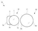
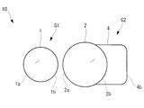
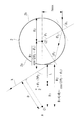
- FIG. 1 is an overall configuration diagram of an objective optical system according to an embodiment of the present invention.
- FIG. 4 is an overall configuration diagram of a modified example of the objective optical system in FIG. 1.
- FIG. 9 is an overall configuration diagram of another modification of the objective optical system in FIG. 1.
- FIG. 9 is an overall configuration diagram of another modification of the objective optical system in FIG. 1. It is a figure which shows the off-axis light whose principal ray is outward at the exit surface of the second group. It is a figure which shows the off-axis light whose principal ray is telecentric at the exit surface of the second group. It is a figure which shows the off-axis light whose principal ray is inward at the exit surface of the second group.
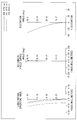
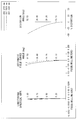
- FIG. 9 is a graph showing a relationship between a chief ray inclination and an aberration obtained by an optical simulation.
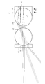
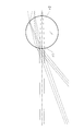
- FIG. 9 is a diagram illustrating a method for deriving conditional expression (1).
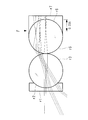
- FIG. 9 is a diagram illustrating a method for deriving conditional expression (2).
- FIG. 1 is an overall configuration diagram of an objective optical system according to a first embodiment.
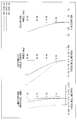
- FIG. 9 is an aberration diagram of the objective optical system of FIG. 8.
- FIG. 7 is an overall configuration diagram of an objective optical system according to a second embodiment.
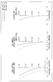
- FIG. 11 is an aberration diagram of the objective optical system of FIG. 10.
- FIG. 9 is an overall configuration diagram of an objective optical system according to a third embodiment.
- FIG. 13 is an aberration diagram of the objective optical system of FIG. 12.
- FIG. 14 is an overall configuration diagram of an objective optical system according to a fourth embodiment.
- FIG. 15 is an aberration diagram of the objective optical system of FIG. 14.
- FIG. 14 is an overall configuration diagram of an objective optical system according to a fifth embodiment.
- FIG. 14 is an overall configuration diagram of an objective optical system according to Example 6.
- FIG. 14 is an overall configuration diagram of an objective optical system according to a seventh embodiment.
- FIG. 19 is an aberration diagram of the objective optical system of FIG. 18.
- FIG. 2 is an overall configuration diagram of an objective optical system according to Comparative Example 1.
- 21 is an aberration diagram of the objective optical system of FIG. 20.
- FIG. 7 is an overall configuration diagram of an objective optical system according to Comparative Example 2.
- FIG. 23 is an aberration diagram of the objective optical system of FIG. 22.
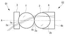
- the objective optical system 10 includes a first group G1 and a second group G2 arranged on the optical axis A in order from the object O side.
- the objective optical system 10 may further include an optical element having substantially no refractive power, such as a cover glass and a filter.
- the first group G1 includes a first spherical lens 1 and a first optical medium 3.
- the first spherical lens 1 has a lens surface 1a on the object O side and a lens surface 1b on the opposite side to the object O.
- the lens surfaces 1a and 1b are spherical surfaces having the same radius of curvature and a common center of curvature.
- the first optical medium 3 is arranged on the object O side of the first spherical lens 1.
- the first optical medium 3 is in close contact with the lens surface 1a over the entire optical path on the lens surface 1a through which light from the object O passes.
- the surface (object side surface) 3a on the object O side of the first optical medium 3 is a flat surface or a spherical surface having an arbitrary curvature.
- the second group G2 includes a second spherical lens 2 and a second optical medium 4.
- the second spherical lens 2 has a lens surface 2a on the object O side and a lens surface 2b on the opposite side to the object O.
- the lens surfaces 2a and 2b are spherical surfaces having the same radius of curvature and a common center of curvature.
- the second optical medium 4 is arranged on the side of the second spherical lens 2 opposite to the object O.
- the second optical medium 4 is in close contact with the lens surface 2b over the entire optical path on the lens surface 2b through which light from the object O passes.
- the surface (image side surface) 4b of the second optical medium 4 opposite to the object O is a flat surface or a spherical surface having an arbitrary curvature.
- the optical path between the lens surface 1b and the lens surface 2a is filled with air.
- the lens surface 1b and the lens surface 2a may be in contact with each other at one point on the optical axis A, or may be separated from each other.
- the light from the object O forms an image by transmitting through the first optical medium 3, the first spherical lens 1, the second spherical lens 2, and the second optical medium 4.
- the imaging position at this time may be inside the second spherical lens 2 or the second optical medium 4. In that case, the light flux after image formation will pass through the second spherical lens 2 and the second optical medium 4, or the second optical medium 4.
- the rear focal point of the objective optical system 10 (the rear focal point of the entire first group G1 and second group G2) is located on the opposite side of the lens surface 2a from the object O.
- the rear focal point is an image forming position when a parallel light beam enters the lens system.
- the first optical medium 3 and the second optical medium 4 are optically transparent liquids or optically transparent solids.
- the liquid is, for example, water or oil.
- the solid is, for example, plastic, glass or a coating.
- the optical media 3 and 4 have a refractive index larger than that of air. It is preferable that the optical media 3 and 4 be an optical adhesive or a resin from the viewpoint of ease of manufacture of each of the first group G1 and the second group G2.
- the optical media 3 and 4 are formed by curing a general-purpose optical adhesive on the lens surfaces 1a and 2b.
- the first spherical lens 1 and the second spherical lens 2 each have a positive refractive power. Therefore, light that has entered the objective optical system 10 from the object O can be condensed by the first spherical lens 1 and the second spherical lens 2, and an image I of the object O can be formed.
- the manufacturing technology of the steel ball for the bearing can be applied to the manufacture of the ball lenses 1 and 2, the manufacture and miniaturization of the ball lenses 1 and 2 are easy. Further, since the spherical lenses 1 and 2 are spherical, assembly is easy. Therefore, for example, there is an advantage that a small objective optical system 10 suitable for mounting on a distal end portion of a small-diameter endoscope can be easily manufactured. Further, the refraction angle of the light beam on the lens surface 1a is reduced by the first optical medium 3 in close contact with the lens surface 1a, as compared with the case where the first optical medium 3 is not present.
- the refraction angle of the light beam on the lens surface 2b is reduced by the second optical medium 4 that is in close contact with the lens surface 2b, as compared with the case where the second optical medium 4 does not exist. Accordingly, there is an advantage that the amount of aberration generated by the spherical lenses 1 and 2 is suppressed, and a high-quality image I with little aberration can be formed by the spherical lenses 1 and 2.
- the provision of the optical medium 3 weakens the positive refractive power of the first group G1 compared to the positive refractive power of the spherical lens 1 alone.
- the positive refractive power of the second group G2 is weaker than the positive refractive power of the spherical lens 2 alone.
- the use of the two spherical lenses 1 and 2 compensates for the weakening of the refractive power caused by the optical media 3 and 4, and is equal to or higher than the positive refractive power of the single spherical lens 1 or 2. Positive refractive power can be realized.
- a “spherical lens” is a lens in which a lens surface on the object side and a lens surface on the side opposite to the object have a same radius of curvature and have a common center of curvature. is there. Therefore, the “spherical lens” includes a lens whose surface other than the two lens surfaces on the object side and the side opposite to the object has a shape other than a spherical surface.
- both the first optical medium 3 and the second optical medium 4 are provided, but instead, as shown in FIGS. 2A and 2B, the first optical medium 3 and the second optical medium 4 are provided. Only one of the optical medium 3 and the second optical medium 4 may be provided. Even in a configuration in which one of the optical media 3 and 4 is omitted, the effect of reducing the refraction angle of the light beam on the lens surface 1a or the lens surface 2b can be obtained. Therefore, with the two spherical lenses 1 and 2 and the one optical medium 3 or 4, it is possible to achieve both a large refractive power and an angle of view and suppression of occurrence of aberration.
- the rear focal point F is preferably located inside the second spherical lens 2 as shown in FIG.
- the object side surface 3a and the lens are compared with the design in which the rear focal point F is located on the opposite side to the object O of the second spherical lens 2.
- the negative refractive power of the surface 1a decreases, and the maximum ray height of the marginal ray of each light beam decreases. Therefore, spherical aberration and chromatic aberration can be further reduced.
- the first and second spherical lenses 1 and 2 use the same. Dust and the like on the optical surface affect the formed object image at infinity, and the quality of the object image at infinity is reduced. Since the rear focal point F is located in the second spherical lens 2, the defocus on the optical surfaces 1 a, 1 b, 2 a, 2 b, 3 a, and 4 b in the optical path is not focused, and the influence of the debris and the like is eliminated. Can prevent the quality of the object image at infinity from deteriorating.
- n 1 is the refractive index of the first and second spherical lenses 1 and 2
- R 1 is the radius of the first and second spherical lenses 1 and 2
- n 3 is the first optical medium 3 Is the distance on the optical axis A between the lens surface 1b and the lens surface 2a.
- N (n 1 n 3 + n 1 -2n 3 ) / R 1 .
- Conditional expression (1) defines a condition that the rear focal point F is located inside the second spherical lens 2. That is, by designing so as to satisfy the conditional expression (1), the objective optical system 11 in which the rear focal point F is located in the second spherical lens 2 can be manufactured.
- the conditional expression (1) is rewritten as the following conditional expression (1 ′). 0 ⁇ ⁇ n 1 (2n 3 ⁇ n 1 ) ⁇ / ⁇ 2n 3 ⁇ (n 1 ⁇ 3n 3 ) (n 1 ⁇ 2) ⁇ ⁇ 2 (1 ′)
- the objective optical system 11 may satisfy the following conditional expression (2).
- R 1 is the radius of the first spherical lens 1
- R 2 is the radius of the second spherical lens 2
- L is the distance between the lens surface 1 b and the lens surface 2 a on the optical axis A
- n 2 is the refractive index of the second spherical lens 2
- n 4 is the refractive index of the second optical medium 4.
- Conditional expression (2) defines a condition that a ray parallel to the optical axis A at the maximum image height passes through the first group G1 and the second group G2 without being kicked. That is, by satisfying the conditional expression (2), the occurrence of vignetting in the first group G1 and the second group G2 can be prevented, and the field of view can be maximized.
- the positive chief ray inclination ⁇ means that the principal ray of the most off-axis light is outward (see FIG. 4A), and the negative chief ray inclination ⁇ is that the principal ray of the most off-axis light is inward (see FIG. 4A). 4C.).
- FIG. 5 shows the result of analyzing the relationship between the principal ray tilt angle ⁇ and the aberration by an optical simulation with respect to the objective optical system of Example 5 described later.
- ⁇ ⁇ 5 ° In the range of ⁇ ⁇ 5 °, almost no wavefront aberration occurs.
- the wavefront aberration increases as the chief ray inclination angle ⁇ increases.
- the chief ray inclination angle ⁇ As described above, by controlling the chief ray inclination angle ⁇ to 5 ° or less by the position of the brightness stop 6 arranged on the side opposite to the object O of the second group G2, the occurrence of aberration can be further suppressed. .
- the objective optical systems 10 and 11 including the aperture stop 6 can be suitably combined with an image sensor.
- the image sensor is arranged, for example, on the opposite side of the image transmission system 5 from the object O.
- the brightness of the image I captured by the image sensor can be appropriately adjusted by the brightness stop 6.
- an arbitrary device such as a lens, an aperture, a lens frame, or the like may be arranged on the opposite side of the image transmission system 5 from the object O.
- Conditional expression (1) is derived as follows. As shown in FIG. 6, paraxial ray tracing is performed.
- the rear focal point F is a position where the paraxial ray i incident parallel to the optical axis A crosses the optical axis A.
- the fact that the rear focal point F is located inside the second spherical lens 2 means that the paraxial ray j refracted on the lens surface 2a of the second spherical lens 2 has an optical axis A before the paraxial ray j reaches the lens surface 2b. Intersecting, that is, the distance X between the lens surface 2a and the rear focal point F is equivalent to satisfying the following expression (a).
- Conditional expression (2) is derived as follows. First, as shown in FIG. 7, h max is determined from the condition that the light beam k traveling from the image I to the object O passes through the lens surface 2a.
- reference numeral C1 indicates the center of the first spherical lens 1
- reference numeral C2 indicates the center of the second spherical lens 2.
- conditional expression (2) is derived from the expressions (f) and (g). However, the following expression is satisfied from Snell's law on the lens surfaces 2a and 2b.
- ⁇ 2 sin ⁇ 1 (1 / n 2 )
- r is the radius of curvature (mm)
- d is the surface interval (mm)
- Nd is the refractive index for the d-line
- vd is the Abbe number for the d-line
- OBJ is the object plane
- IMG is the image plane.
- S indicate the aperture stop.
- the aberration diagrams of the objective optical system according to each example show aberrations of an image formed by the first group and the second group.
- FIG. 8 shows the configuration of the objective optical system according to the first embodiment of the present invention.
- the objective optical system according to the present example includes a first spherical lens, a second spherical lens, a first optical medium, a second optical medium, and a brightness stop.
- illustration of the aperture stop is omitted.
- FIG. 9 shows an aberration diagram of the objective optical system of the present embodiment.
- FIG. 20 shows an objective optical system according to Comparative Example 1.
- the objective optical system of Comparative Example 1 includes a single spherical lens and a brightness stop. In FIG. 20, the illustration of the aperture stop is omitted.
- the lens data and various data of Comparative Example 1 are as follows.
- FIG. 21 shows an aberration diagram of the objective optical system of Comparative Example 1. As can be seen from the comparison between FIG. 9 and FIG. 21, the aberration of the objective optical system of Example 1 of the present invention, particularly the spherical aberration, the chromatic aberration and the field curvature, are significantly reduced as compared with the aberration of Comparative Example 1. ing.
- FIG. 22 shows an objective optical system according to Comparative Example 2.
- the objective optical system of Comparative Example 2 includes a single spherical lens, plano-convex lens, and aperture stop.
- the plano-convex lens has a role of correcting the aberration generated by the spherical lens.
- the illustration of the aperture stop is omitted.
- the lens data of the comparative example 2 is as follows, and the object-side numerical aperture is 0.018.
- An aberration diagram of the objective optical system of Comparative Example 2 is shown in FIG. As can be seen from the comparison between FIG. 9 and FIG.
- the aberration of the objective optical system of Example 1 of the present invention in particular, the spherical aberration, the chromatic aberration, and the field curvature are compared with those of the objective optical system of Comparative Example 2. It has been greatly reduced. That is, the effect of suppressing the aberration of the spherical lens by the first and second optical media is greater than the effect of correcting the aberration of the spherical lens by the plano-convex lens.
- FIG. 10 shows the configuration of the objective optical system according to the second embodiment of the present invention.
- the objective optical system according to the present example includes a first spherical lens, a second spherical lens, a first optical medium, a second optical medium, and a brightness stop.
- the illustration of the aperture stop is omitted.
- the first spherical lens and the second spherical lens have the same radius and are formed of the same material.
- the rear focal point F is located in the second spherical lens.
- the distance between the rear focal point F and the lens surface of the second spherical lens opposite to the object is 0.244 mm.
- FIG. 11 shows an aberration diagram of the objective optical system of the present embodiment. Compared with the first embodiment, the spherical aberration and the chromatic aberration of the objective optical system of the present embodiment are further reduced.
- FIG. 12 shows the configuration of the objective optical system according to the third embodiment of the present invention.
- the objective optical system according to the present example includes a first spherical lens, a second spherical lens, a first optical medium, a second optical medium, and a brightness stop.
- the illustration of the aperture stop is omitted.
- the first spherical lens and the second spherical lens have the same radius and are formed of the same material.
- the object side surface of the first optical medium is a flat surface perpendicular to the optical axis.
- the rear focal point F is located in the second spherical lens.
- the value of the middle side of the inequality expression of the conditional expression (1) is 1.456, and the objective optical system of the present embodiment satisfies the conditional expression (1).
- the distance between the rear focal point F and the lens surface of the second spherical lens opposite to the object is 0.268 mm.
- FIG. 13 shows an aberration diagram of the objective optical system of the present embodiment.
- FIG. 14 shows the configuration of the objective optical system according to the fourth embodiment of the present invention.
- the objective optical system according to the present example includes a first spherical lens, a second spherical lens, a first optical medium, a second optical medium, and a brightness stop.
- the illustration of the aperture stop is omitted.
- the first spherical lens and the second spherical lens have the same radius and are formed of the same material.
- the first spherical lens and the second spherical lens are in contact with each other at one point on the optical axis.
- the object side surface of the first optical medium is a flat surface perpendicular to the optical axis.
- the rear focal point F is located in the second spherical lens. Specifically, the value of the middle side of the inequality expression of the conditional expression (1 ′) is 1.52, and the objective optical system of the present embodiment satisfies the conditional expression (1 ′). The distance between the rear focal point F and the lens surface of the second spherical lens opposite to the object is 0.336 mm.
- FIG. 15 shows an aberration diagram of the objective optical system of the present embodiment.
- FIG. 16 shows the configuration of the objective optical system according to the fifth embodiment of the present invention.
- the objective optical system according to the present embodiment is an example in which an image transmission system including a combination of a plurality of lenses is combined with the objective optical system according to the fourth embodiment.
- the aperture stop is arranged in the image transmission system.
- FIG. 17 shows the configuration of the objective optical system according to the sixth embodiment of the present invention.
- the objective optical system according to the present embodiment is an example in which an image transmission system including a GRIN lens is combined with the objective optical system according to the second embodiment.
- the aperture stop is arranged in the image transmission system.
- FIG. 18 shows the configuration of the objective optical system according to Example 7 of the present invention.
- the objective optical system according to the present example includes a first spherical lens, a second spherical lens, a first optical medium, a second optical medium, and a brightness stop.
- An image transmission system may be further provided on the side of the second optical medium opposite to the object.
- the image side surface of the second optical medium is a flat surface perpendicular to the optical axis.
- FIG. 19 shows an aberration diagram of the objective optical system of the present embodiment.
- Lens data surface number rd Nd ⁇ d OBJ 1 10.0 1 0.1 0.1 1.561 35.4683 2 0.5 1.0 1.58913 61.13 3 -0.5 0.0 4 ⁇ 0.0 5 0.5 1.0 1.58913 61.13 6 -0.5 0.1 1.561 35.4683 7 ⁇ 1000 8S ⁇ -1000 9 ⁇ -0.2635 IMG 0.0 0.0
Landscapes
- Physics & Mathematics (AREA)
- Optics & Photonics (AREA)
- Life Sciences & Earth Sciences (AREA)
- Health & Medical Sciences (AREA)
- General Physics & Mathematics (AREA)
- Surgery (AREA)
- Public Health (AREA)
- Molecular Biology (AREA)
- Pathology (AREA)
- Radiology & Medical Imaging (AREA)
- Veterinary Medicine (AREA)
- Engineering & Computer Science (AREA)
- Biomedical Technology (AREA)
- Heart & Thoracic Surgery (AREA)
- Nuclear Medicine, Radiotherapy & Molecular Imaging (AREA)
- Animal Behavior & Ethology (AREA)
- Medical Informatics (AREA)
- General Health & Medical Sciences (AREA)
- Biophysics (AREA)
- Astronomy & Astrophysics (AREA)
- Lenses (AREA)
- Instruments For Viewing The Inside Of Hollow Bodies (AREA)
- Endoscopes (AREA)
Abstract
対物光学系(10)は、物体側から順に配列された第1の球レンズ(1)および第2の球レンズ(2)と、第1の光学媒体(3)および第2の光学媒体(4)のうち少なくとも一方とを備え、第1の光学媒体(3)が、第1の球レンズ(1)の物体側に配置された固体または液体であり、第1の球レンズ(1)の物体側の面(1a)上の光路の全域に密着し、第2の光学媒体(4)が、第2の球レンズ(2)の物体とは反対側に配置された固体または液体であり、第2の球レンズ(2)の物体とは反対側の面(2b)上の光路の全域に密着し、第1の球レンズ(1)と第2の球レンズ(2)との間の光路が、空気で満たされている。
Description
本発明は、対物光学系に関するものである。
従来、球レンズを備える対物光学系が知られている(例えば、特許文献1参照。)。球レンズは、形状が単純であるため、製造、組み立ておよび微小化が容易である。したがって、球レンズは、細径な内視鏡の対物光学系に好適である。
しかしながら、球レンズが発生させる収差は大きい。したがって、収差の少ない画像を得るためには、球レンズが発生させた収差を補正するための平凸レンズのような補正用光学部品が必要になるという不都合がある。
本発明は、上述した事情に鑑みてなされたものであって、球レンズによる収差の発生を抑制し、収差の少ない物体像を球レンズによって形成することができる対物光学系を提供することを目的とする。
本発明は、上述した事情に鑑みてなされたものであって、球レンズによる収差の発生を抑制し、収差の少ない物体像を球レンズによって形成することができる対物光学系を提供することを目的とする。
本発明の一態様は、物体側から順に配列された第1の球レンズおよび第2の球レンズと、第1の光学媒体および第2の光学媒体のうち少なくとも一方とを備え、前記第1の光学媒体が、前記第1の球レンズの前記物体側に配置された固体または液体であり、前記第1の球レンズの前記物体側の面上の光路の全域にわたって密着し、前記第2の光学媒体が、前記第2の球レンズの前記物体とは反対側に配置された固体または液体であり、前記第2の球レンズの前記物体とは反対側の面上の光路の全域にわたって密着し、前記第1の球レンズと前記第2の球レンズとの間の光路が、空気で満たされている対物光学系である。
本発明によれば、球レンズによる収差の発生を抑制し、収差の少ない物体像を球レンズによって形成することができるという効果を奏する。
以下に、本発明の一実施形態に係る対物光学系について図面を参照して説明する。
本実施形態に係る対物光学系10は、図1に示されるように、物体O側から順に光軸A上に配列された第1群G1および第2群G2を備えている。対物光学系10は、カバーガラスおよびフィルタのような、実質的に屈折力を有しない光学素子をさらに備えていてもよい。
本実施形態に係る対物光学系10は、図1に示されるように、物体O側から順に光軸A上に配列された第1群G1および第2群G2を備えている。対物光学系10は、カバーガラスおよびフィルタのような、実質的に屈折力を有しない光学素子をさらに備えていてもよい。
第1群G1は、第1の球レンズ1および第1の光学媒体3を備えている。
第1の球レンズ1は、物体O側のレンズ面1aと、物体Oとは反対側のレンズ面1bと、を有している。レンズ面1aおよびレンズ面1bは、相互に同一の曲率半径を有するとともに共通の曲率中心を有する球面である。
第1の光学媒体3は、第1の球レンズ1の物体O側に配置されている。第1の光学媒体3は、物体Oからの光が通過するレンズ面1a上の光路全域において、レンズ面1aと密着している。第1の光学媒体3の物体O側の面(物体側面)3aは、平坦面または任意の曲率を有する球面である。
第1の球レンズ1は、物体O側のレンズ面1aと、物体Oとは反対側のレンズ面1bと、を有している。レンズ面1aおよびレンズ面1bは、相互に同一の曲率半径を有するとともに共通の曲率中心を有する球面である。
第1の光学媒体3は、第1の球レンズ1の物体O側に配置されている。第1の光学媒体3は、物体Oからの光が通過するレンズ面1a上の光路全域において、レンズ面1aと密着している。第1の光学媒体3の物体O側の面(物体側面)3aは、平坦面または任意の曲率を有する球面である。
第2群G2は、第2の球レンズ2および第2の光学媒体4を備えている。
第2の球レンズ2は、物体O側のレンズ面2aと、物体Oとは反対側のレンズ面2bと、を有している。レンズ面2aおよびレンズ面2bは、相互に同一の曲率半径を有するとともに共通の曲率中心を有する球面である。
第2の光学媒体4は、第2の球レンズ2の物体Oとは反対側に配置されている。第2の光学媒体4は、物体Oからの光が通過するレンズ面2b上の光路全域において、レンズ面2bと密着している。第2の光学媒体4の物体Oとは反対側の面(像側面)4bは、平坦面または任意の曲率を有する球面である。
第2の球レンズ2は、物体O側のレンズ面2aと、物体Oとは反対側のレンズ面2bと、を有している。レンズ面2aおよびレンズ面2bは、相互に同一の曲率半径を有するとともに共通の曲率中心を有する球面である。
第2の光学媒体4は、第2の球レンズ2の物体Oとは反対側に配置されている。第2の光学媒体4は、物体Oからの光が通過するレンズ面2b上の光路全域において、レンズ面2bと密着している。第2の光学媒体4の物体Oとは反対側の面(像側面)4bは、平坦面または任意の曲率を有する球面である。
レンズ面1bとレンズ面2aとの間の光路は、空気で満たされている。レンズ面1bとレンズ面2aは、光軸A上で1点で相互に接触していてもよく、相互に離間していてもよい。
物体Oからの光は、第1の光学媒体3、第1の球レンズ1、第2の球レンズ2および第2の光学媒体4を透過することによって結像される。このときの結像位置は、第2の球レンズ2または第2の光学媒体4の内部になる場合もある。その場合には、結像後の光束が第2の球レンズ2および第2の光学媒体4、または第2の光学媒体4を透過することになる。対物光学系10の後側焦点(第1群G1および第2群G2全体の後側焦点)は、レンズ面2aの物体Oとは反対側に位置している。後側焦点は、レンズ系に平行光束が入射したときの結像位置である。
物体Oからの光は、第1の光学媒体3、第1の球レンズ1、第2の球レンズ2および第2の光学媒体4を透過することによって結像される。このときの結像位置は、第2の球レンズ2または第2の光学媒体4の内部になる場合もある。その場合には、結像後の光束が第2の球レンズ2および第2の光学媒体4、または第2の光学媒体4を透過することになる。対物光学系10の後側焦点(第1群G1および第2群G2全体の後側焦点)は、レンズ面2aの物体Oとは反対側に位置している。後側焦点は、レンズ系に平行光束が入射したときの結像位置である。
第1の光学媒体3および第2の光学媒体4は、光学的に透明な液体、または、光学的に透明な固体である。液体は、例えば、水または油である。固体は、例えば、プラスチック、ガラスまたはコーティング材である。光学媒体3,4は、空気の屈折率よりも大きな屈折率を有する。第1群G1および第2群G2の各々の製造の容易性の観点から、光学媒体3,4は、光学接着剤または樹脂であることが好ましい。例えば、光学媒体3,4は、汎用の光学接着剤をレンズ面1a,2b上で硬化させることによって形成される。
次に、このように構成された対物光学系10の作用について説明する。
第1の球レンズ1および第2の球レンズ2は、正の屈折力をそれぞれ有する。したがって、物体Oから対物光学系10に入射した光を、第1の球レンズ1および第2の球レンズ2によって集光させ、物体Oの像Iを形成することができる。
第1の球レンズ1および第2の球レンズ2は、正の屈折力をそれぞれ有する。したがって、物体Oから対物光学系10に入射した光を、第1の球レンズ1および第2の球レンズ2によって集光させ、物体Oの像Iを形成することができる。
この場合に、球レンズ1,2の製造にはベアリング用鋼球の製造技術を応用することができるため、球レンズ1,2は、製造および微小化が容易である。また、球レンズ1,2は、球体であるため組み立てが容易である。したがって、例えば細径の内視鏡の先端部への搭載に好適な、小型の対物光学系10を容易に製造することができるという利点がある。
また、レンズ面1aに密着した第1の光学媒体3によって、レンズ面1aでの光線の屈折角が、第1の光学媒体3が存在しない場合と比較して低減される。同様に、レンズ面2bに密着した第2の光学媒体4によって、レンズ面2bでの光線の屈折角が、第2の光学媒体4が存在しない場合と比較して低減される。これにより、球レンズ1,2による収差の発生量を抑制し、収差の少ない高品質な像Iを球レンズ1,2によって形成することができるという利点がある。
また、レンズ面1aに密着した第1の光学媒体3によって、レンズ面1aでの光線の屈折角が、第1の光学媒体3が存在しない場合と比較して低減される。同様に、レンズ面2bに密着した第2の光学媒体4によって、レンズ面2bでの光線の屈折角が、第2の光学媒体4が存在しない場合と比較して低減される。これにより、球レンズ1,2による収差の発生量を抑制し、収差の少ない高品質な像Iを球レンズ1,2によって形成することができるという利点がある。
また、光学媒体3が設けられていることによって、第1群G1の正の屈折力は、球レンズ1単体の正の屈折力と比較して弱まる。同様に、光学媒体4が設けられていることによって、第2群G2の正の屈折力は、球レンズ2単体の正の屈折力と比較して弱まる。本実施形態によれば、2つの球レンズ1,2を用いることによって、光学媒体3,4に因る屈折力の弱まりを補い、単体の球レンズ1または2の正の屈折力と同等以上の正の屈折力を実現することができる。
また、2つの球レンズ1,2が設けられていることによって、単一の球レンズからなる対物光学系の画角と同等以上の画角を確保することができるという利点がある。例えば、球レンズ2および光学媒体4のみからなる対物光学系の画角は、球レンズ2のみからなる対物光学系の画角に比べて小さくなる。このような光学媒体3,4に因る画角の減少を、2つの球レンズ1,2によって補うことができる。
なお、本明細書において、「球レンズ」とは、物体側のレンズ面および物体とは反対側のレンズ面が、相互に同一の曲率半径を有するとともに共通の曲率中心を有する球面であるレンズである。したがって、「球レンズ」は、物体側および物体とは反対側の2つのレンズ面以外の面が球面以外の形状であるレンズを含む。
本実施形態においては、第1の光学媒体3および第2の光学媒体4の両方が設けられていることとしたが、これに代えて、図2Aおよび図2Bに示されるように、第1の光学媒体3および第2の光学媒体4のいずれか一方のみが設けられていてもよい。
光学媒体3,4のうちいずれか一方を省いた構成においても、レンズ面1aまたはレンズ面2bでの光線の屈折角の低減効果を得られる。したがって、2つの球レンズ1,2および1つの光学媒体3または4によって、大きな屈折力および画角と、収差の発生の抑制とを両立することができる。
光学媒体3,4のうちいずれか一方を省いた構成においても、レンズ面1aまたはレンズ面2bでの光線の屈折角の低減効果を得られる。したがって、2つの球レンズ1,2および1つの光学媒体3または4によって、大きな屈折力および画角と、収差の発生の抑制とを両立することができる。
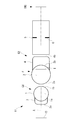
本実施形態において、図3に示されるように、第2の球レンズ2の物体Oとは反対側に配置され、第1および第2の球レンズ1,2によって形成された像Iを伝送する像伝送系5をさらに備えていてもよい。
像伝送系5は、複数のレンズの組み合わせ、または、屈折率分布型(GRIN)レンズである。像伝送系5を設けることによって、第1群G1および第2群G2によって形成された像Iを所望の位置の像面IMGに再結像させることができる。
像伝送系5は、複数のレンズの組み合わせ、または、屈折率分布型(GRIN)レンズである。像伝送系5を設けることによって、第1群G1および第2群G2によって形成された像Iを所望の位置の像面IMGに再結像させることができる。
像伝送系5を備える対物光学系11において、後側焦点Fは、図3に示されるように、第2の球レンズ2の内部に位置していることが好ましい。後側焦点Fが第2の球レンズ2内に位置する設計において、後側焦点Fが第2の球レンズ2の物体Oとは反対側に位置する設計と比較して、物体側面3aおよびレンズ面1aの負の屈折力は小さくなり、各光束のマージナル光線の最大光線高さが低くなる。したがって、球面収差および色収差をさらに低減することができる。また、後側焦点が球レンズ1,2または光学媒体3,4の光学面1a,1b,2a,2b,3a,4bに一致している場合、第1および第2の球レンズ1,2によって形成される無限遠の物体像に光学面上の塵等が影響を与え、無限遠の物体像の品質の低下を招く。後側焦点Fが第2の球レンズ2内に位置することによって、光路中の光学面1a,1b,2a,2b,3a,4b上のゴミ等に焦点が合うことがなく、ゴミ等の影響による無限遠の物体像の品質の低下を防ぐことができる。
第1の球レンズ1および第2の球レンズ2が、相互に同一の半径を有するとともに相互に同一の材料から形成され、第1の光学媒体3の物体側面3aが光軸Aに垂直な平坦面である場合、対物光学系11は、下記条件式(1)を満たす。
0≦{n1(2n3-n1)-n1LN}/{2n3-(n1-3n3)(n1-2)-(n1-1)LN}≦2 …(1)
ここで、n1は、第1および第2の球レンズ1,2の屈折率、R1は、第1および第2の球レンズ1,2の半径、n3は、第1の光学媒体3の屈折率、Lは、レンズ面1bとレンズ面2aとの間の光軸A上の間隔である。N=(n1n3+n1-2n3)/R1である。
0≦{n1(2n3-n1)-n1LN}/{2n3-(n1-3n3)(n1-2)-(n1-1)LN}≦2 …(1)
ここで、n1は、第1および第2の球レンズ1,2の屈折率、R1は、第1および第2の球レンズ1,2の半径、n3は、第1の光学媒体3の屈折率、Lは、レンズ面1bとレンズ面2aとの間の光軸A上の間隔である。N=(n1n3+n1-2n3)/R1である。
条件式(1)は、後側焦点Fが第2の球レンズ2の内部に位置する条件を規定している。すなわち、条件式(1)を満たすように設計することによって、後側焦点Fが第2の球レンズ2内に位置する対物光学系11を製造することができる。
レンズ面1bとレンズ面2aが光軸A上で相互に接している(すなわち、L=0)場合、条件式(1)は、下記条件式(1’)のように書き替えられる。
0≦{n1(2n3-n1)}/{2n3-(n1-3n3)(n1-2)}≦2 …(1’)
レンズ面1bとレンズ面2aが光軸A上で相互に接している(すなわち、L=0)場合、条件式(1)は、下記条件式(1’)のように書き替えられる。
0≦{n1(2n3-n1)}/{2n3-(n1-3n3)(n1-2)}≦2 …(1’)
後側焦点Fが第2の球レンズ2内に位置し像側面4bが光軸Aに垂直な平坦面である場合、対物光学系11は、下記条件式(2)を満たしていてもよい。
1≦(R1+R2)*[{1/cos(2θ2-θ1)}―1]/L …(2)
ここで、R1は、第1の球レンズ1の半径、R2は、第2の球レンズ2の半径、Lは、レンズ面1bとレンズ面2aとの間の光軸A上の間隔、n2は、第2の球レンズ2の屈折率、n4は、第2の光学媒体4の屈折率である。θ1=sin-1(1/n4)、θ2=sin-1(1/n2)である。
1≦(R1+R2)*[{1/cos(2θ2-θ1)}―1]/L …(2)
ここで、R1は、第1の球レンズ1の半径、R2は、第2の球レンズ2の半径、Lは、レンズ面1bとレンズ面2aとの間の光軸A上の間隔、n2は、第2の球レンズ2の屈折率、n4は、第2の光学媒体4の屈折率である。θ1=sin-1(1/n4)、θ2=sin-1(1/n2)である。
条件式(2)は、最大像高における光軸Aに平行な光線が、蹴られることなく第1群G1および第2群G2を通過する条件を規定している。すなわち、条件式(2)を満たすことによって、第1群G1および第2群G2におけるケラレの発生を防ぎ、視野を最大限確保することができる。
本実施形態においては、対物光学系10,11が、光路中の任意の位置に明るさ絞り6をさらに備えていてもよい。明るさ絞り6によって、物体像Iの明るさを適切に制御することができる。
明るさ絞り6は、第2群G2の物体Oとは反対側に配置されていることが好ましく、例えば、図3に示されるように、像伝送系5内に配置される。
明るさ絞り6は、第2群G2の物体Oとは反対側に配置されていることが好ましく、例えば、図3に示されるように、像伝送系5内に配置される。
収差の発生量は、第2の球レンズ2のレンズ面2bにおける最軸外光の主光線の光軸に対する傾角に依存する。この傾角は、対物光学系10,11内における明るさ絞り6の位置によって制御される。明るさ絞り6は、図4Aおよび図4Bに示されるように、第2群G2の光線の射出面(レンズ面2bまたは像側面4b)での軸外光の主光線が外向き、テレセントリックまたは略テレセントリックになる位置に配置される。
具体的には、明るさ絞り6は、主光線傾角θが5°以下になる位置に配置される。主光線傾角θは、最軸外光の主光線の光軸Aに対する傾角である。正の主光線傾角θは、最軸外光の主光線が外向き(図4A参照。)であることを意味し、負の主光線傾角θは、最軸外光の主光線が内向き(図4C参照。)であることを意味する。
具体的には、明るさ絞り6は、主光線傾角θが5°以下になる位置に配置される。主光線傾角θは、最軸外光の主光線の光軸Aに対する傾角である。正の主光線傾角θは、最軸外光の主光線が外向き(図4A参照。)であることを意味し、負の主光線傾角θは、最軸外光の主光線が内向き(図4C参照。)であることを意味する。
図5は、後述する実施例5の対物光学系について、主光線傾角θと収差との関係を光学シミュレーションによって解析した結果を示している。θ≦5°の範囲では、波面収差はほとんど発生しない。一方、θ>5°の範囲では、主光線傾角θが大きい程、波面収差が大きくなる。
このように、第2群G2の物体Oとは反対側に配置された明るさ絞り6の位置によって主光線傾角θを5°以下に制御することで、収差の発生をさらに抑制することができる。
このように、第2群G2の物体Oとは反対側に配置された明るさ絞り6の位置によって主光線傾角θを5°以下に制御することで、収差の発生をさらに抑制することができる。
明るさ絞り6を備える対物光学系10,11は、撮像素子と好適に組み合わせることができる。撮像素子は、例えば、像伝送系5の物体Oとは反対側に配置される。明るさ絞り6によって、撮像素子によって撮影される像Iの明るさを適切に調整することができる。撮像素子に代えて、レンズ、絞り、鏡枠等の任意の素子が、像伝送系5の物体Oとは反対側に配置されてもよい。
次に、条件式(1)および(2)の導出方法について、図6および図7を参照して説明する。
条件式(1)は、以下のようにして導かれる。
図6に示されるように、近軸光線追跡を実行する。後側焦点Fは、光軸Aと平行に入射した近軸光線iが光軸Aと交わる位置である。後側焦点Fが第2の球レンズ2の内部に位置するということは、第2の球レンズ2のレンズ面2aにおいて屈折した近軸光線jがレンズ面2bに到達する前に光軸Aと交わること、すなわち、レンズ面2aと後側焦点Fとの間の距離Xが、下式(a)を満たすことと等価である。
0≦X≦2×R1 …(a)
各面3a,1a,1b,2aでの屈折マトリクスR1,R2,R3,R4および伝達マトリクスT1,T2,T3は、以下の通りである。
条件式(1)は、以下のようにして導かれる。
図6に示されるように、近軸光線追跡を実行する。後側焦点Fは、光軸Aと平行に入射した近軸光線iが光軸Aと交わる位置である。後側焦点Fが第2の球レンズ2の内部に位置するということは、第2の球レンズ2のレンズ面2aにおいて屈折した近軸光線jがレンズ面2bに到達する前に光軸Aと交わること、すなわち、レンズ面2aと後側焦点Fとの間の距離Xが、下式(a)を満たすことと等価である。
0≦X≦2×R1 …(a)
各面3a,1a,1b,2aでの屈折マトリクスR1,R2,R3,R4および伝達マトリクスT1,T2,T3は、以下の通りである。
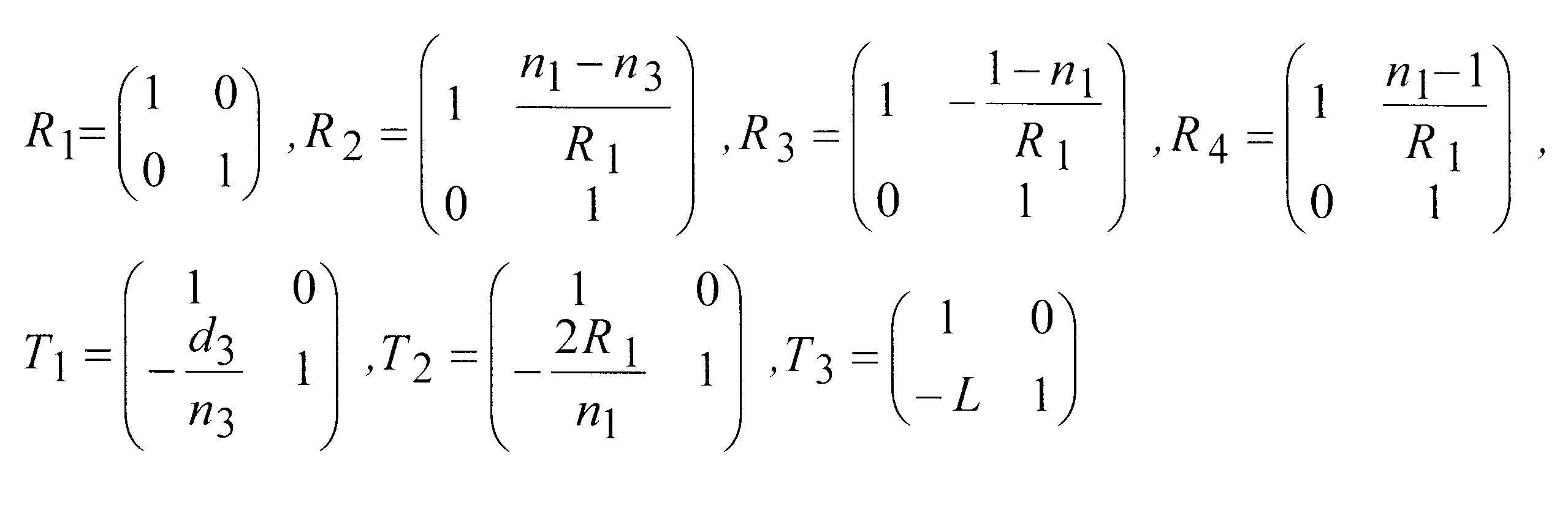
物体側面3aに入射した近軸光線i(h1,0)が、レンズ面2aにおける屈折によって光線j(h4,α4)になる場合、下式(b)が成り立つ。

式(b)からα4,h4を求めると、X=h4/(α4/h1)が得られる。Xと式(a)から、条件式(1)が導かれる。
条件式(2)は、以下のように導かれる。
まず、図7に示されるように、像Iから物体Oへ向かう光線kがレンズ面2aを通過する条件から、hmaxを求める。図7において、符号C1は、第1の球レンズ1の中心を示し、符号C2は、第2の球レンズ2の中心を示している。
まず、図7に示されるように、像Iから物体Oへ向かう光線kがレンズ面2aを通過する条件から、hmaxを求める。図7において、符号C1は、第1の球レンズ1の中心を示し、符号C2は、第2の球レンズ2の中心を示している。
光線kがレンズ面2aを通過するためには、スネルの法則に基づき、下式を満たす必要がある。
n2sinθ2≦1 …(c)
また、レンズ面2bでのスネルの法則から下式(d)が成立する。
n4sinθ1=n2sinθ2 …(d)
ここで、sinθ1=h/R2…(e)である。式(c),(d),(e)から、1≦R2/hn4が得られ、これから、hmax=R2/h4と算出される。
n2sinθ2≦1 …(c)
また、レンズ面2bでのスネルの法則から下式(d)が成立する。
n4sinθ1=n2sinθ2 …(d)
ここで、sinθ1=h/R2…(e)である。式(c),(d),(e)から、1≦R2/hn4が得られ、これから、hmax=R2/h4と算出される。
次に、レンズ面2aの縁を通過した光線が第1の球レンズ1と交わる条件について考える。この条件は、レンズ面2aの縁を通過した光線が、第1の球レンズ1および屈折率n3の物質を通過する条件と略等価である。
上記条件において、図7のDは、D≦R1…(f)を満たす。
図7の幾何学的な関係から、Dは、下式(g)の通り表される。
上記条件において、図7のDは、D≦R1…(f)を満たす。
図7の幾何学的な関係から、Dは、下式(g)の通り表される。
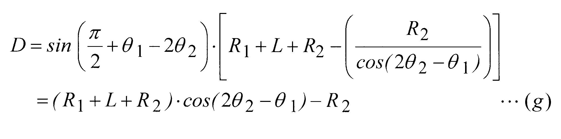
式(f)および式(g)から、条件式(2)が導かれる。ただし、レンズ面2aおよびレンズ面2bにおけるスネルの法則から、下式を満たす。
θ1=sin-1(hmax/R2)=sin-1(1/n4)
θ2=sin-1(1/n2)
θ1=sin-1(hmax/R2)=sin-1(1/n4)
θ2=sin-1(1/n2)
次に、本実施形態に係る対物光学系10,11の実施例について説明する。
各実施例のレンズデータにおいて、rは曲率半径(mm)、dは面間隔(mm)、Ndはd線に対する屈折率、νdはd線に対するアッべ数、OBJは物体面、IMGは像面、Sは明るさ絞りを示している。各実施例に係る対物光学系の収差図は、第1群および第2群によって形成される像の収差を示している。
各実施例のレンズデータにおいて、rは曲率半径(mm)、dは面間隔(mm)、Ndはd線に対する屈折率、νdはd線に対するアッべ数、OBJは物体面、IMGは像面、Sは明るさ絞りを示している。各実施例に係る対物光学系の収差図は、第1群および第2群によって形成される像の収差を示している。
(実施例1)
本発明の実施例1に係る対物光学系の構成を図8に示す。本実施例に係る対物光学系は、第1の球レンズ、第2の球レンズ、第1の光学媒体、第2の光学媒体、および明るさ絞りから構成されている。図8において、明るさ絞りの図示は省略されている。
本実施例の対物光学系の収差図を図9に示す。
本発明の実施例1に係る対物光学系の構成を図8に示す。本実施例に係る対物光学系は、第1の球レンズ、第2の球レンズ、第1の光学媒体、第2の光学媒体、および明るさ絞りから構成されている。図8において、明るさ絞りの図示は省略されている。
本実施例の対物光学系の収差図を図9に示す。
レンズデータ
面番号 r d Nd νd
OBJ ∞ 10
1 ∞ 0.0
2 ∞ 0.0
3 -0.41242 0.05 1.561 35.4683
4 0.5 1.0 1.48749 70.4058
5 -0.5 0.0
6 ∞ 0.1
7 0.5 1.0 1.510158 58.9349
8 -0.5 0.05 1.561 35.4683
9 -0.50945 0.0
10 ∞ 0.2
11 ∞ 1000
12S ∞ -1000
13 ∞ -0.1
IMG ∞ 0.0
面番号 r d Nd νd
OBJ ∞ 10
1 ∞ 0.0
2 ∞ 0.0
3 -0.41242 0.05 1.561 35.4683
4 0.5 1.0 1.48749 70.4058
5 -0.5 0.0
6 ∞ 0.1
7 0.5 1.0 1.510158 58.9349
8 -0.5 0.05 1.561 35.4683
9 -0.50945 0.0
10 ∞ 0.2
11 ∞ 1000
12S ∞ -1000
13 ∞ -0.1
IMG ∞ 0.0
各種データ
像側開口数 0.1
焦点距離 0.35mm
倍率 -0.034
半画角 40.0°
像高 0.18mm
像側開口数 0.1
焦点距離 0.35mm
倍率 -0.034
半画角 40.0°
像高 0.18mm
図20に、比較例1に係る対物光学系を示す。比較例1の対物光学系は、単一の球レンズおよび明るさ絞りから構成されている。図20において、明るさ絞りの図示は省略されている。比較例1のレンズデータおよび各種データは、以下の通りである。比較例1の対物光学系の収差図を図21に示す。
図9と図21との比較から分かるように、本発明の実施例1の対物光学系の収差、特に球面収差、色収差および像面湾曲は、比較例1の収差と比較して大幅に低減されている。
図9と図21との比較から分かるように、本発明の実施例1の対物光学系の収差、特に球面収差、色収差および像面湾曲は、比較例1の収差と比較して大幅に低減されている。
レンズデータ
面番号 r d Nd νd
OBJ ∞ 10
1 0.5 1.0 1.5168 64.1673
2 -0.5 0.0
3 ∞ 0.0
4 ∞ 1000
5S ∞ -1000
6 ∞ 0.2889
IMG ∞ 0.0
面番号 r d Nd νd
OBJ ∞ 10
1 0.5 1.0 1.5168 64.1673
2 -0.5 0.0
3 ∞ 0.0
4 ∞ 1000
5S ∞ -1000
6 ∞ 0.2889
IMG ∞ 0.0
各種データ
像側開口数 0.1
焦点距離 0.73mm
倍率 -0.075
半画角 40.0°
像高 0.38mm
像側開口数 0.1
焦点距離 0.73mm
倍率 -0.075
半画角 40.0°
像高 0.38mm
図22に、比較例2に係る対物光学系を示す。比較例2の対物光学系は、単一の球レンズ、平凸レンズおよび明るさ絞りから構成されている。平凸レンズは、球レンズが発生させた収差を補正する役割を担う。図22において、明るさ絞りの図示は省略されている。比較例2のレンズデータは、以下の通りであり、物体側開口数は0.018である。比較例2の対物光学系の収差図を図23に示す。
図9と図23との比較から分かるように、本発明の実施例1の対物光学系の収差、特に球面収差、色収差および像面湾曲は、比較例2の対物光学系の収差と比較して大幅に低減されている。すなわち、第1および第2の光学媒体による球レンズの収差の抑制効果は、平凸レンズによる球レンズの収差の補正効果よりも大きい。
図9と図23との比較から分かるように、本発明の実施例1の対物光学系の収差、特に球面収差、色収差および像面湾曲は、比較例2の対物光学系の収差と比較して大幅に低減されている。すなわち、第1および第2の光学媒体による球レンズの収差の抑制効果は、平凸レンズによる球レンズの収差の補正効果よりも大きい。
レンズデータ
面番号 r d Nd νd
OBJ ∞ 10
1S ∞ 0.0
2 1.5 3.0 1.561 35.4683
3 -1.5 0.0
4 ∞ 3.2907
5 5.168 2.0 1.561 35.4683
6 ∞ 0.0
7 ∞ 100
8 19.7838 2.0 1.4927 69.82
9 ∞ 63.3977
IMG ∞ 0.0
面番号 r d Nd νd
OBJ ∞ 10
1S ∞ 0.0
2 1.5 3.0 1.561 35.4683
3 -1.5 0.0
4 ∞ 3.2907
5 5.168 2.0 1.561 35.4683
6 ∞ 0.0
7 ∞ 100
8 19.7838 2.0 1.4927 69.82
9 ∞ 63.3977
IMG ∞ 0.0
(実施例2)
本発明の実施例2に係る対物光学系の構成を図10に示す。本実施例に係る対物光学系は、第1の球レンズ、第2の球レンズ、第1の光学媒体、第2の光学媒体、および明るさ絞りから構成されている。図10において、明るさ絞りの図示は省略されている。
第1の球レンズおよび第2の球レンズは、同一の半径を有するとともに同一の材質から形成されている。後側焦点Fは、第2の球レンズ内に位置する。後側焦点Fと、第2の球レンズの物体とは反対側のレンズ面と、の間の距離は、0.244mmである。
本実施例の対物光学系の収差図を図11に示す。実施例1と比較して、本実施例の対物光学系の球面収差および色収差はさらに低減されている。
本発明の実施例2に係る対物光学系の構成を図10に示す。本実施例に係る対物光学系は、第1の球レンズ、第2の球レンズ、第1の光学媒体、第2の光学媒体、および明るさ絞りから構成されている。図10において、明るさ絞りの図示は省略されている。
第1の球レンズおよび第2の球レンズは、同一の半径を有するとともに同一の材質から形成されている。後側焦点Fは、第2の球レンズ内に位置する。後側焦点Fと、第2の球レンズの物体とは反対側のレンズ面と、の間の距離は、0.244mmである。
本実施例の対物光学系の収差図を図11に示す。実施例1と比較して、本実施例の対物光学系の球面収差および色収差はさらに低減されている。
レンズデータ
面番号 r d Nd νd
OBJ ∞ 10
1 -7.61988 0.1 1.561 35.4683
2 0.5 1.0 1.5168 64.1673
3 -0.5 0.0
4 ∞ 0.1
5 0.5 1.0 1.5168 64.1673
6 -0.5 0.1 1.561 35.4683
7 ∞ 1000
8S ∞ -1000
9 ∞ -0.2
IMG ∞ 0.0
面番号 r d Nd νd
OBJ ∞ 10
1 -7.61988 0.1 1.561 35.4683
2 0.5 1.0 1.5168 64.1673
3 -0.5 0.0
4 ∞ 0.1
5 0.5 1.0 1.5168 64.1673
6 -0.5 0.1 1.561 35.4683
7 ∞ 1000
8S ∞ -1000
9 ∞ -0.2
IMG ∞ 0.0
各種データ
像側開口数 0.1
焦点距離 0.48mm
倍率 -0.047
半画角 40.0°
像高 0.28mm
像側開口数 0.1
焦点距離 0.48mm
倍率 -0.047
半画角 40.0°
像高 0.28mm
(実施例3)
本発明の実施例3に係る対物光学系の構成を図12に示す。本実施例に係る対物光学系は、第1の球レンズ、第2の球レンズ、第1の光学媒体、第2の光学媒体、および明るさ絞りから構成されている。図12において、明るさ絞りの図示は省略されている。
第1の球レンズおよび第2の球レンズは、同一の半径を有するとともに同一の材質から形成されている。第1の光学媒体の物体側面は、光軸に垂直な平坦面である。後側焦点Fは、第2の球レンズ内に位置する。具体的には、条件式(1)の不等式の中辺の値は、1.456であり、本実施例の対物光学系は条件式(1)を満たす。後側焦点Fと、第2の球レンズの物体とは反対側のレンズ面と、の間の距離は、0.268mmである。
本実施例の対物光学系の収差図を図13に示す。
本発明の実施例3に係る対物光学系の構成を図12に示す。本実施例に係る対物光学系は、第1の球レンズ、第2の球レンズ、第1の光学媒体、第2の光学媒体、および明るさ絞りから構成されている。図12において、明るさ絞りの図示は省略されている。
第1の球レンズおよび第2の球レンズは、同一の半径を有するとともに同一の材質から形成されている。第1の光学媒体の物体側面は、光軸に垂直な平坦面である。後側焦点Fは、第2の球レンズ内に位置する。具体的には、条件式(1)の不等式の中辺の値は、1.456であり、本実施例の対物光学系は条件式(1)を満たす。後側焦点Fと、第2の球レンズの物体とは反対側のレンズ面と、の間の距離は、0.268mmである。
本実施例の対物光学系の収差図を図13に示す。
レンズデータ
面番号 r d Nd νd
OBJ ∞ 10
1 ∞ 0.1 1.561 35.4683
2 0.5 1.0 1.5168 64.1673
3 -0.5 0.0
4 ∞ 0.1
5 0.5 1.0 1.5168 64.1673
6 -0.5 0.1 1.561 35.4683
7 ∞ 1000
8S ∞ -1000
9 ∞ -0.2168
IMG ∞ 0.0
面番号 r d Nd νd
OBJ ∞ 10
1 ∞ 0.1 1.561 35.4683
2 0.5 1.0 1.5168 64.1673
3 -0.5 0.0
4 ∞ 0.1
5 0.5 1.0 1.5168 64.1673
6 -0.5 0.1 1.561 35.4683
7 ∞ 1000
8S ∞ -1000
9 ∞ -0.2168
IMG ∞ 0.0
各種データ
像側開口数 0.1
焦点距離 0.49mm
倍率 -0.048
半画角 40.0°
像高 0.28mm
像側開口数 0.1
焦点距離 0.49mm
倍率 -0.048
半画角 40.0°
像高 0.28mm
(実施例4)
本発明の実施例4に係る対物光学系の構成を図14に示す。本実施例に係る対物光学系は、第1の球レンズ、第2の球レンズ、第1の光学媒体、第2の光学媒体、および明るさ絞りから構成されている。図14において、明るさ絞りの図示は省略されている。
第1の球レンズおよび第2の球レンズは、同一の半径を有するとともに同一の材質から形成されている。第1の球レンズおよび第2の球レンズは、光軸上の一点において相互に接触している。第1の光学媒体の物体側面は、光軸に垂直な平坦面である。後側焦点Fは、第2の球レンズ内に位置する。具体的には、条件式(1’)の不等式の中辺の値は、1.52であり、本実施例の対物光学系は条件式(1’)を満たす。後側焦点Fと、第2の球レンズの物体とは反対側のレンズ面と、の間の距離は、0.336mmである。
本実施例の対物光学系の収差図を図15に示す。
本発明の実施例4に係る対物光学系の構成を図14に示す。本実施例に係る対物光学系は、第1の球レンズ、第2の球レンズ、第1の光学媒体、第2の光学媒体、および明るさ絞りから構成されている。図14において、明るさ絞りの図示は省略されている。
第1の球レンズおよび第2の球レンズは、同一の半径を有するとともに同一の材質から形成されている。第1の球レンズおよび第2の球レンズは、光軸上の一点において相互に接触している。第1の光学媒体の物体側面は、光軸に垂直な平坦面である。後側焦点Fは、第2の球レンズ内に位置する。具体的には、条件式(1’)の不等式の中辺の値は、1.52であり、本実施例の対物光学系は条件式(1’)を満たす。後側焦点Fと、第2の球レンズの物体とは反対側のレンズ面と、の間の距離は、0.336mmである。
本実施例の対物光学系の収差図を図15に示す。
レンズデータ
面番号 r d Nd νd
OBJ ∞ 10
1 ∞ 0.1 1.561 35.4683
2 0.5 1.0 1.58913 61.13
3 -0.5 0.0
4 ∞ 0.0
5 0.5 1.0 1.58913 61.13
6 -0.5 0.1 1.561 35.4683
7 ∞ 1000
8S ∞ -1000
9 ∞ -0.2635
IMG ∞ 0.0
面番号 r d Nd νd
OBJ ∞ 10
1 ∞ 0.1 1.561 35.4683
2 0.5 1.0 1.58913 61.13
3 -0.5 0.0
4 ∞ 0.0
5 0.5 1.0 1.58913 61.13
6 -0.5 0.1 1.561 35.4683
7 ∞ 1000
8S ∞ -1000
9 ∞ -0.2635
IMG ∞ 0.0
各種データ
像側開口数 0.1
焦点距離 0.43mm
倍率 -0.042
半画角 52.5°
像高 0.3025mm
像側開口数 0.1
焦点距離 0.43mm
倍率 -0.042
半画角 52.5°
像高 0.3025mm
(実施例5)
本発明の実施例5に係る対物光学系の構成を図16に示す。本実施例に係る対物光学系は、実施例4の対物光学系に、複数のレンズの組み合わせからなる像伝送系を組み合わせた例である。明るさ絞りは、像伝送系内に配置されている。
本発明の実施例5に係る対物光学系の構成を図16に示す。本実施例に係る対物光学系は、実施例4の対物光学系に、複数のレンズの組み合わせからなる像伝送系を組み合わせた例である。明るさ絞りは、像伝送系内に配置されている。
レンズデータ
面番号 r d Nd νd
OBJ ∞ 10
1 ∞ 0.2 1.561 35.4683
2 1.0 2.0 1.58913 61.13
3 -1.0 0.0
4 ∞ 0.1
5 1.0 2.0 1.58913 61.13
6 -1.0 0.2 1.561 35.4683
7 ∞ 0.56
8 1.8288 1.1653 1.9020 25.1014
9 1.1556 1.4021
10 1.6464 0.7648 1.84139 24.5591
11 0.9995 2.8012 1.5588 62.5585
12 -1.0476 0.5968 1.647689 33.8482
13 6.9284 1.1787
14 -115.428 2.07 1.71736 29.6201
15 -4.1677 0.1718
16S ∞ 0.1718
17 4.1677 2.07 1.71736 29.6201
18 115.4278 1.1787
19 -6.9284 0.5968 1.647689 33.8482
20 1.0476 2.8012 1.5588 62.5585
21 -0.9995 0.7648 1.84139 24.5591
22 -1.6464 1.4021
23 -1.1556 1.1653 1.902 25.1014
24 -1.8288 1.8521
25 ∞ 0.9392
IMG ∞ 0.0
面番号 r d Nd νd
OBJ ∞ 10
1 ∞ 0.2 1.561 35.4683
2 1.0 2.0 1.58913 61.13
3 -1.0 0.0
4 ∞ 0.1
5 1.0 2.0 1.58913 61.13
6 -1.0 0.2 1.561 35.4683
7 ∞ 0.56
8 1.8288 1.1653 1.9020 25.1014
9 1.1556 1.4021
10 1.6464 0.7648 1.84139 24.5591
11 0.9995 2.8012 1.5588 62.5585
12 -1.0476 0.5968 1.647689 33.8482
13 6.9284 1.1787
14 -115.428 2.07 1.71736 29.6201
15 -4.1677 0.1718
16S ∞ 0.1718
17 4.1677 2.07 1.71736 29.6201
18 115.4278 1.1787
19 -6.9284 0.5968 1.647689 33.8482
20 1.0476 2.8012 1.5588 62.5585
21 -0.9995 0.7648 1.84139 24.5591
22 -1.6464 1.4021
23 -1.1556 1.1653 1.902 25.1014
24 -1.8288 1.8521
25 ∞ 0.9392
IMG ∞ 0.0
各種データ
像側開口数 0.1
焦点距離 0.45mm
倍率 0.092
半画角 40.0°
像高 0.5562mm
像側開口数 0.1
焦点距離 0.45mm
倍率 0.092
半画角 40.0°
像高 0.5562mm
(実施例6)
本発明の実施例6に係る対物光学系の構成を図17に示す。本実施例に係る対物光学系は、実施例2の対物光学系に、GRINレンズからなる像伝送系を組み合わせた例である。明るさ絞りは、像伝送系内に配置されている。
本発明の実施例6に係る対物光学系の構成を図17に示す。本実施例に係る対物光学系は、実施例2の対物光学系に、GRINレンズからなる像伝送系を組み合わせた例である。明るさ絞りは、像伝送系内に配置されている。
レンズデータ
面番号 r d Nd νd
OBJ ∞ 10
1 -7.61988 0.1 1.561 35.4683
2 0.5 1.0 1.5168 64.1673
3 -0.5 0.0
4 ∞ 0.1
5 0.5 1.0 1.5168 64.1673
6 -0.5 0.1 1.561 35.4683
7 ∞ 3.5736
8S ∞ 3.87
9 ∞ 0.0
IMG ∞ 0.0
面番号 r d Nd νd
OBJ ∞ 10
1 -7.61988 0.1 1.561 35.4683
2 0.5 1.0 1.5168 64.1673
3 -0.5 0.0
4 ∞ 0.1
5 0.5 1.0 1.5168 64.1673
6 -0.5 0.1 1.561 35.4683
7 ∞ 3.5736
8S ∞ 3.87
9 ∞ 0.0
IMG ∞ 0.0
各種データ
像側開口数 0.1
焦点距離 0.48mm
倍率 0.047
半画角 40.0°
像高 0.28mm
像側開口数 0.1
焦点距離 0.48mm
倍率 0.047
半画角 40.0°
像高 0.28mm
(実施例7)
本発明の実施例7に係る対物光学系の構成を図18に示す。本実施例に係る対物光学系は、第1の球レンズ、第2の球レンズ、第1の光学媒体、第2の光学媒体、および明るさ絞りから構成されている。第2の光学媒体の物体とは反対側に像伝送系がさらに設けられていてもよい。第2の光学媒体の像側面は、光軸に垂直な平坦面である。本実施例に係る対物光学系は、L=0であるので、条件式(2)を満たす。
本実施例の対物光学系の収差図を図19に示す。
本発明の実施例7に係る対物光学系の構成を図18に示す。本実施例に係る対物光学系は、第1の球レンズ、第2の球レンズ、第1の光学媒体、第2の光学媒体、および明るさ絞りから構成されている。第2の光学媒体の物体とは反対側に像伝送系がさらに設けられていてもよい。第2の光学媒体の像側面は、光軸に垂直な平坦面である。本実施例に係る対物光学系は、L=0であるので、条件式(2)を満たす。
本実施例の対物光学系の収差図を図19に示す。
レンズデータ
面番号 r d Nd νd
OBJ ∞ 10.0
1 ∞ 0.1 1.561 35.4683
2 0.5 1.0 1.58913 61.13
3 -0.5 0.0
4 ∞ 0.0
5 0.5 1.0 1.58913 61.13
6 -0.5 0.1 1.561 35.4683
7 ∞ 1000
8S ∞ -1000
9 ∞ -0.2635
IMG ∞ 0.0
面番号 r d Nd νd
OBJ ∞ 10.0
1 ∞ 0.1 1.561 35.4683
2 0.5 1.0 1.58913 61.13
3 -0.5 0.0
4 ∞ 0.0
5 0.5 1.0 1.58913 61.13
6 -0.5 0.1 1.561 35.4683
7 ∞ 1000
8S ∞ -1000
9 ∞ -0.2635
IMG ∞ 0.0
各種データ
像側開口数 0.1
焦点距離 0.43mm
倍率 -0.042
半画角 52.5°
像高 0.3025mm
像側開口数 0.1
焦点距離 0.43mm
倍率 -0.042
半画角 52.5°
像高 0.3025mm
10,11 対物光学系
1 第1の球レンズ
2 第2の球レンズ
3 第1の光学媒体
4 第2の光学媒体
5 像伝送系
6 明るさ絞り
G1 第1群
G2 第2群
A 光軸
F 後側焦点
I 像
O 物体
1 第1の球レンズ
2 第2の球レンズ
3 第1の光学媒体
4 第2の光学媒体
5 像伝送系
6 明るさ絞り
G1 第1群
G2 第2群
A 光軸
F 後側焦点
I 像
O 物体
Claims (6)
- 物体側から順に配列された第1の球レンズおよび第2の球レンズと、
第1の光学媒体および第2の光学媒体のうち少なくとも一方とを備え、
前記第1の光学媒体が、前記第1の球レンズの前記物体側に配置された固体または液体であり、前記第1の球レンズの前記物体側の面上の光路の全域に密着し、
前記第2の光学媒体が、前記第2の球レンズの前記物体とは反対側に配置された固体または液体であり、前記第2の球レンズの前記物体とは反対側の面上の光路の全域に密着し、
前記第1の球レンズと前記第2の球レンズとの間の光路が、空気で満たされている対物光学系。 - 後側焦点が、前記第2の球レンズの前記物体側の面の前記物体とは反対側に位置している請求項1に記載の対物光学系。
- 前記第2の球レンズの前記物体とは反対側に配置された像伝送系を備え、前記後側焦点が、前記第2の球レンズの内部に位置する請求項2に記載の対物光学系。
- 前記第1の球レンズおよび前記第2の球レンズが、相互に同一の半径を有し、相互に同一の材料から形成され、
前記第1の光学媒体の前記物体側の面が、光軸に垂直な平坦面であり、
下記条件式(1)を満たす請求項3に記載の対物光学系。
0≦{n1(2n3-n1)-n1LN}/{2n3-(n1-3n3)(n1-2)-(n1-1)LN}≦2 …(1)
ただし、
n1は、前記第1の球レンズおよび前記第2の球レンズの屈折率、
R1は、前記第1の球レンズおよび前記第2の球レンズの半径、
n3は、前記第1の光学媒体の屈折率、
Lは、前記第1の球レンズの前記物体とは反対側の面と前記第2の球レンズの前記物体側の面との間の光軸上の間隔
であり、
N=(n1n3+n1-2n3)/R1
である。 - 前記第2の光学媒体の前記反対側の面が、光軸に垂直な平坦面であり、
下記条件式(2)を満たす請求項3または請求項4に記載の対物光学系。
1≦(R1+R2)*[{1/cos(2θ2-θ1)}―1]/L …(2)
ただし、
R1は、前記第1の球レンズの半径、
R2は、前記第2の球レンズの半径、
Lは、前記第1の球レンズの前記物体とは反対側の面と前記第2の球レンズの前記物体側の面との間の光軸上の間隔、
n2は、前記第2の球レンズの屈折率、
n4は、前記第2の光学媒体の屈折率
であり、
θ1=sin-1(1/n4)、θ2=sin-1(1/n2)
である。 - 明るさ絞りをさらに備え、
該明るさ絞りが、前記第2の球レンズの前記物体とは反対側に配置されている請求項1から請求項5のいずれかに記載の対物光学系。
Priority Applications (4)
| Application Number | Priority Date | Filing Date | Title |
|---|---|---|---|
| JP2020528642A JP7079327B2 (ja) | 2018-07-06 | 2018-07-06 | 対物光学系および内視鏡 |
| PCT/JP2018/025647 WO2020008613A1 (ja) | 2018-07-06 | 2018-07-06 | 対物光学系 |
| CN201880095030.1A CN112384839B (zh) | 2018-07-06 | 2018-07-06 | 物镜光学系统和内窥镜 |
| US17/137,574 US11931004B2 (en) | 2018-07-06 | 2020-12-30 | Objective optical system |
Applications Claiming Priority (1)
| Application Number | Priority Date | Filing Date | Title |
|---|---|---|---|
| PCT/JP2018/025647 WO2020008613A1 (ja) | 2018-07-06 | 2018-07-06 | 対物光学系 |
Related Child Applications (1)
| Application Number | Title | Priority Date | Filing Date |
|---|---|---|---|
| US17/137,574 Continuation US11931004B2 (en) | 2018-07-06 | 2020-12-30 | Objective optical system |
Publications (1)
| Publication Number | Publication Date |
|---|---|
| WO2020008613A1 true WO2020008613A1 (ja) | 2020-01-09 |
Family
ID=69059408
Family Applications (1)
| Application Number | Title | Priority Date | Filing Date |
|---|---|---|---|
| PCT/JP2018/025647 Ceased WO2020008613A1 (ja) | 2018-07-06 | 2018-07-06 | 対物光学系 |
Country Status (4)
| Country | Link |
|---|---|
| US (1) | US11931004B2 (ja) |
| JP (1) | JP7079327B2 (ja) |
| CN (1) | CN112384839B (ja) |
| WO (1) | WO2020008613A1 (ja) |
Cited By (2)
| Publication number | Priority date | Publication date | Assignee | Title |
|---|---|---|---|---|
| WO2022190280A1 (ja) * | 2021-03-10 | 2022-09-15 | オリンパス株式会社 | 対物光学系、光学ユニットおよび内視鏡装置 |
| US12422665B2 (en) | 2020-06-19 | 2025-09-23 | Olympus Corporation | Optical unit, fiber scanning device, and method for manufacturing optical unit |
Citations (5)
| Publication number | Priority date | Publication date | Assignee | Title |
|---|---|---|---|---|
| JPS56149009A (en) * | 1980-04-21 | 1981-11-18 | Fujitsu Ltd | Production of spherical lens array |
| JPS5735808A (en) * | 1980-08-14 | 1982-02-26 | Fujitsu Ltd | Spherical lens array and its manufacture |
| JP2005528182A (ja) * | 2002-06-06 | 2005-09-22 | オプティスコープ テクノロジーズ リミテッド | 内視鏡のための光学装置 |
| JP2009276502A (ja) * | 2008-05-14 | 2009-11-26 | Olympus Medical Systems Corp | 内視鏡用照明光学系 |
| JP2010236870A (ja) * | 2009-03-30 | 2010-10-21 | Daido Gakuen | 孔形状測定方法 |
Family Cites Families (14)
| Publication number | Priority date | Publication date | Assignee | Title |
|---|---|---|---|---|
| US2783757A (en) * | 1954-10-21 | 1957-03-05 | Richard Wolf | Endoscope for the observation of ventricles of the body or the like |
| US3930729A (en) * | 1973-06-29 | 1976-01-06 | International Business Machines Corporation | Interferometer apparatus incorporating a spherical element of index of refraction of two |
| JPS57181516A (en) * | 1981-05-01 | 1982-11-09 | Agency Of Ind Science & Technol | Heterogeneous refractive index lens |
| US4848882A (en) * | 1986-03-25 | 1989-07-18 | Canon Kabushiki Kaisha | Gradient index lens |
| JPS6323118A (ja) * | 1986-03-25 | 1988-01-30 | Canon Inc | 屈折率分布型レンズ |
| JP4336406B2 (ja) * | 1998-12-11 | 2009-09-30 | キヤノン株式会社 | 撮影装置 |
| US6594086B1 (en) * | 2002-01-16 | 2003-07-15 | Optonics, Inc. (A Credence Company) | Bi-convex solid immersion lens |
| US7160248B2 (en) * | 2002-06-06 | 2007-01-09 | Optiscope Technologies Ltd. | Optical device for viewing of cavernous and/or inaccessible spaces |
| TWI242368B (en) * | 2004-09-02 | 2005-10-21 | Asia Optical Co Inc | Image capturing system of image formation on curved surface |
| US8675284B2 (en) * | 2011-05-24 | 2014-03-18 | Tyco Electronics Corporation | Truncated ball lens for an expanded beam connector |
| US9104018B2 (en) | 2012-03-30 | 2015-08-11 | Canon Kabushiki Kaisha | Imaging apparatus having a curved image surface |
| JP5972010B2 (ja) * | 2012-03-30 | 2016-08-17 | キヤノン株式会社 | 撮像装置 |
| JP2015118136A (ja) | 2013-12-17 | 2015-06-25 | コニカミノルタ株式会社 | リレー光学系及び硬性鏡 |
| CN206710686U (zh) * | 2017-03-20 | 2017-12-05 | 信华精机有限公司 | 一种紧凑型的光学镜头 |
-
2018
- 2018-07-06 CN CN201880095030.1A patent/CN112384839B/zh active Active
- 2018-07-06 JP JP2020528642A patent/JP7079327B2/ja active Active
- 2018-07-06 WO PCT/JP2018/025647 patent/WO2020008613A1/ja not_active Ceased
-
2020
- 2020-12-30 US US17/137,574 patent/US11931004B2/en active Active
Patent Citations (5)
| Publication number | Priority date | Publication date | Assignee | Title |
|---|---|---|---|---|
| JPS56149009A (en) * | 1980-04-21 | 1981-11-18 | Fujitsu Ltd | Production of spherical lens array |
| JPS5735808A (en) * | 1980-08-14 | 1982-02-26 | Fujitsu Ltd | Spherical lens array and its manufacture |
| JP2005528182A (ja) * | 2002-06-06 | 2005-09-22 | オプティスコープ テクノロジーズ リミテッド | 内視鏡のための光学装置 |
| JP2009276502A (ja) * | 2008-05-14 | 2009-11-26 | Olympus Medical Systems Corp | 内視鏡用照明光学系 |
| JP2010236870A (ja) * | 2009-03-30 | 2010-10-21 | Daido Gakuen | 孔形状測定方法 |
Cited By (3)
| Publication number | Priority date | Publication date | Assignee | Title |
|---|---|---|---|---|
| US12422665B2 (en) | 2020-06-19 | 2025-09-23 | Olympus Corporation | Optical unit, fiber scanning device, and method for manufacturing optical unit |
| WO2022190280A1 (ja) * | 2021-03-10 | 2022-09-15 | オリンパス株式会社 | 対物光学系、光学ユニットおよび内視鏡装置 |
| US12490883B2 (en) | 2021-03-10 | 2025-12-09 | Olympus Corporation | Objective optical system, optical unit, and endoscope apparatus with lenses of partially spherical shape |
Also Published As
| Publication number | Publication date |
|---|---|
| JP7079327B2 (ja) | 2022-06-01 |
| US11931004B2 (en) | 2024-03-19 |
| JPWO2020008613A1 (ja) | 2021-06-03 |
| US20210145253A1 (en) | 2021-05-20 |
| CN112384839A (zh) | 2021-02-19 |
| CN112384839B (zh) | 2022-10-28 |
Similar Documents
| Publication | Publication Date | Title |
|---|---|---|
| US10983315B2 (en) | Optical system and imaging apparatus | |
| JP4885776B2 (ja) | 撮像用広角レンズおよび撮像装置 | |
| JP4881035B2 (ja) | ズームレンズ及びそれを有する撮像装置 | |
| JP5202004B2 (ja) | 接合レンズ及びそれを有する光学系並びに接合レンズの製造方法 | |
| JP5718351B2 (ja) | ズームレンズおよび撮像装置 | |
| CN104204890B (zh) | 摄像透镜和摄像装置 | |
| KR20200026694A (ko) | 광각 이미징 렌즈 | |
| WO2013031188A1 (ja) | ズームレンズおよび撮像装置 | |
| US12276863B2 (en) | Optical system and image pickup apparatus | |
| US9128271B2 (en) | Super wide angle lens and imaging apparatus using it | |
| US11931004B2 (en) | Objective optical system | |
| WO2020262488A1 (ja) | 広角レンズ | |
| JP5767330B2 (ja) | ズームレンズおよび撮像装置 | |
| JP6830645B2 (ja) | 撮像用の光学系および撮像装置 | |
| JPH10142497A (ja) | 赤外用光学系 | |
| JPWO2013031183A1 (ja) | ズームレンズおよび撮像装置 | |
| US12455436B2 (en) | Optical system and image pickup apparatus | |
| JP2007212743A (ja) | 広角ズームレンズ | |
| JPWO2013031184A1 (ja) | ズームレンズおよび撮像装置 | |
| JP5767332B2 (ja) | ズームレンズおよび撮像装置 | |
| WO2013031108A1 (ja) | ズームレンズおよび撮像装置 | |
| JP5767710B2 (ja) | ズームレンズおよび撮像装置 | |
| JP5767334B2 (ja) | ズームレンズおよび撮像装置 | |
| JP5767333B2 (ja) | ズームレンズおよび撮像装置 | |
| JP5766810B2 (ja) | ズームレンズおよび撮像装置 |
Legal Events
| Date | Code | Title | Description |
|---|---|---|---|
| 121 | Ep: the epo has been informed by wipo that ep was designated in this application |
Ref document number: 18925495 Country of ref document: EP Kind code of ref document: A1 |
|
| ENP | Entry into the national phase |
Ref document number: 2020528642 Country of ref document: JP Kind code of ref document: A |
|
| NENP | Non-entry into the national phase |
Ref country code: DE |
|
| 122 | Ep: pct application non-entry in european phase |
Ref document number: 18925495 Country of ref document: EP Kind code of ref document: A1 |