WO2020004504A1 - Air filter unit and air conditioner - Google Patents
Air filter unit and air conditioner Download PDFInfo
- Publication number
- WO2020004504A1 WO2020004504A1 PCT/JP2019/025479 JP2019025479W WO2020004504A1 WO 2020004504 A1 WO2020004504 A1 WO 2020004504A1 JP 2019025479 W JP2019025479 W JP 2019025479W WO 2020004504 A1 WO2020004504 A1 WO 2020004504A1
- Authority
- WO
- WIPO (PCT)
- Prior art keywords
- filter unit
- air
- air filter
- pressure loss
- pack
- Prior art date
Links
Images


Classifications
-
- B—PERFORMING OPERATIONS; TRANSPORTING
- B01—PHYSICAL OR CHEMICAL PROCESSES OR APPARATUS IN GENERAL
- B01D—SEPARATION
- B01D46/00—Filters or filtering processes specially modified for separating dispersed particles from gases or vapours
- B01D46/52—Particle separators, e.g. dust precipitators, using filters embodying folded corrugated or wound sheet material
- B01D46/521—Particle separators, e.g. dust precipitators, using filters embodying folded corrugated or wound sheet material using folded, pleated material
-
- F—MECHANICAL ENGINEERING; LIGHTING; HEATING; WEAPONS; BLASTING
- F24—HEATING; RANGES; VENTILATING
- F24F—AIR-CONDITIONING; AIR-HUMIDIFICATION; VENTILATION; USE OF AIR CURRENTS FOR SCREENING
- F24F8/00—Treatment, e.g. purification, of air supplied to human living or working spaces otherwise than by heating, cooling, humidifying or drying
- F24F8/10—Treatment, e.g. purification, of air supplied to human living or working spaces otherwise than by heating, cooling, humidifying or drying by separation, e.g. by filtering
- F24F8/108—Treatment, e.g. purification, of air supplied to human living or working spaces otherwise than by heating, cooling, humidifying or drying by separation, e.g. by filtering using dry filter elements
-
- B—PERFORMING OPERATIONS; TRANSPORTING
- B01—PHYSICAL OR CHEMICAL PROCESSES OR APPARATUS IN GENERAL
- B01D—SEPARATION
- B01D39/00—Filtering material for liquid or gaseous fluids
- B01D39/08—Filter cloth, i.e. woven, knitted or interlaced material
-
- B—PERFORMING OPERATIONS; TRANSPORTING
- B01—PHYSICAL OR CHEMICAL PROCESSES OR APPARATUS IN GENERAL
- B01D—SEPARATION
- B01D39/00—Filtering material for liquid or gaseous fluids
- B01D39/08—Filter cloth, i.e. woven, knitted or interlaced material
- B01D39/083—Filter cloth, i.e. woven, knitted or interlaced material of organic material
-
- B—PERFORMING OPERATIONS; TRANSPORTING
- B01—PHYSICAL OR CHEMICAL PROCESSES OR APPARATUS IN GENERAL
- B01D—SEPARATION
- B01D39/00—Filtering material for liquid or gaseous fluids
- B01D39/10—Filter screens essentially made of metal
- B01D39/12—Filter screens essentially made of metal of wire gauze; of knitted wire; of expanded metal
-
- B—PERFORMING OPERATIONS; TRANSPORTING
- B01—PHYSICAL OR CHEMICAL PROCESSES OR APPARATUS IN GENERAL
- B01D—SEPARATION
- B01D39/00—Filtering material for liquid or gaseous fluids
- B01D39/14—Other self-supporting filtering material ; Other filtering material
- B01D39/16—Other self-supporting filtering material ; Other filtering material of organic material, e.g. synthetic fibres
- B01D39/1607—Other self-supporting filtering material ; Other filtering material of organic material, e.g. synthetic fibres the material being fibrous
- B01D39/1623—Other self-supporting filtering material ; Other filtering material of organic material, e.g. synthetic fibres the material being fibrous of synthetic origin
-
- B—PERFORMING OPERATIONS; TRANSPORTING
- B01—PHYSICAL OR CHEMICAL PROCESSES OR APPARATUS IN GENERAL
- B01D—SEPARATION
- B01D39/00—Filtering material for liquid or gaseous fluids
- B01D39/14—Other self-supporting filtering material ; Other filtering material
- B01D39/16—Other self-supporting filtering material ; Other filtering material of organic material, e.g. synthetic fibres
- B01D39/1692—Other shaped material, e.g. perforated or porous sheets
-
- B—PERFORMING OPERATIONS; TRANSPORTING
- B01—PHYSICAL OR CHEMICAL PROCESSES OR APPARATUS IN GENERAL
- B01D—SEPARATION
- B01D39/00—Filtering material for liquid or gaseous fluids
- B01D39/14—Other self-supporting filtering material ; Other filtering material
- B01D39/20—Other self-supporting filtering material ; Other filtering material of inorganic material, e.g. asbestos paper, metallic filtering material of non-woven wires
- B01D39/2003—Glass or glassy material
-
- B—PERFORMING OPERATIONS; TRANSPORTING
- B01—PHYSICAL OR CHEMICAL PROCESSES OR APPARATUS IN GENERAL
- B01D—SEPARATION
- B01D46/00—Filters or filtering processes specially modified for separating dispersed particles from gases or vapours
- B01D46/0039—Filters or filtering processes specially modified for separating dispersed particles from gases or vapours with flow guiding by feed or discharge devices
- B01D46/0041—Filters or filtering processes specially modified for separating dispersed particles from gases or vapours with flow guiding by feed or discharge devices for feeding
- B01D46/0043—Filters or filtering processes specially modified for separating dispersed particles from gases or vapours with flow guiding by feed or discharge devices for feeding containing fixed gas displacement elements or cores
-
- B—PERFORMING OPERATIONS; TRANSPORTING
- B01—PHYSICAL OR CHEMICAL PROCESSES OR APPARATUS IN GENERAL
- B01D—SEPARATION
- B01D46/00—Filters or filtering processes specially modified for separating dispersed particles from gases or vapours
- B01D46/10—Particle separators, e.g. dust precipitators, using filter plates, sheets or pads having plane surfaces
- B01D46/16—Particle separators, e.g. dust precipitators, using filter plates, sheets or pads having plane surfaces arranged on non-filtering conveyors or supports
-
- B—PERFORMING OPERATIONS; TRANSPORTING
- B01—PHYSICAL OR CHEMICAL PROCESSES OR APPARATUS IN GENERAL
- B01D—SEPARATION
- B01D46/00—Filters or filtering processes specially modified for separating dispersed particles from gases or vapours
- B01D46/42—Auxiliary equipment or operation thereof
-
- B—PERFORMING OPERATIONS; TRANSPORTING
- B01—PHYSICAL OR CHEMICAL PROCESSES OR APPARATUS IN GENERAL
- B01D—SEPARATION
- B01D46/00—Filters or filtering processes specially modified for separating dispersed particles from gases or vapours
- B01D46/52—Particle separators, e.g. dust precipitators, using filters embodying folded corrugated or wound sheet material
- B01D46/521—Particle separators, e.g. dust precipitators, using filters embodying folded corrugated or wound sheet material using folded, pleated material
- B01D46/523—Particle separators, e.g. dust precipitators, using filters embodying folded corrugated or wound sheet material using folded, pleated material with means for maintaining spacing between the pleats or folds
-
- B—PERFORMING OPERATIONS; TRANSPORTING
- B01—PHYSICAL OR CHEMICAL PROCESSES OR APPARATUS IN GENERAL
- B01D—SEPARATION
- B01D46/00—Filters or filtering processes specially modified for separating dispersed particles from gases or vapours
- B01D46/54—Particle separators, e.g. dust precipitators, using ultra-fine filter sheets or diaphragms
- B01D46/543—Particle separators, e.g. dust precipitators, using ultra-fine filter sheets or diaphragms using membranes
-
- F—MECHANICAL ENGINEERING; LIGHTING; HEATING; WEAPONS; BLASTING
- F24—HEATING; RANGES; VENTILATING
- F24F—AIR-CONDITIONING; AIR-HUMIDIFICATION; VENTILATION; USE OF AIR CURRENTS FOR SCREENING
- F24F13/00—Details common to, or for air-conditioning, air-humidification, ventilation or use of air currents for screening
- F24F13/28—Arrangement or mounting of filters
-
- F—MECHANICAL ENGINEERING; LIGHTING; HEATING; WEAPONS; BLASTING
- F24—HEATING; RANGES; VENTILATING
- F24F—AIR-CONDITIONING; AIR-HUMIDIFICATION; VENTILATION; USE OF AIR CURRENTS FOR SCREENING
- F24F8/00—Treatment, e.g. purification, of air supplied to human living or working spaces otherwise than by heating, cooling, humidifying or drying
- F24F8/10—Treatment, e.g. purification, of air supplied to human living or working spaces otherwise than by heating, cooling, humidifying or drying by separation, e.g. by filtering
-
- B—PERFORMING OPERATIONS; TRANSPORTING
- B01—PHYSICAL OR CHEMICAL PROCESSES OR APPARATUS IN GENERAL
- B01D—SEPARATION
- B01D2239/00—Aspects relating to filtering material for liquid or gaseous fluids
- B01D2239/02—Types of fibres, filaments or particles, self-supporting or supported materials
- B01D2239/0216—Bicomponent or multicomponent fibres
- B01D2239/0233—Island-in-sea
-
- B—PERFORMING OPERATIONS; TRANSPORTING
- B01—PHYSICAL OR CHEMICAL PROCESSES OR APPARATUS IN GENERAL
- B01D—SEPARATION
- B01D2239/00—Aspects relating to filtering material for liquid or gaseous fluids
- B01D2239/06—Filter cloth, e.g. knitted, woven non-woven; self-supported material
- B01D2239/065—More than one layer present in the filtering material
- B01D2239/0654—Support layers
-
- B—PERFORMING OPERATIONS; TRANSPORTING
- B01—PHYSICAL OR CHEMICAL PROCESSES OR APPARATUS IN GENERAL
- B01D—SEPARATION
- B01D2239/00—Aspects relating to filtering material for liquid or gaseous fluids
- B01D2239/06—Filter cloth, e.g. knitted, woven non-woven; self-supported material
- B01D2239/065—More than one layer present in the filtering material
- B01D2239/0668—The layers being joined by heat or melt-bonding
-
- B—PERFORMING OPERATIONS; TRANSPORTING
- B01—PHYSICAL OR CHEMICAL PROCESSES OR APPARATUS IN GENERAL
- B01D—SEPARATION
- B01D2239/00—Aspects relating to filtering material for liquid or gaseous fluids
- B01D2239/06—Filter cloth, e.g. knitted, woven non-woven; self-supported material
- B01D2239/065—More than one layer present in the filtering material
- B01D2239/0681—The layers being joined by gluing
-
- B—PERFORMING OPERATIONS; TRANSPORTING
- B01—PHYSICAL OR CHEMICAL PROCESSES OR APPARATUS IN GENERAL
- B01D—SEPARATION
- B01D2239/00—Aspects relating to filtering material for liquid or gaseous fluids
- B01D2239/08—Special characteristics of binders
- B01D2239/083—Binders between layers of the filter
-
- B—PERFORMING OPERATIONS; TRANSPORTING
- B01—PHYSICAL OR CHEMICAL PROCESSES OR APPARATUS IN GENERAL
- B01D—SEPARATION
- B01D2239/00—Aspects relating to filtering material for liquid or gaseous fluids
- B01D2239/12—Special parameters characterising the filtering material
- B01D2239/1208—Porosity
-
- B—PERFORMING OPERATIONS; TRANSPORTING
- B01—PHYSICAL OR CHEMICAL PROCESSES OR APPARATUS IN GENERAL
- B01D—SEPARATION
- B01D2239/00—Aspects relating to filtering material for liquid or gaseous fluids
- B01D2239/12—Special parameters characterising the filtering material
- B01D2239/1216—Pore size
-
- B—PERFORMING OPERATIONS; TRANSPORTING
- B01—PHYSICAL OR CHEMICAL PROCESSES OR APPARATUS IN GENERAL
- B01D—SEPARATION
- B01D2239/00—Aspects relating to filtering material for liquid or gaseous fluids
- B01D2239/12—Special parameters characterising the filtering material
- B01D2239/1233—Fibre diameter
-
- B—PERFORMING OPERATIONS; TRANSPORTING
- B01—PHYSICAL OR CHEMICAL PROCESSES OR APPARATUS IN GENERAL
- B01D—SEPARATION
- B01D2265/00—Casings, housings or mounting for filters specially adapted for separating dispersed particles from gases or vapours
- B01D2265/02—Non-permanent measures for connecting different parts of the filter
- B01D2265/021—Anti-rotational means
-
- B—PERFORMING OPERATIONS; TRANSPORTING
- B01—PHYSICAL OR CHEMICAL PROCESSES OR APPARATUS IN GENERAL
- B01D—SEPARATION
- B01D2273/00—Operation of filters specially adapted for separating dispersed particles from gases or vapours
- B01D2273/30—Means for generating a circulation of a fluid in a filtration system, e.g. using a pump or a fan
-
- B—PERFORMING OPERATIONS; TRANSPORTING
- B01—PHYSICAL OR CHEMICAL PROCESSES OR APPARATUS IN GENERAL
- B01D—SEPARATION
- B01D2275/00—Filter media structures for filters specially adapted for separating dispersed particles from gases or vapours
- B01D2275/20—Shape of filtering material
- B01D2275/205—Rectangular shape
-
- B—PERFORMING OPERATIONS; TRANSPORTING
- B01—PHYSICAL OR CHEMICAL PROCESSES OR APPARATUS IN GENERAL
- B01D—SEPARATION
- B01D2279/00—Filters adapted for separating dispersed particles from gases or vapours specially modified for specific uses
- B01D2279/50—Filters adapted for separating dispersed particles from gases or vapours specially modified for specific uses for air conditioning
Definitions
- the present invention relates to an air filter unit and an air conditioner including the air filter unit.
- a large air conditioner that supplies clean air to a space such as a clean room generally includes a plurality of air filter units for filtering air.
- the air filter unit is arranged in an air flow path in the air conditioner. Fine dust contained in the air is removed when the air passes through the air filter unit.
- FIG. 9 shows a typical example of the air filter unit.
- the air filter unit 101 shown in FIG. 9 includes a filter pleated pack 102 and a frame 103 that supports the peripheral end of the filter pleated pack 102 over the entire circumference.
- the filter pleating pack 102 has a structure in which a sheet-like filter medium 104 is folded by pleating. In the air filter unit 101, a large filtering area can be secured as compared with the ventilation area due to the folded structure of the filter medium 104.
- the ventilation area is usually the opening area of the air filter unit 101.
- the frame 103 that supports the peripheral end of the filter pleated pack 102 over the entire circumference improves the handleability of the air filter unit 101, and facilitates the arrangement and replacement of the air filter unit 101 in the air conditioner.
- the air filter unit 101 is fixed to an air conditioner, for example, with the frame 103 held horizontally.
- Patent Document 1 discloses a clean room in which a blower filter unit (fan filter unit (FFU)) to which an air filter unit is fixed is provided on a ceiling.
- the FFU is installed on the ceiling with the frame of the air filter unit held horizontally.
- Patent Literature 1 discloses a technique for reducing power consumption of a clean room by controlling the operation intensity (air volume) between a plurality of FFUs included in the clean room.
- the air volume control between a plurality of FFUs is complicated, and the power consumption may not be sufficiently reduced depending on the air conditioner and its use environment. According to the study by the present inventors, it is particularly difficult to reduce power consumption when the size of each air filter unit is large and the collection efficiency is high.
- the present invention provides an air conditioner suitable for reducing power consumption even when the size of each air filter unit is large and the trapping capacity is high, and an air filter unit suitable for this air conditioner.
- the purpose is to do.
- the present invention An air flow path having an intake port and an exhaust port, A blower that creates the flow of the air from the intake port to the exhaust port; An air filter unit disposed in the flow path and filtering the air introduced from the intake port, comprising a blower filter unit,
- the air filter unit includes: a filter pleated pack; and a frame body that supports a peripheral end of the filter pleated pack over the entire circumference.
- An opening area of the air filter unit is 1.35 m 2 or more;
- the air filter unit has a trapping ability of class H13 or more defined in European Standard (EN) 1822-1: 2009, When the blower filter unit is operated such that the blower efficiency ⁇ of the blower becomes 0.75, the power consumption efficiency of the blower filter unit given by the following equation is 600 kWh / (m 2 ⁇ year) or less.
- air conditioner I will provide a.
- the present invention provides an air filter unit suitable for the air conditioner. That is, the present invention A filter pleating pack, and a frame that supports a peripheral end of the filter pleating pack over the entire circumference, The opening area is 1.35 m 2 or more, The PF value of the filter medium constituting the filter pleated pack is 23 or more, An air filter unit in which the weight of the filter pleat pack is 30 mm or less, which holds the frame body horizontally and evaluates the filter pleat pack as a free state except for the peripheral end portion, I will provide a.
- the air conditioner of the present invention has a large size and an air filter unit having a high trapping capacity, but also has a high operation efficiency with respect to the supplied electric power.
- FIG. 1 is a sectional view schematically showing an example of the air conditioner of the present invention.
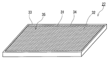
- FIG. 2 is a perspective view schematically illustrating an example of an air filter unit included in the air conditioner of the present invention.
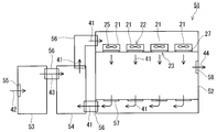
- FIG. 3 is a schematic diagram showing another example of the air conditioner of the present invention.
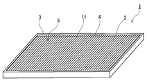
- FIG. 4 is a perspective view schematically showing an example of the air filter unit of the present invention.
- FIG. 5 is a perspective view schematically illustrating an example of a filter pleated pack included in the air filter unit of the present invention.
- FIG. 6 is a diagram for explaining a method of evaluating the amount of deflection of the filter pleat pack provided in the air filter unit by its own weight.
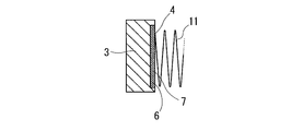
- FIG. 7 is a cross-sectional view schematically showing an example of the air filter unit of the present invention in a state where the peripheral end of the filter pleated pack is supported by a frame.
- FIG. 8 is a cross-sectional view schematically illustrating another example of the air filter unit of the present invention.
- FIG. 9 is a perspective view schematically showing an example of a conventional air filter unit.
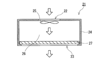
- FIG. 1 shows an FFU 21 as an example of the air conditioner of the present disclosure.
- the FFU 21 has an air flow path 26 having an intake port 22 and an exhaust port 23.
- the intake port 22 is located at one end of the flow path 26.
- the exhaust port 23 is located at the other end of the flow path 26.
- the channel 26 is formed inside the housing 24.
- the FFU 21 includes a blower 25 and an air filter unit 27.
- the blower 25 is a fan.
- the air filter unit 27 is disposed in the flow path 26 and filters the air introduced from the intake port 22.
- the blower 25 is arranged in the flow path 26 and creates a flow of air from the intake port 22 to the exhaust port 23.
- the air introduced into the flow path 26 from the intake port 22 by the operation of the blower 25 is blown out of the FFU 21 from the exhaust port 23 after fine dust is removed when the air passes through the air filter unit 27 (see FIG. 1). See arrow).
- the air filter unit 27 includes a filter pleated pack (hereinafter, referred to as a “pleated pack”) 32 and a frame 33 that supports the pleated pack 32.
- the pleated pack 32 has a structure in which a sheet-shaped filter medium 31 is folded in a pleated shape.
- the frame 33 supports the peripheral end 34 of the pleated pack 32 over the entire circumference.
- the opening area of the air filter unit 27 (the area of the opening 35 of the frame 33) is 1.35 m 2 or more.
- the trapping ability of the air filter unit 27 is equal to or higher than the class H13 (hereinafter, referred to as “class H13”) defined in European Standard (hereinafter, referred to as “EN”) 1822-1: 2009.
- the FFU 21 has a large operating efficiency with respect to the supplied power, while having an air filter unit 27 having a large size and a high trapping ability.
- the power consumption efficiency of the FFU 21 given by the following equation (1) is 600 kWh / (m 2 ⁇ year) or less when the FFU 21 is operated such that the air blowing efficiency ⁇ of the blower becomes 0.75.
- power consumption efficiency kWh / (m 2 ⁇ year) ⁇ (Q ⁇ ⁇ P) / ( ⁇ ⁇ 1000) ⁇ ⁇ (24 ⁇ 365) / S
- Q in equation (1) is the rated flow rate (m 3 / sec) of the air filter unit.
- ⁇ P is the pressure loss (Pa) of the air filter unit with respect to the air passing through the air filter unit at the rated flow rate of the unit.
- S is the opening area (m 2 ) of the air filter unit.
- the blower efficiency ⁇ of the blower is a value that varies depending on the operating conditions of the blower (the operating conditions of the blower filter unit including the blower), and is a value obtained from the power supplied to the blower and the air volume and total pressure generated by the blower. is there.
- the blowing efficiency is calculated by the following equation (2).
- the air volume of the blower in the equation (2) is a value obtained by converting an actually measured value to an air volume in a standard state (temperature: 20 ° C., pressure: 101.3 kPa, relative humidity: 65%, density: 1.20 kg / m 3 ).
- Equation (2): Blow efficiency ⁇ [air volume of blower (m 3 / sec) ⁇ total pressure of blower (kPa)] / shaft power of blower (kW)
- the nominal flow rate (nominal flow rate) Q of the air filter unit is a flow rate determined for each air filter unit by the manufacturer of the air filter unit, and is the maximum flow rate at which the collection performance of the unit is guaranteed by the manufacturer. .
- the pressure loss ⁇ P of the air filter unit can be determined based on a pressure loss test of test method type 1 defined in Japanese Industrial Standards (hereinafter referred to as “JIS”) B9908: 2011.
- JIS Japanese Industrial Standards
- ⁇ P is a value measured at the rated flow rate of the air filter unit to be evaluated.
- the angle of the frame of the air filter unit and the direction of air permeation when evaluating the pressure loss ⁇ P are made to match the angle of the frame and the direction of air permeation during operation of the FFU.
- the pressure loss ⁇ P of the air filter unit, in which the frame is held horizontally during the operation of the FFU and air is transmitted from above to below is such that air is transmitted from above to below the unit while the frame is held horizontally.
- the air filter unit has the same configuration as that of the type 1 test apparatus defined in JIS B9908: 2011, and can fix the air filter unit while holding the frame horizontally.
- a device capable of flowing air from above to below the air filter unit can be used.
- the power consumption efficiency of the FFU 21 is 500 kWh / (m 2 ⁇ year) or less, 400 kWh / (m 2 ⁇ year) or less, 300 kWh / (m 2 ⁇ year) or less, and further 250 kWh / (m 2 ⁇ year) or less. May be.
- the FFU 21 has an air filter unit 27 having an opening area of 1.35 m 2 or more. As the opening area increases, the rated flow rate of the air filter unit 27 can be increased. By increasing the rated flow rate, for example, it is possible to increase the air volume of the FFU 21 including the air filter unit 27, and it is possible to reduce the number of FFUs required for constructing a clean room. The reduction in the number of FFUs contributes to lowering the cost of the clean room and / or improving the maintainability. Also, the rated flow rate of the air filter unit 27 should be larger than the rated flow rate of the air filter module having a structure in which a plurality of air filter units are arranged in a tile shape and having the same opening area (opening area of the main frame). Is possible.
- the air filter module has a frame (sub-frame) for each filter unit arranged in the opening of the main frame, in addition to the frame (main frame) constituting the outer shape of the module.
- the rated flow rate of the air filter module is reduced by at least the area of the sub-frame body in the opening area.
- the opening area of the air filter unit 27 may be 1.38 m 2 or more, 1.44 m 2 or more, or even 1.48 m 2 or more.
- the short side of the opening 35 may be 600 mm or more, 800 mm or more, or even 1000 mm or more.
- the shape of the opening 35 is typically a square.
- the air filter unit 27 having an opening area of 1.35 m 2 typically has a size generally called “4 feet ⁇ 4 feet”.
- the FFU 21 includes an air filter unit 27 having a high trapping ability. Therefore, the FFU 21 can be used for an air conditioner system in a clean room.
- the FFU 21 When used in an air conditioner system for a clean room, the FFU 21 is installed on the ceiling of the clean room, for example, such that the exhaust port 23 faces the room.
- the form and method of installing the FFU 21 in the clean room are not limited to the above example.
- the use of the FFU 21 is not limited to the air conditioner system of a clean room.
- EFU Equipment Fan Filter Unit
- the trapping ability of the air filter unit 27 is class H13 or higher.
- the air filter unit having a trapping ability of class H13 or higher has a high-efficiency particulate air grade (EPA) filter or ULPA (ultra-low penetration) air specified in JIS Z8122: 2000. grade) equivalent to an air filter unit composed of filters.
- the trapping ability of the air filter unit 27 may be equal to or higher than the class U15 defined in EN1822-1: 2009.
- the air filter unit having a trapping ability of class U15 or more corresponds to an air filter unit including the ULPA filter.
- the trapping ability of the air filter unit 27 may be the class H14 or higher, the class U15 or higher, or the class U16 or higher specified in EN1822-1: 2009.
- the air filter unit 27 may be arranged in the flow passage 26 so that the frame 33 is kept horizontal when the FFU 21 is operated. Further, the air filter unit 27 may be disposed so as to be detachable from the flow path 26. However, the arrangement state (for example, position and angle) of the air filter unit 27 in the FFU 21 is not limited as long as it is arranged in the flow path 26.
- the pleat pack 32 may be bent horizontally or downward when the frame 33 is held horizontally with the inflow side of the air (air to be filtered) facing upward.
- the air inflow side is the intake port 22 side when arranged in the FFU 21.
- the FFU 21 can be installed on the ceiling of the creel room so that the frame 33 of the air filter unit 27 is held horizontally.
- the air filter unit 27 includes a mesh (hereinafter, referred to as “lass net” based on a name commonly used by those skilled in the art) connected to the frame 33 to protect the pleat pack 32. You may.
- the air filter unit 27 having a lath net is usually arranged in the FFU 21 such that the lath net is on the exhaust port 23 side with respect to the pleated pack 32.
- a blower 25 is arranged near the air inlet 22 inside the housing 24.
- the arrangement state of the blower 25 in the FFU 21 is not limited as long as the operation of the blower 25 can create a flow of air from the intake port 22 to the exhaust port 23.
- the type of the blower 25 is not limited, and is typically an axial flow type blower.
- an air conditioner system 51 of a clean room 52 is shown in FIG.
- the air conditioner system 51 includes a clean room 52, an external controller 53, and an internal controller 54.
- the external control device 53 and the internal control device 54 and the internal control device 54 and the clean room 52 are connected to each other by a duct 56.
- the air conditioner system 51 includes a plurality of FFUs 21. Each FFU 21 is installed on the ceiling of the clean room 52 so that the frame 33 of the air filter unit 27 is held horizontally.
- An intake port 57 is provided on the floor of the clean room 52.
- the intake port 57 is, for example, a grating floor.
- the entire floor of the clean room 52 may be the air inlet 57.
- the air conditioner system 51 includes an air circulation path from the room of the clean room 52 to the intake port 57, the internal conditioner 54, the intake port 22 of the FFU 21, the air filter unit 27, and the exhaust port 23 of the FFU 21.
- the outside air conditioner 53 includes the outside air inlet 55 and a pre-filter that removes dust contained in the outside air 42 introduced from the outside air inlet 55 to some extent.
- the internal conditioner 54 has a function of mixing the air from the clean room 52 and the outside air 43 from the external conditioner 53 continuously or intermittently according to the operation state of the clean room 52.
- the internal tone adjuster 54 may include a pre-filter and / or an air filter unit that removes dust contained in the air passing through the internal tone adjuster 54. Further, the external adjuster 53 and / or the internal adjuster 54 may have an air temperature adjusting function.
- the operation of the blower 25 of the FFU 21 causes the air from the room of the clean room 52 to sequentially pass through the intake port 57, the internal conditioner 54, the intake port 22 of the FFU 21, the air filter unit 27, and the exhaust port 23 of the FFU 21. Then, the airflow 41 returning to the clean room 52 is generated.
- the airflow 41 that has passed through the internal tone adjuster 54 may include outside air 43.
- the air contained in the airflow 41 is blown into the clean room 52 from the exhaust port 23 after fine dust is removed when passing through the air filter unit 27.
- the air conditioner system 51 shown in FIG. 3 is a down flow type air conditioner system. Note that the clean room 52 is provided with an external exhaust port 58, and a part of the air 44 in the clean room 52 can be discharged to the outside as needed.
- the air conditioner system 51 has a high operation efficiency with respect to the supplied electric power while having the FFU 21 having the air filter unit 27 having a large size and a high trapping ability.
- the arrangement state of the FFU 21 in the air conditioner system 51 is not limited to the example shown in FIG. 3 as long as the airflow 41 is generated by the operation of the blower 25 and the desired performance as the clean room 52 is achieved.
- At least one FFU may be the FFU 21 described above.
- all the FFUs are the FFUs 21 described above.
- the air conditioner system 51 can have any configuration as long as the air conditioner system 51 includes the FFU 21.
- the air conditioner according to the present disclosure may include, for example, the air filter unit 1 according to the present disclosure described below as the air filter unit 27.
- FIG. 4 shows an example of the air filter unit 1.
- the air filter unit 1 shown in FIG. 4 includes a pleated pack 2 and a frame 3 that supports the pleated pack 2.
- the frame 3 supports the peripheral end 4 of the pleat pack 2 over the entire circumference.
- the opening area (the area of the opening 5 of the frame 3) S of the air filter unit 1 is 1.35 m 2 or more.
- the pleated pack 2 has a structure in which a sheet-shaped filter medium 11 is folded in a pleated shape.
- the pleated pack 2 has a bead 12.
- the bead 12 is a string-shaped body made of a resin, and is a kind of a spacer that maintains the pleated shape of the filter medium 11.
- the bead 12 is disposed on the surface of the folded filter medium 11 so as to draw a continuous line or an intermittent line that advances along a direction intersecting the pleated line 13 (fold line) of the filter medium 11.
- the PF value (Performance Factor) of the filter medium 11 constituting the pleated pack 2 is 23 or more.
- the PF value is a value that is an index of the collecting performance of the filter medium.
- the filter medium 11 having a PF value of 23 or more has high collection performance. Therefore, the air filter unit 1 including the pleated pack 2 constituted by the filter medium 11 can have high trapping performance.
- the frame 3 is held horizontally (in other words, the frame 3 is held so that the direction of the air flow passing through the air filter unit 1 is vertical), and the pleats are removed except for the peripheral end 4.
- the pleated pack 2 evaluated as having the pack 2 in a free state has a deflection of its own weight of 30 mm or less.
- the center of the pleat pack excluding the peripheral edge is moved downward by gravity.
- the downward deflection of the center of the pleat pack due to gravity (hereinafter, referred to as “the weight deflection of the pleat pack”) increases. Show the trend.
- the weight deflection of the pleated pack increases the structural pressure loss of the air filter unit, and the increase in the structural pressure loss increases the pressure loss ⁇ P of the air filter unit.
- a pleat pack bent by gravity may come into contact with the lath net.
- the structural pressure loss of the air filter unit also increases with an increase in the amount of contact of the pleat pack with the lath net.
- the opening area S is 1.35 m 2 or more, the frame body is held horizontally, and the weight of the pleated pack evaluated as being free except for the peripheral end portion 4 ( Hereinafter, referred to as “self-weight deflection amount B”) is 30 mm or less.
- self-weight deflection amount B the weight of the pleated pack evaluated as being free except for the peripheral end portion 4
- the increase in the structural pressure loss due to the deflection of the pleat pack 2 under its own weight is suppressed, including the increase in the structural pressure loss due to the increase in the amount of contact with the lath net. Therefore, in the air filter unit 1, an increase in the pressure loss ⁇ P, particularly, the pressure loss ⁇ P when the frame 3 is held horizontally is suppressed. Therefore, in the air conditioner including the air filter unit 1, the power consumption efficiency can be reduced.
- the weight B of the pleated pack 2 may be 27 mm or less, 26 mm or less, 25 mm or less, 24 mm or less, 22 mm or less, 20 mm or less, or even 15 mm or less.
- the lower limit of the self-weight deflection B is, for example, 0 mm or more, and may be 1 mm or more, 3 mm or more, or even 5 mm or more.
- the weight B of the pleat pack can be evaluated, for example, as follows (see FIG. 6). First, as shown in (a), the air filter unit 61 is placed on a test table 63 having an opening 64 so that the frame 62 of the air filter unit 61 to be evaluated is horizontal. The air filter unit 61 is placed so that the test bench 63 does not inhibit the deflection of the pleat pack 65 of the unit 61. The placement in which the self-weight deflection is not hindered can be performed by, for example, adjusting the position of the air filter unit 61 with respect to the opening 64. The opening 64 may have the same shape and size as the opening of the frame 62.
- the air filter unit 61 may be placed so that the opening of the frame 62 and the opening 64 coincide with each other when viewed from a direction perpendicular to the upper surface of the test table 63.
- the pleated pack 65 is bent by its own weight.
- the plate 66 is slowly and vertically raised from below.
- the plate 66 has an area of 95% or more of the area of the opening of the frame body 62 and has a shape capable of passing through the opening 64 in the vertical direction and a positional relationship with the opening 64.
- the plate 66 is raised so that its top surface remains horizontal.
- the height y1 of the plate 66 when the upper surface of the plate 66 contacts one of the pleat lines of the pleat pack 65 is recorded.
- the contact with the pleat line is determined by observing the pleat pack 65 and the plate 66 from the side of the air filter unit 61 in the direction in which the pleat line extends.
- the plate 66 is further raised, and the height of the plate 66 when the upper surface of the plate 66 contacts at least 90% of the pleat lines of all the pleat lines of the pleat pack 65.
- Record y2 The absolute value of the difference between the heights y2 and y1 can be used as the amount of deflection B of the pleat pack 65 under its own weight.
- the self-weight deflection amount B can be based on a horizontal plane assuming that at least 90% of the pleat lines of all the pleat lines of the pleat pack 65 are on one horizontal plane.
- the short side of the opening 5 of the air filter unit 1 may be 600 mm or more, 800 mm or more, or even 1000 mm or more.
- the shape of the opening 5 is typically a square.
- the air filter unit 1 having an opening area of 1.35 m 2 typically has a size generally called “4 feet ⁇ 4 feet”.
- the rated flow rate can be increased as compared with the air filter unit having the smaller opening area.
- the rated flow rate of the air filter unit 1 can be made larger than the rated flow rate of an air filter module having the same opening area (opening area of the main frame).
- the opening area of the air filter unit 1 may be 1.38 m 2 or more, 1.44 m 2 or more, or even 1.48 m 2 or more.
- the PF value of the filter medium 11 constituting the pleated pack 2 is 23 or more.
- a filter medium having a PF value of 23 or more can be used as a filter medium for a high-performance or ultra-high-performance air filter unit used in a clean room such as the semiconductor industry and the pharmaceutical industry.
- the PF value of the filter medium is determined by the pressure drop PL F (unit: mmH 2 O) of the filter medium when air is permeated at a linear velocity of 5.3 cm / sec, and air permeation at a linear velocity of 5.3 cm / sec.
- the PF value of the filter medium 11 may be 25 or more, 26 or more, 27 or more, 28 or more, or even 30 or more.
- the pressure loss PL F of the filter medium 11 is, for example, 10 to 400 Pa, and may be 100 to 400 Pa, or 100 to 350 Pa.
- the pressure loss PL F of the filter medium can be evaluated as follows.
- a measurement holder composed of two plates having the same shape is prepared. Each plate has a through hole (having a circular cross-sectional shape and an effective ventilation area of 100 cm 2 ).
- the filter medium to be evaluated is sandwiched between both plates.
- the filter medium is sandwiched such that the through holes of both plates coincide with each other when viewed from a direction perpendicular to the main surface of the plate, and the filter medium covers the openings of the through holes of each plate. Further, the filter medium is sandwiched so that no gap is formed between each plate and the filter medium.
- a fixing member such as an o-ring or a double-sided adhesive tape may be used to prevent a gap from being generated.
- a holder is set in a chamber to which a flow meter and a pressure gauge (manometer) are connected so that air passes only through the through-hole and the filter medium located in the through-hole.
- a pressure difference is generated between one surface and the other surface of the holder, and air starts flowing through the through-hole and the filter medium.
- the pressure difference (static pressure difference) when the linear velocity of the air passing through the through-hole and the filter medium becomes 5.3 cm / sec as a measurement value of the flow meter is measured by a pressure gauge.
- the pressure difference measured 8 times for one filter media, the average value, and the pressure loss PL F of the filter medium to be evaluated.
- Collection efficiency CE F of filter medium 11 is, for example, 20-100%, from 90% to 100% may be from 99.9 to 100%.
- Collection efficiency CE F of the filter medium can be evaluated in the following manner.
- a measurement holder composed of two plates having the same shape is prepared. Each plate has a through hole (having a circular cross-sectional shape and an effective ventilation area of 100 cm 2 ).
- the filter medium to be evaluated is sandwiched between both plates.
- the filter medium is sandwiched such that the through holes of both plates coincide with each other when viewed from a direction perpendicular to the main surface of the plate, and the filter medium covers the openings of the through holes of each plate. Further, the filter medium is sandwiched so that no gap is formed between each plate and the filter medium.
- a fixing member such as an o-ring or a double-sided adhesive tape may be used to prevent a gap from being generated.
- a holder is set in a chamber to which a flow meter and a pressure gauge (manometer) are connected so that air passes only through the through-hole and the filter medium located in the through-hole.
- a pressure difference is generated between one surface and the other surface of the holder, and air starts flowing through the through-hole and the filter medium.
- the pressure difference is adjusted so that the linear velocity of the air passing through the through-hole and the filter medium is maintained at 5.3 cm / sec as measured by the flow meter.
- the areal density of the filter medium 11 is, for example, not less than 50 g / m 2 and not more than 100 g / m 2 .
- the upper limit of the areal density may be 90 g / m 2 or less, 80 g / m 2 or less, 75 g / m 2 or less, or even 70 g / m 2 or less.
- the lower limit of the areal density may be 55 g / m 2 or more, and further may be 60 g / m 2 or more.
- the surface density of the filter medium 11 can be determined by dividing the weight of the filter medium 11 by the area of the main surface.
- the filter material 11 can be made of the same material as that of a known filter material.
- the filter medium 11 is, for example, a filter medium made of glass fiber or a filter medium including a porous film of polytetrafluoroethylene (hereinafter referred to as “PTFE”).
- PTFE polytetrafluoroethylene
- the filter medium 11 including a PTFE porous membrane is preferable because a high PF value can be achieved and the self-dusting property is low.
- PTFE porous membranes are typically composed of countless PTFE fibrils, which are fine fibrous structures.
- the PTFE porous membrane may have a PTFE node connected to the fibril.
- the PTFE porous membrane is formed, for example, by molding a mixture of unfired PTFE powder and a liquid lubricant into a film by a method such as extrusion and / or rolling, and removing the liquid lubricant from the obtained unfired film. Thereafter, it can be formed by stretching. After formation of the unfired film, firing may be performed at an arbitrary timing to heat the film to a temperature equal to or higher than the melting point of PTFE.
- the liquid lubricant is, for example, a hydrocarbon oil such as naphtha, white oil, or liquid paraffin. However, the liquid lubricant is not limited as long as it can wet the surface of the PTFE powder and can be removed later.
- stretching examples include stretching at 2 to 60 times in the MD direction (longitudinal direction) of the unfired film, stretching at a stretching temperature of 150 to 390 ° C., and stretching at 10 to 60 times in the TD direction (width direction) of the film.
- This is biaxial stretching in which stretching at a stretching temperature of 40 to 150 ° C. is combined.
- the stretching is not limited to this example.
- the thickness of the porous PTFE membrane is, for example, 1 to 100 ⁇ m.
- the average pore diameter of the PTFE porous membrane is, for example, 0.1 to 50 ⁇ m.
- the porosity of the PTFE porous membrane is, for example, 70 to 98%. Due to the small average pore diameter and the high porosity of the PTFE porous membrane, the pressure loss of the filter medium 11 including the PTFE porous membrane can be reduced and the collection efficiency can be increased.
- the porosity of the PTFE porous membrane can be evaluated as follows. The PTFE porous membrane to be evaluated is cut into a certain size (for example, a circle having a diameter of 6 cm), and its volume and weight are obtained. By substituting the obtained volume and weight into the following equation (5), the porosity of the PTFE porous membrane can be calculated.
- V (unit: cm 3 ) is the measured volume
- W (unit: g) is the measured weight
- D (unit: g / cm 3 ) is the true density of PTFE (2.2 g / cm). 3 ).
- Porosity (%) 100 ⁇ [V ⁇ (W / D)] / V
- the areal density of the PTFE porous membrane is, for example, 0.05 to 10 g / m 2 , and may be 0.1 to 5 g / m 2 or 0.3 to 3 g / m 2 .
- the pressure loss and the collection efficiency of the PTFE porous membrane can be evaluated by applying the above-described method of measuring the pressure loss and the collection efficiency of the filter medium.
- the PTFE porous membrane to be evaluated may be fixed to the measurement holder instead of the filter medium.
- the PF value, pressure loss, and collection efficiency of the PTFE porous membrane usually have the same values as the PF value, pressure loss, and collection efficiency of the filter medium 11, respectively.
- the filter medium 11 including the porous PTFE membrane may further include a gas-permeable supporting material.
- the air-permeable supporting material is a layer having higher air permeability in the thickness direction than the PTFE porous membrane, and has a function of protecting the PTFE porous membrane.
- the air-permeable supporting material is composed of, for example, fibers such as short fibers and / or long fibers.
- the breathable support is, for example, a nonwoven fabric, a woven fabric, or a mesh. A breathable support made of a nonwoven fabric is preferable because of its excellent breathability, strength and flexibility.
- Materials constituting the breathable support material include, for example, polyolefins such as polyethylene (PE) and polypropylene (PP); polyesters such as polyethylene terephthalate (PET); polyamides containing aromatic polyamides; and composite materials thereof.
- the material is preferably a polyolefin, and more preferably PE, because of its excellent bonding property with the PTFE porous membrane.
- the composite material constituting the breathable support material is a composite fiber having a core-sheath structure of a core and a sheath covering the core.
- the material constituting each part differs between the core part and the sheath part of the composite fiber. It is preferable that the melting point of the material forming the sheath is lower than the melting point of the material forming the core.
- the material constituting the core is, for example, polyester such as PET.
- the material constituting the sheath is, for example, a polyolefin such as PE. When the material constituting the sheath portion is a polyolefin, the polyolefin having excellent bonding properties with the PTFE porous membrane can be exposed on the bonding surface of the breathable support material with the PTFE porous membrane.
- the average fiber diameter of the fibers constituting the air-permeable supporting material is, for example, 1 to 50 ⁇ m, and may be 1 to 30 ⁇ m, or 10 to 30 ⁇ m.
- the area density of the air-permeable supporting material is, for example, not less than 20 g / m 2 and not more than 70 g / m 2 .
- the upper limit of the areal density may be 50 g / m 2 or less, 40 g / m 2 or less, 35 g / m 2 or less, or even 30 g / m 2 or less.
- the lower limit of the areal density may be 25 g / m 2 or more.
- the porous PTFE membrane and the air-permeable supporting material are usually bonded to each other.
- the joining method is not limited, and is, for example, heat lamination or lamination using an adhesive. Joining by thermal lamination is preferred because it can suppress an increase in pressure loss at the joining portion.
- the filter medium 11 may include two or more porous PTFE membranes and / or two or more air-permeable supporting materials.
- the filter medium 11 has, for example, a three-layer structure including one porous PTFE membrane and two air-permeable supporting members sandwiching the porous membrane.
- the filter medium 11 may have a multilayer structure of three or more layers.
- both outermost layers of the filter medium 11 are gas-permeable supporting materials. In this case, the strength and durability of the filter medium 11 can be improved. Further, in this case, it is possible to suppress a decrease in the collection efficiency when the filter medium 11 is pleated into the pleated pack 2.
- the filter medium 11 may have a configuration other than that exemplified above as long as the amount of deflection B of its own weight of the pleated pack 2 is 30 mm or less.
- the filter medium 11 including the porous PTFE membrane and the air-permeable supporting material can be manufactured by, for example, joining the porous PTFE membrane and the air-permeable supporting material by thermal lamination.
- the pleated height H of the filter medium 11 in the pleated pack 2 (distance between one surface and the other surface of the pleated pack 2; see FIG. 5) is, for example, 25 to 50 mm, 25 to 40 mm, and 25 to 35 mm. There may be.
- the pleated shape of the filter medium in the pleated pack affects the structural pressure loss of the air filter unit. When the pleat height H is in these ranges, the structural pressure loss of the air filter unit 1 can be further reduced.
- the pleated width W of the filter medium 11 in the pleated pack 2 (the interval between adjacent pleated lines 13 on one surface of the pleated pack 2; see FIG. 5) is, for example, 2.5 to 4.2 mm, and 2.8. To 3.6 mm, or 3.0 to 3.4 mm. When the pleat width W is in these ranges, the structural pressure loss of the air filter unit 1 can be further reduced.
- the bead 12 may be arranged on one surface of the filter medium 11 or on both surfaces.
- the beads 12 are preferably arranged on the surface of the gas-permeable supporting material.
- the beads 12 can be formed, for example, by applying a molten resin to the surface of the filter medium 11 in a string shape.
- the resin constituting the bead 12 is, for example, polyamide, polyolefin, or ethylene-vinyl acetate copolymer.
- the resin forming the bead 12 is not limited to the above example.
- the arrangement amount of the beads 12 in the pleated pack 2 (the arrangement amount per 1 m 2 of the opening area of the air filter unit 1, unit: g / m 2 ) is, for example, 40 to 80 g / m 2 , and 40 to 70 g / m 2. , 40 to 60 g / m 2 , or even 40 to 50 g / m 2 .
- the arrangement amount of the bead 12 in the pleated pack 2 is within these ranges, the deflection B of its own weight of the pleated pack 2 can be reduced to 30 mm or less.
- the arrangement amount of the beads 12 on each surface may be substantially the same. In the present specification, when the ratio of the arrangement amount of the beads 12 is in the range of 0.95 to 1.05, it is assumed that they are substantially the same.
- a known method can be applied to the pleating of the filter medium 11.
- the pleating of the filter medium 11 can be performed using, for example, a reciprocating or rotary pleating machine.
- the frame 3 is made of, for example, a metal, a resin, or a composite material thereof.
- the pleat pack 2 can be fixed to the frame 3 simultaneously with the molding of the frame 3.
- the configuration of the frame 3 may be the same as the configuration of the frame provided in the conventional air filter unit.
- FIG. 7 shows an example of a state where the peripheral end 4 is supported by the frame 3.
- the peripheral end 4 is fixed to the frame 3 in the recess 6 of the frame 3 having a C-shaped cross section.
- the caulking agent 7 is filled in the recess 6 over the entire circumference of the frame 3, and the peripheral end 4 is supported by the filled caulking agent 7.
- the caulking agent is, for example, a two-part epoxy caulking agent.
- the caulking agent is not limited to the above example.
- the air filter unit 1 may include further members other than the pleat pack 2 and the frame 3 as long as the amount of self-deflection B of the pleat pack 2 is 30 mm or less.
- FIG. 8 shows an example of the air filter unit 1 including a lath net 8 as a further member.
- the lath net 8 of the air filter unit 1 shown in FIG. 8 is arranged so as to cover the pleated pack 2 when the unit 1 is viewed from the downstream side of the airflow 14 passing through the air filter unit 1 during use.
- the lath net 8 is disposed downstream of the pleat pack 2 in the airflow 14.
- the lath net 8 has a function of protecting the pleated pack 2.
- the lath net 8 is fixed to the frame 3 by inserting the peripheral end of the lath net 8 into the slit 9 formed in the frame 3.
- the method of fixing the lath net 8 to the frame 3 is not limited to this example.
- a lath net provided in a known air filter unit can be used as the net 8.
- the material forming the lath net 8 is, for example, a metal, a resin, or a composite material thereof.
- a typical example of the lath net 8 is a metal mesh such as an expanded metal and a wire mesh.
- the surface of the lath net 8 on the side of the pleated pack 2 be flat in a state of being incorporated in the air filter unit 1. More specifically, the surface preferably does not have a protrusion such as a rib protruding toward the pleated pack 2.
- the air filter unit 1 can have a configuration in which the members connected to the frame 3 are not in contact with the pleated pack 2 when the frame 3 is held vertically. Further, the air filter unit 1 including the lath net 8 can have a configuration in which the lath net 8 or a member connected to the lath net does not contact the pleated pack 2 when the frame 3 is held vertically. .
- the air filter unit 1 may include a pre-filter as a further member other than the pleated pack 2 and the frame 3.
- the pre-filter is typically arranged upstream of the pleat pack 2 so as to cover the pleat pack 2 when the unit 1 is viewed from the upstream side of the air stream 14.
- a pre-filter provided in a known air filter unit can be used.
- the prefilter is made of, for example, a nonwoven fabric.
- the collection efficiency of the pre-filter is usually smaller than the collection efficiency of the filter medium 11.
- the pre-filter can play a role of collecting relatively large particles contained in the air before passing through the pleated pack 2.
- the pressure loss ⁇ P of the air filter unit 1 when the frame body 3 is held horizontally and air is transmitted from above to below the air filter unit 1 at the rated flow rate of the unit 1 is, for example, 110 Pa or less, and 100 Pa or less. Hereinafter, it may be 90 Pa or less, and further may be 60 Pa or less.
- the lower limit of the pressure loss ⁇ P is not limited, but is, for example, 30 Pa or more.
- the pressure loss of the air filter unit can be determined in accordance with the pressure loss test of test method type 1 defined in JIS B 9908: 2011.
- the air filter unit In order to evaluate the pressure loss ⁇ P of the air filter unit in a state in which the frame is held horizontally, for example, the air filter unit has the same configuration as the type 1 test apparatus defined in JIS B9908: 2011, and the frame is held horizontally. In this state, the air filter unit can be fixed while holding the air filter unit, and air can flow from above to below the fixed air filter unit.
- the structural pressure loss of the air filter unit 1 when the frame 3 is held horizontally and air is transmitted from above to below the air filter unit 1 at the rated flow rate of the unit 1 is, for example, 10 Pa or less, and 8 Pa or less. , 6 Pa or less, 5 Pa or less, or even 3 Pa or less.
- the lower limit of the structural pressure loss is not limited, but is, for example, 1 Pa or more.
- the structural pressure loss of the air filter unit 1 can be obtained by subtracting the theoretical pressure loss ⁇ P 0 assuming that there is no structural pressure loss from the pressure loss ⁇ P (actually measured value) of the air filter unit 1.
- the pressure loss of the air filter unit including the filter medium 11 having the specific pressure loss PL F changes in proportion to the linear velocity of the air passing through the filter medium 11 based on the PL F. I do. Therefore, the pressure loss ⁇ P 0 is determined by the pressure loss PL F (unit: Pa) of the filter medium 11 provided in the air filter unit 1, the filtration area FS (unit: m 2 ) of the air filter unit 1, and the rating of the air filter unit 1.
- the flow rate Q unit: m 3 / min
- “5.3” is the linear velocity of the air at the time of measuring the pressure loss PL F of the filter medium 11 (unit: cm / sec).
- “(Q / FS) / 60” is the linear velocity (unit: cm / sec) of the air passing through the filter medium 11 provided in the air filter unit 1 when the air permeates at the rated flow rate Q.
- the filtration area FS of the air filter unit 1 can be calculated from the opening area S and the pleat width W and the pleat height H of the filter medium 11 in the air filter unit 1.
- the ratio of the structural pressure loss to the pressure loss ⁇ P of the air filter unit 1 is, for example, 10% or less, and may be 8% or less, 6% or less, or even 5% or less.
- the lower limit of the ratio is not limited, but is, for example, 2% or more.
- the trapping ability of the air filter unit 1 is, for example, class H13 or higher.
- the trapping ability of the air filter unit 1 may be a class H14 or higher, a class U15 or higher, and a class U16 or higher specified in EN1822-1: 2009.
- the collection efficiency of the air filter unit 1 is, for example, 99.95% or more, 99.99% or more, 99.995% or more, 99.999% or more, 99.9995% or more, and further 99.9999%. It may be the above. Although the upper limit of the collection efficiency is not limited, for example, it is 99.99999% or less.
- the collection efficiency of the air filter unit can be evaluated by the following measurement conditions and measurement methods in accordance with the method specified in EN1822-1: 2009. However, instead of the collection efficiency with respect to the maximum transmission particle size (MPPS), the collection efficiency obtained using test particles of polydispersion (particle size: 0.10 to 0.20 ⁇ m, average particle size: 0.15 ⁇ m) is calculated as follows: The collection efficiency of the air filter unit.
- Test particles PAO (polyalphaolefin)
- Test particle diameter 0.1 ⁇ m or more
- Upstream particle concentration 1.0 ⁇ 10 8 particles / L or more ⁇
- Surface wind speed 0.4 ⁇ 0.1 m / sec According to the method specified in EN1822-1: 2009.
- a probe having a measurement opening of 50 mm ⁇ 10 mm is scanned at a speed of 22 m / sec along the downstream surface of the air filter unit to measure the total number of PAO particles leaking downstream of the opening area of the unit. I do.
- the downstream particle concentration is determined from the total number of the measured PAO particles.
- the air filter unit 1 can be used in a state where the frame 3 is held at an arbitrary angle.
- the air filter unit 1 can be used in a state where the frame 3 is held horizontally.
- the pleat pack 2 may be bent horizontally or downward when the frame 3 is held horizontally with the inflow side of the air (air to be filtered) facing upward.
- the weight deflection B is 30 mm or less.
- the air filter unit 1 can be used by being incorporated in an air conditioner, for example.
- the air conditioner is, for example, the above-described air conditioner of the present disclosure.
- the air conditioner may include the air filter unit 1 as the air filter unit 27.
- the air filter unit 1 may be arranged in an air flow path in an air conditioner with the frame 3 held horizontally.
- the air filter unit 1 may be disposed so as to be detachable from the flow path.
- the air conditioner including the air filter unit 1 is, for example, an FFU (FFU includes EFU) and an air conditioner system including the FFU. More specific examples of the air conditioner including the air filter unit 1 are the FFU 21 shown in FIG. 1 and the air conditioner system shown in FIG.
- the air conditioner is, for example, a clean room air conditioner.
- the power consumption efficiency of the FFU was calculated by the following equation (1) from the rated flow rate Q and the opening area S of the air filter unit, and the pressure loss ⁇ P of the air filter unit obtained by the above evaluation.
- the blowing efficiency ⁇ in the equation (1) was set to 0.75.
- power consumption efficiency kWh / (m 2 ⁇ year) ⁇ (Q ⁇ ⁇ P) / ( ⁇ ⁇ 1000) ⁇ ⁇ (24 ⁇ 365) / S
- PTFE fine powder F-104, manufactured by Daikin Industries
- dodecane as a liquid lubricant
- the preform was paste-extruded into a rod shape, and the obtained formed body was roll-rolled to obtain a 200- ⁇ m-thick strip-shaped sheet.
- the obtained sheet was stretched in the MD direction at a stretching temperature of 250 ° C. and a stretching ratio of 15 times, and then stretched in the TD direction at a stretching temperature of 170 ° C. and a stretching ratio of 30 times.
- the stretched sheet was fired at 500 ° C. to obtain a PTFE porous film A.
- the thickness of the obtained porous PTFE membrane A was 3 ⁇ m.
- a filter medium A having a laminated structure of a gas-permeable support material / a porous PTFE membrane / a gas-permeable support material.
- Elastic S0403WDO made by Unitika was used as the air-permeable supporting material.
- Surface density of the resulting filter medium A is 81 g / m 2
- the collection efficiency CE F 99.90% pressure loss PL F is 101 Pa
- PF value was 30.0.
- a PTFE porous membrane B was obtained in the same manner as the formation of the PTFE porous membrane A, except that the stretching temperature in the TD direction was 110 ° C. The thickness of the obtained porous PTFE membrane B was 4 ⁇ m. Next, a filter medium A was formed except that a porous PTFE membrane B was used in place of the porous PTFE membrane A, and Elastic S0303WDO (unit thickness: 230 ⁇ m, area density: 30 g / m 2 ) made by Unitika was used as a gas-permeable supporting material.
- a filter medium B having a laminated structure of a gas-permeable support material / a porous PTFE membrane / a gas-permeable support material was obtained.
- Surface density of the resulting filter medium B is 61 g / m 2
- the collection efficiency CE F is 99.991%
- the pressure loss PL F is 138Pa
- PF value was 28.7.
- a porous PTFE membrane C was obtained in the same manner as the formation of the porous PTFE membrane A, except that the stretching ratio in the MD direction was 10 times and the stretching temperature in the TD direction was 110 ° C. The thickness of the obtained porous PTFE membrane C was 5 ⁇ m.
- a filter medium C having a laminated structure of a gas-permeable support material / a porous PTFE membrane / a gas-permeable support material was obtained.
- Surface density of the resulting filter medium C is 61 g / m 2
- the collection efficiency CE F is 99.9999%
- the pressure loss PL F is 221Pa
- PF value was 26.6.
- a porous PTFE membrane D was obtained in the same manner as the formation of the porous PTFE membrane A, except that the stretching ratio in the MD direction was 9 times and the stretching temperature in the TD direction was 110 ° C. The thickness of the obtained porous PTFE membrane D was 5 ⁇ m.
- a filter medium A was formed except that the porous PTFE membrane D was used in place of the porous PTFE membrane A, and that Unitesika Elves S0303WDO (thickness 230 ⁇ m, area density 30 g / m 2 ) was used as the air-permeable support material.
- a filter medium D having a laminated structure of a gas-permeable support material / a porous PTFE membrane / a gas-permeable support material was obtained.
- Surface density of the resulting filter medium D is 61 g / m 2
- the collection efficiency CE F is 99.99998%
- pressure loss PL F is 250 Pa
- PF value was 26.3.
- a glass medium SB320-A (having a thickness of 380 ⁇ m) manufactured by Hokuetsu Paper Mill was prepared.
- the surface density of the filter medium E is 70 g / m 2
- the collection efficiency CE F is 99.97%
- the pressure loss PL F is 278Pa
- PF value was 12.4.
- a filter medium F As a filter medium F, a glass medium SB380-A (380 ⁇ m thick) made by Hokuetsu Paper Mill was prepared. The surface density of the filter medium F is 70 g / m 2, the collection efficiency CE F is 99.992%, the pressure loss PL F is 315Pa, PF value was 12.7.
- Filter media G Hokuetsu Paper Glass Filter Medium SB111-A (thickness: 380 ⁇ m) was prepared.
- the surface density of the filter medium G is 73 g / m 2
- the collection efficiency CE F is 99.999%
- the pressure loss PL F is 380Pa
- PF value was 12.9.
- Example 1 The filter medium A was pleated with a pleated height H of 30 mm and a pleated width W of 3.2 mm. Next, a hot-melt adhesive (technomelt Q3115, manufactured by Henkel) containing an ethylene-vinyl acetate copolymer was applied to one surface of the pleated filter medium A to form a bead, thereby producing a pleated pack. . The arrangement amount of the beads was 62 g / m 2 .
- the formed pleated pack is placed on an aluminum frame (opening area: 1.35 m 2 , thickness: 75 mm) having an outer dimension of 1220 mm ⁇ 1220 mm and an opening dimension of 1180 mm ⁇ 1180 mm.
- An air filter unit was obtained by fixing with a caulking agent so as to be in close contact with the body.
- a caulking agent a two-component epoxy caulking agent (a mixture of Macroplast 8104MC-18 and Macroplast UK5400 manufactured by Henkel at a ratio of 3: 1 (weight ratio)) was used.
- the rated flow rate Q of the obtained air filter unit is 40 m 3 / min, the collection efficiency is 99.980%, the pressure loss ⁇ P is 49.7 Pa, the structural pressure loss is 2.5 Pa, and the ratio of the structural pressure loss to the pressure loss ⁇ P is:
- the weight B was 27 mm, the weight deflection B was 27 mm, and the class of the trapping ability defined in EN1822-1: 2009 was equivalent to Class H13.
- Example 2 An air filter unit was obtained in the same manner as in Sample 1, except that the filter medium B was used in place of the filter medium A, and the pleat height H in the pleating was 35 mm.
- the rated flow rate Q of the obtained air filter unit is 40 m 3 / min, the collection efficiency is 99.997%, the pressure loss ⁇ P is 59.9 Pa, the structural pressure loss is 4.7 Pa, and the ratio of the structural pressure loss to the pressure loss ⁇ P is: 7.8%, its own weight deflection B was 26 mm, and the category of the trapping ability specified in EN1822-1: 2009 was equivalent to class H14.
- Example 3 An air filter unit was obtained in the same manner as in Sample 2, except that the arrangement amount of the beads was changed to 48 g / m 2 .
- the rated flow rate Q of the obtained air filter unit is 40 m 3 / min, the collection efficiency is 99.997%, the pressure loss ⁇ P is 59.5 Pa, the structural pressure loss is 4.2 Pa, and the ratio of the structural pressure loss to the pressure loss ⁇ P is:
- the weight B was 7.0 mm
- the weight deflection B was 24 mm
- the class of the trapping ability specified in EN1822-1: 2009 was equivalent to class H14.
- Example 4 An air filter unit was obtained in the same manner as in Sample 2, except that the pleat height H in pleating was set to 40 mm.
- the rated flow rate Q of the obtained air filter unit is 40 m 3 / min, the collection efficiency is 99.998%, the pressure loss ⁇ P is 53.7 Pa, the structural pressure loss is 5.3 Pa, and the ratio of the structural pressure loss to the pressure loss ⁇ P is: 9.9%, the deflection B of its own weight was 24 mm, and the classification of the trapping ability specified in EN1822-1: 2009 was equivalent to class H14.
- Example 5 An air filter unit was obtained in the same manner as in Sample 1, except that the filter medium C was used in place of the filter medium A and the pleat height H in the pleating process was 35 mm.
- the rated flow rate Q of the obtained air filter unit is 40 m 3 / min, the collection efficiency is 99.99993%, the pressure loss ⁇ P is 96.0 Pa, the structural pressure loss is 7.4 Pa, and the ratio of the structural pressure loss to the pressure loss ⁇ P is: 7.8%, its own weight deflection B was 26 mm, and the category of the trapping ability defined in EN1822-1: 2009 was equivalent to class U15.
- Example 6 An air filter unit was obtained in the same manner as in Sample 5, except that the pleat height H in pleating was set to 30 mm.
- the rated flow rate Q of the obtained air filter unit is 40 m 3 / min, the collection efficiency is 99.99990%, the pressure loss ⁇ P is 108.8 Pa, the structural pressure loss is 5.5 Pa, and the ratio of the structural pressure loss to the pressure loss ⁇ P is:
- the self-weight deflection B was 26 mm, and the category of the trapping ability specified in EN1822-1: 2009 was equivalent to class U15.
- Example 7 Comparative example
- An air filter unit was obtained in the same manner as in Sample 1, except that the filter medium D was used in place of the filter medium A, the pleat height H in the pleating process was 35 mm, and the bead arrangement amount was 91 g / m 2.
- the rated flow rate Q of the obtained air filter unit is 40 m 3 / min, the collection efficiency is 99.999999%, the pressure loss ⁇ P is 110.3 Pa, the structural pressure loss is 11.3 Pa, and the ratio of the structural pressure loss to the pressure loss ⁇ P is: 10.2%, the deflection B of its own weight was 33 mm, and the classification of the collecting ability specified in EN1822-1: 2009 was equivalent to class U15.
- Example 8 Comparative example
- An air filter unit was obtained in the same manner as in Sample 1, except that the filter medium E was used in place of the filter medium A, and the pleat height H in the pleating process was set to 40 mm.
- the rated flow rate Q of the obtained air filter unit is 40 m 3 / min, the collection efficiency is 99.990%, the pressure loss ⁇ P is 111.5 Pa, the structural pressure loss is 14.0 Pa, and the ratio of the structural pressure loss to the pressure loss ⁇ P is: 12.6%, the deflection B of its own weight was 28 mm, and the classification of the trapping ability specified in EN1822-1: 2009 was equivalent to class H13.
- Example 9 Comparative example
- An air filter unit was obtained in the same manner as in Sample 1, except that the filter medium F was used instead of the filter medium A, and the pleat height H in the pleating process was set to 40 mm.
- the rated flow rate Q of the obtained air filter unit is 40 m 3 / min, the collection efficiency is 99.9980%, the pressure loss ⁇ P is 126.3 Pa, the structural pressure loss is 15.9 Pa, and the ratio of the structural pressure loss to the pressure loss ⁇ P is: 12.6%, the deflection B of its own weight was 28 mm, and the classification of the collecting ability specified in EN1822-1: 2009 was equivalent to class H14.
- Example 10 Comparative example
- An air filter unit was obtained in the same manner as in Sample 1, except that the filter medium G was used in place of the filter medium A and the pleat height H in the pleating process was set to 40 mm.
- the rated flow rate Q of the obtained air filter unit is 40 m 3 / min, the collection efficiency is 99.9998%, the pressure loss ⁇ P is 153.3 Pa, the structural pressure loss is 20.1 Pa, and the ratio of the structural pressure loss to the pressure loss ⁇ P is: 13.1%, the self-weight deflection B was 29 mm, and the category of the trapping ability specified in EN1822-1: 2009 was equivalent to class U15.
- the air conditioner of the present invention can be used, for example, as a clean room air conditioner that supplies clean air to a clean room.
Abstract
A fan filter unit is provided in which, when operating such that the blowing efficiency η of a blower is 0.75, the power consumption efficiency, given by the formula below, is less than or equal to 600 kWh/(m2*year). Q in the equation below is the rated flow rate (m3/s) of the air filter unit, ΔP is the pressure loss (Pa) of the air filter unit for air passing through the air filter unit at the rated flow rate of said unit, and S is the open area (m2) of the air filter unit. Formula: Power consumption efficiency kWh/(m2*yr) = {(Q×ΔP)/(η×1000)}×(24×365)/S.This air conditioner is suitable to reducing power consumption even when the air filter unit is large in size and has a high collection capacity.
Description
本発明は、エアフィルタユニットと、エアフィルタユニットを備える空調機とに関する。
The present invention relates to an air filter unit and an air conditioner including the air filter unit.
クリーンルーム等の空間に清浄空気を供給する大型の空調機は、一般に、空気を濾過処理する複数のエアフィルタユニットを備える。エアフィルタユニットは、空調機における空気の流路に配置される。空気に含まれる微細な塵芥は、エアフィルタユニットを空気が透過する際に除去される。エアフィルタユニットの典型的な一例を、図9に示す。図9に示すエアフィルタユニット101は、フィルタプリーツパック102と、フィルタプリーツパック102の周端部を全周にわたって支持する枠体103とを備える。フィルタプリーツパック102は、シート状のフィルタ濾材104がプリーツ加工により折り畳まれた構造を有する。エアフィルタユニット101では、フィルタ濾材104の折り畳み構造によって、通気面積に比べて大きな濾過面積を確保できる。通気面積は、通常、エアフィルタユニット101の開口面積である。また、フィルタプリーツパック102の周端部を全周にわたって支持する枠体103によって、エアフィルタユニット101としての取扱性が向上し、空調機におけるエアフィルタユニット101の配置及び交換が容易となる。エアフィルタユニット101は、例えば、枠体103を水平に保持した状態で空調機に固定される。
A large air conditioner that supplies clean air to a space such as a clean room generally includes a plurality of air filter units for filtering air. The air filter unit is arranged in an air flow path in the air conditioner. Fine dust contained in the air is removed when the air passes through the air filter unit. FIG. 9 shows a typical example of the air filter unit. The air filter unit 101 shown in FIG. 9 includes a filter pleated pack 102 and a frame 103 that supports the peripheral end of the filter pleated pack 102 over the entire circumference. The filter pleating pack 102 has a structure in which a sheet-like filter medium 104 is folded by pleating. In the air filter unit 101, a large filtering area can be secured as compared with the ventilation area due to the folded structure of the filter medium 104. The ventilation area is usually the opening area of the air filter unit 101. In addition, the frame 103 that supports the peripheral end of the filter pleated pack 102 over the entire circumference improves the handleability of the air filter unit 101, and facilitates the arrangement and replacement of the air filter unit 101 in the air conditioner. The air filter unit 101 is fixed to an air conditioner, for example, with the frame 103 held horizontally.
特許文献1には、エアフィルタユニットが固定された送風機フィルタユニット(ファンフィルタユニット(FFU))を天井に備えるクリーンルームが開示されている。FFUは、エアフィルタユニットの枠体を水平に保持した状態で天井に設置されている。また、特許文献1には、クリーンルームが備える複数のFFU間で運転強度(風量)を相違させる制御によってクリーンルームの消費電力を削減する技術が開示されている。
Patent Document 1 discloses a clean room in which a blower filter unit (fan filter unit (FFU)) to which an air filter unit is fixed is provided on a ceiling. The FFU is installed on the ceiling with the frame of the air filter unit held horizontally. Further, Patent Literature 1 discloses a technique for reducing power consumption of a clean room by controlling the operation intensity (air volume) between a plurality of FFUs included in the clean room.
しかし、複数のFFU間の風量制御は煩雑であり、空調機及びその使用環境によっては十分に消費電力を削減できないこともある。本発明者らの検討によると、個々のエアフィルタユニットのサイズが大きく、捕集効率が高い場合には、消費電力の削減は特に困難である。
However, the air volume control between a plurality of FFUs is complicated, and the power consumption may not be sufficiently reduced depending on the air conditioner and its use environment. According to the study by the present inventors, it is particularly difficult to reduce power consumption when the size of each air filter unit is large and the collection efficiency is high.
本発明は、個々のエアフィルタユニットのサイズが大きく、捕集能力が高い場合であっても、消費電力を削減することに適した空調機と、この空調機に適したエアフィルタユニットとを提供することを目的とする。
The present invention provides an air conditioner suitable for reducing power consumption even when the size of each air filter unit is large and the trapping capacity is high, and an air filter unit suitable for this air conditioner. The purpose is to do.
本発明は、
吸気口及び排気口を有する空気の流路と、
前記吸気口から前記排気口への前記空気の流れを作り出す送風機と、
前記流路に配置され、前記吸気口から導入された前記空気を濾過処理するエアフィルタユニットと、を有する送風機フィルタユニットを備え、
前記エアフィルタユニットは、フィルタプリーツパックと、前記フィルタプリーツパックの周端部を全周にわたって支持する枠体と、を備え、
前記エアフィルタユニットの開口面積が1.35m2以上であり、
前記エアフィルタユニットの捕集能力が、欧州規格(EN)1822-1:2009に定められたクラスH13以上であり、
前記送風機の送風効率ηが0.75となるように前記送風機フィルタユニットを運転したときに、以下の式により与えられる前記送風機フィルタユニットの消費電力効率が600kWh/(m2・年)以下である空調機、
を提供する。
式:消費電力効率kWh/(m2・年)={(Q×ΔP)/(η×1000)}×(24×365)/S
前記式のQは、前記エアフィルタユニットの定格流量(m3/秒)であり、ΔPは、前記エアフィルタユニットを当該ユニットの定格流量で透過する空気に対する前記エアフィルタユニットの圧力損失(Pa)であり、Sは、前記エアフィルタユニットの開口面積(m2)である。 The present invention
An air flow path having an intake port and an exhaust port,
A blower that creates the flow of the air from the intake port to the exhaust port;
An air filter unit disposed in the flow path and filtering the air introduced from the intake port, comprising a blower filter unit,
The air filter unit includes: a filter pleated pack; and a frame body that supports a peripheral end of the filter pleated pack over the entire circumference.
An opening area of the air filter unit is 1.35 m 2 or more;
The air filter unit has a trapping ability of class H13 or more defined in European Standard (EN) 1822-1: 2009,
When the blower filter unit is operated such that the blower efficiency η of the blower becomes 0.75, the power consumption efficiency of the blower filter unit given by the following equation is 600 kWh / (m 2 · year) or less. air conditioner,
I will provide a.
Formula: power consumption efficiency kWh / (m 2 · year) = {(Q × ΔP) / (η × 1000)} × (24 × 365) / S
Q in the above equation is a rated flow rate of the air filter unit (m 3 / sec), and ΔP is a pressure loss (Pa) of the air filter unit with respect to air passing through the air filter unit at the rated flow rate of the unit. And S is the opening area (m 2 ) of the air filter unit.
別の側面から、本発明は、上記空調機に適したエアフィルタユニットを提供する。
即ち、本発明は、
フィルタプリーツパックと、前記フィルタプリーツパックの周端部を全周にわたって支持する枠体と、を備え、
開口面積が1.35m2以上であり、
前記フィルタプリーツパックを構成するフィルタ濾材のPF値が23以上であり、
前記枠体を水平に保持し、前記周端部を除いて前記フィルタプリーツパックを自由な状態として評価した前記フィルタプリーツパックの自重たわみ量が30mm以下であるエアフィルタユニット、
を提供する。 From another aspect, the present invention provides an air filter unit suitable for the air conditioner.
That is, the present invention
A filter pleating pack, and a frame that supports a peripheral end of the filter pleating pack over the entire circumference,
The opening area is 1.35 m 2 or more,
The PF value of the filter medium constituting the filter pleated pack is 23 or more,
An air filter unit in which the weight of the filter pleat pack is 30 mm or less, which holds the frame body horizontally and evaluates the filter pleat pack as a free state except for the peripheral end portion,
I will provide a.
本発明の空調機は、サイズが大きく、捕集能力が高いエアフィルタユニットを備えながらも、供給される電力に対する高い運転効率を有している。
The air conditioner of the present invention has a large size and an air filter unit having a high trapping capacity, but also has a high operation efficiency with respect to the supplied electric power.
以下、本発明の実施形態について、図面を参照しながら説明する。本発明は、以下の実施形態に限定されない。
Hereinafter, embodiments of the present invention will be described with reference to the drawings. The present invention is not limited to the following embodiments.
[空調機]
本開示の空調機の一例としてFFU21を図1に示す。FFU21は、吸気口22及び排気口23を有する空気の流路26を有する。吸気口22は、流路26の一方の端部に位置する。排気口23は、流路26の他方の端部に位置する。流路26は、筐体24の内部に形成されている。FFU21は、送風機25及びエアフィルタユニット27を有する。送風機25は、ファンである。エアフィルタユニット27は、流路26に配置され、吸気口22から導入された空気を濾過処理する。送風機25は、流路26に配置され、吸気口22から排気口23への空気の流れを作り出す。送風機25の作動によって吸気口22から流路26に導入された空気は、エアフィルタユニット27の透過時に微細な粉塵が除去された後、排気口23からFFU21の外部に吹き出される(図1の矢印を参照)。 [air conditioner]
FIG. 1 shows an FFU 21 as an example of the air conditioner of the present disclosure. The FFU 21 has anair flow path 26 having an intake port 22 and an exhaust port 23. The intake port 22 is located at one end of the flow path 26. The exhaust port 23 is located at the other end of the flow path 26. The channel 26 is formed inside the housing 24. The FFU 21 includes a blower 25 and an air filter unit 27. The blower 25 is a fan. The air filter unit 27 is disposed in the flow path 26 and filters the air introduced from the intake port 22. The blower 25 is arranged in the flow path 26 and creates a flow of air from the intake port 22 to the exhaust port 23. The air introduced into the flow path 26 from the intake port 22 by the operation of the blower 25 is blown out of the FFU 21 from the exhaust port 23 after fine dust is removed when the air passes through the air filter unit 27 (see FIG. 1). See arrow).
本開示の空調機の一例としてFFU21を図1に示す。FFU21は、吸気口22及び排気口23を有する空気の流路26を有する。吸気口22は、流路26の一方の端部に位置する。排気口23は、流路26の他方の端部に位置する。流路26は、筐体24の内部に形成されている。FFU21は、送風機25及びエアフィルタユニット27を有する。送風機25は、ファンである。エアフィルタユニット27は、流路26に配置され、吸気口22から導入された空気を濾過処理する。送風機25は、流路26に配置され、吸気口22から排気口23への空気の流れを作り出す。送風機25の作動によって吸気口22から流路26に導入された空気は、エアフィルタユニット27の透過時に微細な粉塵が除去された後、排気口23からFFU21の外部に吹き出される(図1の矢印を参照)。 [air conditioner]
FIG. 1 shows an FFU 21 as an example of the air conditioner of the present disclosure. The FFU 21 has an
図2に示すように、エアフィルタユニット27は、フィルタプリーツパック(以下、「プリーツパック」と記載する)32と、プリーツパック32を支持する枠体33とを備える。プリーツパック32は、シート状のフィルタ濾材31がプリーツ形状に折り畳まれた構造を有する。枠体33は、プリーツパック32の周端部34を全周にわたって支持している。エアフィルタユニット27の開口面積(枠体33の開口35の面積)は1.35m2以上である。エアフィルタユニット27の捕集能力は、欧州規格(以下、「EN」と記載する)1822-1:2009に定められたクラスH13(以下、「クラスH13」と記載する)以上である。
As shown in FIG. 2, the air filter unit 27 includes a filter pleated pack (hereinafter, referred to as a “pleated pack”) 32 and a frame 33 that supports the pleated pack 32. The pleated pack 32 has a structure in which a sheet-shaped filter medium 31 is folded in a pleated shape. The frame 33 supports the peripheral end 34 of the pleated pack 32 over the entire circumference. The opening area of the air filter unit 27 (the area of the opening 35 of the frame 33) is 1.35 m 2 or more. The trapping ability of the air filter unit 27 is equal to or higher than the class H13 (hereinafter, referred to as “class H13”) defined in European Standard (hereinafter, referred to as “EN”) 1822-1: 2009.
FFU21は、サイズが大きく、捕集能力の高いエアフィルタユニット27を有しながらも、供給される電力に対する高い運転効率を有している。以下の式(1)により与えられるFFU21の消費電力効率は、送風機の送風効率ηが0.75となるようにFFU21を運転したときに、600kWh/(m2・年)以下である。
式(1):消費電力効率kWh/(m2・年)={(Q×ΔP)/(η×1000)}×(24×365)/S
式(1)のQは、エアフィルタユニットの定格流量(m3/秒)である。ΔPは、エアフィルタユニットを当該ユニットの定格流量で透過する空気に対するエアフィルタユニットの圧力損失(Pa)である。Sは、エアフィルタユニットの開口面積(m2)である。 TheFFU 21 has a large operating efficiency with respect to the supplied power, while having an air filter unit 27 having a large size and a high trapping ability. The power consumption efficiency of the FFU 21 given by the following equation (1) is 600 kWh / (m 2 · year) or less when the FFU 21 is operated such that the air blowing efficiency η of the blower becomes 0.75.
Formula (1): power consumption efficiency kWh / (m 2 · year) = {(Q × ΔP) / (η × 1000)} × (24 × 365) / S
Q in equation (1) is the rated flow rate (m 3 / sec) of the air filter unit. ΔP is the pressure loss (Pa) of the air filter unit with respect to the air passing through the air filter unit at the rated flow rate of the unit. S is the opening area (m 2 ) of the air filter unit.
式(1):消費電力効率kWh/(m2・年)={(Q×ΔP)/(η×1000)}×(24×365)/S
式(1)のQは、エアフィルタユニットの定格流量(m3/秒)である。ΔPは、エアフィルタユニットを当該ユニットの定格流量で透過する空気に対するエアフィルタユニットの圧力損失(Pa)である。Sは、エアフィルタユニットの開口面積(m2)である。 The
Formula (1): power consumption efficiency kWh / (m 2 · year) = {(Q × ΔP) / (η × 1000)} × (24 × 365) / S
Q in equation (1) is the rated flow rate (m 3 / sec) of the air filter unit. ΔP is the pressure loss (Pa) of the air filter unit with respect to the air passing through the air filter unit at the rated flow rate of the unit. S is the opening area (m 2 ) of the air filter unit.
送風機の送風効率ηは、送風機の運転条件(送風機を備える送風機フィルタユニットの運転条件)によって変化する値であり、送風機に供給される電力と、送風機が生み出す風量及び全圧とから求められる値である。具体的には、送風効率は、以下の式(2)により算出される。ただし、式(2)における送風機の風量は、実測値を、標準状態(温度20℃、圧力101.3kPa、相対湿度65%、密度1.20kg/m3)での風量に換算した値である。
式(2):送風効率η=[送風機の風量(m3/秒)×送風機全圧(kPa)]/送風機の軸動力(kW) The blower efficiency η of the blower is a value that varies depending on the operating conditions of the blower (the operating conditions of the blower filter unit including the blower), and is a value obtained from the power supplied to the blower and the air volume and total pressure generated by the blower. is there. Specifically, the blowing efficiency is calculated by the following equation (2). However, the air volume of the blower in the equation (2) is a value obtained by converting an actually measured value to an air volume in a standard state (temperature: 20 ° C., pressure: 101.3 kPa, relative humidity: 65%, density: 1.20 kg / m 3 ). .
Equation (2): Blow efficiency η = [air volume of blower (m 3 / sec) × total pressure of blower (kPa)] / shaft power of blower (kW)
エアフィルタユニットの定格流量(nominal flow rate)Qは、エアフィルタユニットの製造者によってエアフィルタユニットごとに定められる流量であり、製造者によって当該ユニットの捕集能力が保証される最大の流量である。
The nominal flow rate (nominal flow rate) Q of the air filter unit is a flow rate determined for each air filter unit by the manufacturer of the air filter unit, and is the maximum flow rate at which the collection performance of the unit is guaranteed by the manufacturer. .
エアフィルタユニットの圧力損失ΔPは、日本工業規格(以下、「JIS」と記載する)B9908:2011に定められた試験方法形式1の圧力損失試験に準拠して求めることができる。ただし、ΔPは、評価対象であるエアフィルタユニットの定格流量において測定した値とする。また、圧力損失ΔPを評価する際のエアフィルタユニットの枠体の角度及び空気の透過方向は、FFUの運転時における枠体の角度及び空気の透過方向に一致させる。例えば、FFUの運転時に枠体が水平に保持され、上方から下方へ空気が透過するエアフィルタユニットの圧力損失ΔPは、枠体を水平に保持した状態で当該ユニットの上方から下方へ空気を透過させて評価する。この評価のために、例えば、JIS B9908:2011に定められた形式1の試験装置と同様の構成を有すると共に、枠体を水平に保持した状態でエアフィルタユニットを固定可能であり、かつ、固定したエアフィルタユニットの上方から下方へ空気を流すことが可能な装置を使用できる。
圧 力 The pressure loss ΔP of the air filter unit can be determined based on a pressure loss test of test method type 1 defined in Japanese Industrial Standards (hereinafter referred to as “JIS”) B9908: 2011. Here, ΔP is a value measured at the rated flow rate of the air filter unit to be evaluated. Further, the angle of the frame of the air filter unit and the direction of air permeation when evaluating the pressure loss ΔP are made to match the angle of the frame and the direction of air permeation during operation of the FFU. For example, the pressure loss ΔP of the air filter unit, in which the frame is held horizontally during the operation of the FFU and air is transmitted from above to below, is such that air is transmitted from above to below the unit while the frame is held horizontally. Let me evaluate. For this evaluation, for example, the air filter unit has the same configuration as that of the type 1 test apparatus defined in JIS B9908: 2011, and can fix the air filter unit while holding the frame horizontally. A device capable of flowing air from above to below the air filter unit can be used.
FFU21の消費電力効率は、500kWh/(m2・年)以下、400kWh/(m2・年)以下、300kWh/(m2・年)以下、さらには250kWh/(m2・年)以下であってもよい。
The power consumption efficiency of the FFU 21 is 500 kWh / (m 2 · year) or less, 400 kWh / (m 2 · year) or less, 300 kWh / (m 2 · year) or less, and further 250 kWh / (m 2 · year) or less. May be.
FFU21は、1.35m2以上の開口面積を有するエアフィルタユニット27を有する。開口面積が大きくなると、エアフィルタユニット27の定格流量を増大できる。定格流量の増大により、例えば、エアフィルタユニット27を備えるFFU21の大風量化が可能となり、クリーンルームの構築に要するFFUの数を低減できる。FFUの数の低減は、クリーンルームの低コスト化及び/又はメンテナンス性の向上に寄与する。また、エアフィルタユニット27の定格流量は、複数のエアフィルタユニットがタイル状に配列した構造を有する、開口面積(主枠体の開口面積)が同じエアフィルタモジュールの定格流量に比べて大きくすることが可能である。エアフィルタモジュールは、モジュールの外形を構成する枠体(主枠体)以外にも、主枠体の開口内に配列した各フィルタユニットごとに枠体(副枠体)を有している。エアフィルタモジュールの定格流量は、少なくとも開口面積に占める副枠体の面積分、小さくなる。
The FFU 21 has an air filter unit 27 having an opening area of 1.35 m 2 or more. As the opening area increases, the rated flow rate of the air filter unit 27 can be increased. By increasing the rated flow rate, for example, it is possible to increase the air volume of the FFU 21 including the air filter unit 27, and it is possible to reduce the number of FFUs required for constructing a clean room. The reduction in the number of FFUs contributes to lowering the cost of the clean room and / or improving the maintainability. Also, the rated flow rate of the air filter unit 27 should be larger than the rated flow rate of the air filter module having a structure in which a plurality of air filter units are arranged in a tile shape and having the same opening area (opening area of the main frame). Is possible. The air filter module has a frame (sub-frame) for each filter unit arranged in the opening of the main frame, in addition to the frame (main frame) constituting the outer shape of the module. The rated flow rate of the air filter module is reduced by at least the area of the sub-frame body in the opening area.
エアフィルタユニット27の開口面積は、1.38m2以上、1.44m2以上、さらには1.48m2以上であってもよい。
The opening area of the air filter unit 27 may be 1.38 m 2 or more, 1.44 m 2 or more, or even 1.48 m 2 or more.
開口35の短辺は、600mm以上であってもよく、800mm以上、さらには1000mm以上であってもよい。
短 The short side of the opening 35 may be 600 mm or more, 800 mm or more, or even 1000 mm or more.
開口35の形状は、典型的には、正方形である。開口35の形状が正方形である場合、1.35m2の開口面積を有するエアフィルタユニット27は、典型的には、「4フィート×4フィート」と一般に称されるサイズを有している。
The shape of the opening 35 is typically a square. When the shape of the opening 35 is a square, the air filter unit 27 having an opening area of 1.35 m 2 typically has a size generally called “4 feet × 4 feet”.
FFU21は、高い捕集能力を有するエアフィルタユニット27を備える。このため、FFU21は、クリーンルームの空調機システムに使用できる。クリーンルームの空調機システムに使用する場合、FFU21は、例えば、排気口23が室内に面するようにクリーンルームの天井に設置される。ただし、クリーンルームへのFFU21の設置の形態及び方法は、上記例に限定されない。また、FFU21の用途は、クリーンルームの空調機システムに限定されない。例えば、排気口23周辺の比較的限られた範囲に清浄空気を供給するEFU(Equipment Fan Filter Unit)としてFFU21を使用することも可能である。
The FFU 21 includes an air filter unit 27 having a high trapping ability. Therefore, the FFU 21 can be used for an air conditioner system in a clean room. When used in an air conditioner system for a clean room, the FFU 21 is installed on the ceiling of the clean room, for example, such that the exhaust port 23 faces the room. However, the form and method of installing the FFU 21 in the clean room are not limited to the above example. Further, the use of the FFU 21 is not limited to the air conditioner system of a clean room. For example, it is possible to use the FFU 21 as an EFU (Equipment Fan Filter Unit) that supplies clean air to a relatively limited area around the exhaust port 23.
エアフィルタユニット27の捕集能力は、クラスH13以上である。クラスH13以上の捕集能力を有するエアフィルタユニットは、初期圧力損失が245Pa以下である場合、JIS Z8122:2000に定められたHEPA(high-efficiency particulate air grade)フィルタ又はULPA(ultra-low penetration air grade)フィルタから構成されるエアフィルタユニットに相当する。エアフィルタユニット27の捕集能力は、EN1822-1:2009に定められたクラスU15以上であってもよい。クラスU15以上の捕集能力を有するエアフィルタユニットは、初期圧力損失が245Pa以下である場合、上記ULPAフィルタから構成されるエアフィルタユニットに相当する。エアフィルタユニット27の捕集能力は、EN1822-1:2009に定められたクラスH14以上、クラスU15以上、さらにはクラスU16以上であってもよい。
捕 The trapping ability of the air filter unit 27 is class H13 or higher. When the initial pressure loss is 245 Pa or less, the air filter unit having a trapping ability of class H13 or higher has a high-efficiency particulate air grade (EPA) filter or ULPA (ultra-low penetration) air specified in JIS Z8122: 2000. grade) equivalent to an air filter unit composed of filters. The trapping ability of the air filter unit 27 may be equal to or higher than the class U15 defined in EN1822-1: 2009. When the initial pressure loss is 245 Pa or less, the air filter unit having a trapping ability of class U15 or more corresponds to an air filter unit including the ULPA filter. The trapping ability of the air filter unit 27 may be the class H14 or higher, the class U15 or higher, or the class U16 or higher specified in EN1822-1: 2009.
エアフィルタユニット27は、FFU21の運転時に枠体33が水平に保持されるように流路26に配置されていてもよい。また、エアフィルタユニット27は、流路26に対して脱着可能に配置されていてもよい。ただし、FFU21におけるエアフィルタユニット27の配置の状態(例えば、位置及び角度)は、流路26に配置されている限り、限定されない。
The air filter unit 27 may be arranged in the flow passage 26 so that the frame 33 is kept horizontal when the FFU 21 is operated. Further, the air filter unit 27 may be disposed so as to be detachable from the flow path 26. However, the arrangement state (for example, position and angle) of the air filter unit 27 in the FFU 21 is not limited as long as it is arranged in the flow path 26.
エアフィルタユニット27では、空気(被濾過空気)の流入側を上方として枠体33を水平に保持したときに、プリーツパック32が水平又は下方に撓んだ状態となってもよい。空気の流入側は、FFU21に配置された状態においては、吸気口22側である。
In the air filter unit 27, the pleat pack 32 may be bent horizontally or downward when the frame 33 is held horizontally with the inflow side of the air (air to be filtered) facing upward. The air inflow side is the intake port 22 side when arranged in the FFU 21.
FFU21は、エアフィルタユニット27の枠体33が水平に保持されるように、クリールルームの天井に設置できる。
The FFU 21 can be installed on the ceiling of the creel room so that the frame 33 of the air filter unit 27 is held horizontally.
エアフィルタユニット27は、枠体33に接続された、プリーツパック32を保護するための網状体(以下、当業者が一般的に使用する名称に基づいて「ラス網」と記載する)を備えていてもよい。ラス網を備えるエアフィルタユニット27は、通常、プリーツパック32に対してラス網が排気口23側となるようにFFU21に配置される。
The air filter unit 27 includes a mesh (hereinafter, referred to as “lass net” based on a name commonly used by those skilled in the art) connected to the frame 33 to protect the pleat pack 32. You may. The air filter unit 27 having a lath net is usually arranged in the FFU 21 such that the lath net is on the exhaust port 23 side with respect to the pleated pack 32.
図1に示すFFU21では、筐体24の内部における吸気口22の近傍に送風機25が配置されている。ただし、FFU21における送風機25の配置の状態は、送風機25の作動によって吸気口22から排気口23への空気の流れを作り出すことができる限り、限定されない。送風機25の種類は限定されず、典型的には、軸流型送風機である。
FFIn the FFU 21 shown in FIG. 1, a blower 25 is arranged near the air inlet 22 inside the housing 24. However, the arrangement state of the blower 25 in the FFU 21 is not limited as long as the operation of the blower 25 can create a flow of air from the intake port 22 to the exhaust port 23. The type of the blower 25 is not limited, and is typically an axial flow type blower.
本開示の空調機の別の一例として、クリーンルーム52の空調機システム51を図3に示す。空調機システム51は、クリーンルーム52、外調機53及び内調機54を備える。外調機53と内調機54と、及び内調機54とクリーンルーム52とは、それぞれ、ダクト56により互いに接続されている。また、空調機システム51は、複数のFFU21を備える。各FFU21は、エアフィルタユニット27の枠体33が水平に保持されるように、クリーンルーム52の天井に設置されている。
と し て As another example of the air conditioner of the present disclosure, an air conditioner system 51 of a clean room 52 is shown in FIG. The air conditioner system 51 includes a clean room 52, an external controller 53, and an internal controller 54. The external control device 53 and the internal control device 54 and the internal control device 54 and the clean room 52 are connected to each other by a duct 56. Further, the air conditioner system 51 includes a plurality of FFUs 21. Each FFU 21 is installed on the ceiling of the clean room 52 so that the frame 33 of the air filter unit 27 is held horizontally.
クリーンルーム52の床面には、吸気口57が設けられている。吸気口57は、例えば、グレーチング床である。クリーンルーム52の床面全体が吸気口57であってもよい。空調機システム51は、クリーンルーム52の室内から、吸気口57、内調機54、FFU21の吸気口22、エアフィルタユニット27、及びFFU21の排気口23に至る空気の循環流路を備えている。
吸 気 An intake port 57 is provided on the floor of the clean room 52. The intake port 57 is, for example, a grating floor. The entire floor of the clean room 52 may be the air inlet 57. The air conditioner system 51 includes an air circulation path from the room of the clean room 52 to the intake port 57, the internal conditioner 54, the intake port 22 of the FFU 21, the air filter unit 27, and the exhaust port 23 of the FFU 21.
外調機53は、外気導入口55を備えると共に、外気導入口55から導入した外気42に含まれる塵芥をある程度除去するプレフィルタを備えている。内調機54は、クリーンルーム52からの空気と、外調機53からの外気43とを、クリーンルーム52の運転状況に応じて連続的又は断続的に混合する機能を有する。内調機54は、内調機54を通過する空気に含まれる塵芥を除去するプレフィルタ及び/又はエアフィルタユニットを備えていてもよい。また、外調機53及び/又は内調機54は、空気の温調機能を有していてもよい。
The outside air conditioner 53 includes the outside air inlet 55 and a pre-filter that removes dust contained in the outside air 42 introduced from the outside air inlet 55 to some extent. The internal conditioner 54 has a function of mixing the air from the clean room 52 and the outside air 43 from the external conditioner 53 continuously or intermittently according to the operation state of the clean room 52. The internal tone adjuster 54 may include a pre-filter and / or an air filter unit that removes dust contained in the air passing through the internal tone adjuster 54. Further, the external adjuster 53 and / or the internal adjuster 54 may have an air temperature adjusting function.
空調機システム51では、FFU21が有する送風機25の作動によって、クリーンルーム52の室内から、吸気口57、内調機54、FFU21の吸気口22、エアフィルタユニット27、及びFFU21の排気口23を順に通過し、クリーンルーム52の室内に戻る気流41が生じる。内調機54を通過した気流41には、外気43が含まれていてもよい。気流41に含まれる空気は、エアフィルタユニット27の透過時に微細な粉塵が除去された後、排気口23からクリーンルーム52の室内に吹き出される。図3に示す空調機システム51は、ダウンフロー方式の空調機システムである。なお、クリーンルーム52は外部排気口58を備えており、必要に応じて、クリーンルーム52内の空気の一部44を外部に排出できる。
In the air conditioner system 51, the operation of the blower 25 of the FFU 21 causes the air from the room of the clean room 52 to sequentially pass through the intake port 57, the internal conditioner 54, the intake port 22 of the FFU 21, the air filter unit 27, and the exhaust port 23 of the FFU 21. Then, the airflow 41 returning to the clean room 52 is generated. The airflow 41 that has passed through the internal tone adjuster 54 may include outside air 43. The air contained in the airflow 41 is blown into the clean room 52 from the exhaust port 23 after fine dust is removed when passing through the air filter unit 27. The air conditioner system 51 shown in FIG. 3 is a down flow type air conditioner system. Note that the clean room 52 is provided with an external exhaust port 58, and a part of the air 44 in the clean room 52 can be discharged to the outside as needed.
空調機システム51は、サイズが大きく、捕集能力の高いエアフィルタユニット27を有するFFU21を備えながらも、供給される電力に対する高い運転効率を有している。
The air conditioner system 51 has a high operation efficiency with respect to the supplied electric power while having the FFU 21 having the air filter unit 27 having a large size and a high trapping ability.
空調機システム51におけるFFU21の配置の状態は、送風機25の作動によって気流41が生じると共に、クリーンルーム52として所望の性能が達成される限り、図3に示す例に限定されない。
(3) The arrangement state of the FFU 21 in the air conditioner system 51 is not limited to the example shown in FIG. 3 as long as the airflow 41 is generated by the operation of the blower 25 and the desired performance as the clean room 52 is achieved.
空調機システム51では、少なくとも1つのFFUが上述したFFU21であればよい。図3に示す例では、全てのFFUが上述したFFU21である。
In the air conditioner system 51, at least one FFU may be the FFU 21 described above. In the example shown in FIG. 3, all the FFUs are the FFUs 21 described above.
空調機システム51は、FFU21を備える限り、任意の構成を有することができる。
The air conditioner system 51 can have any configuration as long as the air conditioner system 51 includes the FFU 21.
本開示の空調機は、例えば、以下に示す本開示のエアフィルタユニット1を、エアフィルタユニット27として備えることができる。
空調 The air conditioner according to the present disclosure may include, for example, the air filter unit 1 according to the present disclosure described below as the air filter unit 27.
[エアフィルタユニット]
エアフィルタユニット1の一例を図4に示す。図4に示すエアフィルタユニット1は、プリーツパック2と、プリーツパック2を支持する枠体3とを備える。枠体3は、プリーツパック2の周端部4を全周にわたって支持している。エアフィルタユニット1の開口面積(枠体3の開口5の面積)Sは、1.35m2以上である。 [Air filter unit]
FIG. 4 shows an example of theair filter unit 1. The air filter unit 1 shown in FIG. 4 includes a pleated pack 2 and a frame 3 that supports the pleated pack 2. The frame 3 supports the peripheral end 4 of the pleat pack 2 over the entire circumference. The opening area (the area of the opening 5 of the frame 3) S of the air filter unit 1 is 1.35 m 2 or more.
エアフィルタユニット1の一例を図4に示す。図4に示すエアフィルタユニット1は、プリーツパック2と、プリーツパック2を支持する枠体3とを備える。枠体3は、プリーツパック2の周端部4を全周にわたって支持している。エアフィルタユニット1の開口面積(枠体3の開口5の面積)Sは、1.35m2以上である。 [Air filter unit]
FIG. 4 shows an example of the
図5に示すように、プリーツパック2は、シート状のフィルタ濾材11がプリーツ形状に折り畳まれた構造を有する。また、プリーツパック2は、ビード12を有している。ビード12は、樹脂から構成される紐状体であり、フィルタ濾材11のプリーツ形状を維持するスペーサーの一種である。ビード12は、フィルタ濾材11のプリーツ線13(折り線)と交差する方向に沿って進む連続線又は断続線を描くように、折り畳まれたフィルタ濾材11の表面に配置されている。
As shown in FIG. 5, the pleated pack 2 has a structure in which a sheet-shaped filter medium 11 is folded in a pleated shape. The pleated pack 2 has a bead 12. The bead 12 is a string-shaped body made of a resin, and is a kind of a spacer that maintains the pleated shape of the filter medium 11. The bead 12 is disposed on the surface of the folded filter medium 11 so as to draw a continuous line or an intermittent line that advances along a direction intersecting the pleated line 13 (fold line) of the filter medium 11.
プリーツパック2を構成するフィルタ濾材11のPF値(Performance Factor)は23以上である。PF値は、フィルタ濾材の捕集性能の指標となる値である。23以上のPF値を有するフィルタ濾材11は捕集性能が高い。このため、フィルタ濾材11により構成されるプリーツパック2を備えるエアフィルタユニット1は、高い捕集性能を有することができる。
PF The PF value (Performance Factor) of the filter medium 11 constituting the pleated pack 2 is 23 or more. The PF value is a value that is an index of the collecting performance of the filter medium. The filter medium 11 having a PF value of 23 or more has high collection performance. Therefore, the air filter unit 1 including the pleated pack 2 constituted by the filter medium 11 can have high trapping performance.
エアフィルタユニット1では、枠体3を水平に保持し(換言すると、エアフィルタユニット1を透過する気流の方向が垂直となるように枠体3を保持し)、周端部4を除いてプリーツパック2を自由な状態として評価したプリーツパック2の自重たわみ量が30mm以下である。
In the air filter unit 1, the frame 3 is held horizontally (in other words, the frame 3 is held so that the direction of the air flow passing through the air filter unit 1 is vertical), and the pleats are removed except for the peripheral end 4. The pleated pack 2 evaluated as having the pack 2 in a free state has a deflection of its own weight of 30 mm or less.
プリーツパックと、プリーツパックの周端部を全周にわたって支持する枠体とを備えるエアフィルタユニットでは、枠体を水平に保持すると、周端部を除いたプリーツパックの中央部が重力によって下方へたわむ。特に、1.35m2以上の開口面積Sを有する大型化されたエアフィルタユニットでは、重力によるプリーツパック中央部の下方へのたわみ(以下、「プリーツパックの自重たわみ」と記載する)が大きくなる傾向を示す。プリーツパックの自重たわみは、エアフィルタユニットの構造圧損を増大させ、構造圧損の増大は、エアフィルタユニットの圧力損失ΔPを増大させる。また、ラス網を備えるエアフィルタユニットでは、重力によってたわんだプリーツパックがラス網に接触することがある。ラス網に対するプリーツパックの接触量の増加によっても、エアフィルタユニットの構造圧損は増大する。
In an air filter unit including a pleated pack and a frame that supports the peripheral edge of the pleat pack over the entire circumference, when the frame is held horizontally, the center of the pleat pack excluding the peripheral edge is moved downward by gravity. Bend. In particular, in a large-sized air filter unit having an opening area S of 1.35 m 2 or more, the downward deflection of the center of the pleat pack due to gravity (hereinafter, referred to as “the weight deflection of the pleat pack”) increases. Show the trend. The weight deflection of the pleated pack increases the structural pressure loss of the air filter unit, and the increase in the structural pressure loss increases the pressure loss ΔP of the air filter unit. In an air filter unit provided with a lath net, a pleat pack bent by gravity may come into contact with the lath net. The structural pressure loss of the air filter unit also increases with an increase in the amount of contact of the pleat pack with the lath net.
エアフィルタユニット1では、開口面積Sが1.35m2以上であるにもかかわらず、枠体を水平に保持し、周端部4を除いて自由な状態として評価したプリーツパックの自重たわみ量(以下、「自重たわみ量B」と記載する)が30mm以下である。このため、ラス網への接触量の増加による構造圧損の増大を含め、プリーツパック2の自重たわみに起因する構造圧損の増大が抑制される。したがって、エアフィルタユニット1では、圧力損失ΔP、特に、枠体3を水平に保持した状態における圧力損失ΔP、の増大が抑制される。それ故、エアフィルタユニット1を備える空調機では、消費電力効率の低減が可能となる。
In the air filter unit 1, although the opening area S is 1.35 m 2 or more, the frame body is held horizontally, and the weight of the pleated pack evaluated as being free except for the peripheral end portion 4 ( Hereinafter, referred to as “self-weight deflection amount B”) is 30 mm or less. For this reason, the increase in the structural pressure loss due to the deflection of the pleat pack 2 under its own weight is suppressed, including the increase in the structural pressure loss due to the increase in the amount of contact with the lath net. Therefore, in the air filter unit 1, an increase in the pressure loss ΔP, particularly, the pressure loss ΔP when the frame 3 is held horizontally is suppressed. Therefore, in the air conditioner including the air filter unit 1, the power consumption efficiency can be reduced.
プリーツパック2の自重たわみ量Bは、27mm以下、26mm以下、25mm以下、24mm以下、22mm以下、20mm以下、さらには15mm以下であってもよい。自重たわみ量Bの下限は、例えば0mm以上であり、1mm以上、3mm以上、さらには5mm以上であってもよい。
自 The weight B of the pleated pack 2 may be 27 mm or less, 26 mm or less, 25 mm or less, 24 mm or less, 22 mm or less, 20 mm or less, or even 15 mm or less. The lower limit of the self-weight deflection B is, for example, 0 mm or more, and may be 1 mm or more, 3 mm or more, or even 5 mm or more.
プリーツパックの自重たわみ量Bを評価するにあたり、「周端部を除いてプリーツパックを自由な状態とする」とは、具体的には、「周端部を支持する部材以外の部材がプリーツパックに接しない状態とする」ことを意味する。したがって、例えば、枠体を水平に保持したときにラス網との接触によってプリーツパックの自重たわみが制限される場合には、ラス網の一部又は全部を取り除くことで、ラス網がプリーツパックに接しない状態とする必要がある。
In evaluating the self-weight deflection B of the pleated pack, "to make the pleat pack free except for the peripheral end" means, specifically, that "the members other than the member supporting the peripheral end are pleated packs. In a state where it does not come into contact with. " Therefore, for example, when the weight of the pleated pack is limited due to contact with the lath net when the frame body is held horizontally, by removing a part or all of the lath net, the lath net becomes a pleat pack. It is necessary to make it not in contact.
プリーツパックの自重たわみ量Bは、例えば、次のように評価できる(図6参照)。最初に、(a)に示すように、評価対象であるエアフィルタユニット61の枠体62が水平となるように、開口部64を有する試験台63の上にエアフィルタユニット61を戴置する。エアフィルタユニット61は、当該ユニット61が備えるプリーツパック65の自重たわみを試験台63が阻害しないように戴置する。自重たわみが阻害されない戴置は、例えば、開口部64に対するエアフィルタユニット61の位置を調整することで実施できる。開口部64は、枠体62の開口と同じ形状及びサイズを有していてもよい。この場合、試験台63の上面に垂直な方向から見て枠体62の開口と開口部64とが一致するように、エアフィルタユニット61を戴置してもよい。(a)の状態において、プリーツパック65は自重によりたわんでいる。
自 The weight B of the pleat pack can be evaluated, for example, as follows (see FIG. 6). First, as shown in (a), the air filter unit 61 is placed on a test table 63 having an opening 64 so that the frame 62 of the air filter unit 61 to be evaluated is horizontal. The air filter unit 61 is placed so that the test bench 63 does not inhibit the deflection of the pleat pack 65 of the unit 61. The placement in which the self-weight deflection is not hindered can be performed by, for example, adjusting the position of the air filter unit 61 with respect to the opening 64. The opening 64 may have the same shape and size as the opening of the frame 62. In this case, the air filter unit 61 may be placed so that the opening of the frame 62 and the opening 64 coincide with each other when viewed from a direction perpendicular to the upper surface of the test table 63. In the state (a), the pleated pack 65 is bent by its own weight.
次に、(b)に示すように、プレート66を下方からゆっくりと垂直に上昇させる。プレート66は、枠体62の開口の面積の95%以上の面積を有すると共に、開口部64を上下方向に通過できる形状及び開口部64との位置関係を有している。プレート66は、その上面が水平を維持し続けるように上昇させる。
プ レ ー ト Next, as shown in (b), the plate 66 is slowly and vertically raised from below. The plate 66 has an area of 95% or more of the area of the opening of the frame body 62 and has a shape capable of passing through the opening 64 in the vertical direction and a positional relationship with the opening 64. The plate 66 is raised so that its top surface remains horizontal.
次に、(c)に示すように、プレート66の上面がプリーツパック65のいずれかのプリーツ線に接触したときのプレート66の高さy1を記録する。なお、プリーツ線への接触は、エアフィルタユニット61の側方からプリーツ線の延びる方向にプリーツパック65及びプレート66を観察して判定する。
Next, as shown in (c), the height y1 of the plate 66 when the upper surface of the plate 66 contacts one of the pleat lines of the pleat pack 65 is recorded. The contact with the pleat line is determined by observing the pleat pack 65 and the plate 66 from the side of the air filter unit 61 in the direction in which the pleat line extends.
次に、(d)に示すように、プレート66をさらに上昇させて、プリーツパック65が有する全てのプリーツ線の少なくとも90%のプリーツ線にプレート66の上面が接触したときのプレート66の高さy2を記録する。高さy2とy1との差の絶対値を、プリーツパック65の自重たわみ量Bとすることができる。自重たわみ量Bは、プリーツパック65が有する全てのプリーツ線の少なくとも90%のプリーツ線が1つの水平面上にある状態を想定したときの当該水平面を基準としうる。
Next, as shown in (d), the plate 66 is further raised, and the height of the plate 66 when the upper surface of the plate 66 contacts at least 90% of the pleat lines of all the pleat lines of the pleat pack 65. Record y2. The absolute value of the difference between the heights y2 and y1 can be used as the amount of deflection B of the pleat pack 65 under its own weight. The self-weight deflection amount B can be based on a horizontal plane assuming that at least 90% of the pleat lines of all the pleat lines of the pleat pack 65 are on one horizontal plane.
エアフィルタユニット1の開口5の短辺は、600mm以上であってもよく、800mm以上、さらには1000mm以上であってもよい。
短 The short side of the opening 5 of the air filter unit 1 may be 600 mm or more, 800 mm or more, or even 1000 mm or more.
開口5の形状は、典型的には、正方形である。開口5の形状が正方形である場合、1.35m2の開口面積を有するエアフィルタユニット1は、典型的には、「4フィート×4フィート」と一般に称されるサイズを有している。
The shape of the opening 5 is typically a square. When the shape of the opening 5 is square, the air filter unit 1 having an opening area of 1.35 m 2 typically has a size generally called “4 feet × 4 feet”.
1.35m2以上の開口面積を有するエアフィルタユニット1によれば、より小さな開口面積を有するエアフィルタユニットに比べて定格流量を増大できる。定格流量の増大により、例えば、エアフィルタユニット1を備えるFFUの大風量化が可能となる。また、エアフィルタユニット1の定格流量は、同じ開口面積(主枠体の開口面積)を有するエアフィルタモジュールの定格流量に比べて大きくすることが可能である。エアフィルタユニット1の開口面積は、1.38m2以上、1.44m2以上、さらには1.48m2以上であってもよい。
According to the air filter unit 1 having the opening area of 1.35 m 2 or more, the rated flow rate can be increased as compared with the air filter unit having the smaller opening area. By increasing the rated flow rate, for example, it is possible to increase the air volume of the FFU including the air filter unit 1. The rated flow rate of the air filter unit 1 can be made larger than the rated flow rate of an air filter module having the same opening area (opening area of the main frame). The opening area of the air filter unit 1 may be 1.38 m 2 or more, 1.44 m 2 or more, or even 1.48 m 2 or more.
プリーツパック2を構成するフィルタ濾材11のPF値は23以上である。PF値が大きいほど、濾材の捕集性能は高くなる。23以上のPF値を有するフィルタ濾材は、半導体工業、薬品工業等のクリーンルームで使用される高性能又は超高性能エアフィルタユニットの濾材に使用可能である。フィルタ濾材のPF値は、5.3cm/秒の線速度で空気を透過させたときの濾材の圧力損失PLF(単位:mmH2O)、及び5.3cm/秒の線速度で空気を透過させ、粒子径0.10~0.20μmのポリアルファオレフィン粒子を用いて測定した濾材の捕集効率CEF(単位:%)から、以下の式(3)により求められる。
式(3):PF値={-lоg[(100-CEF)/100]/PLF}×100 The PF value of thefilter medium 11 constituting the pleated pack 2 is 23 or more. The larger the PF value, the higher the filtering performance of the filter medium. A filter medium having a PF value of 23 or more can be used as a filter medium for a high-performance or ultra-high-performance air filter unit used in a clean room such as the semiconductor industry and the pharmaceutical industry. The PF value of the filter medium is determined by the pressure drop PL F (unit: mmH 2 O) of the filter medium when air is permeated at a linear velocity of 5.3 cm / sec, and air permeation at a linear velocity of 5.3 cm / sec. The collection efficiency C F (unit:%) of the filter medium measured using polyalphaolefin particles having a particle diameter of 0.10 to 0.20 μm is determined by the following equation (3).
Equation (3): PF value = {− log [(100−CE F ) / 100] / PL F } × 100
式(3):PF値={-lоg[(100-CEF)/100]/PLF}×100 The PF value of the
Equation (3): PF value = {− log [(100−CE F ) / 100] / PL F } × 100
フィルタ濾材11のPF値は、25以上、26以上、27以上、28以上、さらには30以上であってもよい。
PF The PF value of the filter medium 11 may be 25 or more, 26 or more, 27 or more, 28 or more, or even 30 or more.
フィルタ濾材11の圧力損失PLFは、例えば10~400Paであり、100~400Pa、100~350Paであってもよい。
The pressure loss PL F of the filter medium 11 is, for example, 10 to 400 Pa, and may be 100 to 400 Pa, or 100 to 350 Pa.
フィルタ濾材の圧力損失PLFは、次のように評価できる。同一形状を有する2つのプレートから構成される測定ホルダーを準備する。各プレートには、貫通孔(円形の断面形状及び100cm2の有効通気面積を有する)が形成されている。次に、評価対象のフィルタ濾材を双方のプレートにより挟持する。フィルタ濾材の挟持は、プレートの主面に垂直な方向から見て双方のプレートの貫通孔が一致するように、かつ、各プレートの貫通孔の開口をフィルタ濾材が覆うように実施する。また、フィルタ濾材の挟持は、各プレートとフィルタ濾材との間に隙間が生じないように行う。隙間を生じないようにするために、о-リングや両面粘着テープ等の固定部材を使用してもよい。固定部材を使用する場合、貫通孔を通過する空気の流れが固定部材によって阻害されないようにする。次に、貫通孔及び貫通孔内に位置するフィルタ濾材のみを空気が通過するように、流量計及び圧力計(マノメータ)が接続されたチャンバーにホルダーをセットする。次に、ホルダーの一方の面と他方の面との間に圧力差を発生させ、貫通孔及びフィルタ濾材に空気を流し始める。貫通孔及びフィルタ濾材を通過する空気の線速度が流量計の測定値にして5.3cm/秒となったときの上記圧力差(静圧差)を、圧力計により測定する。1つの濾材に対して上記圧力差を8回測定し、その平均値を、評価対象であるフィルタ濾材の圧力損失PLFとする。
The pressure loss PL F of the filter medium can be evaluated as follows. A measurement holder composed of two plates having the same shape is prepared. Each plate has a through hole (having a circular cross-sectional shape and an effective ventilation area of 100 cm 2 ). Next, the filter medium to be evaluated is sandwiched between both plates. The filter medium is sandwiched such that the through holes of both plates coincide with each other when viewed from a direction perpendicular to the main surface of the plate, and the filter medium covers the openings of the through holes of each plate. Further, the filter medium is sandwiched so that no gap is formed between each plate and the filter medium. A fixing member such as an o-ring or a double-sided adhesive tape may be used to prevent a gap from being generated. When the fixing member is used, the flow of the air passing through the through hole is not hindered by the fixing member. Next, a holder is set in a chamber to which a flow meter and a pressure gauge (manometer) are connected so that air passes only through the through-hole and the filter medium located in the through-hole. Next, a pressure difference is generated between one surface and the other surface of the holder, and air starts flowing through the through-hole and the filter medium. The pressure difference (static pressure difference) when the linear velocity of the air passing through the through-hole and the filter medium becomes 5.3 cm / sec as a measurement value of the flow meter is measured by a pressure gauge. The pressure difference measured 8 times for one filter media, the average value, and the pressure loss PL F of the filter medium to be evaluated.
フィルタ濾材11の捕集効率CEFは、例えば20~100%であり、90~100%、99.9~100%であってもよい。
Collection efficiency CE F of filter medium 11 is, for example, 20-100%, from 90% to 100% may be from 99.9 to 100%.
フィルタ濾材の捕集効率CEFは、次のように評価できる。同一形状を有する2つのプレートから構成される測定ホルダーを準備する。各プレートには、貫通孔(円形の断面形状及び100cm2の有効通気面積を有する)が形成されている。次に、評価対象のフィルタ濾材を双方のプレートにより挟持する。フィルタ濾材の挟持は、プレートの主面に垂直な方向から見て双方のプレートの貫通孔が一致するように、かつ、各プレートの貫通孔の開口をフィルタ濾材が覆うように実施する。また、フィルタ濾材の挟持は、各プレートとフィルタ濾材との間に隙間が生じないように行う。隙間を生じないようにするために、о-リングや両面粘着テープ等の固定部材を使用してもよい。固定部材を使用する場合、貫通孔を通過する空気の流れが固定部材によって阻害されないようにする。次に、貫通孔及び貫通孔内に位置するフィルタ濾材のみを空気が通過するように、流量計及び圧力計(マノメータ)が接続されたチャンバーにホルダーをセットする。次に、ホルダーの一方の面と他方の面との間に圧力差を発生させ、貫通孔及びフィルタ濾材に空気を流し始める。次に、貫通孔及び濾材を通過する空気の線速度が流量計の測定値にして5.3cm/秒を維持するように、圧力差を調整する。次に、粒子径0.10~0.20μm(平均粒子径0.15μm)のポリアルファオレフィン粒子を、4×108個/L以上の濃度で、濾材を通過する空気に含ませる。その後、測定ホルダーの下流に配置したパーティクルカウンタを用いて、濾材を通過した空気に含まれるポリアルファオレフィン粒子の濃度を測定し、以下の式(4)により、評価対象物の捕集効率CEFを求める。
式(4):捕集効率CEF=[1-(下流側の粒子濃度)/(上流側の粒子濃度)]×100(%) Collection efficiency CE F of the filter medium can be evaluated in the following manner. A measurement holder composed of two plates having the same shape is prepared. Each plate has a through hole (having a circular cross-sectional shape and an effective ventilation area of 100 cm 2 ). Next, the filter medium to be evaluated is sandwiched between both plates. The filter medium is sandwiched such that the through holes of both plates coincide with each other when viewed from a direction perpendicular to the main surface of the plate, and the filter medium covers the openings of the through holes of each plate. Further, the filter medium is sandwiched so that no gap is formed between each plate and the filter medium. A fixing member such as an o-ring or a double-sided adhesive tape may be used to prevent a gap from being generated. When the fixing member is used, the flow of the air passing through the through hole is not hindered by the fixing member. Next, a holder is set in a chamber to which a flow meter and a pressure gauge (manometer) are connected so that air passes only through the through-hole and the filter medium located in the through-hole. Next, a pressure difference is generated between one surface and the other surface of the holder, and air starts flowing through the through-hole and the filter medium. Next, the pressure difference is adjusted so that the linear velocity of the air passing through the through-hole and the filter medium is maintained at 5.3 cm / sec as measured by the flow meter. Next, polyalphaolefin particles having a particle diameter of 0.10 to 0.20 μm (average particle diameter 0.15 μm) are contained in the air passing through the filter medium at a concentration of 4 × 10 8 particles / L or more. Then, by using a particle counter arranged downstream of the measuring holder, the concentration polyalphaolefin particles contained in the air passing through the filter medium was measured by the following equation (4), collection efficiency CE F evaluation object Ask for.
Formula (4): collection efficiency CE F = [1− (downstream particle concentration) / (upstream particle concentration)] × 100 (%)
フィルタ濾材11の面密度は、例えば、50g/m2以上100g/m2以下である。面密度の上限は、90g/m2以下、80g/m2以下、75g/m2以下、さらには70g/m2以下であってもよい。面密度の下限は、55g/m2以上、さらには60g/m2以上であってもよい。フィルタ濾材11の面密度は、フィルタ濾材11の重量を主面の面積で除して求めることができる。
The areal density of the filter medium 11 is, for example, not less than 50 g / m 2 and not more than 100 g / m 2 . The upper limit of the areal density may be 90 g / m 2 or less, 80 g / m 2 or less, 75 g / m 2 or less, or even 70 g / m 2 or less. The lower limit of the areal density may be 55 g / m 2 or more, and further may be 60 g / m 2 or more. The surface density of the filter medium 11 can be determined by dividing the weight of the filter medium 11 by the area of the main surface.
フィルタ濾材11は、公知のフィルタ濾材を構成する材料と同じ材料から構成されうる。フィルタ濾材11は、例えば、ガラス繊維から構成される濾材、又はポリテトラフルオロエチレン(以下、「PTFE」と記載する)多孔質膜を含む濾材である。高いPF値の達成が可能であると共に自己発塵性が低いことから、PTFE多孔質膜を含むフィルタ濾材11が好ましい。
The filter material 11 can be made of the same material as that of a known filter material. The filter medium 11 is, for example, a filter medium made of glass fiber or a filter medium including a porous film of polytetrafluoroethylene (hereinafter referred to as “PTFE”). The filter medium 11 including a PTFE porous membrane is preferable because a high PF value can be achieved and the self-dusting property is low.
PTFE多孔質膜は、典型的には、微細な繊維状構造体である無数のPTFEフィブリルにより構成される。PTFE多孔質膜は、フィブリルに接続されたPTFEのノード(結節部)を有していてもよい。
PTFE porous membranes are typically composed of countless PTFE fibrils, which are fine fibrous structures. The PTFE porous membrane may have a PTFE node connected to the fibril.
PTFE多孔質膜は、例えば、未焼成のPTFE粉末と液状潤滑剤との混和物を押出及び/又は圧延等の手法によりフィルムに成形し、得られた未焼成のフィルムから液状潤滑剤を除去した後、これを延伸することにより形成できる。未焼成フィルムの形成後、任意のタイミングにおいて、PTFEの融点以上の温度にフィルムを加熱する焼成を実施してもよい。液状潤滑剤は、例えば、ナフサ、ホワイトオイル、流動パラフィン等の炭化水素油である。ただし、液状潤滑剤は、PTFE粉末の表面を濡らすことができると共に、後に除去できるものであれば限定されない。延伸の一例は、未焼成フィルムのMD方向(長手方向)に対する延伸倍率2~60倍、延伸温度150~390℃の延伸と、当該フィルムのTD方向(幅方向)に対する延伸倍率10~60倍、延伸温度40~150℃の延伸とを組み合わせた二軸延伸である。ただし、延伸は、この例に限定されない。
The PTFE porous membrane is formed, for example, by molding a mixture of unfired PTFE powder and a liquid lubricant into a film by a method such as extrusion and / or rolling, and removing the liquid lubricant from the obtained unfired film. Thereafter, it can be formed by stretching. After formation of the unfired film, firing may be performed at an arbitrary timing to heat the film to a temperature equal to or higher than the melting point of PTFE. The liquid lubricant is, for example, a hydrocarbon oil such as naphtha, white oil, or liquid paraffin. However, the liquid lubricant is not limited as long as it can wet the surface of the PTFE powder and can be removed later. Examples of stretching include stretching at 2 to 60 times in the MD direction (longitudinal direction) of the unfired film, stretching at a stretching temperature of 150 to 390 ° C., and stretching at 10 to 60 times in the TD direction (width direction) of the film. This is biaxial stretching in which stretching at a stretching temperature of 40 to 150 ° C. is combined. However, the stretching is not limited to this example.
PTFE多孔質膜の厚さは、例えば、1~100μmである。PTFE多孔質膜の平均孔径は、例えば0.1~50μmである。
厚 The thickness of the porous PTFE membrane is, for example, 1 to 100 μm. The average pore diameter of the PTFE porous membrane is, for example, 0.1 to 50 μm.
PTFE多孔質膜の気孔率は、例えば、70~98%である。PTFE多孔質膜が有する小さい平均孔径及び高い気孔率によって、PTFE多孔質膜を含むフィルタ濾材11の圧力損失を低く、捕集効率を高くできる。PTFE多孔質膜の気孔率は、次のように評価できる。評価対象であるPTFE多孔質膜を一定の寸法(例えば、直径6cmの円形)に切り出して、その体積及び重量を求める。得られた体積及び重量を以下の式(5)に代入して、PTFE多孔質膜の気孔率を算出できる。式(5)のV(単位:cm3)は測定した上記体積、W(単位:g)は測定した上記重量、D(単位:g/cm3)はPTFEの真密度(2.2g/cm3)である。
式(5):気孔率(%)=100×[V-(W/D)]/V The porosity of the PTFE porous membrane is, for example, 70 to 98%. Due to the small average pore diameter and the high porosity of the PTFE porous membrane, the pressure loss of thefilter medium 11 including the PTFE porous membrane can be reduced and the collection efficiency can be increased. The porosity of the PTFE porous membrane can be evaluated as follows. The PTFE porous membrane to be evaluated is cut into a certain size (for example, a circle having a diameter of 6 cm), and its volume and weight are obtained. By substituting the obtained volume and weight into the following equation (5), the porosity of the PTFE porous membrane can be calculated. In formula (5), V (unit: cm 3 ) is the measured volume, W (unit: g) is the measured weight, and D (unit: g / cm 3 ) is the true density of PTFE (2.2 g / cm). 3 ).
Formula (5): Porosity (%) = 100 × [V− (W / D)] / V
式(5):気孔率(%)=100×[V-(W/D)]/V The porosity of the PTFE porous membrane is, for example, 70 to 98%. Due to the small average pore diameter and the high porosity of the PTFE porous membrane, the pressure loss of the
Formula (5): Porosity (%) = 100 × [V− (W / D)] / V
PTFE多孔質膜の面密度は、例えば、0.05~10g/m2であり、0.1~5g/m2、0.3~3g/m2であってもよい。
The areal density of the PTFE porous membrane is, for example, 0.05 to 10 g / m 2 , and may be 0.1 to 5 g / m 2 or 0.3 to 3 g / m 2 .
PTFE多孔質膜のPF値は、5.3cm/秒の線速度で空気を透過させたときのPTFE多孔質膜の圧力損失PLM(単位:mmH2O)、及び5.3cm/秒の線速度で空気を透過させ、粒子径0.10~0.20μmのポリアルファオレフィン粒子を用いて測定したPTFE多孔質膜の捕集効率CEM(単位:%)から、以下の式(6)により求められる。
式(6):PF値={-lоg[(100-CEM)/100]/PLM}×100 The PF value of the PTFE porous membrane is determined by the pressure loss PL M (unit: mmH 2 O) of the PTFE porous membrane when air is permeated at a linear velocity of 5.3 cm / sec, and the line of 5.3 cm / sec. is transmitted through the air at a rate, collection efficiency CE M of PTFE porous film was measured using a polyalphaolefin particles with a particle size 0.10 ~ 0.20 [mu] m (unit:%) according to the following equation (6) Desired.
Equation (6): PF value = {- lоg [(100- CE M) / 100] / PL M} × 100
PTFE多孔質膜の圧力損失及び捕集効率は、フィルタ濾材の圧力損失及び捕集効率を測定する上記方法を応用して評価できる。具体的には、評価対象であるPTFE多孔質膜を、フィルタ濾材の代わりに測定ホルダーに固定すればよい。PTFE多孔質膜のPF値、圧力損失及び捕集効率は、通常、フィルタ濾材11のPF値、圧力損失及び捕集効率のそれぞれと同じ値をとる。
(4) The pressure loss and the collection efficiency of the PTFE porous membrane can be evaluated by applying the above-described method of measuring the pressure loss and the collection efficiency of the filter medium. Specifically, the PTFE porous membrane to be evaluated may be fixed to the measurement holder instead of the filter medium. The PF value, pressure loss, and collection efficiency of the PTFE porous membrane usually have the same values as the PF value, pressure loss, and collection efficiency of the filter medium 11, respectively.
PTFE多孔質膜を含むフィルタ濾材11は、通気性支持材をさらに含んでいてもよい。通気性支持材は、PTFE多孔質膜に比べて厚さ方向に高い通気性を有する層であり、PTFE多孔質膜を保護する機能を有する。通気性支持材は、例えば、短繊維及び/又は長繊維等の繊維により構成される。通気性支持材は、例えば、不織布、織布、メッシュである。通気性、強度及び柔軟性に優れることから、不織布から構成される通気性支持材が好ましい。
(4) The filter medium 11 including the porous PTFE membrane may further include a gas-permeable supporting material. The air-permeable supporting material is a layer having higher air permeability in the thickness direction than the PTFE porous membrane, and has a function of protecting the PTFE porous membrane. The air-permeable supporting material is composed of, for example, fibers such as short fibers and / or long fibers. The breathable support is, for example, a nonwoven fabric, a woven fabric, or a mesh. A breathable support made of a nonwoven fabric is preferable because of its excellent breathability, strength and flexibility.
通気性支持材を構成する材料は、例えば、ポリエチレン(PE)、ポリプロピレン(PP)等のポリオレフィン;ポリエチレンテレフタレート(PET)等のポリエステル;芳香族ポリアミドを含むポリアミド;及びこれらの複合材料である。PTFE多孔質膜との接合性に優れることから、当該材料は、好ましくはポリオレフィンであり、より好ましくはPEである。
材料 Materials constituting the breathable support material include, for example, polyolefins such as polyethylene (PE) and polypropylene (PP); polyesters such as polyethylene terephthalate (PET); polyamides containing aromatic polyamides; and composite materials thereof. The material is preferably a polyolefin, and more preferably PE, because of its excellent bonding property with the PTFE porous membrane.
通気性支持材を構成する複合材料の一例は、芯部と、芯部を被覆する鞘部との芯鞘構造を有する複合繊維である。複合繊維の芯部と鞘部とでは、各々の部分を構成する材料が異なっている。芯部を構成する材料の融点に比べて、鞘部を構成する材料の融点が低いことが好ましい。芯部を構成する材料は、例えば、PET等のポリエステルである。鞘部を構成する材料は、例えば、PE等のポリオレフィンである。鞘部を構成する材料がポリオレフィンである場合、PTFE多孔質膜との接合性に優れるポリオレフィンを、通気性支持材におけるPTFE多孔質膜との接合面に露出させることができる。
の 一 An example of the composite material constituting the breathable support material is a composite fiber having a core-sheath structure of a core and a sheath covering the core. The material constituting each part differs between the core part and the sheath part of the composite fiber. It is preferable that the melting point of the material forming the sheath is lower than the melting point of the material forming the core. The material constituting the core is, for example, polyester such as PET. The material constituting the sheath is, for example, a polyolefin such as PE. When the material constituting the sheath portion is a polyolefin, the polyolefin having excellent bonding properties with the PTFE porous membrane can be exposed on the bonding surface of the breathable support material with the PTFE porous membrane.
通気性支持材を構成する繊維の平均繊維径は、例えば、1~50μmであり、1~30μm、10~30μmであってもよい。
平均 The average fiber diameter of the fibers constituting the air-permeable supporting material is, for example, 1 to 50 μm, and may be 1 to 30 μm, or 10 to 30 μm.
通気性支持材の面密度は、例えば、20g/m2以上70g/m2以下である。面密度の上限は、50g/m2以下、40g/m2以下、35g/m2以下、さらには30g/m2以下であってもよい。面密度の下限は、25g/m2以上であってもよい。
The area density of the air-permeable supporting material is, for example, not less than 20 g / m 2 and not more than 70 g / m 2 . The upper limit of the areal density may be 50 g / m 2 or less, 40 g / m 2 or less, 35 g / m 2 or less, or even 30 g / m 2 or less. The lower limit of the areal density may be 25 g / m 2 or more.
PTFE多孔質膜及び通気性支持材を含むフィルタ濾材11では、通常、PTFE多孔質膜と通気性支持材とが互いに接合されている。接合方法は限定されず、例えば、熱ラミネート、接着剤によるラミネートである。接合部における圧力損失の上昇を抑制できることから、熱ラミネートによる接合が好ましい。
(4) In the filter medium 11 including the porous PTFE membrane and the air-permeable supporting material, the porous PTFE membrane and the air-permeable supporting material are usually bonded to each other. The joining method is not limited, and is, for example, heat lamination or lamination using an adhesive. Joining by thermal lamination is preferred because it can suppress an increase in pressure loss at the joining portion.
フィルタ濾材11は、2以上のPTFE多孔質膜及び/又は2以上の通気性支持材を含んでいてもよい。フィルタ濾材11は、例えば、1つのPTFE多孔質膜と、これを挟持する2つの通気性支持材とを含む3層構造を有する。フィルタ濾材11は、3層以上の多層構造を有していてもよい。フィルタ濾材11がPTFE多孔質膜及び通気性支持材を含む多層構造を有する場合、フィルタ濾材11の双方の最外層が通気性支持材であることが好ましい。この場合、フィルタ濾材11の強度及び耐久性を向上できる。また、この場合、フィルタ濾材11をプリーツパック2にプリーツ加工する際の捕集効率の低下を抑制できる。
The filter medium 11 may include two or more porous PTFE membranes and / or two or more air-permeable supporting materials. The filter medium 11 has, for example, a three-layer structure including one porous PTFE membrane and two air-permeable supporting members sandwiching the porous membrane. The filter medium 11 may have a multilayer structure of three or more layers. When the filter medium 11 has a multilayer structure including a porous PTFE membrane and a gas-permeable supporting material, it is preferable that both outermost layers of the filter medium 11 are gas-permeable supporting materials. In this case, the strength and durability of the filter medium 11 can be improved. Further, in this case, it is possible to suppress a decrease in the collection efficiency when the filter medium 11 is pleated into the pleated pack 2.
フィルタ濾材11は、プリーツパック2の自重たわみ量Bが30mm以下である限り、上記例示した以外の構成を有していてもよい。
The filter medium 11 may have a configuration other than that exemplified above as long as the amount of deflection B of its own weight of the pleated pack 2 is 30 mm or less.
フィルタ濾材11を製造する方法には公知の方法を適用できる。PTFE多孔質膜及び通気性支持材を含むフィルタ濾材11は、例えば、PTFE多孔質膜と通気性支持材とを熱ラミネートにより接合して製造できる。
公 知 A known method can be applied to the method of manufacturing the filter medium 11. The filter medium 11 including the porous PTFE membrane and the air-permeable supporting material can be manufactured by, for example, joining the porous PTFE membrane and the air-permeable supporting material by thermal lamination.
プリーツパック2におけるフィルタ濾材11のプリーツ高さH(プリーツパック2の一方の面と他方の面との距離;図5参照)は、例えば、25~50mmであり、25~40mm、25~35mmであってもよい。プリーツパックにおけるフィルタ濾材のプリーツ形状はエアフィルタユニットの構造圧損に影響を与える。プリーツ高さHがこれらの範囲にある場合、エアフィルタユニット1の構造圧損をさらに低減できる。
The pleated height H of the filter medium 11 in the pleated pack 2 (distance between one surface and the other surface of the pleated pack 2; see FIG. 5) is, for example, 25 to 50 mm, 25 to 40 mm, and 25 to 35 mm. There may be. The pleated shape of the filter medium in the pleated pack affects the structural pressure loss of the air filter unit. When the pleat height H is in these ranges, the structural pressure loss of the air filter unit 1 can be further reduced.
プリーツパック2におけるフィルタ濾材11のプリーツ幅W(プリーツパック2の一方の面において隣接するプリーツ線13間の間隔;図5参照)は、例えば、2.5~4.2mmであり、2.8~3.6mm、3.0~3.4mmであってもよい。プリーツ幅Wがこれらの範囲にある場合、エアフィルタユニット1の構造圧損をさらに低減できる。
The pleated width W of the filter medium 11 in the pleated pack 2 (the interval between adjacent pleated lines 13 on one surface of the pleated pack 2; see FIG. 5) is, for example, 2.5 to 4.2 mm, and 2.8. To 3.6 mm, or 3.0 to 3.4 mm. When the pleat width W is in these ranges, the structural pressure loss of the air filter unit 1 can be further reduced.
ビード12は、フィルタ濾材11の一方の表面に配置されていても、双方の表面に配置されていてもよい。フィルタ濾材11がPTFE多孔質膜及び通気性支持材を含む場合、ビード12は通気性支持材の表面に配置されていることが好ましい。ビード12は、例えば、フィルタ濾材11の表面に溶融樹脂を紐状に塗布して形成できる。ビード12を構成する樹脂は、例えば、ポリアミド、ポリオレフィン、エチレン-酢酸ビニル共重合体である。ただし、ビード12を構成する樹脂は上記例に限定されない。
The bead 12 may be arranged on one surface of the filter medium 11 or on both surfaces. When the filter medium 11 includes a porous PTFE membrane and a gas-permeable supporting material, the beads 12 are preferably arranged on the surface of the gas-permeable supporting material. The beads 12 can be formed, for example, by applying a molten resin to the surface of the filter medium 11 in a string shape. The resin constituting the bead 12 is, for example, polyamide, polyolefin, or ethylene-vinyl acetate copolymer. However, the resin forming the bead 12 is not limited to the above example.
プリーツパック2におけるビード12の配置量(エアフィルタユニット1の開口面積1m2あたりの配置量、単位:g/m2)は、例えば、40~80g/m2であり、40~70g/m2、40~60g/m2、さらには40~50g/m2であってもよい。プリーツパック2におけるビード12の配置量がこれらの範囲にある場合、プリーツパック2の自重たわみ量Bをより確実に30mm以下にできる。フィルタ濾材11の双方の表面にビード12が配置されている場合、各表面におけるビード12の配置量は実質的に同じであってもよい。なお、本明細書では、ビード12の配置量の比が0.95~1.05の範囲にある場合、実質的に同じであるとする。
The arrangement amount of the beads 12 in the pleated pack 2 (the arrangement amount per 1 m 2 of the opening area of the air filter unit 1, unit: g / m 2 ) is, for example, 40 to 80 g / m 2 , and 40 to 70 g / m 2. , 40 to 60 g / m 2 , or even 40 to 50 g / m 2 . When the arrangement amount of the bead 12 in the pleated pack 2 is within these ranges, the deflection B of its own weight of the pleated pack 2 can be reduced to 30 mm or less. When the beads 12 are arranged on both surfaces of the filter medium 11, the arrangement amount of the beads 12 on each surface may be substantially the same. In the present specification, when the ratio of the arrangement amount of the beads 12 is in the range of 0.95 to 1.05, it is assumed that they are substantially the same.
フィルタ濾材11のプリーツ加工には公知の方法を適用できる。フィルタ濾材11のプリーツ加工は、例えば、レシプロ式又はロータリー式のプリーツ加工機を用いて実施できる。
A known method can be applied to the pleating of the filter medium 11. The pleating of the filter medium 11 can be performed using, for example, a reciprocating or rotary pleating machine.
枠体3は、例えば、金属、樹脂又はこれらの複合材料から構成される。枠体3が樹脂から構成される場合、枠体3の成形と同時にプリーツパック2を枠体3に固定することも可能である。枠体3の構成は、従来のエアフィルタユニットが備える枠体の構成と同じであってもよい。
The frame 3 is made of, for example, a metal, a resin, or a composite material thereof. When the frame 3 is made of resin, the pleat pack 2 can be fixed to the frame 3 simultaneously with the molding of the frame 3. The configuration of the frame 3 may be the same as the configuration of the frame provided in the conventional air filter unit.
プリーツパック2の周端部4は、全周にわたって枠体3により支持されている。枠体3による周端部4の支持の状態の一例を図7に示す。図7に示す例では、C字状の断面を有する枠体3の凹部6において、周端部4が枠体3に固定されている。より具体的には、コーキング剤7が枠体3の全周にわたって凹部6に充填されており、充填されたコーキング剤7によって周端部4が支持されている。コーキング剤は、例えば、二液エポキシコーキング剤である。ただし、コーキング剤は上記例に限定されない。
周 The peripheral end 4 of the pleated pack 2 is supported by the frame 3 over the entire circumference. FIG. 7 shows an example of a state where the peripheral end 4 is supported by the frame 3. In the example shown in FIG. 7, the peripheral end 4 is fixed to the frame 3 in the recess 6 of the frame 3 having a C-shaped cross section. More specifically, the caulking agent 7 is filled in the recess 6 over the entire circumference of the frame 3, and the peripheral end 4 is supported by the filled caulking agent 7. The caulking agent is, for example, a two-part epoxy caulking agent. However, the caulking agent is not limited to the above example.
エアフィルタユニット1は、プリーツパック2の自重たわみ量Bが30mm以下である限り、プリーツパック2及び枠体3以外のさらなる部材を備えていてもよい。さらなる部材としてラス網8を備えるエアフィルタユニット1の一例を図8に示す。図8に示すエアフィルタユニット1のラス網8は、使用時にエアフィルタユニット1を透過する気流14の下流側から当該ユニット1を見たときにプリーツパック2を覆うように配置されている。また、ラス網8は、プリーツパック2よりも気流14の下流側に配置されている。ラス網8は、プリーツパック2を保護する機能を有する。図8のエアフィルタユニット1では、枠体3に形成されたスリット9にラス網8の周端部が挿入されることで、ラス網8が枠体3に固定されている。ただし、ラス網8を枠体3に固定する方法は、この例に限定されない。
The air filter unit 1 may include further members other than the pleat pack 2 and the frame 3 as long as the amount of self-deflection B of the pleat pack 2 is 30 mm or less. FIG. 8 shows an example of the air filter unit 1 including a lath net 8 as a further member. The lath net 8 of the air filter unit 1 shown in FIG. 8 is arranged so as to cover the pleated pack 2 when the unit 1 is viewed from the downstream side of the airflow 14 passing through the air filter unit 1 during use. The lath net 8 is disposed downstream of the pleat pack 2 in the airflow 14. The lath net 8 has a function of protecting the pleated pack 2. In the air filter unit 1 of FIG. 8, the lath net 8 is fixed to the frame 3 by inserting the peripheral end of the lath net 8 into the slit 9 formed in the frame 3. However, the method of fixing the lath net 8 to the frame 3 is not limited to this example.
ラス網8には、公知のエアフィルタユニットが備えるラス網を使用できる。ラス網8を構成する材料は、例えば、金属、樹脂及びこれらの複合材料である。ラス網8の典型的な一例は、エキスパンドメタル及びワイヤーメッシュ等の金属メッシュである。エアフィルタユニット1に組み込まれた状態で、ラス網8におけるプリーツパック2側の面は平坦であることが好ましい。より具体的には、当該面は、プリーツパック2に向かって突出したリブ等の突出部を有さないことが好ましい。ラス網8の上記面が平坦である場合、自重たわみに起因するプリーツパック2とラス網8との接触の程度を抑制できる。
A lath net provided in a known air filter unit can be used as the net 8. The material forming the lath net 8 is, for example, a metal, a resin, or a composite material thereof. A typical example of the lath net 8 is a metal mesh such as an expanded metal and a wire mesh. It is preferable that the surface of the lath net 8 on the side of the pleated pack 2 be flat in a state of being incorporated in the air filter unit 1. More specifically, the surface preferably does not have a protrusion such as a rib protruding toward the pleated pack 2. When the above-mentioned surface of the lath net 8 is flat, the degree of contact between the pleat pack 2 and the lath net 8 due to deflection by its own weight can be suppressed.
エアフィルターユニット1は、枠体3を垂直に保持したときに、枠体3に接続された部材がプリーツパック2に接触していない構成を有することができる。また、ラス網8を備えるエアフィルターユニット1は、枠体3を垂直に保持したときに、ラス網8又はラス網に接続された部材がプリーツパック2に接触していない構成を有することができる。
The air filter unit 1 can have a configuration in which the members connected to the frame 3 are not in contact with the pleated pack 2 when the frame 3 is held vertically. Further, the air filter unit 1 including the lath net 8 can have a configuration in which the lath net 8 or a member connected to the lath net does not contact the pleated pack 2 when the frame 3 is held vertically. .
エアフィルタユニット1は、プリーツパック2及び枠体3以外のさらなる部材として、プレフィルタを備えていてもよい。プレフィルタは、典型的には、気流14の上流側から当該ユニット1を見たときにプリーツパック2を覆うように、プリーツパック2よりも気流14の上流側に配置される。プレフィルタには、公知のエアフィルタユニットが備えるプレフィルタを使用できる。プレフィルタは、例えば、不織布から構成される。プレフィルタの捕集効率は、通常、フィルタ濾材11の捕集効率よりも小さい。プレフィルタは、プリーツパック2を透過する前の空気に含まれる比較的大きな粒子を捕集する役割を担うことができる。
The air filter unit 1 may include a pre-filter as a further member other than the pleated pack 2 and the frame 3. The pre-filter is typically arranged upstream of the pleat pack 2 so as to cover the pleat pack 2 when the unit 1 is viewed from the upstream side of the air stream 14. As the pre-filter, a pre-filter provided in a known air filter unit can be used. The prefilter is made of, for example, a nonwoven fabric. The collection efficiency of the pre-filter is usually smaller than the collection efficiency of the filter medium 11. The pre-filter can play a role of collecting relatively large particles contained in the air before passing through the pleated pack 2.
枠体3を水平に保持し、エアフィルタユニット1の上方から下方に当該ユニット1の定格流量で空気を透過させたときのエアフィルタユニット1の圧力損失ΔPは、例えば、110Pa以下であり、100Pa以下、90Pa以下、さらには60Pa以下であってもよい。圧力損失ΔPの下限は限定されないが、例えば、30Pa以上である。エアフィルタユニットの圧力損失は、JIS B9908:2011に定められた試験方法形式1の圧力損失試験に準拠して求めることができる。枠体を水平に保持した状態にあるエアフィルタユニットの圧力損失ΔPを評価するために、例えば、JIS B9908:2011に定められた形式1の試験装置と同様の構成を有すると共に、枠体を水平に保持した状態でエアフィルタユニットを固定可能であり、かつ、固定したエアフィルタユニットの上方から下方へ空気を流すことが可能な装置を使用できる。
The pressure loss ΔP of the air filter unit 1 when the frame body 3 is held horizontally and air is transmitted from above to below the air filter unit 1 at the rated flow rate of the unit 1 is, for example, 110 Pa or less, and 100 Pa or less. Hereinafter, it may be 90 Pa or less, and further may be 60 Pa or less. The lower limit of the pressure loss ΔP is not limited, but is, for example, 30 Pa or more. The pressure loss of the air filter unit can be determined in accordance with the pressure loss test of test method type 1 defined in JIS B 9908: 2011. In order to evaluate the pressure loss ΔP of the air filter unit in a state in which the frame is held horizontally, for example, the air filter unit has the same configuration as the type 1 test apparatus defined in JIS B9908: 2011, and the frame is held horizontally. In this state, the air filter unit can be fixed while holding the air filter unit, and air can flow from above to below the fixed air filter unit.
枠体3を水平に保持し、エアフィルタユニット1の上方から下方に当該ユニット1の定格流量で空気を透過させたときのエアフィルタユニット1の構造圧損は、例えば、10Pa以下であり、8Pa以下、6Pa以下、5Pa以下、さらには3Pa以下であってもよい。構造圧損の下限は限定されないが、例えば、1Pa以上である。エアフィルタユニット1の構造圧損は、エアフィルタユニット1の圧力損失ΔP(実測値)から、構造圧損が無いと仮定したときの理論上の圧力損失ΔP0を差し引いて求めることができる。特定の圧力損失PLFを有するフィルタ濾材11を備えるエアフィルタユニットの圧力損失は、構造圧損が無いと仮定すると、PLFを基準に、フィルタ濾材11を透過する空気の線速度に比例して変化する。このため、圧力損失ΔP0は、エアフィルタユニット1が備えるフィルタ濾材11の圧力損失PLF(単位:Pa)、エアフィルタユニット1の濾過面積FS(単位:m2)及びエアフィルタユニット1の定格流量Q(単位:m3/分)を用いて、式:ΔP0=PLF/5.3×{(Q/FS)/60}により求めることができる。「5.3」は、フィルタ濾材11の圧力損失PLFを測定する際の空気の線速度(単位:cm/秒)である。「(Q/FS)/60」は、エアフィルタユニット1を定格流量Qで空気が透過する際に、当該ユニット1が備えるフィルタ濾材11を透過する空気の線速度(単位:cm/秒)に対応する。エアフィルタユニット1の濾過面積FSは、開口面積S、並びにエアフィルタユニット1におけるフィルタ濾材11のプリーツ幅W及びプリーツ高さHから算出できる。
The structural pressure loss of the air filter unit 1 when the frame 3 is held horizontally and air is transmitted from above to below the air filter unit 1 at the rated flow rate of the unit 1 is, for example, 10 Pa or less, and 8 Pa or less. , 6 Pa or less, 5 Pa or less, or even 3 Pa or less. The lower limit of the structural pressure loss is not limited, but is, for example, 1 Pa or more. The structural pressure loss of the air filter unit 1 can be obtained by subtracting the theoretical pressure loss ΔP 0 assuming that there is no structural pressure loss from the pressure loss ΔP (actually measured value) of the air filter unit 1. Assuming that there is no structural pressure loss, the pressure loss of the air filter unit including the filter medium 11 having the specific pressure loss PL F changes in proportion to the linear velocity of the air passing through the filter medium 11 based on the PL F. I do. Therefore, the pressure loss ΔP 0 is determined by the pressure loss PL F (unit: Pa) of the filter medium 11 provided in the air filter unit 1, the filtration area FS (unit: m 2 ) of the air filter unit 1, and the rating of the air filter unit 1. Using the flow rate Q (unit: m 3 / min), it can be obtained by the formula: ΔP 0 = PL F /5.3×{(Q/FS)/60}. "5.3" is the linear velocity of the air at the time of measuring the pressure loss PL F of the filter medium 11 (unit: cm / sec). “(Q / FS) / 60” is the linear velocity (unit: cm / sec) of the air passing through the filter medium 11 provided in the air filter unit 1 when the air permeates at the rated flow rate Q. Corresponding. The filtration area FS of the air filter unit 1 can be calculated from the opening area S and the pleat width W and the pleat height H of the filter medium 11 in the air filter unit 1.
枠体3を水平に保持し、エアフィルタユニット1の上方から下方に当該ユニット1の定格流量で空気を透過させたときに、エアフィルタユニット1の圧力損失ΔPに占める構造圧損の比率は、例えば、10%以下であり、8%以下、6%以下、さらには5%以下であってもよい。当該比率の下限は限定されないが、例えば、2%以上である。
When the frame body 3 is held horizontally and air is transmitted from above to below the air filter unit 1 at the rated flow rate of the unit 1, the ratio of the structural pressure loss to the pressure loss ΔP of the air filter unit 1 is, for example, 10% or less, and may be 8% or less, 6% or less, or even 5% or less. The lower limit of the ratio is not limited, but is, for example, 2% or more.
エアフィルタユニット1の捕集能力は、例えば、クラスH13以上である。エアフィルタユニット1の捕集能力は、EN1822-1:2009に定められたクラスH14以上、クラスU15以上、さらにはクラスU16以上であってもよい。
捕 The trapping ability of the air filter unit 1 is, for example, class H13 or higher. The trapping ability of the air filter unit 1 may be a class H14 or higher, a class U15 or higher, and a class U16 or higher specified in EN1822-1: 2009.
エアフィルタユニット1の捕集効率は、例えば、99.95%以上であり、99.99%以上、99.995%以上、99.999%以上、99.9995%以上、さらには99.9999%以上であってもよい。捕集効率の上限は限定されないが、例えば、99.999999%以下である。
The collection efficiency of the air filter unit 1 is, for example, 99.95% or more, 99.99% or more, 99.995% or more, 99.999% or more, 99.9995% or more, and further 99.9999%. It may be the above. Although the upper limit of the collection efficiency is not limited, for example, it is 99.99999% or less.
エアフィルタユニットの捕集効率は、EN1822-1:2009に定められた方法に準拠して、以下の測定条件及び測定方法により評価できる。ただし、最大透過粒子径(MPPS)に対する捕集効率ではなく、多分散(粒子径0.10~0.20μm、平均粒子径0.15μm)の試験粒子を使用して求めた捕集効率を、エアフィルタユニットの捕集効率とする。
・試験粒子:PAO(ポリアルファオレフィン)
・試験粒子径:0.1μm以上
・上流側粒子濃度:1.0×10⁸個/L以上
・面風速:0.4±0.1m/秒
EN1822-1:2009に定められた方法に従い、エアフィルタユニットの下流側の面に沿って、50mm×10mmの測定用開口部を有するプローブを速度22m/秒でスキャンさせて、ユニットの開口領域の下流側に漏れ出たPAO粒子の総数を計測する。次に、計測したPAO粒子の総数から、下流側粒子濃度を求める。求めた下流側粒子濃度及び上記上流側粒子濃度から、式:捕集効率(%)=[1-(下流側粒子濃度/上流側粒子濃度)]×100により、エアフィルタユニットの捕集効率を求めることができる。 The collection efficiency of the air filter unit can be evaluated by the following measurement conditions and measurement methods in accordance with the method specified in EN1822-1: 2009. However, instead of the collection efficiency with respect to the maximum transmission particle size (MPPS), the collection efficiency obtained using test particles of polydispersion (particle size: 0.10 to 0.20 μm, average particle size: 0.15 μm) is calculated as follows: The collection efficiency of the air filter unit.
・ Test particles: PAO (polyalphaolefin)
・ Test particle diameter: 0.1 μm or more ・ Upstream particle concentration: 1.0 × 10 8 particles / L or more ・ Surface wind speed: 0.4 ± 0.1 m / sec According to the method specified in EN1822-1: 2009. A probe having a measurement opening of 50 mm × 10 mm is scanned at a speed of 22 m / sec along the downstream surface of the air filter unit to measure the total number of PAO particles leaking downstream of the opening area of the unit. I do. Next, the downstream particle concentration is determined from the total number of the measured PAO particles. From the obtained downstream particle concentration and the above upstream particle concentration, the collection efficiency of the air filter unit is calculated by the formula: collection efficiency (%) = [1− (downstream particle concentration / upstream particle concentration)] × 100. You can ask.
エアフィルタユニット1は、任意の角度に枠体3を保持した状態で使用でき、例えば、枠体3を水平に保持した状態で使用できる。
The air filter unit 1 can be used in a state where the frame 3 is held at an arbitrary angle. For example, the air filter unit 1 can be used in a state where the frame 3 is held horizontally.
エアフィルタユニット1では、空気(被濾過空気)の流入側を上方として枠体3を水平に保持したときに、プリーツパック2が水平又は下方に撓んだ状態となってもよい。ただし、自重たわみ量Bは30mm以下である。
In the air filter unit 1, the pleat pack 2 may be bent horizontally or downward when the frame 3 is held horizontally with the inflow side of the air (air to be filtered) facing upward. However, the weight deflection B is 30 mm or less.
エアフィルタユニット1は、例えば、空調機に組み込んで使用できる。空調機は、例えば、上述した本開示の空調機である。当該空調機は、エアフィルタユニット27としてエアフィルタユニット1を備えうる。エアフィルタユニット1は、枠体3を水平に保持した状態で、空調機における空気の流路に配置されていてもよい。エアフィルタユニット1は、上記流路に対して脱着可能に配置されていてもよい。
The air filter unit 1 can be used by being incorporated in an air conditioner, for example. The air conditioner is, for example, the above-described air conditioner of the present disclosure. The air conditioner may include the air filter unit 1 as the air filter unit 27. The air filter unit 1 may be arranged in an air flow path in an air conditioner with the frame 3 held horizontally. The air filter unit 1 may be disposed so as to be detachable from the flow path.
エアフィルタユニット1を備える空調機は、例えば、FFU(FFUにはEFUが含まれる)及びFFUを備える空調機システムである。エアフィルタユニット1を備える空調機のより具体的な例は、図1に示すFFU21及び図3に示す空調機システムである。空調機は、例えば、クリーンルーム用空調機である。
空調 The air conditioner including the air filter unit 1 is, for example, an FFU (FFU includes EFU) and an air conditioner system including the FFU. More specific examples of the air conditioner including the air filter unit 1 are the FFU 21 shown in FIG. 1 and the air conditioner system shown in FIG. The air conditioner is, for example, a clean room air conditioner.
以下、実施例により、本発明をさらに具体的に説明する。本発明は、以下に示す実施例に限定されない。
Hereinafter, the present invention will be described more specifically with reference to examples. The present invention is not limited to the embodiments described below.
本実施例で作製したフィルタ濾材、エアフィルタユニット及びFFUの評価方法を以下に示す。
評 価 The evaluation method of the filter medium, the air filter unit and the FFU manufactured in this example will be described below.
[自重たわみ量B]
エアフィルタユニットが備えるプリーツパックの自重たわみ量Bは、上述の方法により評価した。 [Self-weight deflection B]
The weight B of the pleat pack provided in the air filter unit was evaluated by the above-described method.
エアフィルタユニットが備えるプリーツパックの自重たわみ量Bは、上述の方法により評価した。 [Self-weight deflection B]
The weight B of the pleat pack provided in the air filter unit was evaluated by the above-described method.
[構造圧損、圧力損失、捕集効率及びPF値]
フィルタ濾材及びエアフィルタユニットの圧力損失及び捕集効率、並びにエアフィルタユニットの構造圧損は、上述の方法により評価した。エアフィルタユニットの圧力損失及び構造圧損は、枠体を水平に保持し、エアフィルタユニットの上方から下方に当該ユニットの定格流量で空気を透過させたときの値とした。フィルタ濾材の圧力損失及び捕集効率は、5.3cm/秒の線速度で空気を透過させたときの値とした。フィルタ濾材のPF値は、上記評価により求めたフィルタ濾材の圧力損失PLF及び捕集効率CEFから、以下の式(3)により算出した。
式(3):PF値={-lоg[(100-CEF)/100]/PLF}×100 [Structural pressure loss, pressure loss, collection efficiency and PF value]
The pressure loss and collection efficiency of the filter medium and the air filter unit, and the structural pressure loss of the air filter unit were evaluated by the methods described above. The pressure loss and the structural pressure loss of the air filter unit were values when the frame was held horizontally and air was allowed to permeate from above to below the air filter unit at the rated flow rate of the unit. The pressure loss and the collection efficiency of the filter medium were values when air was transmitted at a linear velocity of 5.3 cm / sec. PF value of the filter medium from pressure loss PL F and the collection efficiency CE F of filter medium obtained by the above evaluation, was calculated by the following formula (3).
Equation (3): PF value = {− log [(100−CE F ) / 100] / PL F } × 100
[消費電力効率]
FFUの消費電力効率は、エアフィルタユニットの定格流量Q及び開口面積S、並びに上記評価により求めたエアフィルタユニットの圧力損失ΔPから、以下の式(1)により算出した。式(1)の送風効率ηは0.75とした。
式(1):消費電力効率kWh/(m2・年)={(Q×ΔP)/(η×1000)}×(24×365)/S [Power consumption efficiency]
The power consumption efficiency of the FFU was calculated by the following equation (1) from the rated flow rate Q and the opening area S of the air filter unit, and the pressure loss ΔP of the air filter unit obtained by the above evaluation. The blowing efficiency η in the equation (1) was set to 0.75.
Formula (1): power consumption efficiency kWh / (m 2 · year) = {(Q × ΔP) / (η × 1000)} × (24 × 365) / S
[フィルタ濾材の作製]
(フィルタ濾材A)
PTFEファインパウダー(ダイキン工業製、F-104)100重量部と、液状潤滑剤であるドデカン25重量部とを均一に混合し、得られた混合物を予備成形した。次に、予備成形物をロッド状にペースト押出成形し、得られた成形体をロール圧延して、厚さ200μmの帯状のシートを得た。次に、得られたシートをMD方向に延伸温度250℃、延伸倍率15倍で延伸した後、TD方向に延伸温度170℃、延伸倍率30倍で延伸した。次に、延伸後のシートを500℃で焼成して、PTFE多孔質膜Aを得た。得られたPTFE多孔質膜Aの厚さは3μmであった。 [Preparation of filter media]
(Filter material A)
100 parts by weight of PTFE fine powder (F-104, manufactured by Daikin Industries) and 25 parts by weight of dodecane as a liquid lubricant were uniformly mixed, and the resulting mixture was preformed. Next, the preform was paste-extruded into a rod shape, and the obtained formed body was roll-rolled to obtain a 200-μm-thick strip-shaped sheet. Next, the obtained sheet was stretched in the MD direction at a stretching temperature of 250 ° C. and a stretching ratio of 15 times, and then stretched in the TD direction at a stretching temperature of 170 ° C. and a stretching ratio of 30 times. Next, the stretched sheet was fired at 500 ° C. to obtain a PTFE porous film A. The thickness of the obtained porous PTFE membrane A was 3 μm.
次に、一対の通気性支持材によってPTFE多孔質膜Aを挟持するようにPTFE多孔質膜A及び通気性支持材を積層した。これを熱ラミネートにより接合して、通気性支持材/PTFE多孔質膜/通気性支持材の積層構造を有するフィルタ濾材Aを得た。通気性支持材には、ユニチカ製エルベスS0403WDO(厚さ290μm、面密度40g/m2)を用いた。得られたフィルタ濾材Aの面密度は81g/m2、捕集効率CEFは99.90%、圧力損失PLFは101Pa、PF値は30.0であった。
Next, the PTFE porous membrane A and the permeable support material were laminated such that the PTFE porous membrane A was sandwiched between the pair of permeable support materials. This was joined by heat lamination to obtain a filter medium A having a laminated structure of a gas-permeable support material / a porous PTFE membrane / a gas-permeable support material. Elastic S0403WDO made by Unitika (thickness 290 μm, area density 40 g / m 2 ) was used as the air-permeable supporting material. Surface density of the resulting filter medium A is 81 g / m 2, the collection efficiency CE F 99.90% pressure loss PL F is 101 Pa, PF value was 30.0.
(フィルタ濾材B)
TD方向への延伸温度を110℃とした以外はPTFE多孔質膜Aの形成と同様にして、PTFE多孔質膜Bを得た。得られたPTFE多孔質膜Bの厚さは4μmであった。次に、PTFE多孔質膜Aの代わりにPTFE多孔質膜Bを用い、通気性支持材にユニチカ製エルベスS0303WDO(厚さ230μm、面密度30g/m2)を用いた以外はフィルタ濾材Aの形成と同様にして、通気性支持材/PTFE多孔質膜/通気性支持材の積層構造を有するフィルタ濾材Bを得た。得られたフィルタ濾材Bの面密度は61g/m2、捕集効率CEFは99.991%、圧力損失PLFは138Pa、PF値は28.7であった。 (Filter material B)
A PTFE porous membrane B was obtained in the same manner as the formation of the PTFE porous membrane A, except that the stretching temperature in the TD direction was 110 ° C. The thickness of the obtained porous PTFE membrane B was 4 μm. Next, a filter medium A was formed except that a porous PTFE membrane B was used in place of the porous PTFE membrane A, and Elastic S0303WDO (unit thickness: 230 μm, area density: 30 g / m 2 ) made by Unitika was used as a gas-permeable supporting material. In the same manner as described above, a filter medium B having a laminated structure of a gas-permeable support material / a porous PTFE membrane / a gas-permeable support material was obtained. Surface density of the resulting filter medium B is 61 g / m 2, the collection efficiency CE F is 99.991%, the pressure loss PL F is 138Pa, PF value was 28.7.
(フィルタ濾材C)
MD方向への延伸倍率を10倍とし、TD方向への延伸温度を110℃とした以外はPTFE多孔質膜Aの形成と同様にして、PTFE多孔質膜Cを得た。得られたPTFE多孔質膜Cの厚さは5μmであった。次に、PTFE多孔質膜Aの代わりにPTFE多孔質膜Cを用い、通気性支持材にユニチカ製エルベスS0303WDO(厚さ230μm、面密度30g/m2)を用いた以外はフィルタ濾材Aの形成と同様にして、通気性支持材/PTFE多孔質膜/通気性支持材の積層構造を有するフィルタ濾材Cを得た。得られたフィルタ濾材Cの面密度は61g/m2、捕集効率CEFは99.9999%、圧力損失PLFは221Pa、PF値は26.6であった。 (Filter material C)
A porous PTFE membrane C was obtained in the same manner as the formation of the porous PTFE membrane A, except that the stretching ratio in the MD direction was 10 times and the stretching temperature in the TD direction was 110 ° C. The thickness of the obtained porous PTFE membrane C was 5 μm. Next, the formation of the filter medium A except that the porous PTFE membrane C was used in place of the porous PTFE membrane A, and Elastic S0303WDO made by Unitika (thickness 230 μm, area density 30 g / m 2 ) was used as the air-permeable support material. In the same manner as in, a filter medium C having a laminated structure of a gas-permeable support material / a porous PTFE membrane / a gas-permeable support material was obtained. Surface density of the resulting filter medium C is 61 g / m 2, the collection efficiency CE F is 99.9999%, the pressure loss PL F is 221Pa, PF value was 26.6.
(フィルタ濾材D)
MD方向への延伸倍率を9倍とし、TD方向への延伸温度を110℃とした以外はPTFE多孔質膜Aの形成と同様にして、PTFE多孔質膜Dを得た。得られたPTFE多孔質膜Dの厚さは5μmであった。次に、PTFE多孔質膜Aの代わりにPTFE多孔質膜Dを用い、通気性支持材にユニチカ製エルベスS0303WDO(厚さ230μm、面密度30g/m2)を用いた以外はフィルタ濾材Aの形成と同様にして、通気性支持材/PTFE多孔質膜/通気性支持材の積層構造を有するフィルタ濾材Dを得た。得られたフィルタ濾材Dの面密度は61g/m2、捕集効率CEFは99.99998%、圧力損失PLFは250Pa、PF値は26.3であった。 (Filter material D)
A porous PTFE membrane D was obtained in the same manner as the formation of the porous PTFE membrane A, except that the stretching ratio in the MD direction was 9 times and the stretching temperature in the TD direction was 110 ° C. The thickness of the obtained porous PTFE membrane D was 5 μm. Next, a filter medium A was formed except that the porous PTFE membrane D was used in place of the porous PTFE membrane A, and that Unitesika Elves S0303WDO (thickness 230 μm, area density 30 g / m 2 ) was used as the air-permeable support material. In the same manner as described above, a filter medium D having a laminated structure of a gas-permeable support material / a porous PTFE membrane / a gas-permeable support material was obtained. Surface density of the resulting filter medium D is 61 g / m 2, the collection efficiency CE F is 99.99998%, pressure loss PL F is 250 Pa, PF value was 26.3.
(フィルタ濾材E)
フィルタ濾材Eとして、北越製紙製ガラスろ材SB320-A(厚み380μm)を準備した。フィルタ濾材Eの面密度は70g/m2、捕集効率CEFは99.97%、圧力損失PLFは278Pa、PF値は12.4であった。 (Filter material E)
As the filter medium E, a glass medium SB320-A (having a thickness of 380 μm) manufactured by Hokuetsu Paper Mill was prepared. The surface density of the filter medium E is 70 g / m 2, the collection efficiency CE F is 99.97%, the pressure loss PL F is 278Pa, PF value was 12.4.
(フィルタ濾材F)
フィルタ濾材Fとして、北越製紙製ガラスろ材SB380-A(厚み380μm)を準備した。フィルタ濾材Fの面密度は70g/m2、捕集効率CEFは99.992%、圧力損失PLFは315Pa、PF値は12.7であった。 (Filter material F)
As a filter medium F, a glass medium SB380-A (380 μm thick) made by Hokuetsu Paper Mill was prepared. The surface density of the filter medium F is 70 g / m 2, the collection efficiency CE F is 99.992%, the pressure loss PL F is 315Pa, PF value was 12.7.
(フィルタ濾材G)
フィルタ濾材Gとして、北越製紙製ガラスろ材SB111-A(厚み380μm)を準備した。フィルタ濾材Gの面密度は73g/m2、捕集効率CEFは99.999%、圧力損失PLFは380Pa、PF値は12.9であった。 (Filter media G)
As the filter medium G, Hokuetsu Paper Glass Filter Medium SB111-A (thickness: 380 μm) was prepared. The surface density of the filter medium G is 73 g / m 2, the collection efficiency CE F is 99.999%, the pressure loss PL F is 380Pa, PF value was 12.9.
[エアフィルタユニットの作製]
(サンプル1)
フィルタ濾材Aを、プリーツ高さH30mm、プリーツ幅W3.2mmでプリーツ加工した。次に、プリーツ加工したフィルタ濾材Aの一方の表面に、エチレン-酢酸ビニル共重合体を含むホットメルト接着剤(ヘンケル製、テクノメルトQ3115)を塗布してビードを形成し、プリーツパックを作製した。ビードの配置量は62g/m2とした。次に、形成したプリーツパックを、外寸が1220mm×1220mm、開口の寸法が1180mm×1180mmであるアルミ製の枠体(開口面積1.35m2、厚さ75mm)に、プリーツパックの四辺が枠体に密着するようにコーキング剤により固定して、エアフィルタユニットを得た。コーキング剤には、二液エポキシコーキング剤(ヘンケル製、マクロプラスト8104MC-18と、マクロプラストUK5400とを3:1(重量比)で混合したもの)を使用した。得られたエアフィルタユニットの定格流量Qは40m3/分、捕集効率は99.980%、圧力損失ΔPは49.7Pa、構造圧損は2.5Pa、圧力損失ΔPに占める構造圧損の比率は5.0%、自重たわみ量Bは27mm、EN1822-1:2009に定められた捕集能力の区分はクラスH13相当であった。 [Production of air filter unit]
(Sample 1)
The filter medium A was pleated with a pleated height H of 30 mm and a pleated width W of 3.2 mm. Next, a hot-melt adhesive (technomelt Q3115, manufactured by Henkel) containing an ethylene-vinyl acetate copolymer was applied to one surface of the pleated filter medium A to form a bead, thereby producing a pleated pack. . The arrangement amount of the beads was 62 g / m 2 . Next, the formed pleated pack is placed on an aluminum frame (opening area: 1.35 m 2 , thickness: 75 mm) having an outer dimension of 1220 mm × 1220 mm and an opening dimension of 1180 mm × 1180 mm. An air filter unit was obtained by fixing with a caulking agent so as to be in close contact with the body. As the caulking agent, a two-component epoxy caulking agent (a mixture of Macroplast 8104MC-18 and Macroplast UK5400 manufactured by Henkel at a ratio of 3: 1 (weight ratio)) was used. The rated flow rate Q of the obtained air filter unit is 40 m 3 / min, the collection efficiency is 99.980%, the pressure loss ΔP is 49.7 Pa, the structural pressure loss is 2.5 Pa, and the ratio of the structural pressure loss to the pressure loss ΔP is: The weight B was 27 mm, the weight deflection B was 27 mm, and the class of the trapping ability defined in EN1822-1: 2009 was equivalent to Class H13.
(サンプル2)
フィルタ濾材Aの代わりにフィルタ濾材Bを使用し、プリーツ加工におけるプリーツ高さHを35mmとした以外は、サンプル1と同様にして、エアフィルタユニットを得た。得られたエアフィルタユニットの定格流量Qは40m3/分、捕集効率は99.997%、圧力損失ΔPは59.9Pa、構造圧損は4.7Pa、圧力損失ΔPに占める構造圧損の比率は7.8%、自重たわみ量Bは26mm、EN1822-1:2009に定められた捕集能力の区分はクラスH14相当であった。 (Sample 2)
An air filter unit was obtained in the same manner as inSample 1, except that the filter medium B was used in place of the filter medium A, and the pleat height H in the pleating was 35 mm. The rated flow rate Q of the obtained air filter unit is 40 m 3 / min, the collection efficiency is 99.997%, the pressure loss ΔP is 59.9 Pa, the structural pressure loss is 4.7 Pa, and the ratio of the structural pressure loss to the pressure loss ΔP is: 7.8%, its own weight deflection B was 26 mm, and the category of the trapping ability specified in EN1822-1: 2009 was equivalent to class H14.
フィルタ濾材Aの代わりにフィルタ濾材Bを使用し、プリーツ加工におけるプリーツ高さHを35mmとした以外は、サンプル1と同様にして、エアフィルタユニットを得た。得られたエアフィルタユニットの定格流量Qは40m3/分、捕集効率は99.997%、圧力損失ΔPは59.9Pa、構造圧損は4.7Pa、圧力損失ΔPに占める構造圧損の比率は7.8%、自重たわみ量Bは26mm、EN1822-1:2009に定められた捕集能力の区分はクラスH14相当であった。 (Sample 2)
An air filter unit was obtained in the same manner as in
(サンプル3)
ビードの配置量を48g/m2とした以外はサンプル2と同様にして、エアフィルタユニットを得た。得られたエアフィルタユニットの定格流量Qは40m3/分、捕集効率は99.997%、圧力損失ΔPは59.5Pa、構造圧損は4.2Pa、圧力損失ΔPに占める構造圧損の比率は7.0%、自重たわみ量Bは24mm、EN1822-1:2009に定められた捕集能力の区分はクラスH14相当であった。 (Sample 3)
An air filter unit was obtained in the same manner as inSample 2, except that the arrangement amount of the beads was changed to 48 g / m 2 . The rated flow rate Q of the obtained air filter unit is 40 m 3 / min, the collection efficiency is 99.997%, the pressure loss ΔP is 59.5 Pa, the structural pressure loss is 4.2 Pa, and the ratio of the structural pressure loss to the pressure loss ΔP is: The weight B was 7.0 mm, the weight deflection B was 24 mm, and the class of the trapping ability specified in EN1822-1: 2009 was equivalent to class H14.
ビードの配置量を48g/m2とした以外はサンプル2と同様にして、エアフィルタユニットを得た。得られたエアフィルタユニットの定格流量Qは40m3/分、捕集効率は99.997%、圧力損失ΔPは59.5Pa、構造圧損は4.2Pa、圧力損失ΔPに占める構造圧損の比率は7.0%、自重たわみ量Bは24mm、EN1822-1:2009に定められた捕集能力の区分はクラスH14相当であった。 (Sample 3)
An air filter unit was obtained in the same manner as in
(サンプル4)
プリーツ加工におけるプリーツ高さHを40mmとした以外はサンプル2と同様にして、エアフィルタユニットを得た。得られたエアフィルタユニットの定格流量Qは40m3/分、捕集効率は99.998%、圧力損失ΔPは53.7Pa、構造圧損は5.3Pa、圧力損失ΔPに占める構造圧損の比率は9.9%、自重たわみ量Bは24mm、EN1822-1:2009に定められた捕集能力の区分はクラスH14相当であった。 (Sample 4)
An air filter unit was obtained in the same manner as inSample 2, except that the pleat height H in pleating was set to 40 mm. The rated flow rate Q of the obtained air filter unit is 40 m 3 / min, the collection efficiency is 99.998%, the pressure loss ΔP is 53.7 Pa, the structural pressure loss is 5.3 Pa, and the ratio of the structural pressure loss to the pressure loss ΔP is: 9.9%, the deflection B of its own weight was 24 mm, and the classification of the trapping ability specified in EN1822-1: 2009 was equivalent to class H14.
プリーツ加工におけるプリーツ高さHを40mmとした以外はサンプル2と同様にして、エアフィルタユニットを得た。得られたエアフィルタユニットの定格流量Qは40m3/分、捕集効率は99.998%、圧力損失ΔPは53.7Pa、構造圧損は5.3Pa、圧力損失ΔPに占める構造圧損の比率は9.9%、自重たわみ量Bは24mm、EN1822-1:2009に定められた捕集能力の区分はクラスH14相当であった。 (Sample 4)
An air filter unit was obtained in the same manner as in
(サンプル5)
フィルタ濾材Aの代わりにフィルタ濾材Cを使用し、プリーツ加工におけるプリーツ高さHを35mmとした以外は、サンプル1と同様にして、エアフィルタユニットを得た。得られたエアフィルタユニットの定格流量Qは40m3/分、捕集効率は99.99993%、圧力損失ΔPは96.0Pa、構造圧損は7.4Pa、圧力損失ΔPに占める構造圧損の比率は7.8%、自重たわみ量Bは26mm、EN1822-1:2009に定められた捕集能力の区分はクラスU15相当であった。 (Sample 5)
An air filter unit was obtained in the same manner as inSample 1, except that the filter medium C was used in place of the filter medium A and the pleat height H in the pleating process was 35 mm. The rated flow rate Q of the obtained air filter unit is 40 m 3 / min, the collection efficiency is 99.99993%, the pressure loss ΔP is 96.0 Pa, the structural pressure loss is 7.4 Pa, and the ratio of the structural pressure loss to the pressure loss ΔP is: 7.8%, its own weight deflection B was 26 mm, and the category of the trapping ability defined in EN1822-1: 2009 was equivalent to class U15.
フィルタ濾材Aの代わりにフィルタ濾材Cを使用し、プリーツ加工におけるプリーツ高さHを35mmとした以外は、サンプル1と同様にして、エアフィルタユニットを得た。得られたエアフィルタユニットの定格流量Qは40m3/分、捕集効率は99.99993%、圧力損失ΔPは96.0Pa、構造圧損は7.4Pa、圧力損失ΔPに占める構造圧損の比率は7.8%、自重たわみ量Bは26mm、EN1822-1:2009に定められた捕集能力の区分はクラスU15相当であった。 (Sample 5)
An air filter unit was obtained in the same manner as in
(サンプル6)
プリーツ加工におけるプリーツ高さHを30mmとした以外はサンプル5と同様にして、エアフィルタユニットを得た。得られたエアフィルタユニットの定格流量Qは40m3/分、捕集効率は99.99990%、圧力損失ΔPは108.8Pa、構造圧損は5.5Pa、圧力損失ΔPに占める構造圧損の比率は5.0%、自重たわみ量Bは26mm、EN1822-1:2009に定められた捕集能力の区分はクラスU15相当であった。 (Sample 6)
An air filter unit was obtained in the same manner as in Sample 5, except that the pleat height H in pleating was set to 30 mm. The rated flow rate Q of the obtained air filter unit is 40 m 3 / min, the collection efficiency is 99.99990%, the pressure loss ΔP is 108.8 Pa, the structural pressure loss is 5.5 Pa, and the ratio of the structural pressure loss to the pressure loss ΔP is: The self-weight deflection B was 26 mm, and the category of the trapping ability specified in EN1822-1: 2009 was equivalent to class U15.
エアフィルタユニットの開口面積が大きい場合、枠体間の濾材自重が大きくなる。これを支えるために、当業者であれば、スペーサーであるビードの配置量を増大させて、濾材同士を強固に接合する(PTFE多孔質膜を含む濾材では、例えば、91g/m2程度とする)。サンプル1~6では、このような当業者の技術常識に反し、敢えてビード配置量を低減させている。
When the opening area of the air filter unit is large, the weight of the filter medium between the frames increases. In order to support this, a person skilled in the art increases the arrangement amount of the beads serving as the spacers and firmly joins the filter media (for a filter media including a porous PTFE membrane, for example, it is about 91 g / m 2 ). ). In Samples 1 to 6, contrary to the technical common knowledge of those skilled in the art, the amount of bead arrangement is intentionally reduced.
(サンプル7:比較例)
フィルタ濾材Aの代わりにフィルタ濾材Dを使用し、プリーツ加工におけるプリーツ高さHを35mmとし、ビードの配置量を91g/m2とした以外は、サンプル1と同様にして、エアフィルタユニットを得た。得られたエアフィルタユニットの定格流量Qは40m3/分、捕集効率は99.99999%、圧力損失ΔPは110.3Pa、構造圧損は11.3Pa、圧力損失ΔPに占める構造圧損の比率は10.2%、自重たわみ量Bは33mm、EN1822-1:2009に定められた捕集能力の区分はクラスU15相当であった。 (Sample 7: Comparative example)
An air filter unit was obtained in the same manner as inSample 1, except that the filter medium D was used in place of the filter medium A, the pleat height H in the pleating process was 35 mm, and the bead arrangement amount was 91 g / m 2. Was. The rated flow rate Q of the obtained air filter unit is 40 m 3 / min, the collection efficiency is 99.999999%, the pressure loss ΔP is 110.3 Pa, the structural pressure loss is 11.3 Pa, and the ratio of the structural pressure loss to the pressure loss ΔP is: 10.2%, the deflection B of its own weight was 33 mm, and the classification of the collecting ability specified in EN1822-1: 2009 was equivalent to class U15.
フィルタ濾材Aの代わりにフィルタ濾材Dを使用し、プリーツ加工におけるプリーツ高さHを35mmとし、ビードの配置量を91g/m2とした以外は、サンプル1と同様にして、エアフィルタユニットを得た。得られたエアフィルタユニットの定格流量Qは40m3/分、捕集効率は99.99999%、圧力損失ΔPは110.3Pa、構造圧損は11.3Pa、圧力損失ΔPに占める構造圧損の比率は10.2%、自重たわみ量Bは33mm、EN1822-1:2009に定められた捕集能力の区分はクラスU15相当であった。 (Sample 7: Comparative example)
An air filter unit was obtained in the same manner as in
(サンプル8:比較例)
フィルタ濾材Aの代わりにフィルタ濾材Eを使用し、プリーツ加工におけるプリーツ高さHを40mmとした以外は、サンプル1と同様にして、エアフィルタユニットを得た。得られたエアフィルタユニットの定格流量Qは40m3/分、捕集効率は99.990%、圧力損失ΔPは111.5Pa、構造圧損は14.0Pa、圧力損失ΔPに占める構造圧損の比率は12.6%、自重たわみ量Bは28mm、EN1822-1:2009に定められた捕集能力の区分はクラスH13相当であった。 (Sample 8: Comparative example)
An air filter unit was obtained in the same manner as inSample 1, except that the filter medium E was used in place of the filter medium A, and the pleat height H in the pleating process was set to 40 mm. The rated flow rate Q of the obtained air filter unit is 40 m 3 / min, the collection efficiency is 99.990%, the pressure loss ΔP is 111.5 Pa, the structural pressure loss is 14.0 Pa, and the ratio of the structural pressure loss to the pressure loss ΔP is: 12.6%, the deflection B of its own weight was 28 mm, and the classification of the trapping ability specified in EN1822-1: 2009 was equivalent to class H13.
フィルタ濾材Aの代わりにフィルタ濾材Eを使用し、プリーツ加工におけるプリーツ高さHを40mmとした以外は、サンプル1と同様にして、エアフィルタユニットを得た。得られたエアフィルタユニットの定格流量Qは40m3/分、捕集効率は99.990%、圧力損失ΔPは111.5Pa、構造圧損は14.0Pa、圧力損失ΔPに占める構造圧損の比率は12.6%、自重たわみ量Bは28mm、EN1822-1:2009に定められた捕集能力の区分はクラスH13相当であった。 (Sample 8: Comparative example)
An air filter unit was obtained in the same manner as in
(サンプル9:比較例)
フィルタ濾材Aの代わりにフィルタ濾材Fを使用し、プリーツ加工におけるプリーツ高さHを40mmとした以外は、サンプル1と同様にして、エアフィルタユニットを得た。得られたエアフィルタユニットの定格流量Qは40m3/分、捕集効率は99.9980%、圧力損失ΔPは126.3Pa、構造圧損は15.9Pa、圧力損失ΔPに占める構造圧損の比率は12.6%、自重たわみ量Bは28mm、EN1822-1:2009に定められた捕集能力の区分はクラスH14相当であった。 (Sample 9: Comparative example)
An air filter unit was obtained in the same manner as inSample 1, except that the filter medium F was used instead of the filter medium A, and the pleat height H in the pleating process was set to 40 mm. The rated flow rate Q of the obtained air filter unit is 40 m 3 / min, the collection efficiency is 99.9980%, the pressure loss ΔP is 126.3 Pa, the structural pressure loss is 15.9 Pa, and the ratio of the structural pressure loss to the pressure loss ΔP is: 12.6%, the deflection B of its own weight was 28 mm, and the classification of the collecting ability specified in EN1822-1: 2009 was equivalent to class H14.
フィルタ濾材Aの代わりにフィルタ濾材Fを使用し、プリーツ加工におけるプリーツ高さHを40mmとした以外は、サンプル1と同様にして、エアフィルタユニットを得た。得られたエアフィルタユニットの定格流量Qは40m3/分、捕集効率は99.9980%、圧力損失ΔPは126.3Pa、構造圧損は15.9Pa、圧力損失ΔPに占める構造圧損の比率は12.6%、自重たわみ量Bは28mm、EN1822-1:2009に定められた捕集能力の区分はクラスH14相当であった。 (Sample 9: Comparative example)
An air filter unit was obtained in the same manner as in
(サンプル10:比較例)
フィルタ濾材Aの代わりにフィルタ濾材Gを使用し、プリーツ加工におけるプリーツ高さHを40mmとした以外は、サンプル1と同様にして、エアフィルタユニットを得た。得られたエアフィルタユニットの定格流量Qは40m3/分、捕集効率は99.9998%、圧力損失ΔPは153.3Pa、構造圧損は20.1Pa、圧力損失ΔPに占める構造圧損の比率は13.1%、自重たわみ量Bは29mm、EN1822-1:2009に定められた捕集能力の区分はクラスU15相当であった。 (Sample 10: Comparative example)
An air filter unit was obtained in the same manner as inSample 1, except that the filter medium G was used in place of the filter medium A and the pleat height H in the pleating process was set to 40 mm. The rated flow rate Q of the obtained air filter unit is 40 m 3 / min, the collection efficiency is 99.9998%, the pressure loss ΔP is 153.3 Pa, the structural pressure loss is 20.1 Pa, and the ratio of the structural pressure loss to the pressure loss ΔP is: 13.1%, the self-weight deflection B was 29 mm, and the category of the trapping ability specified in EN1822-1: 2009 was equivalent to class U15.
フィルタ濾材Aの代わりにフィルタ濾材Gを使用し、プリーツ加工におけるプリーツ高さHを40mmとした以外は、サンプル1と同様にして、エアフィルタユニットを得た。得られたエアフィルタユニットの定格流量Qは40m3/分、捕集効率は99.9998%、圧力損失ΔPは153.3Pa、構造圧損は20.1Pa、圧力損失ΔPに占める構造圧損の比率は13.1%、自重たわみ量Bは29mm、EN1822-1:2009に定められた捕集能力の区分はクラスU15相当であった。 (Sample 10: Comparative example)
An air filter unit was obtained in the same manner as in
サンプル1~10の評価結果を、以下の表1~表3に示す。表2の「捕集能力」の欄には、EN1822-1:2009に定められた捕集能力の区分を記載する。
評 価 The evaluation results of Samples 1 to 10 are shown in Tables 1 to 3 below. In the column of “capturing capacity” in Table 2, the classification of the collecting capacity specified in EN1822-1: 2009 is described.


本発明の空調機は、例えば、クリーンルームに清浄空気を供給するクリーンルーム用の空調機として使用できる。
The air conditioner of the present invention can be used, for example, as a clean room air conditioner that supplies clean air to a clean room.
Claims (7)
- 吸気口及び排気口を有する空気の流路と、
前記吸気口から前記排気口への前記空気の流れを作り出す送風機と、
前記流路に配置され、前記吸気口から導入された前記空気を濾過処理するエアフィルタユニットと、を有する送風機フィルタユニットを備え、
前記エアフィルタユニットは、フィルタプリーツパックと、前記フィルタプリーツパックの周端部を全周にわたって支持する枠体と、を備え、
前記エアフィルタユニットの開口面積が1.35m2以上であり、
前記エアフィルタユニットの捕集能力が、欧州規格(EN)1822-1:2009に定められたクラスH13以上であり、
前記送風機の送風効率ηが0.75となるように前記送風機フィルタユニットを運転したときに、以下の式により与えられる前記送風機フィルタユニットの消費電力効率が600kWh/(m2・年)以下である空調機。
式:消費電力効率kWh/(m2・年)={(Q×ΔP)/(η×1000)}×(24×365)/S
前記式のQは、前記エアフィルタユニットの定格流量(m3/秒)であり、ΔPは、前記エアフィルタユニットを当該ユニットの定格流量で透過する空気に対する前記エアフィルタユニットの圧力損失(Pa)であり、Sは、前記エアフィルタユニットの開口面積(m2)である。 An air flow path having an intake port and an exhaust port,
A blower that creates the flow of the air from the intake port to the exhaust port;
An air filter unit disposed in the flow path and filtering the air introduced from the air intake port, comprising a blower filter unit,
The air filter unit includes: a filter pleated pack; and a frame body that supports a peripheral end of the filter pleated pack over the entire circumference.
An opening area of the air filter unit is 1.35 m 2 or more;
The air filter unit has a trapping ability of class H13 or more defined in European Standard (EN) 1822-1: 2009,
When the blower filter unit is operated such that the blower efficiency η of the blower becomes 0.75, the power consumption efficiency of the blower filter unit given by the following equation is 600 kWh / (m 2 · year) or less. air conditioner.
Formula: power consumption efficiency kWh / (m 2 · year) = {(Q × ΔP) / (η × 1000)} × (24 × 365) / S
Q in the above equation is a rated flow rate of the air filter unit (m 3 / sec), and ΔP is a pressure loss (Pa) of the air filter unit with respect to air passing through the air filter unit at the rated flow rate of the unit. And S is the opening area (m 2 ) of the air filter unit. - フィルタプリーツパックと、前記フィルタプリーツパックの周端部を全周にわたって支持する枠体と、を備え、
開口面積が1.35m2以上であり、
前記フィルタプリーツパックを構成するフィルタ濾材のPF値が23以上であり、
前記枠体を水平に保持し、前記周端部を除いて前記フィルタプリーツパックを自由な状態として評価した前記フィルタプリーツパックの自重たわみ量が30mm以下であるエアフィルタユニット。 A filter pleating pack, and a frame that supports a peripheral end of the filter pleating pack over the entire circumference,
The opening area is 1.35 m 2 or more,
The PF value of the filter medium constituting the filter pleated pack is 23 or more,
An air filter unit in which the frame body is held horizontally and the weight of the filter pleat pack is 30 mm or less when the filter pleat pack is evaluated as being free except for the peripheral end. - 前記枠体を水平に保持し、前記エアフィルタユニットの上方から下方に定格流量で空気を透過させたときに、前記エアフィルタユニットの圧力損失に占める構造圧損の比率が10%以下である請求項2に記載のエアフィルタユニット。 The ratio of the structural pressure loss to the pressure loss of the air filter unit when the frame body is held horizontally and air is allowed to permeate at a rated flow rate from above to below the air filter unit is 10% or less. 3. The air filter unit according to 2.
- 5.3cm/秒の線速度で空気を透過させたときの前記フィルタ濾材の圧力損失が10~400Paである請求項2又は3に記載のエアフィルタユニット。 4. The air filter unit according to claim 2, wherein the pressure loss of the filter medium when air is transmitted at a linear velocity of 5.3 cm / sec is 10 to 400 Pa.
- 前記フィルタプリーツパックにおける前記フィルタ濾材のプリーツ高さが25~40mmである請求項2~4のいずれかに記載のエアフィルタユニット。 The air filter unit according to any one of claims 2 to 4, wherein a pleat height of the filter medium in the filter pleat pack is 25 to 40 mm.
- 欧州規格(EN)1822-1:2009に定められたクラスH13以上の捕集能力を有する請求項2~5のいずれかに記載のエアフィルタユニット。 The air filter unit according to any one of claims 2 to 5, wherein the air filter unit has a trapping ability of class H13 or higher specified in European Standard (EN) 1822-1: 2009.
- 前記フィルタ濾材がポリテトラフルオロエチレン(PTFE)多孔質膜を含む請求項2~6のいずれかに記載のエアフィルタユニット。 The air filter unit according to any one of claims 2 to 6, wherein the filter medium includes a polytetrafluoroethylene (PTFE) porous membrane.
Priority Applications (4)
| Application Number | Priority Date | Filing Date | Title |
|---|---|---|---|
| US16/973,195 US20210252445A1 (en) | 2018-06-29 | 2019-06-26 | Air filter unit and air conditioner |
| CN201980043668.5A CN112352129B (en) | 2018-06-29 | 2019-06-26 | Air filter unit and air conditioner |
| JP2020510636A JP6831494B2 (en) | 2018-06-29 | 2019-06-26 | air conditioner |
| EP19824618.3A EP3816526A4 (en) | 2018-06-29 | 2019-06-26 | Air filter unit and air conditioner |
Applications Claiming Priority (2)
| Application Number | Priority Date | Filing Date | Title |
|---|---|---|---|
| JP2018-124265 | 2018-06-29 | ||
| JP2018124265 | 2018-06-29 |
Publications (1)
| Publication Number | Publication Date |
|---|---|
| WO2020004504A1 true WO2020004504A1 (en) | 2020-01-02 |
Family
ID=67255875
Family Applications (1)
| Application Number | Title | Priority Date | Filing Date |
|---|---|---|---|
| PCT/JP2019/025479 WO2020004504A1 (en) | 2018-06-29 | 2019-06-26 | Air filter unit and air conditioner |
Country Status (7)
| Country | Link |
|---|---|
| US (1) | US20210252445A1 (en) |
| EP (1) | EP3816526A4 (en) |
| JP (2) | JP6831494B2 (en) |
| KR (1) | KR101998031B1 (en) |
| CN (1) | CN112352129B (en) |
| TW (1) | TWI802717B (en) |
| WO (1) | WO2020004504A1 (en) |
Families Citing this family (6)
| Publication number | Priority date | Publication date | Assignee | Title |
|---|---|---|---|---|
| US20210060465A1 (en) * | 2017-02-22 | 2021-03-04 | Filtration Technology Corporation | Retrofitting and use of rectangular filters, assembly and method for filtration |
| JP1667844S (en) * | 2019-08-26 | 2020-09-07 | ||
| USD952813S1 (en) * | 2019-08-26 | 2022-05-24 | Daikin Industries, Ltd. | Outdoor unit for air conditioner |
| JP1667866S (en) * | 2019-08-26 | 2020-09-07 | ||
| JP1667862S (en) * | 2019-08-26 | 2020-09-07 | ||
| USD1006974S1 (en) * | 2023-04-21 | 2023-12-05 | Linjun Shen | Air filter frame |
Citations (9)
| Publication number | Priority date | Publication date | Assignee | Title |
|---|---|---|---|---|
| JPH05103936A (en) * | 1991-10-14 | 1993-04-27 | Sanyo Electric Co Ltd | Air filter |
| JPH08108015A (en) * | 1994-10-07 | 1996-04-30 | Nippondenso Co Ltd | Filter and its production |
| JP2001062234A (en) * | 1999-06-24 | 2001-03-13 | Nippon Muki Co Ltd | Air filter |
| JP2004000990A (en) * | 1999-10-07 | 2004-01-08 | Daikin Ind Ltd | Air filter pack and air filter unit |
| WO2005077492A1 (en) * | 2004-02-17 | 2005-08-25 | Nippon Muki Co., Ltd. | Air filter |
| JP2011200798A (en) * | 2010-03-25 | 2011-10-13 | Nitta Corp | Fan filter unit |
| JP2011226770A (en) * | 2010-03-29 | 2011-11-10 | Shimizu Corp | Air conditioning system |
| JP2013228160A (en) | 2012-04-26 | 2013-11-07 | Shimizu Corp | Electric power control system |
| JP2014064995A (en) * | 2012-09-26 | 2014-04-17 | Japan Vilene Co Ltd | Filter element |
Family Cites Families (18)
| Publication number | Priority date | Publication date | Assignee | Title |
|---|---|---|---|---|
| JP2000107539A (en) * | 1998-10-01 | 2000-04-18 | Daikin Ind Ltd | Air filter pack and air filter |
| JP3584855B2 (en) * | 1999-10-07 | 2004-11-04 | ダイキン工業株式会社 | Air filter media |
| JP2002233724A (en) * | 2001-02-06 | 2002-08-20 | Akushii:Kk | Filtering material for air filer |
| JP2004167324A (en) * | 2002-11-18 | 2004-06-17 | Daikin Ind Ltd | Air filter unit, straightener, fan filter unit, clean room, and semiconductor manufacturing apparatus |
| JP2006150237A (en) * | 2004-11-29 | 2006-06-15 | Nippon Muki Co Ltd | Fan filter unit and its manufacturing method |
| PL1750493T3 (en) * | 2005-07-14 | 2011-10-31 | Gore W L & Ass Gmbh | Fan cooling unit for cooling electronic components |
| JP5434076B2 (en) * | 2007-03-29 | 2014-03-05 | 東レ株式会社 | Filter media and filter unit |
| JP5036690B2 (en) * | 2007-11-16 | 2012-09-26 | 日東電工株式会社 | Air filter unit, air filter unit panel using the same, and method for manufacturing air filter unit |
| US20100307118A1 (en) * | 2007-12-06 | 2010-12-09 | Nitto Denko Corporation | Air filter |
| CN102641814A (en) * | 2012-03-24 | 2012-08-22 | 无锡大塘复合材料有限公司 | Dry paint spraying table |
| CN105536384B (en) * | 2012-04-20 | 2017-09-19 | 大金工业株式会社 | The manufacture method of filter material for air filters, air filter unit and perforated membrane |
| JP6051666B2 (en) * | 2012-08-06 | 2016-12-27 | ダイキン工業株式会社 | Air conditioner |
| JP6043590B2 (en) * | 2012-10-30 | 2016-12-14 | 日東電工株式会社 | Filter media and filter unit |
| CA3187626A1 (en) * | 2014-09-08 | 2016-03-17 | Parker Hannifin Corporation | Filter with high dust capacity |
| US9869486B2 (en) * | 2015-01-27 | 2018-01-16 | Patrick Andrew Shiel | Method of reducing heating energy consumption in commercial buildings |
| EP3075368A1 (en) * | 2015-04-01 | 2016-10-05 | Vrije Universiteit Brussel | Improved system and method for ventilation and illumination of an operating room |
| EP3292906B1 (en) * | 2015-05-07 | 2022-11-23 | Nitto Denko Corporation | Filter material and filter unit |
| CN205860344U (en) * | 2016-07-11 | 2017-01-04 | 珠海格力电器股份有限公司 | Vent window |
-
2018
- 2018-10-01 KR KR1020180116831A patent/KR101998031B1/en active IP Right Grant
-
2019
- 2019-06-26 CN CN201980043668.5A patent/CN112352129B/en active Active
- 2019-06-26 EP EP19824618.3A patent/EP3816526A4/en not_active Withdrawn
- 2019-06-26 JP JP2020510636A patent/JP6831494B2/en active Active
- 2019-06-26 WO PCT/JP2019/025479 patent/WO2020004504A1/en active Application Filing
- 2019-06-26 US US16/973,195 patent/US20210252445A1/en not_active Abandoned
- 2019-06-28 TW TW108122811A patent/TWI802717B/en active
-
2020
- 2020-11-19 JP JP2020192574A patent/JP7324739B2/en active Active
Patent Citations (9)
| Publication number | Priority date | Publication date | Assignee | Title |
|---|---|---|---|---|
| JPH05103936A (en) * | 1991-10-14 | 1993-04-27 | Sanyo Electric Co Ltd | Air filter |
| JPH08108015A (en) * | 1994-10-07 | 1996-04-30 | Nippondenso Co Ltd | Filter and its production |
| JP2001062234A (en) * | 1999-06-24 | 2001-03-13 | Nippon Muki Co Ltd | Air filter |
| JP2004000990A (en) * | 1999-10-07 | 2004-01-08 | Daikin Ind Ltd | Air filter pack and air filter unit |
| WO2005077492A1 (en) * | 2004-02-17 | 2005-08-25 | Nippon Muki Co., Ltd. | Air filter |
| JP2011200798A (en) * | 2010-03-25 | 2011-10-13 | Nitta Corp | Fan filter unit |
| JP2011226770A (en) * | 2010-03-29 | 2011-11-10 | Shimizu Corp | Air conditioning system |
| JP2013228160A (en) | 2012-04-26 | 2013-11-07 | Shimizu Corp | Electric power control system |
| JP2014064995A (en) * | 2012-09-26 | 2014-04-17 | Japan Vilene Co Ltd | Filter element |
Non-Patent Citations (1)
| Title |
|---|
| See also references of EP3816526A4 |
Also Published As
| Publication number | Publication date |
|---|---|
| JPWO2020004504A1 (en) | 2020-07-09 |
| JP2021035681A (en) | 2021-03-04 |
| JP6831494B2 (en) | 2021-02-17 |
| TW202001160A (en) | 2020-01-01 |
| EP3816526A4 (en) | 2022-03-02 |
| EP3816526A1 (en) | 2021-05-05 |
| CN112352129A (en) | 2021-02-09 |
| CN112352129B (en) | 2022-05-03 |
| TWI802717B (en) | 2023-05-21 |
| US20210252445A1 (en) | 2021-08-19 |
| KR101998031B1 (en) | 2019-07-08 |
| JP7324739B2 (en) | 2023-08-10 |
Similar Documents
| Publication | Publication Date | Title |
|---|---|---|
| WO2020004504A1 (en) | Air filter unit and air conditioner | |
| US8491689B2 (en) | Joined filter media pleat packs | |
| AU2008262432B2 (en) | Multiple layer filter media | |
| CA2716272C (en) | Polyethylene gas filtration medium comprising fibril layers | |
| JP2007075739A (en) | Filter unit and method for use of filter medium | |
| EP3160616A1 (en) | Filter media including oriented fibers | |
| WO2017056508A1 (en) | Air filter material, air filter pack, and air filter unit | |
| JP7356971B2 (en) | Filter medium and filter unit equipped with the same | |
| JP2002346319A (en) | Suction filter medium for turbine | |
| JP2005205305A (en) | Air filter medium | |
| JP3371806B2 (en) | Air filter device | |
| KR102621800B1 (en) | Nanofiber filter and preparation method thereof | |
| JP2003200013A (en) | Air filter medium, air filter bag and air filter unit using the same, and method for manufacturing air filter medium | |
| JP2010264332A (en) | Filter unit panel | |
| JP2002058974A (en) | Air filter medium, air filter pack and air filter unit using the same | |
| US20230364547A1 (en) | Air filter medium, filter pleat pack, and air filter unit | |
| US20220193618A1 (en) | Filter medium and filter unit | |
| EP3812026A1 (en) | Filter medium and filter unit provided with same | |
| WO2020138010A1 (en) | Filter pleat pack and air filter unit | |
| JP2006075757A (en) | Filter unit |
Legal Events
| Date | Code | Title | Description |
|---|---|---|---|
| 121 | Ep: the epo has been informed by wipo that ep was designated in this application |
Ref document number: 19824618 Country of ref document: EP Kind code of ref document: A1 |
|
| ENP | Entry into the national phase |
Ref document number: 2020510636 Country of ref document: JP Kind code of ref document: A |
|
| NENP | Non-entry into the national phase |
Ref country code: DE |
|
| WWE | Wipo information: entry into national phase |
Ref document number: 2019824618 Country of ref document: EP |