WO2020004187A1 - 無線通信システム、無線通信方法および基地局装置 - Google Patents
無線通信システム、無線通信方法および基地局装置 Download PDFInfo
- Publication number
- WO2020004187A1 WO2020004187A1 PCT/JP2019/024340 JP2019024340W WO2020004187A1 WO 2020004187 A1 WO2020004187 A1 WO 2020004187A1 JP 2019024340 W JP2019024340 W JP 2019024340W WO 2020004187 A1 WO2020004187 A1 WO 2020004187A1
- Authority
- WO
- WIPO (PCT)
- Prior art keywords
- station
- relay
- terminal
- base station
- stations
- Prior art date
- Legal status (The legal status is an assumption and is not a legal conclusion. Google has not performed a legal analysis and makes no representation as to the accuracy of the status listed.)
- Ceased
Links
Images

Classifications
-
- H—ELECTRICITY
- H04—ELECTRIC COMMUNICATION TECHNIQUE
- H04W—WIRELESS COMMUNICATION NETWORKS
- H04W56/00—Synchronisation arrangements
- H04W56/001—Synchronization between nodes
- H04W56/0015—Synchronization between nodes one node acting as a reference for the others
-
- H—ELECTRICITY
- H04—ELECTRIC COMMUNICATION TECHNIQUE
- H04B—TRANSMISSION
- H04B7/00—Radio transmission systems, i.e. using radiation field
- H04B7/14—Relay systems
- H04B7/15—Active relay systems
- H04B7/185—Space-based or airborne stations; Stations for satellite systems
- H04B7/1851—Systems using a satellite or space-based relay
-
- H—ELECTRICITY
- H04—ELECTRIC COMMUNICATION TECHNIQUE
- H04B—TRANSMISSION
- H04B7/00—Radio transmission systems, i.e. using radiation field
- H04B7/14—Relay systems
- H04B7/15—Active relay systems
- H04B7/185—Space-based or airborne stations; Stations for satellite systems
- H04B7/1851—Systems using a satellite or space-based relay
- H04B7/18513—Transmission in a satellite or space-based system
-
- H—ELECTRICITY
- H04—ELECTRIC COMMUNICATION TECHNIQUE
- H04B—TRANSMISSION
- H04B7/00—Radio transmission systems, i.e. using radiation field
- H04B7/14—Relay systems
- H04B7/15—Active relay systems
- H04B7/185—Space-based or airborne stations; Stations for satellite systems
- H04B7/1853—Satellite systems for providing telephony service to a mobile station, i.e. mobile satellite service
- H04B7/18539—Arrangements for managing radio, resources, i.e. for establishing or releasing a connection
- H04B7/18541—Arrangements for managing radio, resources, i.e. for establishing or releasing a connection for handover of resources
-
- H—ELECTRICITY
- H04—ELECTRIC COMMUNICATION TECHNIQUE
- H04B—TRANSMISSION
- H04B7/00—Radio transmission systems, i.e. using radiation field
- H04B7/14—Relay systems
- H04B7/15—Active relay systems
- H04B7/204—Multiple access
- H04B7/208—Frequency-division multiple access [FDMA]
-
- H—ELECTRICITY
- H04—ELECTRIC COMMUNICATION TECHNIQUE
- H04W—WIRELESS COMMUNICATION NETWORKS
- H04W16/00—Network planning, e.g. coverage or traffic planning tools; Network deployment, e.g. resource partitioning or cells structures
- H04W16/24—Cell structures
- H04W16/28—Cell structures using beam steering
-
- H—ELECTRICITY
- H04—ELECTRIC COMMUNICATION TECHNIQUE
- H04W—WIRELESS COMMUNICATION NETWORKS
- H04W72/00—Local resource management
- H04W72/04—Wireless resource allocation
- H04W72/044—Wireless resource allocation based on the type of the allocated resource
- H04W72/0453—Resources in frequency domain, e.g. a carrier in FDMA
-
- H—ELECTRICITY
- H04—ELECTRIC COMMUNICATION TECHNIQUE
- H04W—WIRELESS COMMUNICATION NETWORKS
- H04W84/00—Network topologies
- H04W84/02—Hierarchically pre-organised networks, e.g. paging networks, cellular networks, WLAN [Wireless Local Area Network] or WLL [Wireless Local Loop]
- H04W84/04—Large scale networks; Deep hierarchical networks
- H04W84/06—Airborne or Satellite Networks
Definitions
- the present invention is configured with one base station, a plurality of moving relay stations, and a plurality of terminal stations, and performs downlink multiple access via one or more relay stations to which the base station and each terminal station can be connected.
- the present invention relates to a wireless communication system, a wireless communication method, and a base station device.
- the low orbit satellite (LEO) system communicates using a satellite with a low orbit ($ 800 to 2,000 km) compared to a geostationary satellite, and is compared with a geostationary satellite (GEO) system with a geosynchronous orbit (altitude of about 36,000 km). Therefore, there is an advantage that the characteristics of the communication are low delay and low attenuation.
- the orbit of a satellite constantly changes when viewed from an earth station, it is necessary to construct a service area by forming a satellite constellation using a plurality of satellites. Therefore, the situation where a plurality of satellites can be received from the terminal station increases.
- the LEO system deploys a plurality of LEO satellites having different frequency bands allocated to one service area, and each terminal station has the best condition among a plurality of satellites existing in a receivable area. For example, a handover control method of selecting a satellite having a high reception power is used. As a result, it is possible to improve the connectivity with the terminal station as the number of satellites increases. On the other hand, there is a problem in that the frequency utilization efficiency is reduced by allocating frequencies to a plurality of satellites. Since the frequency band used in one service area needs to be divided into the number of assumed satellites, the bandwidth allocated per satellite decreases as the number of satellites increases.
- the LEO system since the LEO system has a relatively high moving speed as viewed from the terminal station and receives a large Doppler shift, it is necessary to set a guard band with an adjacent band in consideration of a large frequency deviation. This is a factor that further reduces efficiency.
- Non-Patent Document 3 discloses a technique in which a base station (eNodeB) performs cooperative transmission using its own antenna or RRH.
- eNodeB base station
- the connection means between the base station and the RRH is based on a wired connection such as an optical fiber. It is possible to perform frequency synchronization in advance at the time of transmission.
- the LEO system has a relative position between the satellite (relay station) and the terminal station. Since the relative speed varies depending on the relationship, it is difficult to perform time / frequency synchronization in advance in multiple access.
- Non-Patent Document 4 focuses on the frequency asynchrony of a plurality of satellites (relay stations) performing MIMO transmission, and proposes a channel estimation and timing detection method using a long and distributed preamble.
- the number of satellites used in the system can be fixedly set in advance.
- the number of satellites that can be dynamically received in the service area is set. Fluctuates, and the number of multiplexed satellites fluctuates depending on the communication environment. For this reason, even in the same service area, a method that can dynamically change the number of multiplexed satellites based on the communication environment and the terminal performance of the terminal station is desirable.
- the present invention relates to a radio communication system including a plurality of moving relay stations, wherein a base station can dynamically set a spatial multiplexing transmission band based on the number of receivable relay stations of a terminal station. It is an object to provide a communication method and a base station device.
- a first invention includes one base station, a plurality of moving relay stations, and a plurality of terminal stations in a service area, and the base station transmits each terminal station via one or a plurality of relay stations.
- a base station identifies a relay station that can receive a signal transmitted by each relay station in a service area based on the positions of the plurality of relay stations, and transmits the signal through the relay station.
- Downlink multiple access means.
- the downlink multiple access means of the base station includes means for transmitting a downlink control signal including a relay station ID in an individual frequency band from a relay station capable of receiving in a service area, The station receives and synchronizes a receivable downlink control signal, further estimates channel information between the relay station and the terminal station from the synchronized downlink control signal, and can receive based on the channel information.
- Downlink multiple access means for selecting one or more relay stations and notifying them to the base station, wherein the downlink multiple access means of the base station transmits a data signal addressed to the terminal station via the relay station selected by the terminal station.
- the downlink control signal and the data signal destined for the terminal station are generated from the same baseband signal and are synchronized, and the downlink multiple access means of the terminal station estimates from the downlink control signal. It includes means for separating and demodulating a spatially multiplexed data signal using channel information.
- the downlink multiple access means of the terminal station monitors a downlink control signal of the relay station and, if there is a change in a receivable relay station, identifies a relay station requesting spatial multiplexing transmission. This is a configuration in which selection is made again and the base station is notified.
- a second invention includes one base station, a plurality of moving relay stations, and a plurality of terminal stations in a service area, and the base station sends each terminal station via one or a plurality of relay stations.
- the downlink multiple access means of the base station identifies a relay station capable of receiving a signal transmitted by each relay station in a service area based on a position of the plurality of relay stations.
- the frequency division multiplexing transmission of the data signal in a different frequency band to each terminal station through the relay station, and a specific frequency band and a plurality of relay stations to the terminal station corresponding to the spatial multiplexing transmission.
- the data signal is transmitted by spatial multiplexing.
- the downlink multiple access means of the base station performs a process of transmitting a downlink control signal including a relay station ID in an individual frequency band from a relay station receivable in a service area.
- the downlink multiple access means of the station receives and synchronizes a receivable downlink control signal, further estimates channel information between the relay station and the terminal station from the synchronized downlink control signal, and And performing a process of notifying the base station of one or more receivable relay stations based on the base station, and the downlink multiple access means of the base station transmits to the terminal station via the relay station selected by the terminal station.
- a specific frequency band for spatially multiplexing the data signal is allocated, the information is notified to the terminal station by a downlink control signal, and the data signal addressed to the terminal station is spatially multiplexed and transmitted.
- the downlink control signal and the data signal destined for the terminal station are generated from the same baseband signal and are synchronized, and the downlink multiple access means of the terminal station estimates from the downlink control signal.
- the data signal that has been spatially multiplexed and transmitted is separated and demodulated using the channel information.
- a third invention includes one base station, a plurality of moving relay stations, and a plurality of terminal stations in a service area, and the base station sends each terminal station via one or a plurality of relay stations.
- a relay station capable of receiving a signal transmitted by each relay station in a service area is identified based on the positions of the plurality of relay stations. Frequency-division transmission of data signals in different frequency bands to each terminal station, and spatial multiplex transmission of data signals through a specific frequency band and multiple relay stations to terminal stations supporting spatial multiplex transmission.
- Downlink multiple access means means.
- the present invention is directed to a wireless communication system including a plurality of moving relay stations, in which a base station dynamically sets a MIMO transmission band based on the number of receivable relay stations of a terminal station, so that a plurality of relay stations can be provided. It is possible to share the frequency band for spatial multiplexing transmission at the station, and it is possible to expect an improvement in frequency use efficiency.
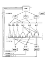
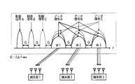
- FIG. 1 is a diagram illustrating a configuration example of a wireless communication system according to the present invention.
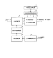
- FIG. 2 is a diagram illustrating a configuration example of a base station 10.
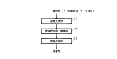
- FIG. 3 is a diagram illustrating a configuration example of relay stations A, B, and C.
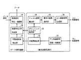
- FIG. 3 is a diagram illustrating a configuration example of terminal stations 1, 2, and 3.
- FIG. 3 is a diagram illustrating a frame format of a downlink control signal.
- FIG. 3 is a diagram illustrating a frame format of an uplink control signal. It is a flowchart which shows the example of a processing procedure of the base station 10 and terminal stations 1, 2, and 3 in this invention. It is a figure showing other allocation patterns in the present invention. It is a figure showing other allocation patterns in the present invention. It is a figure showing other allocation patterns in the present invention. It is a figure showing other allocation patterns in the present invention. It is a figure showing other allocation patterns in the present invention.
- FIG. 1 shows a configuration example of a wireless communication system of the present invention.
- the wireless communication system includes one base station 10, a plurality of moving relay stations A, B, C,..., X, and a plurality of (here, three) terminal stations 1 in a service area.
- a downlink configured to perform multiplex transmission to a plurality of terminal stations in a service area by the FDMA method and to perform MIMO (spatial multiplex) transmission only to terminal stations capable of equalizing / separating for each frequency band. It is a multiple access configuration.
- Each terminal station has one or more antennas.
- the terminal stations 1, 2, and 3 have 1, 2, and 3 antennas, respectively, and the terminal station 2 having two or more antennas. , 3 are available for MIMO transmission.
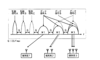
- the control signal and the data signal are arranged in different frequency bands, the frequency band of the control signal is fixed and known by the terminal station, and the frequency bands W1, W2 and W3 of the data signal are dynamic. Can be changed.
- the relay stations A, B, and C correspond one-to-one with the alphabets of the control signals A, B, and C and the data signals A, B, and C. Shall be transmitted.
- the base station 10 knows the position information of the relay stations A to X, and identifies a receivable relay station in the service area based on the position of each relay station. Here, it is assumed that signals transmitted by the three relay stations A, B, and C can be received within the service area.
- the base station 10 grasps the current position of each relay station from the orbit information. In the case of a relay station moving on the ground, the base station 10 obtains the position information obtained by each relay station using GPS or the like via a ground network.
- the base station 10 transmits control signals A, B, and C allocated to different frequency bands from the relay stations A, B, and C that can be received in the service area.
- the terminal stations 1, 2, and 3 in the service area receive the control signals receivable among the control signals A, B, and C transmitted from the relay stations A, B, and C, and perform synchronization processing. Know the possible relay stations and their number.
- channel information between the relay station and the terminal station is estimated using a synchronized control signal, and information on a receivable relay station and a relay station requesting MIMO transmission are optionally determined based on the channel information.
- the base station 10 allocates the required relay station of each terminal station and the frequency band of the data signal, notifies the information to each terminal station using a control signal, and starts MIMO transmission via the corresponding relay station.
- the signal addressed to the terminal station 1 is transmitted from the relay station A in the frequency band W1.
- the signal addressed to the terminal station 2 is transmitted by MIMO in the frequency band W2 from the relay stations A and B.
- the signal addressed to the terminal station 3 is transmitted by MIMO in the frequency band W3 from the relay stations A, B, and C.
- the relay stations A, B, and C basically have only a function of relaying and transmitting signals received from the base station 10 in a receivable state to the terminal stations 1, 2, and 3 by performing frequency conversion, amplification, and the like. .
- the control signal and the data signal are generated from the same baseband signal, it is assumed that the signals are synchronized. For this reason, it is assumed that the data signal can also be synchronized by the synchronization using the control signal, and the terminal station receives and equalizes the data signal according to the notified information, and demodulates the data. Further, a weighting matrix for equalizing the MIMO signal is calculated from the channel information of the control signal, the spatially multiplexed signal of each relay station is separated, and the data is demodulated.
- the relay station is a communication in a line-of-sight environment like a satellite and has channel characteristics with low frequency selectivity, it is assumed that synchronization / channel information by a control signal can be reflected in data signal equalization. At this time, by setting the guard band (G in the figure) between the FDMA signals to a value twice the maximum Doppler frequency ⁇ fmax assumed in the system, it is possible to avoid inter-carrier interference.
- FIG. 2 shows a configuration example of the base station 10.
- the base station 10 includes a relay station position calculator 11 and a relay station frequency band allocator 12, and performs frequency allocation of downlink control signals according to the position of each relay station.
- the base station 10 further includes a downlink control signal / data signal generator 13, an uplink control signal receiver 14, a terminal station detector 15, a required relay station detector 16, and a relay station selector 17.
- FIG. 3 shows a configuration example of the relay stations A, B, and C.
- the relay stations A, B, and C include a signal receiving unit 21, a frequency conversion / amplification unit 22, and a signal transmitting unit 23.
- the relay stations A, B, and C of the wireless communication system basically have a function of receiving a signal from the base station 10 and performing only frequency conversion and signal amplification for transmission to the terminal stations 1, 2, and 3.
- FIG. 4 shows a configuration example of the terminal stations 1, 2, and 3.
- terminal stations 1, 2, and 3 include a downlink control signal receiving / synchronizing unit 31, a relay station detecting unit 32, a downlink channel estimating unit 33, a channel correlation calculating unit 34, a request relay station selecting unit 35, an uplink control It includes a signal generation unit 36, a target terminal station detection unit 37, a reception equalization matrix generation unit 38, and a reception signal equalization / demodulation unit 39.
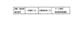
- FIG. 5 shows a frame format of the downlink control signal.
- the downlink control signal includes a known signal for synchronization / estimation, a relay station ID, a target terminal station ID, and data signal frequency band information.
- a relay station is selected for the terminal station, a frequency band for transmitting a data signal is allocated, and a downlink control signal and a data signal are transmitted.
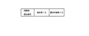
- FIG. 6 shows a frame format of the uplink control signal.
- the uplink control signal includes a known signal for synchronization, a terminal station ID, and a request relay station ID.
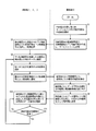
- FIG. 7 shows a processing procedure example of the base station 10 and the terminal stations 1, 2, and 3 in the present invention.
- relay stations A, B, and C exist at positions in the service area where communication with terminal stations 1, 2, and 3 is possible.
- the relay station position calculation unit 11 of the base station 10 can receive within the service area of the wireless communication system based on the position of each relay station calculated from known orbit information, for example.
- the relay stations A, B, and C are identified (S1).
- the relay station frequency band allocator 12 of the base station 10 transmits the downlink control signals A, B, and C of FIG. 1 so that the downlink control signals A, B, and C transmitted from the relay stations A, B, and C do not interfere with each other. Assigned to different frequency bands like C.
- the downlink control signal / data signal generation unit 13 of the base station 10 generates a downlink control signal unique to each relay station and transmits it to the service area via the relay stations A, B, and C (S2).
- the terminal stations 1, 2, and 3 in the service area respectively receive downlink control signals A, B, and C transmitted from the relay stations A, B, and C by the downlink control signal reception / synchronization unit 31.
- a signal is received, and a synchronization process is performed to obtain control information (S3).
- the terminal station 1 can receive the downlink control signal A of the relay station A, and the terminal stations 2 and 3 can receive the downlink control signals A, B, and C of the relay stations A, B, and C.
- the relay station detectors 32 of the terminal stations 1, 2, 3 detect a relay station based on the relay station ID of the downlink control signal that has been successfully received and synchronized, and the downlink channel estimator 33 detects the downlink control signal.
- the channel information of the detected downlink between each relay station and the terminal station is estimated using the signal (S4).
- the channel correlation calculation section 34 calculates the correlation from the channel information of each relay station, and the request relay station selection section 35 selects a relay station having a low channel correlation and requesting MIMO transmission (S5).
- the presence or absence of MIMO transmission may be set based on the value of the determinant det
- the relay station 2 in FIG. 1 can receive the downlink control signals A, B, and C transmitted from the relay stations A, B, and C, but the correlation between the relay stations B and C is high, the relay station It is also possible to request a MIMO transmission by selecting a combination of A and B (example of FIG. 1) or relay stations A and C (example of FIG. 8 described later). Further, since the number of antennas owned by the terminal stations 1 and 2 is less than the number of relay stations, it is necessary to select a relay station equal to or less than the number of antennas of the terminal station.
- the uplink control signal generator 36 of each of the terminal stations 1, 2, 3 adds the requested relay station information to the requested relay station ID of the uplink control signal and notifies the base station 10 (S6).
- the notification method at this time may be any method, and may be via any relay station concerned or via another transmission means.
- the uplink control signal receiving unit 14 of the base station 10 receives the uplink control signals from each of the terminal stations 1, 2, 3, and detects the terminal station ID by the terminal station detecting unit 15;
- the terminal station detects a request relay station requesting MIMO transmission (S7).
- the relay station selector 17 assigns a frequency band and a relay station that transmits the data signal of each of the relay stations 1, 2, and 3, based on the request relay stations collected from each of the terminal stations 1, 2, and 3 (S8).
- the downlink control signal / data signal generator 13 of the base station 10 generates a data signal addressed to the terminal stations 1, 2, and 3 to be transmitted in the frequency bands of the relay stations A, B, and C selected by the relay station selector 17. Further, it generates downlink control signals indicating the correspondence between the data signals addressed to the terminal stations 1, 2, and 3 and the frequency bands, and transmits them to the terminal stations 1, 2, and 3 via the corresponding relay stations (S9).
- the data signal A transmitted from the relay station A is allocated to the frequency band W1.
- the data signal addressed to the terminal station 2 multiplexes the data signals A and B transmitted from the relay stations A and B into the frequency band W2 and performs MIMO transmission.
- the data signal addressed to the terminal station 3 is obtained by multiplexing the data signals A, B, and C transmitted from the relay stations A, B, and C into the frequency band W3 and performing MIMO transmission.
- the data signal addressed to the terminal station 2 is obtained by multiplexing the data signals A and C transmitted from the relay stations A and C into the frequency band W2 and performing MIMO transmission.
- the assignment of data signals to the terminal stations 1 and 3 is the same as in the example of FIG.
- FIG. 9 is a case where each of the terminal stations 1, 2, and 3 is provided with three antennas and is a request relay station A, B, or C, respectively. Data signals addressed to the terminal stations 1, 2, and 3 are relayed. The data signals A, B, and C transmitted from the stations A, B, and C are multiplexed in the frequency bands W1, W2, and W3, respectively, and transmitted by MIMO.
- the number of antennas of the terminal stations 1, 2, 3 is 1, and there is no terminal station capable of MIMO transmission.
- the data signal addressed to the terminal station 1 is the data transmitted from the relay station A.
- the signal A is assigned to the frequency band W1
- the data signal addressed to the terminal station 2 is assigned to the data signal B transmitted from the relay station B to the frequency band W2
- the data signal addressed to the terminal station 3 is assigned to the data transmitted from the relay station C.
- the signal C is assigned to the frequency band W3.
- the number of terminal stations is larger than that of relay stations, it is possible to cope by adopting a multiple access system such as TDMA for each frequency band.
- a method of controlling the allocation of the frequency band according to the distribution of the number of required relay stations can be considered.
- the target terminal station detector 37 of each of the terminal stations 1, 2, 3 detects a downlink control signal for the own station from the downlink control signals A, B, C, and the reception equalization matrix generator 38 generates a downlink channel estimator 33.
- a reception weight matrix is generated by using the estimated channel information, and the reception signal equalization / demodulation section 39 performs reception equalization of the data signal addressed to the own station by using the reception weight matrix, and demodulates (S10).
- terminal stations 1, 2, and 3 sequentially monitor the downlink control signal of the base station 10 and change the receivable request relay station along with the movement of the relay station or the terminal station as in step S3. Returns to step S4 and makes a request again (S11).
- the terminal stations in the service area know the center frequency of the downlink control signal, but the relay station that transmits the downlink control signal receives the relay station ID of the downlink control signal described in FIG. Figure out.
Landscapes
- Engineering & Computer Science (AREA)
- Computer Networks & Wireless Communication (AREA)
- Signal Processing (AREA)
- Physics & Mathematics (AREA)
- Astronomy & Astrophysics (AREA)
- Aviation & Aerospace Engineering (AREA)
- General Physics & Mathematics (AREA)
- Mobile Radio Communication Systems (AREA)
- Radio Relay Systems (AREA)
Abstract
1台の基地局と、移動する複数の中継局と、サービスエリア内の複数の端末局とを備え、基地局から1または複数の中継局を介して各端末局に対してダウンリンク多元接続を行う無線通信システムにおいて、基地局は、複数の中継局の位置に基づき、各中継局が送信する信号をサービスエリアで受信可能な中継局を識別し、該中継局を介して各端末局に対してそれぞれ異なる周波数帯域でデータ信号を周波数多重伝送するとともに、空間多重伝送に対応する端末局に対して特定の周波数帯域と複数の中継局を介してデータ信号を空間多重伝送するダウンリンク多元接続手段を備える。
Description
本発明は、1つの基地局と、移動する複数の中継局と、複数の端末局で構成され、基地局と各端末局が接続可能な1以上の中継局を介してダウンリンク多元接続を行う無線通信システム、無線通信方法および基地局装置に関する。
低軌道衛星(LEO)システムは、静止衛星に比べて低軌道( 800~2000km)の衛星を用いて通信を行うことで、静止軌道(高度約36,000km)の静止衛星(GEO)システムと比較して、通信の特徴が低遅延・低減衰量となる長所がある。一方で地球局から見て常時衛星の軌道が変わるものであるため、複数の衛星を用いた衛星コンステレーションの形成によってサービスエリアを構築する必要がある。そのため端末局から複数衛星が受信可能な状況が多くなる。
(従来例1)
非特許文献1によると、LEOシステムは、一つのサービスエリアに異なる周波数帯域を割り当てたLEO衛星を複数配備し、各端末局は受信可能領域に存在する複数の衛星の中で最も条件の良い、例えば受信電力の高い衛星を選択していくハンドオーバー制御の方法がとられている。これにより衛星数が多いほど端末局との接続性を向上させることが可能である。一方、複数の衛星に周波数を割り当てることによって生じる周波数利用効率の低下が問題となる。一つのサービスエリア内で利用される周波数帯域は想定される衛星数分に分割される必要があるため、衛星数が多いほど一衛星あたりに割り当てられる帯域幅が減少する。さらにLEOシステムは端末局から見て相対的な移動速度が高速であり、多大なドップラーシフトを受けることから、隣接帯域とのガードバンドは大きな周波数偏差を考慮して設定する必要があり、周波数利用効率をさらに低下させる要因となる。
非特許文献1によると、LEOシステムは、一つのサービスエリアに異なる周波数帯域を割り当てたLEO衛星を複数配備し、各端末局は受信可能領域に存在する複数の衛星の中で最も条件の良い、例えば受信電力の高い衛星を選択していくハンドオーバー制御の方法がとられている。これにより衛星数が多いほど端末局との接続性を向上させることが可能である。一方、複数の衛星に周波数を割り当てることによって生じる周波数利用効率の低下が問題となる。一つのサービスエリア内で利用される周波数帯域は想定される衛星数分に分割される必要があるため、衛星数が多いほど一衛星あたりに割り当てられる帯域幅が減少する。さらにLEOシステムは端末局から見て相対的な移動速度が高速であり、多大なドップラーシフトを受けることから、隣接帯域とのガードバンドは大きな周波数偏差を考慮して設定する必要があり、周波数利用効率をさらに低下させる要因となる。
(従来例2)
これに対し、複数の衛星を同じ帯域で利用し、信号処理によって分離させる方法が検討されている。非特許文献2によると、複数の静止衛星と複数の受信アンテナを所有する端末局との間のMIMO(Multi-Input Multi-Output)伝送により、伝送容量向上のためのアンテナ配置最適化が検討されている。しかし、本検討では静止衛星を想定しているため、LEOシステムを想定した動的なドップラー周波数の影響は考慮されていない。
これに対し、複数の衛星を同じ帯域で利用し、信号処理によって分離させる方法が検討されている。非特許文献2によると、複数の静止衛星と複数の受信アンテナを所有する端末局との間のMIMO(Multi-Input Multi-Output)伝送により、伝送容量向上のためのアンテナ配置最適化が検討されている。しかし、本検討では静止衛星を想定しているため、LEOシステムを想定した動的なドップラー周波数の影響は考慮されていない。
(従来例3)
一方、地上無線通信では、複数の中継局(RRH)を用いた多重伝送としてCoMP(Coordinated multipoint)という技術がある。非特許文献3では、基地局(eNodeB)が、自局アンテナかRRHを用いて協調伝送を行う技術であるが、基地局とRRHの接続手段は光ファイバー等の有線接続が前提となっているため、送信時に予め周波数同期を行うことが可能である。一方で今回想定しているLEO衛星を用いたMIMO伝送では、衛星同士の同期手段も無線を経由せざるを得ない環境であるのに加え、LEOシステムは衛星(中継局)と端末局の相対関係によって異なる相対速度となるため、多元接続において時間・周波数同期を事前に行うことは困難である。
一方、地上無線通信では、複数の中継局(RRH)を用いた多重伝送としてCoMP(Coordinated multipoint)という技術がある。非特許文献3では、基地局(eNodeB)が、自局アンテナかRRHを用いて協調伝送を行う技術であるが、基地局とRRHの接続手段は光ファイバー等の有線接続が前提となっているため、送信時に予め周波数同期を行うことが可能である。一方で今回想定しているLEO衛星を用いたMIMO伝送では、衛星同士の同期手段も無線を経由せざるを得ない環境であるのに加え、LEOシステムは衛星(中継局)と端末局の相対関係によって異なる相対速度となるため、多元接続において時間・周波数同期を事前に行うことは困難である。
(従来例4)
非特許文献4は、MIMO伝送を行う複数の衛星(中継局)の周波数非同期性に着目し、ロング・分散プリアンブルを用いたチャネル推定、タイミング検出方法を提案している。
非特許文献4は、MIMO伝送を行う複数の衛星(中継局)の周波数非同期性に着目し、ロング・分散プリアンブルを用いたチャネル推定、タイミング検出方法を提案している。
伊藤泰彦監修,"低軌道衛星通信システム,"電子通信学会,1999.
R.T. Schworz, A. Knopp, D. Ogermann, C.A. Hofmann, B. Lankl,"Optimum-capacity MIMO satellite link for fixed and mobile services, " in Int. ITG Work. Smart Antennas, WSA 2008, pp.209-216, Feb. 2008.
S. Sun, Q. Gao, Y. Peng, Y. Wang, and L. Song,"Interference management through CoMP in 3GPP LTE- advanced networks," IEEE Wireless Communications, vol.20, no.1, pp.59-66, 2013.
五藤大介,山下史洋,"複数衛星マルチビームMIMOシステムにおけるユニークワードチャネル推定を用いた伝送容量評価,"電子情報通信学会技術研究報告,SAT ,衛星通信,vol.117 ,no.174,pp.69-74,Aug. 2017 .
従来例4では、同じ周波数帯域で同期することを前提としているため、チャネル間干渉に伴うチャネル推定精度の低下を防ぐために多大なプリアンブル長が必要となり、周波数利用効率が低下する。さらに、本方式では静止衛星を想定しているため、あらかじめシステムで利用する衛星数を固定的に設定することが可能であるが、LEOシステムの場合は動的にサービスエリアで受信可能な衛星数が変動するため、多重する衛星数が通信環境によって変動するため、固定的に設定することが困難である。このことから、同サービスエリアだとしても、端末局の通信環境および端末性能に基づいて、多重する衛星数を動的に変更できる方法が望ましい。
本発明は、移動する複数の中継局を含む無線通信システムにおいて、基地局が端末局の受信可能な中継局数に基づいて空間多重伝送帯域を動的に設定することができる無線通信システム、無線通信方法および基地局装置を提供することを目的とする。
第1の発明は、1台の基地局と、移動する複数の中継局と、サービスエリア内の複数の端末局とを備え、基地局から1または複数の中継局を介して各端末局に対してダウンリンク多元接続を行う無線通信システムにおいて、基地局は、複数の中継局の位置に基づき、各中継局が送信する信号をサービスエリアで受信可能な中継局を識別し、該中継局を介して各端末局に対してそれぞれ異なる周波数帯域でデータ信号を周波数多重伝送するとともに、空間多重伝送に対応する端末局に対して特定の周波数帯域と複数の中継局を介してデータ信号を空間多重伝送するダウンリンク多元接続手段を備える。
第1の発明の無線通信システムにおいて、基地局のダウンリンク多元接続手段は、サービスエリアで受信可能な中継局から個別の周波数帯域で中継局IDを含む下り制御信号を送信する手段を含み、端末局は、受信可能な下り制御信号を受信して同期をとり、さらに同期をとった下り制御信号から中継局と端末局との間のチャネル情報を推定し、該チャネル情報に基づいて受信可能な1以上の中継局を選択して基地局に通知するダウンリンク多元接続手段を備え、基地局のダウンリンク多元接続手段は、端末局で選択された中継局を介して当該端末局宛のデータ信号を空間多重伝送する特定の周波数帯域を割り当て、その情報を下り制御信号により端末局に通知するとともに、当該端末局宛のデータ信号を空間多重伝送する手段を含む。
第1の発明の無線通信システムにおいて、端末局宛の下り制御信号とデータ信号は同じベースバンド信号から生成して同期しており、端末局のダウンリンク多元接続手段は、下り制御信号から推定したチャネル情報を用いて空間多重伝送されたデータ信号の分離および復調を行う手段を含む。
第1の発明の無線通信システムにおいて、端末局のダウンリンク多元接続手段は、中継局の下り制御信号を監視し、受信可能な中継局に変化があれば、空間多重伝送を要求する中継局を選択しなおして基地局に通知する構成である。
第2の発明は、1台の基地局と、移動する複数の中継局と、サービスエリア内の複数の端末局とを備え、基地局から1または複数の中継局を介して各端末局に対してダウンリンク多元接続を行う無線通信方法において、基地局のダウンリンク多元接続手段は、複数の中継局の位置に基づき、各中継局が送信する信号をサービスエリアで受信可能な中継局を識別し、該中継局を介して各端末局に対してそれぞれ異なる周波数帯域でデータ信号を周波数多重伝送するとともに、空間多重伝送に対応する端末局に対して特定の周波数帯域と複数の中継局を介してデータ信号を空間多重伝送する。
第2の発明の無線通信方法において、基地局のダウンリンク多元接続手段は、サービスエリアで受信可能な中継局から個別の周波数帯域で中継局IDを含む下り制御信号を送信する処理を行い、端末局のダウンリンク多元接続手段は、受信可能な下り制御信号を受信して同期をとり、さらに同期をとった下り制御信号から中継局と端末局との間のチャネル情報を推定し、該チャネル情報に基づいて受信可能な1以上の中継局を選択して基地局に通知する処理を行い、基地局のダウンリンク多元接続手段は、端末局で選択された中継局を介して当該端末局宛のデータ信号を空間多重伝送する特定の周波数帯域を割り当て、その情報を下り制御信号により端末局に通知するとともに、当該端末局宛のデータ信号を空間多重伝送する。
第2の発明の無線通信方法において、端末局宛の下り制御信号とデータ信号は同じベースバンド信号から生成して同期しており、端末局のダウンリンク多元接続手段は、下り制御信号から推定したチャネル情報を用いて空間多重伝送されたデータ信号の分離および復調を行う。
第3の発明は、1台の基地局と、移動する複数の中継局と、サービスエリア内の複数の端末局とを備え、基地局から1または複数の中継局を介して各端末局に対してダウンリンク多元接続を行う無線通信システムの基地局装置において、複数の中継局の位置に基づき、各中継局が送信する信号をサービスエリアで受信可能な中継局を識別し、該中継局を介して各端末局に対してそれぞれ異なる周波数帯域でデータ信号を周波数多重伝送するとともに、空間多重伝送に対応する端末局に対して特定の周波数帯域と複数の中継局を介してデータ信号を空間多重伝送するダウンリンク多元接続手段を備える。
本発明は、移動する複数の中継局を含む無線通信システムにおいて、基地局が端末局の受信可能な中継局数に基づいてMIMO伝送帯域を動的に設定することで、可能な限り複数の中継局で空間多重伝送する周波数帯域をシェアすることが可能となり、周波数利用効率の向上を期待できる。
<システム構成>
図1は、本発明の無線通信システムの構成例を示す。
図1において、本無線通信システムは、1台の基地局10と、移動する複数の中継局A,B,C,…,Xと、サービスエリアの複数(ここでは3台)の端末局1,2,3により構成され、サービスエリアの複数の端末局に対してFDMA方式で多重伝送するとともに、周波数帯域ごとに等化・分離が可能な端末局にのみMIMO(空間多重)伝送を行うダウンリンク多元接続構成である。各端末局は1~複数のアンテナを備え、ここでは簡単のため、端末局1,2,3は、それぞれアンテナを1,2,3本備えており、2本以上のアンテナを有する端末局2,3に対してMIMO伝送が可能になっている。
図1は、本発明の無線通信システムの構成例を示す。
図1において、本無線通信システムは、1台の基地局10と、移動する複数の中継局A,B,C,…,Xと、サービスエリアの複数(ここでは3台)の端末局1,2,3により構成され、サービスエリアの複数の端末局に対してFDMA方式で多重伝送するとともに、周波数帯域ごとに等化・分離が可能な端末局にのみMIMO(空間多重)伝送を行うダウンリンク多元接続構成である。各端末局は1~複数のアンテナを備え、ここでは簡単のため、端末局1,2,3は、それぞれアンテナを1,2,3本備えており、2本以上のアンテナを有する端末局2,3に対してMIMO伝送が可能になっている。
中継局からのダウンリンクの信号は、制御信号とデータ信号を異なる周波数帯域に配置し、制御信号の周波数帯域は固定かつ端末局で既知であり、データ信号の周波数帯域W1,W2,W3は動的に変更可能とする。ここで、中継局A,B,Cと、制御信号A,B,Cおよびデータ信号A,B,Cのアルファベットは1対1で対応しており、中継局Aは制御信号Aとデータ信号Aを送信することとする。
基地局10は、中継局A~Xの位置情報を把握しており、各中継局の位置に基づいてサービスエリア内で受信可能な中継局を識別する。ここでは、3台の中継局A,B,Cが送信する信号がサービスエリア内で受信可能とする。なお、中継局が所定の軌道を移動する人工衛星の場合には、基地局10はその軌道情報から各中継局の現在位置を把握する。地上を移動する中継局の場合には、基地局10は各中継局がGPS等を利用して取得した位置情報を地上ネットワークを介して入手する。
基地局10は、サービスエリア内で受信可能な中継局A,B,Cから、互いに異なる周波数帯域に割り当てた制御信号A,B,Cを送信する。一方、サービスエリアの端末局1,2,3は、中継局A,B,Cから送信された制御信号A,B,Cのうち受信可能な制御信号を受信して同期処理を行い、それぞれ受信可能な中継局とその数を把握する。さらに、同期をとった制御信号を用いて当該中継局と端末局との間のチャネル情報を推定し、受信可能な中継局とそのチャネル情報に基づいてMIMO伝送を要求する中継局の情報を任意のアップリンクを介して基地局10に通知する。
基地局10は、各端末局の要求中継局とデータ信号の周波数帯域を割り当て、その情報を制御信号を用いて各端末局に通知するとともに、対応する中継局を介してMIMO伝送を開始する。図1の例では、端末局1宛の信号は、中継局Aから周波数帯域W1で送信される。端末局2宛の信号は、中継局A,Bから周波数帯域W2でMIMO伝送される。端末局3宛の信号は、中継局A,B,Cから周波数帯域W3でMIMO伝送される。中継局A,B,Cは、基本的に基地局10から受信した信号を周波数変換および増幅などを行うことで、端末局1,2,3に受信可能な状態で中継伝送する機能のみを有する。
なお、制御信号とデータ信号は同じベースバンド信号から生成されるため、信号間は同期しているものとする。このため、制御信号を用いた同期によってデータ信号も同期できるものとし、端末局は通知された情報に従ってデータ信号の受信、等化処理を行ってデータを復調する。さらに、制御信号のチャネル情報からMIMO信号の等化のための重み行列を算出し、空間多重された各中継局の信号を分離し、データを復調する。また、中継局が衛星のように見通し環境での通信であり、周波数選択性が小さいチャネル特性を有する場合は、制御信号による同期・チャネル情報をデータ信号の等化に反映できるものとする。このとき、各FDMA信号間のガードバンド(図中G)は、システムで想定される最大ドップラー周波数Δfmaxの2倍の値に設定することで、キャリア間干渉を回避することが可能である。
<基地局10の構成>
図2は、基地局10の構成例を示す。
図2において、基地局10は、中継局位置算出部11、中継局周波数帯域割当部12を備え、各中継局の位置に応じて、下り制御信号の周波数割当を行う。基地局10は、さらに、下り制御信号・データ信号生成部13、上り制御信号受信部14、端末局検出部15、要求中継局検出部16、中継局選択部17を備える。
図2は、基地局10の構成例を示す。
図2において、基地局10は、中継局位置算出部11、中継局周波数帯域割当部12を備え、各中継局の位置に応じて、下り制御信号の周波数割当を行う。基地局10は、さらに、下り制御信号・データ信号生成部13、上り制御信号受信部14、端末局検出部15、要求中継局検出部16、中継局選択部17を備える。
<中継局A,B,Cの構成>
図3は、中継局A,B,Cの構成例を示す。
図3において、中継局A,B,Cは、信号受信部21、周波数変換・増幅部22、信号送信部23を備える。本無線通信システムの中継局A,B,Cは、基本的に基地局10からの信号を受信し、端末局1,2,3に送信するための周波数変換および信号増幅のみ行う機能を有する。
図3は、中継局A,B,Cの構成例を示す。
図3において、中継局A,B,Cは、信号受信部21、周波数変換・増幅部22、信号送信部23を備える。本無線通信システムの中継局A,B,Cは、基本的に基地局10からの信号を受信し、端末局1,2,3に送信するための周波数変換および信号増幅のみ行う機能を有する。
<端末局1,2,3の構成>
図4は、端末局1,2,3の構成例を示す。
図4において、端末局1,2,3は、下り制御信号受信・同期部31、中継局検出部32、ダウンリンクチャネル推定部33、チャネル相関算出部34、要求中継局選択部35、上り制御信号生成部36、対象端末局検出部37、受信等化行列生成部38、受信信号等化・復調部39を備える。
図4は、端末局1,2,3の構成例を示す。
図4において、端末局1,2,3は、下り制御信号受信・同期部31、中継局検出部32、ダウンリンクチャネル推定部33、チャネル相関算出部34、要求中継局選択部35、上り制御信号生成部36、対象端末局検出部37、受信等化行列生成部38、受信信号等化・復調部39を備える。
<下り制御信号、上り制御信号のフレームフォーマット>
図5は、下り制御信号のフレームフォーマットを示す。
図5において、下り制御信号は、同期・推定用既知信号、中継局ID、対象端末局ID、データ信号周波数帯域情報により構成される。ここでは、端末局から受信した上り制御信号に基づき、当該端末局への中継局の選定とデータ信号を送信する周波数帯域を割り当て、下り制御信号およびデータ信号の送信を行う。
図5は、下り制御信号のフレームフォーマットを示す。
図5において、下り制御信号は、同期・推定用既知信号、中継局ID、対象端末局ID、データ信号周波数帯域情報により構成される。ここでは、端末局から受信した上り制御信号に基づき、当該端末局への中継局の選定とデータ信号を送信する周波数帯域を割り当て、下り制御信号およびデータ信号の送信を行う。
図6は、上り制御信号のフレームフォーマットを示す。
図6において、上り制御信号は、同期用既知信号、端末局ID、要求中継局IDで構成される。
図6において、上り制御信号は、同期用既知信号、端末局ID、要求中継局IDで構成される。
<実施例>
図7は、本発明における基地局10および端末局1,2,3の処理手順例を示す。ここでは、図1に示すようにサービスエリア内の端末局1,2,3と通信可能な位置に中継局A,B,Cが存在するものとする。
図7は、本発明における基地局10および端末局1,2,3の処理手順例を示す。ここでは、図1に示すようにサービスエリア内の端末局1,2,3と通信可能な位置に中継局A,B,Cが存在するものとする。
図1~図4および図7において、基地局10の中継局位置算出部11は、例えば既知の軌道情報から算出された各中継局の位置に基づき、無線通信システムのサービスエリア内で受信可能な中継局A,B,Cを識別する(S1)。基地局10の中継局周波数帯域割当部12は、中継局A,B,Cから送信する下り制御信号A,B,Cが互いに干渉し合わないように、図1の下り制御信号A,B,Cのように異なる周波数帯域に割り当てる。基地局10の下り制御信号・データ信号生成部13は、各中継局固有の下り制御信号を生成し、中継局A,B,Cを介してサービスエリアに送信する(S2)。
当該サービスエリアの端末局1,2,3は、それぞれ下り制御信号受信・同期部31にて中継局A,B,Cから送信された下り制御信号A,B,Cのうち受信可能な下り制御信号を受信し、制御情報を取得するために同期処理を行う(S3)。例えば、図1の場合は、端末局1では中継局Aの下り制御信号Aを受信可能とし、端末局2,3では中継局A,B,Cの下り制御信号A,B,Cを受信可能とする。
端末局1,2,3の中継局検出部32は、受信および同期処理ができた下り制御信号の中継局IDに基づいて中継局を検出し、ダウンリンクチャネル推定部33で下り制御信号の既知信号を用いて、検出した各中継局と端末局との間のダウンリンクのチャネル情報を推定する(S4)。チャネル相関算出部34は、各中継局のチャネル情報から相関を計算し、要求中継局選択部35にてチャネル相関が低くMIMO伝送を要求する中継局を選択する(S5)。例えば、中継局A,B,Cと端末局3の3アンテナ間のチャネル情報で生成される3×3のチャネル行列をHとすると、行列式 det|H|が大きいほどチャネル相関が低くなり、伝送容量が大きくなる傾向があるため、端末局3でチャネル情報を推定して生成される行列H’の行列式 det|H’|の値に基づいてMIMO伝送の有無を設定してもよい。
また、必ずしも受信可能な中継局の全てを選択する必要はない。例えば、図1の端末局2において中継局A,B,Cから送信された下り制御信号A,B,Cが受信可能であるが、中継局BとCの相関が高くなる場合は、中継局AとB(図1の例)、または中継局AとC(後述する図8の例)の組み合わせを選択してMIMO伝送を要求することも可能である。また、端末局1,2は所有するアンテナ数が中継局数を下回っているため、端末局のアンテナ数以下の中継局の選択は必須となる。
端末局1,2,3の上り制御信号生成部36は、要求する中継局情報を上り制御信号の要求中継局IDに付与して基地局10に通知する(S6)。この時の通知方法は任意の方法でよく、任意の当該中継局を経由しても、別の送信手段を経由してもよい。
基地局10の上り制御信号受信部14は、各端末局1,2,3からの上り制御信号を受信し、端末局検出部15で端末局IDを検出し、要求中継局検出部16で当該端末局がMIMO伝送を要求している要求中継局を検出する(S7)。中継局選択部17は、各端末局1,2,3から収集した要求中継局に基づき、各中継局1,2,3のデータ信号を送信する中継局と周波数帯域を割り当てる(S8)。
基地局10の下り制御信号・データ信号生成部13は、中継局選択部17で選択した中継局A,B,Cの周波数帯域で送信する端末局1,2,3宛のデータ信号を生成し、さらに端末局1,2,3宛のデータ信号と周波数帯域の対応を示す下り制御信号を生成し、それぞれ対応する中継局を介して各端末局1,2,3に送信する(S9)。
図1の例では、端末局1宛のデータ信号は、中継局Aから送信するデータ信号Aを周波数帯域W1に割り当てる。端末局2宛のデータ信号は、中継局A,Bから送信するデータ信号A,Bを周波数帯域W2に多重し、MIMO送信する。端末局3宛のデータ信号は、中継局A,B,Cから送信するデータ信号A,B,Cを周波数帯域W3に多重し、MIMO伝送する。
図8の例では、端末局2宛のデータ信号は、中継局A,Cから送信するデータ信号A,Cを周波数帯域W2に多重し、MIMO伝送する。端末局1,3宛のデータ信号の割り当ては図1の例と同じである。
図9の例は、端末局1,2,3がそれぞれ3アンテナを備え、かつそれぞれ要求中継局A,B,Cとした場合であり、端末局1,2,3宛のデータ信号は、中継局A,B,Cから送信するデータ信号A,B,Cをそれぞれ周波数帯域W1,W2,W3に多重し、MIMO伝送する。
図10の例は、端末局1,2,3のアンテナ数が1であり、MIMO伝送ができる端末局が存在しない場合であり、端末局1宛のデータ信号は、中継局Aから送信するデータ信号Aを周波数帯域W1に割り当て、端末局2宛のデータ信号は、中継局Bから送信するデータ信号Bを周波数帯域W2に割り当て、端末局3宛のデータ信号は、中継局Cから送信するデータ信号Cを周波数帯域W3に割り当てる。
また、端末局の数が中継局より多い場合は、各周波数帯域をTDMAなどの多元接続方式を採用することで対応が可能である。この場合は要求中継局数の分布に従って周波数帯域の割当を制御する方法が考えられる。
端末局1,2,3の対象端末局検出部37は、下り制御信号A,B,Cから自局向けの下り制御信号を検出し、受信等化行列生成部38でダウンリンクチャネル推定部33が推定したチャネル情報を用いて受信重み行列を生成し、受信信号等化・復調部39でその受信重み行列を用いて自局宛のデータ信号の受信等化を行い、復調する(S10)。
さらに、端末局1,2,3は、ステップS3と同様に、逐次基地局10の下り制御信号をモニタリングし、中継局や端末局の移動などに伴って受信可能な要求中継局を変更する場合は、ステップS4に戻って再度要求を行う(S11)。
なお、サービスエリア内の端末局は、下り制御信号の中心周波数を既知とするが、当該下り制御信号を送信する中継局は、図5に記載の下り制御信号の中継局IDを受信することで把握する。
1,2,3 端末局
10 基地局
A,B,C 中継局
11 中継局位置算出部
12 中継局周波数帯域割当部
13 下り制御信号・データ信号生成部
14 上り制御信号受信部
15 端末局検出部
16 要求中継局検出部
17 中継局選択部
21 信号受信部
22 周波数変換・増幅部
23 信号送信部
31 下り制御信号受信・同期部
32 中継局検出部
33 ダウンリンクチャネル推定部
34 チャネル相関算出部
35 要求中継局選択部
36 上り制御信号生成部
37 対象端末局検出部
38 受信等化行列生成部
39 受信信号等化・復調部
10 基地局
A,B,C 中継局
11 中継局位置算出部
12 中継局周波数帯域割当部
13 下り制御信号・データ信号生成部
14 上り制御信号受信部
15 端末局検出部
16 要求中継局検出部
17 中継局選択部
21 信号受信部
22 周波数変換・増幅部
23 信号送信部
31 下り制御信号受信・同期部
32 中継局検出部
33 ダウンリンクチャネル推定部
34 チャネル相関算出部
35 要求中継局選択部
36 上り制御信号生成部
37 対象端末局検出部
38 受信等化行列生成部
39 受信信号等化・復調部
Claims (8)
- 1台の基地局と、移動する複数の中継局と、サービスエリア内の複数の端末局とを備え、基地局から1または複数の中継局を介して各端末局に対してダウンリンク多元接続を行う無線通信システムにおいて、
前記基地局は、前記複数の中継局の位置に基づき、各中継局が送信する信号を前記サービスエリアで受信可能な中継局を識別し、該中継局を介して各端末局に対してそれぞれ異なる周波数帯域でデータ信号を周波数多重伝送するとともに、空間多重伝送に対応する端末局に対して特定の周波数帯域と複数の中継局を介してデータ信号を空間多重伝送するダウンリンク多元接続手段を備えた
ことを特徴とする無線通信システム。 - 請求項1に記載の無線通信システムにおいて、
前記基地局のダウンリンク多元接続手段は、前記サービスエリアで受信可能な中継局から個別の周波数帯域で中継局IDを含む下り制御信号を送信する手段を含み、
前記端末局は、受信可能な前記下り制御信号を受信して同期をとり、さらに同期をとった下り制御信号から中継局と端末局との間のチャネル情報を推定し、該チャネル情報に基づいて受信可能な1以上の中継局を選択して前記基地局に通知するダウンリンク多元接続手段を備え、
前記基地局のダウンリンク多元接続手段は、前記端末局で選択された中継局を介して当該端末局宛のデータ信号を空間多重伝送する前記特定の周波数帯域を割り当て、その情報を前記下り制御信号により前記端末局に通知するとともに、当該端末局宛のデータ信号を空間多重伝送する手段を含む
ことを特徴とする無線通信システム。 - 請求項2に記載の無線通信システムにおいて、
前記端末局宛の下り制御信号とデータ信号は同じベースバンド信号から生成して同期しており、
前記端末局のダウンリンク多元接続手段は、前記下り制御信号から推定したチャネル情報を用いて前記空間多重伝送されたデータ信号の分離および復調を行う手段を含む
ことを特徴とする無線通信システム。 - 請求項2に記載の無線通信システムにおいて、
前記端末局のダウンリンク多元接続手段は、前記中継局の前記下り制御信号を監視し、前記受信可能な中継局に変化があれば、前記空間多重伝送を要求する中継局を選択しなおして前記基地局に通知する構成である
ことを特徴とする無線通信システム。 - 1台の基地局と、移動する複数の中継局と、サービスエリア内の複数の端末局とを備え、基地局から1または複数の中継局を介して各端末局に対してダウンリンク多元接続を行う無線通信方法において、
前記基地局のダウンリンク多元接続手段は、前記複数の中継局の位置に基づき、各中継局が送信する信号を前記サービスエリアで受信可能な中継局を識別し、該中継局を介して各端末局に対してそれぞれ異なる周波数帯域でデータ信号を周波数多重伝送するとともに、空間多重伝送に対応する端末局に対して特定の周波数帯域と複数の中継局を介してデータ信号を空間多重伝送する
ことを特徴とする無線通信方法。 - 請求項5に記載の無線通信方法において、
前記基地局のダウンリンク多元接続手段は、前記サービスエリアで受信可能な中継局から個別の周波数帯域で中継局IDを含む下り制御信号を送信する処理を行い、
前記端末局のダウンリンク多元接続手段は、受信可能な前記下り制御信号を受信して同期をとり、さらに同期をとった下り制御信号から中継局と端末局との間のチャネル情報を推定し、該チャネル情報に基づいて受信可能な1以上の中継局を選択して前記基地局に通知する処理を行い、
前記基地局のダウンリンク多元接続手段は、前記端末局で選択された中継局を介して当該端末局宛のデータ信号を空間多重伝送する前記特定の周波数帯域を割り当て、その情報を前記下り制御信号により前記端末局に通知するとともに、当該端末局宛のデータ信号を空間多重伝送する
ことを特徴とする無線通信方法。 - 請求項6に記載の無線通信方法において、
前記端末局宛の下り制御信号とデータ信号は同じベースバンド信号から生成して同期しており、
前記端末局のダウンリンク多元接続手段は、前記下り制御信号から推定したチャネル情報を用いて前記空間多重伝送されたデータ信号の分離および復調を行う
ことを特徴とする無線通信方法。 - 1台の基地局と、移動する複数の中継局と、サービスエリア内の複数の端末局とを備え、基地局から1または複数の中継局を介して各端末局に対してダウンリンク多元接続を行う無線通信システムの基地局装置において、
前記複数の中継局の位置に基づき、各中継局が送信する信号を前記サービスエリアで受信可能な中継局を識別し、該中継局を介して各端末局に対してそれぞれ異なる周波数帯域でデータ信号を周波数多重伝送するとともに、空間多重伝送に対応する端末局に対して特定の周波数帯域と複数の中継局を介してデータ信号を空間多重伝送するダウンリンク多元接続手段を備えた
ことを特徴とする基地局装置。
Priority Applications (1)
| Application Number | Priority Date | Filing Date | Title |
|---|---|---|---|
| US17/254,845 US11683089B2 (en) | 2018-06-25 | 2019-06-19 | Radio communication system, radio communication method, and base station device |
Applications Claiming Priority (2)
| Application Number | Priority Date | Filing Date | Title |
|---|---|---|---|
| JP2018-120036 | 2018-06-25 | ||
| JP2018120036A JP7107022B2 (ja) | 2018-06-25 | 2018-06-25 | 無線通信システム、無線通信方法および基地局装置 |
Publications (1)
| Publication Number | Publication Date |
|---|---|
| WO2020004187A1 true WO2020004187A1 (ja) | 2020-01-02 |
Family
ID=68987132
Family Applications (1)
| Application Number | Title | Priority Date | Filing Date |
|---|---|---|---|
| PCT/JP2019/024340 Ceased WO2020004187A1 (ja) | 2018-06-25 | 2019-06-19 | 無線通信システム、無線通信方法および基地局装置 |
Country Status (3)
| Country | Link |
|---|---|
| US (1) | US11683089B2 (ja) |
| JP (1) | JP7107022B2 (ja) |
| WO (1) | WO2020004187A1 (ja) |
Cited By (2)
| Publication number | Priority date | Publication date | Assignee | Title |
|---|---|---|---|---|
| CN114025309A (zh) * | 2021-09-17 | 2022-02-08 | 中时讯通信建设有限公司 | 一种5g频段的mimo的物联网组网方法及系统 |
| JPWO2023139679A1 (ja) * | 2022-01-19 | 2023-07-27 |
Families Citing this family (6)
| Publication number | Priority date | Publication date | Assignee | Title |
|---|---|---|---|---|
| JP7410509B2 (ja) * | 2020-02-03 | 2024-01-10 | 日本電信電話株式会社 | 受信局、無線通信システム、及び無線通信方法 |
| US12470257B2 (en) * | 2020-12-02 | 2025-11-11 | Ntt, Inc. | Doppler shift compensation apparatus and doppler shift compensation method |
| US12463712B2 (en) * | 2020-12-25 | 2025-11-04 | Ntt, Inc. | Relay apparatus and relay method |
| US11800422B2 (en) * | 2021-01-12 | 2023-10-24 | Cisco Technology, Inc. | Optimization of communications in a low earth orbit (LEO) satellite network |
| US11711742B2 (en) * | 2021-02-24 | 2023-07-25 | Qualcomm Incorporated | Relay selection for cooperative relaying |
| US12580670B2 (en) * | 2022-01-19 | 2026-03-17 | Ntt, Inc. | Wireless communication system, wireless communication method, and wireless device |
Citations (2)
| Publication number | Priority date | Publication date | Assignee | Title |
|---|---|---|---|---|
| US20170359117A1 (en) * | 2015-12-11 | 2017-12-14 | Pacific Telecom & Navigation Limited | Multi-input and multi-output (mimo) system and method for providing satellite service |
| JP2018093478A (ja) * | 2016-10-13 | 2018-06-14 | ザ・ボーイング・カンパニーThe Boeing Company | 無線通信ネットワークを管理・最適化するための無線通信システム及び方法 |
Family Cites Families (1)
| Publication number | Priority date | Publication date | Assignee | Title |
|---|---|---|---|---|
| WO2017088895A1 (en) * | 2015-11-23 | 2017-06-01 | Huawei Technologies Co., Ltd. | A network entity and a method for selecting a communication relay |
-
2018
- 2018-06-25 JP JP2018120036A patent/JP7107022B2/ja active Active
-
2019
- 2019-06-19 US US17/254,845 patent/US11683089B2/en active Active
- 2019-06-19 WO PCT/JP2019/024340 patent/WO2020004187A1/ja not_active Ceased
Patent Citations (2)
| Publication number | Priority date | Publication date | Assignee | Title |
|---|---|---|---|---|
| US20170359117A1 (en) * | 2015-12-11 | 2017-12-14 | Pacific Telecom & Navigation Limited | Multi-input and multi-output (mimo) system and method for providing satellite service |
| JP2018093478A (ja) * | 2016-10-13 | 2018-06-14 | ザ・ボーイング・カンパニーThe Boeing Company | 無線通信ネットワークを管理・最適化するための無線通信システム及び方法 |
Non-Patent Citations (2)
| Title |
|---|
| GOTO, DAISUKE ET AL.: "Capacity evaluation under channel estimation using unique word in multi-satellite/multi-beam MIMO systems", IEICE TECHNICAL REPORT, vol. 117, no. 174, 10 August 2017 (2017-08-10), pages 69 - 74 * |
| GOTO, DAISUKE ET AL: "Study on large capacity using low orbit satellite MIMO system", PROCEEDINGS OF THE 2018 IEICE GENERAL CONFERENCE, 6 March 2018 (2018-03-06), pages 216 * |
Cited By (4)
| Publication number | Priority date | Publication date | Assignee | Title |
|---|---|---|---|---|
| CN114025309A (zh) * | 2021-09-17 | 2022-02-08 | 中时讯通信建设有限公司 | 一种5g频段的mimo的物联网组网方法及系统 |
| JPWO2023139679A1 (ja) * | 2022-01-19 | 2023-07-27 | ||
| WO2023139679A1 (ja) * | 2022-01-19 | 2023-07-27 | 日本電信電話株式会社 | 無線通信システム、通信装置、受信装置及び無線通信方法 |
| JP7680699B2 (ja) | 2022-01-19 | 2025-05-21 | 日本電信電話株式会社 | 無線通信システム、通信装置、受信装置及び無線通信方法 |
Also Published As
| Publication number | Publication date |
|---|---|
| US11683089B2 (en) | 2023-06-20 |
| US20210266062A1 (en) | 2021-08-26 |
| JP7107022B2 (ja) | 2022-07-27 |
| JP2020005032A (ja) | 2020-01-09 |
Similar Documents
| Publication | Publication Date | Title |
|---|---|---|
| JP7107022B2 (ja) | 無線通信システム、無線通信方法および基地局装置 | |
| EP2282574B1 (en) | Arrangement and method for estimating network traffic based on angle of arrival determination in a cellular network | |
| CA3003667C (en) | Mobile satellite communication system | |
| CA3127655C (en) | Systems and methods of adaptive beamforming for mobile satellite systems based on user locations and co-channel waveforms | |
| KR101854899B1 (ko) | 다중 셀을 가지는 이동 통신 시스템에서의 통신 방법 및 빔 형성 장치 | |
| EP1912450A2 (en) | Cellular network based on relay station and space division duplex communication method | |
| USRE49823E1 (en) | Apparatus and method for transmitting and receiving signal in a mobile communication system | |
| WO2010135276A1 (en) | Method of inserting cdma beacon pilots in output of distributed remote antenna nodes | |
| US20190253136A1 (en) | An adaptive multiple access scheme in integrated access and backhaul networks | |
| CN113228533A (zh) | 通信网络和进行连接的方法 | |
| CN109039437B (zh) | 一种无人机区域组网系统 | |
| US20110128905A1 (en) | Relay system and wireless communication system | |
| EP2862289A1 (en) | System and method of wireless fixed access using a multiple antenna array | |
| JP2017527150A (ja) | 通信方法および通信装置 | |
| CN107547114B (zh) | 点波束天线指向逐包调整的sdm/sdma通信方法 | |
| JP7011265B2 (ja) | 無線通信システム、無線通信方法および端末局装置 | |
| JP7410509B2 (ja) | 受信局、無線通信システム、及び無線通信方法 | |
| JP2023001699A (ja) | 受信局、無線通信システム、及び無線通信方法 | |
| WO2022014093A1 (ja) | 通信中継装置およびコンピュータプログラムを記憶した記憶媒体 | |
| WO2025065325A1 (en) | Measurement capability and configuration on shared spectrum for terrestrial and non-terrestrial networks | |
| KR101277332B1 (ko) | 단일 송수신 안테나 무선 중계기를 이용한 공간 분할 다중 접속 시스템 및 그 방법 | |
| KR20250009113A (ko) | 하향링크 신호를 수신하는 방법, 사용자기기, 프로세싱 장치 및 저장매체, 그리고 하향링크 신호를 전송하는 방법, 기지국, 프로세싱 장치 및 저장매체 | |
| Shimizu et al. | Capacity enhancement using LEO-QZS MIMO transmission in non-terrestrial network systems | |
| KR20160073853A (ko) | 이동 통신 시스템에서 신호를 송수신하는 장치 및 방법 | |
| US20190109661A1 (en) | Interference Mitigation in Radio Frequencies Communication Systems |
Legal Events
| Date | Code | Title | Description |
|---|---|---|---|
| 121 | Ep: the epo has been informed by wipo that ep was designated in this application |
Ref document number: 19827356 Country of ref document: EP Kind code of ref document: A1 |
|
| NENP | Non-entry into the national phase |
Ref country code: DE |
|
| 122 | Ep: pct application non-entry in european phase |
Ref document number: 19827356 Country of ref document: EP Kind code of ref document: A1 |