EP2282574B1 - Arrangement and method for estimating network traffic based on angle of arrival determination in a cellular network - Google Patents
Arrangement and method for estimating network traffic based on angle of arrival determination in a cellular network Download PDFInfo
- Publication number
- EP2282574B1 EP2282574B1 EP10165292.3A EP10165292A EP2282574B1 EP 2282574 B1 EP2282574 B1 EP 2282574B1 EP 10165292 A EP10165292 A EP 10165292A EP 2282574 B1 EP2282574 B1 EP 2282574B1
- Authority
- EP
- European Patent Office
- Prior art keywords
- angle
- base station
- downlink
- user equipments
- signals
- Prior art date
- Legal status (The legal status is an assumption and is not a legal conclusion. Google has not performed a legal analysis and makes no representation as to the accuracy of the status listed.)
- Active
Links
Images


Classifications
-
- H—ELECTRICITY
- H04—ELECTRIC COMMUNICATION TECHNIQUE
- H04W—WIRELESS COMMUNICATION NETWORKS
- H04W24/00—Supervisory, monitoring or testing arrangements
- H04W24/08—Testing, supervising or monitoring using real traffic
-
- H—ELECTRICITY
- H04—ELECTRIC COMMUNICATION TECHNIQUE
- H04Q—SELECTING
- H04Q2213/00—Indexing scheme relating to selecting arrangements in general and for multiplex systems
- H04Q2213/13098—Mobile subscriber
-
- H—ELECTRICITY
- H04—ELECTRIC COMMUNICATION TECHNIQUE
- H04Q—SELECTING
- H04Q2213/00—Indexing scheme relating to selecting arrangements in general and for multiplex systems
- H04Q2213/13335—Simulation, emulation
-
- H—ELECTRICITY
- H04—ELECTRIC COMMUNICATION TECHNIQUE
- H04W—WIRELESS COMMUNICATION NETWORKS
- H04W16/00—Network planning, e.g. coverage or traffic planning tools; Network deployment, e.g. resource partitioning or cells structures
- H04W16/18—Network planning tools
-
- H—ELECTRICITY
- H04—ELECTRIC COMMUNICATION TECHNIQUE
- H04W—WIRELESS COMMUNICATION NETWORKS
- H04W16/00—Network planning, e.g. coverage or traffic planning tools; Network deployment, e.g. resource partitioning or cells structures
- H04W16/24—Cell structures
- H04W16/28—Cell structures using beam steering
Definitions
- the present invention relates to cellular networks and more particularly, relates to a method for estimating network traffic based on angle of arrival determination in a cellular network and to an arrangement for carrying out the method.
- a cellular network is made up of a plurality of cells and each cell is typically served by a base station (often called a cell site) for transmitting and receiving radio frequency (RF) signals within a respective geographic area, referred to as a cell.
- the cell may be divided into sectors with typically one or more than one antenna covering each sector.
- the end users located within a certain cell use that cell site to communicate with the rest of the cellular network.
- LTE long term evolution
- OFDMA orthogonal frequency division multiple access
- the conventional approach is to deploy massive base stations in the network areas.
- this massive deployment requires a tremendous investment and the return of the investment is usually low since subscribers need to be gradually convinced to embark on the new technology. Therefore, network operators are likely to opt for providing desired network coverage first and then increasing the capacity when the network gets heavily loaded by the user traffic.
- additional base station equipment is installed only when the capacity bottlenecks are encountered.
- the communication traffic is usually unbalanced among different areas. For instance, the capacity demand is usually high in densely populated areas, such as apartments or office buildings. By installing a base station directly within the proximity, the end users from those locations can receive the best effective services.
- network operators In order to provide satisfactory services, network operators have to ensure that each base station has sufficient frequency resources to serve all the expected traffic in its service area, without however wasting capacity.
- the capacity demand is often dynamic with respect to user location and traffic loading. Therefore, network operators need to estimate or monitor the distribution of network traffic in every service area of the network region in order to optimize the cell site planning.
- One conventional technique for estimating the distribution of network traffic is to trace the user location and performance of user equipments in the network, where the user equipments have geographical locating capabilities by themselves.
- the user location can be derived based on signal strength measurements.
- the user location can be also determined by triangulation between multiple base stations.
- Another alternative method is to estimate the traffic distribution by using traffic statistics provided by the network itself.
- these techniques are usually complicated and expensive. The estimation performance is often not good enough to provide reliable and accurate traffic information.
- Angle of arrival is a well-known measurement for determining the location of user equipment (UE) in a cellular network.
- GB 2 335 570 A discloses a system for estimating the distribution of network traffic by collecting the information of angle of arrival (AoA) with directional antennas or beam forming techniques to estimate the distribution of network traffic associated with the respective angle of arrival of any signals from user equipments received at a base station in a cellular network.
- a measurement apparatus comprises a radio receiver and a data processor coupled to said radio receiver.
- the data processor generates a traffic distribution profile associated with a measure of the relative activity of mobile units and base stations within a plurality of communication channels provided by the mobile radio network.
- the measurement apparatus may include further antennas and a beam forming processor which is controlled by the data processor in order to provide a measurement of angle of arrival (AoA) of the received radio signals. This requires a high complexity of this system.
- US 2005/0024265 A1 describes a method which is suitable for locating a wireless transmitter. It can be used e.g. in emergency service systems. Therein a wireless location system is used which produces location estimations of the transmission in multiple pass location processing. A location information is produced by evaluating the quality of the estimations.
- the present invention as defined in claims 1 and 10 provides a method and an arrangement for carrying out the method for estimating the network traffic based on angle of arrival determination in a cellular network.
- a cell may be served by a base station having a conventional antenna array which can be an array of directional antennas or an array of omni-directional antennas with beam forming techniques.
- the base station transmits radio frequency signals to a plurality of user equipments via a downlink channel and receives radio frequency signals from a plurality of user equipments via an uplink channel within the cell.
- An angle processing unit which determines the angle of arrival of any signals from user equipments and acts as a location server, is communicatively linked to the base station and sends the angle of arrival information to the base station. In order to extract the angle of arrival information, the angle processing unit monitors the usage of the frequency band from each antenna of the array. The distribution of network traffic is then estimated by aggregating the angle of arrival information together with its respective user data at the base station.
- the LTE standard supports both FDD (frequency division duplexing) and TDD (time division duplexing) modes.
- the time slot is fixed to 0.5 ms long which is half of a subframe.
- a radio frame is 10 ms long and it contains 10 subframes.
- the smallest resource unit is denoted as a resource element and twelve of these elements together (per slot) are called a resource block (RB) that spans 180 kHz.
- RB resource block
- LTE employs a multiple-input/multiple-output (MIMO) antenna scheme to achieve the requirements of throughput and spectral efficiency.
- MIMO multiple-input/multiple-output
- the arrangement for estimating the network traffic based on angle of arrival determination in a cellular network in which a cell is served by a base station, wherein said base station is adapted to transmit radio frequency signals to a plurality of user equipments via a downlink channel and to receive said radio frequency signals from said plurality of said user equipments via an uplink channel within said cell comprises an antenna array of directional antennas wherein each of said directional antennas is configured to receive uplink signals coming from said user equipments at a specific direction or a phased array of omnidirectional antennas configured to receive uplink signals coming from said user equipments at specific directions; an additional downlink receiving antenna mounted on the antenna array configured to receive downlink signals from the base station; a combiner adapted to combine all received uplink signals from the directional antennas and to send the combined signal to the base station; and an angle processing unit configured to determine the angle of arrival of said radio frequency signals from said user equipments and communicatively linked to the base station.
- the angle processing unit comprises: a plurality of signal monitoring devices that receive each of the uplink signals from the directional antennas and acquire the time slots of the downlink signals sent by the base station and received by the downlink receiving antenna; and an angle of arrival server that determines the angle of arrival of signals from user equipments and sends the angle of arrival information to the base station.
- the arrangement is configured to carry out a method for estimating network traffic based on angle of arrival determination in said cellular network, which comprises: selecting a specific time slot from the downlink signals received by the downlink receiving antenna; calculating the received signal strength indication values for each of the resource blocks at the specific time slot from the uplink signals received by the antenna array by first applying a discrete Fourier transform to the samples of the selected time slot, calculating the squared absolute value over the discrete Fourier transform output, summing the squared absolute values that belong to one resource block, respectively, and presenting those as received signal strength indication values to the output.; delivering the received signal strength indication values of all the antennas to the angle of arrival server of the angle processing unit; and determining the angle of arrival of said radio frequency signals form said user equipments by monitoring said received signal strength indication values.
- the signal processing steps include: converting the radio frequency signals acquired from both downlink and uplink to baseband by transceivers (TRXs); digitalizing the downlink and uplink signals by a pair of analog-to-digital converters; selecting the specific window of data samples from the sample streams by time synchronization; and calculating the received signal strength indication values for each of the resources blocks (RBs) by a discrete Fourier transform (DFT).
- TRXs transceivers
- DFT discrete Fourier transform
- the base station supports a transmission method using more than one antenna to receive or transmit RF signals along different propagation paths, for example, using antenna diversity or multiple-input/multiple-output (MIMO) antenna scheme.
- MIMO multiple-input/multiple-output
- at least two antenna arrays are arranged for providing directional antennas with at least two receiving antennas per direction configured to receive radio frequency signals sent by user equipments.
- the received signal strength indication values of at least two said receiving antennas are calculated individually and then combined together.
- the signal processing steps further include: using control information retrieved from one of the control channels from the downlink to identify downlink and uplink transmission intervals; and providing an additional downlink/uplink switching signal to the angle processing unit to exclude downlink signals from being processed.
- the base station may use its own antennas for receiving and transmitting radio frequency signals from/to user equipments and the antenna array may be placed in the proximity of the base station for determining the angle of arrival of signals from user equipments and estimating the network traffic as well.
- the base station may employ an antenna array of omni-directional antennas with beam forming techniques for receiving radio frequency signals from user equipments.
- a phased array may be used for angle of arrival measurements and estimation of the network traffic.
- the signal processing steps further include: adding a phase shift to each of data samples by using a weight matrix after DFT processing; and estimating the received signal strength indication values for each of the resource blocks by combining the relevant absolute values of DFT outputs.
- the present invention will be described with respect to a LTE cellular network, however this invention is applicable and can be applied to a variety of cellular networks and thus is not limited to a LTE cellular network.
- a typical cell of a cellular network has a central base station for transmitting and receiving radio frequency (RF) signals within a respective geographic area.
- a typical base station in a LTE cellular network consists of two transmitting antennas required for multiple-input/multiple-output (MIMO) and two receiving antennas for diversity reception and multi-user MIMO.
- the base station transmits RF signals to a plurality of user equipments (UEs) via a downlink channel and receives RF signals from a plurality of UEs via an uplink channel within the cell.
- UEs user equipments
- the LTE standard supports both FDD (frequency division duplexing) and TDD (time division duplexing) modes.
- a radio frame In the time domain, a radio frame has duration of 10 ms and is divided into 20 equally sized slots of 0.5 ms. A sub-frame is defined as two consecutive slots, so one radio frame contains 10 sub-frames.
- one sub-carrier In the frequency domain, one sub-carrier has bandwidth of 15 kHz and a resource block (RB) is defined as consisting of 12 sub-carriers over a slot duration of 0.5 ms, thus one resource block (RB) is 180 kHz.
- FDD mode 10 sub-frames are available for downlink transmission and 10 sub-frames are available for uplink transmission in each 10 ms interval. Uplink and downlink transmissions are separated in the frequency domain.
- TDD mode a sub-frame is either allocated to downlink or uplink transmission. Uplink and downlink transmissions alternate in the time domain using the same frequency bands.
- the uplink resource block size in the frequency domain contains 12 sub-carriers and the transmission time interval is 1ms long.
- the uplink resource blocks are assigned to the user equipment (UE) by the base station scheduler that is called evolved Node B (eNB). Since the base station assigns certain time/frequency blocks to the UEs and informs UEs about the transmission format to use, the base station has complete knowledge of which user has used a specific frequency bin at a specific time slot.
- the UEs may hop from sub-frame to sub-frame.
- Figure 2 shows an exemplary diagram of resource allocation in the frequency-time grid, received from a particular antenna in a cellular network. As shown in Fig.2 , the UE hops to another frequency allocation from one slot to another within one sub-frame.
- the base station may employ an antenna array having N directional antennas for receiving RF signals from a plurality of user equipments (UEs).
- UEs user equipments
- Each of the directional antennas can receive signals coming from a specific direction.
- An additional downlink receiving antenna 14 is mounted on the antenna array 10 for receiving the downlink signals from the base station.
- Figure 4 shows an arrangement for determining the angle of arrival of any signals from user equipments according to an embodiment of the present invention.
- the antenna segments 20 to 22 correspond to the directional antennas 12 of the antenna array 10 to observe the spatial resolution.
- Antenna 24 corresponds to the omni-directional antenna 14 of the antenna array 10 to observe the downlink signal.
- Optional filters and amplifiers that are typically arranged close to each antenna are not shown for simplicity.
- the combiner 30 combines all the received uplink signals from antenna segments 20 to 22 and sends the combined signal to the base station 40 as if the signals were received from a single antenna.
- an angle processing unit (APU) 50 is introduced in the system to process all the received signals and send the AoA information to the base station 40.
- APU angle processing unit
- FIG. 5 shows an example of an antenna configuration that supports uplink receiving antenna diversity.
- main signals received from the first array
- auxiliary signals received from the other one
- FIG 6 shows the details of angle processing unit (APU) 50 using antenna diversity for uplink transmission, for example, two receiving antennas per direction are used to receive RF signals.
- the APU receives two signals from each antenna segment, a main and an auxiliary signal, respectively.
- a plurality of signals monitoring devices 54 receive the uplink signals from each of the antenna segments before being combined together by the combiner (30 in Fig. 4 ) and acquire the time slots of the downlink signals sent by the base station and received by the downlink receiving antenna.
- the task of the signal monitoring units 54 is to provide the usage of the frequency band from each of the antenna segments.
- the received signal strength indication (RSSI) value is determined by the signal monitoring units 54 for given time/frequency blocks.
- RSSI received signal strength indication
- An angle of arrival (AoA) server 52 receives RSSI values of all the antenna segments sent by the signal monitoring units 54 and determines the angle of arrival (AoA) of signals from user equipments (UEs). The AoA information is then sent to the base station. Since the base station controls the assignment of certain time slot/frequency blocks to the user equipments (UEs), the base station can uniquely identify who of the end users has used a specific frequency bin at a specific time slot. In case the base station is asked to deliver the AoA information, it sends the request to the APU 50. Then, the APU 50 acquires RSSI values for all particular time/frequency blocks from all the antennas and determines the AoA from the user equipments. The AoA information is then sent to the base station.
- RSSI values e.g., triangulation
- the distribution of network traffic is then estimated by aggregating the AoA information together with its frequency allocations of the user equipments at the base station.
- a timing analyzer 56 unit receives downlink signals from the base station and provides to each of the signal monitoring units 54.
- FIG. 7 shows a detailed block diagram of the signal processing steps in angle processing unit (APU) for uplink antenna diversity.
- the RF downlink signal is first down-converted to baseband by means of a transceiver (TRX) 62 that contains suitable amplifiers, an oscillator, mixers and appropriate filters.
- TRX transceiver
- ADC analog-to-digital
- the uplink signal received from the main antenna at a specific direction is converted to digital baseband by a TRX 72 and ADCs 73.
- the time synchronization 64 of downlink and uplink data is performed by means of standard techniques that are also employed in mobile terminal devices.
- the signal from time synchronization 64 is used to select 75 a specific window of data samples from the sample streams to be processed by a discrete Fourier transform (DFT) 76.
- DFT discrete Fourier transform
- the squared absolute value of each DFT output is computed 68 and the relevant outputs are combined 69 to form an RSSI value for the given time slot/frequency block.
- a second received signal coming from an auxiliary antenna at the same direction can be processed in the same manner. The outputs of this second path are then combined together with the outputs of the main antenna and this combined RSSI value can provide a better AoA estimation.
- a switching mechanism can be used to alternate the downlink and the uplink transmissions on the same frequency.
- the downlink time synchronization block must additionally assess the control information about the downlink and uplink periods. In LTE, this control information can be retrieved from one of the control channels from the downlink transmission. An additional signal needs to be generated and conveyed to the uplink signal processing paths to exclude downlink signals from being processed.
- a signal provided by the base station that is used to control the power amplifier in a TDD system can be used instead.
- the base station may use its own antennas for receiving and transmitting RF signals from/to user equipments as shown in Fig. 1 .
- An antenna array, as shown in Fig. 2 may be placed in the proximity of the base station for determining the angle of arrival of signals from user equipments and therefore estimating the network traffic. In this case, it is not necessary to route the signals to the base station.
- the base station may employ an antenna array having omni-directional antennas with beam forming techniques for receiving RF signals from user equipments (UEs).
- a phased array can be used for the angle of arrival (AoA) measurements.
- a phased array can be based on some omni-directional antennas that are placed on some grids.
- the RF downlink signal is first down-converted to baseband by means of a transceiver (TRX) 62 and then digitized by a pair of analog-to-digital (ADC) converters 63.
- the uplink signals received from main antenna 1 and main antenna 2 are converted to digital baseband by a TRX 72 and ADCs 73.
- the time synchronization 64 of downlink and uplink data is performed by means of standard techniques such as correlation and peak searching that are also employed in mobile terminal devices. For a given time slot, the output signal from time synchronization unit 64 is used to select 75 a specific window of data samples from the sample streams to process a discrete Fourier transform (DFT) 76.
- DFT discrete Fourier transform
- a phase shift is added to each of data samples using a weight matrix 77 to achieve the desired direction.
- the squared absolute value of each DFT output is computed 78 and the relevant outputs are combined 79 to form an RSSI value for the given time slot/frequency block.
- the second received signals coming from the auxiliary antenna 1 and the auxiliary antenna 2 are processed in the same manner.
- the outputs of this second path are then combined together with the outputs of the main antenna and this combined RSSI value can provide a better AoA estimation.
Description
- The present invention relates to cellular networks and more particularly, relates to a method for estimating network traffic based on angle of arrival determination in a cellular network and to an arrangement for carrying out the method.
- Cellular networks are a new form of wireless communication and are evolving rapidly. A cellular network is made up of a plurality of cells and each cell is typically served by a base station (often called a cell site) for transmitting and receiving radio frequency (RF) signals within a respective geographic area, referred to as a cell. The cell may be divided into sectors with typically one or more than one antenna covering each sector. The end users located within a certain cell use that cell site to communicate with the rest of the cellular network.
- When introducing a new cellular network technology, network operators have to deliver sufficient capacity, adequate coverage and good data quality in order to make this new technology attractive for their subscribers. The 4th generation communication system, which is the next generation beyond 3G communication system, is based on LTE (long term evolution) standard. This new cellular communication standard LTE provides a better spectral efficiency and thereby an increased capacity for cellular networks over already deployed 3G technology. This is achieved by combining several techniques, mainly OFDMA (orthogonal frequency division multiple access) and spatial multiplexing.
- In order to quickly provide a proper capacity and coverage in a new cellular network, the conventional approach is to deploy massive base stations in the network areas. However, this massive deployment requires a tremendous investment and the return of the investment is usually low since subscribers need to be gradually convinced to embark on the new technology. Therefore, network operators are likely to opt for providing desired network coverage first and then increasing the capacity when the network gets heavily loaded by the user traffic. For keeping cost under control, additional base station equipment is installed only when the capacity bottlenecks are encountered. In a typical cellular network, the communication traffic is usually unbalanced among different areas. For instance, the capacity demand is usually high in densely populated areas, such as apartments or office buildings. By installing a base station directly within the proximity, the end users from those locations can receive the best effective services.
- In order to provide satisfactory services, network operators have to ensure that each base station has sufficient frequency resources to serve all the expected traffic in its service area, without however wasting capacity. The capacity demand is often dynamic with respect to user location and traffic loading. Therefore, network operators need to estimate or monitor the distribution of network traffic in every service area of the network region in order to optimize the cell site planning. One conventional technique for estimating the distribution of network traffic is to trace the user location and performance of user equipments in the network, where the user equipments have geographical locating capabilities by themselves. Alternatively, the user location can be derived based on signal strength measurements. The user location can be also determined by triangulation between multiple base stations. Another alternative method is to estimate the traffic distribution by using traffic statistics provided by the network itself. However, these techniques are usually complicated and expensive. The estimation performance is often not good enough to provide reliable and accurate traffic information.
- As the LTE capacity largely depends on the spatial characteristics, the spatial components need to be taken into account while estimating the distribution of network traffic. Angle of arrival (AoA) is a well-known measurement for determining the location of user equipment (UE) in a cellular network.
-
GB 2 335 570 A -
US 2005/0024265 A1 describes a method which is suitable for locating a wireless transmitter. It can be used e.g. in emergency service systems. Therein a wireless location system is used which produces location estimations of the transmission in multiple pass location processing. A location information is produced by evaluating the quality of the estimations. - The present invention as defined in
claims - The LTE standard supports both FDD (frequency division duplexing) and TDD (time division duplexing) modes. In the time domain, the time slot is fixed to 0.5 ms long which is half of a subframe. A radio frame is 10 ms long and it contains 10 subframes. In the frequency domain, the smallest resource unit is denoted as a resource element and twelve of these elements together (per slot) are called a resource block (RB) that spans 180 kHz. Furthermore, LTE employs a multiple-input/multiple-output (MIMO) antenna scheme to achieve the requirements of throughput and spectral efficiency.
- In accordance with the invention, the arrangement for estimating the network traffic based on angle of arrival determination in a cellular network in which a cell is served by a base station, wherein said base station is adapted to transmit radio frequency signals to a plurality of user equipments via a downlink channel and to receive said radio frequency signals from said plurality of said user equipments via an uplink channel within said cell, comprises an antenna array of directional antennas wherein each of said directional antennas is configured to receive uplink signals coming from said user equipments at a specific direction or a phased array of omnidirectional antennas configured to receive uplink signals coming from said user equipments at specific directions; an additional downlink receiving antenna mounted on the antenna array configured to receive downlink signals from the base station; a combiner adapted to combine all received uplink signals from the directional antennas and to send the combined signal to the base station; and an angle processing unit configured to determine the angle of arrival of said radio frequency signals from said user equipments and communicatively linked to the base station.
- In accordance with one feature in the arrangement for estimating the network traffic based on angle of arrival determination, the angle processing unit comprises: a plurality of signal monitoring devices that receive each of the uplink signals from the directional antennas and acquire the time slots of the downlink signals sent by the base station and received by the downlink receiving antenna; and an angle of arrival server that determines the angle of arrival of signals from user equipments and sends the angle of arrival information to the base station.
- The arrangement is configured to carry out a method for estimating network traffic based on angle of arrival determination in said cellular network, which comprises: selecting a specific time slot from the downlink signals received by the downlink receiving antenna; calculating the received signal strength indication values for each of the resource blocks at the specific time slot from the uplink signals received by the antenna array by first applying a discrete Fourier transform to the samples of the selected time slot, calculating the squared absolute value over the discrete Fourier transform output, summing the squared absolute values that belong to one resource block, respectively, and presenting those as received signal strength indication values to the output.; delivering the received signal strength indication values of all the antennas to the angle of arrival server of the angle processing unit; and determining the angle of arrival of said radio frequency signals form said user equipments by monitoring said received signal strength indication values. In accordance with one feature in the method for estimating the network traffic based on angle of arrival determination, the signal processing steps include: converting the radio frequency signals acquired from both downlink and uplink to baseband by transceivers (TRXs); digitalizing the downlink and uplink signals by a pair of analog-to-digital converters; selecting the specific window of data samples from the sample streams by time synchronization; and calculating the received signal strength indication values for each of the resources blocks (RBs) by a discrete Fourier transform (DFT).
- The base station supports a transmission method using more than one antenna to receive or transmit RF signals along different propagation paths, for example, using antenna diversity or multiple-input/multiple-output (MIMO) antenna scheme. In accordance with one embodiment of the invention, at least two antenna arrays are arranged for providing directional antennas with at least two receiving antennas per direction configured to receive radio frequency signals sent by user equipments. The received signal strength indication values of at least two said receiving antennas are calculated individually and then combined together.
- In an alternative embodiment applicable to TDD (time division duplexing) mode, the signal processing steps further include: using control information retrieved from one of the control channels from the downlink to identify downlink and uplink transmission intervals; and providing an additional downlink/uplink switching signal to the angle processing unit to exclude downlink signals from being processed.
- In accordance with an another alternative embodiment of the invention, the base station may use its own antennas for receiving and transmitting radio frequency signals from/to user equipments and the antenna array may be placed in the proximity of the base station for determining the angle of arrival of signals from user equipments and estimating the network traffic as well.
- In accordance with still another alternative embodiment of the invention, the base station may employ an antenna array of omni-directional antennas with beam forming techniques for receiving radio frequency signals from user equipments. For instance, a phased array may be used for angle of arrival measurements and estimation of the network traffic.
- In accordance with still another alternative embodiment of the invention, the signal processing steps further include: adding a phase shift to each of data samples by using a weight matrix after DFT processing; and estimating the received signal strength indication values for each of the resource blocks by combining the relevant absolute values of DFT outputs.
- The present invention and its advantages are further described in the detailed description with reference to the accompanying drawings, in which:
-
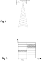
Fig. 1 shows a typical single sector base station; -
Fig.2 shows an example of resource allocation in the frequency-time grid, received from a particular antenna in a cellular network; -
Fig.3 shows an example of an antenna array having sixteen directional antennas; -
Fig. 4 shows an arrangement for determining angle of arrival (AoA) of signals from user equipments in accordance with an embodiment of the present invention; -
Fig. 5 shows an example of an antenna array that supports uplink antenna diversity; -
Fig. 6 shows details of the angle processing unit (APU); -
Fig. 7 shows details of the signal processing steps in angle processing unit (APU); and -
Fig. 8 shows details of the signal processing steps in angle processing unit (APU) for a phased array. - The present invention will be described with respect to a LTE cellular network, however this invention is applicable and can be applied to a variety of cellular networks and thus is not limited to a LTE cellular network.
- A typical cell of a cellular network has a central base station for transmitting and receiving radio frequency (RF) signals within a respective geographic area. As shown in
Fig.1 , a typical base station in a LTE cellular network consists of two transmitting antennas required for multiple-input/multiple-output (MIMO) and two receiving antennas for diversity reception and multi-user MIMO. The base station transmits RF signals to a plurality of user equipments (UEs) via a downlink channel and receives RF signals from a plurality of UEs via an uplink channel within the cell. - The LTE standard supports both FDD (frequency division duplexing) and TDD (time division duplexing) modes. In the time domain, a radio frame has duration of 10 ms and is divided into 20 equally sized slots of 0.5 ms. A sub-frame is defined as two consecutive slots, so one radio frame contains 10 sub-frames. In the frequency domain, one sub-carrier has bandwidth of 15 kHz and a resource block (RB) is defined as consisting of 12 sub-carriers over a slot duration of 0.5 ms, thus one resource block (RB) is 180 kHz. For FDD mode, 10 sub-frames are available for downlink transmission and 10 sub-frames are available for uplink transmission in each 10 ms interval. Uplink and downlink transmissions are separated in the frequency domain. For TDD mode, a sub-frame is either allocated to downlink or uplink transmission. Uplink and downlink transmissions alternate in the time domain using the same frequency bands.
- In the uplink, data is allocated in multiples of one resource block. In FDD applications, the uplink resource block size in the frequency domain contains 12 sub-carriers and the transmission time interval is 1ms long. The uplink resource blocks are assigned to the user equipment (UE) by the base station scheduler that is called evolved Node B (eNB). Since the base station assigns certain time/frequency blocks to the UEs and informs UEs about the transmission format to use, the base station has complete knowledge of which user has used a specific frequency bin at a specific time slot. The UEs may hop from sub-frame to sub-frame.
Figure 2 shows an exemplary diagram of resource allocation in the frequency-time grid, received from a particular antenna in a cellular network. As shown inFig.2 , the UE hops to another frequency allocation from one slot to another within one sub-frame. - In accordance with an embodiment of the present invention, the base station may employ an antenna array having N directional antennas for receiving RF signals from a plurality of user equipments (UEs). Each of the directional antennas can receive signals coming from a specific direction.
Figure 3 shows an example of anantenna array 10 having sixteen directional antennas 12 (in this case, N=16). The angle resolution is approximately 22.5°. An additionaldownlink receiving antenna 14 is mounted on theantenna array 10 for receiving the downlink signals from the base station. -
Figure 4 shows an arrangement for determining the angle of arrival of any signals from user equipments according to an embodiment of the present invention. Theantenna segments 20 to 22 correspond to thedirectional antennas 12 of theantenna array 10 to observe the spatial resolution.Antenna 24 corresponds to the omni-directional antenna 14 of theantenna array 10 to observe the downlink signal. Optional filters and amplifiers that are typically arranged close to each antenna are not shown for simplicity. Thecombiner 30 combines all the received uplink signals fromantenna segments 20 to 22 and sends the combined signal to thebase station 40 as if the signals were received from a single antenna. In order to determine the angle of arrival (AoA) of signals from user equipments (UEs), an angle processing unit (APU) 50 is introduced in the system to process all the received signals and send the AoA information to thebase station 40. - Most base stations support a transmission method using more than one antenna to receive or transmit RF signals along different propagation paths, for example, using antenna diversity or multiple-input/multiple-output (MIMO) antenna scheme. This method can provide better signal quality and increase reliability. In this invention, an example for uplink antenna diversity using two identical antenna arrays is described.
Figure 5 shows an example of an antenna configuration that supports uplink receiving antenna diversity. In order to distinguish the signals coming from one antenna array or from the other, signals received from the first array are denoted as "main" and the signals from the other one are denoted as "auxiliary". -
Figure 6 shows the details of angle processing unit (APU) 50 using antenna diversity for uplink transmission, for example, two receiving antennas per direction are used to receive RF signals. The APU receives two signals from each antenna segment, a main and an auxiliary signal, respectively. A plurality ofsignals monitoring devices 54 receive the uplink signals from each of the antenna segments before being combined together by the combiner (30 inFig. 4 ) and acquire the time slots of the downlink signals sent by the base station and received by the downlink receiving antenna. The task of thesignal monitoring units 54 is to provide the usage of the frequency band from each of the antenna segments. For each of uplink signals, the received signal strength indication (RSSI) value is determined by thesignal monitoring units 54 for given time/frequency blocks. An angle of arrival (AoA)server 52 receives RSSI values of all the antenna segments sent by thesignal monitoring units 54 and determines the angle of arrival (AoA) of signals from user equipments (UEs). The AoA information is then sent to the base station. Since the base station controls the assignment of certain time slot/frequency blocks to the user equipments (UEs), the base station can uniquely identify who of the end users has used a specific frequency bin at a specific time slot. In case the base station is asked to deliver the AoA information, it sends the request to theAPU 50. Then, theAPU 50 acquires RSSI values for all particular time/frequency blocks from all the antennas and determines the AoA from the user equipments. The AoA information is then sent to the base station. An assessment of these RSSI values, e.g., triangulation, provides a good estimation of locations where user equipments are sending RF signals. The distribution of network traffic is then estimated by aggregating the AoA information together with its frequency allocations of the user equipments at the base station. Atiming analyzer 56 unit receives downlink signals from the base station and provides to each of thesignal monitoring units 54. -
Figure 7 shows a detailed block diagram of the signal processing steps in angle processing unit (APU) for uplink antenna diversity. The RF downlink signal is first down-converted to baseband by means of a transceiver (TRX) 62 that contains suitable amplifiers, an oscillator, mixers and appropriate filters. The signal is then digitized by a pair of analog-to-digital (ADC)converters 63. Likewise, the uplink signal received from the main antenna at a specific direction is converted to digital baseband by aTRX 72 andADCs 73. Thetime synchronization 64 of downlink and uplink data is performed by means of standard techniques that are also employed in mobile terminal devices. For a given time slot, the signal fromtime synchronization 64 is used to select 75 a specific window of data samples from the sample streams to be processed by a discrete Fourier transform (DFT) 76. The squared absolute value of each DFT output is computed 68 and the relevant outputs are combined 69 to form an RSSI value for the given time slot/frequency block. Optionally, a second received signal coming from an auxiliary antenna at the same direction can be processed in the same manner. The outputs of this second path are then combined together with the outputs of the main antenna and this combined RSSI value can provide a better AoA estimation. - In an alternative embodiment applicable to TDD (time division duplexing) mode, in which uplink and downlink transmissions alternate in the time domain using the same frequency bands, a switching mechanism can be used to alternate the downlink and the uplink transmissions on the same frequency. However, the downlink time synchronization block must additionally assess the control information about the downlink and uplink periods. In LTE, this control information can be retrieved from one of the control channels from the downlink transmission. An additional signal needs to be generated and conveyed to the uplink signal processing paths to exclude downlink signals from being processed. Alternatively, a signal provided by the base station that is used to control the power amplifier in a TDD system can be used instead.
- In accordance with an another alternative embodiment of the present invention, the base station may use its own antennas for receiving and transmitting RF signals from/to user equipments as shown in
Fig. 1 . An antenna array, as shown inFig. 2 , may be placed in the proximity of the base station for determining the angle of arrival of signals from user equipments and therefore estimating the network traffic. In this case, it is not necessary to route the signals to the base station. - In accordance with still another alternative embodiment of the present invention, the base station may employ an antenna array having omni-directional antennas with beam forming techniques for receiving RF signals from user equipments (UEs). For instance, a phased array can be used for the angle of arrival (AoA) measurements. A phased array can be based on some omni-directional antennas that are placed on some grids. By adding a phase shift to each antenna such that signals coming from a desired direction are reinforced and signals from undesired directions are suppressed, the signal transmission or reception of the antenna array can be directed. Since the necessary phases to form a desired direction are frequency dependent, the phase weighting of different signals is best performed in baseband after DFT processing. For simplicity,
Figure 8 shows the block diagram of the signal processing steps for a phased array using only two antennas with uplink antenna diversity for directive reception. - As shown in
Fig. 8 , the RF downlink signal is first down-converted to baseband by means of a transceiver (TRX) 62 and then digitized by a pair of analog-to-digital (ADC)converters 63. Likewise, the uplink signals received frommain antenna 1 andmain antenna 2 are converted to digital baseband by aTRX 72 andADCs 73. Thetime synchronization 64 of downlink and uplink data is performed by means of standard techniques such as correlation and peak searching that are also employed in mobile terminal devices. For a given time slot, the output signal fromtime synchronization unit 64 is used to select 75 a specific window of data samples from the sample streams to process a discrete Fourier transform (DFT) 76. A phase shift is added to each of data samples using aweight matrix 77 to achieve the desired direction. The squared absolute value of each DFT output is computed 78 and the relevant outputs are combined 79 to form an RSSI value for the given time slot/frequency block. Optionally, the second received signals coming from theauxiliary antenna 1 and theauxiliary antenna 2 are processed in the same manner. The outputs of this second path are then combined together with the outputs of the main antenna and this combined RSSI value can provide a better AoA estimation. - Although the present invention has been described with preferred exemplary embodiments, various changes and modifications may be made by those skilled in the art without departing from the scope of the invention as defined by the appended claims.
Claims (14)
- An arrangement for estimating network traffic based on angle of arrival determination in a cellular network, the arrangement being adapted to carry out the method according to claim 10, in which a cell is served by a base station (40), wherein said base station (40) is adapted to transmit radio frequency signals to a plurality of user equipments via a downlink channel and to receive said radio frequency signals from a plurality of said user equipments via an uplink channel within said cell, the arrangement comprising:a. an antenna array (10) of directional antennas (12, 20, 22), wherein each of said directional antennas (12, 20, 22) is configured to receive uplink signals coming from said user equipments at a specific direction or
a phased array of omnidirectional antennas configured to receive uplink signals coming from said user equipments at specific directions;b. a downlink receiving antenna (14, 24) mounted on said antenna array (10) configured to receive downlink signals from said base station (40);c. a combiner (30) adapted to combine all received said uplink signals from said directional antennas (12, 20, 22) and to send the combined signal to said base station (40); andd. an angle processing unit (50) configured to determine the angle of arrival of said radio frequency signals from said user equipments and communicatively linked to said base station (40). - The arrangement according to claim 1, wherein said angle processing unit (50) includes:a. a plurality of signal monitoring devices (54) adapted to receive each of said uplink signals from said directional antennas (12, 20, 22) and to acquire the time slots of said downlink signals sent by said base station (40) and received by said downlink receiving antenna (14, 24); andb. an angle of arrival server (52) configured to determine the angle of arrival of said radio frequency signals from said user equipments by monitoring the usage of the frequency band and to deliver said angle of arrival information to said base station (40).
- The arrangement according to claim 1 or claim 2, wherein said base station (40) is provided with complete knowledge of the time slot/frequency allocations of said user equipments in the uplink.
- The arrangement according to any one of claims 1 to 3, wherein means for estimating network traffic by aggregating said angle of arrival information together with said time slot/frequency allocations from said user equipments at said base station (40) are arranged.
- The arrangement according to any one of claims 1 to 4, wherein means for modulating said radio frequency signals according to LTE are arranged.
- The arrangement according to any one of claims 1 to 4, wherein means for modulation said radio frequency signals according to GSM are arranged.
- The arrangement according to any one of claims 1 to 6, wherein at least two antenna arrays (10) are arranged for providing said directional antennas (12, 20, 22) with at least two receiving antennas per direction configured to receive said radio frequency signals sent by said user equipments.
- The arrangement according to any one of claims 1 to 7, wherein said directional antennas (12, 20, 22) are adapted to use multiple input/multiple output, MIMO,scheme.
- The arrangement according to claim 1, wherein the phased array of omnidirectional antennas is adapted to use beam forming techniques to achieve directive reception.
- A method for estimating network traffic based on angle of arrival determination in a cellular network in which a cell is served by a base station (40), wherein said base station (40) transmits radio frequency signals to a plurality of user equipments via a downlink channel and receives said radio frequency signals from a plurality of said user equipments via an uplink channel within said cell, characterized bya. selecting a specific time slot from the downlink radio frequency signals received by a downlink receiving antenna (14, 24);b. calculating the received signal strength indication values for each of the resource blocks at said specific time slot from the uplink radio frequency signals received by an antenna array (10) by;i. first applying a discrete Fourier transform to the samples of the selected time slot,ii. calculating the squared absolute value over the discrete Fourier transform output,iii. summing the squared absolute values that belong to one resource block, respectively, and presenting those as received signal strength indication values to the output;c. delivering said received signal strength indication values of all said antennas to an angle of arrival server (52) of an angle processing unit (50); andd. determining the angle of arrival of said radio frequency signals from said user equipments by monitoring said received signal strength indication values.
- The method according to claim 10, further comprising:providing at least two antenna arrays (10) to provide at least two receiving antennas per direction to receive said radio frequency signals sent by said user equipments, wherein said received signal strength indication values of at least two said receiving antennas are calculated individually and then combined together.
- The method according to claim 10 or claim 11, further comprising: retrieving control information from one of the control channels of said downlink signals in time division duplexing mode, wherein said control information is assessed to additionally identify downlink and uplink transmission intervals.
- The method according to claim 10 or 11, further comprising: providing a downlink/uplink switching signal by said base station (40), wherein said downlink/uplink switching signal is sent to said angle processing unit (50) to exclude downlink information.
- The method according to any one of claims 10 to 13, further comprising: adding a weight matrix after processing the discrete Fourier transform to form a desired phase shift.
Priority Applications (2)
| Application Number | Priority Date | Filing Date | Title |
|---|---|---|---|
| EP10165292.3A EP2282574B1 (en) | 2009-08-07 | 2010-06-08 | Arrangement and method for estimating network traffic based on angle of arrival determination in a cellular network |
| PCT/EP2010/061606 WO2011015671A1 (en) | 2009-08-07 | 2010-08-10 | Arrangement and method for estimating network traffic based on angle of arrival determination in a cellular network |
Applications Claiming Priority (2)
| Application Number | Priority Date | Filing Date | Title |
|---|---|---|---|
| EP09167508 | 2009-08-07 | ||
| EP10165292.3A EP2282574B1 (en) | 2009-08-07 | 2010-06-08 | Arrangement and method for estimating network traffic based on angle of arrival determination in a cellular network |
Publications (3)
| Publication Number | Publication Date |
|---|---|
| EP2282574A2 EP2282574A2 (en) | 2011-02-09 |
| EP2282574A3 EP2282574A3 (en) | 2011-04-06 |
| EP2282574B1 true EP2282574B1 (en) | 2017-08-09 |
Family
ID=41278582
Family Applications (1)
| Application Number | Title | Priority Date | Filing Date |
|---|---|---|---|
| EP10165292.3A Active EP2282574B1 (en) | 2009-08-07 | 2010-06-08 | Arrangement and method for estimating network traffic based on angle of arrival determination in a cellular network |
Country Status (2)
| Country | Link |
|---|---|
| EP (1) | EP2282574B1 (en) |
| WO (2) | WO2011017700A1 (en) |
Families Citing this family (27)
| Publication number | Priority date | Publication date | Assignee | Title |
|---|---|---|---|---|
| US11451275B2 (en) | 2004-04-02 | 2022-09-20 | Rearden, Llc | System and method for distributed antenna wireless communications |
| US20100054746A1 (en) | 2007-07-24 | 2010-03-04 | Eric Raymond Logan | Multi-port accumulator for radio-over-fiber (RoF) wireless picocellular systems |
| US8175459B2 (en) | 2007-10-12 | 2012-05-08 | Corning Cable Systems Llc | Hybrid wireless/wired RoF transponder and hybrid RoF communication system using same |
| US8644844B2 (en) | 2007-12-20 | 2014-02-04 | Corning Mobileaccess Ltd. | Extending outdoor location based services and applications into enclosed areas |
| US9673904B2 (en) | 2009-02-03 | 2017-06-06 | Corning Optical Communications LLC | Optical fiber-based distributed antenna systems, components, and related methods for calibration thereof |
| WO2010091004A1 (en) | 2009-02-03 | 2010-08-12 | Corning Cable Systems Llc | Optical fiber-based distributed antenna systems, components, and related methods for calibration thereof |
| US9590733B2 (en) | 2009-07-24 | 2017-03-07 | Corning Optical Communications LLC | Location tracking using fiber optic array cables and related systems and methods |
| CN102845001B (en) | 2010-03-31 | 2016-07-06 | 康宁光缆系统有限责任公司 | Based on positioning service in the distributed communication assembly of optical fiber and system and associated method |
| US8570914B2 (en) | 2010-08-09 | 2013-10-29 | Corning Cable Systems Llc | Apparatuses, systems, and methods for determining location of a mobile device(s) in a distributed antenna system(s) |
| US9252874B2 (en) | 2010-10-13 | 2016-02-02 | Ccs Technology, Inc | Power management for remote antenna units in distributed antenna systems |
| WO2012148938A1 (en) | 2011-04-29 | 2012-11-01 | Corning Cable Systems Llc | Determining propagation delay of communications in distributed antenna systems, and related components, systems and methods |
| US9781553B2 (en) | 2012-04-24 | 2017-10-03 | Corning Optical Communications LLC | Location based services in a distributed communication system, and related components and methods |
| WO2013181247A1 (en) | 2012-05-29 | 2013-12-05 | Corning Cable Systems Llc | Ultrasound-based localization of client devices with inertial navigation supplement in distributed communication systems and related devices and methods |
| US9158864B2 (en) | 2012-12-21 | 2015-10-13 | Corning Optical Communications Wireless Ltd | Systems, methods, and devices for documenting a location of installed equipment |
| US10164698B2 (en) | 2013-03-12 | 2018-12-25 | Rearden, Llc | Systems and methods for exploiting inter-cell multiplexing gain in wireless cellular systems via distributed input distributed output technology |
| RU2767777C2 (en) * | 2013-03-15 | 2022-03-21 | Риарден, Ллк | Systems and methods of radio frequency calibration using the principle of reciprocity of channels in wireless communication with distributed input - distributed output |
| TWI511473B (en) | 2013-07-01 | 2015-12-01 | Ind Tech Res Inst | Electronic device and data control method |
| US9077321B2 (en) | 2013-10-23 | 2015-07-07 | Corning Optical Communications Wireless Ltd. | Variable amplitude signal generators for generating a sinusoidal signal having limited direct current (DC) offset variation, and related devices, systems, and methods |
| WO2015145217A1 (en) | 2014-03-28 | 2015-10-01 | Telefonaktiebolaget L M Ericsson (Publ) | Observed time difference of arrival angle of arrival discriminator |
| CN106851550B (en) * | 2015-12-04 | 2020-02-14 | 华为技术有限公司 | Method for positioning terminal and baseband unit |
| US9648580B1 (en) | 2016-03-23 | 2017-05-09 | Corning Optical Communications Wireless Ltd | Identifying remote units in a wireless distribution system (WDS) based on assigned unique temporal delay patterns |
| JP7020545B2 (en) | 2017-10-04 | 2022-02-16 | 日本電気株式会社 | Remote radio head, beamforming method and program |
| US10659099B1 (en) * | 2018-12-12 | 2020-05-19 | Samsung Electronics Co., Ltd. | Page scanning devices, computer-readable media, and methods for bluetooth page scanning using a wideband receiver |
| CN109829525B (en) * | 2019-01-24 | 2020-04-07 | 清华大学 | Building control method and system based on swarm intelligence |
| CN112910514B (en) * | 2019-12-04 | 2022-04-01 | 中国移动通信集团设计院有限公司 | Parameter configuration method and device of MIMO (multiple input multiple output) antenna |
| US11528063B2 (en) | 2020-11-25 | 2022-12-13 | Corning Incorporated | Supporting distributed massive multiple-input multiple-output (DM-MIMO) in a distributed communications system (DCS) |
| CN113115205B (en) * | 2021-03-31 | 2022-05-17 | 北京理工大学 | Distributed cooperative positioning method based on angle measurement |
Family Cites Families (13)
| Publication number | Priority date | Publication date | Assignee | Title |
|---|---|---|---|---|
| US6999438B2 (en) * | 1996-01-18 | 2006-02-14 | Kabushiki Kaisha Toshiba | Radio communication system |
| US5859838A (en) * | 1996-07-30 | 1999-01-12 | Qualcomm Incorporated | Load monitoring and management in a CDMA wireless communication system |
| DE69837389T2 (en) * | 1997-08-18 | 2007-12-20 | Telefonaktiebolaget Lm Ericsson (Publ) | METHOD AND SYSTEM FOR THE POSITION DETERMINATION OF MOBILE RADIO TERMINALS |
| GB2335570A (en) * | 1998-03-21 | 1999-09-22 | Siemens Ag | Traffic distribution measurement in a mobile radio network |
| US6873290B2 (en) * | 1999-01-08 | 2005-03-29 | Trueposition, Inc. | Multiple pass location processor |
| US6397066B1 (en) * | 1999-10-29 | 2002-05-28 | Verizon Laboratories Inc. | Fast method for capacity estimation of systems |
| US7043273B2 (en) * | 2002-01-15 | 2006-05-09 | Telefonaktiebolaget Lm Ericsson (Publ) | Diversity branch delay alignment in radio base station |
| JP4022625B2 (en) * | 2004-03-08 | 2007-12-19 | 独立行政法人情報通信研究機構 | Communication system, communication method, base station, and mobile station |
| JP4562542B2 (en) * | 2005-02-15 | 2010-10-13 | 三洋電機株式会社 | CALIBRATION METHOD AND BASE STATION DEVICE, TERMINAL DEVICE, AND RADIO DEVICE USING THE SAME |
| JP4732239B2 (en) * | 2006-05-29 | 2011-07-27 | 京セラ株式会社 | Radio base station and radio base station control method |
| US8140092B2 (en) * | 2007-04-18 | 2012-03-20 | Trueposition, Inc. | Sparsed U-TDOA wireless location networks |
| US8548488B2 (en) * | 2007-11-30 | 2013-10-01 | Trueposition, Inc. | Automated configuration of a wireless location system |
| US9066308B2 (en) * | 2007-12-04 | 2015-06-23 | Qualcomm Incorporated | Method and apparatus for using supported network information for positioning |
-
2010
- 2010-06-08 EP EP10165292.3A patent/EP2282574B1/en active Active
- 2010-08-09 WO PCT/US2010/044884 patent/WO2011017700A1/en active Application Filing
- 2010-08-10 WO PCT/EP2010/061606 patent/WO2011015671A1/en active Application Filing
Non-Patent Citations (1)
| Title |
|---|
| None * |
Also Published As
| Publication number | Publication date |
|---|---|
| WO2011015671A1 (en) | 2011-02-10 |
| WO2011017700A1 (en) | 2011-02-10 |
| WO2011015671A8 (en) | 2012-04-19 |
| EP2282574A3 (en) | 2011-04-06 |
| EP2282574A2 (en) | 2011-02-09 |
Similar Documents
| Publication | Publication Date | Title |
|---|---|---|
| EP2282574B1 (en) | Arrangement and method for estimating network traffic based on angle of arrival determination in a cellular network | |
| US9867192B2 (en) | System and method for beam selection using multiple frequencies | |
| EP2749080B1 (en) | A method and a central base station for interference management in a cellular network | |
| CN107210811B (en) | Method for distributed massive MIMO (DM-MIMO) | |
| JP6386472B2 (en) | Method and apparatus for uplink power control in a wireless communication system based on beamforming | |
| JP6053305B2 (en) | Wireless base station, wireless communication system, and wireless communication method | |
| CN101594620B (en) | Method of and base station for controlling beam forming in a mobile cellular network | |
| CN110546929A (en) | Channel state information reference signal (CSI-RS) for layer 3(L3) mobility | |
| TW201743580A (en) | Methods and appratus to support mobility | |
| US20180262933A1 (en) | Evaluating performance of remote units on a per remote unit basis in a distributed antenna system (das) | |
| CN108667496B (en) | Method and device for acquiring and feeding back transmission beam information | |
| US20180205443A1 (en) | Wireless base station and terminal, and system and method for wireless communication | |
| US10833736B2 (en) | Hybrid beamforming method for beam-based cooperative transmission, and apparatus for the same | |
| US20140293803A1 (en) | Coordinated Multi-Point Transmission and Multi-User MIMO | |
| CN110999175A (en) | Wireless communication method | |
| US20080165741A1 (en) | Methods for interference measurement and prediction | |
| EP3298708B1 (en) | Validation sub-system for telecommunication system | |
| EP2862289B1 (en) | System and method of wireless fixed access using a multiple antenna array | |
| KR102449735B1 (en) | Method and apparatus for transmitting pilot in multi-antenna communication system, and method and apparatus for allocating pilot in multi-antenna communication system | |
| US20190109661A1 (en) | Interference Mitigation in Radio Frequencies Communication Systems | |
| EP2592764A1 (en) | Method for optimizing radio link transmission in a radio communication system, transmission unit, selection unit, network node, and apparatus thereof |
Legal Events
| Date | Code | Title | Description |
|---|---|---|---|
| PUAI | Public reference made under article 153(3) epc to a published international application that has entered the european phase |
Free format text: ORIGINAL CODE: 0009012 |
|
| AK | Designated contracting states |
Kind code of ref document: A2 Designated state(s): AL AT BE BG CH CY CZ DE DK EE ES FI FR GB GR HR HU IE IS IT LI LT LU LV MC MK MT NL NO PL PT RO SE SI SK SM TR |
|
| AX | Request for extension of the european patent |
Extension state: BA ME RS |
|
| PUAL | Search report despatched |
Free format text: ORIGINAL CODE: 0009013 |
|
| AK | Designated contracting states |
Kind code of ref document: A3 Designated state(s): AL AT BE BG CH CY CZ DE DK EE ES FI FR GB GR HR HU IE IS IT LI LT LU LV MC MK MT NL NO PL PT RO SE SI SK SM TR |
|
| AX | Request for extension of the european patent |
Extension state: BA ME RS |
|
| 17P | Request for examination filed |
Effective date: 20111006 |
|
| 17Q | First examination report despatched |
Effective date: 20130404 |
|
| RAP1 | Party data changed (applicant data changed or rights of an application transferred) |
Owner name: INTEL MOBILE COMMUNICATIONS GMBH |
|
| RAP1 | Party data changed (applicant data changed or rights of an application transferred) |
Owner name: INTEL DEUTSCHLAND GMBH |
|
| GRAP | Despatch of communication of intention to grant a patent |
Free format text: ORIGINAL CODE: EPIDOSNIGR1 |
|
| RIC1 | Information provided on ipc code assigned before grant |
Ipc: H04W 24/08 20090101AFI20170118BHEP Ipc: H04W 16/28 20090101ALN20170118BHEP Ipc: H04W 16/18 20090101ALN20170118BHEP |
|
| RIC1 | Information provided on ipc code assigned before grant |
Ipc: H04W 24/08 20090101AFI20170125BHEP Ipc: H04W 16/18 20090101ALN20170125BHEP Ipc: H04W 16/28 20090101ALN20170125BHEP |
|
| INTG | Intention to grant announced |
Effective date: 20170213 |
|
| GRAS | Grant fee paid |
Free format text: ORIGINAL CODE: EPIDOSNIGR3 |
|
| GRAA | (expected) grant |
Free format text: ORIGINAL CODE: 0009210 |
|
| AK | Designated contracting states |
Kind code of ref document: B1 Designated state(s): AL AT BE BG CH CY CZ DE DK EE ES FI FR GB GR HR HU IE IS IT LI LT LU LV MC MK MT NL NO PL PT RO SE SI SK SM TR |
|
| REG | Reference to a national code |
Ref country code: GB Ref legal event code: FG4D |
|
| REG | Reference to a national code |
Ref country code: CH Ref legal event code: EP Ref country code: AT Ref legal event code: REF Ref document number: 918052 Country of ref document: AT Kind code of ref document: T Effective date: 20170815 |
|
| REG | Reference to a national code |
Ref country code: IE Ref legal event code: FG4D |
|
| REG | Reference to a national code |
Ref country code: DE Ref legal event code: R096 Ref document number: 602010044203 Country of ref document: DE |
|
| REG | Reference to a national code |
Ref country code: NL Ref legal event code: MP Effective date: 20170809 |
|
| REG | Reference to a national code |
Ref country code: LT Ref legal event code: MG4D |
|
| REG | Reference to a national code |
Ref country code: AT Ref legal event code: MK05 Ref document number: 918052 Country of ref document: AT Kind code of ref document: T Effective date: 20170809 |
|
| PG25 | Lapsed in a contracting state [announced via postgrant information from national office to epo] |
Ref country code: AT Free format text: LAPSE BECAUSE OF FAILURE TO SUBMIT A TRANSLATION OF THE DESCRIPTION OR TO PAY THE FEE WITHIN THE PRESCRIBED TIME-LIMIT Effective date: 20170809 Ref country code: NO Free format text: LAPSE BECAUSE OF FAILURE TO SUBMIT A TRANSLATION OF THE DESCRIPTION OR TO PAY THE FEE WITHIN THE PRESCRIBED TIME-LIMIT Effective date: 20171109 Ref country code: FI Free format text: LAPSE BECAUSE OF FAILURE TO SUBMIT A TRANSLATION OF THE DESCRIPTION OR TO PAY THE FEE WITHIN THE PRESCRIBED TIME-LIMIT Effective date: 20170809 Ref country code: LT Free format text: LAPSE BECAUSE OF FAILURE TO SUBMIT A TRANSLATION OF THE DESCRIPTION OR TO PAY THE FEE WITHIN THE PRESCRIBED TIME-LIMIT Effective date: 20170809 Ref country code: NL Free format text: LAPSE BECAUSE OF FAILURE TO SUBMIT A TRANSLATION OF THE DESCRIPTION OR TO PAY THE FEE WITHIN THE PRESCRIBED TIME-LIMIT Effective date: 20170809 Ref country code: SE Free format text: LAPSE BECAUSE OF FAILURE TO SUBMIT A TRANSLATION OF THE DESCRIPTION OR TO PAY THE FEE WITHIN THE PRESCRIBED TIME-LIMIT Effective date: 20170809 Ref country code: HR Free format text: LAPSE BECAUSE OF FAILURE TO SUBMIT A TRANSLATION OF THE DESCRIPTION OR TO PAY THE FEE WITHIN THE PRESCRIBED TIME-LIMIT Effective date: 20170809 |
|
| PG25 | Lapsed in a contracting state [announced via postgrant information from national office to epo] |
Ref country code: LV Free format text: LAPSE BECAUSE OF FAILURE TO SUBMIT A TRANSLATION OF THE DESCRIPTION OR TO PAY THE FEE WITHIN THE PRESCRIBED TIME-LIMIT Effective date: 20170809 Ref country code: GR Free format text: LAPSE BECAUSE OF FAILURE TO SUBMIT A TRANSLATION OF THE DESCRIPTION OR TO PAY THE FEE WITHIN THE PRESCRIBED TIME-LIMIT Effective date: 20171110 Ref country code: PL Free format text: LAPSE BECAUSE OF FAILURE TO SUBMIT A TRANSLATION OF THE DESCRIPTION OR TO PAY THE FEE WITHIN THE PRESCRIBED TIME-LIMIT Effective date: 20170809 Ref country code: IS Free format text: LAPSE BECAUSE OF FAILURE TO SUBMIT A TRANSLATION OF THE DESCRIPTION OR TO PAY THE FEE WITHIN THE PRESCRIBED TIME-LIMIT Effective date: 20171209 Ref country code: BG Free format text: LAPSE BECAUSE OF FAILURE TO SUBMIT A TRANSLATION OF THE DESCRIPTION OR TO PAY THE FEE WITHIN THE PRESCRIBED TIME-LIMIT Effective date: 20171109 Ref country code: ES Free format text: LAPSE BECAUSE OF FAILURE TO SUBMIT A TRANSLATION OF THE DESCRIPTION OR TO PAY THE FEE WITHIN THE PRESCRIBED TIME-LIMIT Effective date: 20170809 |
|
| PG25 | Lapsed in a contracting state [announced via postgrant information from national office to epo] |
Ref country code: RO Free format text: LAPSE BECAUSE OF FAILURE TO SUBMIT A TRANSLATION OF THE DESCRIPTION OR TO PAY THE FEE WITHIN THE PRESCRIBED TIME-LIMIT Effective date: 20170809 Ref country code: CZ Free format text: LAPSE BECAUSE OF FAILURE TO SUBMIT A TRANSLATION OF THE DESCRIPTION OR TO PAY THE FEE WITHIN THE PRESCRIBED TIME-LIMIT Effective date: 20170809 Ref country code: DK Free format text: LAPSE BECAUSE OF FAILURE TO SUBMIT A TRANSLATION OF THE DESCRIPTION OR TO PAY THE FEE WITHIN THE PRESCRIBED TIME-LIMIT Effective date: 20170809 |
|
| REG | Reference to a national code |
Ref country code: DE Ref legal event code: R097 Ref document number: 602010044203 Country of ref document: DE |
|
| PG25 | Lapsed in a contracting state [announced via postgrant information from national office to epo] |
Ref country code: EE Free format text: LAPSE BECAUSE OF FAILURE TO SUBMIT A TRANSLATION OF THE DESCRIPTION OR TO PAY THE FEE WITHIN THE PRESCRIBED TIME-LIMIT Effective date: 20170809 Ref country code: SK Free format text: LAPSE BECAUSE OF FAILURE TO SUBMIT A TRANSLATION OF THE DESCRIPTION OR TO PAY THE FEE WITHIN THE PRESCRIBED TIME-LIMIT Effective date: 20170809 Ref country code: SM Free format text: LAPSE BECAUSE OF FAILURE TO SUBMIT A TRANSLATION OF THE DESCRIPTION OR TO PAY THE FEE WITHIN THE PRESCRIBED TIME-LIMIT Effective date: 20170809 Ref country code: IT Free format text: LAPSE BECAUSE OF FAILURE TO SUBMIT A TRANSLATION OF THE DESCRIPTION OR TO PAY THE FEE WITHIN THE PRESCRIBED TIME-LIMIT Effective date: 20170809 |
|
| PLBE | No opposition filed within time limit |
Free format text: ORIGINAL CODE: 0009261 |
|
| STAA | Information on the status of an ep patent application or granted ep patent |
Free format text: STATUS: NO OPPOSITION FILED WITHIN TIME LIMIT |
|
| 26N | No opposition filed |
Effective date: 20180511 |
|
| PG25 | Lapsed in a contracting state [announced via postgrant information from national office to epo] |
Ref country code: SI Free format text: LAPSE BECAUSE OF FAILURE TO SUBMIT A TRANSLATION OF THE DESCRIPTION OR TO PAY THE FEE WITHIN THE PRESCRIBED TIME-LIMIT Effective date: 20170809 |
|
| REG | Reference to a national code |
Ref country code: CH Ref legal event code: PL |
|
| GBPC | Gb: european patent ceased through non-payment of renewal fee |
Effective date: 20180608 |
|
| REG | Reference to a national code |
Ref country code: BE Ref legal event code: MM Effective date: 20180630 |
|
| REG | Reference to a national code |
Ref country code: IE Ref legal event code: MM4A |
|
| PG25 | Lapsed in a contracting state [announced via postgrant information from national office to epo] |
Ref country code: LU Free format text: LAPSE BECAUSE OF NON-PAYMENT OF DUE FEES Effective date: 20180608 Ref country code: MC Free format text: LAPSE BECAUSE OF FAILURE TO SUBMIT A TRANSLATION OF THE DESCRIPTION OR TO PAY THE FEE WITHIN THE PRESCRIBED TIME-LIMIT Effective date: 20170809 |
|
| PG25 | Lapsed in a contracting state [announced via postgrant information from national office to epo] |
Ref country code: LI Free format text: LAPSE BECAUSE OF NON-PAYMENT OF DUE FEES Effective date: 20180630 Ref country code: CH Free format text: LAPSE BECAUSE OF NON-PAYMENT OF DUE FEES Effective date: 20180630 Ref country code: GB Free format text: LAPSE BECAUSE OF NON-PAYMENT OF DUE FEES Effective date: 20180608 Ref country code: FR Free format text: LAPSE BECAUSE OF NON-PAYMENT OF DUE FEES Effective date: 20180630 Ref country code: IE Free format text: LAPSE BECAUSE OF NON-PAYMENT OF DUE FEES Effective date: 20180608 |
|
| PG25 | Lapsed in a contracting state [announced via postgrant information from national office to epo] |
Ref country code: BE Free format text: LAPSE BECAUSE OF NON-PAYMENT OF DUE FEES Effective date: 20180630 |
|
| PG25 | Lapsed in a contracting state [announced via postgrant information from national office to epo] |
Ref country code: MT Free format text: LAPSE BECAUSE OF NON-PAYMENT OF DUE FEES Effective date: 20180608 |
|
| PG25 | Lapsed in a contracting state [announced via postgrant information from national office to epo] |
Ref country code: TR Free format text: LAPSE BECAUSE OF FAILURE TO SUBMIT A TRANSLATION OF THE DESCRIPTION OR TO PAY THE FEE WITHIN THE PRESCRIBED TIME-LIMIT Effective date: 20170809 |
|
| PG25 | Lapsed in a contracting state [announced via postgrant information from national office to epo] |
Ref country code: PT Free format text: LAPSE BECAUSE OF FAILURE TO SUBMIT A TRANSLATION OF THE DESCRIPTION OR TO PAY THE FEE WITHIN THE PRESCRIBED TIME-LIMIT Effective date: 20170809 Ref country code: HU Free format text: LAPSE BECAUSE OF FAILURE TO SUBMIT A TRANSLATION OF THE DESCRIPTION OR TO PAY THE FEE WITHIN THE PRESCRIBED TIME-LIMIT; INVALID AB INITIO Effective date: 20100608 |
|
| PG25 | Lapsed in a contracting state [announced via postgrant information from national office to epo] |
Ref country code: CY Free format text: LAPSE BECAUSE OF FAILURE TO SUBMIT A TRANSLATION OF THE DESCRIPTION OR TO PAY THE FEE WITHIN THE PRESCRIBED TIME-LIMIT Effective date: 20170809 Ref country code: MK Free format text: LAPSE BECAUSE OF NON-PAYMENT OF DUE FEES Effective date: 20170809 |
|
| PG25 | Lapsed in a contracting state [announced via postgrant information from national office to epo] |
Ref country code: AL Free format text: LAPSE BECAUSE OF FAILURE TO SUBMIT A TRANSLATION OF THE DESCRIPTION OR TO PAY THE FEE WITHIN THE PRESCRIBED TIME-LIMIT Effective date: 20170809 |
|
| P01 | Opt-out of the competence of the unified patent court (upc) registered |
Effective date: 20230518 |
|
| PGFP | Annual fee paid to national office [announced via postgrant information from national office to epo] |
Ref country code: DE Payment date: 20230516 Year of fee payment: 14 |