EP1912450A2 - Cellular network based on relay station and space division duplex communication method - Google Patents
Cellular network based on relay station and space division duplex communication method Download PDFInfo
- Publication number
- EP1912450A2 EP1912450A2 EP07013626A EP07013626A EP1912450A2 EP 1912450 A2 EP1912450 A2 EP 1912450A2 EP 07013626 A EP07013626 A EP 07013626A EP 07013626 A EP07013626 A EP 07013626A EP 1912450 A2 EP1912450 A2 EP 1912450A2
- Authority
- EP
- European Patent Office
- Prior art keywords
- signal
- base station
- user equipment
- relay station
- downlink
- Prior art date
- Legal status (The legal status is an assumption and is not a legal conclusion. Google has not performed a legal analysis and makes no representation as to the accuracy of the status listed.)
- Granted
Links
Images


Classifications
-
- H—ELECTRICITY
- H04—ELECTRIC COMMUNICATION TECHNIQUE
- H04B—TRANSMISSION
- H04B7/00—Radio transmission systems, i.e. using radiation field
- H04B7/14—Relay systems
- H04B7/15—Active relay systems
- H04B7/155—Ground-based stations
- H04B7/15528—Control of operation parameters of a relay station to exploit the physical medium
- H04B7/15542—Selecting at relay station its transmit and receive resources
-
- H—ELECTRICITY
- H04—ELECTRIC COMMUNICATION TECHNIQUE
- H04W—WIRELESS COMMUNICATION NETWORKS
- H04W72/00—Local resource management
- H04W72/20—Control channels or signalling for resource management
-
- H—ELECTRICITY
- H04—ELECTRIC COMMUNICATION TECHNIQUE
- H04B—TRANSMISSION
- H04B7/00—Radio transmission systems, i.e. using radiation field
- H04B7/24—Radio transmission systems, i.e. using radiation field for communication between two or more posts
- H04B7/26—Radio transmission systems, i.e. using radiation field for communication between two or more posts at least one of which is mobile
- H04B7/2603—Arrangements for wireless physical layer control
- H04B7/2606—Arrangements for base station coverage control, e.g. by using relays in tunnels
-
- H—ELECTRICITY
- H04—ELECTRIC COMMUNICATION TECHNIQUE
- H04W—WIRELESS COMMUNICATION NETWORKS
- H04W16/00—Network planning, e.g. coverage or traffic planning tools; Network deployment, e.g. resource partitioning or cells structures
- H04W16/24—Cell structures
- H04W16/26—Cell enhancers or enhancement, e.g. for tunnels, building shadow
-
- H—ELECTRICITY
- H04—ELECTRIC COMMUNICATION TECHNIQUE
- H04W—WIRELESS COMMUNICATION NETWORKS
- H04W76/00—Connection management
- H04W76/20—Manipulation of established connections
-
- H—ELECTRICITY
- H04—ELECTRIC COMMUNICATION TECHNIQUE
- H04W—WIRELESS COMMUNICATION NETWORKS
- H04W84/00—Network topologies
- H04W84/02—Hierarchically pre-organised networks, e.g. paging networks, cellular networks, WLAN [Wireless Local Area Network] or WLL [Wireless Local Loop]
- H04W84/04—Large scale networks; Deep hierarchical networks
- H04W84/042—Public Land Mobile systems, e.g. cellular systems
- H04W84/047—Public Land Mobile systems, e.g. cellular systems using dedicated repeater stations
Landscapes
- Engineering & Computer Science (AREA)
- Computer Networks & Wireless Communication (AREA)
- Signal Processing (AREA)
- Mobile Radio Communication Systems (AREA)
Abstract
Description
- The present invention relates to a wireless communication technology, especially to a cellular network based on relay station and a space division duplex communication method.
- A future cellular network has characteristics of high data transmission rate and large covering area. According to requirements specified in ITU-R M1645, the data rate is required to reach 1Gbps for a user moving in low speed or being in stationary status, and 100Mbps for a user moving in high speed.
- Generally when a power of a transmitter remains constant, energy of each bit is in inverse ratio with the data rate, i.e. with an increase of data rate, the SNR Eb/No will decrease linearly, which can result in a failure reception of the receiver and therefore a covering area is reduced.
- Furthermore, a working band of Third Generation Wireless Communication (3G) is 2GHz. However, the working band available for Next Generation Network (NGN) is higher than that of 3G, for example 5GHz. The high working band results in more path loss and is more sensitive to fading, which deteriorate the performance of the covering area.
- A relay station (RS) is one of effective methods to solve the above problem. A principle of the RS is to sacrifice capacity for covering area. Because of the limit of resource orthogonality, the RS cannot transmit and receive different signals on the same frequency and code channel at the same time. That is, the transmitting and receiving of the RS must be orthogonal, using different time and frequency. Furthermore, because of the near-far effect, the RS cannot transmit and receive different signals on different code channels at the same time.
- The following is a basic principle of the work of a RS with reference to the downlink of the time division duplex.
- In a traditional cellular network, a base station (BS) and a user equipment (UE) can always use a slot resource allocated to the UE to transmit/receive signals. However, in a cellular network based on RS, the slot resource allocated to the UE can be divided into two parts, one for transmission from a BS to a RS and the other for transmission from the RS to a UE. Thus when a transmitting power is constant, a throughput of the cellular network based on RS is half of that of the traditional network. The above is an explanation of sacrificing capacity for covering area by using RS. The network based on RS can expand the covering area and when transmission distances are the same, it equals to reducing power loss.
- In addition, the RS has advantages of low cost and easy rollout. Besides a base station equipment, a power source and a machine room, the establishment of a base station needs a fiber network that costs a lot. In contrast, the equipment of the RS is simpler than that of the base station and the RS connects with the base station through a wireless link without the need of a fiber network, which reduces the cost of network expansion.
- Channel multiplexing is one important way to improve the use efficiency of each channel and the system capacity. As viewed from the system level, a channel can be multiplexed between different multi-hop users or between a multi-hop user and a one-hop user; as viewed from the link level, a channel can be multiplexed between the uplink and the downlink of one multi-hop user.
- Fig. 1 is a diagram showing a principle of a first communication method in a cellular network based on RS in prior art. As shown in Fig. 1, an uplink (UL) and a downlink (DL) need to occupy independent resources. For a two-hop user, taking time division duplex as an example, all together 4 independent slots are needed and for uplink (UL1, UL2) and downlink (DL1, DL2) respectively. In this case, as shown in Fig. 2, the use efficiency of each channel is only 1 link/slot, which is very low.
- In order to improve the use efficiency of each channel, an improved duplex method is proposed, as shown in Fig. 3. Fig. 3 is a diagram showing a principle of a second communication method in a cellular network based on RS in prior art.
- In the first slot, a signal Xd is transmitted on downlink DL1 from a base station to a RS;
- In the second slot, a signal Xu is transmitted on
uplink UL 1 from a UE to the RS, and after the RS receives and decodes the downlink signal Xd and the uplink signal Xu, it combines the uplink and downlink signals to one signal Xc by a XOR operation; - In the third slot, the RS transmits the combined signal Xc to the base station and the UE through the uplink UL2 and the downlink DL2 respectively and the base station and the UE can receive the signal Xc at the same time. After receiving and decodes the signal Xc, the base station performs the XOR operation on the signal Xc and the signal Xd transmitted in the first slot by the base station and gets the signal Xu, which is transmitted to the base station from the UE. The UE performs the same operation, i.e. it performs the XOR operation on the signal Xu transmitted in the second slot by the UE and the signal Xc received in the third slot by the UE and gets the signal Xd from the base station.
- As shown in Fig. 4, after the above processing, four links (DL1, UL1, DL2 and UL2) can be transmitted in three slots and the use efficiency of each channel is 4 links/3 slots. Compared with the prior art in Fig. 1, the one in Fig. 4 can improve the use efficiency of each channel effectively and thus improve the network performance.
- However, applications in a space domain are not mentioned in the second communication method and when applied in the space domain, the second method is not the optimal solution in improving the use efficiency of each channel.
- An object of the present invention is to provide a cellular network based on relay station (RS).
- Another object of the present invention is to provide a space division duplex communication method.
- According to a first aspect of the present invention, a cellular network based on RS is provided, including a base station, a relay station and a user equipment, wherein the base station has at least one antenna and the relay station has at least two antennas. The base station allocates resources for the user equipment, transmits a downlink signal in a current slot and receives an uplink signal from the user equipment through the relay station in the next slot. The relay station receives the downlink signal from the base station and the uplink signal from the user equipment in the current slot and transmits the received downlink signal to the user equipment and the uplink signal to the base station in the next slot. The user equipment transmits the uplink signal in the current slot and receives the downlink signal through the relay station in the next slot, wherein the uplink signal and the downlink signal transmitted in the same slot are orthogonal.
- According to a second aspect of the present invention, a space division duplex communication method is provided and includes the following steps:
- step a, at a base station, transmitting a broadcasting signal and allocating resources for a user equipment according to a feedback signal corresponding to the broadcasting signal;
- step b, transmitting a downlink signal from the base station and an uplink signal from the user equipment to a relay station in a current slot;
- step c, at the relay station, transmitting the downlink signal received from the base station to the user equipment and the uplink signal received from the user equipment to the base station in the next slot,
- According to a third aspect of the present invention, a cellular network based on RS is provided, including a base station, a first relay station, a second relay station and a user equipment, wherein the base station has at least one antenna and each relay station has at least two antennas. The base station allocates resources for the user equipment, transmits a downlink signal in a current slot and receives an uplink signal from the first relay station in the next slot. The first relay station receives the downlink signal from the base station and the uplink signal from the second relay station in the current slot and transmits the downlink signal to the second relay station and the uplink signal to the base station in the next slot. The second relay station transmits the uplink signal to the first relay station and the downlink signal to the user equipment in the current slot and transmits the received downlink signal to the user equipment and the received uplink signal to the first relay station in the next slot. The user equipment receives the downlink signal from the second relay station in the current slot and transmits the uplink signal in the next slot, wherein the uplink signal and the downlink signal transmitted in the same slot are orthogonal.
- According to a second aspect of the present invention, a space division duplex communication method is provided and includes the following steps:
- step A, at a base station, transmitting a broadcasting signal and allocating resources for a user equipment according to a feedback signal corresponding to the broadcasting signal;
- step B, transmitting a downlink signal from the base station to a first relay station, and at the same time, transmitting from a second relay station an uplink signal to the first relay station and a downlink signal to a user equipment;
- step C, at the first relay station, transmitting the downlink signal received from the base station to the second relay station and the uplink signal received from the second relay station to the base station in the current slot to the base station in the next slot, and at the same time, transmitting the uplink signal from the user equipment to the second relay station,
- According to a fifth aspect of the present invention, a cellular network based on RS is provided, including a base station, a plurality of relay stations and a user equipment, wherein the base station has at least one antenna and each relay station has at least two antennas. At least one relay station among the plurality of relay stations receives a downlink signal from the base station or from the other relay stations and an uplink signal from the user equipment or from the other relay stations in the current slot, and transmits the received downlink signal to the other relay stations or to the user equipment and the received uplink signal to the other relay stations or to the base station in the next slot. And at least one relay station among the plurality of relay stations transmits the downlink signal to the other relay stations or to the user equipment and the uplink signal to the other relay stations or to the base station in the current slot, and receives the downlink signal from the base station or from the other relay stations and the uplink signal from the user equipment or from the other relay stations in the next slot, wherein the uplink signal and the downlink signal transmitted in the same slot are orthogonal.
- Compared with the prior art, the advantages of the present invention includes:
- 1) uplink and downlink signals can be transmitted and received at the same time with the space independence between links created geographically and the RS with multiple antennas, which can effectively improve the use efficiency of each channel;
- 2) furthermore, the RS can make a beam coefficient of the downlink and/or uplink signal estimated in the current slot as a beam coefficient of the downlink and/or uplink signal in the next slot, which reduces the system complexity;
- 3) the uplink and downlink transmission for a one-hop user and a multi-hop user only needs two independent slots and when allocating slot resources no special processing is needed, which simplify the system design.
-
- Fig. 1 is a diagram showing a principle of a first communication method in a cellular network based on RS in prior art.
- Fig. 2 is a schematic diagram showing a slot allocation in the communication method shown in Fig. 1;
- Fig. 3 is a diagram showing a principle of a second communication method in a cellular network based on RS in prior art;
- Fig. 4 is a schematic diagram showing a slot allocation in the communication method shown in Fig. 3;
- Fig. 5 is a schematic diagram showing a configuration of a cellular network based on RS according to a first embodiment of the present invention;
- Fig. 6 is a flowchart showing a space division duplex communication method according to the first embodiment of the present invention;
- Fig. 7 is a flowchart showing a resource allocation performed by a base station according to the first embodiment of the present invention;
- Fig. 8 is a flowchart showing a communication method of the prior art in a first comparing example according to the first embodiment of the present invention;
- Fig. 9 is a flowchart showing a communication method of the prior art in a second comparing example according to the first embodiment of the present invention;
- Fig. 10 is a flowchart showing the space division duplex communication method in a second comparing example according to the first embodiment of the present invention;
- Fig. 11 is a schematic diagram showing a configuration of a cellular network based on RS according to a second embodiment of the present invention;
- Fig. 12 is a flowchart showing a space division duplex communication method according to the second embodiment of the present invention;
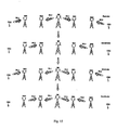
- Fig. 13 is a flowchart showing a resource allocation performed by a base station according to the second embodiment of the present invention;
- Fig. 14 is a flowchart showing a communication method of the prior art in a first comparing example according to the second embodiment of the present invention;
- Fig. 15 is a flowchart showing a communication method of the prior art in a second comparing example according to the second embodiment of the present invention;
- Fig. 16 is a flowchart showing the space division duplex communication method in a second comparing example according to the second embodiment of the present invention.
- A main idea of the present invention is to provide a cellular network based on relay station (RS) and a space division duplex communication method, wherein uplink and downlink can be multiplexed with the space independence between links created geographically and the multi-antenna RS, which can effectively improve the use efficiency of each channel and the network performance.
- Then the cellular network based on RS and the space division duplex communication method will be described with reference to the drawings.
- Fig. 5 is a schematic diagram showing a configuration of a cellular network based on RS according to a first embodiment of the present invention. This embodiment shows a case where the UE is of a two-hop user. As shown in Fig. 5, the cellular network based on RS includes a base station, a RS and a UE, wherein the base station has at least one antenna and the RS has at least two antennas.
- The base station transmits a broadcasting signal, receives a feedback signal corresponding to the broadcasting signal from the UE or from the RS, and allocates resources for the UE according to the feedback signal. Also, the base station transmits a downlink signal, receives an uplink signal from the UE or from the RS, and recovers uplink data from the UE.
- The RS receives the broadcasting signal and the downlink signal from the base station, the feedback signal corresponding to the broadcasting signal and the uplink signal from the UE. After receiving the broadcasting signal, the RS adds its identification information (such as the serial number of the RS) in the broadcasting signal and then transfers the broadcasting signal to the UE and correspondingly, after receiving the feedback signal corresponding to the broadcasting signal, the RS transfers the feedback signal to the base station. In addition, after receiving the downlink signal from the base station and/or the uplink signal from the UE in the current slot, the RS obtains the beam coefficient of the downlink signal according to the pilot signal of the downlink signal and the beam coefficient of the uplink signal according to the pilot signal of the uplink signal, transmits the uplink signal to the base station in the next slot using the beam coefficient of the downlink signal and transmits the downlink signal to the UE in the next slot using the beam coefficient of the uplink signal.
- The UE receives the broadcasting signal and the downlink signal from the base station, including the broadcasting signal and the downlink signal transmitted directly from the base station, and/or those transferred from the RS. After receiving the broadcasting signal transmitted directly from the base station and/or that transferred from the RS, the UE determines whether itself is a one-hop user (covered by the base station directly) or a multi-hop user (covered by the RS) according to the information of the broadcasting signal such as the path loss or the SINR and feeds back a feedback signal corresponding to the broadcasting signal directly to the base station or the feedback signal is transferred by the RS to the base station.
- Here, when the UE is s one-hop user, it will notify the base station about this. When the UE is a two-hop user, it will feed back the identification information (such as the serial number) of the RS covering the UE to the base station via the RS and further, the UE can feed back the feedback signal with the information of the RS (the path loss value or the SINR value etc.) to the base station.
- Fig. 6 is a flowchart showing a space division duplex communication method according to the first embodiment of the present invention. As shown in Fig. 6, the space division duplex communication method according to the present embodiment includes the following steps:
- In
step 110, the base station transmits the broadcasting signal and allocates resources for the UE according to the feedback signal corresponding to the broadcasting signal. In a case when the UE is a two-hop user, the resources allocated by the base station are two slots. After the resources are allocated, the UE, the RS and the base station begin to communicate. - In
step 120, in the first slot, the base station and the UE transmit signals to the RS at the same time and since the RS has two antennas, it can receive the downlink signal from the base station and the uplink signal from the UE at the same time, wherein the downlink signal from the base station and the uplink signal from the UE are orthogonal. - In
step 130, in the second slot, the RS transfers the downlink signal received in the first slot from the base station to the UE and at the same time, transfers the uplink signal received in the first slot from the UE to the base station. Since the RS has a function of buffering data, the signal transmitted in the second slot can be that received in the first slot or previously. - Furthermore, as shown in Fig. 7, when the base station allocates resources for the UE in
step 110, the following steps are performed: - In
step 111, the base station transmits the broadcasting signal periodically; - In
step 112, the RS attaches identification information such as its serial number that uniquely identifies itself to the received broadcasting signal and transfers the broadcasting signal from the base station; - In
step 113, the UE attempting to access the network receives the broadcasting signals from the base station and all RSs, measures the corresponding path loss or SINR respectively, determines whether itself is a one-hop user (covered by the base station) or a two-hop user (covered by a RS) according to the measured path loss or SINR and feeds back the feedback signal corresponding to the broadcasting signal directly to the base station or the feedback signal is transferred by the RS to the base station. - When the UE is a two-hop user, it will feed back the feedback signal with the identification information of the RS covering the UE to the base station and the feedback signal can further include the minimum path loss value or the maximum SINR value of the RS covering the UE.
- In
step 114, the base station allocates resources for the UE and transmits the allocation result to the UE and the RS covering the UE. - Here, when the UE is a one-hop or a multi-hop user, the resources allocated by the base station to the UE are two slots.
- In
step 114, before the base station allocates resources for the UE, it can notify the RS covering the UE to determine whether interference between the received downlink signal and the uplink signal is lower than a predetermined threshold and to feed back the determining result to the base station. - If the determining result is that the interference is lower than the predetermined threshold, the space division duplex communication method of the present embodiment can be adopted and the base station allocates two slots for the UE. If the determining result is that the interference is higher than the predetermined threshold, the methods of the prior arts can be adopted, for example, in the first communication method of the prior art the base station allocates four slots for the UE and in the second communication method of the prior art the base station allocates three slots for the UE and then communication continues with the communication method of the prior art.
- In addition, in
step 120, after receiving the above signals in the first slot, the RS can further estimate the beam coefficient of the downlink signal according to the pilot signal of the downlink signal from the base station and the beam coefficient of the uplink signal according to the pilot signal of the uplink signal from the UE respectively. - In
step 130, by further using the estimated the beam coefficient of the downlink signal from the base station and the beam coefficient of the uplink signal from the UE in the first slot, the RS can make the estimated beam coefficient of the downlink signal as the transmitting coefficient of the uplink signal, make the estimated beam coefficient of the uplink signal as the transmitting coefficient of the downlink signal and transmits the downlink signal received from the base station and the uplink signal received from the UE to the UE and the base station respectively. - It can be seen in the method according to the present embodiment, the use efficiency of each channel is 2 links per slot. Compared with the communication method in prior art, since the space division duplex communication method of the present embodiment makes fully use of the space orthogonality between the uplink signal and the downlink signal, the RS can receive the downlink signal from the base station and the uplink signal from the UE in the same slot at the same time and can transmit the downlink signal and the uplink signal in the same slot at the same time, which can effectively improve the use efficiency of each channel and the network performance.
- In order to better understand the effect of the present embodiment, the method of the prior art and the one of the present embodiment in the same condition will be compared, wherein, it is assumed that the method of the prior art and the one of the present embodiment are both applied to the space division duplex communication.
- In the first comparing example, it is assumed that the base station has one antenna and the RS has two antennas. As shown in Fig. 8, in the method of the prior art, the base station can only transmit the downlink signal to the RS in the first and the second slots respectively, which is because in the multi-antenna system of the prior art, when the orthogonality between the downlink and uplink signals is not taken into account, the number of the links transmitting at the same time is limited by the minimum number between the transmitting antennas and the receiving antennas. Therefore, although the RS has two antennas, it cannot transmit in the downlink and the uplink at the same time.
- In the third slot, the RS transmits the downlink signal to the two different UEs at the same time, and the communication system equals to a multi-antenna system with two transmitting antennas and two receiving antennas. In this case, the use efficiency of each channel of the prior art is 4 links/3 slots.
- Then Fig. 6 is referred to describe the communication method of the present invention.
- In the first slot, the base station and the UE transmit the downlink signal and to the RS respectively at the same time and with the same frequency resource, and the RS measures the beam coefficients of the downlink signal and the uplink signal according to pilot signals of the received signals respectively;
- In the second slot, the RS transmits the received uplink signal to the base station using the beam coefficient of the downlink signal measured in the first slot as the transmitting coefficient, and transmits the received uplink signal to the UE using the beam coefficient of the uplink signal measured in the first slot as the transmitting coefficient. Since the RS has the function of buffering data, the signals transmitted in the second slot can be the one received in the first slot or previously.
- Then it can be obtained that the use efficiency of each channel is 2 links per slot.
- In the second comparing example, the base station and the RS both have two antennas, therefore the communication system can use two links to transmit, for example, two downlinks or two uplinks at the same time. As shown in Fig. 9, in the method of the prior art, in the first slot, the base station transmits two downlink signals to the RS at the same time and the RS receives the two downlink signals; in the second slot, the RS transmits the two downlink signals to the two corresponding UEs. Since the uplink and the downlink are symmetrical, here only the downlink is taken to illustrate. In this case, the use efficiency of each channel of the prior art is 2 links per slot.
- In addition, the base station in Fig. 9 can communicate with two RSs at the same time, i.e. in the first slot, the base station transmits two downlink signals to the two RSs at the same time respectively and in the second slot, the each RS transfers the corresponding downlink signal to the corresponding UE.
- As shown in Fig. 10, in the communication method of the present embodiment, when the base station has a plurality of antennas, the base station can cooperate with different RSs, i.e. when the orthogonality between the downlink and uplink signals are taken into account, the RS can receive the downlink signal from the base station and the uplink signal from the UE at the same time and can transmit the downlink signal and the uplink signal in the same slot at the same time. Therefore, a base station having two antennas can communicate with two RSs each having two antennas, which improves the use efficiency.
- In Fig. 10, the base station and each RS have two antennas. In the first slot, the base station transmits
downlink signals DL 1 andDL 2 toRS 1 andRS 2 respectively; at the same time,UE 1 transmits anuplink signal UL 1 toRS 1 andUE 2 transmits an uplink signal UL2 toRS 2. Furthermore,RS 1 andRS 2 measure the beam coefficient of the signals from the base station and from the UE respectively. - In the second slot, the RSs transfer the signals from the base station and from the UEs at the same time. That is,
RS 1 transmits theuplink signal UL 1 fromUE 1 to the base station and thedownlink signal DL 1 from the base station toUE 1 respectively andRS 2 transmits theuplink signal UL 2 from UE2 to the base station and thedownlink signal DL 2 from the base station toUE 2 respectively. - At this time the use efficiency of each channel is 4 links per slot.
- The above comparison shows that compared with the prior art, the system and method according to the first embodiment of the present invention can effectively improve the use efficiency of each channel and the system performance.
- The above comparison only shows the case when a UE is a one-hop or two-hop user. The second embodiment will show the case when a UE is a three-or -more-hop user.
- Fig. 11 is a schematic diagram showing a configuration of a cellular network based on RS according to a second embodiment of the present invention. This embodiment shows the case when a UE is a three-hop user. As shown in Fig. 11, the cellular network based on RS includes a base station, a
first RS 1, asecond RS 2 and a UE, wherein the base station has at least one antenna and each RS has at least two antennas. - The base station transmits a broadcasting signal to
RS 1, receives a feedback signal corresponding to the broadcasting signal fromRS 1, and allocates resources for the UE according to the feedback signal. Also, the base station transmits a downlink signal toRS 1, receives an uplink signal fromRS 1, and recovers the uplink signal for the UE. -
RS 1 receives the broadcasting signal and the downlink signal from the base station, the feedback signal corresponding to the broadcasting signal and the uplink signal fromRS 2. After receiving the broadcasting signal,RS 1 adds its identification information (such as the serial number) in the broadcasting signal and then transfers the broadcasting signal toRS 2 and correspondingly, after receiving fromRS 2 the feedback signal corresponding to the broadcasting signal,RS 1 transfers the feedback signal to the base station. In addition, after receiving the downlink signal from the base station or the uplink signal transferred fromRS 2 in the current slot,RS 1 will transmit the downlink signal from the base station and/or the uplink signal transferred fromRS 2 toRS 2 and/or the base station respectively in the next slot. -
RS 2 receives the broadcasting signal and the downlink signal fromRS 1, the feedback signal corresponding to the broadcasting signal, and the uplink signal from the UE. After receiving the broadcasting signal fromRS 1,RS 2 adds its identification information (such as the serial number) in the broadcasting signal and then transfers the broadcasting signal to the UE and correspondingly, after receiving the feedback signal corresponding to the broadcasting signal,RS 2 transfers the feedback signal toRS 1. In addition, after receiving the downlink signal fromRS 1 and/or the uplink signal from the UE in the current slot,RS 2 will transmit the uplink signal from the UE and/or the downlink signal fromRS 1 toRS 1 and/or the UE respectively in the next slot. - The UE receives the broadcasting signal and the downlink signal from
RS 2, and transmits the feedback signal corresponding to the broadcasting signal and the uplink signal toRS 2. After receiving the broadcasting signal fromRS 2, the UE determines the number of hops of itself according to the path loss or the SINR of the broadcasting signal. In this embodiment, the UE determines itself is covered byRS 2 so it is the three-hop user. Then the UE feeds back the feedback signal with an identification information (such as the serial number) ofRS 2 covering the UE toRS 2 and the UE can further feed back the path loss value or the SINR value toRS 2 through the feedback signal. - Fig. 12 is a flowchart showing a space division duplex communication method according to the second embodiment of the present invention. As shown in Fig. 12, the space division duplex communication method according to the present embodiment includes the following steps:
- In
step 210, the base station transmits a broadcasting signal and allocates resources for the UE according to a feedback signal corresponding to the broadcasting signal. In a case when the UE is a three-hop user, the resources allocated by the base station are two slots. After the resources are allocated, the UE, the RS and the base station begin to communicate. - In
step 220, in the first slot, the base station transmits a downlink signal toRS 1 and at the same time,RS 2 transmits an uplink signal toRS 1 and a downlink signal to the UE. - In
step 230, in the second slot,RS 1 transfers the downlink signal received from the base station toRS 2 and the uplink signal received fromRS 2 to the base station and at the same time, the UE transmits an uplink signal toRS 2. - The above description is based on the assumption that the base station has only one antenna. When the base station has two or more than two antennas, the situation is quite similar and the number of the antennas of
RS 2 only needs to be more than or equal to that of the base station. For example, when the number of antennas of the base station is two, each RS has to have at least two antennas so that when the base station transmits downlink signals, the number of which equals to that of the antennas, to the same RS in the first slot at the same time, each antenna of the RS receives a corresponding downlink signal. Of course, the base station can make the downlink signal transmitted by each antenna correspond to a RS, i.e. when the base station has two antennas, the downlink signal transmitted by one is received by its corresponding RS and altogether there are two independent RSs for receiving the downlink signals transmitted from different antennas of the base station. - Furthermore, as shown in Fig. 13, when the base station allocates resources for the UE in
step 210, there are the following steps: - In
step 211, the base station transmits the broadcasting signal periodically; - In
step 212,RS 1 attaches the identification information such as its serial number that uniquely identifies itself to the received broadcasting signal and transfers the broadcasting signal from the base station; - In
step 213,RS 2 attaches the identification information such as its serial number ofRS 2 that uniquely identifies itself to the received broadcasting signal and transfers the broadcasting signal; - In
step 214, the UE attempting to access the network receives the broadcasting signal, measures the path loss or SINR, determines the number of hops of itself according to the measured path loss or SINR and feeds back the determining result toRS 2 by use of the feedback signal corresponding to the broadcasting signal. In the second embodiment of the present invention, the UE is a three-hop user. The feedback signal includes the identification information of the RS covering the UE, and further can include the minimum path loss value or the maximum SINR value. - In
step 215,RS 2 transfers the feedback signal received from the UE toRS 1. - In
step 216,RS 1 feeds back the feedback signal transferred fromRS 2 to the base station. - In
step 217, the base station allocates resources for the UE and transmits the allocation result to the UE and the corresponding RS. Here the UE is a three-hop user and the base station allocates 2 slots to the UE. - In
step 217, before the base station allocates resources for the UE, it can notify the RS covering the UE to determine whether interference between the received downlink signal and uplink signal is lower than the predetermined threshold and to feed back the determining result to the base station. - If the determining result is that the interference is lower than the predetermined threshold, the space division duplex communication method of the present invention can be adopted and the base station allocates two slots for the UE. If the determining result is that the interference is higher than the predetermined threshold, the methods of the prior arts can be adopted.
- In addition, in
step 220, after receiving the above signals in the first slot,RS 1 can further estimate the beam coefficient of the downlink signal from the base station according to the pilot signal of the downlink signal, and the beam coefficient of the uplink signal fromRS 2 according to the pilot signal of the uplink signal fromRS 2 respectively. - In
step 230, by further using the estimated the beam coefficient of the downlink signal from the base station and the beam coefficient of the uplink signal fromRS 2 in the first slot,RS 1 can make the estimated beam coefficient of the downlink signal as the transmitting coefficient of the uplink signal in the current slot, make the estimated beam coefficient of the uplink signal as the transmitting coefficient of the downlink signal in the current slot and transmits the downlink signal received from the base station and the uplink signal received fromRS 2 in the first slot toRS 2 and the base station respectively. - It can be seen in the method according to the present embodiment, the use efficiency of each channel is 3 links per slot. Compared with the communication method in prior art, since the space division duplex communication method of the present embodiment makes fully use of the space orthogonality between the uplink signal and the downlink signal, the RS can receive the downlink signal and the uplink signal in the same slot at the same time and can transmit the downlink signal and the uplink signal in the same slot at the same time, which can effectively improve the use efficiency of each channel and the network performance.
- In order to better understand the effect of the present embodiment, the method of the prior art and that of the present embodiment in the same condition will be compared, wherein, it is assumed that the method of the prior art and the one of the present embodiment are both applied to the space division duplex communication.
- In the first comparing example, it is assumed that the base station has one antenna and each RS has at least two antennas. As shown in Fig. 14, in the method of the prior art, in the first slot, the base station transmits a downlink signal to
RS 1 and at thesame time RS 2 transmits a downlink signal to the UE; in the second slot,RS 1 transfers the downlink signal received from the base station toRS 2; in the third slot,RS 1 transfers a uplink signal to the base station and at the same time the UE transmits a uplink signal toRS 2; in the fourth slot,RS 2 transfers the uplink signal received from the UE toRS 1. With the above method, the use efficiency of each channel can reach 6/4 links per slot. - As the description on Fig. 12, in this case, the use efficiency of each channel can reach 6/2 links per slot by the communication method of the present embodiment, which is obviously higher than that obtained by the prior art.
- In the second comparing example, it is assumed that the base station has two antennas and each RS has at least two antennas, therefore the communication system can use two links to transmit, for example, two downlink signals or two uplink signals at the same time. As shown in Fig. 15, in the method of the prior art, in the first slot, the base station transmits two downlink signals to
RS 1 andRS 3, each ofRS 1 andRS 3 receives one of the two downlink signals transmitted from the base station respectively, at the same time,RS 2 transmits a downlink signal toUE 1 andRS 4 transmits a downlink signal toUE 2; in the second slot,RS 1 transmits the downlink signal received from the base station toRS 2 andRS 3 transmits the downlink signal received from the base station toRS 4; in the third slot,RS 2 transmits the downlink signal received fromRS 1 to theUE 1,RS 4 transmits the downlink signal received fromRS 3 toUE 2,RS 1 transmits an uplink signal to the base station andRS 3 transmits an uplink signal to the base station; in the fourth slot,RS 2 transmits the uplink signal received fromUE 1 toRS 1 andRS 3 transmits the uplink signal received fromUE 1 toRS 3. In this case, the use efficiency of each channel of the prior art is 12/3 links per slot. - Fig. 16 shows in the communication method of the present embodiment, when the base station has a plurality of antennas, the base station can cooperate with different RSs, i.e. when the orthogonality between the downlink and uplink signals are taken into account, each RS can receive the downlink signal from the base station and the uplink signal from the UE at the same time and can transmit the downlink signal and the uplink signal in the same slot at the same time. Therefore, a base station having two antennas can communicate with two RSs, which improves the use efficiency.
- In Fig. 16, it is assumed that the base station has two antennas and each RS has at least two antennas. In the first slot, the base station transmits different downlink signals to
RS 1 andRS 3 respectively,RS 2 transmits an uplink signal toRS 1 and a downlink signal toUE 1 andRS 4 transmits an uplink signal toRS 3 and a downlink signal toUE 2; in the second slot,RS 1 transmits the downlink signal received from the base station toRS 2 and the uplink signal received fromRS 2 to the base station,RS 3 transmits the downlink signal received from the base station toRS 4 and the uplink signal received fromRS 4 to the base station,UE 1 transmits an uplink signal toRS 2 andUE 2 transmits an uplink signal toRS 4. And the use efficiency of each channel is 12/2 links per slot. - The above comparison shows that compared with the prior art, the system and method according to the second embodiment of the present invention can effectively improve the use efficiency of each channel and the system performance.
- The above description shows the present invention is not limited to that the RS can transmit the uplink and downlink signals at the same time. The focus is that the uplink and downlink signals can be transmitted and received at the same time with the space independence between links created geographically and the RS with multiple antennas. Furthermore, the RS can make a beam coefficient of the downlink and/or uplink signal estimated in the current slot as a beam coefficient of the downlink and/or uplink signal in the next or subsequent slot. Therefore, for those skilled in the art, based on the prior art, the present invention can be extended to the case that the UE is beyond three hops.
- Generally speaking, compared with the prior art, in the case that the UE is a multi-hop user, the present invention can effectively improve the use efficiency of each channel and the network performance. Furthermore, in the present invention no matter the UE is a one-hop user, a two-hop user or a three-hop user, the base station allocates two slots to the UE. Since the UE of the cellular network based on RS is usually a one-hop user, a two-hop user or a three-hop user, there is no need to perform the special processing on different cases, which can simplify the complexity in system design.
- It should be appreciated that the descriptions are just embodiments rather than limitations to the present invention. It will be apparent to those skilled in the art that various modifications and variations can be made. Thus, it is intended that the present invention covers the modifications and variations of this invention provided they come within the scope of the appended claims and their equivalents.
Claims (15)
- A cellular network based on relay station, comprising a base station, a relay station and a user equipment, wherein the base station has at least one antenna and the relay station has at least two antennas, wherein,
the base station allocates resources for the user equipment, transmits a downlink signal in a current slot and receives an uplink signal from the user equipment through the relay station in the next slot;
the relay station receives the downlink signal from the base station and the uplink signal from the user equipment in the current slot and transmits the received downlink signal to the user equipment and the uplink signal to the base station in the next slot;
the user equipment transmits the uplink signal in the current slot and receives the downlink signal through the relay station in the next slot,
wherein the uplink signal and the downlink signal transmitted in the same slot are orthogonal. - The cellular network according to claim 1, wherein after receiving the downlink signal from the base station and the uplink signal from the user equipment in the current slot, the relay station obtains corresponding beam coefficients of the downlink and the uplink signals according to pilot signals of the downlink and the uplink signals, transmits the uplink signal to the base station in the next slot using the beam coefficient of the downlink signal obtained in the current slot and transmits the downlink signal to the user equipment in the next slot using the beam coefficient of the uplink signal obtained in the current slot.
- A space division duplex communication method, comprising steps of:step a, at a base station, transmitting a broadcasting signal and allocating resources for a user equipment according to a feedback signal corresponding to the broadcasting signal;step b, transmitting a downlink signal from the base station and an uplink signal from the user equipment to a relay station in a current slot;step c, at the relay station, transmitting the downlink signal received from the base station to the user equipment and the uplink signal received from the user equipment to the base station in the next slot,wherein the uplink signal and the downlink signal transmitted in the same slot are orthogonal.
- The method according to claim 3, wherein,
in step b, the relay station further estimates beam coefficients of the downlink and the uplink signals according to pilot signals of the downlink and the uplink signals in the current slot; and
in step c, the relay station transmits the uplink signal received from the user equipment to the base station in the next slot using the beam coefficient of the downlink signal obtained in the current slot and transmits the downlink signal received from the base station to the user equipment in the next slot using the beam coefficient of the uplink signal obtained in the current slot. - The method according to claim 3 or 4, wherein step a further comprises:step a1, at the base station, transmitting the broadcasting signal periodically;step a2, at the relay station, attaching an identification information to the received broadcasting signal and transferring the broadcasting signal from the base station;step a3, at the user equipment, feeding back the feedback signal with the identification information of the relay station covering the user equipment to the base station; andstep a4, at the base station, allocating resources for the user equipment and transmitting the allocation result to the user equipment and the corresponding relay station.
- The method according to claim 5, wherein the identification information comprises a serial number of the relay station.
- The method according to claim 6, wherein the feedback signal further comprises a path loss value or a SINR value of the relay station covering the user equipment.
- A cellular network based on relay station, comprising a base station, a first relay station, a second relay station and a user equipment, wherein the base station has at least one antenna and each relay station has at least two antennas, wherein
the base station allocates resources for the user equipment, transmits a downlink signal in a current slot and receives an uplink signal from the first relay station in the next slot;
the first relay station receives the downlink signal from the base station and the uplink signal from the second relay station in the current slot and transmits the downlink signal to the second relay station and the uplink signal to the base station in the next slot;
the second relay station transmits the uplink signal to the first relay station and the downlink signal to the user equipment in the current slot and transmits the received downlink signal to the user equipment and the received uplink signal to the first relay station in the next slot;
the user equipment receives the downlink signal from the second relay station in the current slot and transmits the uplink signal in the next slot,
wherein the uplink signal and the downlink signal transmitted in the same slot are orthogonal. - The cellular network according to claim 8, wherein after receiving the downlink signal and the uplink signal in the current slot, the relay station obtains beam coefficients of the downlink and the uplink signals according to pilot signals of the downlink and the uplink signals, transmits the uplink signal in the next slot using the beam coefficient of the downlink signal and transmits the downlink signal in the next slot using the beam coefficient of the uplink signal.
- A space division duplex communication method, comprising steps of:step A, at a base station, transmitting a broadcasting signal and allocating resources for a user equipment according to a feedback signal corresponding to the broadcasting signal;step B, transmitting a downlink signal from the base station to a first relay station, and at the same time, transmitting from a second relay station an uplink signal to the first relay station and a downlink signal to a user equipment;step C, at the first relay station, transmitting the downlink signal received from the base station to the second relay station and the uplink signal received from the second relay station to the base station in the current slot to the base station in the next slot, and at the same time, transmitting the uplink signal from the user equipment to the second relay station,wherein the uplink signal and the downlink signal transmitted in the same slot are orthogonal.
- The method according to claim 10, wherein,
in step B, the first relay station further estimates corresponding beam coefficients of the downlink and the uplink signals according to pilot signals of the downlink and the uplink signals in the current slot; and
in step C, the first relay station transmits the uplink signal received from the second relay station to the base station in the next slot using the beam coefficient of the downlink signal and transmits the downlink signal from the base station to the second relay station in the next slot using the beam coefficient of the uplink signal. - The method according to claim 10 or 11, wherein step A further comprises:step A1, at the base station, transmitting the broadcasting signal periodically;step A2, at the relay station, attaching an identification information to the received broadcasting signal and transferring the broadcasting signal from the base station;step A3, at the user equipment, feeding back the feedback signal with the identification information of the relay station covering the user equipment to the base station;step A4, at the base station, allocating resources for the user equipment and transmitting the allocation result to the user equipment and the corresponding relay station.
- The method according to claim 12, wherein the identification information comprises a serial number of the relay station.
- The method according to claim 13, wherein the feedback signal further comprises a path loss value or a SINR value of the relay station covering the user equipment.
- A cellular network based on relay station, comprising a base station, a plurality of relay stations and a user equipment, wherein the base station has at least one antenna and each relay station has at least two antennas, wherein
at least one relay station among the plurality of relay stations receives a downlink signal from the base station or from the other relay stations and an uplink signal from the user equipment or from the other relay stations in the current slot, and transmits the received downlink signal to the other relay stations or to the user equipment and the received uplink signal to the other relay stations or to the base station in the next slot; and
at least one relay station among the plurality of relay stations transmits the downlink signal to the other relay stations or to the user equipment and the uplink signal to the other relay stations or to the base station in the current slot, and receives the downlink signal from the base station or from the other relay stations and the uplink signal from the user equipment or from the other relay stations in the next slot,
wherein the uplink signal and the downlink signal transmitted in the same slot are orthogonal.
Priority Applications (1)
| Application Number | Priority Date | Filing Date | Title |
|---|---|---|---|
| EP08018910A EP2040496B1 (en) | 2006-07-12 | 2007-07-11 | Cellular network based on relay station and space division duplex communication method |
Applications Claiming Priority (1)
| Application Number | Priority Date | Filing Date | Title |
|---|---|---|---|
| CN2006101018760A CN101106807B (en) | 2006-07-12 | 2006-07-12 | A cellular network based on relay and space division duplex communication method |
Related Child Applications (2)
| Application Number | Title | Priority Date | Filing Date |
|---|---|---|---|
| EP08018910A Division EP2040496B1 (en) | 2006-07-12 | 2007-07-11 | Cellular network based on relay station and space division duplex communication method |
| EP08018910.3 Division-Into | 2008-10-29 |
Publications (3)
| Publication Number | Publication Date |
|---|---|
| EP1912450A2 true EP1912450A2 (en) | 2008-04-16 |
| EP1912450A3 EP1912450A3 (en) | 2008-07-02 |
| EP1912450B1 EP1912450B1 (en) | 2010-08-25 |
Family
ID=39000428
Family Applications (2)
| Application Number | Title | Priority Date | Filing Date |
|---|---|---|---|
| EP07013626A Expired - Fee Related EP1912450B1 (en) | 2006-07-12 | 2007-07-11 | Cellular network based on relay station and space division duplex communication method |
| EP08018910A Expired - Fee Related EP2040496B1 (en) | 2006-07-12 | 2007-07-11 | Cellular network based on relay station and space division duplex communication method |
Family Applications After (1)
| Application Number | Title | Priority Date | Filing Date |
|---|---|---|---|
| EP08018910A Expired - Fee Related EP2040496B1 (en) | 2006-07-12 | 2007-07-11 | Cellular network based on relay station and space division duplex communication method |
Country Status (5)
| Country | Link |
|---|---|
| US (1) | US7974240B2 (en) |
| EP (2) | EP1912450B1 (en) |
| JP (1) | JP4982277B2 (en) |
| CN (1) | CN101106807B (en) |
| DE (2) | DE602007009236D1 (en) |
Cited By (7)
| Publication number | Priority date | Publication date | Assignee | Title |
|---|---|---|---|---|
| WO2010051539A2 (en) * | 2008-10-31 | 2010-05-06 | Research In Motion Limited | Layer 2 relay multiplexing and interference mitigation |
| EP2272182A2 (en) * | 2008-04-29 | 2011-01-12 | Samsung Electronics Co., Ltd. | Methods and apparatus for network coding in a communication system |
| WO2011018557A3 (en) * | 2009-08-14 | 2011-04-14 | Nokia Corporation | Method and apparatus for managing interference handling overhead |
| GB2478810A (en) * | 2009-12-31 | 2011-09-21 | Intel Corp | Distributed simultaneous transmit and receive relay station |
| CN102884731A (en) * | 2010-04-06 | 2013-01-16 | 三星电子株式会社 | Apparatus and method for spatial division duplex (SDD) for millimeter wave communication system |
| US9178608B2 (en) | 2009-11-09 | 2015-11-03 | Saab Ab | Method in wireless network using relays |
| CN110401516A (en) * | 2018-04-24 | 2019-11-01 | 上海朗帛通信技术有限公司 | A kind of first node that be used to wirelessly communicate, the method and apparatus in base station |
Families Citing this family (60)
| Publication number | Priority date | Publication date | Assignee | Title |
|---|---|---|---|---|
| US9699688B2 (en) * | 2007-08-02 | 2017-07-04 | Qualcomm Incorporated | Method for scheduling orthogonally over multiple hops |
| KR101467844B1 (en) * | 2007-11-14 | 2014-12-03 | 삼성전자주식회사 | Method for transmitting data in a relay system and system therefor |
| CN101500246B (en) * | 2008-01-31 | 2010-12-29 | 大唐移动通信设备有限公司 | Data transceiving method and apparatus based on communication system provided with relay station |
| EP2085962A2 (en) | 2008-02-01 | 2009-08-05 | Yamaha Corporation | Sound absorbing structure and vehicle component having sound absorbing properties |
| US8509162B2 (en) * | 2008-02-13 | 2013-08-13 | Qualcomm Incorporated | System and method for scheduling over multiple hops |
| CN101516063B (en) * | 2008-02-21 | 2012-10-10 | 中兴通讯股份有限公司 | Multimedia broadcast and multicast service transmitting method |
| US8457549B2 (en) * | 2008-02-29 | 2013-06-04 | Lingna Holdings Pte., Llc | Multi-user MIMO relay protocol with self-interference cancellation |
| KR20090097268A (en) * | 2008-03-11 | 2009-09-16 | 엘지전자 주식회사 | A method for transmitting data in a multiple antenna system |
| FR2929781B1 (en) * | 2008-04-04 | 2011-09-02 | Thales Sa | RELAY STATION WITH DOUBLE RADIO. |
| US20110069655A1 (en) * | 2008-05-29 | 2011-03-24 | Tetsu Ikeda | Relay station apparatus, multihop system and relaying method |
| JP5117293B2 (en) * | 2008-06-19 | 2013-01-16 | シャープ株式会社 | Base station apparatus, relay station apparatus, and communication system |
| JP5138099B2 (en) * | 2008-07-30 | 2013-02-06 | エルジー エレクトロニクス インコーポレイティド | Relay station and operation method of relay station in wireless communication system |
| TW201012108A (en) * | 2008-08-18 | 2010-03-16 | Agency Science Tech & Res | Analog space-time relay method and apparatus for a wireless communication relay channel |
| KR101527977B1 (en) * | 2008-10-27 | 2015-06-15 | 엘지전자 주식회사 | Method of operating relay in wireless communication system |
| KR101432734B1 (en) * | 2008-11-04 | 2014-08-21 | 삼성전자주식회사 | Data transmission system for forwarding data using a plurality of antennas |
| KR101473758B1 (en) | 2008-11-28 | 2014-12-17 | 삼성전자주식회사 | Data transmission system for transmitting data via relay having multiple antennas |
| KR101155629B1 (en) | 2008-12-18 | 2012-06-13 | 한국전자통신연구원 | Method for selective transmit/receive antenna repetition |
| US8929303B2 (en) * | 2009-04-06 | 2015-01-06 | Samsung Electronics Co., Ltd. | Control and data channels for advanced relay operation |
| CN101867944B (en) * | 2009-04-17 | 2012-10-03 | 电信科学技术研究院 | Method and system for scheduling resources, evolved node B (eNB) and relay node (RN) |
| WO2010118705A1 (en) * | 2009-04-17 | 2010-10-21 | 大唐移动通信设备有限公司 | Resource scheduling method and system, base station and relay node |
| CN101888701B (en) * | 2009-05-11 | 2013-01-02 | 普天信息技术研究院有限公司 | Method for avoiding uplink interference |
| WO2010137926A2 (en) | 2009-05-29 | 2010-12-02 | 엘지전자 주식회사 | Method and apparatus for transmitting control information from relay node on backhaul uplink |
| CN101932103B (en) | 2009-06-19 | 2015-08-12 | 中兴通讯股份有限公司 | A kind of method of via node access |
| JP5909843B2 (en) | 2009-08-10 | 2016-04-27 | ソニー株式会社 | COMMUNICATION SYSTEM, COMMUNICATION DEVICE, COMMUNICATION METHOD, AND COMPUTER PROGRAM |
| JP2011066874A (en) | 2009-08-17 | 2011-03-31 | Sony Corp | Communication system, communication apparatus, communication method, and computer program |
| KR101650749B1 (en) * | 2009-08-18 | 2016-08-24 | 삼성전자주식회사 | Method and apparatus for allocation and indication of control channel in backhaul subframe for relay |
| JP2011071963A (en) | 2009-08-26 | 2011-04-07 | Sony Corp | Communication system, apparatus and method and computer program |
| WO2011035797A1 (en) * | 2009-09-24 | 2011-03-31 | Universität Duisburg-Essen | Method, relay station and system for transmitting signals between a first signal source and a second signal source |
| CN102098790A (en) * | 2009-12-09 | 2011-06-15 | 三星电子株式会社 | Resource scheduling information exchange method for wireless relay stations |
| CN102118757B (en) * | 2009-12-31 | 2013-11-06 | 中兴通讯股份有限公司 | Wireless relay device and method for communicating wireless relay device with base station and terminal |
| US8295335B2 (en) * | 2009-12-31 | 2012-10-23 | Intel Corporation | Techniques to control uplink power |
| US20110209183A1 (en) * | 2010-02-25 | 2011-08-25 | Samsung Electronics Co., Ltd. | Method and apparatus for transmitting data based on audio/video interface |
| WO2011129417A1 (en) * | 2010-04-16 | 2011-10-20 | 京セラ株式会社 | Communication system, communication relay device, and communication control method |
| JP5563373B2 (en) * | 2010-05-25 | 2014-07-30 | 日本電信電話株式会社 | Radio relay system, relay station apparatus, and radio relay method |
| EP3860280A1 (en) * | 2010-06-04 | 2021-08-04 | Board of Regents, The University of Texas System | Wireless communication method and appartus |
| US9794949B2 (en) | 2010-07-30 | 2017-10-17 | Board Of Regents, The University Of Texas System | Distributed rate allocation and collision detection in wireless networks |
| JP5612449B2 (en) * | 2010-11-26 | 2014-10-22 | 京セラ株式会社 | Radio relay apparatus and radio communication method |
| CN102595451A (en) * | 2011-01-04 | 2012-07-18 | 中国移动通信集团公司 | Data transmission optimization method and system thereof, and apparatuses |
| WO2012122508A2 (en) | 2011-03-09 | 2012-09-13 | Board Of Regents | Network routing system, method, and computer program product |
| GB2493328B (en) * | 2011-07-08 | 2015-12-23 | Sca Ipla Holdings Inc | Mobile communications network, mobile communicatons device, relay node and method |
| KR20130020102A (en) | 2011-08-19 | 2013-02-27 | 삼성전자주식회사 | A relay and a terminal in a multi-pair two-way relay network and a communicaton method thereof |
| CN104025656B (en) * | 2011-12-07 | 2018-08-17 | 爱立信(中国)通信有限公司 | Method and central base station for the interference management in cellular network |
| CN103379064B (en) * | 2012-04-28 | 2018-04-20 | 上海交通大学 | A kind of method for precoding, system and device |
| US9119074B2 (en) * | 2012-06-05 | 2015-08-25 | Qualcomm Incorporated | Uplink downlink resource partitions in access point design |
| CN103595520B (en) * | 2012-08-16 | 2017-08-04 | 华为技术有限公司 | Communication device and its Space Division Duplex method |
| CN104429156B (en) * | 2013-06-28 | 2019-03-26 | 华为技术有限公司 | A kind of method for building up of wireless network, equipment and system |
| US9319957B1 (en) * | 2013-07-31 | 2016-04-19 | Sprint Spectrum L.P. | Dynamic swapping of uplink and downlink base stations |
| WO2015168428A1 (en) * | 2014-05-02 | 2015-11-05 | Convida Wireless, Llc | Apparatus and method of using time reuse frame structures for multi-hop communications |
| US9621253B2 (en) * | 2014-05-09 | 2017-04-11 | Empire Technology Development Llc | Single slot bi-directional message exchange in relay networks |
| JP2016054349A (en) * | 2014-09-02 | 2016-04-14 | 株式会社東芝 | Radio communication device, radio communication system, and slot allocation method |
| JP6471005B2 (en) | 2015-03-05 | 2019-02-13 | 株式会社東芝 | Wireless communication apparatus and system |
| JP6462558B2 (en) | 2015-11-12 | 2019-01-30 | 株式会社東芝 | Wireless communication apparatus and wireless communication system |
| CN108432327B (en) * | 2016-01-08 | 2021-06-29 | 富士通株式会社 | Communication system, communication method and base station |
| CN106656217A (en) * | 2016-12-02 | 2017-05-10 | 华南理工大学 | Full-duplex transmission method for multi-radio frequency unit base station system |
| CN110011774B (en) | 2017-12-21 | 2021-10-22 | 华硕电脑股份有限公司 | Method and apparatus for backhaul link transmission and reception in wireless communication system |
| JP7148556B2 (en) * | 2018-02-09 | 2022-10-05 | パナソニック インテレクチュアル プロパティ コーポレーション オブ アメリカ | Communication device and communication method |
| US11856433B2 (en) | 2018-02-25 | 2023-12-26 | Lg Electronics Inc. | Method for transmitting/receiving signal in wireless communication system, and device therefor |
| CN110392352A (en) * | 2018-04-18 | 2019-10-29 | 海能达通信股份有限公司 | A kind of communication means of communication terminal, communication terminal and storage device |
| JP6524304B2 (en) * | 2018-04-23 | 2019-06-05 | 株式会社東芝 | Wireless communication apparatus, wireless communication system, wireless communication method and program |
| EP3818774A4 (en) | 2018-07-05 | 2022-03-16 | Lenovo (Beijing) Limited | Method and apparatus for backhaul link switching |
Citations (2)
| Publication number | Priority date | Publication date | Assignee | Title |
|---|---|---|---|---|
| US20040165676A1 (en) | 2003-02-25 | 2004-08-26 | Ranganathan Krishnan | Transmission schemes for multi-antenna communication systems utilizing multi-carrier modulation |
| WO2004102891A1 (en) | 2003-05-15 | 2004-11-25 | Telefonaktiebolaget Lm Ericsson (Publ) | Interference cancellation in wireless relaying networks |
Family Cites Families (17)
| Publication number | Priority date | Publication date | Assignee | Title |
|---|---|---|---|---|
| WO1997024884A2 (en) * | 1995-12-29 | 1997-07-10 | Ericsson Inc. | Time compressing transponder |
| AU708348B2 (en) * | 1996-03-18 | 1999-08-05 | General Instrument Corporation | Dynamic bandwidth allocation for a communication network |
| US6778507B1 (en) * | 1999-09-01 | 2004-08-17 | Qualcomm Incorporated | Method and apparatus for beamforming in a wireless communication system |
| JP3954367B2 (en) * | 2000-12-01 | 2007-08-08 | 株式会社日立コミュニケーションテクノロジー | Wireless communication method and wireless communication system using beam direction variable antenna |
| US6850499B2 (en) * | 2001-01-05 | 2005-02-01 | Qualcomm Incorporated | Method and apparatus for forward power control in a communication system |
| JP3967084B2 (en) * | 2001-02-26 | 2007-08-29 | 株式会社日立国際電気 | TDMA relay system |
| SE0303602D0 (en) | 2003-12-30 | 2003-12-30 | Ericsson Telefon Ab L M | Method and arrangement in self-organizing cooperative network |
| US7990905B2 (en) * | 2003-12-30 | 2011-08-02 | Nokia Corporation | Communication system using relay base stations with asymmetric data links |
| JP4394474B2 (en) * | 2004-02-16 | 2010-01-06 | 株式会社エヌ・ティ・ティ・ドコモ | Wireless relay system, wireless relay device, and wireless relay method |
| US7962095B2 (en) | 2004-03-31 | 2011-06-14 | Nortel Networks Limited | Relaying system and method with partner relays and selective transmission |
| KR101053610B1 (en) * | 2004-06-25 | 2011-08-03 | 엘지전자 주식회사 | Radio resource allocation method of OPDM / OPDM system |
| JP4385223B2 (en) * | 2004-06-30 | 2009-12-16 | 日本電気株式会社 | MOBILE COMMUNICATION SYSTEM, BASE STATION CONTROL DEVICE, TRANSMISSION POWER CONTROL METHOD USED FOR THEM, AND PROGRAM THEREOF |
| SE0403218D0 (en) * | 2004-12-30 | 2004-12-30 | Ericsson Telefon Ab L M | Method and apparatus related to communication |
| RU2007136114A (en) * | 2005-03-29 | 2009-04-10 | Мацусита Электрик Индастриал Ко., Лтд. (Jp) | COMMUNICATION SYSTEM, RETRAY DEVICE AND METHOD OF RELAY |
| US7406060B2 (en) * | 2005-07-06 | 2008-07-29 | Nortel Networks Limited | Coverage improvement in wireless systems with fixed infrastructure based relays |
| US7778607B2 (en) * | 2005-10-31 | 2010-08-17 | The Mitre Corporation | Echo MIMO: a method for optimal multiple input multiple output channel estimation and matched cooperative beamforming |
| JP4799228B2 (en) * | 2005-12-02 | 2011-10-26 | 株式会社エヌ・ティ・ティ・ドコモ | Communication node, radio communication system, and data relay method |
-
2006
- 2006-07-12 CN CN2006101018760A patent/CN101106807B/en not_active Expired - Fee Related
-
2007
- 2007-07-10 US US11/827,178 patent/US7974240B2/en active Active
- 2007-07-11 DE DE602007009236T patent/DE602007009236D1/en active Active
- 2007-07-11 EP EP07013626A patent/EP1912450B1/en not_active Expired - Fee Related
- 2007-07-11 DE DE602007008659T patent/DE602007008659D1/en active Active
- 2007-07-11 EP EP08018910A patent/EP2040496B1/en not_active Expired - Fee Related
- 2007-07-12 JP JP2007182942A patent/JP4982277B2/en active Active
Patent Citations (2)
| Publication number | Priority date | Publication date | Assignee | Title |
|---|---|---|---|---|
| US20040165676A1 (en) | 2003-02-25 | 2004-08-26 | Ranganathan Krishnan | Transmission schemes for multi-antenna communication systems utilizing multi-carrier modulation |
| WO2004102891A1 (en) | 2003-05-15 | 2004-11-25 | Telefonaktiebolaget Lm Ericsson (Publ) | Interference cancellation in wireless relaying networks |
Cited By (17)
| Publication number | Priority date | Publication date | Assignee | Title |
|---|---|---|---|---|
| EP2272182A2 (en) * | 2008-04-29 | 2011-01-12 | Samsung Electronics Co., Ltd. | Methods and apparatus for network coding in a communication system |
| EP2272182A4 (en) * | 2008-04-29 | 2014-02-19 | Samsung Electronics Co Ltd | Methods and apparatus for network coding in a communication system |
| US8687528B2 (en) | 2008-10-31 | 2014-04-01 | Blackberry Limited | Layer 2 relay multiplexing and interference mitigation |
| WO2010051539A3 (en) * | 2008-10-31 | 2010-08-05 | Research In Motion Limited | Layer 2 relay multiplexing and interference mitigation |
| WO2010051539A2 (en) * | 2008-10-31 | 2010-05-06 | Research In Motion Limited | Layer 2 relay multiplexing and interference mitigation |
| CN102265693A (en) * | 2008-10-31 | 2011-11-30 | 捷讯研究有限公司 | Layer 2 relay multiplexing and interference mitigation |
| CN102265693B (en) * | 2008-10-31 | 2014-12-31 | 黑莓有限公司 | Layer 2 relay multiplexing and interference mitigation |
| WO2011018557A3 (en) * | 2009-08-14 | 2011-04-14 | Nokia Corporation | Method and apparatus for managing interference handling overhead |
| US8948077B2 (en) | 2009-08-14 | 2015-02-03 | Nokia Corporation | Method and apparatus for managing interference handling overhead |
| US9178608B2 (en) | 2009-11-09 | 2015-11-03 | Saab Ab | Method in wireless network using relays |
| GB2478810B (en) * | 2009-12-31 | 2012-03-21 | Intel Corp | Distributed simultaneous transmit and receive relay system |
| GB2478810A (en) * | 2009-12-31 | 2011-09-21 | Intel Corp | Distributed simultaneous transmit and receive relay station |
| CN102884731A (en) * | 2010-04-06 | 2013-01-16 | 三星电子株式会社 | Apparatus and method for spatial division duplex (SDD) for millimeter wave communication system |
| CN102884731B (en) * | 2010-04-06 | 2017-05-10 | 三星电子株式会社 | Apparatus and method for spatial division duplex (SDD) for millimeter wave communication system |
| US9806789B2 (en) | 2010-04-06 | 2017-10-31 | Samsung Electronics Co., Ltd. | Apparatus and method for spatial division duplex (SDD) for millimeter wave communication system |
| CN110401516A (en) * | 2018-04-24 | 2019-11-01 | 上海朗帛通信技术有限公司 | A kind of first node that be used to wirelessly communicate, the method and apparatus in base station |
| CN110401516B (en) * | 2018-04-24 | 2021-10-29 | 上海朗帛通信技术有限公司 | Method and device used in first node and base station for wireless communication |
Also Published As
| Publication number | Publication date |
|---|---|
| JP2008022558A (en) | 2008-01-31 |
| US20080013520A1 (en) | 2008-01-17 |
| CN101106807A (en) | 2008-01-16 |
| DE602007008659D1 (en) | 2010-10-07 |
| US7974240B2 (en) | 2011-07-05 |
| EP1912450A3 (en) | 2008-07-02 |
| EP1912450B1 (en) | 2010-08-25 |
| EP2040496B1 (en) | 2010-09-15 |
| EP2040496A1 (en) | 2009-03-25 |
| DE602007009236D1 (en) | 2010-10-28 |
| JP4982277B2 (en) | 2012-07-25 |
| CN101106807B (en) | 2012-04-11 |
Similar Documents
| Publication | Publication Date | Title |
|---|---|---|
| EP1912450B1 (en) | Cellular network based on relay station and space division duplex communication method | |
| US7519029B2 (en) | Radio communication system, base station, relay station, mobile station, and packet transmission control method | |
| EP1650883A2 (en) | Method for transmission scheme selection based on the number of antennas and the data rate | |
| US8160013B2 (en) | Method of transmitting data in multi-cell cooperative wireless communication system | |
| US8233398B2 (en) | Apparatus and method for transmitting frame information in multi-hop relay broadband wireless access communication system | |
| EP3154310B1 (en) | System and method for one cell to cover multiple areas | |
| KR101066326B1 (en) | Scheduling apparatus and method in distributed antenna systems | |
| US20080167075A1 (en) | Method and system for control channel beamforming | |
| US20070072600A1 (en) | Method and system for reporting link state in a communication system | |
| US20120281657A1 (en) | Method for downlink multi-antenna multi-base station interference coordination and base station | |
| JP2008530946A (en) | Method and apparatus for cooperative relay | |
| TW200537859A (en) | Wireless multi-hop system with macroscopic multiplexing | |
| JP4118699B2 (en) | Wireless communication method and wireless communication system | |
| JP2009284478A (en) | Method for allocating power to source station and relay stations in two-hop amplify-and-forward relay multi-input-multi-output networks | |
| US7848276B2 (en) | Apparatus and method for supporting relay service in multihop relay broadband wireless access (BWA) communication system | |
| WO2017124898A1 (en) | Hybrid wave beam training method, station and terminal | |
| US9426811B2 (en) | Method and device for avoiding inter-cell interference in a wireless access system | |
| Akoum et al. | Cognitive cooperation for the downlink of frequency reuse small cells | |
| KR20080084313A (en) | Apparatus and method for spatial multiplexing in relay broadband wireless communication system | |
| Bal et al. | Execution of hybrid noma schemes concerning outage performance and sum rate interplay | |
| Bestak et al. | An interference cancellation scheme for D2D multi-link communication underlaying cellular network | |
| CN101730128B (en) | Method and device for selecting resource processing mode | |
| KR20220167917A (en) | Wireless signal transmission method combining CNOMA-OAM for improving channel capacity | |
| KR20150007219A (en) | Apparatus and method for broadcasting data transmission on LTE D2D communications | |
| KR20150007235A (en) | Apparatus and method for multi-hop on LTE D2D communications |
Legal Events
| Date | Code | Title | Description |
|---|---|---|---|
| PUAI | Public reference made under article 153(3) epc to a published international application that has entered the european phase |
Free format text: ORIGINAL CODE: 0009012 |
|
| AK | Designated contracting states |
Kind code of ref document: A2 Designated state(s): AT BE BG CH CY CZ DE DK EE ES FI FR GB GR HU IE IS IT LI LT LU LV MC MT NL PL PT RO SE SI SK TR |
|
| AX | Request for extension of the european patent |
Extension state: AL BA HR MK RS |
|
| PUAL | Search report despatched |
Free format text: ORIGINAL CODE: 0009013 |
|
| AK | Designated contracting states |
Kind code of ref document: A3 Designated state(s): AT BE BG CH CY CZ DE DK EE ES FI FR GB GR HU IE IS IT LI LT LU LV MC MT NL PL PT RO SE SI SK TR |
|
| AX | Request for extension of the european patent |
Extension state: AL BA HR MK RS |
|
| 17P | Request for examination filed |
Effective date: 20081029 |
|
| AKX | Designation fees paid |
Designated state(s): DE GB |
|
| 17Q | First examination report despatched |
Effective date: 20090217 |
|
| GRAP | Despatch of communication of intention to grant a patent |
Free format text: ORIGINAL CODE: EPIDOSNIGR1 |
|
| RIC1 | Information provided on ipc code assigned before grant |
Ipc: H04W 40/22 20090101AFI20100114BHEP |
|
| RIC1 | Information provided on ipc code assigned before grant |
Ipc: H04W 40/22 20090101AFI20100216BHEP |
|
| GRAS | Grant fee paid |
Free format text: ORIGINAL CODE: EPIDOSNIGR3 |
|
| GRAA | (expected) grant |
Free format text: ORIGINAL CODE: 0009210 |
|
| AK | Designated contracting states |
Kind code of ref document: B1 Designated state(s): DE GB |
|
| REG | Reference to a national code |
Ref country code: GB Ref legal event code: FG4D |
|
| REF | Corresponds to: |
Ref document number: 602007008659 Country of ref document: DE Date of ref document: 20101007 Kind code of ref document: P |
|
| PLBE | No opposition filed within time limit |
Free format text: ORIGINAL CODE: 0009261 |
|
| STAA | Information on the status of an ep patent application or granted ep patent |
Free format text: STATUS: NO OPPOSITION FILED WITHIN TIME LIMIT |
|
| 26N | No opposition filed |
Effective date: 20110526 |
|
| REG | Reference to a national code |
Ref country code: DE Ref legal event code: R097 Ref document number: 602007008659 Country of ref document: DE Effective date: 20110526 |
|
| PGFP | Annual fee paid to national office [announced via postgrant information from national office to epo] |
Ref country code: DE Payment date: 20180626 Year of fee payment: 12 |
|
| PGFP | Annual fee paid to national office [announced via postgrant information from national office to epo] |
Ref country code: GB Payment date: 20180711 Year of fee payment: 12 |
|
| REG | Reference to a national code |
Ref country code: DE Ref legal event code: R119 Ref document number: 602007008659 Country of ref document: DE |
|
| GBPC | Gb: european patent ceased through non-payment of renewal fee |
Effective date: 20190711 |
|
| PG25 | Lapsed in a contracting state [announced via postgrant information from national office to epo] |
Ref country code: GB Free format text: LAPSE BECAUSE OF NON-PAYMENT OF DUE FEES Effective date: 20190711 Ref country code: DE Free format text: LAPSE BECAUSE OF NON-PAYMENT OF DUE FEES Effective date: 20200201 |