WO2020004088A1 - 灌流装置および灌流方法 - Google Patents
灌流装置および灌流方法 Download PDFInfo
- Publication number
- WO2020004088A1 WO2020004088A1 PCT/JP2019/023752 JP2019023752W WO2020004088A1 WO 2020004088 A1 WO2020004088 A1 WO 2020004088A1 JP 2019023752 W JP2019023752 W JP 2019023752W WO 2020004088 A1 WO2020004088 A1 WO 2020004088A1
- Authority
- WO
- WIPO (PCT)
- Prior art keywords
- perfusion
- organ
- perfusate
- pump
- kidney
- Prior art date
- Legal status (The legal status is an assumption and is not a legal conclusion. Google has not performed a legal analysis and makes no representation as to the accuracy of the status listed.)
- Ceased
Links
Images



Classifications
-
- A—HUMAN NECESSITIES
- A01—AGRICULTURE; FORESTRY; ANIMAL HUSBANDRY; HUNTING; TRAPPING; FISHING
- A01N—PRESERVATION OF BODIES OF HUMANS OR ANIMALS OR PLANTS OR PARTS THEREOF; BIOCIDES, e.g. AS DISINFECTANTS, AS PESTICIDES OR AS HERBICIDES; PEST REPELLANTS OR ATTRACTANTS; PLANT GROWTH REGULATORS
- A01N1/00—Preservation of bodies of humans or animals, or parts thereof
- A01N1/10—Preservation of living parts
-
- F—MECHANICAL ENGINEERING; LIGHTING; HEATING; WEAPONS; BLASTING
- F04—POSITIVE - DISPLACEMENT MACHINES FOR LIQUIDS; PUMPS FOR LIQUIDS OR ELASTIC FLUIDS
- F04B—POSITIVE-DISPLACEMENT MACHINES FOR LIQUIDS; PUMPS
- F04B49/00—Control, e.g. of pump delivery, or pump pressure of, or safety measures for, machines, pumps, or pumping installations, not otherwise provided for, or of interest apart from, groups F04B1/00 - F04B47/00
- F04B49/08—Regulating by delivery pressure
Definitions
- the present invention relates to a perfusion apparatus and a perfusion method for preserving an organ by perfusion.
- various preservation methods and perfusion methods have been developed in order to preserve the removed organ in a transplantable state.
- a simple cooling method in which blood in the organ is replaced with a low-temperature organ preservation solution in order to suppress cell metabolism and then immersed in a low-temperature preservation solution is known.
- a perfusion preservation method is known in which an organ preservation solution is perfused into an intravascular vascular network for the purpose of removing waste products from a stored organ.
- Patent Document 1 A conventional perfusion apparatus for preserving an organ by perfusion is described in, for example, Patent Document 1.
- a perfusion solution sent from a reservoir to a roller pump through a glass oxygenator is perfused into the liver via a cannula after oxygenation and removal of an air embolus.
- Patent Document 1 Conventionally, as described in Patent Document 1, various devices have been devised in order to preserve an organ to be perfused in a better condition.
- the state of the removed organ is significantly different between the case where the removal is performed from the living body and the case where the removal is performed after the death of the donor.
- the state of the organ also differs depending on the state of the donor and the state at the time of extraction.
- the present invention has been made in view of such circumstances, and has as its object to provide a technique for preserving an extracted organ in a better state.
- a first invention of the present application is a perfusion apparatus for perfusing an organ with a perfusion solution, comprising a reservoir for storing the perfusion solution, and an inflow for flowing the perfusion solution from the reservoir to the organ.
- a pressure measurement unit that measures pressure
- a control unit that controls the pumping amount of the pump, wherein the control unit controls the pump so that the measurement value of the pressure measurement unit does not exceed a predetermined threshold. Feedback control is performed for this.
- a second invention of the present application is the perfusion apparatus according to the first invention, wherein the threshold value is 130 mmHg or less.
- 3A third invention of the present application is the perfusion apparatus according to the first invention, wherein the threshold value is 100 mmHg or less.
- 4A fourth invention of the present application is the perfusion apparatus according to the first invention, wherein the control unit sets a pumping amount of the pump to be equal to or less than an average blood flow supplied to the organ in a healthy body.
- 5A fifth invention of the present application is the perfusion apparatus according to the first invention, wherein the target organ is a kidney, and the control unit controls the pump to deliver a fluid of 8 ml or less per minute.
- the sixth invention of the present application is the perfusion apparatus according to the first invention or the fifth invention, wherein the target organ is a kidney, and the threshold value is 100 mmHg or less.
- a seventh invention of the present application is the perfusion apparatus according to the first invention, comprising the two inflow pipes, wherein the target organ is a liver, and one of the inflow pipes is connected to a portal vein of the liver.
- the other of the inflow pipes is connected to the hepatic artery of the liver, the threshold value in the inflow pipe connected to the portal vein is 40 mmHg or less, and the threshold value in the inflow pipe connected to the hepatic artery is Is 500 mmHg or less.
- An eighth invention of the present application is a perfusion method for perfusing an organ with a perfusion solution, comprising the steps of: a) measuring the pressure of the perfusion solution at the most downstream side in an inflow pipe for flowing the perfusion solution into the organ; b) performing a feedback control of a pump that sends the perfusate in the inflow pipe so that the measured value in the step a) does not exceed a predetermined threshold.
- the organ it is possible to prevent the organ from being damaged by the inflow of the perfusate. Therefore, the removed organ can be preserved in a better state.
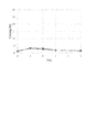
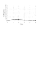
- FIG. 3 is a diagram showing the time course of kidney urea nitrogen concentration in an experiment. It is a figure showing time course of the creatinine concentration of the kidney in an experiment.
- FIG. 3 is a diagram showing the time course of kidney urea nitrogen concentration in an experiment.
- FIG. 3 is a diagram showing the time course of kidney urea nitrogen concentration in an experiment. It is the schematic which showed the structure of the perfusion apparatus which concerns on 2nd Embodiment.
- “donor” and “recipient” may be a human or a non-human animal. That is, in the present application, the “organ” including “kidney” and “liver” may be a human organ or a non-human animal organ.
- the non-human animal may be a rodent including a mouse and a rat, an ungulate including a pig, a goat and a sheep, a non-human primate including a chimpanzee, and other non-human mammals. Other animals may be used.
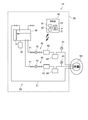
- FIG. 1 is a schematic diagram showing a configuration of the perfusion apparatus 1.
- the perfusion device 1 is a device for temporarily storing an organ such as a kidney extracted from a donor outside the body until it is transplanted to a recipient.
- the perfusion apparatus 1 includes a housing 20, a reservoir 30, a perfusate inlet 40, a perfusate outlet 50, and a controller 60.
- the perfusion apparatus 1 is an apparatus for performing a perfusion process on an extracted organ.
- the organ to be perfused is the kidney 9.
- the organ to be perfused may be a liver or another organ.
- the housing 20 houses the reservoir 30, the perfusate inflow section 40 excluding a part of the inflow pipe 41, and the perfusion fluid discharge section 50 excluding a part of the discharge pipe 51.
- the reservoir 30 is a container for storing a perfusate.
- a temperature control mechanism 31 and a gas exchange mechanism 32 are provided around the reservoir 30.
- the temperature adjusting mechanism 31 adjusts the temperature of the perfusate stored in the reservoir 30.
- the gas exchange mechanism 32 supplies gas such as oxygen to the perfusion solution stored in the reservoir 30 to dissolve the gas in the perfusion solution.
- the gas exchange mechanism 32 may be inserted into an inflow pipe 41 of the perfusate inflow section 40, which will be described later.
- An ETK solution is used as the perfusion solution of the present embodiment. Note that other types of perfusate may be used as the perfusate.
- the perfusate inlet 40 supplies the perfusate from the reservoir 30 to the kidney 9.
- the perfusate inflow section 40 includes an inflow pipe 41, a pump 42, a temperature adjustment unit 43, a deaeration unit 44, and a pressure gauge 45.
- the pump 42, the temperature adjustment unit 43, the deaeration unit 44, and the pressure gauge 45 are inserted into the inflow pipe 41.
- the perfusate inflow section 40 is disposed inside the housing 20 except for a part of the inflow pipe 41.
- One end of the inflow pipe 41 is connected to the reservoir 30.
- the other end of the inflow pipe 41 is connected to an organ to be perfused during the perfusion process.
- the other end of the inflow pipe 41 is connected to the renal artery of the kidney 9.
- the perfusate is supplied from the reservoir 30 to the renal artery of the kidney 9 via the inflow pipe 41.
- the pump 42 generates a flow of the perfusate flowing from the reservoir 30 to the kidney 9 in the inflow pipe 41.
- the pump 42 of the present embodiment is a pump equipped with a brushless motor. As a result, it is possible to stably control the amount of perfusate to be sent in units of 1 ml / min.
- the temperature adjusting unit 43 adjusts the temperature of the perfusate in the inflow pipe 41.
- the temperature adjusting unit 43 immerses a part of the inflow pipe 41 in a liquid having a set temperature of, for example, 4 ° C., 20 ° C., or 37 ° C., so that the perfusate in the inflow pipe 41 is set to the set temperature. adjust.
- the deaeration unit 44 removes gas components of the perfusate in the inflow pipe 41.
- the pressure gauge 45 is disposed downstream of the pump 42, the temperature adjustment unit 43, and the deaeration unit 44 inserted in the inflow pipe 41. That is, the pressure gauge 45 is arranged on the most downstream side of the inflow pipe 41. That is, the pressure gauge 45 is a pressure measuring unit that measures the pressure of the perfusate at the most downstream side in the inflow pipe 41. Thereby, the pressure of the perfusate can be measured at the site closest to the kidney 9 to be perfused in the inflow pipe 41.
- the perfusate discharging unit 50 discharges the perfusate from the kidney 9.
- the perfusate discharge section 50 has a discharge pipe 51.
- One end of the discharge pipe 51 is connected to an organ to be perfused during the perfusion process.
- one end of the discharge pipe 51 is connected to a renal vein of the kidney 9.
- the other end of the discharge pipe 51 is connected to the reservoir 30.
- a pump for generating a flow of the perfusate flowing from the kidney 9 toward the reservoir 30 may be inserted in the discharge pipe 51.
- the perfusion apparatus 1 of the present embodiment has a configuration in which the perfusate discharged from the kidney 9 is returned to the reservoir 30, but the present invention is not limited to this.
- the perfusate discharged from the kidney 9 may be discarded or stored in another container without being returned to the reservoir 30.
- the reservoir 30, the perfusate inflow section 40, or the perfusion solution discharge section 50 may include a measurement unit for detecting pH or a specific component.
- the perfusate inlet 40 and the perfusate outlet 50 may include a flow meter for measuring the flow rate of the perfusate.
- an electromagnetic valve for controlling communication may be interposed in the inflow pipe 41 and the discharge pipe 51.
- the control unit 60 is a part for controlling the operation of each unit in the perfusion apparatus 1.
- the control unit 60 of the present embodiment is configured by a computer having an arithmetic processing unit 61 such as a CPU, a memory 62 such as a RAM, and a storage unit 63 such as a hard disk drive. ing.
- the control unit 60 is electrically connected to the temperature adjustment mechanism 31, the gas exchange mechanism 32, the pump 42, the temperature adjustment unit 43, the deaeration unit 44, and the pressure gauge 45, respectively.
- the control unit 60 controls the amount of liquid sent from the pump 42. Specifically, the control unit 60 controls the amount of liquid sent from the pump 42 by performing feedback control so that the measured value of the pressure gauge 45 does not exceed a predetermined threshold.
- the perfusion apparatus 1 may be used for performing a perfusion process while performing an operation of removing and transplanting an organ.
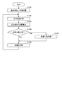
- FIG. 2 is a flowchart showing a flow of a perfusion process of the kidney 9 using the perfusion apparatus 1.
- FIG. 3 is a diagram illustrating a schematic example of a time lapse between a liquid supply amount of the pump 42 and a pressure value measured by the pressure gauge 45 in the perfusion process.
- a kidney 9 referred to as a “first kidney” that has been removed and started perfusion after cardiac arrest is indicated by a solid line, and a kidney 9 (“second kidney”) whose perfusion started immediately after removal from a healthy living body. ) Is indicated by a dashed line.
- the threshold value of the pressure of the perfusate at the most downstream side of the inflow pipe 41 is set to 100 mmHg. Further, the maximum value of the amount of perfusate delivered to the renal artery of the kidney 9 is set to 8 ml / min.
- the control unit 60 operates the pump 42 so that the pumping amount gradually increases from 0 ml / min.
- the pumping amount (initial flow rate) of the pump 42 at the start of perfusion is, for example, 1 ml / min or 2 ml / min, which is sufficiently smaller than the maximum value of 8 ml / min, instead of 0 ml / min. It may be. It is preferable that the pumping amount of the pump 42 at the start of perfusion be sufficiently smaller than the maximum value of the pumping amount.
- control unit 60 After the start of perfusion in step S101, the control unit 60 causes the pressure gauge 45 to measure the pressure of the perfusate at the most downstream side in the inflow pipe 41 (step S102). Then, the control unit 60 starts monitoring the pressure value measured by the pressure gauge 45.
- control unit 60 performs feedback control on the pump 42 so that the pressure value, which is the measurement value of the pressure gauge 45, does not exceed the threshold value (100 mmHg), and the liquid supply amount of the pump 42 gradually increases. Is calculated (step S103).
- the calculation of the liquid sending amount in step S103 may be based on proportional control, or may be based on other feedback control such as PI control or PID control.
- control unit 60 determines whether or not the amount of the pump 42 calculated in step S103 is equal to or less than the maximum value (8 ml / min) (step S104). If the control unit 60 determines that the pumping amount of the pump 42 calculated in step S103 is equal to or less than the maximum value (8 ml / min), the control unit 60 proceeds to step S106, and determines the pumping amount of the pump 42 in step S103. It changes so that it may become the calculated liquid sending (step S106).
- step S104 if it is determined in step S104 that the pumping amount of the pump 42 calculated in step S103 is larger than the maximum value (8 ml / min), the pumping amount of the pump 42 is determined to the maximum value (8 ml / min) (step S104). S105). Then, the control unit 60 proceeds to step S106, and changes the liquid supply amount of the pump 42 to the maximum value (8 ml / min) determined in step S105 (step S106).
- step S106 Updating the liquid supply amount of the pump 42 in step S106, the control unit 60 returns to step S102 and continues the feedback control.
- This perfusion apparatus 1 performs a perfusion process by connecting the inflow pipe 41 and the discharge pipe 51 to the blood vessel of the organ during or after the extirpation operation for extracting the organ from the donor. For example, when removing an organ from a healthy living donor, if the organ is connected to the perfusion apparatus 1 during the removal operation and a perfusion process is performed, the temperature of the organ and the state in the blood vessel are compared with the state in the healthy living body. Close.
- the control unit 60 performs feedback control on the pump 42 so that the pressure of the perfusate on the most downstream side in the inflow pipe 41 does not exceed a predetermined threshold.
- a pressure value close to the pressure in the blood vessel of the organ can be obtained.
- the pressure value in the blood vessel may increase, and the blood vessel or organ may be burdened.
- the control unit 60 sets the pumping amount of the pump 42 to 8 ml / min or less, which is the maximum value.
- the volume of the liquid is 10% or less of the average blood flow supplied to the kidney 9 in the healthy body.
- the removed organ is likely to be in a worse condition than in a healthy body. For this reason, if more perfusate is supplied than the blood flow in the healthy body, it may burden the organ. Therefore, it is preferable that the pumping amount of the pump 42 be equal to or less than the average blood flow supplied to the organ in the healthy body. In order to further reduce the burden on the removed organ, it is more preferable that the pumping amount of the pump 42 be equal to or less than half the average blood flow provided to the organ in a healthy body.
- the condition of each blood vessel is good, so that the flow path resistance is rapidly reduced, and the pumping amount of the pump 42 is relatively quickly increased to the maximum value as compared with the first kidney. (8 ml / min).
- the pumping amount of the pump 42 is set to the maximum value (8 ml / min). take time.
- the amount of perfusion of the pump 42 is appropriately determined in accordance with the state of the kidney 9 in order to control the pressure value of the perfusate supplied to the kidney 9 so as not to exceed the threshold value. Therefore, with this perfusion apparatus 1, even if it is the first kidney, it is possible to suppress the flow rate from being too large and imposing a burden on blood vessels and tissues.
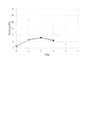
- FIG. 4 is a diagram showing the time course of the creatinine concentration in the kidney in Experiment 1.
- FIG. 5 is a diagram showing the time course of kidney urea nitrogen concentration (BUN) in Experiment 1.
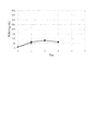
- FIG. 6 is a diagram showing the time course of creatinine concentration in the kidney in Experiment 2.
- FIG. 7 is a diagram showing the time course of kidney urea nitrogen concentration (BUN) in Experiment 2.
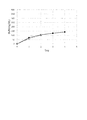
- FIG. 8 is a diagram showing the time course of the creatinine concentration in the kidney in Experiment 3.
- FIG. 9 is a diagram showing the time course of kidney urea nitrogen concentration (BUN) in Experiment 3.
- the threshold value of the measurement value of the pressure gauge 45 is preferably 100 mmHg or less.
- the threshold value is preferably smaller than the blood pressure band in a healthy living body of the blood vessel to which the inflow pipe is connected.
- the threshold is preferably equal to or lower than 130 mmHg, which is the lower limit of the normal systolic blood pressure band in the aorta.
- the threshold is set to 100 mmHg or less, which is the lower limit of the systolic blood pressure band of low blood pressure. Note that the threshold is not limited to the organ that has been verified.
- FIG. 10 is a schematic diagram showing the configuration of the perfusion apparatus 1A.
- the perfusion apparatus 1A has two perfusion liquid inflow sections 40.
- Other configurations of the perfusion apparatus 1A are the same as those of the perfusion apparatus 1 according to the first embodiment.
- This perfusion apparatus 1A is used, for example, to perform a perfusion process on the liver 9A.
- two inflow pipes 41 are connected to the portal vein and the hepatic artery of the liver 9A, respectively.
- the discharge pipe 51 is connected to the upper hepatic inferior vena cava (SH-IVC) or the lower hepatic inferior vena cava (IH-IVC) of the liver 9A.
- the hepatic artery is an arterial system, and the pressure of blood in the hepatic artery is large.
- the portal vein is a venous system, and the pressure of blood in the portal vein is much smaller than the pressure in the hepatic artery. For this reason, in this perfusion apparatus 1A, the threshold value of the pressure of the perfusate in the inflow pipe 41 connected to the hepatic artery and the threshold value of the pressure of the perfusate in the inflow pipe 41 connected to the portal vein are individually set. .
- the control unit 60 sets the threshold value of the pressure of the perfusate to 500 mmHg or less for the pump 42 inserted in the inflow pipe 41 connected to the hepatic artery of the liver 9A, Is controlled with the maximum value of 240 to 360 ml / min.
- the control unit 60 sets the threshold value of the pressure of the perfusate to 40 mmHg or less, and sets the maximum value of the amount of perfusate to be sent. Is controlled as 840 to 960 ml / min.
- the threshold of the pressure of the perfusate and the maximum value of the amount of perfusate may be different for each of the inflow pipes 41.
- Some organs to be perfused may have a plurality of inflow blood vessels having different blood pressure values in the living body.
- the threshold value of the pressure of the perfusate or the maximum value of the amount of liquid delivered may be set according to each blood vessel.
- the perfusion apparatus 1 according to the first embodiment has one inflow pipe 41 and one outflow pipe 51. Further, the perfusion apparatus 1A according to the second embodiment has two inflow pipes 41 and one discharge pipe 51. However, the present invention is not limited to this. In the perfusion apparatus of the present invention, the number of the perfusate inflow portion and the number of the perfusion solution discharge portion may be one or more.
- the pipe connected to the reservoir was directly connected to the blood vessel of the organ. That is, the end of the pipe connected to the reservoir served as a cannula.
- a separate member cannula may be connected to the distal ends of the inflow pipe and the discharge pipe, and the cannula may be connected to a blood vessel.
Landscapes
- Engineering & Computer Science (AREA)
- Life Sciences & Earth Sciences (AREA)
- Mechanical Engineering (AREA)
- General Engineering & Computer Science (AREA)
- Health & Medical Sciences (AREA)
- Dentistry (AREA)
- General Health & Medical Sciences (AREA)
- Wood Science & Technology (AREA)
- Zoology (AREA)
- Environmental Sciences (AREA)
- Agricultural Chemicals And Associated Chemicals (AREA)
- Control Of Positive-Displacement Pumps (AREA)
Abstract
この灌流装置(1)は、灌流液を貯留するリザーバー(30)と、リザーバー(30)から臓器(9)へと灌流液を流入させる流入配管(41)と、臓器(9)から灌流液を排出させる排出配管(51)と、流入配管(41)内においてリザーバー(30)から臓器(9)へ灌流液を送液するポンプ(42)と、流入配管(41)内の最も下流側において灌流液の圧力を計測する圧力計測部(45)と、ポンプ(42)の送液量を制御する制御部(60)とを有する。制御部(60)は、圧力計測部(45)の計測値が所定の閾値を超えないようにポンプ(42)に対してフィードバック制御を行う。これにより、臓器が灌流液の流入によってダメージを受けることを抑制できる。したがって、摘出された臓器をより良い状態で保存することができる。
Description
本発明は、臓器を灌流保存するための灌流装置および灌流方法に関する。
臓器移植などの各種の手術において、摘出された臓器を移植可能な状態で保存するため、種々の保存方法や灌流方法が開発されている。摘出した臓器を保存するための方法として、例えば、細胞の代謝を抑制するために臓器内血液を低温の臓器保存液に置き換えてから、低温の保存液に浸漬する単純冷却法が知られている。また、保存している臓器内の老廃物の除去を目的として、臓器内血管網に臓器保存液を灌流させる灌流保存法が知られている。
従来の臓器を灌流保存するための灌流装置は、例えば、特許文献1に記載されている。特許文献1の灌流装置では、貯蔵器からガラス酸素供給器を通してローラポンプに送られた灌流溶液が、酸素付加および空気塞栓の除去後カニューレを介して肝臓へと灌流される。
従来、特許文献1に記載のように、灌流の対象となる臓器をより良い状態で保存するために、種々の工夫がなされている。しかしながら、摘出後すぐに灌流装置と繋いだ場合であっても、生体から摘出した場合と、ドナーの死後に摘出を行った場合とで、摘出された臓器の状態は大きく異なる。また、ドナーの状態や摘出時の状況によっても、臓器の状態が異なる。
本発明は、このような事情に鑑みなされたものであり、摘出された臓器をより良い状態で保存する技術を提供することを目的とする。
上記課題を解決するため、本願の第1発明は、臓器に灌流液を灌流させる灌流装置であって、前記灌流液を貯留するリザーバーと、前記リザーバーから前記臓器へと前記灌流液を流入させる流入配管と、前記臓器から前記灌流液を排出させる排出配管と、前記流入配管内において前記リザーバーから前記臓器へ前記灌流液を送液するポンプと、前記流入配管内の最も下流側において前記灌流液の圧力を計測する圧力計測部と、前記ポンプの送液量を制御する制御部と、を有し、前記制御部は、前記圧力計測部の計測値が所定の閾値を超えないように前記ポンプに対してフィードバック制御を行う。
本願の第2発明は、第1発明の灌流装置であって、前記閾値は、130mmHg以下である。
本願の第3発明は、第1発明の灌流装置であって、前記閾値は、100mmHg以下である。
本願の第4発明は、第1発明の灌流装置であって、前記制御部は、前記ポンプの送液量を、健常体内における前記臓器に供給される平均血流量以下とする。
本願の第5発明は、第1発明の灌流装置であって、対象とする前記臓器が腎臓であり、前記制御部は、前記ポンプの送液量を、毎分8ml以下とする。
本願の第6発明は、第1発明または第5発明の灌流装置であって、対象とする前記臓器が腎臓であり、前記閾値は、100mmHg以下である。
本願の第7発明は、第1発明の灌流装置であって、2つの前記流入配管を有し、対象とする前記臓器が肝臓であり、前記流入配管の一方は、前記肝臓の門脈に接続され、前記流入配管の他方は、前記肝臓の肝動脈に接続され、前記門脈に接続される前記流入配管における前記閾値は40mmHg以下であり、前記肝動脈に接続される前記流入配管における前記閾値は500mmHg以下である。
本願の第8発明は、臓器に灌流液を灌流させる灌流方法であって、a)前記臓器へ前記灌流液を流入させる流入配管内の最も下流側における前記灌流液の圧力を計測する工程と、b)前記工程a)における計測値が所定の閾値を超えないように、前記流入配管内において前記灌流液を送液するポンプをフィードバック制御する工程と、を有する。
本願の第1発明から第8発明によれば、臓器が灌流液の流入によってダメージを受けることを抑制できる。したがって、摘出された臓器をより良い状態で保存することができる。
以下、本発明の実施形態について、図面を参照しつつ説明する。本願において「ドナー」および「レシピエント」は、ヒトであってもよいし、非ヒト動物であってもよい。すなわち、本願において、「腎臓」および「肝臓」を含む「臓器」は、ヒトの臓器であってもよいし、非ヒト動物の臓器であってもよい。また、非ヒト動物は、マウスおよびラットを含む齧歯類、ブタ、ヤギおよびヒツジを含む有蹄類、チンパンジーを含む非ヒト霊長類、その他の非ヒトほ乳動物であってもよいし、ほ乳動物以外の動物であってもよい。
<1.第1実施形態>
<1-1.灌流装置の構成>
本発明の第1実施形態に係る灌流装置1について、図1を参照しつつ説明する。図1は、灌流装置1の構成を示した概略図である。この灌流装置1は、ドナーから摘出した腎臓等の臓器を、レシピエントへ移植するまでの間、体外で一時的に保存するための装置である。
<1-1.灌流装置の構成>
本発明の第1実施形態に係る灌流装置1について、図1を参照しつつ説明する。図1は、灌流装置1の構成を示した概略図である。この灌流装置1は、ドナーから摘出した腎臓等の臓器を、レシピエントへ移植するまでの間、体外で一時的に保存するための装置である。
図1に示すように、灌流装置1は、筐体20と、リザーバー30と、灌流液流入部40と、灌流液排出部50と、制御部60とを有する。灌流装置1は、摘出された臓器に対して灌流処理を行うための装置である。本実施形態では、灌流対象となる臓器は、腎臓9である。なお、灌流対象となる臓器は、肝臓や、その他の臓器であってもよい。
筐体20は、リザーバー30と、流入配管41の一部を除く灌流液流入部40と、排出配管51の一部を除く灌流液排出部50とを収容する。
リザーバー30は、灌流液を貯留する容器である。リザーバー30の周囲には、温度調節機構31およびガス交換機構32が備えられる。温度調節機構31は、リザーバー30内に貯留される灌流液の温度を調整する。ガス交換機構32は、リザーバー30に貯留される灌流液に酸素等の気体を供給して、灌流液に気体を溶解させる。なお、ガス交換機構32は、灌流液流入部40の後述する流入配管41に介挿されてもよい。本実施形態の灌流液には、ETK液が用いられる。なお、灌流液には、その他の種類の灌流液が用いられてもよい。
灌流液流入部40は、リザーバー30から腎臓9へと灌流液を供給する。灌流液流入部40は、流入配管41、ポンプ42、温度調整ユニット43、脱気ユニット44および圧力計45を含む。ポンプ42、温度調整ユニット43、脱気ユニット44および圧力計45は、流入配管41に介挿される。灌流液流入部40は、流入配管41の一部を除いて、筐体20の内部に配置される。
流入配管41は、一端がリザーバー30に接続される。流入配管41の他端は、灌流処理時には、灌流対象となる臓器に接続される。本実施形態では、流入配管41の他端は、腎臓9の腎動脈に接続される。これにより、リザーバー30から流入配管41を介して腎臓9の腎動脈へと灌流液が供給される。
ポンプ42は、流入配管41内にリザーバー30から腎臓9へと向かう灌流液の流れを発生させる。本実施形態のポンプ42は、ブラシレスモータを搭載したポンプである。これにより、灌流液の送液量を1ml/分単位で安定して制御することが可能である。
温度調整ユニット43は、流入配管41内の灌流液の温度を調整する。温度調整ユニット43は、例えば、4℃、20℃、37℃等の設定された温度の液体内に流入配管41の一部を浸すことにより、流入配管41内の灌流液を設定された温度に調整する。脱気ユニット44は、流入配管41内の灌流液の気体成分を除去する。
圧力計45は、流入配管41に介挿されるポンプ42、温度調整ユニット43および脱気ユニット44よりも下流側に配置される。すなわち、圧力計45は、流入配管41の最も下流側に配置される。つまり、圧力計45は、流入配管41内の最も下流側において灌流液の圧力を計測する圧力計測部である。これにより、流入配管41内で、灌流対象である腎臓9に最も近い部位において灌流液の圧力を計測することができる。
灌流液排出部50は、腎臓9から灌流液を排出させる。灌流液排出部50は、排出配管51を有する。排出配管51の一端は、灌流処理時には、灌流対象となる臓器に接続される。本実施形態では、排出配管51の一端は、腎臓9の腎静脈に接続される。排出配管51の他端は、リザーバー30に接続される。これにより、腎臓9の腎静脈から排出される灌流液が、排出配管51を介してリザーバー30へと還流される。排出配管51には、腎臓9からリザーバー30へと向かう灌流液の流れを発生させるポンプが介挿されていてもよい。
本実施形態の灌流装置1は、腎臓9から排出された灌流液をリザーバー30へと還流させる構成であったが、本発明はこれに限られない。腎臓9から排出された灌流液は、リザーバー30へと還流させず、廃棄したり、他の容器に貯留したりしてもよい。
なお、リザーバー30、灌流液流入部40または灌流液排出部50は、pHや、特定の成分を検出するための計測ユニットを備えていてもよい。また、灌流液流入部40および灌流液排出部50は、灌流液の流量を計測するための流量計を備えていてもよい。また、流入配管41および排出配管51には、連通を制御するための電磁弁が介挿されていてもよい。
制御部60は、灌流装置1内の各部を動作制御するための部位である。図1中に概念的に示したように、本実施形態の制御部60は、CPU等の演算処理部61、RAM等のメモリ62、および、ハードディスクドライブ等の記憶部63を有するコンピュータにより構成されている。制御部60は、温度調節機構31、ガス交換機構32、ポンプ42、温度調整ユニット43、脱気ユニット44、および圧力計45と、それぞれ電気的に接続される。
灌流処理時には、制御部60は、ポンプ42の送液量を制御する。具体的には、制御部60は、圧力計45の計測値が所定の閾値を超えないようにフィードバック制御を行うことにより、ポンプ42の送液量を制御する。
なお、この灌流装置1は、臓器の摘出手術および移植手術を行いながら灌流処理を行うために用いてもよい。
<1-2.腎臓の灌流処理時の流量制御について>
次に、本実施形態の灌流装置1を用いた腎臓9の灌流処理について、図2および図3を参照しつつ説明する。図2は、灌流装置1を用いた腎臓9の灌流処理の流れを示したフローチャートである。図3は、灌流処理におけるポンプ42の送液量と、圧力計45の計測した圧力値との時間経過の模式的な一例を示した図である。図3において、心停止後に摘出して灌流を開始した腎臓9(「第1腎臓」と称する)の例を実線で、健康な生体から摘出直後に灌流を開始した腎臓9(「第2腎臓」と称する)の例を一点鎖線で示している。
次に、本実施形態の灌流装置1を用いた腎臓9の灌流処理について、図2および図3を参照しつつ説明する。図2は、灌流装置1を用いた腎臓9の灌流処理の流れを示したフローチャートである。図3は、灌流処理におけるポンプ42の送液量と、圧力計45の計測した圧力値との時間経過の模式的な一例を示した図である。図3において、心停止後に摘出して灌流を開始した腎臓9(「第1腎臓」と称する)の例を実線で、健康な生体から摘出直後に灌流を開始した腎臓9(「第2腎臓」と称する)の例を一点鎖線で示している。
本実施形態では、流入配管41の最も下流側における灌流液の圧力の閾値を100mmHgとする。また、腎臓9の腎動脈に対する灌流液の送液量の最大値を8ml/分とする。流入配管41を腎臓9の腎動脈に接続し、かつ、排出配管51を腎臓9の腎静脈に接続した後に、灌流を開始する(ステップS101)。すなわち、制御部60は、ポンプ42の駆動を開始する。なお、リザーバー30の温度調節機構31およびガス交換機構32と、灌流液流入部40の温度調整ユニット43および脱気ユニット44とは、ステップS101の開始前に予め駆動を開始させておく。
ステップS101の灌流開始時において、制御部60は、ポンプ42を、その送液量が0ml/分から徐々に大きくなるように動作させる。なお、灌流開始時におけるポンプ42の送液量(初期流量)は、0ml/分に代えて、例えば、1ml/分や2ml/分等、最大値である8ml/分よりも十分小さい送液量であってもよい。灌流開始時におけるポンプ42の送液量は、送液量の最大値よりも十分小さいことが好ましい。
ステップS101における灌流の開始後、制御部60は、圧力計45に流入配管41内の最も下流側における灌流液の圧力を計測させる(ステップS102)。そして、制御部60は、圧力計45の計測する圧力値のモニタリングを開始する。
続いて、制御部60は、圧力計45の計測値である圧力値が閾値(100mmHg)を超えないように、かつ、ポンプ42の送液量が徐々に上昇するように、フィードバック制御によりポンプ42の送液量の設定値を算出する(ステップS103)。なお、ステップS103における送液量の算出は、比例制御に基づいてもよいし、PI制御やPID制御等のその他のフィードバック制御に基づいてもよい。
その後、制御部60は、ステップS103で算出したポンプ42の送液量が最大値(8ml/分)以下であるか否かを判断する(ステップS104)。そして、ステップS103で算出したポンプ42の送液量が最大値(8ml/分)以下であると判断すると、制御部60は、ステップS106へと進み、ポンプ42の送液量を、ステップS103で算出した送液となるように変更する(ステップS106)。
一方、ステップS104において、ステップS103で算出したポンプ42の送液量が最大値(8ml/分)より大きいと判断すると、ポンプ42の送液量を最大値(8ml/分)に決定する(ステップS105)。そして、制御部60は、ステップS106へと進み、ポンプ42の送液量を、ステップS105で決定した最大値(8ml/分)となるように変更する(ステップS106)。
ステップS106においてポンプ42の送液量を更新すると、制御部60はステップS102へと戻り、フィードバック制御を継続する。
この灌流装置1は、ドナーから臓器を摘出する摘出手術中、あるいは摘出手術後に、流入配管41および排出配管51を臓器の血管に接続することで、灌流処理を行う。例えば健康な生体ドナーから臓器を摘出する場合に、摘出手術中から臓器を灌流装置1に接続して灌流処理を行えば、当該臓器の温度や血管内の状態は健康な生体内の状態に比較的近い。
しかしながら、健康な生体ドナーから臓器を摘出する場合であっても、摘出手術後に灌流処理を開始する場合、一度臓器内の血流が止まった状態となった後に、臓器内の血管に灌流液を流すこととなる。この場合、健康な体内における血流量と同じ流量の灌流液を突然流すと、血管や臓器にとって負担となる場合がある。
また、心停止後時間の経過したドナーから臓器を摘出した場合、健康な生体内の状態に比べ、臓器の温度が低下したり、臓器内の血管壁の柔軟性が低下する。このため、健康な体内における血流量よりも小さな流量であっても、灌流液の流量によっては血管や臓器にとって負担となる場合がある。
そこで、この灌流装置1では、制御部60が、流入配管41内の最も下流側における灌流液の圧力が所定の閾値を超えないように、ポンプ42に対してフィードバック制御を行う。圧力計45によって流入配管41のうち臓器に近い部分の圧力を計測することにより、臓器の血管内における圧力に近似した圧力値を得ることができる。血管壁の弾力性の低下が生じている場合には、灌流液の流量が小さくても、血管内圧力値が大きくなり血管や臓器に負担がかかる虞がある。そこで、流入配管41内の最も下流側における圧力が所定の閾値を超えないようにすることにより、臓器の血管内における圧力が所定の閾値を大きく超えることを抑制できる。したがって、臓器が灌流液の流入によってダメージを受けることを抑制できる。すなわち、摘出された臓器をより良い状態で保存することができる。
また、この灌流装置1では、制御部60が、ポンプ42の送液量を、最大値である8ml/分以下とする。当該送液量は、健常体内において腎臓9に供給される平均血流量の10%以下である。摘出された臓器は、健常体内における状態よりも状態が悪い可能性が高い。このため、健常体内における血流量よりも多くの灌流液が送液されると、臓器にとって負担となる場合がある。そこで、ポンプ42の送液量は、健常体内における臓器に供給される平均血流量以下であることが好ましい。摘出された臓器の負担をさらに軽減するために、ポンプ42の送液量は、健常体内における臓器に提供される平均血流量の半分以下であることがより好ましい。
灌流開始前の腎臓9において、各血管内の血液の流れが止まっているため、灌流開始後に次第にポンプ42の送液量を上昇させると、図3に示すように、止まっている血流が抵抗となって圧力値がすぐに閾値である100mmHgに達する。その後、時間の経過とともに、腎臓9の各血管内における灌流液の流れが生じ、流路抵抗が下がることにより、圧力計45の計測する圧力値が下がる。
図3に示すように、第2腎臓では、各血管の状態が良好であるため、流路抵抗が迅速に低下し、第1腎臓と比べて、ポンプ42の送液量を比較的速く最大値(8ml/分)とすることが可能である。それに対して、第1腎臓は、第2腎臓と比べて各血管の状態が良好でないため、流路抵抗は低下し難く、ポンプ42の送液量を最大値(8ml/分)とするのに時間がかかる。この灌流装置1では、腎臓9に供給される灌流液の圧力値が閾値を超えないように制御するため、腎臓9の状態に合わせて適切にポンプ42の送液量が決定される。したがって、この灌流装置1では、第1腎臓であっても、流量が大きすぎて血管や組織に負担がかかることを抑制できる。
<1-3.腎臓の灌流処理実験について>
ここで、図4~図9を参照しつつ、灌流液の送液量と、灌流対象である腎臓の状態を示す指標との関係を調べた実験結果について説明する。以下の実験1~3では、いずれも、生体から摘出したブタの腎臓を用いて実験を行った。
実験1:水頭差を利用した点滴による腎動脈への灌流液の供給(検体数2)
実験2:高流量(25~35ml/分)での灌流処理(検体数2)
実験3:低流量(100mmHg以下、6~8ml/分)での灌流処理(検体数2)
ここで、図4~図9を参照しつつ、灌流液の送液量と、灌流対象である腎臓の状態を示す指標との関係を調べた実験結果について説明する。以下の実験1~3では、いずれも、生体から摘出したブタの腎臓を用いて実験を行った。
実験1:水頭差を利用した点滴による腎動脈への灌流液の供給(検体数2)
実験2:高流量(25~35ml/分)での灌流処理(検体数2)
実験3:低流量(100mmHg以下、6~8ml/分)での灌流処理(検体数2)
図4は、実験1における腎臓のクレアチニン濃度の時間経過を示した図である。図5は、実験1における腎臓の尿素窒素濃度(BUN)の時間経過を示した図である。図6は、実験2における腎臓のクレアチニン濃度の時間経過を示した図である。図7は、実験2における腎臓の尿素窒素濃度(BUN)の時間経過を示した図である。図8は、実験3における腎臓のクレアチニン濃度の時間経過を示した図である。図9は、実験3における腎臓の尿素窒素濃度(BUN)の時間経過を示した図である。
生体が活動する際に、代謝物として血液中にクレアチニンや尿素が放出される。血液中のクレアチニンを体外へ排出する方法は、腎臓での濾過のみであるため、腎機能が低下して腎臓における濾過が正常に行われなくなると、クレアチニン濃度が上昇する。また、尿素も主に腎臓で濾過されるため、腎機能が低下した場合、クレアチニン濃度と同様に尿素窒素濃度も上昇する。すなわち、クレアチニン濃度および尿素窒素濃度が低いということは、腎機能が良好に働いているということを意味する。このため、クレアチニン濃度と尿素窒素濃度とを測定することで、体外への代謝物排出を担う腎臓がどの程度機能しているのかを定量的に評価することが可能である。
図4~図9を比較したところ、実験3におけるクレアチニン濃度および尿素窒素濃度が、他の実験におけるクレアチニン濃度および尿素窒素濃度と比較して、安定して低濃度であると考えられる。
このように、本実施形態のように、灌流処理の対象臓器が腎臓である場合、圧力計45の計測値についての閾値は、100mmHg以下であることが好ましい。
なお、閾値は、流入配管が接続される血管の健康な生体内における血圧帯域よりも小さいことが好ましい。特に検証のされていない臓器に対しては、閾値は、大動脈における正常な収縮期血圧帯の下限値である130mmHg以下とすることが好ましい。また、臓器への負担を軽減するためには、閾値は、低血圧の収縮期血圧帯の下限値である100mmHg以下とすることがより好ましい。なお、検証の行われている臓器に対しては、閾値はこの限りではない。
<2.第2実施形態>
次に、本発明の第2実施形態に係る灌流装置1Aについて、図10を参照しつつ説明する。図10は、灌流装置1Aの構成を示した概略図である。灌流装置1Aは、灌流液流入部40を2つ有する。灌流装置1Aのその他の構成については、第1実施形態に係る灌流装置1と同様である。
次に、本発明の第2実施形態に係る灌流装置1Aについて、図10を参照しつつ説明する。図10は、灌流装置1Aの構成を示した概略図である。灌流装置1Aは、灌流液流入部40を2つ有する。灌流装置1Aのその他の構成については、第1実施形態に係る灌流装置1と同様である。
この灌流装置1Aは、例えば、肝臓9Aに灌流処理を行うために用いられる。肝臓9Aに灌流処理を行う場合、2つの流入配管41がそれぞれ、肝臓9Aの門脈と肝動脈とに、接続される。また、排出配管51が、肝臓9Aの肝上部下大静脈(SH-IVC)または肝下部下大静脈(IH-IVC)に接続される。
生体内の肝臓において、血液は門脈と肝動脈とから供給される。ここで、肝動脈は動脈系であり、肝動脈内の血液の圧力は大きい。これに対し、門脈は静脈系であり、門脈内の血液の圧力は、肝動脈内の圧力に比べて非常に小さい。このため、この灌流装置1Aでは、肝動脈に接続される流入配管41における灌流液の圧力の閾値と、門脈に接続される流入配管41における灌流液の圧力の閾値とをそれぞれ個別に設定する。
本実施形態では、制御部60は、肝臓9Aの肝動脈に接続される流入配管41に介挿されるポンプ42については、灌流液の圧力の閾値を500mmHg以下とし、かつ、灌流液の送液量の最大値を240~360ml/分として、制御する。一方、制御部60は、肝臓9Aの門脈に接続される流入配管41に介挿されるポンプ42については、灌流液の圧力の閾値を40mmHg以下とし、かつ、灌流液の送液量の最大値を840~960ml/分として、制御する。
このように、複数の血管に流入配管41を接続する場合、流入配管41ごとに灌流液の圧力の閾値や、灌流液の送液量の最大値を異ならせてもよい。灌流対象の臓器によっては、生体内における血圧値の異なる複数の流入用血管を有している場合がある。このような場合に、それぞれの血管に合わせて、灌流液の圧力の閾値や、送液量の最大値を設定してもよい。より生体内に近い環境で灌流液を供給することによって、より臓器にかかる負担を軽減し、臓器の状態を良好に保つことができる。
<3.変形例>
以上、本発明の一実施形態について説明したが、本発明は、上記の実施形態に限定されるものではない。
以上、本発明の一実施形態について説明したが、本発明は、上記の実施形態に限定されるものではない。
上記の第1実施形態に係る灌流装置1は、流入配管41および排出配管51をそれぞれ1つずつ有する。また、上記の第2実施形態に係る灌流装置1Aは、2つの流入配管41と1つの排出配管51を有する。しかしながら、本発明はこれに限られない。本発明の灌流装置において、灌流液流入部および灌流液排出部の数はそれぞれ、1つでもよいし、複数であってもよい。
また、上記の実施形態では、リザーバーと接続される配管が直接臓器の血管と接続された。すなわち、リザーバーと接続される配管の端部がカニューレの役割を果たした。しかしながら、本発明はこれに限られない。流入配管および排出配管の先端に別部材のカニューレが接続され、当該カニューレが血管と接続されてもよい。
また、上記の実施形態や変形例に登場した各要素を、矛盾が生じない範囲で、適宜に組み合わせてもよい。
1,1A 灌流装置
9 腎臓
9A 肝臓
30 リザーバー
40 灌流液流入部
41 流入配管
42 ポンプ
45 圧力計
50 灌流液排出部
51 排出配管
60 制御部
9 腎臓
9A 肝臓
30 リザーバー
40 灌流液流入部
41 流入配管
42 ポンプ
45 圧力計
50 灌流液排出部
51 排出配管
60 制御部
Claims (8)
- 臓器に灌流液を灌流させる灌流装置であって、
前記灌流液を貯留するリザーバーと、
前記リザーバーから前記臓器へと前記灌流液を流入させる流入配管と、
前記臓器から前記灌流液を排出させる排出配管と、
前記流入配管内において前記リザーバーから前記臓器へ前記灌流液を送液するポンプと、
前記流入配管内の最も下流側において前記灌流液の圧力を計測する圧力計測部と、
前記ポンプの送液量を制御する制御部と、
を有し、
前記制御部は、前記圧力計測部の計測値が所定の閾値を超えないように前記ポンプに対してフィードバック制御を行う、灌流装置。 - 請求項1に記載の灌流装置であって、
前記閾値は、130mmHg以下である、灌流装置。 - 請求項1に記載の灌流装置であって、
前記閾値は、100mmHg以下である、灌流装置。 - 請求項1に記載の灌流装置であって、
前記制御部は、前記ポンプの送液量を、健常体内における前記臓器に供給される平均血流量以下とする、灌流装置。 - 請求項1に記載の灌流装置であって、
対象とする前記臓器が腎臓であり、
前記制御部は、前記ポンプの送液量を、毎分8ml以下とする、灌流装置。 - 請求項1または請求項5に記載の灌流装置であって、
対象とする前記臓器が腎臓であり、
前記閾値は、100mmHg以下である、灌流装置。 - 請求項1に記載の灌流装置であって、
2つの前記流入配管を有し、
対象とする前記臓器が肝臓であり、
前記流入配管の一方は、前記肝臓の門脈に接続され、
前記流入配管の他方は、前記肝臓の肝動脈に接続され、
前記門脈に接続される前記流入配管における前記閾値は40mmHg以下であり、
前記肝動脈に接続される前記流入配管における前記閾値は500mmHg以下である、灌流装置。 - 臓器に灌流液を灌流させる灌流方法であって、
a)前記臓器へ前記灌流液を流入させる流入配管内の最も下流側における前記灌流液の圧力を計測する工程と、
b)前記工程a)における計測値が所定の閾値を超えないように、前記流入配管内において前記灌流液を送液するポンプをフィードバック制御する工程と、
を有する、灌流方法。
Applications Claiming Priority (2)
| Application Number | Priority Date | Filing Date | Title |
|---|---|---|---|
| JP2018122914A JP2020002062A (ja) | 2018-06-28 | 2018-06-28 | 灌流装置および灌流方法 |
| JP2018-122914 | 2018-06-28 |
Publications (1)
| Publication Number | Publication Date |
|---|---|
| WO2020004088A1 true WO2020004088A1 (ja) | 2020-01-02 |
Family
ID=68986471
Family Applications (1)
| Application Number | Title | Priority Date | Filing Date |
|---|---|---|---|
| PCT/JP2019/023752 Ceased WO2020004088A1 (ja) | 2018-06-28 | 2019-06-14 | 灌流装置および灌流方法 |
Country Status (2)
| Country | Link |
|---|---|
| JP (1) | JP2020002062A (ja) |
| WO (1) | WO2020004088A1 (ja) |
Cited By (2)
| Publication number | Priority date | Publication date | Assignee | Title |
|---|---|---|---|---|
| CN111849749A (zh) * | 2020-03-31 | 2020-10-30 | 同济大学 | 一种成年小动物心肌细胞高效分离系统 |
| WO2021181985A1 (ja) * | 2020-03-10 | 2021-09-16 | 株式会社Screenホールディングス | 灌流装置 |
Families Citing this family (2)
| Publication number | Priority date | Publication date | Assignee | Title |
|---|---|---|---|---|
| JP7406211B2 (ja) * | 2020-10-14 | 2023-12-27 | 株式会社島津製作所 | 臓器灌流装置および制御方法 |
| EP4635296A1 (en) | 2022-12-13 | 2025-10-22 | Shimadzu Corporation | Organ perfusion device |
Citations (1)
| Publication number | Priority date | Publication date | Assignee | Title |
|---|---|---|---|---|
| WO2017200089A1 (ja) * | 2016-05-20 | 2017-11-23 | 株式会社Screenホールディングス | 移植用の肝臓の灌流装置、および、当該装置を用いた肝臓摘出方法および肝臓移植方法 |
Family Cites Families (10)
| Publication number | Priority date | Publication date | Assignee | Title |
|---|---|---|---|---|
| US5723282A (en) * | 1991-07-08 | 1998-03-03 | The American National Red Cross | Method of preparing organs for vitrification |
| JPH06305901A (ja) * | 1993-04-26 | 1994-11-01 | Akio Kawamura | 室温下保存用灌流液およびこれを用いた保存方法 |
| US5843024A (en) * | 1996-05-17 | 1998-12-01 | Breonics, Inc. | Solution and process for resuscitation and preparation of ischemically damaged tissue |
| US6100082A (en) * | 1997-09-23 | 2000-08-08 | Hassanein; Waleed H. | Perfusion apparatus and method including chemical compositions for maintaining an organ |
| US7749693B2 (en) * | 1998-09-29 | 2010-07-06 | Lifeline Scientific, Inc. | Method of determining that an organ is not suitable for transplantation and using it for testing substances |
| JP2003206201A (ja) * | 2001-12-28 | 2003-07-22 | Katsutoshi Naruse | 臓器収納装置を含む移植用臓器保存装置および該収納装置を含む人工臓器システム |
| US20060121439A1 (en) * | 2002-09-18 | 2006-06-08 | Jan Baker | Organ preservation and transportation apparatus and method |
| ES2330404B1 (es) * | 2008-05-19 | 2010-09-22 | Universidad De Barcelona | Solucion acuosa para la preservacion de tejidos y organos. |
| US10575515B2 (en) * | 2010-05-04 | 2020-03-03 | The General Hospital Corporation | Methods and compositions for preserving tissues and organs |
| JP2013075888A (ja) * | 2011-09-15 | 2013-04-25 | Tokyo Metropolitan Univ | 臓器保存装置 |
-
2018
- 2018-06-28 JP JP2018122914A patent/JP2020002062A/ja active Pending
-
2019
- 2019-06-14 WO PCT/JP2019/023752 patent/WO2020004088A1/ja not_active Ceased
Patent Citations (1)
| Publication number | Priority date | Publication date | Assignee | Title |
|---|---|---|---|---|
| WO2017200089A1 (ja) * | 2016-05-20 | 2017-11-23 | 株式会社Screenホールディングス | 移植用の肝臓の灌流装置、および、当該装置を用いた肝臓摘出方法および肝臓移植方法 |
Non-Patent Citations (2)
| Title |
|---|
| HAMEED, AHMER M. ET AL., ANZ J SURG, vol. 88, no. 5, 11 May 2018 (2018-05-11), pages E429 - E434 * |
| MATSUNO, NAOTO ET AL., TRANSPLANTATION NOW, vol. 24, no. 3, 2011, pages 269 - 275 * |
Cited By (6)
| Publication number | Priority date | Publication date | Assignee | Title |
|---|---|---|---|---|
| WO2021181985A1 (ja) * | 2020-03-10 | 2021-09-16 | 株式会社Screenホールディングス | 灌流装置 |
| JP2021143128A (ja) * | 2020-03-10 | 2021-09-24 | 株式会社Screenホールディングス | 灌流装置 |
| US20230129709A1 (en) * | 2020-03-10 | 2023-04-27 | SCREEN Holdings Co., Ltd. | Perfusion apparatus |
| EP4118967A4 (en) * | 2020-03-10 | 2023-09-13 | SCREEN Holdings Co., Ltd. | INFUSION DEVICE |
| CN111849749A (zh) * | 2020-03-31 | 2020-10-30 | 同济大学 | 一种成年小动物心肌细胞高效分离系统 |
| CN111849749B (zh) * | 2020-03-31 | 2022-02-18 | 同济大学 | 一种成年小动物心肌细胞高效分离系统 |
Also Published As
| Publication number | Publication date |
|---|---|
| JP2020002062A (ja) | 2020-01-09 |
Similar Documents
| Publication | Publication Date | Title |
|---|---|---|
| US7410474B1 (en) | Methods and means for extracorporeal organ perfusion | |
| US11154051B2 (en) | Apparatus for testing, assessment, and maintenance of harvested hearts for transplanting | |
| JP2020002062A (ja) | 灌流装置および灌流方法 | |
| US9089126B2 (en) | Methods and apparatus for organ support | |
| US9259521B2 (en) | Method and apparatus for monitoring and optimizing blood circulation generated by a pump | |
| CN106659150B (zh) | 用于维护被收获的待移植心脏的设备 | |
| CN102573456A (zh) | 收获心脏后的处理方法、装置和流体 | |
| JPWO2017200089A1 (ja) | 移植用の肝臓の灌流装置、および、当該装置を用いた肝臓摘出方法および肝臓移植方法 | |
| Young | Prevention of lung injury in cardiac surgery: a review | |
| Madrahimov et al. | Novel mouse model of cardiopulmonary bypass | |
| EP4005382A1 (en) | Perfusion fluid and perfusion method | |
| JP7278898B2 (ja) | 灌流装置 | |
| Kuntz et al. | Effects of conventional ultrafiltration on renal performance during adult cardiopulmonary bypass procedures | |
| WO2020004295A1 (ja) | 灌流装置および灌流方法 | |
| WO2023112555A1 (ja) | 臓器保存装置および臓器保存方法 | |
| AU2004201245B2 (en) | Methods and means for extracorporeal organ perfusion | |
| Abendroth | Na-K/2CI transporter inhibition for reduction of postischemic kidney failure tested in autologous reperfusion | |
| HK40062121A (en) | Method and apparatus for reconditioning kidneys | |
| EA045517B1 (ru) | Способ и аппарат для восстановления органов | |
| Gullón Vega | Normothermic perfusion ofan isolated liver: control software implementation | |
| Neyrinck et al. | Donor organ management | |
| JP2020049177A (ja) | 人工肺装置に用いる圧力推定システム | |
| JPWO2019064443A1 (ja) | 臓器保存方法および臓器移植方法 | |
| WO2007106912A2 (en) | Peroxisome-proliferator activated receptor-alpha agonists for organ preservation |
Legal Events
| Date | Code | Title | Description |
|---|---|---|---|
| 121 | Ep: the epo has been informed by wipo that ep was designated in this application |
Ref document number: 19825492 Country of ref document: EP Kind code of ref document: A1 |
|
| NENP | Non-entry into the national phase |
Ref country code: DE |
|
| 122 | Ep: pct application non-entry in european phase |
Ref document number: 19825492 Country of ref document: EP Kind code of ref document: A1 |