WO2020004065A1 - Semiconductor device and method of manufacturing semiconductor device - Google Patents
Semiconductor device and method of manufacturing semiconductor device Download PDFInfo
- Publication number
- WO2020004065A1 WO2020004065A1 PCT/JP2019/023520 JP2019023520W WO2020004065A1 WO 2020004065 A1 WO2020004065 A1 WO 2020004065A1 JP 2019023520 W JP2019023520 W JP 2019023520W WO 2020004065 A1 WO2020004065 A1 WO 2020004065A1
- Authority
- WO
- WIPO (PCT)
- Prior art keywords
- wiring
- inter
- insulating layer
- layer
- semiconductor device
- Prior art date
Links
- 239000004065 semiconductor Substances 0.000 title claims abstract description 159
- 238000004519 manufacturing process Methods 0.000 title claims description 25
- 239000000758 substrate Substances 0.000 claims abstract description 130
- 238000007789 sealing Methods 0.000 claims abstract description 34
- 238000000034 method Methods 0.000 claims description 31
- 230000004888 barrier function Effects 0.000 claims description 22
- 238000009792 diffusion process Methods 0.000 claims description 17
- 238000007667 floating Methods 0.000 claims description 16
- VYPSYNLAJGMNEJ-UHFFFAOYSA-N Silicium dioxide Chemical compound O=[Si]=O VYPSYNLAJGMNEJ-UHFFFAOYSA-N 0.000 claims description 13
- 239000010936 titanium Substances 0.000 claims description 9
- 238000006243 chemical reaction Methods 0.000 claims description 7
- KJTLSVCANCCWHF-UHFFFAOYSA-N Ruthenium Chemical compound [Ru] KJTLSVCANCCWHF-UHFFFAOYSA-N 0.000 claims description 6
- RTAQQCXQSZGOHL-UHFFFAOYSA-N Titanium Chemical compound [Ti] RTAQQCXQSZGOHL-UHFFFAOYSA-N 0.000 claims description 6
- 229910017052 cobalt Inorganic materials 0.000 claims description 6
- 239000010941 cobalt Substances 0.000 claims description 6
- GUTLYIVDDKVIGB-UHFFFAOYSA-N cobalt atom Chemical compound [Co] GUTLYIVDDKVIGB-UHFFFAOYSA-N 0.000 claims description 6
- 229910052707 ruthenium Inorganic materials 0.000 claims description 6
- 229910052814 silicon oxide Inorganic materials 0.000 claims description 6
- 229910052719 titanium Inorganic materials 0.000 claims description 6
- 229910052715 tantalum Inorganic materials 0.000 claims description 5
- GUVRBAGPIYLISA-UHFFFAOYSA-N tantalum atom Chemical compound [Ta] GUVRBAGPIYLISA-UHFFFAOYSA-N 0.000 claims description 5
- 229910052581 Si3N4 Inorganic materials 0.000 claims description 3
- HQVNEWCFYHHQES-UHFFFAOYSA-N silicon nitride Chemical compound N12[Si]34N5[Si]62N3[Si]51N64 HQVNEWCFYHHQES-UHFFFAOYSA-N 0.000 claims description 3
- 239000010410 layer Substances 0.000 description 463
- 238000003384 imaging method Methods 0.000 description 116
- 239000011229 interlayer Substances 0.000 description 61
- 239000000463 material Substances 0.000 description 36
- 238000012546 transfer Methods 0.000 description 24
- 238000001514 detection method Methods 0.000 description 22
- 238000005516 engineering process Methods 0.000 description 20
- 238000004891 communication Methods 0.000 description 18
- 239000011800 void material Substances 0.000 description 18
- 239000010949 copper Substances 0.000 description 16
- 229910004298 SiO 2 Inorganic materials 0.000 description 15
- 230000004048 modification Effects 0.000 description 13
- 238000012986 modification Methods 0.000 description 13
- 230000006870 function Effects 0.000 description 12
- 238000012545 processing Methods 0.000 description 12
- 239000011810 insulating material Substances 0.000 description 11
- 239000004020 conductor Substances 0.000 description 10
- 238000002674 endoscopic surgery Methods 0.000 description 10
- RYGMFSIKBFXOCR-UHFFFAOYSA-N Copper Chemical compound [Cu] RYGMFSIKBFXOCR-UHFFFAOYSA-N 0.000 description 9
- 229910052782 aluminium Inorganic materials 0.000 description 9
- XAGFODPZIPBFFR-UHFFFAOYSA-N aluminium Chemical compound [Al] XAGFODPZIPBFFR-UHFFFAOYSA-N 0.000 description 9
- 229910052802 copper Inorganic materials 0.000 description 9
- 230000003321 amplification Effects 0.000 description 8
- 238000010586 diagram Methods 0.000 description 8
- 238000003199 nucleic acid amplification method Methods 0.000 description 8
- QVGXLLKOCUKJST-UHFFFAOYSA-N atomic oxygen Chemical compound [O] QVGXLLKOCUKJST-UHFFFAOYSA-N 0.000 description 7
- 230000005540 biological transmission Effects 0.000 description 7
- 229910052751 metal Inorganic materials 0.000 description 7
- 239000002184 metal Substances 0.000 description 7
- 230000003287 optical effect Effects 0.000 description 7
- -1 or the like Substances 0.000 description 7
- 239000001301 oxygen Substances 0.000 description 7
- 229910052760 oxygen Inorganic materials 0.000 description 7
- 230000008569 process Effects 0.000 description 7
- 210000001519 tissue Anatomy 0.000 description 7
- 229910000881 Cu alloy Inorganic materials 0.000 description 6
- 238000005229 chemical vapour deposition Methods 0.000 description 6
- 238000005530 etching Methods 0.000 description 6
- 229910052710 silicon Inorganic materials 0.000 description 6
- 229910045601 alloy Inorganic materials 0.000 description 5
- 239000000956 alloy Substances 0.000 description 5
- 230000000694 effects Effects 0.000 description 5
- 239000011521 glass Substances 0.000 description 5
- XUIMIQQOPSSXEZ-UHFFFAOYSA-N Silicon Chemical compound [Si] XUIMIQQOPSSXEZ-UHFFFAOYSA-N 0.000 description 4
- 238000009825 accumulation Methods 0.000 description 4
- 230000008859 change Effects 0.000 description 4
- 230000005284 excitation Effects 0.000 description 4
- 230000007246 mechanism Effects 0.000 description 4
- 150000002739 metals Chemical class 0.000 description 4
- 239000010703 silicon Substances 0.000 description 4
- 239000000377 silicon dioxide Substances 0.000 description 4
- 238000001356 surgical procedure Methods 0.000 description 4
- 238000010336 energy treatment Methods 0.000 description 3
- 238000010438 heat treatment Methods 0.000 description 3
- 230000003647 oxidation Effects 0.000 description 3
- 238000007254 oxidation reaction Methods 0.000 description 3
- 230000003071 parasitic effect Effects 0.000 description 3
- 230000035699 permeability Effects 0.000 description 3
- WFKWXMTUELFFGS-UHFFFAOYSA-N tungsten Chemical compound [W] WFKWXMTUELFFGS-UHFFFAOYSA-N 0.000 description 3
- 229910052721 tungsten Inorganic materials 0.000 description 3
- 239000010937 tungsten Substances 0.000 description 3
- IJGRMHOSHXDMSA-UHFFFAOYSA-N Atomic nitrogen Chemical compound N#N IJGRMHOSHXDMSA-UHFFFAOYSA-N 0.000 description 2
- 229910017566 Cu-Mn Inorganic materials 0.000 description 2
- 229910017871 Cu—Mn Inorganic materials 0.000 description 2
- 229910002601 GaN Inorganic materials 0.000 description 2
- 229910001218 Gallium arsenide Inorganic materials 0.000 description 2
- NRTOMJZYCJJWKI-UHFFFAOYSA-N Titanium nitride Chemical compound [Ti]#N NRTOMJZYCJJWKI-UHFFFAOYSA-N 0.000 description 2
- 238000000231 atomic layer deposition Methods 0.000 description 2
- 210000004204 blood vessel Anatomy 0.000 description 2
- 239000003153 chemical reaction reagent Substances 0.000 description 2
- 229910052732 germanium Inorganic materials 0.000 description 2
- MOFVSTNWEDAEEK-UHFFFAOYSA-M indocyanine green Chemical compound [Na+].[O-]S(=O)(=O)CCCCN1C2=CC=C3C=CC=CC3=C2C(C)(C)C1=CC=CC=CC=CC1=[N+](CCCCS([O-])(=O)=O)C2=CC=C(C=CC=C3)C3=C2C1(C)C MOFVSTNWEDAEEK-UHFFFAOYSA-M 0.000 description 2
- 229960004657 indocyanine green Drugs 0.000 description 2
- 238000009434 installation Methods 0.000 description 2
- 230000001678 irradiating effect Effects 0.000 description 2
- 238000001459 lithography Methods 0.000 description 2
- 239000011572 manganese Substances 0.000 description 2
- 229910003465 moissanite Inorganic materials 0.000 description 2
- 150000004767 nitrides Chemical class 0.000 description 2
- 230000001151 other effect Effects 0.000 description 2
- 229920002120 photoresistant polymer Polymers 0.000 description 2
- 239000011347 resin Substances 0.000 description 2
- 229920005989 resin Polymers 0.000 description 2
- 229910010271 silicon carbide Inorganic materials 0.000 description 2
- 239000002356 single layer Substances 0.000 description 2
- 239000000126 substance Substances 0.000 description 2
- FYYHWMGAXLPEAU-UHFFFAOYSA-N Magnesium Chemical compound [Mg] FYYHWMGAXLPEAU-UHFFFAOYSA-N 0.000 description 1
- PWHULOQIROXLJO-UHFFFAOYSA-N Manganese Chemical compound [Mn] PWHULOQIROXLJO-UHFFFAOYSA-N 0.000 description 1
- 240000004050 Pentaglottis sempervirens Species 0.000 description 1
- 235000004522 Pentaglottis sempervirens Nutrition 0.000 description 1
- 239000004642 Polyimide Substances 0.000 description 1
- 239000004372 Polyvinyl alcohol Substances 0.000 description 1
- CDBYLPFSWZWCQE-UHFFFAOYSA-L Sodium Carbonate Chemical compound [Na+].[Na+].[O-]C([O-])=O CDBYLPFSWZWCQE-UHFFFAOYSA-L 0.000 description 1
- 208000003443 Unconsciousness Diseases 0.000 description 1
- QCWXUUIWCKQGHC-UHFFFAOYSA-N Zirconium Chemical compound [Zr] QCWXUUIWCKQGHC-UHFFFAOYSA-N 0.000 description 1
- 230000001133 acceleration Effects 0.000 description 1
- 230000003213 activating effect Effects 0.000 description 1
- 230000015572 biosynthetic process Effects 0.000 description 1
- 230000000740 bleeding effect Effects 0.000 description 1
- 239000005388 borosilicate glass Substances 0.000 description 1
- 238000004364 calculation method Methods 0.000 description 1
- 239000003990 capacitor Substances 0.000 description 1
- 238000002485 combustion reaction Methods 0.000 description 1
- 239000002131 composite material Substances 0.000 description 1
- 230000007423 decrease Effects 0.000 description 1
- 230000003247 decreasing effect Effects 0.000 description 1
- 238000000151 deposition Methods 0.000 description 1
- 230000008021 deposition Effects 0.000 description 1
- 230000006866 deterioration Effects 0.000 description 1
- 238000011161 development Methods 0.000 description 1
- 230000005684 electric field Effects 0.000 description 1
- 238000002073 fluorescence micrograph Methods 0.000 description 1
- 230000004313 glare Effects 0.000 description 1
- 229910052735 hafnium Inorganic materials 0.000 description 1
- VBJZVLUMGGDVMO-UHFFFAOYSA-N hafnium atom Chemical compound [Hf] VBJZVLUMGGDVMO-UHFFFAOYSA-N 0.000 description 1
- 229910000449 hafnium oxide Inorganic materials 0.000 description 1
- WIHZLLGSGQNAGK-UHFFFAOYSA-N hafnium(4+);oxygen(2-) Chemical compound [O-2].[O-2].[Hf+4] WIHZLLGSGQNAGK-UHFFFAOYSA-N 0.000 description 1
- 239000012535 impurity Substances 0.000 description 1
- 239000011261 inert gas Substances 0.000 description 1
- 238000002347 injection Methods 0.000 description 1
- 239000007924 injection Substances 0.000 description 1
- 238000009413 insulation Methods 0.000 description 1
- 238000010030 laminating Methods 0.000 description 1
- 229910052747 lanthanoid Inorganic materials 0.000 description 1
- 150000002602 lanthanoids Chemical class 0.000 description 1
- 230000031700 light absorption Effects 0.000 description 1
- 239000011777 magnesium Substances 0.000 description 1
- 229910052749 magnesium Inorganic materials 0.000 description 1
- 229910052748 manganese Inorganic materials 0.000 description 1
- 239000011159 matrix material Substances 0.000 description 1
- 238000005259 measurement Methods 0.000 description 1
- 239000007769 metal material Substances 0.000 description 1
- 239000003595 mist Substances 0.000 description 1
- 230000000116 mitigating effect Effects 0.000 description 1
- 210000004400 mucous membrane Anatomy 0.000 description 1
- 229910052757 nitrogen Inorganic materials 0.000 description 1
- 239000013307 optical fiber Substances 0.000 description 1
- 230000001590 oxidative effect Effects 0.000 description 1
- 238000005192 partition Methods 0.000 description 1
- 230000002093 peripheral effect Effects 0.000 description 1
- 238000005268 plasma chemical vapour deposition Methods 0.000 description 1
- 229920003229 poly(methyl methacrylate) Polymers 0.000 description 1
- 239000004417 polycarbonate Substances 0.000 description 1
- 229920000515 polycarbonate Polymers 0.000 description 1
- 229920001721 polyimide Polymers 0.000 description 1
- 239000004926 polymethyl methacrylate Substances 0.000 description 1
- 229920002451 polyvinyl alcohol Polymers 0.000 description 1
- 230000004044 response Effects 0.000 description 1
- 239000010980 sapphire Substances 0.000 description 1
- 229910052594 sapphire Inorganic materials 0.000 description 1
- 238000000926 separation method Methods 0.000 description 1
- 230000005236 sound signal Effects 0.000 description 1
- 238000003860 storage Methods 0.000 description 1
- MZLGASXMSKOWSE-UHFFFAOYSA-N tantalum nitride Chemical compound [Ta]#N MZLGASXMSKOWSE-UHFFFAOYSA-N 0.000 description 1
- 230000002123 temporal effect Effects 0.000 description 1
- 230000000007 visual effect Effects 0.000 description 1
- 229910052727 yttrium Inorganic materials 0.000 description 1
- VWQVUPCCIRVNHF-UHFFFAOYSA-N yttrium atom Chemical compound [Y] VWQVUPCCIRVNHF-UHFFFAOYSA-N 0.000 description 1
- 229910052726 zirconium Inorganic materials 0.000 description 1
Images


Classifications
-
- H—ELECTRICITY
- H01—ELECTRIC ELEMENTS
- H01L—SEMICONDUCTOR DEVICES NOT COVERED BY CLASS H10
- H01L27/00—Devices consisting of a plurality of semiconductor or other solid-state components formed in or on a common substrate
- H01L27/14—Devices consisting of a plurality of semiconductor or other solid-state components formed in or on a common substrate including semiconductor components sensitive to infrared radiation, light, electromagnetic radiation of shorter wavelength or corpuscular radiation and specially adapted either for the conversion of the energy of such radiation into electrical energy or for the control of electrical energy by such radiation
- H01L27/144—Devices controlled by radiation
- H01L27/146—Imager structures
- H01L27/14601—Structural or functional details thereof
- H01L27/14636—Interconnect structures
-
- H—ELECTRICITY
- H01—ELECTRIC ELEMENTS
- H01L—SEMICONDUCTOR DEVICES NOT COVERED BY CLASS H10
- H01L21/00—Processes or apparatus adapted for the manufacture or treatment of semiconductor or solid state devices or of parts thereof
- H01L21/70—Manufacture or treatment of devices consisting of a plurality of solid state components formed in or on a common substrate or of parts thereof; Manufacture of integrated circuit devices or of parts thereof
- H01L21/71—Manufacture of specific parts of devices defined in group H01L21/70
- H01L21/768—Applying interconnections to be used for carrying current between separate components within a device comprising conductors and dielectrics
- H01L21/76801—Applying interconnections to be used for carrying current between separate components within a device comprising conductors and dielectrics characterised by the formation and the after-treatment of the dielectrics, e.g. smoothing
- H01L21/7682—Applying interconnections to be used for carrying current between separate components within a device comprising conductors and dielectrics characterised by the formation and the after-treatment of the dielectrics, e.g. smoothing the dielectric comprising air gaps
-
- H—ELECTRICITY
- H01—ELECTRIC ELEMENTS
- H01L—SEMICONDUCTOR DEVICES NOT COVERED BY CLASS H10
- H01L21/00—Processes or apparatus adapted for the manufacture or treatment of semiconductor or solid state devices or of parts thereof
- H01L21/70—Manufacture or treatment of devices consisting of a plurality of solid state components formed in or on a common substrate or of parts thereof; Manufacture of integrated circuit devices or of parts thereof
- H01L21/71—Manufacture of specific parts of devices defined in group H01L21/70
- H01L21/768—Applying interconnections to be used for carrying current between separate components within a device comprising conductors and dielectrics
- H01L21/76801—Applying interconnections to be used for carrying current between separate components within a device comprising conductors and dielectrics characterised by the formation and the after-treatment of the dielectrics, e.g. smoothing
- H01L21/76829—Applying interconnections to be used for carrying current between separate components within a device comprising conductors and dielectrics characterised by the formation and the after-treatment of the dielectrics, e.g. smoothing characterised by the formation of thin functional dielectric layers, e.g. dielectric etch-stop, barrier, capping or liner layers
- H01L21/76831—Applying interconnections to be used for carrying current between separate components within a device comprising conductors and dielectrics characterised by the formation and the after-treatment of the dielectrics, e.g. smoothing characterised by the formation of thin functional dielectric layers, e.g. dielectric etch-stop, barrier, capping or liner layers in via holes or trenches, e.g. non-conductive sidewall liners
-
- H—ELECTRICITY
- H01—ELECTRIC ELEMENTS
- H01L—SEMICONDUCTOR DEVICES NOT COVERED BY CLASS H10
- H01L21/00—Processes or apparatus adapted for the manufacture or treatment of semiconductor or solid state devices or of parts thereof
- H01L21/70—Manufacture or treatment of devices consisting of a plurality of solid state components formed in or on a common substrate or of parts thereof; Manufacture of integrated circuit devices or of parts thereof
- H01L21/77—Manufacture or treatment of devices consisting of a plurality of solid state components or integrated circuits formed in, or on, a common substrate
- H01L21/78—Manufacture or treatment of devices consisting of a plurality of solid state components or integrated circuits formed in, or on, a common substrate with subsequent division of the substrate into plural individual devices
- H01L21/82—Manufacture or treatment of devices consisting of a plurality of solid state components or integrated circuits formed in, or on, a common substrate with subsequent division of the substrate into plural individual devices to produce devices, e.g. integrated circuits, each consisting of a plurality of components
- H01L21/822—Manufacture or treatment of devices consisting of a plurality of solid state components or integrated circuits formed in, or on, a common substrate with subsequent division of the substrate into plural individual devices to produce devices, e.g. integrated circuits, each consisting of a plurality of components the substrate being a semiconductor, using silicon technology
- H01L21/8232—Field-effect technology
- H01L21/8234—MIS technology, i.e. integration processes of field effect transistors of the conductor-insulator-semiconductor type
-
- H—ELECTRICITY
- H01—ELECTRIC ELEMENTS
- H01L—SEMICONDUCTOR DEVICES NOT COVERED BY CLASS H10
- H01L23/00—Details of semiconductor or other solid state devices
- H01L23/52—Arrangements for conducting electric current within the device in operation from one component to another, i.e. interconnections, e.g. wires, lead frames
- H01L23/522—Arrangements for conducting electric current within the device in operation from one component to another, i.e. interconnections, e.g. wires, lead frames including external interconnections consisting of a multilayer structure of conductive and insulating layers inseparably formed on the semiconductor body
- H01L23/5222—Capacitive arrangements or effects of, or between wiring layers
-
- H—ELECTRICITY
- H01—ELECTRIC ELEMENTS
- H01L—SEMICONDUCTOR DEVICES NOT COVERED BY CLASS H10
- H01L23/00—Details of semiconductor or other solid state devices
- H01L23/52—Arrangements for conducting electric current within the device in operation from one component to another, i.e. interconnections, e.g. wires, lead frames
- H01L23/522—Arrangements for conducting electric current within the device in operation from one component to another, i.e. interconnections, e.g. wires, lead frames including external interconnections consisting of a multilayer structure of conductive and insulating layers inseparably formed on the semiconductor body
- H01L23/5226—Via connections in a multilevel interconnection structure
-
- H—ELECTRICITY
- H01—ELECTRIC ELEMENTS
- H01L—SEMICONDUCTOR DEVICES NOT COVERED BY CLASS H10
- H01L23/00—Details of semiconductor or other solid state devices
- H01L23/52—Arrangements for conducting electric current within the device in operation from one component to another, i.e. interconnections, e.g. wires, lead frames
- H01L23/522—Arrangements for conducting electric current within the device in operation from one component to another, i.e. interconnections, e.g. wires, lead frames including external interconnections consisting of a multilayer structure of conductive and insulating layers inseparably formed on the semiconductor body
- H01L23/528—Geometry or layout of the interconnection structure
-
- H—ELECTRICITY
- H01—ELECTRIC ELEMENTS
- H01L—SEMICONDUCTOR DEVICES NOT COVERED BY CLASS H10
- H01L23/00—Details of semiconductor or other solid state devices
- H01L23/52—Arrangements for conducting electric current within the device in operation from one component to another, i.e. interconnections, e.g. wires, lead frames
- H01L23/522—Arrangements for conducting electric current within the device in operation from one component to another, i.e. interconnections, e.g. wires, lead frames including external interconnections consisting of a multilayer structure of conductive and insulating layers inseparably formed on the semiconductor body
- H01L23/532—Arrangements for conducting electric current within the device in operation from one component to another, i.e. interconnections, e.g. wires, lead frames including external interconnections consisting of a multilayer structure of conductive and insulating layers inseparably formed on the semiconductor body characterised by the materials
- H01L23/5329—Insulating materials
- H01L23/53295—Stacked insulating layers
-
- H—ELECTRICITY
- H01—ELECTRIC ELEMENTS
- H01L—SEMICONDUCTOR DEVICES NOT COVERED BY CLASS H10
- H01L27/00—Devices consisting of a plurality of semiconductor or other solid-state components formed in or on a common substrate
-
- H—ELECTRICITY
- H01—ELECTRIC ELEMENTS
- H01L—SEMICONDUCTOR DEVICES NOT COVERED BY CLASS H10
- H01L27/00—Devices consisting of a plurality of semiconductor or other solid-state components formed in or on a common substrate
- H01L27/02—Devices consisting of a plurality of semiconductor or other solid-state components formed in or on a common substrate including semiconductor components specially adapted for rectifying, oscillating, amplifying or switching and having at least one potential-jump barrier or surface barrier; including integrated passive circuit elements with at least one potential-jump barrier or surface barrier
- H01L27/04—Devices consisting of a plurality of semiconductor or other solid-state components formed in or on a common substrate including semiconductor components specially adapted for rectifying, oscillating, amplifying or switching and having at least one potential-jump barrier or surface barrier; including integrated passive circuit elements with at least one potential-jump barrier or surface barrier the substrate being a semiconductor body
- H01L27/08—Devices consisting of a plurality of semiconductor or other solid-state components formed in or on a common substrate including semiconductor components specially adapted for rectifying, oscillating, amplifying or switching and having at least one potential-jump barrier or surface barrier; including integrated passive circuit elements with at least one potential-jump barrier or surface barrier the substrate being a semiconductor body including only semiconductor components of a single kind
- H01L27/085—Devices consisting of a plurality of semiconductor or other solid-state components formed in or on a common substrate including semiconductor components specially adapted for rectifying, oscillating, amplifying or switching and having at least one potential-jump barrier or surface barrier; including integrated passive circuit elements with at least one potential-jump barrier or surface barrier the substrate being a semiconductor body including only semiconductor components of a single kind including field-effect components only
- H01L27/088—Devices consisting of a plurality of semiconductor or other solid-state components formed in or on a common substrate including semiconductor components specially adapted for rectifying, oscillating, amplifying or switching and having at least one potential-jump barrier or surface barrier; including integrated passive circuit elements with at least one potential-jump barrier or surface barrier the substrate being a semiconductor body including only semiconductor components of a single kind including field-effect components only the components being field-effect transistors with insulated gate
-
- H—ELECTRICITY
- H01—ELECTRIC ELEMENTS
- H01L—SEMICONDUCTOR DEVICES NOT COVERED BY CLASS H10
- H01L27/00—Devices consisting of a plurality of semiconductor or other solid-state components formed in or on a common substrate
- H01L27/14—Devices consisting of a plurality of semiconductor or other solid-state components formed in or on a common substrate including semiconductor components sensitive to infrared radiation, light, electromagnetic radiation of shorter wavelength or corpuscular radiation and specially adapted either for the conversion of the energy of such radiation into electrical energy or for the control of electrical energy by such radiation
- H01L27/144—Devices controlled by radiation
- H01L27/146—Imager structures
- H01L27/14601—Structural or functional details thereof
- H01L27/14634—Assemblies, i.e. Hybrid structures
-
- H—ELECTRICITY
- H01—ELECTRIC ELEMENTS
- H01L—SEMICONDUCTOR DEVICES NOT COVERED BY CLASS H10
- H01L27/00—Devices consisting of a plurality of semiconductor or other solid-state components formed in or on a common substrate
- H01L27/14—Devices consisting of a plurality of semiconductor or other solid-state components formed in or on a common substrate including semiconductor components sensitive to infrared radiation, light, electromagnetic radiation of shorter wavelength or corpuscular radiation and specially adapted either for the conversion of the energy of such radiation into electrical energy or for the control of electrical energy by such radiation
- H01L27/144—Devices controlled by radiation
- H01L27/146—Imager structures
- H01L27/14683—Processes or apparatus peculiar to the manufacture or treatment of these devices or parts thereof
- H01L27/1469—Assemblies, i.e. hybrid integration
-
- H—ELECTRICITY
- H04—ELECTRIC COMMUNICATION TECHNIQUE
- H04N—PICTORIAL COMMUNICATION, e.g. TELEVISION
- H04N25/00—Circuitry of solid-state image sensors [SSIS]; Control thereof
- H04N25/70—SSIS architectures; Circuits associated therewith
-
- H—ELECTRICITY
- H04—ELECTRIC COMMUNICATION TECHNIQUE
- H04N—PICTORIAL COMMUNICATION, e.g. TELEVISION
- H04N25/00—Circuitry of solid-state image sensors [SSIS]; Control thereof
- H04N25/70—SSIS architectures; Circuits associated therewith
- H04N25/76—Addressed sensors, e.g. MOS or CMOS sensors
Definitions
- the present disclosure relates to a semiconductor device and a method for manufacturing a semiconductor device.
- Non-Patent Document 1 a non-conformal deposition film such as CVD (Chemical Vapor Deposition) is used to close the upper part of the wiring with the deposit before the space between the wirings is filled with the deposit.
- CVD Chemical Vapor Deposition
- Non-Patent Document 1 As the distance between the wirings becomes longer, the space between the wirings becomes filled with the deposits, so that it is difficult to form a gap between the wirings. Therefore, there has been a demand for a technique capable of forming a gap between wirings having an arbitrary layout regardless of the distance between the wirings.
- the present disclosure proposes a new and improved semiconductor device and a method of manufacturing a semiconductor device capable of reducing the capacitance between wirings provided in an arbitrary layout.
- a first inter-wiring insulating layer provided on a substrate and having a recess on a side opposite to the substrate, and a first wiring layer provided inside the recess of the first inter-wiring insulating layer
- a sealing film provided along the irregularities of the first wiring layer and the first inter-wiring insulating layer, and a sealing film provided on the first inter-wiring insulating layer so as to cover the recess
- a semiconductor comprising: a second inter-wiring insulating layer having a flat facing surface; a second inter-wiring insulating layer; and a gap provided between the first wiring layer and the first inter-wiring insulating layer.
- a first inter-wiring insulating layer in which a first wiring layer is buried is formed on a substrate on a side opposite to the substrate, and a recess is formed in the first inter-wiring insulating layer.
- a second inter-wiring insulating layer having a flat surface facing the recess is provided on the layer so as to cover the recess, and the second inter-wiring insulating layer, the first wiring layer, and the first inter-wiring insulating layer are provided. Forming a void between the layers, the method for manufacturing a semiconductor device is provided.
- the inside of the concave portion of the first inter-wiring insulating layer can be made a void. Therefore, in the semiconductor device 1, the space around the first wiring layer provided in an arbitrary layout inside the concave portion of the first inter-wiring insulating layer can be a gap.
- FIG. 1 is a longitudinal sectional view schematically illustrating a configuration example of a semiconductor device according to a first embodiment of the present disclosure.
- FIG. 2 is a vertical cross-sectional view schematically showing a structural example in the case where a through via is formed in an interlayer insulating film in the semiconductor device of FIG. 1.
- FIG. 4 is a schematic longitudinal sectional view for explaining the outline of the method for manufacturing the semiconductor device according to the same embodiment.
- FIG. 3 is a schematic longitudinal sectional view illustrating one step of the method for manufacturing the semiconductor device according to the same embodiment.
- FIG. 3 is a schematic longitudinal sectional view illustrating one step of the method for manufacturing the semiconductor device according to the same embodiment.
- FIG. 3 is a schematic longitudinal sectional view illustrating one step of the method for manufacturing the semiconductor device according to the same embodiment.
- FIG. 3 is a schematic longitudinal sectional view illustrating one step of the method for manufacturing the semiconductor device according to the same embodiment.
- FIG. 3 is a schematic longitudinal sectional view illustrating one step of the method for manufacturing the semiconductor device according to the same embodiment.
- FIG. 13 is a longitudinal sectional view schematically illustrating a configuration example of a semiconductor device according to a first modification.
- FIG. 13 is a longitudinal sectional view schematically illustrating a configuration example of a semiconductor device according to a second modification.
- FIG. 15 is a longitudinal sectional view schematically illustrating a configuration example of a semiconductor device according to a third modification.
- FIG. 9 is a longitudinal sectional view schematically illustrating a first example of a structure of a solid-state imaging device according to a second embodiment of the present disclosure.
- FIG. 3 is an explanatory diagram schematically illustrating a pixel circuit of the solid-state imaging device according to the embodiment.
- FIG. 3 is a plan cross-sectional view schematically illustrating a planar arrangement of a first structural example of the solid-state imaging device according to the embodiment.
- FIG. 3 is a plan cross-sectional view schematically illustrating a planar arrangement of a first structural example of the solid-state imaging device according to the embodiment.
- FIG. 3 is a longitudinal sectional view schematically showing a second example of the structure of the solid-state imaging device according to the embodiment.
- FIG. 4 is a longitudinal sectional view schematically showing a third example of the structure of the solid-state imaging device according to the embodiment.
- FIG. 3 is a block diagram illustrating an example of a functional configuration of a camera head and a CCU.
- FIG. 1 is a block diagram illustrating an example of a schematic configuration of a vehicle control system. It is explanatory drawing which shows an example of the installation position of a vehicle exterior information detection part and an imaging part.
- First embodiment 1.1 Example of structure of semiconductor device 1.2.
- Fourth structural example of solid-state imaging device Application examples
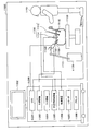
- FIG. 1 is a vertical cross-sectional view schematically illustrating a configuration example of a semiconductor device according to the first embodiment of the present disclosure.
- the semiconductor device 1 includes a substrate 100, an interlayer insulating film 110, a first inter-wiring insulating layer 120, a first wiring layer 130, a barrier layer 131, a cap layer 132, a sealing
- the semiconductor device includes a film 140, a second inter-wiring insulating layer 220, and interlayer insulating films 211 and 212.
- the gap 150 is formed by the flat surface of the second inter-wiring insulating layer 220 and the uneven shape of the first inter-wiring insulating layer 120 and the first wiring layer 130.
- the substrate 100 is a support on which the components of the semiconductor device 1 are provided. Specifically, as long as the substrate 100 has rigidity and is a plate-like member having a flat surface, a known substrate can be used, and various types of glass substrates, resin substrates, or semiconductor substrates can be used. It is possible to use.
- the substrate 100 may be a glass substrate formed of high strain point glass, soda glass, borosilicate glass, sapphire glass, quartz glass, or the like, and a resin such as polymethyl methacrylate, polyvinyl alcohol, polyimide, or polycarbonate. May be used, or a semiconductor substrate formed of Si, Ge, GaAs, GaN, SiC, or the like.
- the interlayer insulating film 110 is provided on the substrate 100 and separates the substrate 100 and the first wiring layer 130 from each other. Specifically, when the substrate 100 is a semiconductor substrate, the interlayer insulating film 110 is electrically insulated from various elements such as transistors formed on the substrate 100 and the first wiring layer 130 so as not to conduct. I do. Further, the interlayer insulating film 110 may be provided so that the components formed on the interlayer insulating film 110 are not affected by the surface shape of the substrate 100.
- the interlayer insulating film 110 may be made of a low dielectric constant material (a so-called low-k material) such as carbon-doped SiO 2 or porous silica, or an insulating material such as SiO 2 , SiCN, SiN, SiOC or SiOCN. .
- a low dielectric constant material such as carbon-doped SiO 2 or porous silica
- an insulating material such as SiO 2 , SiCN, SiN, SiOC or SiOCN.
- the interlayer insulating film 110 may be made of a low dielectric constant material (a so-called low-k material).
- the first inter-wiring insulating layer 120 is made of an insulating material and provided on the interlayer insulating film 110.
- the first inter-wiring insulating layer 120 forms a stacked structure of the semiconductor device 1 by supporting the second inter-wiring insulating layer 220. Further, a concave portion including the first wiring layer 130 therein is formed in the first inter-wiring insulating layer 120, and the first inter-wiring insulating layer 120 supports the second inter-wiring insulating layer 220 on the side wall of the concave portion. By doing so, a gap 150 is formed inside the concave portion.
- the first inter-wiring insulating layer 120 can form the void 150 having a relative dielectric constant of 1 around the first wiring layer 130, thereby reducing the inter-wiring capacitance of the first wiring layer 130. Can be.
- the first inter-wiring insulating layer 120 may be made of, for example, a low dielectric constant material (a so-called low-k material) such as carbon-doped SiO 2 or porous silica, or an insulating material such as SiO 2 or SiOC.
- a low dielectric constant material such as carbon-doped SiO 2 or porous silica
- an insulating material such as SiO 2 or SiOC.
- the first inter-wiring insulating layer 120 has a low dielectric constant such as a low dielectric constant material (a so-called low-k material), SiO 2, or SiOC.
- a low dielectric constant material a so-called low-k material
- SiO 2 SiOC
- it is made of an insulating material.
- the first wiring layer 130 is a wiring for electrically connecting each element included in the semiconductor device 1, and a plurality of first wiring layers 130 are provided so as to be embedded in the first inter-wiring insulating layer 120.
- the first wiring layer 130 is provided in an arbitrary layout inside the concave portion formed in the first inter-wiring insulating layer 120, and is provided from the bottom surface of the concave portion formed in the first inter-wiring insulating layer 120. It is provided so as to be convex.
- a void 150 formed by the concave portion of the first inter-wiring insulating layer 120 and the second inter-wiring insulating layer 220 is provided around the first wiring layer 130. Accordingly, the space between the wirings of the first wiring layer 130 can be defined as the gap 150 having the relative dielectric constant of 1, so that the capacitance between the wirings of the first wiring layer 130 can be reduced.
- the height of the first wiring layer 130 is equal to or less than the height of the first inter-wiring insulating layer 120. Therefore, a gap 150 may be provided between some of the first wiring layers 130 and the interlayer insulating film 212 provided on the surface of the second inter-wiring insulating layer 220. In such a case, the inter-wiring capacitance of the first wiring layer 130 can be further reduced. On the other hand, when the number of the first wiring layers 130 in contact with the interlayer insulating film 212 on the surface of the second inter-wiring insulating layer 220 is larger, the mechanical strength of the entire semiconductor device 1 can be further increased.
- the first wiring layer 130 is made of a conductive material, for example, copper (Cu), aluminum (Al), ruthenium (Ru), or cobalt (Co), or an alloy of these metals (eg, a Cu—Mn alloy or Al -Cu alloy or the like).
- a conductive material for example, copper (Cu), aluminum (Al), ruthenium (Ru), or cobalt (Co), or an alloy of these metals (eg, a Cu—Mn alloy or Al -Cu alloy or the like).
- the first wiring layer 130 is made of copper (Cu) or a copper alloy
- the first wiring layer 130 is formed so as to be embedded in the first inter-wiring insulating layer 120 by using a damascene method. It becomes easier.
- the barrier layer 131 is made of a metal having a high barrier property against atoms, and is provided on a surface other than the upper surface of the first wiring layer 130 (that is, the surface facing the second inter-wiring insulating layer). More specifically, the barrier layer 131 is provided on a surface where the first wiring layer 130 is in contact with the first inter-wiring insulating layer 120 in the manufacturing process, and the conductive material forming the first wiring layer 130 is formed of the first wiring layer. Diffusion into the inter-insulating layer 120 is prevented.
- the barrier layer 131 may be made of, for example, tantalum (Ta), titanium (Ti), manganese (Mn), ruthenium (Ru), or cobalt (Co), or a nitride or oxide of these metals.
- the barrier layer 131 is preferably made of a metal material that does not react with the materials forming the first wiring layer 130 and the first inter-wiring insulating layer 120 and has high adhesion to these materials.
- the cap layer 132 is made of a material having low permeability such as moisture or oxygen, and is provided on the first wiring layer 130 and the first inter-wiring insulating layer 120. Specifically, the cap layer 132 is provided on the upper surface of the first wiring layer 130 which is in contact with the second wiring insulating layer 220 via the interlayer insulating film 212 and on the upper surface of the side wall of the concave portion of the first wiring insulating layer 120. Can be That is, the cap layer 132 can be provided in a region where the first wiring layer 130 or the first inter-wiring insulating layer 120 and the second inter-wiring insulating layer 220 are in contact with each other via the interlayer insulating film 212. The cap layer 132 can prevent deterioration in characteristics, reliability, and adhesion due to oxidation of the first wiring layer 130 and the first inter-wiring insulating layer 120 by moisture, oxygen, or the like in a manufacturing process. .
- the cap layer 132 may be configured as a single-layer film or a laminated film of, for example, SiO 2 , SiC, SiCN, SiOC, SiON, AlN, or the like.
- the cap layer 132 may be made of the same material as the sealing film 140 described later, or may be made of a material different from the sealing film 140.
- the sealing film 140 is made of a material having low permeability such as moisture or oxygen, and is provided along the uneven shape of the first wiring layer 130 and the first inter-wiring insulating layer 120. Specifically, the sealing film 140 is provided on the inner surface of the concave portion of the first inter-wiring insulating layer 120, the surface of the first wiring layer 130 provided inside the concave portion, and the upper surface of the cap layer 132. The sealing film 140 is formed by oxidizing the first wiring layer 130 with moisture or oxygen remaining in the gap 150 to increase the electric resistance of the first wiring layer 130 or reduce the reliability of the first wiring layer 130. It can be prevented from lowering.
- the sealing film 140 may be configured as a single-layer film or a laminated film of, for example, SiO 2 , SiC, SiCN, SiOC, SiON, AlN, or the like.
- the gap 150 is provided in a space formed by the uneven shape of the first inter-wiring insulating layer 120 and the first wiring layer 130 and the flat surface of the second inter-wiring insulating layer 220.
- the inside of the space 150 may be, for example, a vacuum, may contain air, or may be filled with an inert gas such as nitrogen.
- the second inter-wiring insulating layer 220 is made of an insulating material, and is provided on the first inter-wiring insulating layer 120 via the cap layer 132, the sealing film 140, and the interlayer insulating film 212. Specifically, the second inter-wiring insulating layer 220 has a flat surface facing the concave portion of the first inter-wiring insulating layer 120, and is laminated on the first inter-wiring insulating layer 120 in a layered manner. Then, a gap 150 is formed between the first wiring insulating layer 120 and the concave portion.
- the second inter-wiring insulating layer 220 is provided so as to cover the recess by being provided flat on the upper surface of the side wall of the recess of the first inter-wiring insulating layer 120.
- the second inter-wiring insulating layer 220 can form the void 150 having a relative dielectric constant of 1 inside the concave portion of the first inter-wiring insulating layer 120.
- the surface of the second inter-wiring insulating layer 220 is flat may indicate that no recess, projection, or structure is provided on the corresponding surface of the second inter-wiring insulating layer 220.
- the second inter-wiring insulating layer 220 may be made of, for example, a low dielectric constant material (a so-called low-k material) such as carbon-doped SiO 2 or porous silica, or an insulating material such as SiO 2 or SiOC.
- a low dielectric constant material such as carbon-doped SiO 2 or porous silica
- an insulating material such as SiO 2 or SiOC.
- the second inter-wiring insulating layer 220 needs to have a low dielectric constant material (so-called low- k material), an insulating material having a low relative dielectric constant such as SiO 2 or SiOC.
- the second inter-wiring insulating layer 220 may be formed of the same material as the first inter-wiring insulating layer 120, or may be formed of a different material.
- the interlayer insulating films 211 and 212 are made of an insulating material, and are provided on both main surfaces of the second inter-wiring insulating layer 220, respectively.
- the interlayer insulating films 211 and 212 serve, for example, for improving the bonding strength between the second inter-wiring insulating layer 220 and another layer (for example, the sealing film 140), or for etching an upper or lower layer member. It has a stopper function, etc. In some cases, both or one of the interlayer insulating films 211 and 212 may not be provided.
- the interlayer insulating films 211 and 212 are made of, for example, a low dielectric constant material (a so-called low-k material) such as carbon-doped SiO 2 or porous silica, or an insulating material such as SiO 2 , SiCN, SiN, SiOC or SiOCN. Is also good.
- a low dielectric constant material such as carbon-doped SiO 2 or porous silica
- an insulating material such as SiO 2 , SiCN, SiN, SiOC or SiOCN. Is also good.
- the interlayer insulating films 211 and 212 can further reduce the parasitic capacitance of the semiconductor device 1.
- the interlayer insulating films 211 and 212 are formed of a silicon oxide film or a silicon nitride film (for example, SiO 2 , SiCN, SiN, SiOC, SiOCN, or the like), the interlayer insulating films 211 and 212 become the first inter-wiring insulation.
- the bonding strength between the layer 120 and the second inter-wiring insulating layer 220 can be further improved.
- the interlayer insulating films 211 and 212 may be formed of the same material or different materials. Further, the interlayer insulating films 211 and 212 may be formed of the same material as the interlayer insulating film 110, the second wiring insulating layer 220, or the first wiring insulating layer 120, or may be formed of a different material.
- the semiconductor device 1 stacks the uneven surface of the first inter-wiring insulating layer 120 and the flat surface of the second inter-wiring insulating layer 220 to form the first inter-wiring insulating layer 120.
- the inside of the concave portion can be the space 150. Therefore, in the semiconductor device 1, the first wiring layer 130 is formed in the void 150 provided in the concave portion of the first inter-wiring insulating layer 120. Therefore, in the semiconductor device 1, even when the first wiring layer 130 is formed in an arbitrary layout, the periphery of the first wiring layer 130 can be the void 150 having the relative dielectric constant of 1, so that the first wiring layer 130 can be formed. 130 can reduce the capacitance between wirings.
- the sealing film 140 can be formed on the first wiring layer 130 along the uneven shape of the first wiring layer 130. Therefore, the semiconductor device 1 prevents the first wiring layer 130 from being exposed to the gap 150, and prevents the first wiring layer 130 from being oxidized by oxygen or moisture that may be contained in the gap 150. Can be. According to this, the semiconductor device 1 prevents the electrical resistance of the first wiring layer 130 from increasing due to oxidation, and prevents the adhesiveness between the first wiring layer 130 and the first inter-wiring insulating layer 120 from decreasing. can do.
- FIG. 2 is a vertical cross-sectional view schematically showing a structural example of the semiconductor device 1A when the through via 160 is formed in the interlayer insulating film 110.
- the through via 160 is provided from below the first wiring layer 130 so as to reach the substrate 100 through the first inter-wiring insulating layer 120 and the interlayer insulating film 110. Thereby, the through via 160 can electrically connect the various elements provided on the substrate 100 and the first wiring layer 130.
- the through vias 160 may be appropriately provided based on various elements provided on the substrate 100 and the arrangement of the first wiring layer 130, and the number and arrangement of the through vias 160 are not particularly limited.
- the through via 160 is made of a conductive material, for example, copper (Cu), aluminum (Al), tungsten (W), tantalum (Ta), titanium (Ti), ruthenium (Ru), or cobalt (Co), or May be made of an alloy of the above metals.
- the through via 160 is not shown in the semiconductor device 1 shown in the drawings other than FIG. 2, but also in the semiconductor device 1 shown in these drawings, various elements provided on the substrate 100 and the first wiring layer 130 are electrically connected. It goes without saying that a through via 160 for connection may be provided.
- FIG. 3 is a schematic longitudinal sectional view for explaining the outline of the method for manufacturing the semiconductor device 1 according to the present embodiment.
- the semiconductor device 1 can be formed by bonding a plurality of substrates. Specifically, first, the substrate 100 on which the interlayer insulating film 110, the first inter-wiring insulating layer 120, the first wiring layer 130, the barrier layer 131, the cap layer 132, and the sealing film 140 are provided, and the second wiring An insulating layer 220 and a counter substrate 200 provided with interlayer insulating films 211 and 212 are prepared. Next, the semiconductor device 1 is formed by bonding the substrate 100 and the counter substrate 200 such that the first inter-wiring insulating layer 120 and the first wiring layer 130 and the second inter-wiring insulating layer 220 face each other. can do.
- the gap 150 can be formed on the bonding surface of the first wiring insulating layer 120 and the second wiring insulating layer 220.
- 4A to 4D are schematic longitudinal sectional views illustrating each step of the method for manufacturing the semiconductor device 1 according to the present embodiment.
- a first wiring embedded in the first inter-wiring insulating layer 120 by using a damascene method.
- a layer 130 is formed, and a cap layer 132 is formed.
- an interlayer insulating film 110 and a first inter-wiring insulating layer 120 are sequentially formed on the substrate 100 by using CVD (Chemical Vapor Deposition) or the like.
- the substrate 100 may be, for example, a silicon substrate.
- the interlayer insulating film 110 may be formed of, for example, SiO 2
- the first inter-wiring insulating layer 120 may be formed of a low dielectric constant material (a so-called low-k material).
- an opening is formed in the first inter-wiring insulating layer 120 using lithography or the like, a barrier layer 131 is formed inside the opening, and a conductive material such as copper (Cu) is filled so as to fill the opening.
- a conductive material such as copper (Cu) formed on the first inter-wiring insulating layer 120 other than the opening is removed by CMP (Chemical Mechanical Polish) or whole-surface etch back, and the first wiring is flattened.
- a layer 130 is formed.
- a cap layer 132 is formed on the planarized first inter-wiring insulating layer 120 and the first wiring layer 130.
- the barrier layer 131 may be formed of, for example, tantalum nitride (TaN) or titanium nitride (TiN). Further, the cap layer 132 may be formed of the above-described material.
- a patterned mask layer 151 is formed on the cap layer 132.
- a mask layer 151 is formed by lithography or the like so as to cover a region where the void 150 is not provided (that is, an opening is provided in the region where the void 150 is provided).
- the mask layer 151 may be, for example, a photoresist or the like, or may be a laminate of a hard mask such as an oxide film or a nitride film and a photoresist.
- the mask layer 151 may be provided in a region above the first inter-wiring insulating layer 120 or may be provided in a region above the first wiring layer 130. A region between the regions where the mask layer 151 is provided on the first inter-wiring insulating layer 120 is a region where a recess is formed in the first inter-wiring insulating layer 120. In a region where the mask layer 151 is provided on the first wiring layer 130, a wiring formed in the second inter-wiring insulating layer 220 in a later step and the first wiring layer 130 are electrically connected. Is formed.
- a recess 153 is formed in the first inter-wiring insulating layer 120.
- a sealing film 140 is formed on the first wiring layer 130 and the first inter-wiring insulating layer 120.
- the first inter-wiring insulating layer 120 and the first wiring layer 130 in a region that is not covered with the mask layer 151 are removed.
- a recess is formed in the one-wiring insulating layer 120.
- the first inter-wiring insulating layer 120 around the first wiring layer 130 is etched by performing etching such that the etching rate of the first inter-wiring insulating layer 120 is higher than the etching rate of the first wiring layer 130. It can be selectively removed.
- the depth of the recess formed in the first inter-wiring insulating layer 120 may be, for example, 30 nm to 400 nm. After that, a step of removing the whole or a part of the cap layer 132 may be performed.
- a sealing film 140 is conformally formed on the first wiring layer 130 and the first inter-wiring insulating layer 120 along the irregularities of the first wiring layer 130 and the first inter-wiring insulating layer 120.
- a conformal film formation can be performed by using, for example, CVD, ALD (Atomic Layer Deposition), p-CVD (plasma CVD), or the like.
- the opposite substrate 200 in which the interlayer insulating film 211, the second inter-wiring insulating layer 220, and the inter-layer insulating film 212 are laminated is bonded to the first wiring layer 130 and the first inter-wiring insulating layer 120. Thereby, the void 150 is formed around the first wiring layer 130.
- an interlayer insulating film 211, a second inter-wiring insulating layer 220, and an interlayer insulating film 212 are sequentially stacked on the counter substrate 200 using CVD or the like.
- the opposing substrate 200 may be, for example, a silicon substrate.
- the second inter-wiring insulating layer 220 may be formed of a low dielectric constant material (a so-called low-k material), and the interlayer insulating films 211 and 212 may be formed of, for example, SiO 2 .
- the substrate 100 and the counter substrate 200 are bonded to each other so that the first inter-wiring insulating layer 120 in which the concave portion is formed and the second inter-wiring insulating layer 220 having a flat main surface face each other.
- the gap 150 can be formed between the first wiring insulating layer 120 and the second wiring insulating layer 220.
- the bonding strength can be improved by activating the sealing film 140 and the interlayer insulating film 212, which are the bonding surfaces of the substrate 100 and the counter substrate 200.
- the step of bonding the substrate 100 and the counter substrate 200 may be performed in a vacuum. According to this, since the amount of oxygen or moisture remaining in the gap 150 can be reduced, the oxidation of the first wiring layer 130 can be further suppressed.
- a heat treatment step may be performed after the step of bonding the substrate 100 and the counter substrate 200. According to this, the bonding strength of the sealing film 140 and the interlayer insulating film 212, which are the bonding surfaces of the substrate 100 and the counter substrate 200, can be further improved.
- the semiconductor substrate 1 shown in FIG. 1 can be formed by peeling the counter substrate 200 from the interlayer insulating film 211. Specifically, the counter substrate 200 can be removed or separated from the interlayer insulating film 211 by using an entire surface etching, a back grinder, or the like.
- the second inter-wiring insulating layer 220 or the inter-layer insulating film 212 which is the bonding surface of the counter substrate 200, is flat and insulative, the alignment with the first wiring layer 130 is not considered.
- the opposing substrate 200 and the substrate 100 can be attached to each other. Therefore, according to such a manufacturing method, it is possible to manufacture the semiconductor device 1 with higher productivity.
- FIGS. 5A to 5C are longitudinal sectional views schematically showing examples of the structure of the semiconductor device according to the first to third modifications.
- a second wiring layer 230 is provided inside a second inter-wiring insulating layer 220, and the second wiring layer 230 and the first wiring layer 230 are provided by through vias 235.
- the difference from the semiconductor device 1 is that the wiring layer 130 is electrically connected.
- the semiconductor device 2A according to the first modification it is possible to further increase the number of layers of wiring.
- the second wiring layer 230 is provided so as to be buried in the second inter-wiring insulating layer 220 on the surface facing the surface of the first inter-wiring insulating layer 120 facing the recess.
- the second wiring layer 230 can be formed in any layout without particular limitation.
- the second wiring layer 230 is made of a conductive material, for example, copper (Cu), aluminum (Al), ruthenium (Ru), or cobalt (Co), or an alloy of these metals (eg, a Cu—Mn alloy or Al -Cu alloy or the like).
- the second wiring layer 230 can be easily embedded in the second inter-wiring insulating layer 220 by using a damascene method. It can be formed.
- the barrier layer 231 is made of a metal having a high barrier property against atoms, and is provided on the surface of the second wiring layer 230 where the second wiring layer 230 and the second inter-wiring insulating layer 220 are in contact.
- the cap layer 232 is made of a material having low permeability such as moisture or oxygen, and is provided on the second wiring layer 230 and the second inter-wiring insulating layer 220.
- the functions and materials of the barrier layer 231 and the cap layer 232 are substantially the same as those of the barrier layer 131 and the cap layer 132, and a description thereof will not be repeated.
- the through via 235 is provided to extend from below the second wiring layer 230 to the first wiring layer 130 through the second inter-wiring insulating layer 220, the interlayer insulating film 212, the sealing film 140, and the cap layer 132.
- the through via 235 can electrically connect the first wiring layer 130 and the second wiring layer 230.
- the through via 235 is provided in a region where the first wiring layer 130 is in contact with the second inter-wiring insulating layer 220 via the interlayer insulating film 212, the sealing film 140, and the cap layer 132.
- a semiconductor device 2B according to a second modified example further includes a first inter-wiring insulating layer 120 in which a first wiring layer 130 and a void 150 are formed inside a concave portion, which is further repeatedly formed. Is different from the semiconductor device 2A. According to the semiconductor device 2B according to the second modified example, it is possible to reduce the inter-wiring capacitance of each of the wirings formed in a plurality of layers.
- a third inter-wiring insulating layer 320 is provided on the first inter-wiring insulating layer 120 with an inter-layer insulating film 312 interposed therebetween.
- a void 150 is formed by the concave portion of the interlayer insulating layer 120.
- the third inter-wiring insulating layer 320 is provided with a third wiring layer 330, a barrier layer 331, a cap layer 332, and a sealing film 340. Is formed.
- the first wiring layer 130 and the third wiring layer 330 have the same layout, but the first wiring layer 130 and the third wiring layer 330 may have independent layouts. Good.
- the third wiring layer 330 is formed by a through via 325 provided below the third wiring layer 330 through the third inter-wiring insulating layer 320, the interlayer insulating film 312, the sealing film 140, and the cap layer 132.
- a through via that is electrically connected to the wiring layer 130 and is provided from below the second wiring layer 230 to penetrate the second inter-wiring insulating layer 220, the interlayer insulating film 212, the sealing film 340, and the cap layer 332.
- By 225 it is electrically connected to the second wiring layer 230. According to this, it is possible to electrically connect the first wiring layer 130, the third wiring layer 330, and the second wiring layer 230 in which the gaps 150 and 350 are provided between the wirings.
- the 1st wiring wiring insulating layer 120, the 1st wiring layer 130, the barrier layer 131, the cap layer 132, the sealing film 140, and the through via 235 are substantially the same as those of the first embodiment.
- a semiconductor device 2C according to a third modification includes a fifth inter-wiring insulating layer 520, a fifth wiring layer 530, a fourth inter-wiring insulating layer 420, a fourth wiring layer 430, and the like.
- the semiconductor device 2B is different from the semiconductor device 2B in that a semiconductor substrate 500 on which a circuit having a predetermined function is formed is further attached.
- the semiconductor device 2C according to the third modification it is possible to reduce the capacitance between wirings in a stacked semiconductor device in which substrates on which circuits having different functions are formed are stacked.
- the substrate 100 may be provided with a pixel circuit in which a plurality of pixels are arranged
- the semiconductor substrate 500 may be provided with a logic circuit which processes information of a pixel signal photoelectrically converted in a pixel portion.
- the semiconductor substrate 500 may be formed of Si, Ge, GaAs, GaN, SiC, or the like.
- the stacked structure of the semiconductor substrate 500 may be any stacked structure.
- a fifth inter-wiring insulating layer 520 is provided over the semiconductor substrate 500 with an inter-layer insulating film 511 interposed therebetween, and a fifth wiring layer 530 is provided so as to be embedded in the fifth inter-wiring insulating layer 520.
- a fourth wiring insulating layer 410 is provided on the fifth wiring layer 530 and the fifth wiring insulating layer 520 via a cap layer 513, and the fourth wiring layer 430 is embedded in the fourth wiring insulating layer 410. May be provided.
- barrier layers 531 and 431 are provided on the contact surface between the fifth wiring layer 530 and the fifth inter-wiring insulating layer 520 and on the contact surface between the fourth wiring layer 430 and the fourth inter-wiring insulating layer 420, respectively. It may be.
- the fourth wiring layer 430 is provided so as to be exposed on the surface of the fourth inter-wiring insulating layer 420, and similarly, the second wiring layer 230 is provided so as to be exposed on the surface of the second inter-wiring insulating layer 220. Is provided.
- the second wiring layer 230 and the fourth wiring layer 430 can form an electrical connection by bonding the conductive materials (for example, copper or copper alloy) exposed to each other by heat treatment or the like.
- the second wiring layer 230 and the fourth wiring layer 430 can be electrically connected without forming a through via or the like between the second wiring layer 230 and the fourth wiring layer 430.
- the manufacturing process of the semiconductor device 2C can be further simplified.
- the fourth wiring insulating layer 420 and the fifth wiring insulating layer 520 are substantially the same as the first wiring insulating layer 120, and the fourth wiring layer 430 and the fifth wiring layer 530 are the same as the first wiring layer 130.
- the interlayer insulating film 511 is substantially the same as the interlayer insulating film 312
- the cap layer 512 is substantially the same as the cap layer 132
- the barrier layers 431 and 531 are Since it is substantially the same as 131, the description here is omitted.
- FIG. 6A is a longitudinal sectional view schematically illustrating a first example of the structure of the solid-state imaging device according to the present embodiment.
- FIG. 6B is an explanatory diagram schematically illustrating a pixel circuit of the solid-state imaging device according to the present embodiment.
- 7A and 7B are plan cross-sectional views schematically showing a plane arrangement of a first structural example of the solid-state imaging device according to the present embodiment.
- an interlayer insulating film 710, 737, 757 and an inter-wiring insulating layer 720, 730, 740, 750, 760 are stacked on a semiconductor substrate 700 such as a silicon substrate. It is composed of Wiring layers 723, 733, 743, and 753 formed of copper, a copper alloy, or the like are provided on the interwiring insulating layers 720, 730, 740, and 750, respectively.
- the wiring layers 723, 733, 743, and 753 are electrically connected, for example, by through vias 732, 742, and 752 that pass through the inter-wiring insulating layers 730, 740, and 750, respectively.
- barrier layers 721, 731, 741, and 751 may be provided on contact surfaces between the wiring layers 723, 733, 743, and 753 and the inter-wiring insulating layers 720, 730, 740, and 750.
- 753 may be provided with cap layers 736, 756.
- a photodiode (not shown), a power supply (not shown), a floating diffusion 711, and the like are formed on the semiconductor substrate 700.
- a transfer transistor, a reset transistor, an amplification transistor, a selection transistor, and the like are formed on the semiconductor substrate 700.
- a plurality of transistors 712 are formed. That is, the pixel portion of the solid-state imaging device 10 is provided on the semiconductor substrate 700.
- the pixel unit of the solid-state imaging device 10 may include, for example, a pixel circuit illustrated in FIG. 6B.
- the solid-state imaging device 10 includes an imaging unit 13 (a so-called pixel unit) in which a plurality of pixels 12 are two-dimensionally arranged with regularity, It is configured to include peripheral circuits arranged in the periphery, that is, a vertical drive unit 14, a horizontal transfer unit 15, and an output unit 16.
- Each of the pixels 12 may include one photodiode PD, a floating diffusion FD, and four transistors of a transfer transistor Tr1, a reset transistor Tr2, an amplification transistor Tr3, and a selection transistor Tr4.
- the floating diffusion FD and the four transistors of the transfer transistor Tr1, the reset transistor Tr2, the amplification transistor Tr3, and the selection transistor Tr4 do not necessarily need to be provided on the same substrate as the photodiode PD.
- all or part of the floating diffusion FD and the four transistors may be provided on a substrate different from the substrate provided with the photodiode PD.
- the photodiode PD is a photoelectric conversion element that generates signal charges by photoelectrically converting incident light.
- the transfer transistor Tr1 is a transistor that reads out signal charges accumulated in the photodiode PD to a floating diffusion FD described later.
- the floating diffusion FD is a region provided between the transfer transistor Tr1 and the reset transistor Tr2 for storing signal charges.
- the reset transistor Tr2 is a transistor for setting the potential of the floating diffusion FD to a specified value.
- the amplifying transistor Tr3 is a transistor for electrically amplifying the signal charges read to the floating diffusion FD.
- the selection transistor Tr ⁇ b> 4 is a transistor for reading out the amplified pixel signal to the vertical signal line 18 by selecting one row of the pixel unit of the solid-state imaging device 10. Although not shown, the selection transistor may not be provided depending on the configuration of the pixel 12.
- the source of the transfer transistor Tr1 is connected to the photodiode PD, and the drain of the transfer transistor Tr1 is connected to the source of the reset transistor Tr2.
- the floating diffusion FD (corresponding to the drain region of the transfer transistor Tr1 and the source region of the reset transistor Tr2) between the transfer transistor Tr1 and the reset transistor Tr2 is connected to the gate of the amplification transistor Tr3.
- the source of the amplification transistor Tr3 is connected to the drain of the selection transistor Tr4.
- the drain of the reset transistor Tr2 and the drain of the amplification transistor Tr3 are connected to a power supply. Further, the source of the selection transistor Tr4 is connected to the vertical signal line 18.
- the amplification transistor Tr3 electrically amplifies the signal charge in response to the charge being applied to the gate.
- only the pixel to be read is turned on from the time of resetting the floating diffusion FD, so that the selection transistor Tr4 reads out the image signal subjected to the charge-voltage conversion by the amplification transistor Tr3 to the vertical signal line 18.
- the vertical drive unit 14 supplies a row reset signal ⁇ RST commonly applied to the gates of the reset transistors Tr2 of the pixels arranged in one row.
- the vertical drive unit 14 also supplies a row transfer signal ⁇ TRG that is commonly applied to the gates of the transfer transistors Tr1 of the pixels in one row.
- the vertical drive unit 14 supplies a row selection signal ⁇ SEL that is also commonly applied to the gates of the selection transistors Tr4 in one row.
- the horizontal transfer unit 15 includes, for example, an analog / digital converter 19 connected to the vertical signal line 18 of each column, a column selection circuit SW (for example, a switch), and a horizontal transfer line 20 (for example, the same number as the number of data bit lines). (A bus wiring composed of wiring).
- the output unit 16 includes, for example, a signal processing circuit 21 that processes an output from the horizontal transfer line 20, and an output buffer 22.
- the signals of the pixels 12 in each row are converted from analog to digital by each of the analog / digital converters 19, and read out to the horizontal transfer line 20 through the sequentially selected column selection circuit SW.
- the data is sequentially transferred horizontally.
- the image data read to the horizontal transfer line 20 is output from the output buffer 22 through the signal processing circuit 21.
- the wiring layer 723 is provided inside the concave portion of the inter-wiring insulating layer 720, and the wiring layer 723 is surrounded by the concave portion of the inter-wiring insulating layer 720 and the interlayer insulating film 737.
- a void 725 to be formed is provided.
- the wiring layer 743 is provided inside the concave portion of the inter-wiring insulating layer 740, and a void 745 formed by the concave portion of the inter-wiring insulating layer 740 and the interlayer insulating film 757 is provided around the wiring layer 743. . According to this, in the solid-state imaging device 10, it is possible to further reduce the capacitance between wirings of the wiring layers 723 and 743.
- the wiring layers 723 and 743 in which the capacitance between wirings is reduced may be, for example, FD (floating diffusion) wiring or vertical signal lines. Such a configuration will be described with reference to FIGS. 7A and 7B.
- the wiring layer 743 is a vertical signal line, and may be a wiring extending and connecting each of the pixels arranged in a matrix in one direction (for example, the column direction).
- the void 745 may be provided in a region between the through vias 752 connected to the wiring layer 743.
- the solid-state imaging device 10 can increase the transmission speed of the analog signal by reducing the capacitance between wirings of the wiring layer 743 by the gap 745.
- the wiring layer 723 is an FD wiring, and may be a wiring of a path through which signal charges photoelectrically converted by the photodiode are transmitted to the plurality of transistors 712.
- the void 725 may be provided in a region excluding the periphery of the through via 732 connected to the wiring layer 723.
- the solid-state imaging device 10 can further improve the conversion efficiency when converting signal charges into pixel signals by reducing the capacitance between wirings of the wiring layer 723 by the gap 725.
- the wiring layer 723 is provided with a complicated layout according to the layout of the photodiode and various transistors of each pixel. Therefore, by using the technology according to the present disclosure that can form a gap between the wirings even in a wiring having an arbitrary layout, the gap 725 can be more reliably provided between the wirings of the wiring layer 723. .
- FIG. 8 is a longitudinal sectional view schematically showing a second example of the structure of the solid-state imaging device according to the present embodiment.
- a PD (photodiode) 20019 receives incident light 20001 incident from the back surface (the upper surface in the figure) of the semiconductor substrate 20018.
- a planarizing film 2001, a CF (color filter) 2001, and a microlens 20011 are provided above the PD 20019.
- the incident light 20001 incident through each part sequentially is received by the light receiving surface 20017 to perform photoelectric conversion. Is done.
- an n-type semiconductor region 20020 is formed as a charge storage region for storing charges (electrons).
- the n-type semiconductor region 20020 is provided inside the p-type semiconductor region 20061 and 20041 of the semiconductor substrate 20018.
- a p-type semiconductor region 20041 having a higher impurity concentration than the back surface (upper surface) is provided on the surface (lower surface) side of the semiconductor substrate 20018 of the n-type semiconductor region 20020.
- the PD 20019 has a HAD (Hole-Accumulation @Diode) structure, and the p-type semiconductor regions 200616 and 20041 generate dark current at each interface between the upper surface side and the lower surface side of the n-type semiconductor region 20082. Is formed so as to suppress
- a pixel separating portion 20030 for electrically separating a plurality of pixels 20010 is provided inside the semiconductor substrate 20018, and a PD 20019 is provided in a region partitioned by the pixel separating portion 20030.
- the pixel separating unit 20030 is formed in a lattice shape so as to be interposed between a plurality of pixels 20010, for example.
- the PD 20019 is formed in a region partitioned by the pixel separating section 20030.
- each PD 20019 the anode is grounded, and the signal charges (for example, electrons) accumulated in the PD 20019 in the solid-state imaging device are read out via a transfer Tr (MOS) FET) (not shown) or the like, and converted into an electric signal. Output to VSL (vertical signal line) not shown.
- Tr transfer Tr
- VSL vertical signal line
- the wiring layer 20050 is provided on the surface (lower surface) of the semiconductor substrate 20018 opposite to the rear surface (upper surface) on which the light-shielding film 20004, the CF2002, the microlens 20011, and the like are provided.
- the wiring layer 20050 includes the wiring 20051 and the insulating layer 20052, and is formed in the insulating layer 20052 so that the wiring 20051 is electrically connected to each element.
- the wiring layer 20050 is a so-called multilayer wiring layer, and is formed by alternately laminating an interlayer insulating film constituting the insulating layer 20052 and the wiring 20051 a plurality of times.
- a wiring to a Tr for reading charges from the PD 20019 such as a transfer Tr, or each wiring such as a VSL is stacked via an insulating layer 20052.
- a support substrate 20061 is provided on the surface of the wiring layer 20050 opposite to the side on which the PD 20019 is provided.
- a substrate made of a silicon semiconductor with a thickness of several hundred ⁇ m is provided as the support substrate 20061.
- the light-shielding film 20004 is provided on the back surface (the upper surface in the drawing) of the semiconductor substrate 20018.
- the light-shielding film 20004 is configured to shield a part of the incident light 20001 from above the semiconductor substrate 20018 toward the back surface of the semiconductor substrate 20018.
- the light-shielding film 20004 is provided above the pixel separating portion 20030 provided inside the semiconductor substrate 20018.
- the light-shielding film 20004 is provided so as to project in a convex shape on the back surface (upper surface) of the semiconductor substrate 20018 via an insulating film 20005 such as a silicon oxide film.
- the light shielding film 20004 is not provided but is open so that the incident light 20001 enters the PD 20009.
- the planar shape of the light shielding film 20144 is a lattice shape, and an opening through which the incident light 20001 passes to the light receiving surface 20017 is formed.
- the light-blocking film 20004 is formed of a light-blocking material that blocks light.
- a light-shielding film 20004 is formed by sequentially stacking a titanium (Ti) film and a tungsten (W) film.
- the light-shielding film 20004 can be formed by, for example, sequentially stacking a titanium nitride (TiN) film and a tungsten (W) film.
- the light-shielding film 20004 is covered with the flattening film 20013.
- the planarizing film 20013 is formed using an insulating material that transmits light.
- the pixel separation unit 20030 has a groove 20031, a fixed charge film 20032, and an insulating film 20033.
- the fixed charge film 20032 is formed on the back surface (upper surface) of the semiconductor substrate 20018 so as to cover the groove 20031 that partitions the plurality of pixels 20010.
- the fixed charge film 20032 is provided so as to cover the inside surface of the groove 20031 formed on the back surface (upper surface) side of the semiconductor substrate 20018 with a constant thickness.
- An insulating film 20033 is provided (filled) so as to fill the inside of the groove 20031 covered with the fixed charge film 20032.
- the fixed charge film 20032 is formed using a high dielectric substance having negative fixed charges so that a positive charge (hole) accumulation region is formed at the interface with the semiconductor substrate 20018 and generation of dark current is suppressed. It is formed. Since the fixed charge film 20032 is formed to have a negative fixed charge, an electric field is applied to the interface with the semiconductor substrate 20018 by the negative fixed charge, so that a positive charge (hole) accumulation region is formed.
- the fixed charge film 20032 can be formed of, for example, a hafnium oxide film (HfO 2 film).
- the fixed charge film 20032 can be formed to include at least one of oxides such as hafnium, zirconium, aluminum, tantalum, titanium, magnesium, yttrium, and a lanthanoid element.
- the technology according to the present disclosure can be applied to the wiring layer 20050 of the solid-state imaging device as described above.
- FIG. 9 is a longitudinal sectional view schematically showing a third example of the structure of the solid-state imaging device according to the present embodiment.
- FIG. 9 shows a configuration example of a stacked solid-state imaging device.
- the solid-state imaging device 23020 includes two dies, a sensor die 23021 and a logic die 23024, which are stacked and electrically connected to each other to form one semiconductor chip.
- PDs photodiodes
- FDs floating diffusions
- Trs MOS FETs
- Trs Trs serving as control circuits
- the control circuit can be configured in the logic die 23024 instead of the sensor die 23021.
- the sensor die 23021 may be provided with a pixel circuit including a plurality of Trs and the FD as described in the first structure example.
- Trs forming a logic circuit are formed. Furthermore, a wiring layer 23161 having a plurality of layers, in this example, three layers of wiring 23170, is formed on the logic die 23024. In the logic die 23024, a connection hole 23171 having an insulating film 23172 formed on the inner wall surface is formed, and a connection conductor 23173 connected to the wiring 23170 and the like is embedded in the connection hole 23171.
- the sensor die 23021 and the logic die 23024 are bonded together so that the wiring layers 23101 and 23161 face each other, whereby a stacked solid-state imaging device 23020 in which the sensor die 23021 and the logic die 23024 are stacked is configured.
- the solid-state imaging device 23020 is configured by overlapping the sensor die 23021 and the logic die 23024 so that the wires 23110 and 23170 are in direct contact, heating while applying a required load, and directly bonding the wires 23110 and 23170. . Accordingly, the sensor die 23021 and the logic die 23024 are electrically connected via the wiring layer 23101 and the wiring layer 23161.
- the technology according to the present disclosure can be applied to the wiring layers 23101 and 23161 of the solid-state imaging device 23020 described above.
- FIG. 10 is a longitudinal sectional view schematically showing a fourth example of the structure of the solid-state imaging device according to the present embodiment.
- FIG. 10 shows a configuration example of a stacked solid-state imaging device.
- the solid-state imaging device 23401 has a three-layer structure in which a sensor die 23411, a logic die 23412, and a memory die 23413 are stacked, and is electrically connected to each other to form one semiconductor chip. Have been.
- the logic die 23412 and the memory die 23413 are stacked under the sensor die 23411 in that order. 23411.
- Trs forming a logic circuit are formed on the logic die 23412.
- the memory die 23413 has, for example, a memory circuit that stores data temporarily required in signal processing performed by the logic die 23412.
- the PD serving as a photoelectric conversion unit of the pixel and the source / drain region of the pixel Tr are formed in the sensor die 23411.
- the sensor die 23411 may be provided with a pixel circuit including a plurality of Trs and the FD as described in the first structure example.
- a gate electrode is formed around the PD via a gate insulating film, and a pixel Tr23421 and a pixel Tr23422 are formed by the gate electrode and a pair of source / drain regions.
- a pixel Tr 23421 adjacent to the PD is a transfer Tr, and one of a pair of source / drain regions constituting the pixel Tr 23421 is an FD.
- An interlayer insulating film is formed in the sensor die 23411, and a connection hole is formed in the interlayer insulating film.
- a connection hole is formed in the connection hole.
- a wiring layer 23433 having a plurality of layers of wiring 23432 connected to each connection conductor 23431 is formed on the sensor die 23411.
- an aluminum pad 23434 serving as an electrode for external connection is formed on the lowermost layer of the wiring layer 23433 of the sensor die 23411. That is, in the sensor die 23411, the aluminum pad 23434 is formed at a position closer to the bonding surface 23440 with the logic die 23412 than the wiring 23432.
- the aluminum pad 23434 is used as one end of a wiring related to input / output of a signal with the outside.
- a contact 23441 used for electrical connection with the logic die 23412 is formed on the sensor die 23411.
- the contact 23441 is connected to the contact 23451 of the logic die 23412 and also to the aluminum pad 23442 of the sensor die 23411.
- a pad hole 23443 is formed in the sensor die 23411 so as to reach the aluminum pad 23442 from the back side (upper side) of the sensor die 23411.
- the technology according to the present disclosure can be applied to the wiring layer 23433 of the solid-state imaging device 23401 as described above.
- the technology (the present technology) according to the present disclosure can be applied to various products.
- the technology according to the present disclosure may be applied to an endoscopic surgery system.
- FIG. 11 is a diagram illustrating an example of a schematic configuration of an endoscopic surgery system to which the technology (the present technology) according to the present disclosure may be applied.
- FIG. 11 shows a state in which an operator (doctor) 11131 is performing an operation on a patient 11132 on a patient bed 11133 using the endoscopic surgery system 11000.
- the endoscopic surgery system 11000 includes an endoscope 11100, other surgical tools 11110 such as an insufflation tube 11111 and an energy treatment tool 11112, and a support arm device 11120 that supports the endoscope 11100.
- a cart 11200 on which various devices for endoscopic surgery are mounted.
- the endoscope 11100 includes a lens barrel 11101 having a region of a predetermined length from the distal end inserted into the body cavity of the patient 11132, and a camera head 11102 connected to the proximal end of the lens barrel 11101.
- the endoscope 11100 that is configured as a so-called rigid endoscope having a hard lens barrel 11101 is illustrated.
- the endoscope 11100 may be configured as a so-called flexible endoscope that has a soft lens barrel. Good.
- An opening in which the objective lens is fitted is provided at the tip of the lens barrel 11101.
- a light source device 11203 is connected to the endoscope 11100, and light generated by the light source device 11203 is guided to a distal end of the lens barrel by a light guide extending inside the lens barrel 11101, and an objective is provided. The light is radiated toward the observation target in the body cavity of the patient 11132 via the lens.
- the endoscope 11100 may be a direct view, a perspective view, or a side view.
- An optical system and an image sensor are provided inside the camera head 11102, and the reflected light (observation light) from the observation target is focused on the image sensor by the optical system.
- the observation light is photoelectrically converted by the imaging element, and an electric signal corresponding to the observation light, that is, an image signal corresponding to the observation image is generated.
- the image signal is transmitted as raw data to a camera control unit (CCU: ⁇ Camera ⁇ Control ⁇ Unit) 11201.
- the $ CCU 11201 is configured by a CPU (Central Processing Unit), a GPU (Graphics Processing Unit), and the like, and controls the operations of the endoscope 11100 and the display device 11202 overall. Further, the CCU 11201 receives an image signal from the camera head 11102, and performs various image processing on the image signal for displaying an image based on the image signal, such as a development process (demosaicing process).
- a development process demosaicing process
- the display device 11202 displays an image based on an image signal on which image processing has been performed by the CCU 11201 under the control of the CCU 11201.
- the light source device 11203 includes a light source such as an LED (light emitting diode), for example, and supplies the endoscope 11100 with irradiation light at the time of imaging an operation part or the like.
- a light source such as an LED (light emitting diode)
- LED light emitting diode
- the input device 11204 is an input interface to the endoscopic surgery system 11000.
- the user can input various information and input instructions to the endoscopic surgery system 11000 via the input device 11204.
- the user inputs an instruction or the like to change imaging conditions (type of irradiation light, magnification, focal length, and the like) by the endoscope 11100.
- the treatment instrument control device 11205 controls the driving of the energy treatment instrument 11112 for cauterizing, incising a tissue, sealing a blood vessel, and the like.
- the insufflation device 11206 is used to inflate the body cavity of the patient 11132 for the purpose of securing the visual field by the endoscope 11100 and securing the working space of the operator.
- the recorder 11207 is a device that can record various types of information related to surgery.
- the printer 11208 is a device that can print various types of information on surgery in various formats such as text, images, and graphs.
- the light source device 11203 that supplies the endoscope 11100 with irradiation light at the time of imaging the operation site can be configured by a white light source configured by, for example, an LED, a laser light source, or a combination thereof.
- a white light source configured by a combination of the RGB laser light sources
- the output intensity and output timing of each color (each wavelength) can be controlled with high accuracy. It can be carried out.
- laser light from each of the RGB laser light sources is irradiated to the observation target in a time-division manner, and the driving of the image pickup device of the camera head 11102 is controlled in synchronization with the irradiation timing, so that each of the RGB laser light sources is controlled. It is also possible to capture the image obtained in a time-division manner. According to this method, a color image can be obtained without providing a color filter in the image sensor.
- the driving of the light source device 11203 may be controlled so as to change the intensity of the output light every predetermined time.
- the driving of the image pickup device of the camera head 11102 in synchronization with the timing of the change of the light intensity, an image is acquired in a time-division manner, and the image is synthesized, so that a high dynamic image without so-called black-out or over-exposure is obtained. An image of the range can be generated.
- the light source device 11203 may be configured to be able to supply light in a predetermined wavelength band corresponding to special light observation.
- special light observation for example, by utilizing the wavelength dependence of light absorption in body tissue, by irradiating light of a narrower band compared to irradiation light (ie, white light) at the time of normal observation, the surface of the mucous membrane is exposed.
- a so-called narrow-band light observation (Narrow Band Imaging) for photographing a predetermined tissue such as a blood vessel with high contrast is performed.
- a fluorescence observation for obtaining an image by fluorescence generated by irradiating the excitation light may be performed.
- the body tissue is irradiated with excitation light to observe the fluorescence from the body tissue (autofluorescence observation), or a reagent such as indocyanine green (ICG) is locally injected into the body tissue and Irradiation with excitation light corresponding to the fluorescence wavelength of the reagent can be performed to obtain a fluorescence image.
- the light source device 11203 can be configured to be able to supply narrowband light and / or excitation light corresponding to such special light observation.
- FIG. 12 is a block diagram showing an example of a functional configuration of the camera head 11102 and the CCU 11201 shown in FIG.
- the camera head 11102 includes a lens unit 11401, an imaging unit 11402, a driving unit 11403, a communication unit 11404, and a camera head control unit 11405.
- the CCU 11201 includes a communication unit 11411, an image processing unit 11412, and a control unit 11413.
- the camera head 11102 and the CCU 11201 are communicably connected to each other by a transmission cable 11400.
- the lens unit 11401 is an optical system provided at a connection with the lens barrel 11101. Observation light taken in from the tip of the lens barrel 11101 is guided to the camera head 11102, and enters the lens unit 11401.
- the lens unit 11401 is configured by combining a plurality of lenses including a zoom lens and a focus lens.
- the number of imaging elements constituting the imaging unit 11402 may be one (so-called single-panel type) or plural (so-called multi-panel type).
- image signals corresponding to RGB may be generated by the imaging elements, and a color image may be obtained by combining the image signals.
- the imaging unit 11402 may be configured to include a pair of imaging elements for acquiring right-eye and left-eye image signals corresponding to 3D (dimensional) display. By performing the 3D display, the operator 11131 can more accurately grasp the depth of the living tissue in the operative part.
- a plurality of lens units 11401 may be provided for each imaging device.
- the imaging unit 11402 does not necessarily need to be provided in the camera head 11102.
- the imaging unit 11402 may be provided inside the lens barrel 11101 immediately after the objective lens.
- the driving unit 11403 is configured by an actuator, and moves the zoom lens and the focus lens of the lens unit 11401 by a predetermined distance along the optical axis under the control of the camera head control unit 11405.
- the magnification and the focus of the image captured by the imaging unit 11402 can be appropriately adjusted.
- the communication unit 11404 is configured by a communication device for transmitting and receiving various information to and from the CCU 11201.
- the communication unit 11404 transmits the image signal obtained from the imaging unit 11402 as RAW data to the CCU 11201 via the transmission cable 11400.
- the communication unit 11404 receives a control signal for controlling the driving of the camera head 11102 from the CCU 11201 and supplies the control signal to the camera head control unit 11405.
- the control signal includes, for example, information indicating the frame rate of the captured image, information indicating the exposure value at the time of imaging, and / or information indicating the magnification and focus of the captured image. Contains information about the condition.
- imaging conditions such as the frame rate, the exposure value, the magnification, and the focus may be appropriately designated by the user, or may be automatically set by the control unit 11413 of the CCU 11201 based on the acquired image signal. Good.
- a so-called AE (Auto Exposure) function, an AF (Auto Focus) function, and an AWB (Auto White Balance) function are mounted on the endoscope 11100.
- the camera head controller 11405 controls driving of the camera head 11102 based on a control signal from the CCU 11201 received via the communication unit 11404.
- the communication unit 11411 is configured by a communication device for transmitting and receiving various information to and from the camera head 11102.
- the communication unit 11411 receives an image signal transmitted from the camera head 11102 via the transmission cable 11400.
- the communication unit 11411 transmits a control signal for controlling driving of the camera head 11102 to the camera head 11102.
- the image signal and the control signal can be transmitted by electric communication, optical communication, or the like.
- the image processing unit 11412 performs various types of image processing on an image signal that is RAW data transmitted from the camera head 11102.
- the control unit 11413 performs various kinds of control relating to imaging of the operation section and the like by the endoscope 11100 and display of a captured image obtained by imaging the operation section and the like. For example, the control unit 11413 generates a control signal for controlling driving of the camera head 11102.
- control unit 11413 causes the display device 11202 to display a captured image showing the operative part or the like based on the image signal on which the image processing is performed by the image processing unit 11412.
- the control unit 11413 may recognize various objects in the captured image using various image recognition techniques. For example, the control unit 11413 detects a surgical tool such as forceps, a specific living body site, a bleeding, a mist at the time of using the energy treatment tool 11112, and the like by detecting the shape and color of the edge of the object included in the captured image. Can be recognized.
- the control unit 11413 may use the recognition result to superimpose and display various types of surgery support information on the image of the operative site. By superimposing the operation support information and presenting it to the operator 11131, the burden on the operator 11131 can be reduced, and the operator 11131 can surely proceed with the operation.
- the transmission cable 11400 connecting the camera head 11102 and the CCU 11201 is an electric signal cable corresponding to electric signal communication, an optical fiber corresponding to optical communication, or a composite cable thereof.
- the communication is performed by wire using the transmission cable 11400, but the communication between the camera head 11102 and the CCU 11201 may be performed wirelessly.
- the technology according to the present disclosure can be applied to, for example, the imaging unit 11402 of the camera head 11102 among the configurations described above.
- the solid-state imaging device 10 illustrated in FIG. 6A or the like can be applied to the imaging unit 10402.
- the technology according to the present disclosure may be applied to, for example, a microscopic surgery system and the like.
- the technology according to the present disclosure is realized as a device mounted on any type of moving object such as an automobile, an electric vehicle, a hybrid electric vehicle, a motorcycle, a bicycle, a personal mobility, an airplane, a drone, a ship, and a robot. May be.
- FIG. 13 is a block diagram illustrating a schematic configuration example of a vehicle control system that is an example of a mobile object control system to which the technology according to the present disclosure can be applied.
- Vehicle control system 12000 includes a plurality of electronic control units connected via communication network 12001.
- the vehicle control system 12000 includes a drive system control unit 12010, a body system control unit 12020, an outside information detection unit 12030, an inside information detection unit 12040, and an integrated control unit 12050.
- a microcomputer 12051, an audio / video output unit 12052, and a vehicle-mounted network I / F (Interface) 12053 are illustrated.
- the drive system control unit 12010 controls the operation of the device related to the drive system of the vehicle according to various programs.
- the drive system control unit 12010 includes a drive force generation device for generating a drive force of the vehicle such as an internal combustion engine or a drive motor, a drive force transmission mechanism for transmitting the drive force to wheels, and a steering angle of the vehicle. It functions as a control device such as a steering mechanism for adjusting and a braking device for generating a braking force of the vehicle.
- the body control unit 12020 controls the operation of various devices mounted on the vehicle body according to various programs.
- the body control unit 12020 functions as a keyless entry system, a smart key system, a power window device, or a control device for various lamps such as a head lamp, a back lamp, a brake lamp, a blinker, a fog lamp, and the like.
- a radio wave or various switch signals transmitted from a portable device that substitutes for a key may be input to the body control unit 12020.
- the body control unit 12020 receives the input of these radio waves or signals, and controls a door lock device, a power window device, a lamp, and the like of the vehicle.
- Out-of-vehicle information detection unit 12030 detects information outside the vehicle equipped with vehicle control system 12000.
- an imaging unit 12031 is connected to the outside-of-vehicle information detection unit 12030.
- the out-of-vehicle information detection unit 12030 causes the imaging unit 12031 to capture an image outside the vehicle, and receives the captured image.
- the out-of-vehicle information detection unit 12030 may perform an object detection process or a distance detection process of a person, a vehicle, an obstacle, a sign, a character on a road surface, or the like based on the received image.
- the imaging unit 12031 is an optical sensor that receives light and outputs an electric signal according to the amount of received light.
- the imaging unit 12031 can output the electric signal as an image or can output the electric signal as distance measurement information.
- the light received by the imaging unit 12031 may be visible light or non-visible light such as infrared light.
- the in-vehicle information detection unit 12040 detects information in the vehicle.
- the in-vehicle information detection unit 12040 is connected to, for example, a driver status detection unit 12041 that detects the status of the driver.
- the driver state detection unit 12041 includes, for example, a camera that captures an image of the driver, and the in-vehicle information detection unit 12040 determines the degree of fatigue or concentration of the driver based on the detection information input from the driver state detection unit 12041. The calculation may be performed, or it may be determined whether the driver has fallen asleep.
- the microcomputer 12051 calculates a control target value of the driving force generation device, the steering mechanism, or the braking device based on the information on the inside and outside of the vehicle acquired by the outside information detection unit 12030 or the inside information detection unit 12040, and the drive system control unit.
- a control command can be output to 12010.
- the microcomputer 12051 implements the functions of an ADAS (Advanced Driver Assistance System) including a vehicle collision avoidance or impact mitigation, a following running based on an inter-vehicle distance, a vehicle speed maintaining running, a vehicle collision warning, a vehicle lane departure warning, and the like.
- ADAS Advanced Driver Assistance System
- the cooperative control for the purpose can be performed.
- the microcomputer 12051 controls the driving force generation device, the steering mechanism, the braking device, and the like based on information on the surroundings of the vehicle acquired by the outside-of-vehicle information detection unit 12030 or the inside-of-vehicle information detection unit 12040, so that the driver's It is possible to perform cooperative control for automatic driving or the like in which the vehicle travels autonomously without relying on the operation.
- the microcomputer 12051 can output a control command to the body system control unit 12020 based on information on the outside of the vehicle acquired by the outside information detection unit 12030.
- the microcomputer 12051 controls the headlamp according to the position of the preceding vehicle or the oncoming vehicle detected by the outside-of-vehicle information detection unit 12030, and performs cooperative control for the purpose of preventing glare such as switching a high beam to a low beam. It can be carried out.
- the audio image output unit 12052 transmits at least one of an audio signal and an image signal to an output device capable of visually or audibly notifying a passenger of the vehicle or the outside of the vehicle of information.
- an audio speaker 12061, a display unit 12062, and an instrument panel 12063 are illustrated as output devices.
- the display unit 12062 may include, for example, at least one of an on-board display and a head-up display.
- FIG. 14 is a diagram illustrating an example of an installation position of the imaging unit 12031.
- the imaging unit 12031 includes imaging units 12101, 12102, 12103, 12104, and 12105.
- the imaging units 12101, 12102, 12103, 12104, and 12105 are provided, for example, at positions such as a front nose, a side mirror, a rear bumper, a back door, and an upper part of a windshield in the vehicle interior of the vehicle 12100.
- An imaging unit 12101 provided in the front nose and an imaging unit 12105 provided above a windshield in the vehicle cabin mainly acquire an image in front of the vehicle 12100.
- the imaging units 12102 and 12103 provided in the side mirror mainly acquire images of the side of the vehicle 12100.
- the imaging unit 12104 provided in the rear bumper or the back door mainly acquires an image behind the vehicle 12100.
- the imaging unit 12105 provided above the windshield in the passenger compartment is mainly used for detecting a preceding vehicle or a pedestrian, an obstacle, a traffic light, a traffic sign, a lane, or the like.
- FIG. 14 shows an example of the imaging range of the imaging units 12101 to 12104.
- the imaging range 12111 indicates the imaging range of the imaging unit 12101 provided on the front nose
- the imaging ranges 12112 and 12113 indicate the imaging ranges of the imaging units 12102 and 12103 provided on the side mirrors, respectively
- the imaging range 12114 indicates 14 shows an imaging range of an imaging unit 12104 provided in a rear bumper or a back door. For example, by overlaying image data captured by the imaging units 12101 to 12104, a bird's-eye view image of the vehicle 12100 viewed from above can be obtained.
- At least one of the imaging units 12101 to 12104 may have a function of acquiring distance information.
- at least one of the imaging units 12101 to 12104 may be a stereo camera including a plurality of imaging elements or an imaging element having pixels for detecting a phase difference.
- the microcomputer 12051 uses the distance information obtained from the imaging units 12101 to 12104 to determine the distance to each three-dimensional object in the imaging ranges 12111 to 12114 and a temporal change in the distance (relative speed with respect to the vehicle 12100). , It is possible to extract, as a preceding vehicle, a three-dimensional object that travels at a predetermined speed (for example, 0 km / h or more) in the substantially same direction as the vehicle 12100, which is the closest three-dimensional object on the traveling path of the vehicle 12100. it can.
- a predetermined speed for example, 0 km / h or more
- microcomputer 12051 can set an inter-vehicle distance to be secured before the preceding vehicle, and perform automatic brake control (including follow-up stop control), automatic acceleration control (including follow-up start control), and the like. As described above, it is possible to perform cooperative control for automatic driving or the like in which the vehicle travels autonomously without depending on the operation of the driver.
- the microcomputer 12051 converts the three-dimensional object data relating to the three-dimensional object into other three-dimensional objects such as a two-wheeled vehicle, a normal vehicle, a large vehicle, a pedestrian, and a utility pole based on the distance information obtained from the imaging units 12101 to 12104. It can be classified and extracted and used for automatic avoidance of obstacles. For example, the microcomputer 12051 distinguishes obstacles around the vehicle 12100 into obstacles that are visible to the driver of the vehicle 12100 and obstacles that are difficult to see.
- the microcomputer 12051 determines a collision risk indicating a risk of collision with each obstacle, and when the collision risk is equal to or higher than the set value and there is a possibility of collision, the microcomputer 12051 transmits the signal via the audio speaker 12061 or the display unit 12062.
- driving assistance for collision avoidance can be performed.
- At least one of the imaging units 12101 to 12104 may be an infrared camera that detects infrared light.
- the microcomputer 12051 can recognize a pedestrian by determining whether or not a pedestrian exists in the captured images of the imaging units 12101 to 12104. The recognition of such a pedestrian is performed by, for example, extracting a feature point in an image captured by the imaging units 12101 to 12104 as an infrared camera, and performing a pattern matching process on a series of feature points indicating an outline of the object to determine whether the object is a pedestrian.
- the audio image output unit 12052 outputs a rectangular contour for emphasis to the recognized pedestrian.
- the display unit 12062 is controlled so that is superimposed. Further, the sound image output unit 12052 may control the display unit 12062 so as to display an icon or the like indicating a pedestrian at a desired position.
- the technology according to the present disclosure may be applied to, for example, the imaging unit 12031 or the like among the configurations described above.
- the solid-state imaging device 10 illustrated in FIG. 6A or the like can be applied to the imaging unit 12031.
- a first inter-wiring insulating layer provided on a substrate and having a recess on the opposite side to the substrate;
- a first wiring layer provided inside the concave portion of the first inter-wiring insulating layer;
- a sealing film provided along irregularities of the first wiring layer and the first inter-wiring insulating layer;
- a second inter-wiring insulating layer provided on the first inter-wiring insulating layer so as to cover the concave portion, and having a flat surface facing the concave portion;
- a gap provided between the second wiring layer and the first wiring layer and the first wiring layer;
- a semiconductor device comprising: (2) The semiconductor device according to (1), wherein the first wiring layer is provided to be convex from a bottom surface of the concave portion.
- the height of some of the first wiring layers is lower than the height of the first inter-wiring insulating layer, The gap is further provided between the second inter-wiring insulating layer and some of the first wiring layers.
- a plurality of the first wiring layers are provided inside the recess; The gap is provided continuously between a plurality of the first wiring layers, The semiconductor device according to any one of (1) to (3).
- the second inter-wiring insulating layer has a recess on the side opposite to the substrate, The second wiring layer is provided inside the concave portion of the second inter-wiring insulating layer, A third inter-wiring insulating layer provided on the second inter-wiring insulating layer so as to cover the concave portion of the second inter-wiring insulating layer and having a flat surface facing the concave portion; A gap is further provided between the third wiring insulating layer, the second wiring layer, and the second wiring wiring insulating layer, The semiconductor device according to (8).
- the laminated substrate is bonded to the substrate such that the multilayer wiring layer and the surface on the side where the second inter-wiring insulating layer is provided face each other,
- a logic circuit is provided on the semiconductor substrate, The substrate is provided with the pixel portion, The semiconductor device according to (11).
- the first wiring layer includes a floating diffusion wiring for storing a charge from a photoelectric conversion element corresponding to each of the plurality of pixels.
- the first wiring layer includes a vertical signal line that transmits pixel signals from the plurality of pixels.
Abstract
Provided is a semiconductor device in which the inter-wire capacity of wires disposed in an arbitrary layout is further reduced. The semiconductor device (1) is provided with: a first inter-wire insulating layer (120) which is disposed on a substrate (100) and includes a recess on the opposite side to the substrate; a first wire layer (130) disposed in the recess of the first inter-wire insulating layer; a sealing film (140) disposed along a recessed/protruding shape of the first wire layer and the first inter-wire insulating layer; a second inter-wire insulating layer (220) which is disposed on the first inter-wire insulating layer so as to cover the recess, and has a flat surface facing the recess; and an air gap (150) disposed between the second inter-wire insulating layer and the first wire layer and first inter-wire insulating layer.
Description
本開示は、半導体装置及び半導体装置の製造方法に関する。
The present disclosure relates to a semiconductor device and a method for manufacturing a semiconductor device.
近年、半導体装置の配線の微細化に伴って、半導体装置の動作速度を低下させる配線遅延が増大している。具体的には、微細化に伴って配線の断面積が小さくなり、配線抵抗が増加するため、配線抵抗及び配線間容量の積に比例する遅延(RC遅延ともいう)が増大してしまう。
In recent years, with the miniaturization of the wiring of the semiconductor device, the wiring delay for lowering the operation speed of the semiconductor device has been increasing. Specifically, the cross-sectional area of the wiring decreases with the miniaturization, and the wiring resistance increases. Therefore, a delay (also referred to as RC delay) proportional to the product of the wiring resistance and the capacitance between the wirings increases.
そのため、配線間容量を低減するために、配線間をより低誘電率化することが検討されている。具体的には、配線間の絶縁材料を除去し、配線間を比誘電率が1の空隙(エアギャップともいう)とすることで、配線間の誘電率をより低減することが検討されている。
Therefore, in order to reduce the capacitance between wirings, it is being studied to lower the dielectric constant between wirings. Specifically, it has been studied to further reduce the dielectric constant between the wirings by removing an insulating material between the wirings and forming a gap having a relative dielectric constant of 1 (also referred to as an air gap) between the wirings. .
例えば、以下の非特許文献1には、CVD(Chemical Vapor Deposition)等の非コンフォーマルな堆積成膜を用いて、配線間の空間が堆積物で埋め込まれる前に配線上部を堆積物で閉じてしまうことで、配線間に空隙を形成する方法が開示されている。
For example, in Non-Patent Document 1 below, a non-conformal deposition film such as CVD (Chemical Vapor Deposition) is used to close the upper part of the wiring with the deposit before the space between the wirings is filled with the deposit. Thus, a method of forming a gap between wirings is disclosed.
しかし、非特許文献1に開示の技術では、配線間の距離が長くなるにつれて、配線間の空間が堆積物で埋まってしまうようになるため、配線間に空隙を形成することが困難になる。そのため、配線間の距離に依らずに、任意のレイアウトの配線間に空隙を形成することが可能な技術が求められていた。
However, according to the technique disclosed in Non-Patent Document 1, as the distance between the wirings becomes longer, the space between the wirings becomes filled with the deposits, so that it is difficult to form a gap between the wirings. Therefore, there has been a demand for a technique capable of forming a gap between wirings having an arbitrary layout regardless of the distance between the wirings.
そこで、本開示では、任意のレイアウトで設けられた配線の配線間容量を低減することが可能な、新規かつ改良された半導体装置及び半導体装置の製造方法を提案する。
Therefore, the present disclosure proposes a new and improved semiconductor device and a method of manufacturing a semiconductor device capable of reducing the capacitance between wirings provided in an arbitrary layout.
本開示によれば、基板上に設けられ、前記基板と反対側に凹部を有する第1配線間絶縁層と、前記第1配線間絶縁層の前記凹部の内部に設けられた第1配線層と、前記第1配線層及び前記第1配線間絶縁層の凹凸形状に沿って設けられた封止膜と、前記第1配線間絶縁層の上に前記凹部を覆うように設けられ、前記凹部に向き合う面が平坦である第2配線間絶縁層と、前記第2配線間絶縁層と、前記第1配線層及び前記第1配線間絶縁層との間に設けられた空隙と、を備える、半導体装置が提供される。
According to the present disclosure, a first inter-wiring insulating layer provided on a substrate and having a recess on a side opposite to the substrate, and a first wiring layer provided inside the recess of the first inter-wiring insulating layer A sealing film provided along the irregularities of the first wiring layer and the first inter-wiring insulating layer, and a sealing film provided on the first inter-wiring insulating layer so as to cover the recess; A semiconductor comprising: a second inter-wiring insulating layer having a flat facing surface; a second inter-wiring insulating layer; and a gap provided between the first wiring layer and the first inter-wiring insulating layer. An apparatus is provided.
また、本開示によれば、基板上に、前記基板と反対側に第1配線層を埋め込んだ第1配線間絶縁層を形成することと、前記第1配線間絶縁層に凹部を形成し、前記凹部の内部にて前記第1配線層を露出させることと、前記第1配線層及び前記第1配線間絶縁層の凹凸形状に沿って封止膜を設けることと、前記第1配線間絶縁層の上に前記凹部を覆うように、前記凹部に向き合う面が平坦である第2配線間絶縁層を設け、前記第2配線間絶縁層と、前記第1配線層及び前記第1配線間絶縁層との間に空隙を形成することと、を含む、半導体装置の製造方法が提供される。
According to the present disclosure, a first inter-wiring insulating layer in which a first wiring layer is buried is formed on a substrate on a side opposite to the substrate, and a recess is formed in the first inter-wiring insulating layer. Exposing the first wiring layer inside the concave portion, providing a sealing film along the concave and convex shapes of the first wiring layer and the first inter-wiring insulating layer; A second inter-wiring insulating layer having a flat surface facing the recess is provided on the layer so as to cover the recess, and the second inter-wiring insulating layer, the first wiring layer, and the first inter-wiring insulating layer are provided. Forming a void between the layers, the method for manufacturing a semiconductor device is provided.
本開示によれば、第1配線間絶縁層の凹凸面と、第2配線間絶縁層の平坦面とを貼り合わせることによって、第1配線間絶縁層の凹部の内部を空隙とすることができる。したがって、半導体装置1では、第1配線間絶縁層の凹部の内部に任意のレイアウトで設けられた第1配線層の周囲を空隙とすることができる。
According to the present disclosure, by bonding the uneven surface of the first inter-wiring insulating layer and the flat surface of the second inter-wiring insulating layer, the inside of the concave portion of the first inter-wiring insulating layer can be made a void. . Therefore, in the semiconductor device 1, the space around the first wiring layer provided in an arbitrary layout inside the concave portion of the first inter-wiring insulating layer can be a gap.
以上説明したように本開示によれば、任意のレイアウトで設けられた配線の配線間容量がより低減された半導体装置を提供することができる。
According to the present disclosure as described above, it is possible to provide a semiconductor device in which the capacitance between wirings provided in an arbitrary layout is further reduced.
なお、上記の効果は必ずしも限定的なものではなく、上記の効果とともに、または上記の効果に代えて、本明細書に示されたいずれかの効果、または本明細書から把握され得る他の効果が奏されてもよい。
Note that the above effects are not necessarily limited, and any of the effects described in the present specification or other effects that can be grasped from the present specification, together with or instead of the above effects. May be played.
以下に添付図面を参照しながら、本開示の好適な実施の形態について詳細に説明する。なお、本明細書及び図面において、実質的に同一の機能構成を有する構成要素については、同一の符号を付することにより重複説明を省略する。
Hereinafter, preferred embodiments of the present disclosure will be described in detail with reference to the accompanying drawings. In the specification and the drawings, components having substantially the same functional configuration are denoted by the same reference numerals, and redundant description is omitted.
以下の説明にて参照する各図面では、説明の便宜上、一部の構成部材の大きさを誇張して表現している場合がある。したがって、各図面において図示される構成部材同士の相対的な大きさは、必ずしも実際の構成部材同士の大小関係を正確に表現するものではない。また、以下の説明では、基板又は層が積層される方向を上方向と表すことがある。
で は In the drawings referred to in the following description, the size of some components may be exaggerated for convenience of explanation. Therefore, the relative sizes of the components illustrated in the drawings do not always accurately represent the magnitude relationship between the actual components. In the following description, a direction in which a substrate or a layer is stacked may be referred to as an upward direction.
なお、説明は以下の順序で行うものとする。
1.第1の実施形態
1.1.半導体装置の構造例
1.2.半導体装置の製造方法例
1.3.半導体装置の変形例
2.第2の実施形態
2.1.固体撮像装置の第1の構造例
2.2.固体撮像装置の第2の構造例
2.3.固体撮像装置の第3の構造例
2.4.固体撮像装置の第4の構造例
3.応用例 The description will be made in the following order.
1. First embodiment 1.1. Example of structure of semiconductor device 1.2. Example of manufacturing method of semiconductor device 1.3. 1. Modified example of semiconductor device Second embodiment 2.1. First structural example of solid-state imaging device 2.2. Second structural example of solid-state imaging device 2.3. Third structural example of solid-state imaging device 2.4. 2. Fourth structural example of solid-state imaging device Application examples
<1.第1の実施形態>
(1.1.半導体装置の構造例)
まず、図1及び図2を参照して、本開示の第1実施形態に係る半導体装置の構造例について説明する。図1は、本開示の第1の実施形態に係る半導体装置の構造例を模式的に示す縦断面図である。 <1. First Embodiment>
(1.1. Example of structure of semiconductor device)
First, a structural example of a semiconductor device according to the first embodiment of the present disclosure will be described with reference to FIGS. 1 and 2. FIG. 1 is a vertical cross-sectional view schematically illustrating a configuration example of a semiconductor device according to the first embodiment of the present disclosure.
図1に示すように、半導体装置1は、基板100と、層間絶縁膜110と、第1配線間絶縁層120と、第1配線層130と、バリア層131と、キャップ層132と、封止膜140と、第2配線間絶縁層220と、層間絶縁膜211、212と、を備える。半導体装置1では、第2配線間絶縁層220の平坦面と、第1配線間絶縁層120及び第1配線層130の凹凸形状とによって空隙150が形成されている。
As shown in FIG. 1, the semiconductor device 1 includes a substrate 100, an interlayer insulating film 110, a first inter-wiring insulating layer 120, a first wiring layer 130, a barrier layer 131, a cap layer 132, a sealing The semiconductor device includes a film 140, a second inter-wiring insulating layer 220, and interlayer insulating films 211 and 212. In the semiconductor device 1, the gap 150 is formed by the flat surface of the second inter-wiring insulating layer 220 and the uneven shape of the first inter-wiring insulating layer 120 and the first wiring layer 130.
基板100は、半導体装置1の各構成が設けられる支持体である。具体的には、基板100は、剛性を有し、表面が平坦な板状部材であれば、公知の基板を使用することが可能であり、各種のガラス基板、樹脂基板、又は半導体基板などを使用することが可能である。例えば、基板100は、高歪点ガラス、ソーダガラス、ホウケイ酸ガラス、サファイアガラス又は石英ガラス等で形成されるガラス基板であってもよく、ポリメタクリル酸メチル、ポリビニルアルコール、ポリイミド又はポリカーボネート等の樹脂で形成される樹脂基板であってもよく、Si、Ge、GaAs、GaN又はSiCなどで形成される半導体基板であってもよい。
The substrate 100 is a support on which the components of the semiconductor device 1 are provided. Specifically, as long as the substrate 100 has rigidity and is a plate-like member having a flat surface, a known substrate can be used, and various types of glass substrates, resin substrates, or semiconductor substrates can be used. It is possible to use. For example, the substrate 100 may be a glass substrate formed of high strain point glass, soda glass, borosilicate glass, sapphire glass, quartz glass, or the like, and a resin such as polymethyl methacrylate, polyvinyl alcohol, polyimide, or polycarbonate. May be used, or a semiconductor substrate formed of Si, Ge, GaAs, GaN, SiC, or the like.
層間絶縁膜110は、基板100の上に設けられ、基板100及び第1配線層130を互いに離隔する。具体的には、基板100が半導体基板である場合、層間絶縁膜110は、基板100に形成されたトランジスタ等の各種素子と、第1配線層130とが導通しないように互いを電気的に絶縁する。また、層間絶縁膜110は、層間絶縁膜110の上に形成される各構成に、基板100の表面形状の影響が及ばないようするために設けられてもよい。例えば、層間絶縁膜110は、カーボンドープSiO2若しくは多孔質シリカなどの低誘電率材料(いわゆるlow-k材料)、SiO2、SiCN、SiN、SiOC又はSiOCN等の絶縁材料で構成されてもよい。
The interlayer insulating film 110 is provided on the substrate 100 and separates the substrate 100 and the first wiring layer 130 from each other. Specifically, when the substrate 100 is a semiconductor substrate, the interlayer insulating film 110 is electrically insulated from various elements such as transistors formed on the substrate 100 and the first wiring layer 130 so as not to conduct. I do. Further, the interlayer insulating film 110 may be provided so that the components formed on the interlayer insulating film 110 are not affected by the surface shape of the substrate 100. For example, the interlayer insulating film 110 may be made of a low dielectric constant material (a so-called low-k material) such as carbon-doped SiO 2 or porous silica, or an insulating material such as SiO 2 , SiCN, SiN, SiOC or SiOCN. .
なお、基板100が半導体基板である場合、基板100と第1配線層130との間に寄生容量が生じる。このような寄生容量を低減するためには、層間絶縁膜110は、低誘電率材料(いわゆるlow-k材料)で構成されてもよい。
When the substrate 100 is a semiconductor substrate, a parasitic capacitance occurs between the substrate 100 and the first wiring layer 130. In order to reduce such parasitic capacitance, the interlayer insulating film 110 may be made of a low dielectric constant material (a so-called low-k material).
第1配線間絶縁層120は、絶縁材料で構成され、層間絶縁膜110の上に設けられる。第1配線間絶縁層120は、第2配線間絶縁層220を支持することで、半導体装置1の積層構造を形成する。また、第1配線間絶縁層120には、第1配線層130を内部に含む凹部が形成され、第1配線間絶縁層120は、該凹部の側壁にて第2配線間絶縁層220を支持することによって、該凹部の内部に空隙150を形成する。これによれば、第1配線間絶縁層120は、第1配線層130の周囲を比誘電率が1の空隙150とすることができるため、第1配線層130の配線間容量を低減することができる。
The first inter-wiring insulating layer 120 is made of an insulating material and provided on the interlayer insulating film 110. The first inter-wiring insulating layer 120 forms a stacked structure of the semiconductor device 1 by supporting the second inter-wiring insulating layer 220. Further, a concave portion including the first wiring layer 130 therein is formed in the first inter-wiring insulating layer 120, and the first inter-wiring insulating layer 120 supports the second inter-wiring insulating layer 220 on the side wall of the concave portion. By doing so, a gap 150 is formed inside the concave portion. According to this, the first inter-wiring insulating layer 120 can form the void 150 having a relative dielectric constant of 1 around the first wiring layer 130, thereby reducing the inter-wiring capacitance of the first wiring layer 130. Can be.
第1配線間絶縁層120は、例えば、カーボンドープSiO2若しくは多孔質シリカなどの低誘電率材料(いわゆるlow-k材料)、SiO2又はSiOC等の絶縁材料で構成されてもよい。ただし、第1配線層130の配線間容量を低減するためには、第1配線間絶縁層120は、低誘電率材料(いわゆるlow-k材料)、SiO2又はSiOC等の比誘電率が低い絶縁材料で構成されることが好ましい。
The first inter-wiring insulating layer 120 may be made of, for example, a low dielectric constant material (a so-called low-k material) such as carbon-doped SiO 2 or porous silica, or an insulating material such as SiO 2 or SiOC. However, in order to reduce the inter-wiring capacitance of the first wiring layer 130, the first inter-wiring insulating layer 120 has a low dielectric constant such as a low dielectric constant material (a so-called low-k material), SiO 2, or SiOC. Preferably, it is made of an insulating material.
第1配線層130は、半導体装置1に含まれる各素子を電気的に接続する配線であり、第1配線間絶縁層120の内部に埋め込まれるように複数設けられる。具体的には、第1配線層130は、第1配線間絶縁層120に形成された凹部の内部に任意のレイアウトにて設けられ、第1配線間絶縁層120に形成された凹部の底面から凸となるように設けられる。第1配線層130の周囲には、第1配線間絶縁層120の凹部と第2配線間絶縁層220とによって形成された空隙150が設けられる。これにより、第1配線層130の配線間を比誘電率が1の空隙150とすることができるため、第1配線層130の配線間容量を低減することができる。
{Circle around (1)} The first wiring layer 130 is a wiring for electrically connecting each element included in the semiconductor device 1, and a plurality of first wiring layers 130 are provided so as to be embedded in the first inter-wiring insulating layer 120. Specifically, the first wiring layer 130 is provided in an arbitrary layout inside the concave portion formed in the first inter-wiring insulating layer 120, and is provided from the bottom surface of the concave portion formed in the first inter-wiring insulating layer 120. It is provided so as to be convex. A void 150 formed by the concave portion of the first inter-wiring insulating layer 120 and the second inter-wiring insulating layer 220 is provided around the first wiring layer 130. Accordingly, the space between the wirings of the first wiring layer 130 can be defined as the gap 150 having the relative dielectric constant of 1, so that the capacitance between the wirings of the first wiring layer 130 can be reduced.
第1配線層130は、第1配線間絶縁層120の内部に埋め込まれるように設けられるため、第1配線層130の高さは、第1配線間絶縁層120の高さ以下となる。そのため、一部の第1配線層130の上には、第2配線間絶縁層220の表面に設けられた層間絶縁膜212との間に空隙150が設けられることがあり得る。このような場合、第1配線層130の配線間容量をさらに低減することができる。一方、第2配線間絶縁層220の表面の層間絶縁膜212と接する第1配線層130がより多い場合には、半導体装置1の全体での機械強度をより高くすることができる。
(4) Since the first wiring layer 130 is provided so as to be embedded inside the first inter-wiring insulating layer 120, the height of the first wiring layer 130 is equal to or less than the height of the first inter-wiring insulating layer 120. Therefore, a gap 150 may be provided between some of the first wiring layers 130 and the interlayer insulating film 212 provided on the surface of the second inter-wiring insulating layer 220. In such a case, the inter-wiring capacitance of the first wiring layer 130 can be further reduced. On the other hand, when the number of the first wiring layers 130 in contact with the interlayer insulating film 212 on the surface of the second inter-wiring insulating layer 220 is larger, the mechanical strength of the entire semiconductor device 1 can be further increased.
第1配線層130は、導電材料で構成され、例えば、銅(Cu)、アルミニウム(Al)、ルテニウム(Ru)若しくはコバルト(Co)、又はこれらの金属の合金(例えば、Cu-Mn合金又はAl-Cu合金など)で構成されてもよい。例えば、第1配線層130が銅(Cu)又は銅合金で構成される場合、第1配線層130は、ダマシン法を用いて、第1配線間絶縁層120の内部に埋め込まれるように形成することが容易となる。
The first wiring layer 130 is made of a conductive material, for example, copper (Cu), aluminum (Al), ruthenium (Ru), or cobalt (Co), or an alloy of these metals (eg, a Cu—Mn alloy or Al -Cu alloy or the like). For example, when the first wiring layer 130 is made of copper (Cu) or a copper alloy, the first wiring layer 130 is formed so as to be embedded in the first inter-wiring insulating layer 120 by using a damascene method. It becomes easier.
バリア層131は、原子に対するバリア性が高い金属で構成され、第1配線層130の上面(すなわち、第2配線間絶縁層に向く側の面)以外の表面に設けられる。より具体的には、バリア層131は、製造工程において、第1配線層130が第1配線間絶縁層120と接触する表面に設けられ、第1配線層130を構成する導電材料が第1配線間絶縁層120に拡散することを防止する。バリア層131は、例えば、タンタル(Ta)、チタン(Ti)、マンガン(Mn)、ルテニウム(Ru)若しくはコバルト(Co)、又はこれらの金属の窒化物又は酸化物にて構成されてもよい。バリア層131は、第1配線層130及び第1配線間絶縁層120を構成する材料と反応せず、かつこれらの材料との密着性が高い金属材料で構成されることが好ましい。
The barrier layer 131 is made of a metal having a high barrier property against atoms, and is provided on a surface other than the upper surface of the first wiring layer 130 (that is, the surface facing the second inter-wiring insulating layer). More specifically, the barrier layer 131 is provided on a surface where the first wiring layer 130 is in contact with the first inter-wiring insulating layer 120 in the manufacturing process, and the conductive material forming the first wiring layer 130 is formed of the first wiring layer. Diffusion into the inter-insulating layer 120 is prevented. The barrier layer 131 may be made of, for example, tantalum (Ta), titanium (Ti), manganese (Mn), ruthenium (Ru), or cobalt (Co), or a nitride or oxide of these metals. The barrier layer 131 is preferably made of a metal material that does not react with the materials forming the first wiring layer 130 and the first inter-wiring insulating layer 120 and has high adhesion to these materials.
キャップ層132は、水分又は酸素等の透過性が低い材料で構成され、第1配線層130及び第1配線間絶縁層120の上に設けられる。具体的には、キャップ層132は、第2配線間絶縁層220と層間絶縁膜212を介して接する第1配線層130の上面、及び第1配線間絶縁層120の凹部の側壁の上面に設けられる。すなわち、キャップ層132は、第1配線層130又は第1配線間絶縁層120と、第2配線間絶縁層220とが層間絶縁膜212を介して接する領域に設けられ得る。キャップ層132は、製造工程において、第1配線層130及び第1配線間絶縁層120が水分又は酸素等によって酸化されることで特性、信頼性及び密着性が低下することを防止することができる。
The cap layer 132 is made of a material having low permeability such as moisture or oxygen, and is provided on the first wiring layer 130 and the first inter-wiring insulating layer 120. Specifically, the cap layer 132 is provided on the upper surface of the first wiring layer 130 which is in contact with the second wiring insulating layer 220 via the interlayer insulating film 212 and on the upper surface of the side wall of the concave portion of the first wiring insulating layer 120. Can be That is, the cap layer 132 can be provided in a region where the first wiring layer 130 or the first inter-wiring insulating layer 120 and the second inter-wiring insulating layer 220 are in contact with each other via the interlayer insulating film 212. The cap layer 132 can prevent deterioration in characteristics, reliability, and adhesion due to oxidation of the first wiring layer 130 and the first inter-wiring insulating layer 120 by moisture, oxygen, or the like in a manufacturing process. .
キャップ層132は、例えば、SiO2、SiC、SiCN、SiOC、SiON又はAlN等で単層膜又は積層膜として構成されてもよい。キャップ層132は、後述する封止膜140と同じ材料で構成されてもよく、封止膜140と異なる材料で構成されてもよい。
The cap layer 132 may be configured as a single-layer film or a laminated film of, for example, SiO 2 , SiC, SiCN, SiOC, SiON, AlN, or the like. The cap layer 132 may be made of the same material as the sealing film 140 described later, or may be made of a material different from the sealing film 140.
封止膜140は、水分又は酸素等の透過性が低い材料で構成され、第1配線層130及び第1配線間絶縁層120の凹凸形状に沿って設けられる。具体的には、封止膜140は、第1配線間絶縁層120の凹部の内部表面、該凹部の内部に設けられた第1配線層130の表面、及びキャップ層132の上面に設けられる。封止膜140は、空隙150に残存する水分又は酸素等にて第1配線層130が酸化されることで第1配線層130の電気抵抗が増加したり、第1配線層130の信頼性が低下したりすることを防止することができる。封止膜140は、例えば、SiO2、SiC、SiCN、SiOC、SiON又はAlN等で単層膜又は積層膜として構成されてもよい。
The sealing film 140 is made of a material having low permeability such as moisture or oxygen, and is provided along the uneven shape of the first wiring layer 130 and the first inter-wiring insulating layer 120. Specifically, the sealing film 140 is provided on the inner surface of the concave portion of the first inter-wiring insulating layer 120, the surface of the first wiring layer 130 provided inside the concave portion, and the upper surface of the cap layer 132. The sealing film 140 is formed by oxidizing the first wiring layer 130 with moisture or oxygen remaining in the gap 150 to increase the electric resistance of the first wiring layer 130 or reduce the reliability of the first wiring layer 130. It can be prevented from lowering. The sealing film 140 may be configured as a single-layer film or a laminated film of, for example, SiO 2 , SiC, SiCN, SiOC, SiON, AlN, or the like.
空隙150は、第1配線間絶縁層120及び第1配線層130の凹凸形状と、第2配線間絶縁層220の平坦面とによって形成された空間に設けられる。空隙150の内部は、例えば、真空であってもよく、大気が含まれていてもよく、窒素等の不活性ガスが封入されていてもよい。
The gap 150 is provided in a space formed by the uneven shape of the first inter-wiring insulating layer 120 and the first wiring layer 130 and the flat surface of the second inter-wiring insulating layer 220. The inside of the space 150 may be, for example, a vacuum, may contain air, or may be filled with an inert gas such as nitrogen.
第2配線間絶縁層220は、絶縁材料で構成され、第1配線間絶縁層120の上にキャップ層132、封止膜140及び層間絶縁膜212を介して設けられる。具体的には、第2配線間絶縁層220は、第1配線間絶縁層120の凹部に向き合う面が平坦となっており、第1配線間絶縁層120の上に層状に積層されることで、第1配線間絶縁層120の凹部との間に空隙150を形成する。すなわち、第2配線間絶縁層220は、第1配線間絶縁層120の凹部の側壁の上面に平坦に設けられることで、該凹部に蓋をするように設けられる。これにより、第2配線間絶縁層220は、第1配線間絶縁層120の凹部の内部に比誘電率が1の空隙150を形成することができる。ここで、第2配線間絶縁層220の面が平坦であるとは、第2配線間絶縁層220の該当する面に凹部、凸部又は構造体が設けられていないことを表してもよい。
The second inter-wiring insulating layer 220 is made of an insulating material, and is provided on the first inter-wiring insulating layer 120 via the cap layer 132, the sealing film 140, and the interlayer insulating film 212. Specifically, the second inter-wiring insulating layer 220 has a flat surface facing the concave portion of the first inter-wiring insulating layer 120, and is laminated on the first inter-wiring insulating layer 120 in a layered manner. Then, a gap 150 is formed between the first wiring insulating layer 120 and the concave portion. That is, the second inter-wiring insulating layer 220 is provided so as to cover the recess by being provided flat on the upper surface of the side wall of the recess of the first inter-wiring insulating layer 120. Thereby, the second inter-wiring insulating layer 220 can form the void 150 having a relative dielectric constant of 1 inside the concave portion of the first inter-wiring insulating layer 120. Here, that the surface of the second inter-wiring insulating layer 220 is flat may indicate that no recess, projection, or structure is provided on the corresponding surface of the second inter-wiring insulating layer 220.
第2配線間絶縁層220は、例えば、カーボンドープSiO2若しくは多孔質シリカなどの低誘電率材料(いわゆるlow-k材料)、SiO2又はSiOC等の絶縁材料で構成されてもよい。ただし、第2配線間絶縁層220の内部に配線層が設けられる場合、第2配線間絶縁層220は、該配線層の配線間容量を低減するためには、低誘電率材料(いわゆるlow-k材料)、SiO2又はSiOC等の比誘電率が低い絶縁材料で構成されることが好ましい。なお、第2配線間絶縁層220は、第1配線間絶縁層120と同じ材料で形成されてもよく、異なる材料で形成されてもよい。
The second inter-wiring insulating layer 220 may be made of, for example, a low dielectric constant material (a so-called low-k material) such as carbon-doped SiO 2 or porous silica, or an insulating material such as SiO 2 or SiOC. However, in the case where a wiring layer is provided inside the second inter-wiring insulating layer 220, the second inter-wiring insulating layer 220 needs to have a low dielectric constant material (so-called low- k material), an insulating material having a low relative dielectric constant such as SiO 2 or SiOC. The second inter-wiring insulating layer 220 may be formed of the same material as the first inter-wiring insulating layer 120, or may be formed of a different material.
層間絶縁膜211、212は、絶縁材料で構成され、第2配線間絶縁層220の両主面にそれぞれ設けられる。層間絶縁膜211、212は、例えば、第2配線間絶縁層220と他の層(例えば、封止膜140)との接合強度を向上させる機能、又は上層又は下層の部材をエッチング加工する際のストッパー機能等を奏する。なお、場合によっては、層間絶縁膜211、212の両方又はいずれか一方は、設けられなくともよい。
The interlayer insulating films 211 and 212 are made of an insulating material, and are provided on both main surfaces of the second inter-wiring insulating layer 220, respectively. The interlayer insulating films 211 and 212 serve, for example, for improving the bonding strength between the second inter-wiring insulating layer 220 and another layer (for example, the sealing film 140), or for etching an upper or lower layer member. It has a stopper function, etc. In some cases, both or one of the interlayer insulating films 211 and 212 may not be provided.
層間絶縁膜211、212は、例えば、カーボンドープSiO2若しくは多孔質シリカなどの低誘電率材料(いわゆるlow-k材料)、SiO2、SiCN、SiN、SiOC又はSiOCN等の絶縁材料で構成されてもよい。層間絶縁膜211、212が低誘電率材料(いわゆるlow-k材料)で形成される場合、層間絶縁膜211、212は、半導体装置1の寄生容量をより低減することが可能である。また、層間絶縁膜211、212がシリコン酸化膜又はシリコン窒化膜(例えば、SiO2、SiCN、SiN、SiOC又はSiOCN等)で形成される場合、層間絶縁膜211、212は、第1配線間絶縁層120と第2配線間絶縁層220との接合強度をより向上させることが可能である。層間絶縁膜211、212は、互いに同じ材料で形成されてもよく、異なる材料で形成されてもよい。また、層間絶縁膜211、212は、層間絶縁膜110、第2配線間絶縁層220又は第1配線間絶縁層120と同じ材料で形成されてもよく、異なる材料で形成されてもよい。
The interlayer insulating films 211 and 212 are made of, for example, a low dielectric constant material (a so-called low-k material) such as carbon-doped SiO 2 or porous silica, or an insulating material such as SiO 2 , SiCN, SiN, SiOC or SiOCN. Is also good. When the interlayer insulating films 211 and 212 are formed of a low dielectric constant material (a so-called low-k material), the interlayer insulating films 211 and 212 can further reduce the parasitic capacitance of the semiconductor device 1. In the case where the interlayer insulating films 211 and 212 are formed of a silicon oxide film or a silicon nitride film (for example, SiO 2 , SiCN, SiN, SiOC, SiOCN, or the like), the interlayer insulating films 211 and 212 become the first inter-wiring insulation. The bonding strength between the layer 120 and the second inter-wiring insulating layer 220 can be further improved. The interlayer insulating films 211 and 212 may be formed of the same material or different materials. Further, the interlayer insulating films 211 and 212 may be formed of the same material as the interlayer insulating film 110, the second wiring insulating layer 220, or the first wiring insulating layer 120, or may be formed of a different material.
このような構造によれば、半導体装置1は、第1配線間絶縁層120の凹凸面と、第2配線間絶縁層220の平坦面とを積層させることによって、第1配線間絶縁層120の凹部の内部を空隙150とすることができる。したがって、半導体装置1では、第1配線間絶縁層120の凹部に設けられた空隙150の中に第1配線層130が形成されることになる。よって、半導体装置1は、第1配線層130が任意のレイアウトで形成された場合でも、第1配線層130の周囲を比誘電率が1の空隙150とすることができるため、第1配線層130の配線間容量を低減することができる。
According to such a structure, the semiconductor device 1 stacks the uneven surface of the first inter-wiring insulating layer 120 and the flat surface of the second inter-wiring insulating layer 220 to form the first inter-wiring insulating layer 120. The inside of the concave portion can be the space 150. Therefore, in the semiconductor device 1, the first wiring layer 130 is formed in the void 150 provided in the concave portion of the first inter-wiring insulating layer 120. Therefore, in the semiconductor device 1, even when the first wiring layer 130 is formed in an arbitrary layout, the periphery of the first wiring layer 130 can be the void 150 having the relative dielectric constant of 1, so that the first wiring layer 130 can be formed. 130 can reduce the capacitance between wirings.
また、半導体装置1は、第1配線層130の上に、第1配線層130の凹凸形状に沿って封止膜140を形成することができる。したがって、半導体装置1は、空隙150に対して第1配線層130が露出されることを防止し、空隙150に含まれ得る酸素又は水分によって第1配線層130が酸化されることを防止することができる。これによれば、半導体装置1は、酸化によって第1配線層130の電気抵抗が増加したり、第1配線層130と第1配線間絶縁層120との密着性が低下したりすることを防止することができる。
In the semiconductor device 1, the sealing film 140 can be formed on the first wiring layer 130 along the uneven shape of the first wiring layer 130. Therefore, the semiconductor device 1 prevents the first wiring layer 130 from being exposed to the gap 150, and prevents the first wiring layer 130 from being oxidized by oxygen or moisture that may be contained in the gap 150. Can be. According to this, the semiconductor device 1 prevents the electrical resistance of the first wiring layer 130 from increasing due to oxidation, and prevents the adhesiveness between the first wiring layer 130 and the first inter-wiring insulating layer 120 from decreasing. can do.
なお、基板100が半導体基板である場合、第1配線層130は、層間絶縁膜110に形成された貫通ビアを介して、基板100に形成されたトランジスタ等の各種素子と電気的に接続していてもよい。このような半導体装置1Aの構造について、図2を参照して説明する。図2は、層間絶縁膜110に貫通ビア160が形成される場合の半導体装置1Aの構造例を模式的に示す縦断面図である。
When the substrate 100 is a semiconductor substrate, the first wiring layer 130 is electrically connected to various elements such as transistors formed on the substrate 100 via through vias formed in the interlayer insulating film 110. May be. The structure of such a semiconductor device 1A will be described with reference to FIG. FIG. 2 is a vertical cross-sectional view schematically showing a structural example of the semiconductor device 1A when the through via 160 is formed in the interlayer insulating film 110.
図2に示すように、貫通ビア160は、第1配線層130の下から第1配線間絶縁層120及び層間絶縁膜110を貫通して基板100に達するように設けられる。これにより、貫通ビア160は、基板100に設けられた各種素子と、第1配線層130とを電気的に接続することができる。貫通ビア160は、基板100に設けられた各種素子、及び第1配線層130の配置に基づいて適宜設けられればよく、貫通ビア160の数及び配置は特に限定されない。貫通ビア160は、導電材料で構成され、例えば、銅(Cu)、アルミニウム(Al)、タングステン(W)、タンタル(Ta)、チタン(Ti)、ルテニウム(Ru)若しくはコバルト(Co)、又はこれらの金属の合金で構成されてもよい。
As shown in FIG. 2, the through via 160 is provided from below the first wiring layer 130 so as to reach the substrate 100 through the first inter-wiring insulating layer 120 and the interlayer insulating film 110. Thereby, the through via 160 can electrically connect the various elements provided on the substrate 100 and the first wiring layer 130. The through vias 160 may be appropriately provided based on various elements provided on the substrate 100 and the arrangement of the first wiring layer 130, and the number and arrangement of the through vias 160 are not particularly limited. The through via 160 is made of a conductive material, for example, copper (Cu), aluminum (Al), tungsten (W), tantalum (Ta), titanium (Ti), ruthenium (Ru), or cobalt (Co), or May be made of an alloy of the above metals.
貫通ビア160は、図2以外の図面に示す半導体装置1では図示されないが、これらの図面に示す半導体装置1でも、基板100に設けられた各種素子と、第1配線層130とを電気的に接続する貫通ビア160が設けられてもよいことは言うまでもない。
The through via 160 is not shown in the semiconductor device 1 shown in the drawings other than FIG. 2, but also in the semiconductor device 1 shown in these drawings, various elements provided on the substrate 100 and the first wiring layer 130 are electrically connected. It goes without saying that a through via 160 for connection may be provided.
(1.2.半導体装置の製造方法例)
次に、図3~図4Dを参照して、本実施形態に係る半導体装置1の製造方法の一例について説明する。 (1.2. Example of Manufacturing Method of Semiconductor Device)
Next, an example of a method for manufacturing thesemiconductor device 1 according to the present embodiment will be described with reference to FIGS.
次に、図3~図4Dを参照して、本実施形態に係る半導体装置1の製造方法の一例について説明する。 (1.2. Example of Manufacturing Method of Semiconductor Device)
Next, an example of a method for manufacturing the
まず、図3を参照して、本実施形態に係る半導体装置1の製造方法の概要について説明する。図3は、本実施形態に係る半導体装置1の製造方法の概要を説明する模式的な縦断面図である。
First, the outline of the method for manufacturing the semiconductor device 1 according to the present embodiment will be described with reference to FIG. FIG. 3 is a schematic longitudinal sectional view for explaining the outline of the method for manufacturing the semiconductor device 1 according to the present embodiment.
図3に示すように、半導体装置1は、複数の基板を貼り合わせることで形成することができる。具体的には、まず、層間絶縁膜110、第1配線間絶縁層120、第1配線層130、バリア層131、キャップ層132及び封止膜140が設けられた基板100と、第2配線間絶縁層220、及び層間絶縁膜211、212が設けられた対向基板200とを用意する。次に、第1配線間絶縁層120及び第1配線層130と、第2配線間絶縁層220とが互いに向き合うように、基板100と対向基板200とを貼り合わせることで、半導体装置1を形成することができる。
半導体 As shown in FIG. 3, the semiconductor device 1 can be formed by bonding a plurality of substrates. Specifically, first, the substrate 100 on which the interlayer insulating film 110, the first inter-wiring insulating layer 120, the first wiring layer 130, the barrier layer 131, the cap layer 132, and the sealing film 140 are provided, and the second wiring An insulating layer 220 and a counter substrate 200 provided with interlayer insulating films 211 and 212 are prepared. Next, the semiconductor device 1 is formed by bonding the substrate 100 and the counter substrate 200 such that the first inter-wiring insulating layer 120 and the first wiring layer 130 and the second inter-wiring insulating layer 220 face each other. can do.
このとき、基板100の第1配線間絶縁層120の貼り合わせ面には凹部が形成されており、対向基板200の第2配線間絶縁層220の貼り合わせ面は平坦となっている。そのため、半導体装置1は、第1配線間絶縁層120及び第2配線間絶縁層220の貼り合わせ面に空隙150を形成することができる。
At this time, a concave portion is formed on the bonding surface of the first inter-wiring insulating layer 120 of the substrate 100, and the bonding surface of the second inter-wiring insulating layer 220 of the counter substrate 200 is flat. Therefore, in the semiconductor device 1, the gap 150 can be formed on the bonding surface of the first wiring insulating layer 120 and the second wiring insulating layer 220.
続いて、図4A~図4Dを参照して、本実施形態に係る半導体装置1の製造方法の詳細について説明する。図4A~図4Dは、本実施形態に係る半導体装置1の製造方法の各工程を説明する模式的な縦断面図である。
Next, with reference to FIGS. 4A to 4D, details of the method for manufacturing the semiconductor device 1 according to the present embodiment will be described. 4A to 4D are schematic longitudinal sectional views illustrating each step of the method for manufacturing the semiconductor device 1 according to the present embodiment.
まず、図4Aに示すように、基板100の上に層間絶縁膜110及び第1配線間絶縁層120を形成した後、ダマシン法を用いて第1配線間絶縁層120に埋め込まれた第1配線層130を形成し、キャップ層132を形成する。
First, as shown in FIG. 4A, after an interlayer insulating film 110 and a first inter-wiring insulating layer 120 are formed on a substrate 100, a first wiring embedded in the first inter-wiring insulating layer 120 by using a damascene method. A layer 130 is formed, and a cap layer 132 is formed.
具体的には、CVD(Chemical Vapor Deposiotion)等を用いて、基板100の上に層間絶縁膜110及び第1配線間絶縁層120を順に成膜する。基板100は、例えば、シリコン基板であってもよい。層間絶縁膜110は、例えば、SiO2で形成されてもよく、第1配線間絶縁層120は、低誘電率材料(いわゆるlow-k材料)で形成されてもよい。
Specifically, an interlayer insulating film 110 and a first inter-wiring insulating layer 120 are sequentially formed on the substrate 100 by using CVD (Chemical Vapor Deposition) or the like. The substrate 100 may be, for example, a silicon substrate. The interlayer insulating film 110 may be formed of, for example, SiO 2 , and the first inter-wiring insulating layer 120 may be formed of a low dielectric constant material (a so-called low-k material).
次に、リソグラフィ等を用いて第1配線間絶縁層120に開口を形成し、該開口の内部にバリア層131を形成した上で、該開口を埋め込むように銅(Cu)等の導電材料を成膜する。その後、開口以外の第1配線間絶縁層120の上に形成された銅(Cu)等の導電材料をCMP(Chemical Mechanical Polish)又は全面エッチバック等で除去し、平坦化することで第1配線層130を形成する。続いて、平坦化された第1配線間絶縁層120及び第1配線層130の上にキャップ層132を形成する。バリア層131は、例えば、窒化タンタル(TaN)又は窒化チタン(TiN)等で形成されてもよい。また、キャップ層132は、上述した材料で形成されてもよい。
Next, an opening is formed in the first inter-wiring insulating layer 120 using lithography or the like, a barrier layer 131 is formed inside the opening, and a conductive material such as copper (Cu) is filled so as to fill the opening. Form a film. Thereafter, the conductive material such as copper (Cu) formed on the first inter-wiring insulating layer 120 other than the opening is removed by CMP (Chemical Mechanical Polish) or whole-surface etch back, and the first wiring is flattened. A layer 130 is formed. Subsequently, a cap layer 132 is formed on the planarized first inter-wiring insulating layer 120 and the first wiring layer 130. The barrier layer 131 may be formed of, for example, tantalum nitride (TaN) or titanium nitride (TiN). Further, the cap layer 132 may be formed of the above-described material.
続いて、図4Bに示すように、キャップ層132の上にパターニングされたマスク層151を形成する。
(4) Subsequently, as shown in FIG. 4B, a patterned mask layer 151 is formed on the cap layer 132.
具体的には、リソグラフィ等を用いて空隙150を設けない領域を覆うようにパターニングされた(すなわち、空隙150を設ける領域を開口させた)マスク層151を形成する。マスク層151は、例えば、フォトレジスト等であってもよく、酸化膜又は窒化膜等のハードマスクとフォトレジストの積層体であってもよい。
Specifically, a mask layer 151 is formed by lithography or the like so as to cover a region where the void 150 is not provided (that is, an opening is provided in the region where the void 150 is provided). The mask layer 151 may be, for example, a photoresist or the like, or may be a laminate of a hard mask such as an oxide film or a nitride film and a photoresist.
なお、マスク層151は、第1配線間絶縁層120の上の領域に設けられてもよく、第1配線層130の上の領域に設けられてもよい。第1配線間絶縁層120の上にマスク層151を設けた領域の間の領域が、第1配線間絶縁層120に凹部が形成される領域となる。また、第1配線層130の上にマスク層151を設けた領域には、後段の工程にて第2配線間絶縁層220に形成される配線と、第1配線層130とを電気的に接続する貫通ビアが形成される。
The mask layer 151 may be provided in a region above the first inter-wiring insulating layer 120 or may be provided in a region above the first wiring layer 130. A region between the regions where the mask layer 151 is provided on the first inter-wiring insulating layer 120 is a region where a recess is formed in the first inter-wiring insulating layer 120. In a region where the mask layer 151 is provided on the first wiring layer 130, a wiring formed in the second inter-wiring insulating layer 220 in a later step and the first wiring layer 130 are electrically connected. Is formed.
次に、図4Cに示すように、第1配線層130の周囲の第1配線間絶縁層120を選択的に除去することで、第1配線間絶縁層120に凹部153を形成した後、第1配線層130及び第1配線間絶縁層120の上に封止膜140を形成する。
Next, as shown in FIG. 4C, by selectively removing the first inter-wiring insulating layer 120 around the first wiring layer 130, a recess 153 is formed in the first inter-wiring insulating layer 120. A sealing film 140 is formed on the first wiring layer 130 and the first inter-wiring insulating layer 120.
具体的には、図4Bで示したマスク層151を用いてエッチングを行うことで、マスク層151に覆われていない領域の第1配線間絶縁層120及び第1配線層130を除去し、第1配線間絶縁層120に凹部を形成する。このとき、第1配線間絶縁層120のエッチングレートが第1配線層130のエッチングレートよりも大きくなるようにエッチングを行うことで、第1配線層130の周囲の第1配線間絶縁層120を選択的に除去することができる。第1配線間絶縁層120に形成された凹部の深さは、例えば、30nm~400nmとしてもよい。また、この後、キャップ層132の全体又は一部の層を除去する工程を行ってもよい。
Specifically, by performing etching using the mask layer 151 illustrated in FIG. 4B, the first inter-wiring insulating layer 120 and the first wiring layer 130 in a region that is not covered with the mask layer 151 are removed. A recess is formed in the one-wiring insulating layer 120. At this time, the first inter-wiring insulating layer 120 around the first wiring layer 130 is etched by performing etching such that the etching rate of the first inter-wiring insulating layer 120 is higher than the etching rate of the first wiring layer 130. It can be selectively removed. The depth of the recess formed in the first inter-wiring insulating layer 120 may be, for example, 30 nm to 400 nm. After that, a step of removing the whole or a part of the cap layer 132 may be performed.
続いて、第1配線層130及び第1配線間絶縁層120の上に、第1配線層130及び第1配線間絶縁層120の凹凸形状に沿って封止膜140をコンフォーマルに形成する。このようなコンフォーマルな成膜は、例えば、CVD、ALD(Atomic Layer Deposition)又はp-CVD(プラズマCVD)等を用いることで行うことが可能である。
Subsequently, a sealing film 140 is conformally formed on the first wiring layer 130 and the first inter-wiring insulating layer 120 along the irregularities of the first wiring layer 130 and the first inter-wiring insulating layer 120. Such a conformal film formation can be performed by using, for example, CVD, ALD (Atomic Layer Deposition), p-CVD (plasma CVD), or the like.
続いて、図4Dに示すように、層間絶縁膜211、第2配線間絶縁層220及び層間絶縁膜212を積層した対向基板200を第1配線層130及び第1配線間絶縁層120に貼り合わせることで、第1配線層130の周囲に空隙150を形成する。
Subsequently, as shown in FIG. 4D, the opposite substrate 200 in which the interlayer insulating film 211, the second inter-wiring insulating layer 220, and the inter-layer insulating film 212 are laminated is bonded to the first wiring layer 130 and the first inter-wiring insulating layer 120. Thereby, the void 150 is formed around the first wiring layer 130.
具体的には、まず、CVD等を用いて、対向基板200の上に層間絶縁膜211、第2配線間絶縁層220及び層間絶縁膜212を順に積層する。対向基板200は、例えば、シリコン基板であってもよい。第2配線間絶縁層220は、低誘電率材料(いわゆるlow-k材料)で形成されてもよく、層間絶縁膜211、212は、例えば、SiO2で形成されてもよい。
Specifically, first, an interlayer insulating film 211, a second inter-wiring insulating layer 220, and an interlayer insulating film 212 are sequentially stacked on the counter substrate 200 using CVD or the like. The opposing substrate 200 may be, for example, a silicon substrate. The second inter-wiring insulating layer 220 may be formed of a low dielectric constant material (a so-called low-k material), and the interlayer insulating films 211 and 212 may be formed of, for example, SiO 2 .
次に、凹部が形成された第1配線間絶縁層120と、一主面が平坦な第2配線間絶縁層220とが互いに向き合うように、基板100と対向基板200とを貼り合わせる。これにより、第1配線間絶縁層120及び第2配線間絶縁層220の間に空隙150を形成することができる。
Next, the substrate 100 and the counter substrate 200 are bonded to each other so that the first inter-wiring insulating layer 120 in which the concave portion is formed and the second inter-wiring insulating layer 220 having a flat main surface face each other. Thereby, the gap 150 can be formed between the first wiring insulating layer 120 and the second wiring insulating layer 220.
なお、基板100と対向基板200とを貼り合わせる工程の前に、基板100又は対向基板200の貼り合わせ面には、プラズマ照射又は水分噴射等を行ってもよい。これによれば、基板100及び対向基板200の接合面である封止膜140及び層間絶縁膜212を活性化させることで、接合強度を向上させることができる。また、基板100と対向基板200とを貼り合わせる工程は、真空中で行われてもよい。これによれば、空隙150に残存する酸素又は水分を少なくすることができるため、第1配線層130が酸化されることをより抑制することができる。さらに、基板100と対向基板200とを貼り合わせる工程の後に、熱処理工程を行ってもよい。これによれば、基板100及び対向基板200の接合面である封止膜140及び層間絶縁膜212の接合強度をさらに向上させることができる。
Note that, before the step of bonding the substrate 100 and the counter substrate 200, plasma irradiation or moisture injection may be performed on the bonding surface of the substrate 100 or the counter substrate 200. According to this, the bonding strength can be improved by activating the sealing film 140 and the interlayer insulating film 212, which are the bonding surfaces of the substrate 100 and the counter substrate 200. Further, the step of bonding the substrate 100 and the counter substrate 200 may be performed in a vacuum. According to this, since the amount of oxygen or moisture remaining in the gap 150 can be reduced, the oxidation of the first wiring layer 130 can be further suppressed. Further, after the step of bonding the substrate 100 and the counter substrate 200, a heat treatment step may be performed. According to this, the bonding strength of the sealing film 140 and the interlayer insulating film 212, which are the bonding surfaces of the substrate 100 and the counter substrate 200, can be further improved.
図4Dで示す工程の後、対向基板200を層間絶縁膜211から剥離することで、図1で示した半導体装置1を形成することができる。具体的には、全面エッチング又はバックグラインダ等を用いて、対向基板200を層間絶縁膜211から除去又は剥離することができる。
(4) After the step shown in FIG. 4D, the semiconductor substrate 1 shown in FIG. 1 can be formed by peeling the counter substrate 200 from the interlayer insulating film 211. Specifically, the counter substrate 200 can be removed or separated from the interlayer insulating film 211 by using an entire surface etching, a back grinder, or the like.
以上の製造方法では、対向基板200の貼り合わせ面である第2配線間絶縁層220又は層間絶縁膜212が平坦かつ絶縁性であるため、第1配線層130とのアライメントを考慮することなく、対向基板200と基板100とを貼り合わせることが可能となる。したがって、このような製造方法によれば、より高い生産性にて半導体装置1を製造することが可能である。
In the above manufacturing method, since the second inter-wiring insulating layer 220 or the inter-layer insulating film 212, which is the bonding surface of the counter substrate 200, is flat and insulative, the alignment with the first wiring layer 130 is not considered. The opposing substrate 200 and the substrate 100 can be attached to each other. Therefore, according to such a manufacturing method, it is possible to manufacture the semiconductor device 1 with higher productivity.
(1.3.半導体装置の変形例)
続いて、図5A~図5Cを参照して、本実施形態に係る半導体装置1の変形例について説明する。図5A~図5Cは、第1~第3の変形例に係る半導体装置の構造例を模式的に示す縦断面図である。 (1.3. Modification of Semiconductor Device)
Subsequently, a modified example of thesemiconductor device 1 according to the present embodiment will be described with reference to FIGS. 5A to 5C. 5A to 5C are longitudinal sectional views schematically showing examples of the structure of the semiconductor device according to the first to third modifications.
続いて、図5A~図5Cを参照して、本実施形態に係る半導体装置1の変形例について説明する。図5A~図5Cは、第1~第3の変形例に係る半導体装置の構造例を模式的に示す縦断面図である。 (1.3. Modification of Semiconductor Device)
Subsequently, a modified example of the
(第1の変形例)
図5Aに示すように、第1の変形例に係る半導体装置2Aは、第2配線間絶縁層220の内部に第2配線層230が設けられ、貫通ビア235によって第2配線層230及び第1配線層130が電気的に接続されている点が半導体装置1と異なる。第1の変形例に係る半導体装置2Aによれば、配線の引き回しをより多層化することが可能である。 (First Modification)
As shown in FIG. 5A, in asemiconductor device 2A according to a first modification, a second wiring layer 230 is provided inside a second inter-wiring insulating layer 220, and the second wiring layer 230 and the first wiring layer 230 are provided by through vias 235. The difference from the semiconductor device 1 is that the wiring layer 130 is electrically connected. According to the semiconductor device 2A according to the first modification, it is possible to further increase the number of layers of wiring.
図5Aに示すように、第1の変形例に係る半導体装置2Aは、第2配線間絶縁層220の内部に第2配線層230が設けられ、貫通ビア235によって第2配線層230及び第1配線層130が電気的に接続されている点が半導体装置1と異なる。第1の変形例に係る半導体装置2Aによれば、配線の引き回しをより多層化することが可能である。 (First Modification)
As shown in FIG. 5A, in a
具体的には、第2配線層230は、第2配線間絶縁層220の第1配線間絶縁層120の凹部と向き合う面と対向する面側に埋め込まれるように設けられる。第2配線層230は、特に制限なく、任意のレイアウトで形成することが可能である。第2配線層230は、導電材料で構成され、例えば、銅(Cu)、アルミニウム(Al)、ルテニウム(Ru)若しくはコバルト(Co)、又はこれらの金属の合金(例えば、Cu-Mn合金又はAl-Cu合金など)で構成されてもよい。例えば、第2配線層230が銅(Cu)又は銅合金で構成される場合、第2配線層230は、ダマシン法を用いて、第2配線間絶縁層220の内部に埋め込まれるように容易に形成することが可能となる。
Specifically, the second wiring layer 230 is provided so as to be buried in the second inter-wiring insulating layer 220 on the surface facing the surface of the first inter-wiring insulating layer 120 facing the recess. The second wiring layer 230 can be formed in any layout without particular limitation. The second wiring layer 230 is made of a conductive material, for example, copper (Cu), aluminum (Al), ruthenium (Ru), or cobalt (Co), or an alloy of these metals (eg, a Cu—Mn alloy or Al -Cu alloy or the like). For example, when the second wiring layer 230 is made of copper (Cu) or a copper alloy, the second wiring layer 230 can be easily embedded in the second inter-wiring insulating layer 220 by using a damascene method. It can be formed.
バリア層231は、原子に対するバリア性が高い金属で構成され、第2配線層230及び第2配線間絶縁層220が接触する面の第2配線層230の表面に設けられる。キャップ層232は、水分又は酸素等の透過性が低い材料で構成され、第2配線層230及び第2配線間絶縁層220の上に設けられる。バリア層231及びキャップ層232の機能及び材料については、バリア層131及びキャップ層132と実質的に同様であるから、ここでの説明は省略する。
The barrier layer 231 is made of a metal having a high barrier property against atoms, and is provided on the surface of the second wiring layer 230 where the second wiring layer 230 and the second inter-wiring insulating layer 220 are in contact. The cap layer 232 is made of a material having low permeability such as moisture or oxygen, and is provided on the second wiring layer 230 and the second inter-wiring insulating layer 220. The functions and materials of the barrier layer 231 and the cap layer 232 are substantially the same as those of the barrier layer 131 and the cap layer 132, and a description thereof will not be repeated.
貫通ビア235は、第2配線層230の下から第2配線間絶縁層220、層間絶縁膜212、封止膜140及びキャップ層132を貫通して第1配線層130に達するように設けられる。これにより、貫通ビア235は、第1配線層130と、第2配線層230とを電気的に接続することができる。貫通ビア235は、第1配線層130が層間絶縁膜212、封止膜140及びキャップ層132を介して第2配線間絶縁層220と接する領域に設けられる。第1配線層130が第2配線間絶縁層220と接する領域では、第1配線層130及び第2配線間絶縁層220の間に空隙150が形成されないため、貫通ビア235をより容易に形成することが可能である。
The through via 235 is provided to extend from below the second wiring layer 230 to the first wiring layer 130 through the second inter-wiring insulating layer 220, the interlayer insulating film 212, the sealing film 140, and the cap layer 132. Thus, the through via 235 can electrically connect the first wiring layer 130 and the second wiring layer 230. The through via 235 is provided in a region where the first wiring layer 130 is in contact with the second inter-wiring insulating layer 220 via the interlayer insulating film 212, the sealing film 140, and the cap layer 132. In the region where the first wiring layer 130 is in contact with the second inter-wiring insulating layer 220, no void 150 is formed between the first wiring layer 130 and the second inter-wiring insulating layer 220, so that the through via 235 is more easily formed. It is possible.
なお、その他の各構成については、図1を参照して説明した半導体装置1の各構成と実質的に同様であるから、ここでの説明は省略する。
Note that other configurations are substantially the same as those of the semiconductor device 1 described with reference to FIG. 1, and thus description thereof will be omitted.
このような半導体装置2Aによれば、配線の引き回しをより多層化することが可能である。
According to such a semiconductor device 2 </ b> A, it is possible to further increase the number of wiring layers.
(第2の変形例)
図5Bに示すように、第2の変形例に係る半導体装置2Bは、凹部の内部に第1配線層130及び空隙150が形成された第1配線間絶縁層120がさらに繰り返し形成されている点が半導体装置2Aと異なる。第2の変形例に係る半導体装置2Bによれば、複数層に形成された配線の各々の配線間容量を低減することが可能である。 (Second Modification)
As shown in FIG. 5B, asemiconductor device 2B according to a second modified example further includes a first inter-wiring insulating layer 120 in which a first wiring layer 130 and a void 150 are formed inside a concave portion, which is further repeatedly formed. Is different from the semiconductor device 2A. According to the semiconductor device 2B according to the second modified example, it is possible to reduce the inter-wiring capacitance of each of the wirings formed in a plurality of layers.
図5Bに示すように、第2の変形例に係る半導体装置2Bは、凹部の内部に第1配線層130及び空隙150が形成された第1配線間絶縁層120がさらに繰り返し形成されている点が半導体装置2Aと異なる。第2の変形例に係る半導体装置2Bによれば、複数層に形成された配線の各々の配線間容量を低減することが可能である。 (Second Modification)
As shown in FIG. 5B, a
具体的には、第1配線間絶縁層120の上には、第3配線間絶縁層320が層間絶縁膜312を介して設けられ、第3配線間絶縁層320の平坦面、及び第1配線間絶縁層120の凹部によって空隙150が形成されている。また、第3配線間絶縁層320には、第3配線層330、バリア層331、キャップ層332及び封止膜340が設けられ、これらの構成によって第1配線間絶縁層120と同様に空隙350が形成されている。図5Bに示す半導体装置2Bでは、第1配線層130及び第3配線層330はレイアウトが同じになっているが、第1配線層130及び第3配線層330は互いに独立したレイアウトであってもよい。
Specifically, a third inter-wiring insulating layer 320 is provided on the first inter-wiring insulating layer 120 with an inter-layer insulating film 312 interposed therebetween. A void 150 is formed by the concave portion of the interlayer insulating layer 120. Further, the third inter-wiring insulating layer 320 is provided with a third wiring layer 330, a barrier layer 331, a cap layer 332, and a sealing film 340. Is formed. In the semiconductor device 2B shown in FIG. 5B, the first wiring layer 130 and the third wiring layer 330 have the same layout, but the first wiring layer 130 and the third wiring layer 330 may have independent layouts. Good.
第3配線層330は、第3配線層330の下から第3配線間絶縁層320、層間絶縁膜312、封止膜140及びキャップ層132を貫通して設けられた貫通ビア325によって、第1配線層130と電気的に接続しており、第2配線層230の下から第2配線間絶縁層220、層間絶縁膜212、封止膜340及びキャップ層332を貫通して設けられた貫通ビア225によって、第2配線層230と電気的に接続している。これによれば、配線間に空隙150、350が設けられた第1配線層130並びに第3配線層330、及び第2配線層230を互いに電気的に接続することが可能である。
The third wiring layer 330 is formed by a through via 325 provided below the third wiring layer 330 through the third inter-wiring insulating layer 320, the interlayer insulating film 312, the sealing film 140, and the cap layer 132. A through via that is electrically connected to the wiring layer 130 and is provided from below the second wiring layer 230 to penetrate the second inter-wiring insulating layer 220, the interlayer insulating film 212, the sealing film 340, and the cap layer 332. By 225, it is electrically connected to the second wiring layer 230. According to this, it is possible to electrically connect the first wiring layer 130, the third wiring layer 330, and the second wiring layer 230 in which the gaps 150 and 350 are provided between the wirings.
なお、第3配線間絶縁層320、第3配線層330、バリア層331、キャップ層332、封止膜340及び貫通ビア335の各構成については、第1配線間絶縁層120、第1配線層130、バリア層131、キャップ層132、封止膜140及び貫通ビア235の各構成と実質的に同様であるため、ここでの説明は省略する。
In addition, about each structure of the 3rd wiring insulating layer 320, the 3rd wiring layer 330, the barrier layer 331, the cap layer 332, the sealing film 340, and the through via 335, the 1st wiring wiring insulating layer 120, the 1st wiring layer 130, the barrier layer 131, the cap layer 132, the sealing film 140, and the through via 235 are substantially the same as those of the first embodiment.
このような半導体装置2Bによれば、複数層に形成された配線の各々の配線間容量を低減することが可能である。
According to such a semiconductor device 2B, it is possible to reduce the inter-wiring capacitance of each of the wirings formed in a plurality of layers.
(第3の変形例)
図5Cに示すように、第3の変形例に係る半導体装置2Cは、第5配線間絶縁層520、第5配線層530、第4配線間絶縁層420及び第4配線層430等が形成され、所定の機能を有する回路が形成された半導体基板500がさらに貼り合わせられている点が半導体装置2Bと異なる。第3の変形例に係る半導体装置2Cによれば、異なる機能を有する回路が形成された基板を積層した積層型半導体装置において、配線間容量を低減することが可能である。例えば、基板100には、複数の画素を配列した画素回路が設けられ、半導体基板500には、画素部にて光電変換された画素信号を情報処理するロジック回路が設けられてもよい。 (Third Modification)
As shown in FIG. 5C, a semiconductor device 2C according to a third modification includes a fifth inter-wiring insulatinglayer 520, a fifth wiring layer 530, a fourth inter-wiring insulating layer 420, a fourth wiring layer 430, and the like. The semiconductor device 2B is different from the semiconductor device 2B in that a semiconductor substrate 500 on which a circuit having a predetermined function is formed is further attached. According to the semiconductor device 2C according to the third modification, it is possible to reduce the capacitance between wirings in a stacked semiconductor device in which substrates on which circuits having different functions are formed are stacked. For example, the substrate 100 may be provided with a pixel circuit in which a plurality of pixels are arranged, and the semiconductor substrate 500 may be provided with a logic circuit which processes information of a pixel signal photoelectrically converted in a pixel portion.
図5Cに示すように、第3の変形例に係る半導体装置2Cは、第5配線間絶縁層520、第5配線層530、第4配線間絶縁層420及び第4配線層430等が形成され、所定の機能を有する回路が形成された半導体基板500がさらに貼り合わせられている点が半導体装置2Bと異なる。第3の変形例に係る半導体装置2Cによれば、異なる機能を有する回路が形成された基板を積層した積層型半導体装置において、配線間容量を低減することが可能である。例えば、基板100には、複数の画素を配列した画素回路が設けられ、半導体基板500には、画素部にて光電変換された画素信号を情報処理するロジック回路が設けられてもよい。 (Third Modification)
As shown in FIG. 5C, a semiconductor device 2C according to a third modification includes a fifth inter-wiring insulating
半導体基板500には、トランジスタ等の各種素子が形成される。半導体基板500は、Si、Ge、GaAs、GaN又はSiCなどで形成されてもよい。
各種 Various elements such as transistors are formed on the semiconductor substrate 500. The semiconductor substrate 500 may be formed of Si, Ge, GaAs, GaN, SiC, or the like.
半導体基板500の積層構造は、どのような積層構造であってもよい。例えば、半導体基板500の上に層間絶縁膜511を介して第5配線間絶縁層520が設けられ、第5配線間絶縁層520の内部に埋め込まれるように第5配線層530が設けられ、第5配線層530及び第5配線間絶縁層520の上にキャップ層513を介して第4配線間絶縁層410が設けられ、第4配線間絶縁層410に埋め込まれるように第4配線層430が設けられてもよい。このとき、第5配線層530と第5配線間絶縁層520との接触面、及び第4配線層430と第4配線間絶縁層420との接触面には、それぞれバリア層531、431が設けられていてもよい。
積 層 The stacked structure of the semiconductor substrate 500 may be any stacked structure. For example, a fifth inter-wiring insulating layer 520 is provided over the semiconductor substrate 500 with an inter-layer insulating film 511 interposed therebetween, and a fifth wiring layer 530 is provided so as to be embedded in the fifth inter-wiring insulating layer 520. A fourth wiring insulating layer 410 is provided on the fifth wiring layer 530 and the fifth wiring insulating layer 520 via a cap layer 513, and the fourth wiring layer 430 is embedded in the fourth wiring insulating layer 410. May be provided. At this time, barrier layers 531 and 431 are provided on the contact surface between the fifth wiring layer 530 and the fifth inter-wiring insulating layer 520 and on the contact surface between the fourth wiring layer 430 and the fourth inter-wiring insulating layer 420, respectively. It may be.
ここで、第4配線層430は、第4配線間絶縁層420の表面に露出するように設けられ、同様に、第2配線層230は、第2配線間絶縁層220の表面に露出するように設けられる。これにより、第2配線層230及び第4配線層430は、互いに表面に露出した導電材料同士(例えば、銅又は銅合金)を熱処理等によって接合することで電気的接続を形成することができる。これによれば、第2配線層230及び第4配線層430の間に貫通ビア等を形成せずとも、第2配線層230及び第4配線層430を電気的に接続することができるため、半導体装置2Cの製造工程をより簡略化することができる。
Here, the fourth wiring layer 430 is provided so as to be exposed on the surface of the fourth inter-wiring insulating layer 420, and similarly, the second wiring layer 230 is provided so as to be exposed on the surface of the second inter-wiring insulating layer 220. Is provided. Thus, the second wiring layer 230 and the fourth wiring layer 430 can form an electrical connection by bonding the conductive materials (for example, copper or copper alloy) exposed to each other by heat treatment or the like. According to this, the second wiring layer 230 and the fourth wiring layer 430 can be electrically connected without forming a through via or the like between the second wiring layer 230 and the fourth wiring layer 430. The manufacturing process of the semiconductor device 2C can be further simplified.
なお、第4配線間絶縁層420及び第5配線間絶縁層520は第1配線間絶縁層120と実質的に同様であり、第4配線層430及び第5配線層530は第1配線層130と実質的に同様であり、層間絶縁膜511は、層間絶縁膜312と実質的に同様であり、キャップ層512はキャップ層132と実質的に同様であり、バリア層431、531は、バリア層131と実質的に同様であるため、ここでの説明は省略する。
The fourth wiring insulating layer 420 and the fifth wiring insulating layer 520 are substantially the same as the first wiring insulating layer 120, and the fourth wiring layer 430 and the fifth wiring layer 530 are the same as the first wiring layer 130. The interlayer insulating film 511 is substantially the same as the interlayer insulating film 312, the cap layer 512 is substantially the same as the cap layer 132, and the barrier layers 431 and 531 are Since it is substantially the same as 131, the description here is omitted.
このような半導体装置2Cによれば、積層型半導体装置において、空隙150、350を形成することで配線の配線間容量を低減することが可能である。
According to such a semiconductor device 2 </ b> C, in the stacked semiconductor device, by forming the gaps 150 and 350, it is possible to reduce the capacitance between wirings.
<2.第2の実施形態>
(2.1.固体撮像装置の第1の構造例)
次に、図6A~図7Bを参照して、本開示の第2の実施形態に係る固体撮像装置の第1の構造例について説明する。図6Aは、本実施形態に係る固体撮像装置の第1の構造例を模式的に示す縦断面図である。図6Bは、本実施形態に係る固体撮像装置の画素回路を模式的に示す説明図である。図7A及び図7Bは、本実施形態に係る固体撮像装置の第1の構造例の平面配置を模式的に示す平面断面図である。 <2. Second Embodiment>
(2.1. First structural example of solid-state imaging device)
Next, a first structural example of the solid-state imaging device according to the second embodiment of the present disclosure will be described with reference to FIGS. 6A to 7B. FIG. 6A is a longitudinal sectional view schematically illustrating a first example of the structure of the solid-state imaging device according to the present embodiment. FIG. 6B is an explanatory diagram schematically illustrating a pixel circuit of the solid-state imaging device according to the present embodiment. 7A and 7B are plan cross-sectional views schematically showing a plane arrangement of a first structural example of the solid-state imaging device according to the present embodiment.
図6Aに示すように、固体撮像装置10は、シリコン基板等の半導体基板700の上に、層間絶縁膜710、737、757、及び配線間絶縁層720、730、740、750、760が積層されることで構成される。配線間絶縁層720、730、740、750には、それぞれ銅又は銅合金等で形成される配線層723、733、743、753が設けられる。配線層723、733、743、753は、例えば、配線間絶縁層730、740、750をそれぞれ貫通する貫通ビア732、742、752によって電気的に接続される。なお、配線層723、733、743、753と、配線間絶縁層720、730、740、750との接触面には、バリア層721、731、741、751が設けられてもよく、配線層733、753の上面には、キャップ層736、756が設けられてもよい。
As shown in FIG. 6A, in the solid-state imaging device 10, an interlayer insulating film 710, 737, 757 and an inter-wiring insulating layer 720, 730, 740, 750, 760 are stacked on a semiconductor substrate 700 such as a silicon substrate. It is composed of Wiring layers 723, 733, 743, and 753 formed of copper, a copper alloy, or the like are provided on the interwiring insulating layers 720, 730, 740, and 750, respectively. The wiring layers 723, 733, 743, and 753 are electrically connected, for example, by through vias 732, 742, and 752 that pass through the inter-wiring insulating layers 730, 740, and 750, respectively. Note that barrier layers 721, 731, 741, and 751 may be provided on contact surfaces between the wiring layers 723, 733, 743, and 753 and the inter-wiring insulating layers 720, 730, 740, and 750. , 753 may be provided with cap layers 736, 756.
半導体基板700には、フォトダイオード(図示せず)、電源(図示せず)、及びフローティングディフュージョン711等が形成され、半導体基板700の上には転送トランジスタ、リセットトランジスタ、増幅トランジスタ及び選択トランジスタ等を含む複数のトランジスタ712が形成される。すなわち、半導体基板700には、固体撮像装置10の画素部が設けられる。固体撮像装置10の画素部は、例えば、図6Bに示す画素回路を備えていてもよい。
A photodiode (not shown), a power supply (not shown), a floating diffusion 711, and the like are formed on the semiconductor substrate 700. A transfer transistor, a reset transistor, an amplification transistor, a selection transistor, and the like are formed on the semiconductor substrate 700. A plurality of transistors 712 are formed. That is, the pixel portion of the solid-state imaging device 10 is provided on the semiconductor substrate 700. The pixel unit of the solid-state imaging device 10 may include, for example, a pixel circuit illustrated in FIG. 6B.
具体的には、図6Bに示すように、本実施形態に係る固体撮像装置10は、複数の画素12が規則性をもって2次元配列された撮像部13(いわゆる画素部)と、撮像部13の周辺に配置された周辺回路、すなわち垂直駆動部14、水平転送部15及び出力部16とを有して構成される。画素12は、それぞれ1つのフォトダイオードPDと、フローティングディフュージョンFDと、転送トランジスタTr1、リセットトランジスタTr2、増幅トランジスタTr3、及び選択トランジスタTr4の4つのトランジスタと、にて構成されてもよい。なお、フローティングディフュージョンFDと、転送トランジスタTr1、リセットトランジスタTr2、増幅トランジスタTr3、及び選択トランジスタTr4の4つのトランジスタとは、必ずしもフォトダイオードPDと同じ基板に設けられずともよい。例えば、フローティングディフュージョンFD、及び4つのトランジスタのすべて又は一部は、フォトダイオードPDが設けられた基板と異なる基板に設けられてもよい。
Specifically, as illustrated in FIG. 6B, the solid-state imaging device 10 according to the present embodiment includes an imaging unit 13 (a so-called pixel unit) in which a plurality of pixels 12 are two-dimensionally arranged with regularity, It is configured to include peripheral circuits arranged in the periphery, that is, a vertical drive unit 14, a horizontal transfer unit 15, and an output unit 16. Each of the pixels 12 may include one photodiode PD, a floating diffusion FD, and four transistors of a transfer transistor Tr1, a reset transistor Tr2, an amplification transistor Tr3, and a selection transistor Tr4. Note that the floating diffusion FD and the four transistors of the transfer transistor Tr1, the reset transistor Tr2, the amplification transistor Tr3, and the selection transistor Tr4 do not necessarily need to be provided on the same substrate as the photodiode PD. For example, all or part of the floating diffusion FD and the four transistors may be provided on a substrate different from the substrate provided with the photodiode PD.
フォトダイオードPDは、入射光を光電変換することで、信号電荷を生成する光電変換素子である。転送トランジスタTr1は、フォトダイオードPDに蓄積された信号電荷を後述するフローティングディフュージョンFDに読み出すトランジスタである。フローティングディフュージョンFDは、転送トランジスタTr1及びリセットトランジスタTr2間に設けられた信号電荷を蓄積する領域である。リセットトランジスタTr2は、フローティングディフュージョンFDの電位を規定の値に設定するためのトランジスタである。増幅トランジスタTr3は、フローティングディフュージョンFDに読み出された信号電荷を電気的に増幅するためのトランジスタである。選択トランジスタTr4は、固体撮像装置10の画素部の1行を選択することで、増幅された画素信号を垂直信号線18に読み出すためのトランジスタである。なお、図示しないが、画素12の構成によっては、選択トランジスタは設けられなくともよい。
The photodiode PD is a photoelectric conversion element that generates signal charges by photoelectrically converting incident light. The transfer transistor Tr1 is a transistor that reads out signal charges accumulated in the photodiode PD to a floating diffusion FD described later. The floating diffusion FD is a region provided between the transfer transistor Tr1 and the reset transistor Tr2 for storing signal charges. The reset transistor Tr2 is a transistor for setting the potential of the floating diffusion FD to a specified value. The amplifying transistor Tr3 is a transistor for electrically amplifying the signal charges read to the floating diffusion FD. The selection transistor Tr <b> 4 is a transistor for reading out the amplified pixel signal to the vertical signal line 18 by selecting one row of the pixel unit of the solid-state imaging device 10. Although not shown, the selection transistor may not be provided depending on the configuration of the pixel 12.
これらの構成は、互いに電気的に接続されることで、画素12の回路を形成する。具体的には、転送トランジスタTr1のソースがフォトダイオードPDに接続され、転送トランジスタTr1のドレインがリセットトランジスタTr2のソースに接続される。転送トランジスタTr1及びリセットトランジスタTr2間のフローティングディフュージョンFD(転送トランジスタTr1のドレイン領域、及びリセットトランジスタTr2のソース領域に相当する)は、増幅トランジスタTr3のゲートに接続される。増幅トランジスタTr3のソースは選択トランジスタTr4のドレインに接続される。リセットトランジスタTr2のドレイン及び増幅トランジスタTr3のドレインは、電源に接続される。また、選択トランジスタTr4のソースが垂直信号線18に接続される。
These components are electrically connected to each other to form a circuit of the pixel 12. Specifically, the source of the transfer transistor Tr1 is connected to the photodiode PD, and the drain of the transfer transistor Tr1 is connected to the source of the reset transistor Tr2. The floating diffusion FD (corresponding to the drain region of the transfer transistor Tr1 and the source region of the reset transistor Tr2) between the transfer transistor Tr1 and the reset transistor Tr2 is connected to the gate of the amplification transistor Tr3. The source of the amplification transistor Tr3 is connected to the drain of the selection transistor Tr4. The drain of the reset transistor Tr2 and the drain of the amplification transistor Tr3 are connected to a power supply. Further, the source of the selection transistor Tr4 is connected to the vertical signal line 18.
また、これらの構成は、以下のような動作によって画素12から画素信号を出力する。具体的には、まず、転送トランジスタTr1のゲートとリセットトランジスタTr2のゲートをオン状態にすることで、フォトダイオードPDの電荷を全て空にする。次に、転送トランジスタTr1のゲートとリセットトランジスタTr2のゲートをオフ状態にして電荷蓄積を行う。続いて、フォトダイオードPDの電荷を読み出す直前にリセットトランジスタTr2のゲートをオン状態にすることで、フローティングディフュージョンFDの電位をリセットする。その後、リセットトランジスタTr2のゲートをオフ状態にし、転送トランジスタTr1のゲートをオン状態にすることで、フォトダイオードPDからの電荷をフローティングディフュージョンFDへ転送する。増幅トランジスタTr3ではゲートに電荷が印加されたことを受けて信号電荷を電気的に増幅する。一方、選択トランジスタTr4は、読み出し対象の画素のみ、フローティングディフュージョンFDのリセット時からオン状態になることで、増幅トランジスタTr3にて電荷-電圧変換された画像信号を垂直信号線18に読み出す。
{Circle around (4)} These configurations output pixel signals from the pixels 12 by the following operations. Specifically, first, the charge of the photodiode PD is completely emptied by turning on the gate of the transfer transistor Tr1 and the gate of the reset transistor Tr2. Next, charge accumulation is performed by turning off the gate of the transfer transistor Tr1 and the gate of the reset transistor Tr2. Subsequently, the potential of the floating diffusion FD is reset by turning on the gate of the reset transistor Tr2 immediately before reading out the charge of the photodiode PD. Thereafter, the charge from the photodiode PD is transferred to the floating diffusion FD by turning off the gate of the reset transistor Tr2 and turning on the gate of the transfer transistor Tr1. The amplification transistor Tr3 electrically amplifies the signal charge in response to the charge being applied to the gate. On the other hand, only the pixel to be read is turned on from the time of resetting the floating diffusion FD, so that the selection transistor Tr4 reads out the image signal subjected to the charge-voltage conversion by the amplification transistor Tr3 to the vertical signal line 18.
垂直駆動部14は、1行に配列された画素のリセットトランジスタTr2のゲートに共通に印加される行リセット信号φRSTを供給する。また、垂直駆動部14は、同じく1行の画素の転送トランジスタTr1のゲートに共通に印加される行転送信号φTRGを供給する。さらに、垂直駆動部14は、同じく1行の選択トランジスタTr4のゲートに共通に印加される行選択信号φSELを供給する。
The vertical drive unit 14 supplies a row reset signal φRST commonly applied to the gates of the reset transistors Tr2 of the pixels arranged in one row. The vertical drive unit 14 also supplies a row transfer signal φTRG that is commonly applied to the gates of the transfer transistors Tr1 of the pixels in one row. Further, the vertical drive unit 14 supplies a row selection signal φSEL that is also commonly applied to the gates of the selection transistors Tr4 in one row.
水平転送部15は、例えば、各列の垂直信号線18に接続されたアナログ/デジタル変換器19と、列選択回路SW(例えば、スイッチ)と、水平転送線20(例えばデータビット線と同数の配線で構成されたバス配線)と、を有して構成される。出力部16は、例えば、水平転送線20からの出力を処理する信号処理回路21と、出力バッファ22とを有して構成される。
The horizontal transfer unit 15 includes, for example, an analog / digital converter 19 connected to the vertical signal line 18 of each column, a column selection circuit SW (for example, a switch), and a horizontal transfer line 20 (for example, the same number as the number of data bit lines). (A bus wiring composed of wiring). The output unit 16 includes, for example, a signal processing circuit 21 that processes an output from the horizontal transfer line 20, and an output buffer 22.
このような固体撮像装置10では、各行の画素12の信号がアナログ/デジタル変換器19の各々にてアナログ/デジタル変換され、順次選択される列選択回路SWを通じて水平転送線20に読み出され、順次、水平転送される。水平転送線20に読み出された画像データは、信号処理回路21を通じて出力バッファ22より出力される。
In such a solid-state imaging device 10, the signals of the pixels 12 in each row are converted from analog to digital by each of the analog / digital converters 19, and read out to the horizontal transfer line 20 through the sequentially selected column selection circuit SW. The data is sequentially transferred horizontally. The image data read to the horizontal transfer line 20 is output from the output buffer 22 through the signal processing circuit 21.
図6Aに戻って説明を続けると、配線層723は、配線間絶縁層720の凹部の内部に設けられ、配線層723の周囲には、配線間絶縁層720の凹部及び層間絶縁膜737にて形成される空隙725が設けられる。また、配線層743は、配線間絶縁層740の凹部の内部に設けられ、配線層743の周囲には、配線間絶縁層740の凹部及び層間絶縁膜757にて形成される空隙745が設けられる。これによれば、固体撮像装置10では、配線層723、743の配線間容量をより低減することが可能である。
Returning to FIG. 6A, the wiring layer 723 is provided inside the concave portion of the inter-wiring insulating layer 720, and the wiring layer 723 is surrounded by the concave portion of the inter-wiring insulating layer 720 and the interlayer insulating film 737. A void 725 to be formed is provided. The wiring layer 743 is provided inside the concave portion of the inter-wiring insulating layer 740, and a void 745 formed by the concave portion of the inter-wiring insulating layer 740 and the interlayer insulating film 757 is provided around the wiring layer 743. . According to this, in the solid-state imaging device 10, it is possible to further reduce the capacitance between wirings of the wiring layers 723 and 743.
配線間容量が低減される配線層723、743は、例えば、FD(フローティングディフュージョン)配線又は垂直信号線であってもよい。このような構成について図7A及び図7Bを参照して説明する。
The wiring layers 723 and 743 in which the capacitance between wirings is reduced may be, for example, FD (floating diffusion) wiring or vertical signal lines. Such a configuration will be described with reference to FIGS. 7A and 7B.
図7Aに示すように、配線層743は、垂直信号線であり、マトリクス状に配列された画素の各々を一方向(例えば、列方向)に延伸して接続する配線であってもよい。このとき、空隙745は、配線層743に接続する貫通ビア752の間の領域に設けられてもよい。固体撮像装置10は、空隙745によって配線層743の配線間容量を低減することで、アナログ信号の伝達速度を高速化することができる。
As shown in FIG. 7A, the wiring layer 743 is a vertical signal line, and may be a wiring extending and connecting each of the pixels arranged in a matrix in one direction (for example, the column direction). At this time, the void 745 may be provided in a region between the through vias 752 connected to the wiring layer 743. The solid-state imaging device 10 can increase the transmission speed of the analog signal by reducing the capacitance between wirings of the wiring layer 743 by the gap 745.
図7Bに示すように、配線層723は、FD配線であり、フォトダイオードで光電変換された信号電荷が複数のトランジスタ712に伝達される経路の配線であってもよい。このとき、空隙725は、配線層723に接続する貫通ビア732の周囲を除いた領域に設けられてもよい。固体撮像装置10は、空隙725によって配線層723の配線間容量を低減することで、信号電荷を画素信号に変換する際の変換効率をより向上させることができる。配線層723は、各画素のフォトダイオード及び各種トランジスタのレイアウトに応じて、複雑なレイアウトで設けられる。そのため、任意のレイアウトの配線であっても配線間に空隙を形成することが可能な本開示に係る技術を用いることで、配線層723の配線間により確実に空隙725を設けることが可能である。
As shown in FIG. 7B, the wiring layer 723 is an FD wiring, and may be a wiring of a path through which signal charges photoelectrically converted by the photodiode are transmitted to the plurality of transistors 712. At this time, the void 725 may be provided in a region excluding the periphery of the through via 732 connected to the wiring layer 723. The solid-state imaging device 10 can further improve the conversion efficiency when converting signal charges into pixel signals by reducing the capacitance between wirings of the wiring layer 723 by the gap 725. The wiring layer 723 is provided with a complicated layout according to the layout of the photodiode and various transistors of each pixel. Therefore, by using the technology according to the present disclosure that can form a gap between the wirings even in a wiring having an arbitrary layout, the gap 725 can be more reliably provided between the wirings of the wiring layer 723. .
(2.2.固体撮像装置の第2の構造例)
次に、図8を参照して、本実施形態に係る固体撮像装置の第2の構造例について説明する。図8は、本実施形態に係る固体撮像装置の第2の構造例を模式的に示す縦断面図である。 (2.2. Second structural example of solid-state imaging device)
Next, a second structural example of the solid-state imaging device according to the present embodiment will be described with reference to FIG. FIG. 8 is a longitudinal sectional view schematically showing a second example of the structure of the solid-state imaging device according to the present embodiment.
固体撮像装置では、PD(フォトダイオード)20019が、半導体基板20018の裏面(図では上面)側から入射する入射光20001を受光する。PD20019の上方には、平坦化膜20013、CF(カラーフィルタ)20012、マイクロレンズ20011が設けられており、各部を順次介して入射した入射光20001は、受光面20017に受光されることで光電変換される。
In the solid-state imaging device, a PD (photodiode) 20019 receives incident light 20001 incident from the back surface (the upper surface in the figure) of the semiconductor substrate 20018. A planarizing film 2001, a CF (color filter) 2001, and a microlens 20011 are provided above the PD 20019. The incident light 20001 incident through each part sequentially is received by the light receiving surface 20017 to perform photoelectric conversion. Is done.
例えば、PD20019では、電荷(電子)を蓄積する電荷蓄積領域として、n型半導体領域20020が形成されている。PD20019では、n型半導体領域20020は、半導体基板20018のp型半導体領域20016、20041の内部に設けられている。n型半導体領域20020の半導体基板20018の表面(下面)側には、裏面(上面)側よりも不純物濃度が高いp型半導体領域20041が設けられている。つまり、PD20019は、HAD(Hole-Accumulation Diode)構造になっており、p型半導体領域20016、20041は、n型半導体領域20020の上面側と下面側との各界面において、暗電流が発生することを抑制するように形成されている。
{For example, in PD20019, an n-type semiconductor region 20020 is formed as a charge storage region for storing charges (electrons). In the PD 20019, the n-type semiconductor region 20020 is provided inside the p- type semiconductor region 20061 and 20041 of the semiconductor substrate 20018. A p-type semiconductor region 20041 having a higher impurity concentration than the back surface (upper surface) is provided on the surface (lower surface) side of the semiconductor substrate 20018 of the n-type semiconductor region 20020. That is, the PD 20019 has a HAD (Hole-Accumulation @Diode) structure, and the p-type semiconductor regions 200616 and 20041 generate dark current at each interface between the upper surface side and the lower surface side of the n-type semiconductor region 20082. Is formed so as to suppress
半導体基板20018の内部には、複数の画素20010の間を電気的に分離する画素分離部20030が設けられており、この画素分離部20030で区画された領域にPD20019が設けられている。図中、上面側から、固体撮像装置を見た場合、画素分離部20030は、例えば、複数の画素20010の間に介在するように、格子状に形成されている。PD20019は、この画素分離部20030で区画された領域内に形成されている。
{Circle around (2)} A pixel separating portion 20030 for electrically separating a plurality of pixels 20010 is provided inside the semiconductor substrate 20018, and a PD 20019 is provided in a region partitioned by the pixel separating portion 20030. In the figure, when the solid-state imaging device is viewed from the top side, the pixel separating unit 20030 is formed in a lattice shape so as to be interposed between a plurality of pixels 20010, for example. The PD 20019 is formed in a region partitioned by the pixel separating section 20030.
各PD20019では、アノードが接地されており、固体撮像装置においてPD20019が蓄積した信号電荷(例えば、電子)は、図示せぬ転送Tr(MOS FET)等を介して読み出され、電気信号として、図示せぬVSL(垂直信号線)へ出力される。なお、転送TrからVSLまでの間には、第1の構造例にて説明したような複数のTrと、FDを含む画素回路が設けられていてもよい。
In each PD 20019, the anode is grounded, and the signal charges (for example, electrons) accumulated in the PD 20019 in the solid-state imaging device are read out via a transfer Tr (MOS) FET) (not shown) or the like, and converted into an electric signal. Output to VSL (vertical signal line) not shown. Note that a plurality of Trs and a pixel circuit including an FD as described in the first structure example may be provided between the transfer Tr and the VSL.
配線層20050は、半導体基板20018のうち、遮光膜20014、CF20012、マイクロレンズ20011等の各部が設けられた裏面(上面)とは反対側の表面(下面)に設けられる。
(4) The wiring layer 20050 is provided on the surface (lower surface) of the semiconductor substrate 20018 opposite to the rear surface (upper surface) on which the light-shielding film 20004, the CF2002, the microlens 20011, and the like are provided.
配線層20050は、配線20051と絶縁層20052とを含み、絶縁層20052内において配線20051が各素子に電気的に接続するように形成されている。配線層20050は、いわゆる多層配線の層になっており、絶縁層20052を構成する層間絶縁膜と配線20051とが交互に複数回積層されて形成されている。ここでは、配線20051として、転送Tr等のPD20019から電荷を読み出すためのTrへの配線、又はVSL等の各配線が絶縁層20052を介して積層されている。
The wiring layer 20050 includes the wiring 20051 and the insulating layer 20052, and is formed in the insulating layer 20052 so that the wiring 20051 is electrically connected to each element. The wiring layer 20050 is a so-called multilayer wiring layer, and is formed by alternately laminating an interlayer insulating film constituting the insulating layer 20052 and the wiring 20051 a plurality of times. Here, as the wiring 20051, a wiring to a Tr for reading charges from the PD 20019 such as a transfer Tr, or each wiring such as a VSL is stacked via an insulating layer 20052.
配線層20050のPD20019が設けられている側に対して反対側の面には、支持基板20061が設けられている。例えば、厚みが数百μmのシリコン半導体からなる基板が支持基板20061として設けられている。
支持 A support substrate 20061 is provided on the surface of the wiring layer 20050 opposite to the side on which the PD 20019 is provided. For example, a substrate made of a silicon semiconductor with a thickness of several hundred μm is provided as the support substrate 20061.
遮光膜20014は、半導体基板20018の裏面(図では上面)の側に設けられている。
(4) The light-shielding film 20004 is provided on the back surface (the upper surface in the drawing) of the semiconductor substrate 20018.
遮光膜20014は、半導体基板20018の上方から半導体基板20018の裏面へ向かう入射光20001の一部を遮光するように構成されている。
The light-shielding film 20004 is configured to shield a part of the incident light 20001 from above the semiconductor substrate 20018 toward the back surface of the semiconductor substrate 20018.
遮光膜20014は、半導体基板20018の内部に設けられた画素分離部20030の上方に設けられている。ここでは、遮光膜20014は、半導体基板20018の裏面(上面)上において、シリコン酸化膜等の絶縁膜20015を介して、凸形状に突き出るように設けられている。これに対して、半導体基板20018の内部に設けられたPD20019の上方においては、PD20019に入射光20001が入射するように、遮光膜20014は、設けられておらず、開口している。
(4) The light-shielding film 20004 is provided above the pixel separating portion 20030 provided inside the semiconductor substrate 20018. Here, the light-shielding film 20004 is provided so as to project in a convex shape on the back surface (upper surface) of the semiconductor substrate 20018 via an insulating film 20005 such as a silicon oxide film. On the other hand, above the PD 20001 provided inside the semiconductor substrate 20018, the light shielding film 20004 is not provided but is open so that the incident light 20001 enters the PD 20009.
つまり、図中、上面側から、固体撮像装置を見た場合、遮光膜20014の平面形状は、格子状になっており、入射光20001が受光面20017へ通過する開口が形成されている。
In other words, when the solid-state imaging device is viewed from the upper surface side in the drawing, the planar shape of the light shielding film 20144 is a lattice shape, and an opening through which the incident light 20001 passes to the light receiving surface 20017 is formed.
遮光膜20014は、光を遮光する遮光材料で形成されている。例えば、チタン(Ti)膜とタングステン(W)膜とを順次積層することで、遮光膜20014が形成されている。この他に、遮光膜20014は、例えば、窒化チタン(TiN)膜とタングステン(W)膜とを順次積層することで形成することができる。
(4) The light-blocking film 20004 is formed of a light-blocking material that blocks light. For example, a light-shielding film 20004 is formed by sequentially stacking a titanium (Ti) film and a tungsten (W) film. In addition, the light-shielding film 20004 can be formed by, for example, sequentially stacking a titanium nitride (TiN) film and a tungsten (W) film.
遮光膜20014は、平坦化膜20013によって被覆されている。平坦化膜20013は、光を透過する絶縁材料を用いて形成されている。
(4) The light-shielding film 20004 is covered with the flattening film 20013. The planarizing film 20013 is formed using an insulating material that transmits light.
画素分離部20030は、溝部20031、固定電荷膜20032、及び、絶縁膜20033を有する。
The pixel separation unit 20030 has a groove 20031, a fixed charge film 20032, and an insulating film 20033.
固定電荷膜20032は、半導体基板20018の裏面(上面)の側において、複数の画素20010の間を区画している溝部20031を覆うように形成されている。
The fixed charge film 20032 is formed on the back surface (upper surface) of the semiconductor substrate 20018 so as to cover the groove 20031 that partitions the plurality of pixels 20010.
具体的には、固定電荷膜20032は、半導体基板20018において裏面(上面)側に形成された溝部20031の内側の面を一定の厚みで被覆するように設けられている。そして、その固定電荷膜20032で被覆された溝部20031の内部を埋め込むように、絶縁膜20033が設けられている(充填されている)。
Specifically, the fixed charge film 20032 is provided so as to cover the inside surface of the groove 20031 formed on the back surface (upper surface) side of the semiconductor substrate 20018 with a constant thickness. An insulating film 20033 is provided (filled) so as to fill the inside of the groove 20031 covered with the fixed charge film 20032.
ここでは、固定電荷膜20032は、半導体基板20018との界面部分において正電荷(ホール)蓄積領域が形成されて暗電流の発生が抑制されるように、負の固定電荷を有する高誘電体を用いて形成されている。固定電荷膜20032が負の固定電荷を有するように形成されていることで、その負の固定電荷によって、半導体基板20018との界面に電界が加わり、正電荷(ホール)蓄積領域が形成される。
Here, the fixed charge film 20032 is formed using a high dielectric substance having negative fixed charges so that a positive charge (hole) accumulation region is formed at the interface with the semiconductor substrate 20018 and generation of dark current is suppressed. It is formed. Since the fixed charge film 20032 is formed to have a negative fixed charge, an electric field is applied to the interface with the semiconductor substrate 20018 by the negative fixed charge, so that a positive charge (hole) accumulation region is formed.
固定電荷膜20032は、例えば、ハフニウム酸化膜(HfO2膜)で形成することができる。また、固定電荷膜20032は、その他、例えば、ハフニウム、ジルコニウム、アルミニウム、タンタル、チタン、マグネシウム、イットリウム、ランタノイド元素等の酸化物の少なくとも1つを含むように形成することができる。
The fixed charge film 20032 can be formed of, for example, a hafnium oxide film (HfO 2 film). The fixed charge film 20032 can be formed to include at least one of oxides such as hafnium, zirconium, aluminum, tantalum, titanium, magnesium, yttrium, and a lanthanoid element.
ここで、本開示に係る技術は、以上のような固体撮像装置の配線層20050に適用することができる。
Here, the technology according to the present disclosure can be applied to the wiring layer 20050 of the solid-state imaging device as described above.
(2.3.固体撮像装置の第3の構造例)
続いて、図9を参照して、本実施形態に係る固体撮像装置の第3の構造例について説明する。図9は、本実施形態に係る固体撮像装置の第3の構造例を模式的に示す縦断面図である。 (2.3. Third Structure Example of Solid-State Imaging Device)
Subsequently, a third structural example of the solid-state imaging device according to the present embodiment will be described with reference to FIG. FIG. 9 is a longitudinal sectional view schematically showing a third example of the structure of the solid-state imaging device according to the present embodiment.
図9は、積層型の固体撮像装置の構成例を示している。固体撮像装置23020は、図9に示すように、センサダイ23021とロジックダイ23024との2枚のダイが積層され、電気的に接続されて、1つの半導体チップとして構成されている。
FIG. 9 shows a configuration example of a stacked solid-state imaging device. As shown in FIG. 9, the solid-state imaging device 23020 includes two dies, a sensor die 23021 and a logic die 23024, which are stacked and electrically connected to each other to form one semiconductor chip.
センサダイ23021には、画素領域となる画素を構成するPD(フォトダイオード)や、FD(フローティングディフュージョン)、Tr(MOS FET)、及び、制御回路となるTr等が形成される。さらに、センサダイ23021には、複数層、本例では3層の配線23110を有する配線層23101が形成される。なお、制御回路(となるTr)は、センサダイ23021ではなく、ロジックダイ23024に構成することができる。なお、センサダイ23021には、第1の構造例にて説明したような複数のTrと、FDとを含む画素回路が設けられていてもよい。
In the sensor die 23021, PDs (photodiodes), FDs (floating diffusions), Trs (MOS FETs), and Trs serving as control circuits are formed. Further, a wiring layer 23101 having a plurality of layers, in this example, three layers of wiring 23110, is formed on the sensor die 23021. Note that the control circuit (Tr to be used) can be configured in the logic die 23024 instead of the sensor die 23021. Note that the sensor die 23021 may be provided with a pixel circuit including a plurality of Trs and the FD as described in the first structure example.
ロジックダイ23024には、ロジック回路を構成するTrが形成される。さらに、ロジックダイ23024には、複数層、本例では3層の配線23170を有する配線層23161が形成される。また、ロジックダイ23024には、内壁面に絶縁膜23172が形成された接続孔23171が形成され、接続孔23171内には、配線23170等と接続される接続導体23173が埋め込まれる。
(4) On the logic die 23024, Trs forming a logic circuit are formed. Furthermore, a wiring layer 23161 having a plurality of layers, in this example, three layers of wiring 23170, is formed on the logic die 23024. In the logic die 23024, a connection hole 23171 having an insulating film 23172 formed on the inner wall surface is formed, and a connection conductor 23173 connected to the wiring 23170 and the like is embedded in the connection hole 23171.
センサダイ23021とロジックダイ23024とは、互いの配線層23101及び23161が向き合うように貼り合わされ、これにより、センサダイ23021とロジックダイ23024とが積層された積層型の固体撮像装置23020が構成されている。
The sensor die 23021 and the logic die 23024 are bonded together so that the wiring layers 23101 and 23161 face each other, whereby a stacked solid-state imaging device 23020 in which the sensor die 23021 and the logic die 23024 are stacked is configured.
固体撮像装置23020は、配線23110及び23170が直接接触するように、センサダイ23021とロジックダイ23024とを重ね合わせ、所要の加重をかけながら加熱し、配線23110及び23170を直接接合することで構成される。これにより、センサダイ23021とロジックダイ23024とが、配線層23101、及び、配線層23161を介して、電気的に接続される。
The solid-state imaging device 23020 is configured by overlapping the sensor die 23021 and the logic die 23024 so that the wires 23110 and 23170 are in direct contact, heating while applying a required load, and directly bonding the wires 23110 and 23170. . Accordingly, the sensor die 23021 and the logic die 23024 are electrically connected via the wiring layer 23101 and the wiring layer 23161.
本開示に係る技術は、以上のような固体撮像装置23020の配線層23101、23161に適用することができる。
技術 The technology according to the present disclosure can be applied to the wiring layers 23101 and 23161 of the solid-state imaging device 23020 described above.
(2.4.固体撮像装置の第4の構造例)
次に、図10を参照して、本実施形態に係る固体撮像装置の第4の構造例について説明する。図10は、本実施形態に係る固体撮像装置の第4の構造例を模式的に示す縦断面図である。 (2.4. Fourth structural example of solid-state imaging device)
Next, a fourth structural example of the solid-state imaging device according to the present embodiment will be described with reference to FIG. FIG. 10 is a longitudinal sectional view schematically showing a fourth example of the structure of the solid-state imaging device according to the present embodiment.
図10は、積層型の固体撮像装置の構成例を示している。固体撮像装置23401は、センサダイ23411と、ロジックダイ23412と、メモリダイ23413との3枚のダイが積層された3層の積層構造になることで、電気的に接続されて、1つの半導体チップとして構成されている。
FIG. 10 shows a configuration example of a stacked solid-state imaging device. The solid-state imaging device 23401 has a three-layer structure in which a sensor die 23411, a logic die 23412, and a memory die 23413 are stacked, and is electrically connected to each other to form one semiconductor chip. Have been.
図10では、センサダイ23411の下に、ロジックダイ23412及びメモリダイ23413が、その順番で積層されているが、ロジックダイ23412及びメモリダイ23413は、逆順、すなわち、メモリダイ23413及びロジックダイ23412の順番で、センサダイ23411の下に積層することができる。
In FIG. 10, the logic die 23412 and the memory die 23413 are stacked under the sensor die 23411 in that order. 23411.
ロジックダイ23412には、ロジック回路を構成するTrが形成される。
(4) On the logic die 23412, Trs forming a logic circuit are formed.
メモリダイ23413は、例えば、ロジックダイ23412で行われる信号処理において一時的に必要となるデータの記憶を行うメモリ回路を有する。
The memory die 23413 has, for example, a memory circuit that stores data temporarily required in signal processing performed by the logic die 23412.
センサダイ23411には、画素の光電変換部となるPD、及び画素Trのソース/ドレイン領域が形成されている。センサダイ23411には、第1の構造例にて説明したような複数のTrと、FDとを含む画素回路が設けられていてもよい。
The PD serving as a photoelectric conversion unit of the pixel and the source / drain region of the pixel Tr are formed in the sensor die 23411. The sensor die 23411 may be provided with a pixel circuit including a plurality of Trs and the FD as described in the first structure example.
PDの周囲にはゲート絶縁膜を介してゲート電極が形成され、ゲート電極と対のソース/ドレイン領域により画素Tr23421、画素Tr23422が形成されている。
A gate electrode is formed around the PD via a gate insulating film, and a pixel Tr23421 and a pixel Tr23422 are formed by the gate electrode and a pair of source / drain regions.
PDに隣接する画素Tr23421が転送Trであり、その画素Tr23421を構成する対のソース/ドレイン領域の一方がFDになっている。
画素 A pixel Tr 23421 adjacent to the PD is a transfer Tr, and one of a pair of source / drain regions constituting the pixel Tr 23421 is an FD.
また、センサダイ23411には、層間絶縁膜が形成され、層間絶縁膜には、接続孔が形成される。接続孔には、画素Tr23421、及び、画素Tr23422に接続する接続導体23431が形成されている。
{Circle around (4)} An interlayer insulating film is formed in the sensor die 23411, and a connection hole is formed in the interlayer insulating film. In the connection hole, a pixel Tr 23421 and a connection conductor 23431 connected to the pixel Tr 23422 are formed.
さらに、センサダイ23411には、各接続導体23431に接続する複数層の配線23432を有する配線層23433が形成されている。
Further, a wiring layer 23433 having a plurality of layers of wiring 23432 connected to each connection conductor 23431 is formed on the sensor die 23411.
また、センサダイ23411の配線層23433の最下層には、外部接続用の電極となるアルミパッド23434が形成されている。すなわち、センサダイ23411では、配線23432よりもロジックダイ23412との接着面23440に近い位置にアルミパッド23434が形成されている。アルミパッド23434は、外部との信号の入出力に係る配線の一端として用いられる。
In addition, an aluminum pad 23434 serving as an electrode for external connection is formed on the lowermost layer of the wiring layer 23433 of the sensor die 23411. That is, in the sensor die 23411, the aluminum pad 23434 is formed at a position closer to the bonding surface 23440 with the logic die 23412 than the wiring 23432. The aluminum pad 23434 is used as one end of a wiring related to input / output of a signal with the outside.
さらに、センサダイ23411には、ロジックダイ23412との電気的接続に用いられるコンタクト23441が形成されている。コンタクト23441は、ロジックダイ23412のコンタクト23451に接続されるとともに、センサダイ23411のアルミパッド23442にも接続されている。
コ ン タ ク ト Furthermore, a contact 23441 used for electrical connection with the logic die 23412 is formed on the sensor die 23411. The contact 23441 is connected to the contact 23451 of the logic die 23412 and also to the aluminum pad 23442 of the sensor die 23411.
そして、センサダイ23411には、センサダイ23411の裏面側(上側)からアルミパッド23442に達するようにパッド孔23443が形成されている。
パ ッ ド A pad hole 23443 is formed in the sensor die 23411 so as to reach the aluminum pad 23442 from the back side (upper side) of the sensor die 23411.
本開示に係る技術は、以上のような固体撮像装置23401の配線層23433に適用することができる。
技術 The technology according to the present disclosure can be applied to the wiring layer 23433 of the solid-state imaging device 23401 as described above.
<3.応用例> (内視鏡手術システムへの応用)
本開示に係る技術(本技術)は、様々な製品へ応用することができる。例えば、本開示に係る技術は、内視鏡手術システムに応用されてもよい。 <3. Application example> (Application to endoscopic surgery system)
The technology (the present technology) according to the present disclosure can be applied to various products. For example, the technology according to the present disclosure may be applied to an endoscopic surgery system.
図11は、本開示に係る技術(本技術)が適用され得る内視鏡手術システムの概略的な構成の一例を示す図である。
FIG. 11 is a diagram illustrating an example of a schematic configuration of an endoscopic surgery system to which the technology (the present technology) according to the present disclosure may be applied.
図11では、術者(医師)11131が、内視鏡手術システム11000を用いて、患者ベッド11133上の患者11132に手術を行っている様子が図示されている。図示するように、内視鏡手術システム11000は、内視鏡11100と、気腹チューブ11111やエネルギー処置具11112等の、その他の術具11110と、内視鏡11100を支持する支持アーム装置11120と、内視鏡下手術のための各種の装置が搭載されたカート11200と、から構成される。
FIG. 11 shows a state in which an operator (doctor) 11131 is performing an operation on a patient 11132 on a patient bed 11133 using the endoscopic surgery system 11000. As shown, the endoscopic surgery system 11000 includes an endoscope 11100, other surgical tools 11110 such as an insufflation tube 11111 and an energy treatment tool 11112, and a support arm device 11120 that supports the endoscope 11100. And a cart 11200 on which various devices for endoscopic surgery are mounted.
内視鏡11100は、先端から所定の長さの領域が患者11132の体腔内に挿入される鏡筒11101と、鏡筒11101の基端に接続されるカメラヘッド11102と、から構成される。図示する例では、硬性の鏡筒11101を有するいわゆる硬性鏡として構成される内視鏡11100を図示しているが、内視鏡11100は、軟性の鏡筒を有するいわゆる軟性鏡として構成されてもよい。
The endoscope 11100 includes a lens barrel 11101 having a region of a predetermined length from the distal end inserted into the body cavity of the patient 11132, and a camera head 11102 connected to the proximal end of the lens barrel 11101. In the illustrated example, the endoscope 11100 that is configured as a so-called rigid endoscope having a hard lens barrel 11101 is illustrated. However, the endoscope 11100 may be configured as a so-called flexible endoscope that has a soft lens barrel. Good.
鏡筒11101の先端には、対物レンズが嵌め込まれた開口部が設けられている。内視鏡11100には光源装置11203が接続されており、当該光源装置11203によって生成された光が、鏡筒11101の内部に延設されるライトガイドによって当該鏡筒の先端まで導光され、対物レンズを介して患者11132の体腔内の観察対象に向かって照射される。なお、内視鏡11100は、直視鏡であってもよいし、斜視鏡又は側視鏡であってもよい。
開口 An opening in which the objective lens is fitted is provided at the tip of the lens barrel 11101. A light source device 11203 is connected to the endoscope 11100, and light generated by the light source device 11203 is guided to a distal end of the lens barrel by a light guide extending inside the lens barrel 11101, and an objective is provided. The light is radiated toward the observation target in the body cavity of the patient 11132 via the lens. Note that the endoscope 11100 may be a direct view, a perspective view, or a side view.
カメラヘッド11102の内部には光学系及び撮像素子が設けられており、観察対象からの反射光(観察光)は当該光学系によって当該撮像素子に集光される。当該撮像素子によって観察光が光電変換され、観察光に対応する電気信号、すなわち観察像に対応する画像信号が生成される。当該画像信号は、RAWデータとしてカメラコントロールユニット(CCU: Camera Control Unit)11201に送信される。
光学 An optical system and an image sensor are provided inside the camera head 11102, and the reflected light (observation light) from the observation target is focused on the image sensor by the optical system. The observation light is photoelectrically converted by the imaging element, and an electric signal corresponding to the observation light, that is, an image signal corresponding to the observation image is generated. The image signal is transmitted as raw data to a camera control unit (CCU: \ Camera \ Control \ Unit) 11201.
CCU11201は、CPU(Central Processing Unit)やGPU(GraphicsProcessing Unit)等によって構成され、内視鏡11100及び表示装置11202の動作を統括的に制御する。さらに、CCU11201は、カメラヘッド11102から画像信号を受け取り、その画像信号に対して、例えば現像処理(デモザイク処理)等の、当該画像信号に基づく画像を表示するための各種の画像処理を施す。
The $ CCU 11201 is configured by a CPU (Central Processing Unit), a GPU (Graphics Processing Unit), and the like, and controls the operations of the endoscope 11100 and the display device 11202 overall. Further, the CCU 11201 receives an image signal from the camera head 11102, and performs various image processing on the image signal for displaying an image based on the image signal, such as a development process (demosaicing process).
表示装置11202は、CCU11201からの制御により、当該CCU11201によって画像処理が施された画像信号に基づく画像を表示する。
The display device 11202 displays an image based on an image signal on which image processing has been performed by the CCU 11201 under the control of the CCU 11201.
光源装置11203は、例えばLED(light emitting diode)等の光源から構成され、術部等を撮影する際の照射光を内視鏡11100に供給する。
The light source device 11203 includes a light source such as an LED (light emitting diode), for example, and supplies the endoscope 11100 with irradiation light at the time of imaging an operation part or the like.
入力装置11204は、内視鏡手術システム11000に対する入力インタフェースである。ユーザは、入力装置11204を介して、内視鏡手術システム11000に対して各種の情報の入力や指示入力を行うことができる。例えば、ユーザは、内視鏡11100による撮像条件(照射光の種類、倍率及び焦点距離等)を変更する旨の指示等を入力する。
The input device 11204 is an input interface to the endoscopic surgery system 11000. The user can input various information and input instructions to the endoscopic surgery system 11000 via the input device 11204. For example, the user inputs an instruction or the like to change imaging conditions (type of irradiation light, magnification, focal length, and the like) by the endoscope 11100.
処置具制御装置11205は、組織の焼灼、切開又は血管の封止等のためのエネルギー処置具11112の駆動を制御する。気腹装置11206は、内視鏡11100による視野の確保及び術者の作業空間の確保の目的で、患者11132の体腔を膨らめるために、気腹チューブ11111を介して当該体腔内にガスを送り込む。レコーダ11207は、手術に関する各種の情報を記録可能な装置である。プリンタ11208は、手術に関する各種の情報を、テキスト、画像又はグラフ等各種の形式で印刷可能な装置である。
The treatment instrument control device 11205 controls the driving of the energy treatment instrument 11112 for cauterizing, incising a tissue, sealing a blood vessel, and the like. The insufflation device 11206 is used to inflate the body cavity of the patient 11132 for the purpose of securing the visual field by the endoscope 11100 and securing the working space of the operator. Send. The recorder 11207 is a device that can record various types of information related to surgery. The printer 11208 is a device that can print various types of information on surgery in various formats such as text, images, and graphs.
なお、内視鏡11100に術部を撮影する際の照射光を供給する光源装置11203は、例えばLED、レーザ光源又はこれらの組み合わせによって構成される白色光源から構成することができる。RGBレーザ光源の組み合わせにより白色光源が構成される場合には、各色(各波長)の出力強度及び出力タイミングを高精度に制御することができるため、光源装置11203において撮像画像のホワイトバランスの調整を行うことができる。また、この場合には、RGBレーザ光源それぞれからのレーザ光を時分割で観察対象に照射し、その照射タイミングに同期してカメラヘッド11102の撮像素子の駆動を制御することにより、RGBそれぞれに対応した画像を時分割で撮像することも可能である。当該方法によれば、当該撮像素子にカラーフィルタを設けなくても、カラー画像を得ることができる。
The light source device 11203 that supplies the endoscope 11100 with irradiation light at the time of imaging the operation site can be configured by a white light source configured by, for example, an LED, a laser light source, or a combination thereof. When a white light source is configured by a combination of the RGB laser light sources, the output intensity and output timing of each color (each wavelength) can be controlled with high accuracy. It can be carried out. In this case, laser light from each of the RGB laser light sources is irradiated to the observation target in a time-division manner, and the driving of the image pickup device of the camera head 11102 is controlled in synchronization with the irradiation timing, so that each of the RGB laser light sources is controlled. It is also possible to capture the image obtained in a time-division manner. According to this method, a color image can be obtained without providing a color filter in the image sensor.
また、光源装置11203は、出力する光の強度を所定の時間ごとに変更するようにその駆動が制御されてもよい。その光の強度の変更のタイミングに同期してカメラヘッド11102の撮像素子の駆動を制御して時分割で画像を取得し、その画像を合成することにより、いわゆる黒つぶれ及び白とびのない高ダイナミックレンジの画像を生成することができる。
The driving of the light source device 11203 may be controlled so as to change the intensity of the output light every predetermined time. By controlling the driving of the image pickup device of the camera head 11102 in synchronization with the timing of the change of the light intensity, an image is acquired in a time-division manner, and the image is synthesized, so that a high dynamic image without so-called black-out or over-exposure is obtained. An image of the range can be generated.
また、光源装置11203は、特殊光観察に対応した所定の波長帯域の光を供給可能に構成されてもよい。特殊光観察では、例えば、体組織における光の吸収の波長依存性を利用して、通常の観察時における照射光(すなわち、白色光)に比べて狭帯域の光を照射することにより、粘膜表層の血管等の所定の組織を高コントラストで撮影する、いわゆる狭帯域光観察(Narrow Band Imaging)が行われる。あるいは、特殊光観察では、励起光を照射することにより発生する蛍光により画像を得る蛍光観察が行われてもよい。蛍光観察では、体組織に励起光を照射し当該体組織からの蛍光を観察すること(自家蛍光観察)、又はインドシアニングリーン(ICG)等の試薬を体組織に局注するとともに当該体組織にその試薬の蛍光波長に対応した励起光を照射し蛍光像を得ること等を行うことができる。光源装置11203は、このような特殊光観察に対応した狭帯域光及び/又は励起光を供給可能に構成され得る。
The light source device 11203 may be configured to be able to supply light in a predetermined wavelength band corresponding to special light observation. In the special light observation, for example, by utilizing the wavelength dependence of light absorption in body tissue, by irradiating light of a narrower band compared to irradiation light (ie, white light) at the time of normal observation, the surface of the mucous membrane is exposed. A so-called narrow-band light observation (Narrow Band Imaging) for photographing a predetermined tissue such as a blood vessel with high contrast is performed. Alternatively, in the special light observation, a fluorescence observation for obtaining an image by fluorescence generated by irradiating the excitation light may be performed. In fluorescence observation, the body tissue is irradiated with excitation light to observe the fluorescence from the body tissue (autofluorescence observation), or a reagent such as indocyanine green (ICG) is locally injected into the body tissue and Irradiation with excitation light corresponding to the fluorescence wavelength of the reagent can be performed to obtain a fluorescence image. The light source device 11203 can be configured to be able to supply narrowband light and / or excitation light corresponding to such special light observation.
図12は、図11に示すカメラヘッド11102及びCCU11201の機能構成の一例を示すブロック図である。
FIG. 12 is a block diagram showing an example of a functional configuration of the camera head 11102 and the CCU 11201 shown in FIG.
カメラヘッド11102は、レンズユニット11401と、撮像部11402と、駆動部11403と、通信部11404と、カメラヘッド制御部11405と、を有する。CCU11201は、通信部11411と、画像処理部11412と、制御部11413と、を有する。カメラヘッド11102とCCU11201とは、伝送ケーブル11400によって互いに通信可能に接続されている。
The camera head 11102 includes a lens unit 11401, an imaging unit 11402, a driving unit 11403, a communication unit 11404, and a camera head control unit 11405. The CCU 11201 includes a communication unit 11411, an image processing unit 11412, and a control unit 11413. The camera head 11102 and the CCU 11201 are communicably connected to each other by a transmission cable 11400.
レンズユニット11401は、鏡筒11101との接続部に設けられる光学系である。鏡筒11101の先端から取り込まれた観察光は、カメラヘッド11102まで導光され、当該レンズユニット11401に入射する。レンズユニット11401は、ズームレンズ及びフォーカスレンズを含む複数のレンズが組み合わされて構成される。
The lens unit 11401 is an optical system provided at a connection with the lens barrel 11101. Observation light taken in from the tip of the lens barrel 11101 is guided to the camera head 11102, and enters the lens unit 11401. The lens unit 11401 is configured by combining a plurality of lenses including a zoom lens and a focus lens.
撮像部11402を構成する撮像素子は、1つ(いわゆる単板式)であってもよいし、複数(いわゆる多板式)であってもよい。撮像部11402が多板式で構成される場合には、例えば各撮像素子によってRGBそれぞれに対応する画像信号が生成され、それらが合成されることによりカラー画像が得られてもよい。あるいは、撮像部11402は、3D(dimensional)表示に対応する右目用及び左目用の画像信号をそれぞれ取得するための1対の撮像素子を有するように構成されてもよい。3D表示が行われることにより、術者11131は術部における生体組織の奥行きをより正確に把握することが可能になる。なお、撮像部11402が多板式で構成される場合には、各撮像素子に対応して、レンズユニット11401も複数系統設けられ得る。
は The number of imaging elements constituting the imaging unit 11402 may be one (so-called single-panel type) or plural (so-called multi-panel type). In the case where the imaging unit 11402 is formed of a multi-plate system, for example, image signals corresponding to RGB may be generated by the imaging elements, and a color image may be obtained by combining the image signals. Alternatively, the imaging unit 11402 may be configured to include a pair of imaging elements for acquiring right-eye and left-eye image signals corresponding to 3D (dimensional) display. By performing the 3D display, the operator 11131 can more accurately grasp the depth of the living tissue in the operative part. When the imaging unit 11402 is configured as a multi-plate system, a plurality of lens units 11401 may be provided for each imaging device.
また、撮像部11402は、必ずしもカメラヘッド11102に設けられなくてもよい。例えば、撮像部11402は、鏡筒11101の内部に、対物レンズの直後に設けられてもよい。
撮 像 In addition, the imaging unit 11402 does not necessarily need to be provided in the camera head 11102. For example, the imaging unit 11402 may be provided inside the lens barrel 11101 immediately after the objective lens.
駆動部11403は、アクチュエータによって構成され、カメラヘッド制御部11405からの制御により、レンズユニット11401のズームレンズ及びフォーカスレンズを光軸に沿って所定の距離だけ移動させる。これにより、撮像部11402による撮像画像の倍率及び焦点が適宜調整され得る。
The driving unit 11403 is configured by an actuator, and moves the zoom lens and the focus lens of the lens unit 11401 by a predetermined distance along the optical axis under the control of the camera head control unit 11405. Thus, the magnification and the focus of the image captured by the imaging unit 11402 can be appropriately adjusted.
通信部11404は、CCU11201との間で各種の情報を送受信するための通信装置によって構成される。通信部11404は、撮像部11402から得た画像信号をRAWデータとして伝送ケーブル11400を介してCCU11201に送信する。
The communication unit 11404 is configured by a communication device for transmitting and receiving various information to and from the CCU 11201. The communication unit 11404 transmits the image signal obtained from the imaging unit 11402 as RAW data to the CCU 11201 via the transmission cable 11400.
また、通信部11404は、CCU11201から、カメラヘッド11102の駆動を制御するための制御信号を受信し、カメラヘッド制御部11405に供給する。当該制御信号には、例えば、撮像画像のフレームレートを指定する旨の情報、撮像時の露出値を指定する旨の情報、並びに/又は撮像画像の倍率及び焦点を指定する旨の情報等、撮像条件に関する情報が含まれる。
The communication unit 11404 receives a control signal for controlling the driving of the camera head 11102 from the CCU 11201 and supplies the control signal to the camera head control unit 11405. The control signal includes, for example, information indicating the frame rate of the captured image, information indicating the exposure value at the time of imaging, and / or information indicating the magnification and focus of the captured image. Contains information about the condition.
なお、上記のフレームレートや露出値、倍率、焦点等の撮像条件は、ユーザによって適宜指定されてもよいし、取得された画像信号に基づいてCCU11201の制御部11413によって自動的に設定されてもよい。後者の場合には、いわゆるAE(Auto Exposure)機能、AF(Auto Focus)機能及びAWB(Auto White Balance)機能が内視鏡11100に搭載されていることになる。
Note that the above-described imaging conditions such as the frame rate, the exposure value, the magnification, and the focus may be appropriately designated by the user, or may be automatically set by the control unit 11413 of the CCU 11201 based on the acquired image signal. Good. In the latter case, a so-called AE (Auto Exposure) function, an AF (Auto Focus) function, and an AWB (Auto White Balance) function are mounted on the endoscope 11100.
カメラヘッド制御部11405は、通信部11404を介して受信したCCU11201からの制御信号に基づいて、カメラヘッド11102の駆動を制御する。
The camera head controller 11405 controls driving of the camera head 11102 based on a control signal from the CCU 11201 received via the communication unit 11404.
通信部11411は、カメラヘッド11102との間で各種の情報を送受信するための通信装置によって構成される。通信部11411は、カメラヘッド11102から、伝送ケーブル11400を介して送信される画像信号を受信する。
The communication unit 11411 is configured by a communication device for transmitting and receiving various information to and from the camera head 11102. The communication unit 11411 receives an image signal transmitted from the camera head 11102 via the transmission cable 11400.
また、通信部11411は、カメラヘッド11102に対して、カメラヘッド11102の駆動を制御するための制御信号を送信する。画像信号や制御信号は、電気通信や光通信等によって送信することができる。
(4) The communication unit 11411 transmits a control signal for controlling driving of the camera head 11102 to the camera head 11102. The image signal and the control signal can be transmitted by electric communication, optical communication, or the like.
画像処理部11412は、カメラヘッド11102から送信されたRAWデータである画像信号に対して各種の画像処理を施す。
The image processing unit 11412 performs various types of image processing on an image signal that is RAW data transmitted from the camera head 11102.
制御部11413は、内視鏡11100による術部等の撮像、及び、術部等の撮像により得られる撮像画像の表示に関する各種の制御を行う。例えば、制御部11413は、カメラヘッド11102の駆動を制御するための制御信号を生成する。
The control unit 11413 performs various kinds of control relating to imaging of the operation section and the like by the endoscope 11100 and display of a captured image obtained by imaging the operation section and the like. For example, the control unit 11413 generates a control signal for controlling driving of the camera head 11102.
また、制御部11413は、画像処理部11412によって画像処理が施された画像信号に基づいて、術部等が映った撮像画像を表示装置11202に表示させる。この際、制御部11413は、各種の画像認識技術を用いて撮像画像内における各種の物体を認識してもよい。例えば、制御部11413は、撮像画像に含まれる物体のエッジの形状や色等を検出することにより、鉗子等の術具、特定の生体部位、出血、エネルギー処置具11112の使用時のミスト等を認識することができる。制御部11413は、表示装置11202に撮像画像を表示させる際に、その認識結果を用いて、各種の手術支援情報を当該術部の画像に重畳表示させてもよい。手術支援情報が重畳表示され、術者11131に提示されることにより、術者11131の負担を軽減することや、術者11131が確実に手術を進めることが可能になる。
制 御 Also, the control unit 11413 causes the display device 11202 to display a captured image showing the operative part or the like based on the image signal on which the image processing is performed by the image processing unit 11412. At this time, the control unit 11413 may recognize various objects in the captured image using various image recognition techniques. For example, the control unit 11413 detects a surgical tool such as forceps, a specific living body site, a bleeding, a mist at the time of using the energy treatment tool 11112, and the like by detecting the shape and color of the edge of the object included in the captured image. Can be recognized. When displaying the captured image on the display device 11202, the control unit 11413 may use the recognition result to superimpose and display various types of surgery support information on the image of the operative site. By superimposing the operation support information and presenting it to the operator 11131, the burden on the operator 11131 can be reduced, and the operator 11131 can surely proceed with the operation.
カメラヘッド11102及びCCU11201を接続する伝送ケーブル11400は、電気信号の通信に対応した電気信号ケーブル、光通信に対応した光ファイバ、又はこれらの複合ケーブルである。
The transmission cable 11400 connecting the camera head 11102 and the CCU 11201 is an electric signal cable corresponding to electric signal communication, an optical fiber corresponding to optical communication, or a composite cable thereof.
ここで、図示する例では、伝送ケーブル11400を用いて有線で通信が行われていたが、カメラヘッド11102とCCU11201との間の通信は無線で行われてもよい。
Here, in the illustrated example, the communication is performed by wire using the transmission cable 11400, but the communication between the camera head 11102 and the CCU 11201 may be performed wirelessly.
以上、本開示に係る技術が適用され得る内視鏡手術システムの一例について説明した。本開示に係る技術は、以上説明した構成のうち、例えば、カメラヘッド11102の撮像部11402等に適用され得る。具体的には、図6A等に示した固体撮像装置10は、撮像部10402に適用することができる。撮像部10402に本開示に係る技術を適用することにより、より鮮明な術部画像をより低レイテンシで得ることができるため、術者が術部を直接観察している場合と同様の感覚で処置を行うことが可能になる。
As described above, an example of the endoscopic surgery system to which the technology according to the present disclosure can be applied has been described. The technology according to the present disclosure can be applied to, for example, the imaging unit 11402 of the camera head 11102 among the configurations described above. Specifically, the solid-state imaging device 10 illustrated in FIG. 6A or the like can be applied to the imaging unit 10402. By applying the technology according to the present disclosure to the imaging unit 10402, a clearer surgical site image can be obtained with lower latency, so that the procedure can be performed with the same feeling as when the surgeon is directly observing the surgical site. Can be performed.
なお、ここでは、一例として内視鏡手術システムについて説明したが、本開示に係る技術は、その他、例えば、顕微鏡手術システム等に適用されてもよい。
Here, although the endoscopic surgery system has been described as an example, the technology according to the present disclosure may be applied to, for example, a microscopic surgery system and the like.
(移動体への応用例)
例えば、本開示に係る技術は、自動車、電気自動車、ハイブリッド電気自動車、自動二輪車、自転車、パーソナルモビリティ、飛行機、ドローン、船舶、ロボット等のいずれかの種類の移動体に搭載される装置として実現されてもよい。 (Application example to mobile objects)
For example, the technology according to the present disclosure is realized as a device mounted on any type of moving object such as an automobile, an electric vehicle, a hybrid electric vehicle, a motorcycle, a bicycle, a personal mobility, an airplane, a drone, a ship, and a robot. May be.
図13は、本開示に係る技術が適用され得る移動体制御システムの一例である車両制御システムの概略的な構成例を示すブロック図である。
FIG. 13 is a block diagram illustrating a schematic configuration example of a vehicle control system that is an example of a mobile object control system to which the technology according to the present disclosure can be applied.
車両制御システム12000は、通信ネットワーク12001を介して接続された複数の電子制御ユニットを備える。図13に示した例では、車両制御システム12000は、駆動系制御ユニット12010、ボディ系制御ユニット12020、車外情報検出ユニット12030、車内情報検出ユニット12040、及び統合制御ユニット12050を備える。また、統合制御ユニット12050の機能構成として、マイクロコンピュータ12051、音声画像出力部12052、及び車載ネットワークI/F(Interface)12053が図示されている。
Vehicle control system 12000 includes a plurality of electronic control units connected via communication network 12001. In the example illustrated in FIG. 13, the vehicle control system 12000 includes a drive system control unit 12010, a body system control unit 12020, an outside information detection unit 12030, an inside information detection unit 12040, and an integrated control unit 12050. As a functional configuration of the integrated control unit 12050, a microcomputer 12051, an audio / video output unit 12052, and a vehicle-mounted network I / F (Interface) 12053 are illustrated.
駆動系制御ユニット12010は、各種プログラムにしたがって車両の駆動系に関連する装置の動作を制御する。例えば、駆動系制御ユニット12010は、内燃機関又は駆動用モータ等の車両の駆動力を発生させるための駆動力発生装置、駆動力を車輪に伝達するための駆動力伝達機構、車両の舵角を調節するステアリング機構、及び、車両の制動力を発生させる制動装置等の制御装置として機能する。
The drive system control unit 12010 controls the operation of the device related to the drive system of the vehicle according to various programs. For example, the drive system control unit 12010 includes a drive force generation device for generating a drive force of the vehicle such as an internal combustion engine or a drive motor, a drive force transmission mechanism for transmitting the drive force to wheels, and a steering angle of the vehicle. It functions as a control device such as a steering mechanism for adjusting and a braking device for generating a braking force of the vehicle.
ボディ系制御ユニット12020は、各種プログラムにしたがって車体に装備された各種装置の動作を制御する。例えば、ボディ系制御ユニット12020は、キーレスエントリシステム、スマートキーシステム、パワーウィンドウ装置、あるいは、ヘッドランプ、バックランプ、ブレーキランプ、ウィンカー又はフォグランプ等の各種ランプの制御装置として機能する。この場合、ボディ系制御ユニット12020には、鍵を代替する携帯機から発信される電波又は各種スイッチの信号が入力され得る。ボディ系制御ユニット12020は、これらの電波又は信号の入力を受け付け、車両のドアロック装置、パワーウィンドウ装置、ランプ等を制御する。
The body control unit 12020 controls the operation of various devices mounted on the vehicle body according to various programs. For example, the body control unit 12020 functions as a keyless entry system, a smart key system, a power window device, or a control device for various lamps such as a head lamp, a back lamp, a brake lamp, a blinker, a fog lamp, and the like. In this case, a radio wave or various switch signals transmitted from a portable device that substitutes for a key may be input to the body control unit 12020. The body control unit 12020 receives the input of these radio waves or signals, and controls a door lock device, a power window device, a lamp, and the like of the vehicle.
車外情報検出ユニット12030は、車両制御システム12000を搭載した車両の外部の情報を検出する。例えば、車外情報検出ユニット12030には、撮像部12031が接続される。車外情報検出ユニット12030は、撮像部12031に車外の画像を撮像させるとともに、撮像された画像を受信する。車外情報検出ユニット12030は、受信した画像に基づいて、人、車、障害物、標識又は路面上の文字等の物体検出処理又は距離検出処理を行ってもよい。
外 Out-of-vehicle information detection unit 12030 detects information outside the vehicle equipped with vehicle control system 12000. For example, an imaging unit 12031 is connected to the outside-of-vehicle information detection unit 12030. The out-of-vehicle information detection unit 12030 causes the imaging unit 12031 to capture an image outside the vehicle, and receives the captured image. The out-of-vehicle information detection unit 12030 may perform an object detection process or a distance detection process of a person, a vehicle, an obstacle, a sign, a character on a road surface, or the like based on the received image.
撮像部12031は、光を受光し、その光の受光量に応じた電気信号を出力する光センサである。撮像部12031は、電気信号を画像として出力することもできるし、測距の情報として出力することもできる。また、撮像部12031が受光する光は、可視光であっても良いし、赤外線等の非可視光であっても良い。
The imaging unit 12031 is an optical sensor that receives light and outputs an electric signal according to the amount of received light. The imaging unit 12031 can output the electric signal as an image or can output the electric signal as distance measurement information. The light received by the imaging unit 12031 may be visible light or non-visible light such as infrared light.
車内情報検出ユニット12040は、車内の情報を検出する。車内情報検出ユニット12040には、例えば、運転者の状態を検出する運転者状態検出部12041が接続される。運転者状態検出部12041は、例えば運転者を撮像するカメラを含み、車内情報検出ユニット12040は、運転者状態検出部12041から入力される検出情報に基づいて、運転者の疲労度合い又は集中度合いを算出してもよいし、運転者が居眠りをしていないかを判別してもよい。
The in-vehicle information detection unit 12040 detects information in the vehicle. The in-vehicle information detection unit 12040 is connected to, for example, a driver status detection unit 12041 that detects the status of the driver. The driver state detection unit 12041 includes, for example, a camera that captures an image of the driver, and the in-vehicle information detection unit 12040 determines the degree of fatigue or concentration of the driver based on the detection information input from the driver state detection unit 12041. The calculation may be performed, or it may be determined whether the driver has fallen asleep.
マイクロコンピュータ12051は、車外情報検出ユニット12030又は車内情報検出ユニット12040で取得される車内外の情報に基づいて、駆動力発生装置、ステアリング機構又は制動装置の制御目標値を演算し、駆動系制御ユニット12010に対して制御指令を出力することができる。例えば、マイクロコンピュータ12051は、車両の衝突回避あるいは衝撃緩和、車間距離に基づく追従走行、車速維持走行、車両の衝突警告、又は車両のレーン逸脱警告等を含むADAS(Advanced Driver Assistance System)の機能実現を目的とした協調制御を行うことができる。
The microcomputer 12051 calculates a control target value of the driving force generation device, the steering mechanism, or the braking device based on the information on the inside and outside of the vehicle acquired by the outside information detection unit 12030 or the inside information detection unit 12040, and the drive system control unit. A control command can be output to 12010. For example, the microcomputer 12051 implements the functions of an ADAS (Advanced Driver Assistance System) including a vehicle collision avoidance or impact mitigation, a following running based on an inter-vehicle distance, a vehicle speed maintaining running, a vehicle collision warning, a vehicle lane departure warning, and the like. The cooperative control for the purpose can be performed.
また、マイクロコンピュータ12051は、車外情報検出ユニット12030又は車内情報検出ユニット12040で取得される車両の周囲の情報に基づいて駆動力発生装置、ステアリング機構又は制動装置等を制御することにより、運転者の操作に拠らずに自律的に走行する自動運転等を目的とした協調制御を行うことができる。
Further, the microcomputer 12051 controls the driving force generation device, the steering mechanism, the braking device, and the like based on information on the surroundings of the vehicle acquired by the outside-of-vehicle information detection unit 12030 or the inside-of-vehicle information detection unit 12040, so that the driver's It is possible to perform cooperative control for automatic driving or the like in which the vehicle travels autonomously without relying on the operation.
また、マイクロコンピュータ12051は、車外情報検出ユニット12030で取得される車外の情報に基づいて、ボディ系制御ユニット12020に対して制御指令を出力することができる。例えば、マイクロコンピュータ12051は、車外情報検出ユニット12030で検知した先行車又は対向車の位置に応じてヘッドランプを制御し、ハイビームをロービームに切り替える等の防眩を図ることを目的とした協調制御を行うことができる。
The microcomputer 12051 can output a control command to the body system control unit 12020 based on information on the outside of the vehicle acquired by the outside information detection unit 12030. For example, the microcomputer 12051 controls the headlamp according to the position of the preceding vehicle or the oncoming vehicle detected by the outside-of-vehicle information detection unit 12030, and performs cooperative control for the purpose of preventing glare such as switching a high beam to a low beam. It can be carried out.
音声画像出力部12052は、車両の搭乗者又は車外に対して、視覚的又は聴覚的に情報を通知することが可能な出力装置へ音声及び画像のうちの少なくとも一方の出力信号を送信する。図13の例では、出力装置として、オーディオスピーカ12061、表示部12062及びインストルメントパネル12063が例示されている。表示部12062は、例えば、オンボードディスプレイ及びヘッドアップディスプレイの少なくとも一つを含んでいてもよい。
The audio image output unit 12052 transmits at least one of an audio signal and an image signal to an output device capable of visually or audibly notifying a passenger of the vehicle or the outside of the vehicle of information. In the example of FIG. 13, an audio speaker 12061, a display unit 12062, and an instrument panel 12063 are illustrated as output devices. The display unit 12062 may include, for example, at least one of an on-board display and a head-up display.
図14は、撮像部12031の設置位置の例を示す図である。
FIG. 14 is a diagram illustrating an example of an installation position of the imaging unit 12031.
図14では、撮像部12031として、撮像部12101、12102、12103、12104、12105を有する。
で は In FIG. 14, the imaging unit 12031 includes imaging units 12101, 12102, 12103, 12104, and 12105.
撮像部12101、12102、12103、12104、12105は、例えば、車両12100のフロントノーズ、サイドミラー、リアバンパ、バックドア及び車室内のフロントガラスの上部等の位置に設けられる。フロントノーズに備えられる撮像部12101及び車室内のフロントガラスの上部に備えられる撮像部12105は、主として車両12100の前方の画像を取得する。サイドミラーに備えられる撮像部12102、12103は、主として車両12100の側方の画像を取得する。リアバンパ又はバックドアに備えられる撮像部12104は、主として車両12100の後方の画像を取得する。車室内のフロントガラスの上部に備えられる撮像部12105は、主として先行車両又は、歩行者、障害物、信号機、交通標識又は車線等の検出に用いられる。
The imaging units 12101, 12102, 12103, 12104, and 12105 are provided, for example, at positions such as a front nose, a side mirror, a rear bumper, a back door, and an upper part of a windshield in the vehicle interior of the vehicle 12100. An imaging unit 12101 provided in the front nose and an imaging unit 12105 provided above a windshield in the vehicle cabin mainly acquire an image in front of the vehicle 12100. The imaging units 12102 and 12103 provided in the side mirror mainly acquire images of the side of the vehicle 12100. The imaging unit 12104 provided in the rear bumper or the back door mainly acquires an image behind the vehicle 12100. The imaging unit 12105 provided above the windshield in the passenger compartment is mainly used for detecting a preceding vehicle or a pedestrian, an obstacle, a traffic light, a traffic sign, a lane, or the like.
なお、図14には、撮像部12101ないし12104の撮影範囲の一例が示されている。撮像範囲12111は、フロントノーズに設けられた撮像部12101の撮像範囲を示し、撮像範囲12112,12113は、それぞれサイドミラーに設けられた撮像部12102,12103の撮像範囲を示し、撮像範囲12114は、リアバンパ又はバックドアに設けられた撮像部12104の撮像範囲を示す。例えば、撮像部12101ないし12104で撮像された画像データが重ね合わせられることにより、車両12100を上方から見た俯瞰画像が得られる。
FIG. 14 shows an example of the imaging range of the imaging units 12101 to 12104. The imaging range 12111 indicates the imaging range of the imaging unit 12101 provided on the front nose, the imaging ranges 12112 and 12113 indicate the imaging ranges of the imaging units 12102 and 12103 provided on the side mirrors, respectively, and the imaging range 12114 indicates 14 shows an imaging range of an imaging unit 12104 provided in a rear bumper or a back door. For example, by overlaying image data captured by the imaging units 12101 to 12104, a bird's-eye view image of the vehicle 12100 viewed from above can be obtained.
撮像部12101ないし12104の少なくとも1つは、距離情報を取得する機能を有していてもよい。例えば、撮像部12101ないし12104の少なくとも1つは、複数の撮像素子からなるステレオカメラであってもよいし、位相差検出用の画素を有する撮像素子であってもよい。
At least one of the imaging units 12101 to 12104 may have a function of acquiring distance information. For example, at least one of the imaging units 12101 to 12104 may be a stereo camera including a plurality of imaging elements or an imaging element having pixels for detecting a phase difference.
例えば、マイクロコンピュータ12051は、撮像部12101ないし12104から得られた距離情報を基に、撮像範囲12111ないし12114内における各立体物までの距離と、この距離の時間的変化(車両12100に対する相対速度)を求めることにより、特に車両12100の進行路上にある最も近い立体物で、車両12100と略同じ方向に所定の速度(例えば、0km/h以上)で走行する立体物を先行車として抽出することができる。さらに、マイクロコンピュータ12051は、先行車の手前に予め確保すべき車間距離を設定し、自動ブレーキ制御(追従停止制御も含む)や自動加速制御(追従発進制御も含む)等を行うことができる。このように運転者の操作に拠らずに自律的に走行する自動運転等を目的とした協調制御を行うことができる。
For example, the microcomputer 12051 uses the distance information obtained from the imaging units 12101 to 12104 to determine the distance to each three-dimensional object in the imaging ranges 12111 to 12114 and a temporal change in the distance (relative speed with respect to the vehicle 12100). , It is possible to extract, as a preceding vehicle, a three-dimensional object that travels at a predetermined speed (for example, 0 km / h or more) in the substantially same direction as the vehicle 12100, which is the closest three-dimensional object on the traveling path of the vehicle 12100. it can. Further, the microcomputer 12051 can set an inter-vehicle distance to be secured before the preceding vehicle, and perform automatic brake control (including follow-up stop control), automatic acceleration control (including follow-up start control), and the like. As described above, it is possible to perform cooperative control for automatic driving or the like in which the vehicle travels autonomously without depending on the operation of the driver.
例えば、マイクロコンピュータ12051は、撮像部12101ないし12104から得られた距離情報を元に、立体物に関する立体物データを、2輪車、普通車両、大型車両、歩行者、電柱等その他の立体物に分類して抽出し、障害物の自動回避に用いることができる。例えば、マイクロコンピュータ12051は、車両12100の周辺の障害物を、車両12100のドライバが視認可能な障害物と視認困難な障害物とに識別する。そして、マイクロコンピュータ12051は、各障害物との衝突の危険度を示す衝突リスクを判断し、衝突リスクが設定値以上で衝突可能性がある状況であるときには、オーディオスピーカ12061や表示部12062を介してドライバに警報を出力することや、駆動系制御ユニット12010を介して強制減速や回避操舵を行うことで、衝突回避のための運転支援を行うことができる。
For example, the microcomputer 12051 converts the three-dimensional object data relating to the three-dimensional object into other three-dimensional objects such as a two-wheeled vehicle, a normal vehicle, a large vehicle, a pedestrian, and a utility pole based on the distance information obtained from the imaging units 12101 to 12104. It can be classified and extracted and used for automatic avoidance of obstacles. For example, the microcomputer 12051 distinguishes obstacles around the vehicle 12100 into obstacles that are visible to the driver of the vehicle 12100 and obstacles that are difficult to see. Then, the microcomputer 12051 determines a collision risk indicating a risk of collision with each obstacle, and when the collision risk is equal to or higher than the set value and there is a possibility of collision, the microcomputer 12051 transmits the signal via the audio speaker 12061 or the display unit 12062. By outputting a warning to the driver through forced driving and by performing forced deceleration and avoidance steering via the drive system control unit 12010, driving assistance for collision avoidance can be performed.
撮像部12101ないし12104の少なくとも1つは、赤外線を検出する赤外線カメラであってもよい。例えば、マイクロコンピュータ12051は、撮像部12101ないし12104の撮像画像中に歩行者が存在するか否かを判定することで歩行者を認識することができる。かかる歩行者の認識は、例えば赤外線カメラとしての撮像部12101ないし12104の撮像画像における特徴点を抽出する手順と、物体の輪郭を示す一連の特徴点にパターンマッチング処理を行って歩行者か否かを判別する手順によって行われる。マイクロコンピュータ12051が、撮像部12101ないし12104の撮像画像中に歩行者が存在すると判定し、歩行者を認識すると、音声画像出力部12052は、当該認識された歩行者に強調のための方形輪郭線を重畳表示するように、表示部12062を制御する。また、音声画像出力部12052は、歩行者を示すアイコン等を所望の位置に表示するように表示部12062を制御してもよい。
At least one of the imaging units 12101 to 12104 may be an infrared camera that detects infrared light. For example, the microcomputer 12051 can recognize a pedestrian by determining whether or not a pedestrian exists in the captured images of the imaging units 12101 to 12104. The recognition of such a pedestrian is performed by, for example, extracting a feature point in an image captured by the imaging units 12101 to 12104 as an infrared camera, and performing a pattern matching process on a series of feature points indicating an outline of the object to determine whether the object is a pedestrian. Is performed according to a procedure for determining When the microcomputer 12051 determines that a pedestrian is present in the images captured by the imaging units 12101 to 12104 and recognizes the pedestrian, the audio image output unit 12052 outputs a rectangular contour for emphasis to the recognized pedestrian. The display unit 12062 is controlled so that is superimposed. Further, the sound image output unit 12052 may control the display unit 12062 so as to display an icon or the like indicating a pedestrian at a desired position.
以上、本開示に係る技術が適用され得る車両制御システムの一例について説明した。本開示に係る技術は、以上説明した構成のうち、例えば、撮像部12031等に適用され得る。具体的には、図6A等に示した固体撮像装置10は、撮像部12031に適用することができる。撮像部12031に本開示に係る技術を適用することにより、より鮮明な撮影画像を得ることができるため、車両制御システムの画像認識の精度を向上させることができる。
As described above, an example of the vehicle control system to which the technology according to the present disclosure can be applied has been described. The technology according to the present disclosure may be applied to, for example, the imaging unit 12031 or the like among the configurations described above. Specifically, the solid-state imaging device 10 illustrated in FIG. 6A or the like can be applied to the imaging unit 12031. By applying the technology according to the present disclosure to the imaging unit 12031, a clearer captured image can be obtained, so that the accuracy of image recognition of the vehicle control system can be improved.
以上、添付図面を参照しながら本開示の好適な実施形態について詳細に説明したが、本開示の技術的範囲はかかる例に限定されない。本開示の技術分野における通常の知識を有する者であれば、請求の範囲に記載された技術的思想の範疇内において、各種の変更例または修正例に想到し得ることは明らかであり、これらについても、当然に本開示の技術的範囲に属するものと了解される。
Although the preferred embodiments of the present disclosure have been described above in detail with reference to the accompanying drawings, the technical scope of the present disclosure is not limited to such examples. It is apparent that a person having ordinary knowledge in the technical field of the present disclosure can arrive at various changes or modifications within the scope of the technical idea described in the claims. It is naturally understood that the above also belongs to the technical scope of the present disclosure.
また、本明細書に記載された効果は、あくまで説明的または例示的なものであって限定的ではない。つまり、本開示に係る技術は、上記の効果とともに、または上記の効果に代えて、本明細書の記載から当業者には明らかな他の効果を奏しうる。
効果 In addition, the effects described in this specification are merely illustrative or exemplary, and are not restrictive. That is, the technology according to the present disclosure can exhibit other effects that are obvious to those skilled in the art from the description in the present specification, in addition to or instead of the above effects.
なお、以下のような構成も本開示の技術的範囲に属する。
(1)
基板上に設けられ、前記基板と反対側に凹部を有する第1配線間絶縁層と、
前記第1配線間絶縁層の前記凹部の内部に設けられた第1配線層と、
前記第1配線層及び前記第1配線間絶縁層の凹凸形状に沿って設けられた封止膜と、
前記第1配線間絶縁層の上に前記凹部を覆うように設けられ、前記凹部に向き合う面が平坦である第2配線間絶縁層と、
前記第2配線間絶縁層と、前記第1配線層及び前記第1配線間絶縁層との間に設けられた空隙と、
を備える、半導体装置。
(2)
前記第1配線層は、前記凹部の底面から凸となるように設けられる、前記(1)に記載の半導体装置。
(3)
一部の前記第1配線層の高さは、前記第1配線間絶縁層の高さよりも低く、
前記空隙は、前記第2配線間絶縁層と、一部の前記第1配線層との間にさらに設けられる、
前記(2)に記載の半導体装置。
(4)
前記第1配線層は、前記凹部の内部に複数設けられ、
前記空隙は、複数の前記第1配線層の間に連続して設けられる、
前記(1)~(3)のいずれか一項に記載の半導体装置。
(5)
前記第1配線間絶縁層と、前記第2配線間絶縁層との間の接合面には、前記封止膜が設けられる、前記(1)~(4)のいずれか一項に記載の半導体装置。
(6)
前記第2配線間絶縁層の表面には、シリコン酸化膜又はシリコン窒化膜が設けられる、前記(1)~(5)のいずれか一項に記載の半導体装置。
(7)
前記第1配線間絶縁層と接する前記第1配線層の表面には、チタン、タンタル、ルテニウム又はコバルトのいずれかの元素を含むバリア層が設けられる、前記(1)~(6)のいずれか一項に記載の半導体装置。
(8)
前記第2配線間絶縁層の上には、第2配線層がさらに設けられ、
前記第2配線間絶縁層と、前記第1配線層とが接する領域には、前記第2配線間絶縁層を貫通して設けられ、前記第2配線層と、前記第1配線層とを電気的に接続する貫通ビアがさらに設けられる、
前記(1)~(7)のいずれか一項に記載の半導体装置。
(9)
前記第2配線間絶縁層は、前記基板と反対側に凹部を有し、
前記第2配線層は、前記第2配線間絶縁層の前記凹部の内部に設けられ、
前記第2配線間絶縁層の上には、前記第2配線間絶縁層の前記凹部を覆うように設けられ、前記凹部と対向する面が平坦である第3配線間絶縁層がさらに設けられ、
前記第3配線間絶縁層と、前記第2配線層及び前記第2配線間絶縁層との間には、空隙がさらに設けられる、
前記(8)に記載の半導体装置。
(10)
所定の機能を有する回路が形成された半導体基板と、前記半導体基板上に積層された多層配線層と、を有する積層基板をさらに備え、
前記積層基板は、前記多層配線層と、前記第2配線間絶縁層が設けられた側の面とが対向するように前記基板と貼り合わされる、
前記(1)~(9)のいずれか一項に記載の半導体装置。
(11)
前記半導体基板又は前記基板には、複数の画素を配列した画素部が設けられる、前記(10)に記載の半導体装置。
(12)
前記半導体基板には、ロジック回路が設けられ、
前記基板には、前記画素部が設けられる、
前記(11)に記載の半導体装置。
(13)
前記第1配線層は、前記複数の画素の各々に対応する光電変換素子からの電荷を蓄積するフローティングディフュージョン配線を含む、前記(12)に記載の半導体装置。
(14)
前記第1配線層は、前記複数の画素からの画素信号を伝送する垂直信号線を含む、前記(12)又は(13)に記載の半導体装置。
(15)
基板上に、前記基板と反対側に第1配線層を埋め込んだ第1配線間絶縁層を形成することと、
前記第1配線間絶縁層に凹部を形成し、前記凹部の内部にて前記第1配線層を露出させることと、
前記第1配線層及び前記第1配線間絶縁層の凹凸形状に沿って封止膜を設けることと、
前記第1配線間絶縁層の上に前記凹部を覆うように、前記凹部に向き合う面が平坦である第2配線間絶縁層を設け、前記第2配線間絶縁層と、前記第1配線層及び前記第1配線間絶縁層との間に空隙を形成することと、
を含む、半導体装置の製造方法。 The following configuration also belongs to the technical scope of the present disclosure.
(1)
A first inter-wiring insulating layer provided on a substrate and having a recess on the opposite side to the substrate;
A first wiring layer provided inside the concave portion of the first inter-wiring insulating layer;
A sealing film provided along irregularities of the first wiring layer and the first inter-wiring insulating layer;
A second inter-wiring insulating layer provided on the first inter-wiring insulating layer so as to cover the concave portion, and having a flat surface facing the concave portion;
A gap provided between the second wiring layer and the first wiring layer and the first wiring layer;
A semiconductor device comprising:
(2)
The semiconductor device according to (1), wherein the first wiring layer is provided to be convex from a bottom surface of the concave portion.
(3)
The height of some of the first wiring layers is lower than the height of the first inter-wiring insulating layer,
The gap is further provided between the second inter-wiring insulating layer and some of the first wiring layers.
The semiconductor device according to (2).
(4)
A plurality of the first wiring layers are provided inside the recess;
The gap is provided continuously between a plurality of the first wiring layers,
The semiconductor device according to any one of (1) to (3).
(5)
The semiconductor according to any one of (1) to (4), wherein the sealing film is provided on a bonding surface between the first inter-wiring insulating layer and the second inter-wiring insulating layer. apparatus.
(6)
The semiconductor device according to any one of (1) to (5), wherein a silicon oxide film or a silicon nitride film is provided on a surface of the second inter-wiring insulating layer.
(7)
Any of the above (1) to (6), wherein a barrier layer containing any element of titanium, tantalum, ruthenium or cobalt is provided on a surface of the first wiring layer in contact with the first inter-wiring insulating layer. A semiconductor device according toclaim 1.
(8)
A second wiring layer is further provided on the second inter-wiring insulating layer;
An area where the second inter-wiring insulating layer is in contact with the first wiring layer is provided to penetrate the second inter-wiring insulating layer, and electrically connects the second wiring layer and the first wiring layer. Further provided with through vias to be connected to each other,
The semiconductor device according to any one of the above (1) to (7).
(9)
The second inter-wiring insulating layer has a recess on the side opposite to the substrate,
The second wiring layer is provided inside the concave portion of the second inter-wiring insulating layer,
A third inter-wiring insulating layer provided on the second inter-wiring insulating layer so as to cover the concave portion of the second inter-wiring insulating layer and having a flat surface facing the concave portion;
A gap is further provided between the third wiring insulating layer, the second wiring layer, and the second wiring wiring insulating layer,
The semiconductor device according to (8).
(10)
A semiconductor substrate on which a circuit having a predetermined function is formed, and a multilayer wiring layer stacked on the semiconductor substrate;
The laminated substrate is bonded to the substrate such that the multilayer wiring layer and the surface on the side where the second inter-wiring insulating layer is provided face each other,
The semiconductor device according to any one of (1) to (9).
(11)
The semiconductor device according to (10), wherein a pixel portion in which a plurality of pixels are arranged is provided on the semiconductor substrate or the substrate.
(12)
A logic circuit is provided on the semiconductor substrate,
The substrate is provided with the pixel portion,
The semiconductor device according to (11).
(13)
The semiconductor device according to (12), wherein the first wiring layer includes a floating diffusion wiring for storing a charge from a photoelectric conversion element corresponding to each of the plurality of pixels.
(14)
The semiconductor device according to (12) or (13), wherein the first wiring layer includes a vertical signal line that transmits pixel signals from the plurality of pixels.
(15)
Forming, on a substrate, a first inter-wiring insulating layer in which a first wiring layer is embedded on a side opposite to the substrate;
Forming a recess in the first inter-wiring insulating layer and exposing the first wiring layer inside the recess;
Providing a sealing film along the uneven shape of the first wiring layer and the first inter-wiring insulating layer;
A second inter-wiring insulating layer having a flat surface facing the recess is provided on the first inter-wiring insulating layer so as to cover the recess, and the second inter-wiring insulating layer, the first wiring layer, Forming a gap between the first wiring insulating layer;
A method for manufacturing a semiconductor device, comprising:
(1)
基板上に設けられ、前記基板と反対側に凹部を有する第1配線間絶縁層と、
前記第1配線間絶縁層の前記凹部の内部に設けられた第1配線層と、
前記第1配線層及び前記第1配線間絶縁層の凹凸形状に沿って設けられた封止膜と、
前記第1配線間絶縁層の上に前記凹部を覆うように設けられ、前記凹部に向き合う面が平坦である第2配線間絶縁層と、
前記第2配線間絶縁層と、前記第1配線層及び前記第1配線間絶縁層との間に設けられた空隙と、
を備える、半導体装置。
(2)
前記第1配線層は、前記凹部の底面から凸となるように設けられる、前記(1)に記載の半導体装置。
(3)
一部の前記第1配線層の高さは、前記第1配線間絶縁層の高さよりも低く、
前記空隙は、前記第2配線間絶縁層と、一部の前記第1配線層との間にさらに設けられる、
前記(2)に記載の半導体装置。
(4)
前記第1配線層は、前記凹部の内部に複数設けられ、
前記空隙は、複数の前記第1配線層の間に連続して設けられる、
前記(1)~(3)のいずれか一項に記載の半導体装置。
(5)
前記第1配線間絶縁層と、前記第2配線間絶縁層との間の接合面には、前記封止膜が設けられる、前記(1)~(4)のいずれか一項に記載の半導体装置。
(6)
前記第2配線間絶縁層の表面には、シリコン酸化膜又はシリコン窒化膜が設けられる、前記(1)~(5)のいずれか一項に記載の半導体装置。
(7)
前記第1配線間絶縁層と接する前記第1配線層の表面には、チタン、タンタル、ルテニウム又はコバルトのいずれかの元素を含むバリア層が設けられる、前記(1)~(6)のいずれか一項に記載の半導体装置。
(8)
前記第2配線間絶縁層の上には、第2配線層がさらに設けられ、
前記第2配線間絶縁層と、前記第1配線層とが接する領域には、前記第2配線間絶縁層を貫通して設けられ、前記第2配線層と、前記第1配線層とを電気的に接続する貫通ビアがさらに設けられる、
前記(1)~(7)のいずれか一項に記載の半導体装置。
(9)
前記第2配線間絶縁層は、前記基板と反対側に凹部を有し、
前記第2配線層は、前記第2配線間絶縁層の前記凹部の内部に設けられ、
前記第2配線間絶縁層の上には、前記第2配線間絶縁層の前記凹部を覆うように設けられ、前記凹部と対向する面が平坦である第3配線間絶縁層がさらに設けられ、
前記第3配線間絶縁層と、前記第2配線層及び前記第2配線間絶縁層との間には、空隙がさらに設けられる、
前記(8)に記載の半導体装置。
(10)
所定の機能を有する回路が形成された半導体基板と、前記半導体基板上に積層された多層配線層と、を有する積層基板をさらに備え、
前記積層基板は、前記多層配線層と、前記第2配線間絶縁層が設けられた側の面とが対向するように前記基板と貼り合わされる、
前記(1)~(9)のいずれか一項に記載の半導体装置。
(11)
前記半導体基板又は前記基板には、複数の画素を配列した画素部が設けられる、前記(10)に記載の半導体装置。
(12)
前記半導体基板には、ロジック回路が設けられ、
前記基板には、前記画素部が設けられる、
前記(11)に記載の半導体装置。
(13)
前記第1配線層は、前記複数の画素の各々に対応する光電変換素子からの電荷を蓄積するフローティングディフュージョン配線を含む、前記(12)に記載の半導体装置。
(14)
前記第1配線層は、前記複数の画素からの画素信号を伝送する垂直信号線を含む、前記(12)又は(13)に記載の半導体装置。
(15)
基板上に、前記基板と反対側に第1配線層を埋め込んだ第1配線間絶縁層を形成することと、
前記第1配線間絶縁層に凹部を形成し、前記凹部の内部にて前記第1配線層を露出させることと、
前記第1配線層及び前記第1配線間絶縁層の凹凸形状に沿って封止膜を設けることと、
前記第1配線間絶縁層の上に前記凹部を覆うように、前記凹部に向き合う面が平坦である第2配線間絶縁層を設け、前記第2配線間絶縁層と、前記第1配線層及び前記第1配線間絶縁層との間に空隙を形成することと、
を含む、半導体装置の製造方法。 The following configuration also belongs to the technical scope of the present disclosure.
(1)
A first inter-wiring insulating layer provided on a substrate and having a recess on the opposite side to the substrate;
A first wiring layer provided inside the concave portion of the first inter-wiring insulating layer;
A sealing film provided along irregularities of the first wiring layer and the first inter-wiring insulating layer;
A second inter-wiring insulating layer provided on the first inter-wiring insulating layer so as to cover the concave portion, and having a flat surface facing the concave portion;
A gap provided between the second wiring layer and the first wiring layer and the first wiring layer;
A semiconductor device comprising:
(2)
The semiconductor device according to (1), wherein the first wiring layer is provided to be convex from a bottom surface of the concave portion.
(3)
The height of some of the first wiring layers is lower than the height of the first inter-wiring insulating layer,
The gap is further provided between the second inter-wiring insulating layer and some of the first wiring layers.
The semiconductor device according to (2).
(4)
A plurality of the first wiring layers are provided inside the recess;
The gap is provided continuously between a plurality of the first wiring layers,
The semiconductor device according to any one of (1) to (3).
(5)
The semiconductor according to any one of (1) to (4), wherein the sealing film is provided on a bonding surface between the first inter-wiring insulating layer and the second inter-wiring insulating layer. apparatus.
(6)
The semiconductor device according to any one of (1) to (5), wherein a silicon oxide film or a silicon nitride film is provided on a surface of the second inter-wiring insulating layer.
(7)
Any of the above (1) to (6), wherein a barrier layer containing any element of titanium, tantalum, ruthenium or cobalt is provided on a surface of the first wiring layer in contact with the first inter-wiring insulating layer. A semiconductor device according to
(8)
A second wiring layer is further provided on the second inter-wiring insulating layer;
An area where the second inter-wiring insulating layer is in contact with the first wiring layer is provided to penetrate the second inter-wiring insulating layer, and electrically connects the second wiring layer and the first wiring layer. Further provided with through vias to be connected to each other,
The semiconductor device according to any one of the above (1) to (7).
(9)
The second inter-wiring insulating layer has a recess on the side opposite to the substrate,
The second wiring layer is provided inside the concave portion of the second inter-wiring insulating layer,
A third inter-wiring insulating layer provided on the second inter-wiring insulating layer so as to cover the concave portion of the second inter-wiring insulating layer and having a flat surface facing the concave portion;
A gap is further provided between the third wiring insulating layer, the second wiring layer, and the second wiring wiring insulating layer,
The semiconductor device according to (8).
(10)
A semiconductor substrate on which a circuit having a predetermined function is formed, and a multilayer wiring layer stacked on the semiconductor substrate;
The laminated substrate is bonded to the substrate such that the multilayer wiring layer and the surface on the side where the second inter-wiring insulating layer is provided face each other,
The semiconductor device according to any one of (1) to (9).
(11)
The semiconductor device according to (10), wherein a pixel portion in which a plurality of pixels are arranged is provided on the semiconductor substrate or the substrate.
(12)
A logic circuit is provided on the semiconductor substrate,
The substrate is provided with the pixel portion,
The semiconductor device according to (11).
(13)
The semiconductor device according to (12), wherein the first wiring layer includes a floating diffusion wiring for storing a charge from a photoelectric conversion element corresponding to each of the plurality of pixels.
(14)
The semiconductor device according to (12) or (13), wherein the first wiring layer includes a vertical signal line that transmits pixel signals from the plurality of pixels.
(15)
Forming, on a substrate, a first inter-wiring insulating layer in which a first wiring layer is embedded on a side opposite to the substrate;
Forming a recess in the first inter-wiring insulating layer and exposing the first wiring layer inside the recess;
Providing a sealing film along the uneven shape of the first wiring layer and the first inter-wiring insulating layer;
A second inter-wiring insulating layer having a flat surface facing the recess is provided on the first inter-wiring insulating layer so as to cover the recess, and the second inter-wiring insulating layer, the first wiring layer, Forming a gap between the first wiring insulating layer;
A method for manufacturing a semiconductor device, comprising:
1 半導体装置
100 基板
110 層間絶縁膜
120 第1配線間絶縁層
130 第1配線層
131 バリア層
132 キャップ層
140 封止膜
150 空隙
200 対向基板
211、212 層間絶縁膜
220 第2配線間絶縁層
160 貫通ビア
DESCRIPTION OFSYMBOLS 1 Semiconductor device 100 Substrate 110 Interlayer insulating film 120 1st inter-wiring insulating layer 130 1st wiring layer 131 Barrier layer 132 Cap layer 140 Sealing film 150 Void 200 Counter substrate 211, 212 Interlayer insulating film 220 2nd interwiring insulating layer 160 Through via
100 基板
110 層間絶縁膜
120 第1配線間絶縁層
130 第1配線層
131 バリア層
132 キャップ層
140 封止膜
150 空隙
200 対向基板
211、212 層間絶縁膜
220 第2配線間絶縁層
160 貫通ビア
DESCRIPTION OF
Claims (15)
- 基板上に設けられ、前記基板と反対側に凹部を有する第1配線間絶縁層と、
前記第1配線間絶縁層の前記凹部の内部に設けられた第1配線層と、
前記第1配線層及び前記第1配線間絶縁層の凹凸形状に沿って設けられた封止膜と、
前記第1配線間絶縁層の上に前記凹部を覆うように設けられ、前記凹部に向き合う面が平坦である第2配線間絶縁層と、
前記第2配線間絶縁層と、前記第1配線層及び前記第1配線間絶縁層との間に設けられた空隙と、
を備える、半導体装置。 A first inter-wiring insulating layer provided on a substrate and having a recess on the opposite side to the substrate;
A first wiring layer provided inside the concave portion of the first inter-wiring insulating layer;
A sealing film provided along irregularities of the first wiring layer and the first inter-wiring insulating layer;
A second inter-wiring insulating layer provided on the first inter-wiring insulating layer so as to cover the concave portion, and having a flat surface facing the concave portion;
A gap provided between the second wiring layer and the first wiring layer and the first wiring layer;
A semiconductor device comprising: - 前記第1配線層は、前記凹部の底面から凸となるように設けられる、請求項1に記載の半導体装置。 2. The semiconductor device according to claim 1, wherein the first wiring layer is provided to be convex from a bottom surface of the concave portion.
- 一部の前記第1配線層の高さは、前記第1配線間絶縁層の高さよりも低く、
前記空隙は、前記第2配線間絶縁層と、一部の前記第1配線層との間にさらに設けられる、
請求項2に記載の半導体装置。 The height of some of the first wiring layers is lower than the height of the first inter-wiring insulating layer,
The gap is further provided between the second inter-wiring insulating layer and some of the first wiring layers.
The semiconductor device according to claim 2. - 前記第1配線層は、前記凹部の内部に複数設けられ、
前記空隙は、複数の前記第1配線層の間に連続して設けられる、
請求項1に記載の半導体装置。 A plurality of the first wiring layers are provided inside the recess;
The gap is provided continuously between a plurality of the first wiring layers,
The semiconductor device according to claim 1. - 前記第1配線間絶縁層と、前記第2配線間絶縁層との間の接合面には、前記封止膜が設けられる、請求項1に記載の半導体装置。 2. The semiconductor device according to claim 1, wherein the sealing film is provided on a bonding surface between the first inter-wiring insulating layer and the second inter-wiring insulating layer. 3.
- 前記第2配線間絶縁層の表面には、シリコン酸化膜又はシリコン窒化膜が設けられる、請求項1に記載の半導体装置。 The semiconductor device according to claim 1, wherein a silicon oxide film or a silicon nitride film is provided on a surface of the second inter-wiring insulating layer.
- 前記第1配線間絶縁層と接する前記第1配線層の表面には、チタン、タンタル、ルテニウム又はコバルトのいずれかの元素を含むバリア層が設けられる、請求項1に記載の半導体装置。 2. The semiconductor device according to claim 1, wherein a barrier layer containing any of titanium, tantalum, ruthenium, and cobalt is provided on a surface of the first wiring layer in contact with the first inter-wiring insulating layer.
- 前記第2配線間絶縁層の上には、第2配線層がさらに設けられ、
前記第2配線間絶縁層と、前記第1配線層とが接する領域には、前記第2配線間絶縁層を貫通して設けられ、前記第2配線層と、前記第1配線層とを電気的に接続する貫通ビアがさらに設けられる、
請求項1に記載の半導体装置。 A second wiring layer is further provided on the second inter-wiring insulating layer;
An area where the second inter-wiring insulating layer is in contact with the first wiring layer is provided to penetrate the second inter-wiring insulating layer, and electrically connects the second wiring layer and the first wiring layer. Further provided with through vias to be connected to each other,
The semiconductor device according to claim 1. - 前記第2配線間絶縁層は、前記基板と反対側に凹部を有し、
前記第2配線層は、前記第2配線間絶縁層の前記凹部の内部に設けられ、
前記第2配線間絶縁層の上には、前記第2配線間絶縁層の前記凹部を覆うように設けられ、前記凹部と対向する面が平坦である第3配線間絶縁層がさらに設けられ、
前記第3配線間絶縁層と、前記第2配線層及び前記第2配線間絶縁層との間には、空隙がさらに設けられる、
請求項8に記載の半導体装置。 The second inter-wiring insulating layer has a recess on the side opposite to the substrate,
The second wiring layer is provided inside the concave portion of the second inter-wiring insulating layer,
A third inter-wiring insulating layer provided on the second inter-wiring insulating layer so as to cover the concave portion of the second inter-wiring insulating layer and having a flat surface facing the concave portion;
A gap is further provided between the third wiring insulating layer, the second wiring layer, and the second wiring wiring insulating layer,
The semiconductor device according to claim 8. - 所定の機能を有する回路が形成された半導体基板と、前記半導体基板上に積層された多層配線層と、を有する積層基板をさらに備え、
前記積層基板は、前記多層配線層と、前記第2配線間絶縁層が設けられた側の面とが対向するように前記基板と貼り合わされる、
請求項1に記載の半導体装置。 A semiconductor substrate on which a circuit having a predetermined function is formed, and a multilayer wiring layer stacked on the semiconductor substrate;
The laminated substrate is bonded to the substrate such that the multilayer wiring layer and the surface on the side where the second inter-wiring insulating layer is provided face each other,
The semiconductor device according to claim 1. - 前記半導体基板又は前記基板には、複数の画素を配列した画素部が設けられる、請求項10に記載の半導体装置。 The semiconductor device according to claim 10, wherein a pixel portion in which a plurality of pixels are arranged is provided on the semiconductor substrate or the substrate.
- 前記半導体基板には、ロジック回路が設けられ、
前記基板には、前記画素部が設けられる、
請求項11に記載の半導体装置。 A logic circuit is provided on the semiconductor substrate,
The substrate is provided with the pixel portion,
The semiconductor device according to claim 11. - 前記第1配線層は、前記複数の画素の各々に対応する光電変換素子からの電荷を蓄積するフローティングディフュージョン配線を含む、請求項12に記載の半導体装置。 13. The semiconductor device according to claim 12, wherein the first wiring layer includes a floating diffusion wiring for storing a charge from a photoelectric conversion element corresponding to each of the plurality of pixels.
- 前記第1配線層は、前記複数の画素からの画素信号を伝送する垂直信号線を含む、請求項12に記載の半導体装置。 13. The semiconductor device according to claim 12, wherein the first wiring layer includes a vertical signal line transmitting pixel signals from the plurality of pixels.
- 基板上に、前記基板と反対側に第1配線層を埋め込んだ第1配線間絶縁層を形成することと、
前記第1配線間絶縁層に凹部を形成し、前記凹部の内部にて前記第1配線層を露出させることと、
前記第1配線層及び前記第1配線間絶縁層の凹凸形状に沿って封止膜を設けることと、
前記第1配線間絶縁層の上に前記凹部を覆うように、前記凹部に向き合う面が平坦である第2配線間絶縁層を設け、前記第2配線間絶縁層と、前記第1配線層及び前記第1配線間絶縁層との間に空隙を形成することと、
を含む、半導体装置の製造方法。
Forming, on a substrate, a first inter-wiring insulating layer in which a first wiring layer is embedded on a side opposite to the substrate;
Forming a recess in the first inter-wiring insulating layer and exposing the first wiring layer inside the recess;
Providing a sealing film along the uneven shape of the first wiring layer and the first inter-wiring insulating layer;
A second inter-wiring insulating layer having a flat surface facing the recess is provided on the first inter-wiring insulating layer so as to cover the recess, and the second inter-wiring insulating layer, the first wiring layer, Forming a gap between the first wiring insulating layer;
A method for manufacturing a semiconductor device, comprising:
Priority Applications (5)
| Application Number | Priority Date | Filing Date | Title |
|---|---|---|---|
| DE112019003245.3T DE112019003245T5 (en) | 2018-06-27 | 2019-06-13 | SEMICONDUCTOR DEVICE AND METHOD OF MANUFACTURING A SEMICONDUCTOR DEVICE |
| CN201980037069.2A CN112219274A (en) | 2018-06-27 | 2019-06-13 | Semiconductor device and method for manufacturing semiconductor device |
| JP2020527394A JP7274477B2 (en) | 2018-06-27 | 2019-06-13 | Semiconductor device and method for manufacturing semiconductor device |
| US17/252,926 US11515351B2 (en) | 2018-06-27 | 2019-06-13 | Semiconductor device and method of manufacturing semiconductor device |
| US18/046,418 US11901392B2 (en) | 2018-06-27 | 2022-10-13 | Semiconductor device and method of manufacturing semiconductor device |
Applications Claiming Priority (2)
| Application Number | Priority Date | Filing Date | Title |
|---|---|---|---|
| JP2018121524 | 2018-06-27 | ||
| JP2018-121524 | 2018-06-27 |
Related Child Applications (2)
| Application Number | Title | Priority Date | Filing Date |
|---|---|---|---|
| US17/252,926 A-371-Of-International US11515351B2 (en) | 2018-06-27 | 2019-06-13 | Semiconductor device and method of manufacturing semiconductor device |
| US18/046,418 Continuation US11901392B2 (en) | 2018-06-27 | 2022-10-13 | Semiconductor device and method of manufacturing semiconductor device |
Publications (1)
| Publication Number | Publication Date |
|---|---|
| WO2020004065A1 true WO2020004065A1 (en) | 2020-01-02 |
Family
ID=68986467
Family Applications (1)
| Application Number | Title | Priority Date | Filing Date |
|---|---|---|---|
| PCT/JP2019/023520 WO2020004065A1 (en) | 2018-06-27 | 2019-06-13 | Semiconductor device and method of manufacturing semiconductor device |
Country Status (6)
| Country | Link |
|---|---|
| US (2) | US11515351B2 (en) |
| JP (1) | JP7274477B2 (en) |
| CN (1) | CN112219274A (en) |
| DE (1) | DE112019003245T5 (en) |
| TW (1) | TWI823955B (en) |
| WO (1) | WO2020004065A1 (en) |
Cited By (1)
| Publication number | Priority date | Publication date | Assignee | Title |
|---|---|---|---|---|
| WO2022202127A1 (en) * | 2021-03-23 | 2022-09-29 | ソニーセミコンダクタソリューションズ株式会社 | Imaging element and imaging device |
Families Citing this family (4)
| Publication number | Priority date | Publication date | Assignee | Title |
|---|---|---|---|---|
| DE112019003245T5 (en) * | 2018-06-27 | 2021-04-08 | Sony Semiconductor Solutions Corporation | SEMICONDUCTOR DEVICE AND METHOD OF MANUFACTURING A SEMICONDUCTOR DEVICE |
| US11569250B2 (en) | 2020-06-29 | 2023-01-31 | Taiwan Semiconductor Manufacturing Company Limited | Ferroelectric memory device using back-end-of-line (BEOL) thin film access transistors and methods for forming the same |
| US11508615B2 (en) * | 2020-07-30 | 2022-11-22 | Taiwan Semiconductor Manufacturing Co., Ltd. | Semiconductor device structure and methods of forming the same |
| JP2022092661A (en) * | 2020-12-11 | 2022-06-23 | 日本航空電子工業株式会社 | Device and method of manufacturing device |
Citations (6)
| Publication number | Priority date | Publication date | Assignee | Title |
|---|---|---|---|---|
| JPH08125016A (en) * | 1994-10-24 | 1996-05-17 | Sony Corp | Manufacture of semiconductor device |
| JPH10247648A (en) * | 1997-03-05 | 1998-09-14 | Fujitsu Ltd | Semiconductor device and manufacture thereof |
| JP2013165147A (en) * | 2012-02-10 | 2013-08-22 | Renesas Electronics Corp | Semiconductor device and semiconductor device manufacturing method |
| WO2016158440A1 (en) * | 2015-03-31 | 2016-10-06 | ソニーセミコンダクタソリューションズ株式会社 | Solid-state image-capturing element and electronic device |
| WO2018037667A1 (en) * | 2016-08-25 | 2018-03-01 | ソニーセミコンダクタソリューションズ株式会社 | Semiconductor device, image pickup device, and method for manufacturing semiconductor device |
| JP2018092991A (en) * | 2016-11-30 | 2018-06-14 | キヤノン株式会社 | Semiconductor device, electronic apparatus, semiconductor device manufacturing method, wafer and wafer manufacturing method |
Family Cites Families (15)
| Publication number | Priority date | Publication date | Assignee | Title |
|---|---|---|---|---|
| TWI227043B (en) * | 2000-09-01 | 2005-01-21 | Koninkl Philips Electronics Nv | Method of manufacturing a semiconductor device |
| JP2003347401A (en) * | 2002-05-30 | 2003-12-05 | Mitsubishi Electric Corp | Semiconductor device having multilayer wiring structure and its manufacturing method |
| KR100570060B1 (en) * | 2003-12-29 | 2006-04-10 | 주식회사 하이닉스반도체 | Method for forming landing plug contact in semiconductor device |
| JP4413021B2 (en) * | 2004-01-22 | 2010-02-10 | 三洋電機株式会社 | Semiconductor device and manufacturing method thereof |
| JP3880600B2 (en) * | 2004-02-10 | 2007-02-14 | 松下電器産業株式会社 | Semiconductor device and manufacturing method thereof |
| JP3881660B2 (en) * | 2004-02-12 | 2007-02-14 | 株式会社東芝 | Semiconductor device and manufacturing method thereof |
| JP2009188250A (en) * | 2008-02-07 | 2009-08-20 | Panasonic Corp | Semiconductor device, and manufacturing method thereof |
| JP4929254B2 (en) * | 2008-09-02 | 2012-05-09 | 株式会社東芝 | Manufacturing method of semiconductor device |
| JP5734757B2 (en) * | 2011-06-16 | 2015-06-17 | 株式会社東芝 | Semiconductor device and manufacturing method thereof |
| US9059199B2 (en) * | 2013-01-07 | 2015-06-16 | Avogy, Inc. | Method and system for a gallium nitride vertical transistor |
| US8927442B1 (en) * | 2013-07-25 | 2015-01-06 | International Business Machines Corporation | SiCOH hardmask with graded transition layers |
| JP6856974B2 (en) | 2015-03-31 | 2021-04-14 | ソニーセミコンダクタソリューションズ株式会社 | Solid-state image sensor and electronic equipment |
| US9553093B1 (en) * | 2015-12-11 | 2017-01-24 | International Business Machines Corporation | Spacer for dual epi CMOS devices |
| US9761509B2 (en) * | 2015-12-29 | 2017-09-12 | United Microelectronics Corp. | Semiconductor device with throgh-substrate via and method for fabrication the semiconductor device |
| DE112019003245T5 (en) * | 2018-06-27 | 2021-04-08 | Sony Semiconductor Solutions Corporation | SEMICONDUCTOR DEVICE AND METHOD OF MANUFACTURING A SEMICONDUCTOR DEVICE |
-
2019
- 2019-06-13 DE DE112019003245.3T patent/DE112019003245T5/en active Pending
- 2019-06-13 JP JP2020527394A patent/JP7274477B2/en active Active
- 2019-06-13 US US17/252,926 patent/US11515351B2/en active Active
- 2019-06-13 WO PCT/JP2019/023520 patent/WO2020004065A1/en active Application Filing
- 2019-06-13 CN CN201980037069.2A patent/CN112219274A/en active Pending
- 2019-06-20 TW TW108121595A patent/TWI823955B/en active
-
2022
- 2022-10-13 US US18/046,418 patent/US11901392B2/en active Active
Patent Citations (6)
| Publication number | Priority date | Publication date | Assignee | Title |
|---|---|---|---|---|
| JPH08125016A (en) * | 1994-10-24 | 1996-05-17 | Sony Corp | Manufacture of semiconductor device |
| JPH10247648A (en) * | 1997-03-05 | 1998-09-14 | Fujitsu Ltd | Semiconductor device and manufacture thereof |
| JP2013165147A (en) * | 2012-02-10 | 2013-08-22 | Renesas Electronics Corp | Semiconductor device and semiconductor device manufacturing method |
| WO2016158440A1 (en) * | 2015-03-31 | 2016-10-06 | ソニーセミコンダクタソリューションズ株式会社 | Solid-state image-capturing element and electronic device |
| WO2018037667A1 (en) * | 2016-08-25 | 2018-03-01 | ソニーセミコンダクタソリューションズ株式会社 | Semiconductor device, image pickup device, and method for manufacturing semiconductor device |
| JP2018092991A (en) * | 2016-11-30 | 2018-06-14 | キヤノン株式会社 | Semiconductor device, electronic apparatus, semiconductor device manufacturing method, wafer and wafer manufacturing method |
Cited By (1)
| Publication number | Priority date | Publication date | Assignee | Title |
|---|---|---|---|---|
| WO2022202127A1 (en) * | 2021-03-23 | 2022-09-29 | ソニーセミコンダクタソリューションズ株式会社 | Imaging element and imaging device |
Also Published As
| Publication number | Publication date |
|---|---|
| US11515351B2 (en) | 2022-11-29 |
| US11901392B2 (en) | 2024-02-13 |
| TWI823955B (en) | 2023-12-01 |
| JPWO2020004065A1 (en) | 2021-08-02 |
| TW202015207A (en) | 2020-04-16 |
| US20210118935A1 (en) | 2021-04-22 |
| CN112219274A (en) | 2021-01-12 |
| US20230073800A1 (en) | 2023-03-09 |
| JP7274477B2 (en) | 2023-05-16 |
| DE112019003245T5 (en) | 2021-04-08 |
Similar Documents
| Publication | Publication Date | Title |
|---|---|---|
| JP7274477B2 (en) | Semiconductor device and method for manufacturing semiconductor device | |
| WO2018194030A1 (en) | Semiconductor element, method for producing same, and electronic device | |
| WO2020044943A1 (en) | Semiconductor device | |
| JPWO2018186026A1 (en) | Semiconductor device, method of manufacturing semiconductor device, and electronic apparatus | |
| JP7419476B2 (en) | Semiconductor devices and their manufacturing methods, and electronic equipment | |
| WO2021200174A1 (en) | Imaging device and electronic apparatus | |
| WO2020137285A1 (en) | Imaging element and method for manufacturing imaging element | |
| WO2020179494A1 (en) | Semiconductor device and imaging device | |
| WO2021124974A1 (en) | Imaging device | |
| JP7143329B2 (en) | semiconductor equipment | |
| WO2022014400A1 (en) | Wiring structure, method for producing same, and imaging device | |
| WO2024024573A1 (en) | Imaging device and electronic appliance | |
| WO2022019155A1 (en) | Wiring structure, method for manufacturing same, and imaging device | |
| WO2023119840A1 (en) | Imaging element, method for manufacturing imaging element, and electronic device | |
| WO2023135934A1 (en) | Imaging element and method for manufacturing imaging element | |
| WO2023042462A1 (en) | Light detecting device, method for manufacturing light detecting device, and electronic instrument | |
| WO2023106308A1 (en) | Light-receiving device | |
| WO2020116040A1 (en) | Semiconductor device and electronic device | |
| WO2019097949A1 (en) | Method for manufacturing semiconductor device and semiconductor, and imaging device | |
| TW202410687A (en) | Camera equipment and electronic equipment | |
| TW202220228A (en) | Semiconductor device and manufacturing method therefor | |
| TW202322237A (en) | Semiconductor device, apparatus, and method for manufacturing semiconductor device | |
| TW202333370A (en) | Light-receiving device | |
| JP2022184222A (en) | Imaging element | |
| JP2022096892A (en) | Semiconductor device, method for producing semiconductor device, and electronic device |
Legal Events
| Date | Code | Title | Description |
|---|---|---|---|
| 121 | Ep: the epo has been informed by wipo that ep was designated in this application |
Ref document number: 19824870 Country of ref document: EP Kind code of ref document: A1 |
|
| ENP | Entry into the national phase |
Ref document number: 2020527394 Country of ref document: JP Kind code of ref document: A |
|
| 122 | Ep: pct application non-entry in european phase |
Ref document number: 19824870 Country of ref document: EP Kind code of ref document: A1 |