WO2020004050A1 - 受信装置、及び受信方法 - Google Patents
受信装置、及び受信方法 Download PDFInfo
- Publication number
- WO2020004050A1 WO2020004050A1 PCT/JP2019/023411 JP2019023411W WO2020004050A1 WO 2020004050 A1 WO2020004050 A1 WO 2020004050A1 JP 2019023411 W JP2019023411 W JP 2019023411W WO 2020004050 A1 WO2020004050 A1 WO 2020004050A1
- Authority
- WO
- WIPO (PCT)
- Prior art keywords
- data
- carrier
- header
- tlv
- receiving device
- Prior art date
- Legal status (The legal status is an assumption and is not a legal conclusion. Google has not performed a legal analysis and makes no representation as to the accuracy of the status listed.)
- Ceased
Links
Images



Classifications
-
- H—ELECTRICITY
- H04—ELECTRIC COMMUNICATION TECHNIQUE
- H04J—MULTIPLEX COMMUNICATION
- H04J3/00—Time-division multiplex systems
- H04J3/02—Details
- H04J3/06—Synchronising arrangements
- H04J3/062—Synchronisation of signals having the same nominal but fluctuating bit rates, e.g. using buffers
- H04J3/0626—Synchronisation of signals having the same nominal but fluctuating bit rates, e.g. using buffers plesiochronous multiplexing systems, e.g. plesiochronous digital hierarchy [PDH], jitter attenuators
-
- H—ELECTRICITY
- H04—ELECTRIC COMMUNICATION TECHNIQUE
- H04H—BROADCAST COMMUNICATION
- H04H40/00—Arrangements specially adapted for receiving broadcast information
- H04H40/18—Arrangements characterised by circuits or components specially adapted for receiving
-
- H—ELECTRICITY
- H04—ELECTRIC COMMUNICATION TECHNIQUE
- H04J—MULTIPLEX COMMUNICATION
- H04J3/00—Time-division multiplex systems
- H04J3/02—Details
- H04J3/06—Synchronising arrangements
-
- H—ELECTRICITY
- H04—ELECTRIC COMMUNICATION TECHNIQUE
- H04J—MULTIPLEX COMMUNICATION
- H04J3/00—Time-division multiplex systems
- H04J3/16—Time-division multiplex systems in which the time allocation to individual channels within a transmission cycle is variable, e.g. to accommodate varying complexity of signals, to vary number of channels transmitted
- H04J3/1605—Fixed allocated frame structures
- H04J3/1623—Plesiochronous digital hierarchy [PDH]
- H04J3/1647—Subrate or multislot multiplexing
-
- H—ELECTRICITY
- H04—ELECTRIC COMMUNICATION TECHNIQUE
- H04L—TRANSMISSION OF DIGITAL INFORMATION, e.g. TELEGRAPHIC COMMUNICATION
- H04L7/00—Arrangements for synchronising receiver with transmitter
-
- H—ELECTRICITY
- H04—ELECTRIC COMMUNICATION TECHNIQUE
- H04L—TRANSMISSION OF DIGITAL INFORMATION, e.g. TELEGRAPHIC COMMUNICATION
- H04L7/00—Arrangements for synchronising receiver with transmitter
- H04L7/0079—Receiver details
-
- H—ELECTRICITY
- H04—ELECTRIC COMMUNICATION TECHNIQUE
- H04L—TRANSMISSION OF DIGITAL INFORMATION, e.g. TELEGRAPHIC COMMUNICATION
- H04L7/00—Arrangements for synchronising receiver with transmitter
- H04L7/02—Speed or phase control by the received code signals, the signals containing no special synchronisation information
- H04L7/027—Speed or phase control by the received code signals, the signals containing no special synchronisation information extracting the synchronising or clock signal from the received signal spectrum, e.g. by using a resonant or bandpass circuit
Definitions
- the present technology relates to a receiving device and a receiving method, and more particularly, to a receiving device and a receiving method capable of reducing jitter when processing a stream.
- a stream for each of a plurality of carriers is synthesized and output, and it is required to reduce jitter when processing the stream.
- the present technology has been made in view of such a situation, and is intended to reduce jitter when processing a stream.
- the reception device is configured such that, when a transmission stream transmitted for each of a plurality of carriers includes a divided variable-length packet obtained by dividing a variable-length packet, a header portion and a payload that constitute the divided variable-length packet. Reading out the data written in the memory based on an amount of data written in a predetermined frame section and a time of the predetermined frame section when sequentially writing data in the payload section to the memory among the sections Device that includes a control unit that controls a clock for the operation.
- the receiving method when a receiving device includes a divided variable-length packet obtained by dividing a variable-length packet as a transmission stream transmitted for each of a plurality of carriers, configures the divided variable-length packet.
- the data of the payload portion is written to the memory based on the amount of data written in a predetermined frame period and the time of the predetermined frame period. This is a receiving method for controlling a clock for reading the data.
- the transmission stream transmitted for each of a plurality of carrier waves includes the divided variable length packet when the divided variable length packet obtained by dividing the variable length packet is included.
- the data of the payload portion is written to the memory based on the data amount written in the predetermined frame interval and the time of the predetermined frame interval.
- the clock for reading the data is also controlled.
- the receiving device may be an independent device, or may be an internal block configuring one device.
- FIG. 1 is a diagram illustrating a configuration of an embodiment of a transmission system to which the present technology is applied.
- FIG. 3 is a diagram illustrating an example of a configuration of a multiplex frame. It is a figure showing the outline of the syntax of a multiplex frame header.
- FIG. 3 is a diagram illustrating an example of a configuration of a TLV packet and a divided TLV packet.
- FIG. 4 is a diagram illustrating an example of a configuration of a header portion and a payload portion of a divided TLV packet.
- FIG. 3 is a diagram illustrating an example of a configuration of a super frame.
- FIG. 3 is a block diagram illustrating an example of a configuration of a demodulation IC of a receiving device having a current function.
- FIG. 4 is a diagram illustrating the operation of each unit in a demodulation IC corresponding to a header removal / smoothing function and the signal flow thereof. It is a flowchart explaining the flow of a carrier corresponding process.
- 9 is a flowchart illustrating details of a TLV conversion process. It is a flowchart explaining the flow of a data read clock control process.
- FIG. 9 is a diagram illustrating an example of setting of data read start timing by a delay handling function.
- FIG. 14 is a block diagram illustrating another example of the configuration of the demodulation IC corresponding to the delay handling function.
- FIG. 11 is a diagram illustrating a configuration example of a computer.
- FIG. 1 is a diagram illustrating a configuration of an embodiment of a transmission system to which the present technology is applied. Note that a system refers to a system in which a plurality of devices are logically aggregated.
- the transmission system 1 is a system corresponding to a broadcasting system of digital cable television broadcasting such as ISDB-C (Integrated Services Digital Broadcasting for Cable).
- ISDB-C Integrated Services Digital Broadcasting for Cable
- a multi-carrier transmission system is adopted, and a stream that exceeds the transmission capacity of one carrier is divided and transmitted using a plurality of carriers on a transmitting side, so that a plurality of carriers are transmitted on a receiving side. , The divided streams are combined.
- a modulation scheme such as 64 QAM (Quadrature Amplitude Modulation) or 256 QAM is used for each of a plurality of carriers.
- the transmission system 1 includes a transmission device 10, a reception device 20, and a CATV transmission path 30.
- FIG. 1 shows one receiving device 20 for simplicity of description, actually, the receiving device 20 is installed at each cable television subscriber's house.
- the transmission device 10 is a head end installed in a cable television station.
- the transmission device 10 receives a broadcast signal of a terrestrial broadcast or a satellite broadcast, processes a content stream such as a program thereof, and transmits (retransmits) the content stream to the reception device 20 via the CATV transmission path 30.
- the transmitting apparatus 10 transmits a content stream such as a program independently produced by a cable television station or a program received via a communication line such as the Internet via the CATV transmission path 30 to the receiving apparatus. 20.
- the CATV transmission line 30 is made up of a transmission medium such as a coaxial cable and an optical fiber, for example, and connects the head end of the cable TV station and the subscriber's home of the cable TV by wire.
- the receiving device 20 is, for example, a fixed receiver such as a TV receiver or a set top box (STB: Set Top Box) installed in a cable television subscriber's house.
- a fixed receiver such as a TV receiver or a set top box (STB: Set Top Box) installed in a cable television subscriber's house.
- STB Set Top Box
- the receiving device 20 receives the broadcast signal transmitted from the transmitting device 10 via the CATV transmission path 30 and processes the content stream, thereby displaying the video of the program or the like on the display and displaying the video of the program or the like from the speaker. Outputs audio synchronized with. As a result, the cable television subscriber can view contents such as programs.
- the stream processed by (the receiving system of) the receiving device 20 includes, for example, a single transport stream (single TS) conforming to the single TS multiplexing scheme, and a plurality of streams conforming to the multiple TS multiplexing scheme.
- the transport stream includes a transport stream (multiple TS), a transport stream conforming to a multiple carrier transmission scheme, and the like.
- Single TS is used for ordinary broadcasting, for example.
- transport streams of a plurality of TSs and a plurality of carrier wave transmission schemes are used, for example, when retransmitting satellite broadcast content by cable television.
- BS broadcasting As satellite broadcasting (BS broadcasting), the operation of advanced broadband satellite digital broadcasting (advanced BS broadcasting) is started. For example, while multiple TSs are used for retransmission of normal BS broadcasting, The transport stream of the transmission method can be used for retransmission of advanced BS broadcasting which provides a service of 4K / 8K ultra-high definition television broadcasting.
- FIG. 2 is a diagram illustrating an example of the configuration of a multiplex frame.
- a multiplexed frame such as a plurality of TSs has a total of 53 slots including one slot allocated to a multiplexed frame header and 52 slots allocated to data of each program such as a program A, a program B, and a program C. Be composed.
- This multiplex frame is called TSMF (Transport Streams Multiplexing Frame), and the multiplex frame header is called a TSMF header.
- Each program such as program A, program B, and program C is a program on a channel of a different broadcasting station.
- FIG. 3 is a diagram showing an outline of the syntax of a multiplexed frame header (TSMF header).
- the TSMF header includes a packet header, frame_sync, version_number, relative_stream_number_mode, frame_type, stream_status, stream_id / original_network_id, receive_status, reserved_for_future_use, emergency_indicator, relative_stream_number, extended information, and CRC fields as header information. These fields specify the parameters of the header information.
- the packet header contains the synchronization byte, frame_PID, and continuity indicator.
- frame_sync is a field of a TSMF synchronization signal.
- version_number is a field for instructing a change of the TSMF header.
- Relative_stream_number_mode is a field for distinguishing a slot arrangement method.
- frame_type is a field for distinguishing the TSMF format.
- stream_status is a field for indicating validity / invalidity for the relative stream number.
- $ Stream_id / original_network_id is a field for identifier / relative stream number correspondence information.
- stream_id is also referred to as a stream identifier
- original_network_id is also referred to as a network identifier.
- the stream identifier (stream_id) and the network identifier (original_network_id) are collectively referred to as identification information.
- Receive_status is a field indicating reception information at the head end.
- reserved_for_future_use is a field (undefined) for future expansion.
- emergency_indicator is a field for instructing an emergency alert.
- relative_stream_number is a field for relative stream number versus slot correspondence information.
- Extension information is arranged by extending the area using private_data when extending the header information of the TSMF header.
- CRC is a CRC (Cyclic Redundancy Check) value field for error detection.
- the extension information includes fields of earthquake_early_warning, stream_type, group_id, number_of_carriers, carrier_sequence, number_of_frames, frame_position, and field_for_extension.
- Earthquake_early_warning is a field for earthquake ground warning information of terrestrial digital broadcasting.
- $ Stream_type is a field for indicating a stream type.
- TS or “TLV” is specified as the stream_type. That is, “TS” is specified for a transmission stream (TS) including a TS packet, and “TLV” is specified for a transmission stream (TLV) including a TLV packet (divided TLV packet).
- stream_type is also referred to as type information.
- the TS packet is a fixed-length (for example, 188 bytes) packet, and is therefore also referred to as a fixed-length packet.
- the TLV packet is a variable-length packet, and is therefore also referred to as a variable-length packet.
- Group_id is a field for identifying a carrier group.
- number_of_carriers is a field for indicating the total number of carriers constituting the carrier group.
- carrier_sequence is a field for instructing the synthesis order of the demodulated output of the carrier.
- $ Number_of_frames is a field for indicating the number of frames included in a superframe.
- frame_position is a field for frame position information.
- field_for_extension is a field (undefined) for a future extension.
- FIG. 4 is a diagram illustrating an example of the configuration of a TLV packet and a divided TLV packet.
- a demodulated and output signal is a TS format signal (TS signal), whereas a broadcasting such as an advanced BS broadcasting is performed.
- the signal is a TLV (Type @ Length @ Value) format signal (TLV signal). Therefore, in order to carry (transmit) a TLV signal in a broadcasting method such as advanced BS broadcasting in a broadcasting method such as ISDB-C, it is necessary to convert the TLV signal into a signal in a TS format.
- the TLV packet is divided, and the variable TLV vector is converted into a fixed-length format of 188 bytes as the divided TLV packet.
- the TS packet is 188 bytes, and the slot of the multiplex frame (TSMF) is also composed of 188 bytes of the same size as the TS packet.
- TSMF slot of the multiplex frame
- the TLV packet P1 is divided into three in units of 185 bytes, and the payload part of the divided TLV packets DP1, DP2, and DP3. Respectively.
- the divided TLV packet DP has a payload portion of 185 bytes, and a 3-byte divided TLV packet header is added. That is, the divided TLV packet has a total of 188 bytes including 3 bytes of the header and 185 bytes of the payload.
- a part (signal of 185 bytes) of the TLV packet P1 is sequentially stored in the payload part of the divided TLV packets DP1 and DP2, and the remaining part (signal of less than 185 bytes) is divided. It is stored in the payload section of the TLV packet DP3. That is, the remaining part of the TLV packet P1 (signal of less than 185 bytes) and the subsequent part of the TLV packet P2 (signal of less than 185 bytes) are stored in the payload portion of the divided TLV packet DP3. 185 bytes.
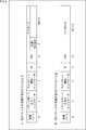
- FIG. 5 shows an example of the configuration of the header portion and the payload portion of the divided TLV packet.
- the 3-byte divided TLV packet header includes a synchronization byte, a transport error indicator, a TLV packet start indicator, and a PID.
- the synchronization byte is set to "0x47".
- the transport error indicator a flag indicating the presence / absence of a bit error in the divided TLV packet is specified.
- the TLV packet start indicator specifies a flag indicating whether or not the beginning of the TLV packet is included in the payload of the divided TLV packet. For example, in the divided TLV packet, when the TLV packet start indicator of the divided TLV packet header is "1", it indicates that the head of the TLV packet is included in the payload portion.
- the first TLV instruction is set in the first byte of the payload as shown in FIG. 5A.
- a value obtained by adding 1 to the value of the head TLV instruction indicates the number of bytes up to the start position of the head TLV packet in the payload of the divided TLV packet following the head TLV instruction.
- the TLV packet start indicator becomes "0"
- the head TLV instruction is not inserted as shown in FIG. 5B.
- the TLV packet start indicator of the divided TLV packet header becomes “1”
- the beginning of the TLV packet is included in the payload portion of the divided TLV packet, and the leading TLV instruction of 1 byte is inserted.
- the data stored there is 184 bytes (A in FIG. 5).
- the TLV packet start indicator of the divided TLV packet header is "0”
- the leading portion of the TLV packet is not included in the payload portion of the divided TLV packet, and the leading TLV instruction is not inserted, so that it is stored there.
- the data is 185 bytes (B in FIG. 5).
- $ PID is used to identify that the data in the payload is TLV data. Its value is defined as "0x002D”.
- synthesis is performed using a format using a multiplexed frame (TSMF header) as shown in FIG. 2 and a divided TLV packet shown in FIG.
- TSMF header a multiplexed frame
- FIG. 3 a TSMF header
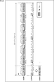
- a superframe is defined as a frame composed of a plurality of multiplex frames (TSMF).
- TSMF multiplex frames
- the transmission speed is 31.644 Mbps for 64QAM, 42.192 Mbps for 256QAM, and 64QAM and 256QAM are 3: 4 It becomes the relationship.
- the combining is performed in units of subframes, and the combining is performed in ascending order of carrier wave number (“after combining” in FIG. 6). However, only in the fourth subframe, synthesis is performed using only the 256 QAM carrier.
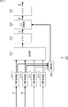
- FIG. 7 is a block diagram showing an example of the configuration of the demodulation IC 902 of the receiving device 20 having the current function.
- the demodulation IC 902 of the receiving apparatus 20 having the current function includes a control unit 910, TSMF processing units 911-1 to 911-4, a synthesis unit 912, a memory 913, a TLV conversion unit 914, and a memory 915.
- the control unit 910 controls the operation of each unit of the demodulation IC 902.
- the TSMF processing units 911-1 to 911-4 perform TSMF processing on the transmission stream from the internal demodulation unit or the external demodulation IC, and supply the target transmission stream to the combining unit 912. Further, the TSMF processing units 911-1 to 911-4 supply the header information of the TSMF header to the control unit 910.
- the combining unit 912 performs a combining process of combining the transmission streams from the TSMF processing units 911-1 to 911-4, and writes the resulting data into the memory 913.
- the TLV conversion unit 914 reads data from the memory 913, performs TLV conversion processing, and writes the resulting data to the memory 915.
- the data written in the memory 915 is read and output to a subsequent processing unit (for example, a system-on-chip).
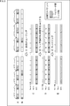
- FIG. 8 schematically illustrates the principle that jitter is included when processing a stream with the current function.
- AA in FIG. 8 represents a signal of a carrier wave of 64QAM, and this transmission stream is input to the TSMF processing section 911-1 (arrow A in FIG. 7).
- B in FIG. 8 represents a signal of a carrier wave of 64 QAM, and this transmission stream is input to the TSMF processing section 911-2 (arrow B in FIG. 7).
- These transmission streams include divided TLV packets.
- the transmission streams input to the TSMF processing section 911-1 and the TSMF processing section 911-2 are combined by the combining section 912 and written into the memory 913 (S1). Then, the data written in the memory 913 is read by the TLV converter 914. At this time, the data is read according to a predetermined clock, thereby realizing smoothing (S1).
- smoothing is a function of reading data written in a memory at a constant rate and continuously outputting the data.
- CC in FIG. 8 represents data (DATA) read from the memory 913, and (the data of) the divided TLV packet is input to the TLV converter 914 (arrow C in FIG. 7). Then, the VALID signal of the data (DATA) in the header portion of the divided TLV packet is set to the low level, and the header portion becomes invalid (S2).
- D in FIG. 8 represents data (DATA) output from the TLV conversion unit 914, and the divided TLV packet (data of the divided TLV packet in which the header part is invalid) is written to the memory 915 (FIG. 7 arrow D).
- E in FIG. 8 represents data (DATA) read from the memory 915 (arrow E in FIG. 7).
- ⁇ ⁇ ⁇ Jitter is caused by such random mixing of data having different numbers of bytes of 184 bytes and 185 bytes, but the current function cannot cope with such a case. Therefore, for the problem of jitter when 184 bytes and 185 bytes of data are mixed as payload data to be written to the memory, what kind of configuration can be used to perform smoothing with the minimum amount of memory Is required.
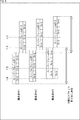
- the propagation delay time difference between the carrier waves is large, it becomes difficult to search for the head position of the superframe intended at the time of transmission in the processing on the receiving side. Therefore, for example, in the transmodulation operation specification (JLabs @ SPEC-034) formulated by the Japan Cable Laboratory, the phase difference range of the superframe at the time of reception is determined, and this range is defined in the transmission section up to the reception device 20.
- the propagation delay difference is absorbed or controlled so as to be satisfied.
- the arrival time difference needs to be less than 1/2 of one superframe. Since the first frame of the superframe must be included in the section less than 1/2, for example, in the above-mentioned operation specification (JLabs @ SPEC-034), as shown in FIG.
- the phase difference range is less than 1/6 less the superframe.
- each of the carriers # 1 to # 3 passes through a different transmission path, for example, the delay between the carriers may be large, and each of the carriers # 1 to # 3 has a half superframe or more. If it is shifted, the head of the frame cannot be detected and cannot be combined. Therefore, for example, as specified in the above-mentioned operation specification (JLabs @ SPEC-034), it is necessary for the receiving side to cope with up to 1/6 superframe delay.
- each carrier may be delayed and each carrier needs to be synchronized, and the receiving side must support a predetermined delay (for example, the receiving side must support up to 1/6 superframe delay depending on the operation specifications).
- a predetermined delay for example, the receiving side must support up to 1/6 superframe delay depending on the operation specifications.
- a new function to which the present technology is applied makes it possible to reduce jitter when processing a stream corresponding to a plurality of carriers. Also, with the new function to which the present technology is applied, when each carrier is delayed, the receiving side can cope with a predetermined delay (for example, corresponding to a delay required on the receiving side according to operation specifications).
- a predetermined delay for example, corresponding to a delay required on the receiving side according to operation specifications.
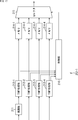
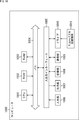
- FIG. 10 is a block diagram illustrating an example of a configuration of the receiving device 20 having a new function.
- the receiving device 20 having the new function includes tuners 201-1 to 201-4, demodulation ICs 202-1 to 202-4, and a system-on-chip 203.
- the tuner 201-1 receives the broadcast signal transmitted from the transmitting apparatus 10, performs necessary processing, and supplies the resulting received signal (carrier # 1 signal) to the demodulation IC 202-1.
- the tuners 201-2 to 201-4 perform necessary processing on the broadcast signal in the same manner as the tuner 201-1, and convert the resulting reception signals (carrier signals # 2 to # 4) into demodulation ICs 202-201. 2 to 202-4.
- the demodulation IC 202-2 performs demodulation processing (for example, demodulation such as 64QAM or 256QAM) on the received signal (carrier # 2 signal) supplied from the tuner 201-2, and converts the resulting transmission stream into demodulation IC 202 Supply -1.
- demodulation processing for example, demodulation such as 64QAM or 256QAM
- the demodulation IC 202-3 and the demodulation IC 202-4 perform demodulation processing on the received signal (signals of the carrier waves # 3 and # 4), and transmit the resulting transmission stream to the demodulation IC 202-202.
- Supply 1 demodulation processing
- the demodulation IC 202-1 includes a control unit 210, a demodulation unit 211, TSMF processing units 212-1 to 212-4, TLV conversion units 213-1 to 213-4, memories 214-1 to 214-4, and a selector 215. Is done.
- the demodulation IC 202-1 receives the received signal from the tuner 201-1 and the transmission streams from the demodulation ICs 202-2 to 202-4.
- the control unit 210 controls the operation of each unit of the demodulation IC 202-1.
- the control unit 210 includes a processor such as a microcontroller.
- the demodulation unit 211 performs demodulation processing (eg, demodulation such as 64QAM or 256QAM) on the signal received from the tuner 201-1 (signal of the carrier wave # 1), and converts the resulting transmission stream into a TSMF processing unit 212- Supply 1
- demodulation processing eg, demodulation such as 64QAM or 256QAM
- TSMF processing section 212-1 performs TSMF processing on TSMF packets with respect to the transmission stream supplied from demodulation section 211.
- a TSMF packet (TSMF header thereof) is detected from a transmission stream extracted from a received signal (signal of carrier # 1), or header information (extended information) of the TSMF header is extracted. Processing and the like are performed.
- the TSMF processing unit 212-1 supplies the header information (extended information) of the extracted TSMF header to the control unit 210. Further, the TSMF processing unit 212-1 supplies the transmission stream supplied from the demodulation unit 211 to the TLV conversion unit 213-1.
- the TSMF processing units 212-2 to 212-4 perform TSMF processing on transmission streams from the external demodulation ICs 202-2 to 202-4, respectively, and perform header information (extension) of the TSMF header. ) Is supplied to the control unit 210. Further, the TSMF processing units 212-2 to 212-4 supply the transmission streams from the external demodulation ICs 202-2 to 202-4 to the TLV conversion units 213-2 to 213-4, respectively.
- the TLV conversion unit 213-1 writes the data of (the payload part of) the divided TLV packet included in the transmission stream supplied from the TSMF processing unit 212-1 to the memory 214-1. Further, the TLV converter 213-1 supplies information indicating the amount of data written to the memory 214-1 to the controller 210.
- the TLV converters 213-2 to 213-4 store the data of the (payload portion of) the divided TLV packets from the TSMF processing units 212-2 to 212-4 in the memory 214-2. To 214-4. Further, the TLV converters 213-2 to 213-4 supply the information indicating the amounts of data written to the memories 214-2 to 214-4 to the controller 210, respectively.
- the memories 214-1 to 214-4 are buffer memories each having a predetermined capacity (for example, a semiconductor storage device such as a random access memory (RAM)).
- a predetermined capacity for example, a semiconductor storage device such as a random access memory (RAM)
- the control unit 210 is supplied with header information (extended information) of the TSMF header from the TSMF processing units 212-1 to 212-4 and information indicating the write data amount from the TLV conversion units 213-1 to 213-4. You.
- the control unit 210 calculates the total data amount written in the predetermined frame section and the time of the predetermined frame section based on the write data amount and the header information (extended information), and performs smoothing based on the calculation result. A corresponding data reading clock is generated.
- the control unit 210 reads the data written in the memories 214-1 to 214-4 in a predetermined order by controlling the selector 215 based on the generated clock.
- control unit 210 determines the timing to start reading data written in the memories 214-1 to 214-4.
- the control unit 210 controls (starts) the data reading start based on the determined reading start timing.
- the data (combined data) read from the memories 214-1 to 214-4 is continuously output at a constant rate and output to the system-on-chip 203 as an output stream.
- the system-on-chip 203 performs predetermined processing such as decoding on an output stream input from the (selector 215 of) the demodulation IC 202-1, and outputs the resulting video data (or image data) to a subsequent display. (Not shown), and outputs the audio data to a subsequent audio output device (not shown).
- the display is, for example, a display device (display device) such as a liquid crystal display (LCD: Liquid Crystal Display) or an organic EL display (OLED: Organic Light Emitting Diode).
- display device such as a liquid crystal display (LCD: Liquid Crystal Display) or an organic EL display (OLED: Organic Light Emitting Diode).
- LCD Liquid Crystal Display
- OLED Organic Light Emitting Diode
- the display displays a video (or image) corresponding to the video data (or image data) input from the system-on-chip 203.
- the audio output device is, for example, a speaker.
- the sound output device outputs a sound (sound) according to the sound data processed by the system-on-chip 203.
- the receiving device 20 having the new function is configured as described above.
- the new functions mainly include a header removal / smoothing function for solving the above-mentioned jitter problem and a delay handling function for solving the above-mentioned delay handling problem. Therefore, the details of the header removal / smoothing function and the delay handling function will be described below in order.
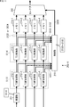
- FIG. 11 shows the operation of each unit in the demodulation IC 202-1 corresponding to the header removal / smoothing function and the signal flow.
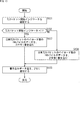
- FIGS. 12 to 14 are flowcharts illustrating the flow of processing corresponding to the header removal / smoothing function.
- the notation “S1XX” corresponds to each step S1XX in FIGS. 12 to 14, and in the description of FIGS. 12 to 14, the operation and signal of each unit shown in FIG. Will be referred to as appropriate.
- FIG. 11 it is assumed that four waves of carrier waves # 1 to # 4 are received by the receiving device 20.
- step S111 the demodulation unit 211 performs a demodulation process on the received signal (the signal of the first carrier # 1) input thereto.
- the transmission stream obtained as a result of this demodulation processing is supplied to the TSMF processing unit 212-1. Further, the TSMF processing units 212-2 to 212-4 are supplied with transmission streams from the external demodulation ICs 202-2 to 202-4, respectively. These transmission streams are extracted from the second to fourth carrier waves # 2 to # 4.
- TSMF processing by the TSMF processing units 212-1 to 212-4 (S113) and TLV conversion processing by the TLV conversion units 213-1 to 213-4 (S114) are sequentially performed.
- N 1 is set as an initial value of the TSMF processing unit 212-N and the TLV conversion unit 213-N (S112), and the value of N is maintained until N> 4 (“YES” of S116).
- the TSMF processing section 212-1 performs TSMF processing (S113), and supplies a transmission stream including a TSMF packet identified by, for example, identification information (stream_id, original_network_id) to the TLV conversion section 213-1.
- S113 TSMF processing
- the header information extended information
- the TLV conversion unit 213-1 performs a TLV conversion process for converting the divided TLV packet into a TLV packet (S114).
- FIG. 13 is a flowchart illustrating details of the TLV conversion process corresponding to step S114 in FIG.
- step S131 the TLV converter 213-1 checks the TLV packet start indicator included in the divided TLV packet header added to the divided TLV packet.
- step S132 the TLV converter 213-1 determines whether the TLV packet start indicator is "1" based on the result of checking the header.
- step S132 If it is determined in step S132 that “1” is designated as the TLV packet start indicator, the process proceeds to step S133.
- step S133 the TLV converter 213-1 writes the 184-byte data of the payload portion of the divided TLV packet into the memory 214-1.
- the TLV packet start indicator stored in the 3-byte divided TLV packet header is “1”
- a 1-byte head TLV instruction is inserted into the payload section, and a 3-byte header section is added. Since a 1-byte head TLV indication area is secured, the data of the payload portion in the divided TLV packet of 188 bytes is the remaining 184 bytes (A in FIG. 5).
- step S132 determines whether “0” is specified as the TLV packet start indicator. If it is determined in step S132 that “0” is specified as the TLV packet start indicator, the process proceeds to step S134.
- step S134 the TLV converter 213-1 writes the 185-byte data of the payload of the divided TLV packet into the memory 214-1.
- the leading TLV instruction is not inserted into the payload part, and one other than the three-byte header part is added. Since it is not necessary to secure an area for indicating the leading TLV of the byte, in the divided TLV packet of 188 bytes, the data of the payload portion is the remaining 185 bytes (B in FIG. 5).
- step S133 or S134 When 184 bytes or 185 bytes of data are written to the memory 214-1 in the process of step S133 or S134, the process proceeds to step S135.
- step S135 the TLV converter 213-1 notifies the controller 210 of the amount of data (for example, the number of bytes) written in the memory 214-1.
- step S135 ends, the process returns to step S114 in FIG. 12, and the subsequent processes are repeated.
- the TLV conversion processing (S114) is performed, and the divided TLV packets are stored in the memories 214-2 to 214-4.
- the 184-byte or 185-byte data of the payload section is written (S133 or S134 in FIG. 13).
- the amounts of data to be written to the memories 214-2 to 214-4 are notified to the controller 210 (S135).
- step S117 it is determined whether to end the processing.
- step S117 If it is determined in step S117 that the process is not to be ended, the process returns to step S111, and the above-described process is repeated.
- step S117 the carrier wave corresponding process in FIG. 12 is ended.
- the TSMF processing (S113) by the TSMF processing units 212-1 to 212-4 is sequentially performed for each carrier, and further, the TLV conversion units 213-1 to 213 are further performed.
- the TLV conversion process (S114) according to ⁇ 4 is sequentially performed for each carrier, the TSMF process (S113) and the TLV conversion process (S114) are actually performed for each carrier as shown in FIG. Executed in parallel.
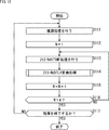
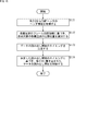
- step S151 the control unit 210 acquires the header information (extended information) of the TSMF header notified from the TSMF processing units 212-1 to 212-4.
- step S152 the control unit 210 acquires the write data amount notified from the TLV conversion units 213-1 to 213-4.
- step S153 the control unit 210 determines, based on the notified write data amount (eg, the number of bytes), the total data amount (eg, the total number of bytes) written to the memories 214-1 to 214-4 in one superframe section. ) Is calculated.
- the notified write data amount eg, the number of bytes
- the total data amount eg, the total number of bytes
- step S154 the control unit 210 calculates the time of one superframe section based on the notified header information (extended information) of the TSMF header.
- the time of one superframe section can be calculated by using the frame position information (frame_position) included in the extended information of the header information.
- step S155 the control unit 210 generates a clock for reading data corresponding to smoothing based on the calculated total amount of data written in one superframe section and the time of one superframe section.
- a constant rate for example, bit rate
- a clock corresponding to a rate (unit: Mbps) is generated.
- a technique relating to smoothing for example, a technique disclosed in Japanese Patent Application Laid-Open No. 2012-205266 is known, and here, a similar technique can be used.
- step S156 the control section 210 reads the data written in the memories 214-1 to 214-4 by controlling the selector 215 based on the generated data reading clock.
- control unit 210 can determine the reading order of the memories 214-1 to 214-4 as follows, for example.
- the control unit 210 can determine the reading order of the memories 214-1 to 214-4 in which the data obtained from the signals of the respective carrier waves (carrier waves # 1 to # 4) are written based on the arrangement order of the slots. .
- information such as header information (extended information) of the TSMF header may be used.
- step S157 it is determined whether to end the processing.
- step S157 If it is determined in step S157 that the process is not to be ended, the process returns to step S151, and the above-described process is repeated. If it is determined in step S157 that the process is to be terminated, the data read clock control process of FIG. 14 is terminated.
- the header information (extended information) of the TSMF header from the TSMF processing units 212-1 to 212-4 and the TLV conversion are performed by the carrier wave corresponding processing (FIGS. 12 and 13) executed in parallel. Since the write data amount is sequentially notified from the units 213-1 to 213-4 (S151 and S152 in FIG. 11), the control unit 210 performs smoothing based on the header information (extended information) and the write data amount. Is generated (S153 to S155 in FIG. 11) and the data reading is controlled (S156 in FIG. 11), thereby realizing smoothing.
- the above-mentioned problem of jitter can be solved by the header removal / smoothing function as a new function.
- the header removal / smoothing function when writing the data of the divided TLV packet to each of the memories 214-1 to 214-4, the divided TLV packet header is removed, and the data of the payload portion is written (
- smoothing is performed based on the amount of data to be written (the processing shown in FIG. 14). For example, when data is written to the memories 214-1 to 214-4, even when data having different numbers of bytes of 184 bytes and 185 bytes are randomly mixed, more complete smoothing can be performed.
- jitter can be reduced (reduced) when data having different numbers of bytes are mixed at random in writing data, so that the above-mentioned problem of jitter can be solved (the minimum amount of jitter).
- a configuration in which smoothing is performed by a memory can be provided). Further, comparing the configuration of the demodulation IC 202-1 (FIG. 10) of the receiving device 20 having the new function with the configuration of the demodulating IC 902 (FIG. 7) of the receiving device 20 having the current function, In FIG. 7), it is necessary to perform the smoothing twice. However, in the demodulation IC 202-1 (FIG. 10) of the new function, only one smoothing is required, so that it is possible to reduce, for example, memories and circuits.
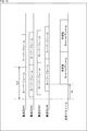
- FIG. 15 shows an example of setting data read start timing by the delay handling function.
- each carrier wave # 1 to # 4 is received by the receiving device 20.
- the transmission streams corresponding to the signals of the carrier waves # 1 to # 4 are input to the TSMF processing units 212-1 to 212-4, respectively.
- each carrier wave is delayed.
- the delay amount (delay time) of the carrier # 2, the carrier # 3, and the carrier # 4 with respect to the carrier # 1 is less than 1/2 superframe section (a time corresponding to the length of one superframe). Less than 1/2).
- the memories 214-1 to 214-4 each have a capacity corresponding to the data of the 3/2 superframe section (1 superframe section + 1/2 superframe section).
- TSMF processing is performed by the TSMF processing units 212-1 to 212-4
- TLV conversion processing is performed by the TLV conversion units 213-1 to 213-4.
- the data obtained from the signals of the four carrier waves # 1 to # 4 are sequentially written in each of the signals # 1 to # 4.
- the control unit 210 performs control on each carrier to be combined according to the frame position information (frame_position). Identify the start position. In the example of FIG. 15, among the carrier waves # 1 to # 4, the head position of the carrier wave # 1 (reference carrier wave) is identified.
- the control unit 210 calculates a read start time Ts as a timing to start reading data written in the memories 214-1 to 214-4.
- the read start time Ts based on the top of the reference carrier wave # 1 (the most advanced carrier wave # 1) among the four carrier waves # 1 to # 4 is equal to the length of one superframe.
- the time Tsf corresponding to this, the relationship as shown in the following equation (1) is satisfied.
- the read start time Ts is, for example, as shown in FIG. 15, when the carrier wave # 1 that is the most delayed among the four carrier waves # 1 to # 4 is referenced to the head of the carrier wave # 1 that is the most advanced.
- the timing should be later in time than the beginning of 4.
- control unit 210 controls the selector 215 so that reading of the data written in the memories 214-1 to 214-4 is started at the timing of the reading start time Ts.
- the reading start time Ts is longer than the leading time of the carrier wave # 4, which is the most delayed. If later, it is possible to absorb the delay of each carrier of carrier # 2, carrier # 3, and carrier # 4 with respect to carrier # 1.
- step S171 the control unit 210 acquires header information (extended information) of the TSMF header notified from the TSMF processing units 212-1 to 212-4.
- step S172 the control unit 210 identifies the start position of each carrier to be combined based on the frame position information (frame_position) included in the notified header information (extended information).
- frame_position the frame position information included in the notified header information (extended information).
- step S173 the control unit 210 determines the timing to start reading data written in the memories 214-1 to 214-4.
- the read start time Ts that satisfies the relationship of the above equation (1) is determined as the time from the head position of the identified carrier wave # 1 to the start of the read.
- step S174 the control unit 210 starts reading data written in the memories 214-1 to 214-4 at the read start time Ts based on the determined read start timing. Control.
- the delay handling function as a new function can solve the above-described delay handling problem.
- memories 214-1 to 214-4 are provided for each of a plurality of carriers (for example, carriers # 1 to # 4), and the timing of the read start time Ts that satisfies the relationship of the above equation (1) is provided. Then, since the reading of the data written in the memories 214-1 to 214-4 is started to absorb the delay of each carrier, the receiving side can cope with a predetermined delay (for example, depending on the operation specification, (Corresponding to the delay required on the receiving side) (each carrier having a delay can be synchronized).
- a predetermined delay for example, depending on the operation specification, (Corresponding to the delay required on the receiving side) (each carrier having a delay can be synchronized).
- the demodulation IC 202-1 (FIG. 10) of the receiving apparatus 20 having the new function can cope with a predetermined delay on the receiving side by the configuration shown in FIG. Since a circuit is not required, the number of circuits can be reduced.
- FIG. 17 is a block diagram showing another example of the configuration of the demodulation IC corresponding to the delay handling function.
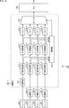
- the demodulation IC 202-1 includes a demodulation unit 211, TSMF processing units 212-1 to 212-4, memories 214-1 to 214-4, and a selector 215. That is, the demodulation IC 202-1 in FIG. 17 is different from the demodulation IC 202-1 in FIG. 10 in that the TLV converters 213-1 to 213-4 are omitted.
- TSMF processing section 212-1 performs TSMF processing on the transmission stream from demodulation section 211, and writes the resulting data to memory 214-1.
- the TSMF processing units 212-2 to 212-4 perform TSMF processing on transmission streams from the external demodulation ICs 202-2 to 202-4, respectively, and convert the resulting data into Writing to the memories 214-2 to 214-4, respectively.
- the control unit 210 is notified of the header information (extended information) of the TSMF header from the TSMF processing units 212-1 to 212-4.
- the control unit 210 determines, based on the header information (extended information) of the notified TSMF header, the timing of starting to read the data written in each of the memories 214-1 to 214-4 by using the relationship of the above equation (1).
- the read start time Ts that satisfies is calculated.
- control unit 210 controls the selector 215 so that reading of the data written in the memories 214-1 to 214-4 is started at the timing of the reading start time Ts.
- the TLV converters 213-1 to 213-4 are omitted, but the TLV packet as a fixed-length packet is used instead of the TLV packet as a variable-length packet.
- the data can be directly written to the memories 214-1 to 214-4 without passing through the TLV converters 213-1 to 213-4. In such a case, the delay handling function is applied.
- the demodulation IC 202-1 on the receiving side processes (combines) a fixed-length packet such as a TS packet, only the delay-compatible function among the new functions described above is applied. can do.
- the receiving device 20 (FIG. 1) is described as being configured as a fixed receiver such as a television receiver or a set-top box (STB). , A game machine, a personal computer, a network storage, and the like. Further, the receiving device 20 is not limited to a fixed receiver. For example, a mobile receiver such as a smartphone, a mobile phone, or a tablet computer, a vehicle-mounted device such as a vehicle-mounted television, or a head-mounted display (HMD: Head) An electronic device such as a wearable computer such as a mounted display may be included.
- a mobile receiver such as a smartphone, a mobile phone, or a tablet computer
- a vehicle-mounted device such as a vehicle-mounted television
- HMD head-mounted display
- An electronic device such as a wearable computer such as a mounted display may be included.
- the demodulation IC 202-1 (demodulation device) included in the reception device 20 may be regarded as a reception device or a demodulation device to which the present technology is applied.
- the number of the plurality of carrier waves is 2 to 4, but the number of the carrier waves may be any number as long as it is 2 or more (for example, it may be 5 or more).
- tuners 201-1 to 201-N and demodulation ICs 202-1 to 202-N are provided according to the number of N carrier waves (N is an integer of 2 or more).
- N is an integer of 2 or more.
- the demodulation IC 202-1 one demodulation unit 211, N TSMF processing units 212-1 to 212-N, N TLV conversion units 213-1 to 213-N, N memories 214-1 to 214-N are provided, respectively.
- the tuner 201, the demodulation IC 202, the TSMF processing unit 212, the TLV conversion unit 213, and the memory 214 are not limited to the same number as the number of carriers, but may be provided with a number larger than the number of carriers.
- the receiving device 20 (FIG. 1) having a communication function is configured such that various servers are connected to a communication line such as the Internet.
- Various data such as contents and applications may be received by accessing various servers and performing bidirectional communication via a communication line such as the Internet.
- FIG. 18 is a diagram illustrating a configuration example of hardware of a computer that executes the series of processes described above by a program.
- a CPU Central Processing Unit
- ROM Read Only Memory
- RAM Random Access Memory
- An input / output interface 1005 is further connected to the bus 1004.
- An input unit 1006, an output unit 1007, a recording unit 1008, a communication unit 1009, and a drive 1010 are connected to the input / output interface 1005.
- the input unit 1006 includes a keyboard, a mouse, a microphone, and the like.
- the output unit 1007 includes a display, a speaker, and the like.
- the recording unit 1008 includes a hard disk, a nonvolatile memory, and the like.
- the communication unit 1009 includes a network interface and the like.
- the drive 1010 drives a removable recording medium 1011 such as a magnetic disk, an optical disk, a magneto-optical disk, or a semiconductor memory.
- the CPU 1001 loads the program recorded in the ROM 1002 or the recording unit 1008 into the RAM 1003 via the input / output interface 1005 and the bus 1004, and executes the program. A series of processing is performed.
- the program executed by the computer 1000 can be provided by being recorded on a removable recording medium 1011 as a package medium or the like, for example.
- the program can be provided via a wired or wireless transmission medium such as a local area network, the Internet, or digital satellite broadcasting.
- the program can be installed in the recording unit 1008 via the input / output interface 1005 by attaching the removable recording medium 1011 to the drive 1010. Further, the program can be received by the communication unit 1009 via a wired or wireless transmission medium and installed in the recording unit 1008. In addition, the program can be installed in the ROM 1002 or the recording unit 1008 in advance.
- the processing performed by the computer according to the program does not necessarily have to be performed in chronological order according to the order described in the flowchart. That is, the processing performed by the computer according to the program includes processing executed in parallel or individually (for example, parallel processing or processing by an object). Further, the program may be processed by one computer (processor) or may be processed in a distributed manner by a plurality of computers.
- the present technology can have the following configurations.
- the transmission stream transmitted for each of the plurality of carrier waves includes a divided variable-length packet obtained by dividing a variable-length packet, the data of the payload portion among the header portion and the payload portion constituting the divided variable-length packet is transmitted.
- a control unit that controls a clock for reading the data written in the memory based on an amount of data written in a predetermined frame section and a time of the predetermined frame section when sequentially writing the data in the memory; Receiver.
- a plurality of conversion units provided according to the number of the carrier waves, A plurality of memories provided corresponding to the plurality of conversion units, The receiving device according to (1), wherein each of the conversion units removes the header from the input variable fragment length packet and writes the data of the payload into the corresponding memory.
- the control unit includes: Based on the write data amount notified from each of the conversion units, calculate the total data amount written to the plurality of memories in the section of the predetermined frame, Based on the header information of the multiplex frame header included in the predetermined frame, calculate the time of the section of the predetermined frame, The receiving device according to (2), wherein the clock for reading the data written in each of the plurality of memories is controlled based on a result of the calculation.
- the clock is a clock corresponding to a constant rate obtained from the relationship between the total amount of data written in the section of the predetermined frame and the time of the section of the predetermined frame.
- the receiving device controls an order in which the data is read from a plurality of memories based on an arrangement order of slots allocated in a predetermined unit for each carrier.
- the control unit when a delay occurs in the carrier, a read start time Ts with reference to the head of a reference carrier of the plurality of carriers, Ts, the time according to the length of the predetermined frame
- Tsf when Tsf is set, control is performed so that reading of the data written in each of the plurality of memories is started at a timing of the read start time Ts (where Ts ⁇ 1/2 ⁇ Tsf).
- the delay is a delay of less than 1/2 of a time corresponding to the length of the predetermined frame, between each of the plurality of carriers,
- the read start time Ts is a timing that is later in time than the head of the latest carrier when the carrier that is the most advanced among the plurality of carriers is used as a reference carrier.
- Receiving device (8) The receiving device according to (6) or (7), wherein the control unit identifies heads of the plurality of carrier waves based on frame position information of the carrier wave included in header information of the multiplexed frame header. (9) The receiving device according to any one of (1) to (8), wherein the predetermined frame includes a frame configured by a plurality of multiplexed frames.
- Each of the conversion units writes to the corresponding memory in a case where the payload of the divided variable length packet includes the head of the variable length packet and in a case where the head of the variable length packet is not included.
- the receiving device is When the transmission stream transmitted for each of the plurality of carrier waves includes a divided variable-length packet obtained by dividing a variable-length packet, the data of the payload portion of the header portion and the payload portion constituting the divided variable-length packet is transmitted.
- a receiving method for controlling a clock for reading out the data written in the memory based on an amount of data written in a section of a predetermined frame and a time of the section of the predetermined frame when sequentially writing the data in the memory.
- Transmission system ⁇ 10 ⁇ transmission device, ⁇ 20 ⁇ reception device, ⁇ 30 ⁇ CATV transmission line, ⁇ 201, 201-1 to 201-4 ⁇ tuner, ⁇ 202, 202-1 to 202-4 ⁇ demodulation IC, ⁇ 203 ⁇ system on chip (SoC), ⁇ 210 ⁇ control Unit, ⁇ 211 ⁇ demodulation unit, ⁇ 212, 212-1 to 212-4 ⁇ TSMF processing unit, ⁇ 213, 213-1 to 213-4 ⁇ TLV conversion unit, ⁇ 214, 214-1 to 214-4 ⁇ memory, ⁇ 215 ⁇ selector, ⁇ 1000 ⁇ computer, ⁇ 1001 ⁇ CPU
Landscapes
- Engineering & Computer Science (AREA)
- Signal Processing (AREA)
- Computer Networks & Wireless Communication (AREA)
- Computer Hardware Design (AREA)
- Time-Division Multiplex Systems (AREA)
- Two-Way Televisions, Distribution Of Moving Picture Or The Like (AREA)
- Synchronisation In Digital Transmission Systems (AREA)
Abstract
Description
2.変形例
3.コンピュータの構成
図1は、本技術を適用した伝送システムの一実施の形態の構成を示す図である。なお、システムとは、複数の装置が論理的に集合したものをいう。
図2は、多重フレームの構成の例を示す図である。
図3は、多重フレームヘッダ(TSMFヘッダ)のシンタックスの概要を示す図である。
図4は、TLVパケットと分割TLVパケットの構成の例を示す図である。
ここで、本技術を適用した新機能との比較のために、図7乃至図9を参照して、現状の機能を有する受信装置20(の復調IC902)の構成と動作を説明する。
ここで、図8は、現状の機能でストリームを処理する際にジッタが含まれる原理を模式的に示している。
また、複数搬送波伝送方式では、搬送波の順序(carrier_sequence)と、フレーム位置情報(frame_position)により、多重フレーム(TSMF)の配置順を指定するため、送信側の処理と受信側の処理において搬送波間のフレームの位相がそろっていることが前提とされる。そのため、伝送において搬送波ごとに伝送遅延時間が異なる場合には、受信側の処理で搬送波間の位相をそろえる必要がある。
図10は、新機能を有する受信装置20の構成の例を示すブロック図である。
まず、図11乃至図14を参照しながら、新機能のうち、ヘッダ除去・スムージング機能の例について説明する。
図12のフローチャートを参照して、復調IC202-1における復調部211、TSMF処理部212-1乃至212-4、及びTLV変換部213-1乃至213-4により実行される搬送波対応処理の流れを説明する。
次に、図14のフローチャートを参照して、復調IC202-1の制御部210により実行される、データ読み出しクロック制御処理の流れを説明する。なお、このデータ読み出しクロック制御処理は、上述した搬送波対応処理(図12,図13)と並列に実行される。
次に、図15乃至図17を参照しながら、新機能のうち、遅延対応機能の例について説明する。
次に、図16のフローチャートを参照して、復調IC202-1の制御部210により実行される、データ読み出し開始タイミング制御処理の流れを説明する。なお、このデータ読み出し開始タイミング制御処理は、上述した搬送波対応処理(図12,図13)及びデータ読み出しクロック制御処理(図14)と並列に実行することができる。
図17は、遅延対応機能に対応した復調ICの他の構成の例を示すブロック図である。
また、上述した説明では、受信装置20(図1)は、テレビ受像機やセットトップボックス(STB)などの固定受信機として構成されるとして説明したが、固定受信機には、例えば、録画機、ゲーム機、パーソナルコンピュータ、ネットワークストレージなどを含めるようにしてもよい。さらに、受信装置20としては、固定受信機に限らず、例えば、スマートフォンや携帯電話機、タブレット型コンピュータ等のモバイル受信機、車載テレビ等の車両に搭載される車載機器、ヘッドマウントディスプレイ(HMD:Head Mounted Display)等のウェアラブルコンピュータなどの電子機器を含めるようにしてもよい。
また、伝送システム1(図1)においては、図示していないが、インターネット等の通信回線に対し、各種のサーバが接続されるようにして、通信機能を有する受信装置20(図1)が、インターネット等の通信回線を介して、各種のサーバにアクセスして双方向の通信を行うことで、コンテンツやアプリケーション等の各種のデータを受信できるようにしてもよい。
なお、本明細書において記述されている用語は、一例であって、他の用語が用いられるのを意図的に排除するものではない。例えば、上述した説明において、フレームは、例えば、パケットなどの他の用語で置き換えられる場合がある。
複数の搬送波ごとに伝送される伝送ストリームとして、可変長パケットを分割した分割可変長パケットが含まれる場合に、前記分割可変長パケットを構成するヘッダ部とペイロード部のうち、前記ペイロード部のデータを順次メモリに書き込むに際して、所定のフレームの区間に書き込まれたデータ量及び前記所定のフレームの区間の時間に基づいて、前記メモリに書き込まれた前記データを読み出すためのクロックを制御する制御部を備える
受信装置。
(2)
前記搬送波の数に応じて複数設けられる変換部と、
複数の前記変換部に対応して複数設けられる前記メモリと
をさらに備え、
前記変換部のそれぞれは、入力される前記分割可変長パケットから前記ヘッダ部を除去して前記ペイロード部のデータを、対応する前記メモリに書き込む
前記(1)に記載の受信装置。
(3)
前記制御部は、
前記変換部のそれぞれから通知される書き込みデータ量に基づいて、前記所定のフレームの区間に複数の前記メモリに書き込まれた全データ量を計算し、
前記所定のフレームに含まれる多重フレームヘッダのヘッダ情報に基づいて、前記所定のフレームの区間の時間を計算し、
それらの計算の結果に基づいて、複数の前記メモリにそれぞれ書き込まれた前記データを読み出すための前記クロックを制御する
前記(2)に記載の受信装置。
(4)
前記クロックは、前記所定のフレームの区間に書き込まれた全データ量と、前記所定のフレームの区間の時間との関係から得られる一定のレートに対応したクロックである
前記(1)乃至(3)のいずれかに記載の受信装置。
(5)
前記制御部は、前記搬送波ごとに所定の単位で割り当てられるスロットの配列順に基づいて、複数の前記メモリから前記データを読み出す順番を制御する
前記(3)又は(4)に記載の受信装置。
(6)
前記制御部は、前記搬送波に遅延が生じている場合に、複数の前記搬送波のうち基準の搬送波の先頭を基準とした読み出し開始時間をTsとし、前記所定のフレームの長さに応じた時間をTsfとしたとき、前記読み出し開始時間Ts(ただし、Ts < 1/2 × Tsf)のタイミングで、複数の前記メモリにそれぞれ書き込まれた前記データの読み出しを開始するように制御する
前記(3)に記載の受信装置。
(7)
前記遅延は、複数の前記搬送波のそれぞれの間で、前記所定のフレームの長さに応じた時間の1/2未満の遅延であり、
前記読み出し開始時間Tsは、複数の前記搬送波のうち最も進んでいる搬送波を基準の搬送波としたときに、最も遅れている搬送波の先頭よりも時間的に後のタイミングとなる
前記(6)に記載の受信装置。
(8)
前記制御部は、前記多重フレームヘッダのヘッダ情報に含まれる前記搬送波のフレーム位置情報に基づいて、複数の前記搬送波の先頭を識別する
前記(6)又は(7)に記載の受信装置。
(9)
前記所定のフレームは、複数の多重フレームで構成されるフレームを含む
前記(1)乃至(8)のいずれかに記載の受信装置。
(10)
前記変換部のそれぞれは、前記分割可変長パケットの前記ペイロード部に、前記可変長パケットの先頭が含まれる場合と、前記可変長パケットの先頭が含まれない場合とで、対応する前記メモリに書き込む前記ペイロード部のデータ量が異なる
前記(2)又は(3)に記載の受信装置。
(11)
復調装置として構成される
前記(1)乃至(10)のいずれかに記載の受信装置。
(12)
受信装置が、
複数の搬送波ごとに伝送される伝送ストリームとして、可変長パケットを分割した分割可変長パケットが含まれる場合に、前記分割可変長パケットを構成するヘッダ部とペイロード部のうち、前記ペイロード部のデータを順次メモリに書き込むに際して、所定のフレームの区間に書き込まれたデータ量及び前記所定のフレームの区間の時間に基づいて、前記メモリに書き込まれた前記データを読み出すためのクロックを制御する
受信方法。
Claims (12)
- 複数の搬送波ごとに伝送される伝送ストリームとして、可変長パケットを分割した分割可変長パケットが含まれる場合に、前記分割可変長パケットを構成するヘッダ部とペイロード部のうち、前記ペイロード部のデータを順次メモリに書き込むに際して、所定のフレームの区間に書き込まれたデータ量及び前記所定のフレームの区間の時間に基づいて、前記メモリに書き込まれた前記データを読み出すためのクロックを制御する制御部を備える
受信装置。 - 前記搬送波の数に応じて複数設けられる変換部と、
複数の前記変換部に対応して複数設けられる前記メモリと
をさらに備え、
前記変換部のそれぞれは、入力される前記分割可変長パケットから前記ヘッダ部を除去して前記ペイロード部のデータを、対応する前記メモリに書き込む
請求項1に記載の受信装置。 - 前記制御部は、
前記変換部のそれぞれから通知される書き込みデータ量に基づいて、前記所定のフレームの区間に複数の前記メモリに書き込まれた全データ量を計算し、
前記所定のフレームに含まれる多重フレームヘッダのヘッダ情報に基づいて、前記所定のフレームの区間の時間を計算し、
それらの計算の結果に基づいて、複数の前記メモリにそれぞれ書き込まれた前記データを読み出すための前記クロックを制御する
請求項2に記載の受信装置。 - 前記クロックは、前記所定のフレームの区間に書き込まれた全データ量と、前記所定のフレームの区間の時間との関係から得られる一定のレートに対応したクロックである
請求項3に記載の受信装置。 - 前記制御部は、前記搬送波ごとに所定の単位で割り当てられるスロットの配列順に基づいて、複数の前記メモリから前記データを読み出す順番を制御する
請求項3に記載の受信装置。 - 前記制御部は、前記搬送波に遅延が生じている場合に、複数の前記搬送波のうち基準の搬送波の先頭を基準とした読み出し開始時間をTsとし、前記所定のフレームの長さに応じた時間をTsfとしたとき、前記読み出し開始時間Ts(ただし、Ts < 1/2 × Tsf)のタイミングで、複数の前記メモリにそれぞれ書き込まれた前記データの読み出しを開始するように制御する
請求項3に記載の受信装置。 - 前記遅延は、複数の前記搬送波のそれぞれの間で、前記所定のフレームの長さに応じた時間の1/2未満の遅延であり、
前記読み出し開始時間Tsは、複数の前記搬送波のうち最も進んでいる搬送波を基準の搬送波としたときに、最も遅れている搬送波の先頭よりも時間的に後のタイミングとなる
請求項6に記載の受信装置。 - 前記制御部は、前記多重フレームヘッダのヘッダ情報に含まれる前記搬送波のフレーム位置情報に基づいて、複数の前記搬送波の先頭を識別する
請求項7に記載の受信装置。 - 前記所定のフレームは、複数の多重フレームで構成されるフレームを含む
請求項1に記載の受信装置。 - 前記変換部のそれぞれは、前記分割可変長パケットの前記ペイロード部に、前記可変長パケットの先頭が含まれる場合と、前記可変長パケットの先頭が含まれない場合とで、対応する前記メモリに書き込む前記ペイロード部のデータ量が異なる
請求項2に記載の受信装置。 - 復調装置として構成される
請求項1に記載の受信装置。 - 受信装置が、
複数の搬送波ごとに伝送される伝送ストリームとして、可変長パケットを分割した分割可変長パケットが含まれる場合に、前記分割可変長パケットを構成するヘッダ部とペイロード部のうち、前記ペイロード部のデータを順次メモリに書き込むに際して、所定のフレームの区間に書き込まれたデータ量及び前記所定のフレームの区間の時間に基づいて、前記メモリに書き込まれた前記データを読み出すためのクロックを制御する
受信方法。
Priority Applications (2)
| Application Number | Priority Date | Filing Date | Title |
|---|---|---|---|
| CN201980041192.1A CN112313905B (zh) | 2018-06-27 | 2019-06-13 | 接收装置及接收方法 |
| KR1020207036124A KR102712857B1 (ko) | 2018-06-27 | 2019-06-13 | 수신 장치, 및 수신 방법 |
Applications Claiming Priority (2)
| Application Number | Priority Date | Filing Date | Title |
|---|---|---|---|
| JP2018-121847 | 2018-06-27 | ||
| JP2018121847A JP2021158394A (ja) | 2018-06-27 | 2018-06-27 | 受信装置、及び受信方法 |
Publications (1)
| Publication Number | Publication Date |
|---|---|
| WO2020004050A1 true WO2020004050A1 (ja) | 2020-01-02 |
Family
ID=68985624
Family Applications (1)
| Application Number | Title | Priority Date | Filing Date |
|---|---|---|---|
| PCT/JP2019/023411 Ceased WO2020004050A1 (ja) | 2018-06-27 | 2019-06-13 | 受信装置、及び受信方法 |
Country Status (4)
| Country | Link |
|---|---|
| JP (1) | JP2021158394A (ja) |
| KR (1) | KR102712857B1 (ja) |
| CN (1) | CN112313905B (ja) |
| WO (1) | WO2020004050A1 (ja) |
Families Citing this family (2)
| Publication number | Priority date | Publication date | Assignee | Title |
|---|---|---|---|---|
| CN112802518B (zh) * | 2021-03-25 | 2021-07-02 | 深圳市汇顶科技股份有限公司 | 数据写入方法、片上系统芯片及计算机可读存储介质 |
| CN113452680B (zh) * | 2021-06-08 | 2022-11-11 | 广州海格通信集团股份有限公司 | 数据包转流数据的方法、系统、设备和存储介质 |
Citations (3)
| Publication number | Priority date | Publication date | Assignee | Title |
|---|---|---|---|---|
| JP2007114840A (ja) * | 2005-10-18 | 2007-05-10 | Nec Electronics Corp | データ同期装置及びそのデータ同期方法 |
| WO2016117283A1 (ja) * | 2015-01-22 | 2016-07-28 | 株式会社ソシオネクスト | 分割データの送受信システム |
| WO2016199603A1 (ja) * | 2015-06-11 | 2016-12-15 | ソニー株式会社 | 信号処理装置および信号処理方法、並びにプログラム |
Family Cites Families (3)
| Publication number | Priority date | Publication date | Assignee | Title |
|---|---|---|---|---|
| JP5973746B2 (ja) * | 2012-02-24 | 2016-08-23 | 日本放送協会 | 送信装置及び受信装置 |
| JP6298757B2 (ja) * | 2014-01-15 | 2018-03-20 | 日本放送協会 | 送信装置及び受信装置 |
| JP6290127B2 (ja) * | 2015-03-17 | 2018-03-07 | 株式会社東芝 | 送信システム、伝送スロット化装置、受信装置及び伝送スロット作成方法 |
-
2018
- 2018-06-27 JP JP2018121847A patent/JP2021158394A/ja active Pending
-
2019
- 2019-06-13 KR KR1020207036124A patent/KR102712857B1/ko active Active
- 2019-06-13 WO PCT/JP2019/023411 patent/WO2020004050A1/ja not_active Ceased
- 2019-06-13 CN CN201980041192.1A patent/CN112313905B/zh active Active
Patent Citations (3)
| Publication number | Priority date | Publication date | Assignee | Title |
|---|---|---|---|---|
| JP2007114840A (ja) * | 2005-10-18 | 2007-05-10 | Nec Electronics Corp | データ同期装置及びそのデータ同期方法 |
| WO2016117283A1 (ja) * | 2015-01-22 | 2016-07-28 | 株式会社ソシオネクスト | 分割データの送受信システム |
| WO2016199603A1 (ja) * | 2015-06-11 | 2016-12-15 | ソニー株式会社 | 信号処理装置および信号処理方法、並びにプログラム |
Also Published As
| Publication number | Publication date |
|---|---|
| KR20210023853A (ko) | 2021-03-04 |
| CN112313905A (zh) | 2021-02-02 |
| KR102712857B1 (ko) | 2024-10-04 |
| CN112313905B (zh) | 2024-05-17 |
| JP2021158394A (ja) | 2021-10-07 |
Similar Documents
| Publication | Publication Date | Title |
|---|---|---|
| US8855192B2 (en) | Device, method and system for transmitting video data between a video source and a video sink | |
| BRPI1004506A2 (pt) | aparelho e método de recepção, um programa e sistema de recepção | |
| JP6773032B2 (ja) | 信号処理装置および信号処理方法、並びにプログラム | |
| JP2020036361A (ja) | 分割データの受信方法及び分割データの受信用lsi | |
| KR102417673B1 (ko) | 복조 장치, 처리 장치, 수신 장치 및 데이터 처리 방법 | |
| EP3484071A1 (en) | Reception apparatus, transmission apparatus, and data processing method | |
| JP6038046B2 (ja) | パケット通信ネットワークを介して伝送されるコンテンツをストリーミングするためのクロックリカバリ機構 | |
| US8737433B2 (en) | Method for synchronizing clocks in a communication system | |
| JPWO2016199604A1 (ja) | 信号処理装置および信号処理方法、並びにプログラム | |
| EP2696580B1 (en) | Data retrieval device, data retrieval method, and program | |
| KR102712857B1 (ko) | 수신 장치, 및 수신 방법 | |
| JP2019149812A (ja) | 送信装置、送信方法、受信装置、および受信方法 | |
| JP5872635B2 (ja) | 送信装置及び受信装置 | |
| US20170187767A1 (en) | Method for detecting data stream synchronization | |
| WO2017082059A1 (ja) | 情報処理装置、情報処理方法、およびプログラム | |
| KR102897550B1 (ko) | 복조 회로, 복조 방법, 송신 장치 | |
| KR102663341B1 (ko) | 수신 장치 및 수신 방법 | |
| US20170257468A1 (en) | Apparatus and method for transmitting moving picture experts group (mpeg)-2 transport stream (ts) broadcasting data | |
| WO2019142416A1 (ja) | 信号処理装置および信号処理方法 | |
| JP6259850B2 (ja) | データ読み出し装置、データ読み出し方法、並びにプログラム | |
| JPWO2015083540A1 (ja) | データ処理装置、及び、データ処理方法 | |
| US20170150188A1 (en) | Broadcast receiving system including broadcast receiving apparatus and controlling method thereof |
Legal Events
| Date | Code | Title | Description |
|---|---|---|---|
| 121 | Ep: the epo has been informed by wipo that ep was designated in this application |
Ref document number: 19825946 Country of ref document: EP Kind code of ref document: A1 |
|
| ENP | Entry into the national phase |
Ref document number: 20207036124 Country of ref document: KR Kind code of ref document: A |
|
| NENP | Non-entry into the national phase |
Ref country code: DE |
|
| 122 | Ep: pct application non-entry in european phase |
Ref document number: 19825946 Country of ref document: EP Kind code of ref document: A1 |
|
| NENP | Non-entry into the national phase |
Ref country code: JP |