WO2020004033A1 - 情報処理装置、情報処理方法及びプログラム - Google Patents
情報処理装置、情報処理方法及びプログラム Download PDFInfo
- Publication number
- WO2020004033A1 WO2020004033A1 PCT/JP2019/023249 JP2019023249W WO2020004033A1 WO 2020004033 A1 WO2020004033 A1 WO 2020004033A1 JP 2019023249 W JP2019023249 W JP 2019023249W WO 2020004033 A1 WO2020004033 A1 WO 2020004033A1
- Authority
- WO
- WIPO (PCT)
- Prior art keywords
- sensor
- gateway
- server
- data
- sensing data
- Prior art date
Links
Images


Classifications
-
- H—ELECTRICITY
- H04—ELECTRIC COMMUNICATION TECHNIQUE
- H04Q—SELECTING
- H04Q9/00—Arrangements in telecontrol or telemetry systems for selectively calling a substation from a main station, in which substation desired apparatus is selected for applying a control signal thereto or for obtaining measured values therefrom
-
- H—ELECTRICITY
- H04—ELECTRIC COMMUNICATION TECHNIQUE
- H04W—WIRELESS COMMUNICATION NETWORKS
- H04W72/00—Local resource management
- H04W72/30—Resource management for broadcast services
-
- H—ELECTRICITY
- H04—ELECTRIC COMMUNICATION TECHNIQUE
- H04W—WIRELESS COMMUNICATION NETWORKS
- H04W4/00—Services specially adapted for wireless communication networks; Facilities therefor
- H04W4/06—Selective distribution of broadcast services, e.g. multimedia broadcast multicast service [MBMS]; Services to user groups; One-way selective calling services
-
- H—ELECTRICITY
- H04—ELECTRIC COMMUNICATION TECHNIQUE
- H04W—WIRELESS COMMUNICATION NETWORKS
- H04W72/00—Local resource management
- H04W72/50—Allocation or scheduling criteria for wireless resources
- H04W72/52—Allocation or scheduling criteria for wireless resources based on load
-
- H—ELECTRICITY
- H04—ELECTRIC COMMUNICATION TECHNIQUE
- H04M—TELEPHONIC COMMUNICATION
- H04M11/00—Telephonic communication systems specially adapted for combination with other electrical systems
- H04M11/04—Telephonic communication systems specially adapted for combination with other electrical systems with alarm systems, e.g. fire, police or burglar alarm systems
-
- H—ELECTRICITY
- H04—ELECTRIC COMMUNICATION TECHNIQUE
- H04Q—SELECTING
- H04Q2209/00—Arrangements in telecontrol or telemetry systems
- H04Q2209/40—Arrangements in telecontrol or telemetry systems using a wireless architecture
-
- H—ELECTRICITY
- H04—ELECTRIC COMMUNICATION TECHNIQUE
- H04Q—SELECTING
- H04Q2213/00—Indexing scheme relating to selecting arrangements in general and for multiplex systems
- H04Q2213/13092—Scanning of subscriber lines, monitoring
Definitions
- the present technology relates to an information processing device, an information processing method, and a program.
- Patent Document 1 describes a so-called “event-driven” process in which image data is sent from an in-vehicle device to a server when an event such as an accident occurs.
- Patent Documents 2 and 3 describe, in the technical field of a proxy server, a proxy server that performs high-speed access to a cache by using a hash index.
- IoT Internet of Things
- An object of the present technology made in view of the above circumstances is to provide an information processing apparatus, an information processing method, and a program that dynamically optimize data collection in response to a network load.
- the information processing device is configured to communicate with a server and a sensor via a network.
- the information processing device includes a communication unit and a control unit.
- the communication unit transmits setting parameters of the sensor to the sensor, receives sensing data of the sensor sensed based on the setting parameters, and transmits the sensing data to the server.
- the control unit determines whether the sensing data needs to be processed before transmitting the sensing data received from the sensor to the server.
- the information processing device as an intermediate node in the system including the server, the information processing device, and the sensor determines whether the processing of the sensing data is necessary, and the load on the processing of the sensing data is concentrated on the server. Therefore, data collection can be optimized in response to the network load dynamically.
- control unit may determine whether or not processing before transmitting the sensing data to the server is necessary in accordance with the sensing data.
- sensing data based on information and conditions (including, but not limited to, information such as outside air temperature and radio field intensity and situations such as occurrence of a traffic accident) according to the sensing data are performed. Since the necessity of the processing is determined, the accuracy of the sensing data does not decrease in an important situation.
- the communication unit may transmit the setting parameter for initial setting or resetting to the sensor when receiving the connection request from the sensor.
- the information processing apparatus transmits a setting parameter to the sensor at a reception timing of a connection request such as a handover from the sensor, so that smooth information collection is promoted.
- the senor may include a plurality of sensors, and the control unit may update the setting parameter according to a change in the number or density of a plurality of moving objects on which the sensors are installed. You may.
- the communication unit is configured to select a method of transmitting the setting parameter to the sensor from at least a transmission method including a unicast method and a broadcast method according to the type of the setting parameter. There may be.
- the control unit when the control unit processes the sensing data, the control unit may compress the sensing data using a hash function.
- Another aspect of the present technology to achieve the above object is to configure an information processing device to mutually communicate with a server and a sensor via a network, transmit a setting parameter of the sensor to the sensor, and An information processing method comprising: receiving sensing data of the sensor sensed based on the sensor, determining whether or not to process the sensing data received from the sensor, and transmitting the sensing data to the server.
- Another aspect of the present technology that achieves the above object is a step of configuring the computer to communicate with a server and a sensor via a network via a network, and transmitting a setting parameter of the sensor to the sensor.
- FIG. 1 is a conceptual diagram of a network configuration of a system according to a first embodiment. It is a configuration example of a gateway and the like included in the system according to the embodiment. It is a figure for explaining the outline of the whole operation of the above-mentioned embodiment. It is a figure (the 1) for explaining the setting phase in the above-mentioned embodiment. It is a figure for explaining collection data in the above-mentioned embodiment. It is a figure for explaining collection frequency in the above-mentioned embodiment.
- FIG. 8 is a diagram (part 2) for describing a setting phase in the embodiment. It is an example (server) of the processing procedure of the parameter setting of the said embodiment.
- FIG. 11 is a diagram for describing an outline of an overall operation according to the second embodiment. It is an example of a processing procedure of the sensor in the embodiment. It is a processing procedure example of the gateway in the said embodiment. It is an example of a processing procedure of the server in the embodiment. It is a figure for explaining an outline of the whole operation of a 3rd embodiment. It is an example of a processing procedure of the sensor in the embodiment. It is a processing procedure example of the gateway in the said embodiment. It is an example of a processing procedure of the server in the embodiment. It is FIG. (1) for demonstrating the setting phase in 4th Embodiment.
- FIG. 8 is a diagram (part 2) for describing a setting phase in the embodiment. It is an example of the processing procedure of the gateway in 5th Embodiment.
- First embodiment 1.1. Overall system 1.2. Configuration of server, gateway, and sensor 1.3. Description of overall operation 1.4. Setting Phase 1.4.1. Overview of setting phase 1.4.2. Details of setting phase 1.5. Operation Phase 1.5.1. Sensor data collection process 1.5.2. Gateway data collection process 1.5.3. Server data collection process 1.6. Use phase2. Second embodiment 3. Third embodiment 4. Fourth embodiment 5. Fifth embodiment 6. Other Embodiment 7 Note
- an IoT device in an IoT system is shown as an example of a sensor, and a vehicle-mounted sensor (vehicle-mounted device) is shown as an example of the IoT device.
- the sensor is not limited to this example.
- a base station hereinafter, mainly referred to as a “gateway” in a wireless data communication system is shown as an example of an information processing device, but the information processing device is not limited to this example.
- a so-called cloud server physically constituted by a plurality of server groups is shown as an example of a server, but the server is not limited to this example.
- states of various wireless communication environments (such as radio wave intensity) of the in-vehicle device are assumed, but the present technology is not limited to this example.
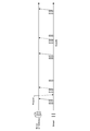
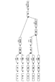
- FIG. 1 there is shown a conceptual diagram of a configuration of an overall system according to the present embodiment. As shown in FIG. 1, the entire system 1 includes a server 300, a plurality of gateways 200, and a plurality of sensors 100.
- the network N is configured to be able to communicate between the cloud (server 300) and the gateway 200, between the gateway 200 and the sensor 100, and between the cloud (server 300) and the sensor 100.
- the gateway 200 may have the function of the sensor 100.
- Network N is a generic name of the network of the present embodiment including the network N1 and the network N2.
- the physical layer and data link layer of the network N are not limited.
- a mobile phone communication network including an MNO (Mobile Network Operator) network, an MVNO (Mobile Virtual Network Operator) network), a network based on various wireless local area network standards, a short-range wireless communication (Bluetooth (registered) Trademark) can be used as the network of the present embodiment.
- a wide area network, a business network, a private network, or the like can be used as the network N.
- the gateway 200 has the same configuration as a general-purpose computer. That is, the gateway 200 includes a CPU (Central Processing Unit) 11, a ROM (Read Only Memory) 12, a RAM (Random Access Memory) 13, an input / output interface 15, and a bus 14 for connecting these to each other.
- a CPU Central Processing Unit
- ROM Read Only Memory
- RAM Random Access Memory
- the CPU 11 accesses the RAM 13 and the like as needed, and controls the entire block as a whole while performing various arithmetic processes.
- the ROM 12 is a non-volatile memory in which an OS (Operating System) executed by the CPU 11 and firmware such as programs and various parameters are fixedly stored.
- the RAM 13 is used as a work area for the CPU 11 and temporarily stores an OS, various applications being executed, and various data being processed.
- the CPU 11 loads a software program stored in the ROM 12 to configure a control unit of the apparatus.
- the display unit 16, the operation receiving unit 17, the storage unit 18, the communication unit 19, and the like are connected to the input / output interface 15.
- the display unit 16 is a display device using, for example, an LCD (Liquid Crystal Display), an OELD (Organic Electro-Luminescence Display), a CRT (Cathode Ray Tube), or the like.
- the operation receiving unit 17 is, for example, a pointing device such as a mouse, a keyboard, and other input devices.
- the display unit 16 and the operation receiving unit 17 may be integrated by a liquid crystal touch panel.
- the storage unit 18 is a non-volatile memory such as a hard disk drive (HDD), a solid state drive (SSD), and other solid-state memories.
- the storage unit 18 stores the OS, various applications, and various data.
- the communication unit 19 is various modules for wireless communication such as a NIC (Network Interface Card) and a wireless LAN.
- the communication unit 19 enables transmission and reception of data with another device of the present apparatus.
- the configuration shown in FIG. 2A is an example of the configuration of the gateway 200, and other elements may be added or some of them may be omitted.
- the server 300 and the sensor 100 may have the same configuration as the gateway 200. Other components may be added to the configuration of the server 300 and the sensor 100, or some of them may be omitted.
- FIG. 2B shows a configuration example of the sensor 100. Description of the parts common to FIG. 2A is omitted.
- the sensor 100 has a sensor unit 20 and a sensor unit 21. In this case, the sensor 100 capable of storing two types of sensing data is illustrated. Specific examples of the sensor unit 20 and the sensor unit 21 include, for example, a camera, a human sensor, and an antenna capable of evaluating the radio wave intensity and radio wave quality of wireless communication. However, this example does not limit the sensor 100.
- the plurality of gateways 200 are intermediate nodes located between the sensor 100 and the server 300, and have a multi-layer structure in which any one of the gateways 200 is located above another gateway 200. May be done.
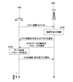
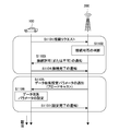
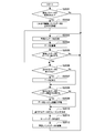
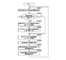
- the server 300 makes settings for the gateway 200 (1-1 in FIG. 3).
- the gateway 200 makes settings for the sensor 100 based on the settings made for the gateway 200 by the server 300 (1-2 in FIG. 3). This is the setting phase.
- the sensor 100 transmits the sensed information to the gateway 200.
- the gateway 200 collects information from the sensor 100 (2-1 in FIG. 3).
- the gateway 200 transmits the collected information or information obtained by processing the collected information to the server 300.
- the server 300 collects information from the gateway 200 (2-2 in FIG. 3). This is the operation phase.
- the server 300 performs analysis and the like based on the collected information and feeds it back to the resetting and control of the gateway 200 and the sensor 100 (3 and 4 in FIG. 3). This is the utilization phase.
- the setting of the sensor 100 may use the information on the setting transmitted from the server 300 to the gateway 200 as it is, or may be generated based on the setting received by the gateway 200 from the server 300.
- the setting parameters of the sensor 100 are provided from the server 300 in common.
- the server 300 directly sets the sensor 100 and that information is directly transmitted from the sensor 100 to the server 300. .
- Sensing data of the sensor 100 and the like are mostly handled in the application layer.
- the application layer only End-to-End is defined, and a node in the middle (intermediate node) is usually transparent.
- the gateway 200 which is an intermediate node, collects and processes sensing data of the sensor 100 in the operation phase.
- the gateway 200 reduces the network load.
- the base station that is the boundary between the wireless network and the wired network according to the present embodiment is used in consideration of the fact that the sensing data has high location dependency.
- the gateway 200 is advantageous, but is not limited to this configuration.
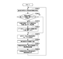
- Setting Phase 1.4.1. Overview of Setting Phase The setting phase is divided into two stages, a setting process from the server 300 to the gateway 200 and a setting process from the gateway 200 to the sensor 100.
- the server 300 sets to the sensor 100 which data items the sensor 100 should transmit to the server 300, in what manner (processing, no processing, etc.) and at what frequency. Is set for the gateway 200 of the intermediate node. This makes it possible to optimize data collection even when the network load fluctuates, such as when the number of sensors 100 increases.
- the server 300 sets the data items to be collected from the sensor 100 and the frequency for the gateway 200.
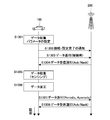
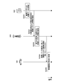
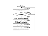
- the gateway 200 notifies the server 300 of its own location information (S401).
- the server 300 determines parameters for the gateway 200 that has notified the location information (S402).
- a notification of the parameter determined by the server 300, in this example, the data collection setting is sent (S403).
- the gateway 200 sets the data collection parameters for its own device (S404).
- the gateway 200 notifies the server 300 of the completion of the setting (S405).
- the server 300 specifies data pre-processing in the gateway 200 (base station) according to the data item of the collected data.
- the pre-processing include an averaging process, a compression process, and a combining process.
- the averaging process includes a process of averaging the collected data for each terminal and a process of averaging over the entire base station area beyond the terminal.
- the compression processing includes lossless compression and lossy compression.
- Lossy compression includes compression using a one-way hash function. In the present embodiment, compression is performed using a one-way hash function.
- the combining process includes a process of combining a plurality of collected data or compressed data into one or a small number of bundles.
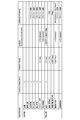
- FIG. 5 shows an outline of data items collected by the system 1. Shown here is an outline, which may be finer data items. Further, the data items are not limited to those illustrated in FIG.
- FIG. 6 is an explanatory diagram of the collection frequency shown in FIG.
- the data collected by the system 1, that is, the data collected by the server 300 includes information on the sensor 100 itself, processed data, and raw data.
- these collected data there are sufficient data to be collected only once when the sensor 100 is initially attached to the network N of the system 1, data to be collected periodically, and data to be collected non-periodically. is there.
- the period of data collected periodically may be divided into multiple stages such as short-term and long-term.
- the data collected non-periodically includes sensing data having a large data amount such as a moving image.
- the periodically collected data is sent from the sensor 100 to the server 300 as shown by a solid arrow in FIG.
- the data collected aperiodically is sent from the sensor 100 to the server 300 when there is a request from the server 300 or when the sensor 100 detects the occurrence of an event, as indicated by a dashed arrow in FIG.
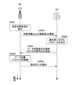
- the gateway 200 notifies the sensor 100 that has made the connection request of the setting parameter for data collection specified by the server 300.
- the gateway 200 may perform additional data collection settings in addition to the settings specified by the server 300.
- a setting contrary to the specification from the server 300 is not permitted. If the sensor 100 has already received the setting parameter once, the sensor 100 uses the setting parameter notified by the gateway 200 as the setting parameter for resetting.
- the sensor 100 requests connection to the gateway 200 as an initial attach to a network, such as when the power is turned on or when a communication function is turned on, when a certain gateway (base station) is connected to another gateway (base station). Station), or when moving from outside the service area to the service area.
- the occurrence of the handover mentioned here includes the start of the handover, the execution of the handover, and the completion of the handover. Since the gateway 200 transmits the setting parameter to the sensor 100 at the timing of receiving the connection request from the sensor 100, smooth information collection is promoted.
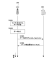
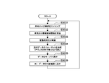
- the sensor 100 makes a connection request to the gateway 200 (S701).
- it is determined whether the gateway 200 permits the connection request (S702).
- the gateway 200 notifies the sensor 100 that has made the connection request of connection permission or non-permission (S703). Here, it is assumed that permission has been granted.
- the gateway 200 notifies the sensor 100 of the data collection setting parameter (S704).
- the sensor 100 sets data collection parameters for the own device (S705).
- the sensor 100 notifies the gateway 200 of the connection and the setting completion (S706).
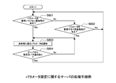
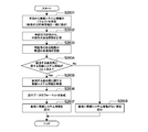
- FIGS. 8, 9 and 10 show examples of processing procedures of the CPU 11 as a control unit of each of the server 300, the gateway 200, and the sensor 100 regarding parameter setting.
- the server 300 first checks whether there is a gateway 200 (base station) for which no parameter is set (S801). Even when there is no such gateway 200, the server 300 checks whether or not there is a gateway 200 (base station) whose parameter should be changed (S802). If any one of such gateways 200 exists, the server 300 notifies the gateway 200 of the setting parameters (S803). If the setting completion packet is included in the setting parameter packet or the like, the process of the server 300 ends (S804).
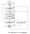
- the gateway 200 first checks whether or not the parameters of its own device have not been set (S901). If the parameters of the own device have been set (S901, No), the movement distance of the own device is detected (S907, described later).
- the gateway 200 If the parameters of the own device are not set (S901, Yes), the gateway 200 notifies the server 300 of the position information and the mobility information of the own device (S902). Subsequently, the gateway 200 confirms whether or not there is a parameter designation by the notification of the setting parameter from the server 300 as described in S803 of FIG. 8 (S903).
- the gateway 200 changes the setting parameter to the specified parameter (S904).
- the server 300 is notified of the setting completion (S905).
- the sensor 100 vehicle is notified of the parameter change (S906).
- the gateway 200 detects the moving distance and the like of the gateway 200 (own apparatus) (S907).
- the gateway 200 determines whether or not the moving distance or the like detected in S907 has exceeded a predetermined threshold (S908).
- the gateway 200 notifies the server 300 of new position information and the like of the gateway 200 (own apparatus) (S902).
- the gateway 200 continues to use the setting parameters specified by the server 300 (S909), and thereafter, the moving distance and the like. Is detected (S907), and the detected moving distance and the like are compared with the threshold (S908).
- the moving distance and the like in FIG. 9 include a position, a connected base station, a change in speed and acceleration, and the like.
- the predetermined threshold value in FIG. 9 is an absolute amount such as a detected moving distance, but in another embodiment, the relative change amount (difference) of the moving distance or the like is different. It may be a predetermined threshold.
- the sensor 100 first determines whether to connect (including reconnection) to the gateway 200 (base station) (S1001). Next, the sensor 100 notifies the gateway 200 of a connection request (S1002). Next, the sensor 100 determines whether or not a parameter has been designated from the server 300, and if a parameter has been designated, the sensor 100 changes the setting parameter to the designated parameter (S104). Next, the sensor 10 notifies the gateway 200, which is a base station, of the completion of the setting (S105).
- the sensor 100 checks whether the parameter specified by the current (after connection) gateway 200 has been set (S1006). If it has been set, the current parameter is used continuously (S1007). If not set, the current parameter is reset (S1008). The sensor 100 waits for the next parameter designation from the server 300 in any of the parameter setting (S1005), the continuous use of the parameter (S1007), and the parameter reset (S1008) (S1003).
- the sensor 100 When the sensor 100 resets the data collection parameters (S1008), the sensor 100 stops sending data to the gateway 200 (or the server 300). However, even in this case, the sensor 100 may continue collecting (such as sensing) data internally.
- Operation Phase 1.5.1. Sensor Data Collection Process The operation phase is divided into two stages: a data collection process from the sensor 100 to the gateway 200, and a data collection process from the gateway 200 to the server 300.
- the process of collecting data from the sensor 100 to the gateway 200 is divided into a process of establishing a connection (first stage) and a process of sensing and sending data (second stage).
- the sensor 100 in the first stage of the process of collecting data from the sensor 100 to the gateway 200, the sensor 100 establishes a connection with the gateway 200.
- the sensor 100 issues a connection request to the gateway 200 (S1101).
- the gateway 200 determines whether to permit connection to the sensor 100 that has issued the connection request (S1102).
- the gateway 200 notifies the sensor 100 of the determination result of the connection possibility (S1103). In this example, the connection is permitted, and the sensor 100 notifies the gateway 200 of the completion of the connection (S1104).
- the gateway 200 When the connection with the sensor 100 is established, the gateway 200 notifies the data collection setting parameters subsequently (S1105). This notification may be performed by a method of broadcasting to all the sensors 100 connected to the gateway 200 (S1105). Next, the sensor 100 sets the parameters for data collection notified from the gateway 200 to its own device (S1106). Further, the sensor 100 notifies the gateway 200 of the setting completion (S1107).
- the gateway 200 sets the setting parameters for each sensor 100 that has issued the connection request in S1105 (or the sensor 100 that has issued the connection request and has been permitted to connect). Send. That is, the gateway 200 transmits the setting parameters to the sensor 100 in a unicast system. When the gateway 200 transmits the setting parameters to the sensor 100 by the unicast method, the setting parameters suitable for the state and environment of each sensor 100 are applied to the sensor 100. When transmitting the setting parameter to the sensor 100, the gateway 200 transmits only the difference from the previously transmitted setting parameter to the sensor 100. Since the gateway 200 transmits only the difference, the amount of data flowing on the network can be suppressed.
- the gateway 200 may collectively notify the data collection parameters to the plurality of sensors 100 within the communication range of the gateway 200 in S1105. That is, the gateway 200 may transmit the setting parameters to the plurality of sensors 100 in a broadcast (or multicast, group cast) method. When the gateway 200 transmits the setting parameters to the sensors 100 by a broadcast method or the like, the setting parameters can be notified to a large number of sensors 100 by a small number of communication such as one time. The gateway 200 may notify the setting parameters periodically (for example, once every 10 minutes) by a broadcast method or the like regardless of the establishment of the connection with the sensor 100 (S1101 to S1104).
- the gateway 200 Since the setting parameters transmitted to the sensor 100 are a set of parameters including a plurality of setting parameters, the gateway 200 changes some of the setting parameters to the sensor 100 (or the connection request) that issued the connection request. Is issued and the connection is notified for each sensor 100), and another part of setting parameters such as the remaining setting parameters are collectively notified to a plurality of sensors 100 within the communication range of the gateway 200. You may.
- the gateway 200 transmits the setting parameters according to the type of the setting parameters.
- the communication system is selected from communication systems such as unicast, broadcast, multicast, and group cast.
- the gateway 200 transmits, for example, a setting parameter for collecting data such as a personal state of a driver of a moving object (vehicle or the like) by a unicast method transmitted for each sensor 100.
- the gateway 200 transmits a setting parameter for collecting data such as environmental information centered on the gateway 200 by a broadcast method which is transmitted to the sensors 100 under the gateway 200 at the same time.
- the communication unit 19 (or the CPU 11) of the gateway 200 transmits the setting parameters of the type to apply the individual setting to each sensor 100 to the sensor 100 by the unicast method, and sets the same setting to the unspecified number of sensors 100.
- a setting parameter of a type to which is applied to the sensor 100 by a broadcast method flexible distribution of the setting parameter becomes possible. Therefore, according to this configuration, it is possible to dynamically respond to a change in the load of the network or the server.
- FIG. 12 shows a specific example of sensing data (collected data) transmitted from the sensor 100 to the gateway 200.
- sensing data collected data
- the sensor 100 in the case where the sensor 100 is installed on a moving body such as a vehicle as in the present embodiment, for example, data on the state inside the vehicle (such as the number of occupants) and the state outside the vehicle (position data, speed, etc.) Data related to mobility, wireless communication environment, etc.) can be cited as sensing data.
- data items to be sent from the sensor 100 to the gateway 200, timing, additional processing, and the like are designated by setting parameters transmitted from the gateway 200 to the sensor 100.
- the timings that can be set include the time of network attachment, periodic, aperiodic, and the like.
- the sending timing in FIG. 12 is the sending timing set by the setting parameter, and the data collection itself may be performed at a more frequent timing.
- the data collection period is equal to or shorter than the setting in FIG. 12 (data transmission period ⁇ data sensing period), or the data collection frequency is equal or higher (data transmission period). (Frequency ⁇ data sensing frequency) is desirable.
- the sensor 100 performs data collection (sensing) and data transmission according to the setting parameters set in the setting phase.
- the sensor 100 performs data collection (sensing) (S1301). At this time, the sensor 100 re-applies the setting parameters to its own device as needed (S1301). Next, the sensor 100 connects to the gateway 200 and notifies the completion of the setting (S1302). Next, the sensor 100 sends the collected data (sensing data) to the gateway 200 (S1303). Next, the gateway 200 notifies the reception of the sensing data (S1304). This notification is performed irrespective of whether the reception is successful (Ack) or unsuccessful (Nack).
- the above processing in FIG. 13 is the case where the sensor 100 sends the sensing data simultaneously with the connection to the gateway 200.
- ⁇ ⁇ ⁇ Data may be processed in the vehicle between data collection (sensing) and data transmission.
- data processing include time averaging of collected data, coding of collected moving images, privacy protection (mosaicing a person), and the like.
- the sensor 100 When the sensor 100 processes (compresses, etc.) the sensing data in its own device, the sensor 100 performs data processing after collecting data (S1305) and then performs data processing (S1306). Subsequent processing (S1307, 1308) is the same as S1303, S1304.
- the sensor 100 discards the data collected so far when the setting parameters of the data collection change during the data collection or before the data transmission (between S1301 and S1303). It may be.
- FIG. 14 shows an example of a data collection processing procedure (sensor 100).
- the sensor 100 executes a series of handover processes (S1402), and changes the parameters of the sensor 100 (self apparatus) based on the setting parameters received from the gateway 200 newly connected by the handover. It is set (S1403).
- the setting parameters of the sensor 100 (own device) are updated at the timing of handover occurrence (including start of handover, execution of handover, completion of handover) caused by the movement of the sensor 100 installed in the moving body (vehicle, etc.).
- the sensor 100 can collect information using appropriate setting parameters immediately after entering the area where communication with the gateway 200 is valid.
- the sensor 100 skips the handover process and sets the parameters of the own device based on the setting parameters received from the gateway 200 (S1403).
- the sensor 100 determines whether the connection to the gateway 200 for the first time, that is, the transmission of data to be performed when the gateway 200 is initially attached, has been performed (S1404).
- the data transmitted when the sensor 100 first connects to the gateway 200 includes static information of the sensor 100 (own device) such as the specifications of the CPU 11 and the RAM 13 and the firmware version, the temperature of the CPU 11, the usage rate of the RAM 13, and the like. , Information about the environment of the sensor 100 (own device), such as dynamic information of the sensor 100 (own device) and sensing data. If the data to be transmitted at the time of the first connection to the gateway 200 has not been transmitted (S1404, No), the sensor 100 transmits the data to the gateway 200 (S1405).
- the sensor 100 determines whether the setting parameters distributed and transmitted by the gateway 200 have changed (S1406). Since the gateway 200 notifies the sensor 100 that the setting parameter has changed, the sensor 100 determines whether or not the setting parameter has changed based on the notification from the gateway 200. If the setting parameters have been changed (S1406, Yes), the sensor 100 discards the collected data that has not been sent to the gateway 200 yet (S1407), performs handover if necessary (S1402), and resets the parameters. (S1403).
- the sensor 100 collects (senses) data of the data items scheduled to be sent (S1408). Next, the sensor 100 continues sensing until the data transmission timing comes (S1409). When the data transmission timing has come (S1409, Yes), the sensor 100 determines whether to process the sensing data before data transmission (S1410). When processing the sensing data (S1410, Yes), the sensor 100 processes the collected sensing data (S1411). On the other hand, when the sensing data is not to be processed (S1410, No), the sensor 100 skips the processing of the collected sensing data.
- the sensor 100 checks whether or not a wireless resource for data transmission is allocated (S1412). If not (S1412, No), the sensor 100 requests the gateway 200 to allocate a wireless resource (S1412, No). S1413).
- the sensor 100 forms the format of the data to be sent (S1414), and sends the data to the gateway 200 using the allocated wireless resources (S1415).
- FIG. 15 shows an example of the data format formed in S1414. As shown in FIG. 15, the format of data sent from the sensor 100 is divided into a header and a payload, and a bundle of a plurality of (including a plurality of types) collected data can be stored.
- the sensor 100 downloads the setting parameters from the gateway 200 every time a handover occurs. Apply to your own device.
- the gateway 200 transmits the setting parameters in response to the setting parameter download request from the handover sensor 100.
- the gateway 200 may transmit the setting parameters using the handover occurrence information as an occurrence event.
- the detailed process of the process related to the transmission of the setting parameter is as described in the setting phase.
- Gateway Data Collection Process As shown in FIG. 16, in the data collection process from the gateway 200 to the server 300, the gateway 200 performs data transmission according to the setting parameters set from the server 300.
- the gateway 200 receives the sensing data from the sensor 100 (vehicle) (S1601), and processes the received data as needed (S1602). Next, the gateway 200 transmits the processed data (or non-processed data) to the server 300 at various timings such as periodic and aperiodic (S1603). Upon receiving this, the server 300 returns a data reception notification to the gateway 200 (S1604).
- the gateway 200 itself may perform data collection (sensing). In this case, the gateway 200 also has the function of the sensor 100.
- data processing is not indispensable, and the gateway 200 determines whether or not to perform data processing.
- data processing include, for example, data averaging, compression, and combination.
- the gateway 200 discriminates between data that is processed as data for each vehicle and data that is subjected to averaging processing in the base station coverage. I do.
- FIG. 17 shows data items with distinctions. As shown in FIG. 17, the gateway 200 specifies data items to be sent from the gateway 200 to the server 300, timing, additional processing, and the like.
- the gateway 200 compresses the data.
- compression using a one-way hash function may be performed.
- a hash value output obtained by inputting sensing data to the one-way hash function is data that is actually collected (transmitted or received).
- it is not necessary to collect the sensing data itself before compression (only the hash value may be collected).
- the gateway 200 performs compression using a one-way hash function as an example of processing, and a detailed data collection process of the gateway 200 will be described.
- compression using a one-way hash function is adopted as a solution.
- the loads on the devices and the cloud are reduced, and the traffic in the wireless section is reduced.
- a hash tree (hash tree) is constructed in the entire system 1 or a part of the system 1.
- the hash tree is generated for each gateway 200 (base station).
- the data collected by the sensor 100 is highly dependent on the location. Therefore, when the hash tree is generated for each gateway 200 (base station), that is, for each location, usability when using data is higher than when the hash tree is not generated for each location.
- the gateway 200 (base station) adds a header to the hash tree, and describes the information (position information) of the gateway 200 (base station) that has performed compression in the header.
- FIG. 18 shows an example of the hash tree. As illustrated, in each of the gateways 200 and the sensors 100, compression using a one-way hash function is performed again on the hash obtained by combining the hashes compressed in the subordinate gateway 200 or the sensor 100. A hash tree as shown in FIG. 18 is constructed.
- FIG. 18 shows an example of a hash data format.
- FIG. 20 is an example of a processing procedure of a data collection process of the gateway 200.
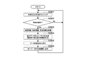
- the gateway 200 first checks whether or not the setting parameters distributed by the server 300 have been changed (S2001). When the setting parameter has been changed (S2001, Yes), the gateway 200 prepares to send the data received and accumulated from the sensor 100 up to this point (S2002).
- the gateway 200 receives data from the sensor 100 (vehicle) (S2003). Next, the gateway 200 accumulates the data (S2004), and waits for a timing for sending the accumulated data to the server 300 (S2005). Next, when the data transmission timing comes (S2005, Yes), the gateway 200 determines whether or not to process the data (excluding compression by a hash function) (S2006).
- the gateway 200 determines the necessity of the data processing (S2006) based on, first, the sensing data of the sensor 100 and, second, the data collection setting parameters set in the sensor 100 in the setting phase. .
- the gateway 200 determines what event (hereinafter, “occurrence event”) has occurred in the system 1 based on the sensing data of the sensor 100, and based on the determined occurrence event. Determine whether data processing is necessary.
- the events that occur include all events sensed by the sensor 100, and specifically include detection of an accident, movement of the sensor 100 (and a vehicle such as a vehicle on which it is installed), and occurrence of handover of the vehicle (handover). , Starting a handover, and completing a handover).
- the gateway 200 determines whether or not data processing is necessary according to the setting parameters of the sensor 100, particularly, the type of each data item. Whether each data item of the setting parameter is data for each vehicle or data for each base station is set (FIG. 17). Therefore, for example, the gateway 200 determines that data is processed for each vehicle, and is not processed for data of each base station.
- the gateway 200 as an intermediate node between the server 300 and the sensor 100 in the system 1 determines whether the processing of the sensing data is necessary. Therefore, the load does not concentrate on the server 300, and the server 300 only needs to transmit the setting parameter optimized according to the network load or the like to the intermediate node for each bundle of sensors. Data collection can be optimized.
- the gateway 200 processes the data based on the determination in S2006 (S2007).
- the gateway 200 determines whether to compress the data using a hash function (S2008). This is also performed based on the setting parameters to the gateway 200 sent from the server 300 in the setting phase, similarly to the determination in S2006.
- the gateway 200 compresses the data with a hash function based on the determination in S2008 (S2009).
- the gateway 200 forms the format of the data to be sent (FIG. 19) (S2010).
- the gateway 200 sends data to the server 300 in the formed data format (S2011).
- the gateway 200 discards the stored data (S2012).
- the data stored so far may be sent.
- a wired network since a wired network has more resources than a wireless network, a wired network may be sent without performing processing and compression when making a determination in S2006 or S2008.
- FIG. 21 is a procedure example of the data collection process (server 300).
- FIG. 22 is a diagram for explaining an outline of a method of reproducing data based on a hash tree in the server 300.
- the server 300 reads the header of the hash tree (S2101), and calculates the number Nwo of hashes to be solved (S2102). Next, the hash function used in the hash tree is grasped (S2103), and 0 is set to the work variable n (S2104). Thereafter, until n ⁇ N (S2105), decompression candidate data is generated (S2106), a hash of the decompression candidate data is generated (S2108), and the generated hash and the hash of data used in the hash tree are generated. The operation of comparing with the value (S2109) and searching for a match (S2110) is repeated.
- the process of ascertaining the hash function includes ascertaining the data size (hash size) before and after the hash function processing.
- the compression by the one-way hash function has a good compression ratio, thereby reducing the load on the network N and the server 300.
- FIG. 23 is a diagram illustrating an outline of a use phase.
- the server 300 analyzes the accumulated data of the wireless system as shown in FIG. 23 (S2301). As an analysis result, the server 300 outputs data as shown in FIG. 24, for example.
- FIG. 24 shows an example of wireless system environment information provided from the server 300.
- the server 300 provides a wireless system that may be used in an area corresponding to a base station and its communication quality (eg, throughput, network delay, etc.).
- the server 300 provides information about not only a single base station but also a plurality of base stations including the vicinity.
- the first method is a method of broadcasting from the gateway 200 to the sensor 100 in the area.
- the second method is a method in which the sensor 100 makes a request to the gateway 200.
- destination information of a vehicle on which the sensor 100 is installed may be sent together with the request, and the server 300 may provide information on a base station (gateway 200) around the route.
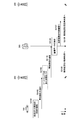
- the sensor 100 requests wireless system information from the base station (gateway 200) (S2501). At this time, the destination information of the vehicle is sent to one book.
- the sensor 100 extracts wireless system information on the target base station according to the possibility of handover (S2503 to S2505) (S2506, S2507). Then, it is checked whether or not the wireless system currently turned off in the area of the target base station is operating in its own device (S2508). If there is such a function, the function is turned on (S2509). Conversely, if there is a wireless system that is unlikely to operate in the area of the target base station, it is turned off unless it is fatal (S2510 to S2512).
- the server 300 upon receiving a request for wireless system information to which destination information is also attached from the vehicle (sensor 100) (S2601), calculates a possible route from the destination of the vehicle (S2602), The base station (gateway 200) around the possible route is grasped (S2603). Next, the server 300 determines whether there is one or more pieces of wireless system information on the corresponding base station (S2604). If there is, the wireless system information about the corresponding base station is prepared (S2605), formed into a predetermined format (S2606), and sent (S2607). If there is no wireless system information, the fact is sent to the vehicle (S2608).
- the sensor 100 can set a wireless system that has been optimized in advance by using wireless system information (such as radio wave intensity) accumulated by the other sensors 100.
- wireless system information such as radio wave intensity
- the state (radio wave intensity and the like) of various wireless communication environments of an in-vehicle device is assumed as an example of collected data.
- the present technology can take various embodiments.
- the second embodiment discloses an example in which sensing data is utilized when an accident event occurs using the same system and configuration as the first embodiment.
- the “accident event” in the second embodiment refers to an accident or the like, as described in the first embodiment, the “occurrence event” in the entirety of the present technology indicates that a handover has occurred in a lower node, the sensor 100 (or The movement of the vehicle on which it is installed) occurs.
- the accident event is an example of an occurrence event.
- FIG. 27 is a diagram for describing an outline of the overall operation of the second embodiment.
- the sensor 100 when detecting an accident in itself or in the vicinity (S2701), the sensor 100 transmits a notice of accident detection to the nearby gateway 200 (S2702).
- the gateway 200 determines the notification to the server 300 using the notification of the accident detection (S2703).
- the occurrence of an accident is detected by the sensor unit 20 or the sensor unit 21 provided in the sensor 100.
- the sensing data is obtained as a moving image.
- the gateway 200 has a monitoring camera or the like as a sensor device, the gateway 200 can also acquire a moving image as sensing data.
- the gateway 200 notifies the server 300 of the accident detection (S2704). At the same time, the gateway 200 performs data analysis, and sends and sends the analysis result to the sending target gateway 200 such as a base station affected by the accident (S2705).
- the server 300 receives the notification of the accident detection, accumulates the attached sensing data, and performs analysis based on the accumulated data (S2706).
- the sensing by the gateway 200 and the sending of the sensing data to the server 300 may be continuously performed, and such sensing and the sending thereof may be performed by a plurality of gateways 200.
- the server 300 sends and sends the analysis result to an external organization such as the police or fire department (S2707).
- the server 300 sends and sends the analysis result to the sending target gateway 200 such as a base station affected by the accident (S2708).
- FIGS. 28, 29, and 30 show an example of a processing procedure of the CPU 11 functioning as a control unit of each of the server 300, the gateway 200, and the sensor 100 in the present embodiment.
- the sensor 100 performs sensing on its own device and its surroundings (S2801).
- the sensor 100 transmits the position information, the time information, and the accident information to another device (including the server 300, the gateway 200, the other sensors 100, and an external organization). For this purpose, these pieces of information are prepared (S2803).
- the sensor 100 forms the format of the transmission data (S2804). At that time, the sensor 100 may form a format to which information indicating an emergency is added.
- the sensor 100 sends the formatted sensing data to the gateway 200 of the upper node (S2805). Before or after this, the same data may be sent to an external organization (S2806).
- the gateway 200 performs sensing on its own device and its surroundings (S2901). S2901 may be performed when the gateway 200 also has the function of the sensor 100. Next, the gateway 200 receives information (position information, time information, and accident information) on the accident detected from the sensor 100 (vehicle) (S2902). The gateway 200 may receive the accident detection information from each of the sensors 100 in some cases.
- the gateway 200 determines whether or not accident detection information has been received from a predetermined number or more of different sensors 100 (vehicles) at similar positions and similar times (S2903). When such a condition is not satisfied (S2903, No), the gateway 200 determines that the notified accident is an error or erroneous detection, except when the gateway 200 detects an accident even in its own device (S2904, Yes). It is determined (S2904, No).
- the gateway 200 determines that the accident occurrence position is within a predetermined range based on the position information included in the accident detection information (similar position)
- the gateway 200 determines the accident occurrence time based on the time information included in the accident detection information. If it is within a predetermined range (similar time), if there is a plurality of items that can be judged as accident detection information for the same accident (S2903, Yes), and if the own device also detects an accident (S2904, Yes), Judge that the probability of accident occurrence is high.
- the gateway 200 can appropriately remove the erroneous detection and perform processing.
- the gateway 200 prepares the position information, the time information, and the accident information in order to transmit the information to other devices (including the server 300, the gateway 200 of the upper node, and the external organization) (S2905).
- the gateway 200 forms a format of the transmission data (S2906).
- the gateway 200 may form a format to which information indicating an emergency is added.
- the gateway 200 sends the formatted sensing data to the server 300 (S2907). Before or after this, the same data may be sent to an external organization (S2908).
- the server 300 receives the accident detection information from the gateway 200 (base station) and / or the sensor 100 (vehicle) (S3001). Next, the server 300 determines whether there is data related to the vehicle involved in the accident related to the notification target (S3002). If there is, the server 300 refers to data close to the time of the target accident for the target vehicle (S3003). Next, the server 300 analyzes information (number of people, attributes, and the like) regarding a person from the data (S3004).
- the server 300 forms the format of the transmission data and the analysis result of S3004 (S3005).
- the server 300 sends the formatted analysis result to an external organization (S3006).
- the server 300 prepares accident information for neighboring base stations including the target base station related to the gateway 200 (base station) that sent the accident detection information (S3007).
- the server 300 sends the accident information to the target base station and the neighboring base stations (S3008).
- an accident event is detected in the processing from S2902 to S2904.
- An accident event is an example of an occurrence event.
- the CPU 11 that functions as the control unit of the gateway 200 does not process the setting parameters of its own device into the sensing data so that the sensing data can be used for real-time processing. Make settings. Then, the CPU 11 determines that substantial processing of the data in the gateway 200 is not necessary based on the setting.
- the gateway 200 does not perform compression using a hash function that takes time to decompress. Although not limited, the gateway 200 continues to collect data without performing processing such as compression, and continues to transmit the collected data to the server 300 or the like. Thereby, the information in the vehicle involved in the accident can be used immediately. After the data is collected by the server 300, after a predetermined time has elapsed, the data may be compressed by the server 300 to save storage.
- the gateway 200 determines whether the sensing data needs to be processed in accordance with an event (such as an accident) indicated by the sensing data.
- an event such as an accident
- the sensing data is not compressed. Therefore, according to the present embodiment, the accuracy of sensing data does not decrease in an important situation such as occurrence of a traffic accident. Further, according to the present embodiment, since the characteristics of the vehicle, the number of passengers, and the characteristics of the person can be collected, the scale of the fire truck and the ambulance rushing to the accident site can be appropriately adjusted.
- the gateway 200 may determine whether the real-time processing is necessary according to the sensing data. For example, if the sensing data is data that loses its value if uploaded to the server 300 later, data for live broadcasting, or a moving image of an accident or disaster, the gateway 200 determines that it is necessary to perform real-time processing. When the gateway 200 determines that it is necessary to perform real-time processing, the gateway 200 uploads the data to the server 300 without processing the data every time the sensor 100 uploads the sensing data. Each time the server 300 receives the sensing data, the server 300 performs a process on the sensing data.
- the notification to the server is determined using the sensing data (S2703).
- the gateway 200 may operate so as to pass the processing of processing the sensing data. An example in this case will be described below as a third embodiment.
- FIG. 31 is a diagram for explaining an outline of the overall operation of the third embodiment.
- the sensor 100 detects an accident at or near itself (S3101)
- the sensor 100 transmits a notification of the accident detection to the nearby gateway 200 (S3102).
- the gateway 200 determines whether or not to perform the processing in the gateway 200 based on the information indicating the urgency included in the notification of the accident detection (S3103). However, in the present embodiment, it is determined that “no processing” is performed (S3103).
- the gateway 200 notifies the server 300 of the accident detection (S3104). At the same time, the gateway 200 performs data analysis, and transmits and transmits the analysis result to the transmission target gateway 200 such as a base station affected by the accident (S3105).
- the server 300 receives the notification of the accident detection, accumulates the attached sensing data, and performs analysis based on the accumulated data (S3106).
- the sensing by the gateway 200 and the sending of the sensing data to the server 300 may be continuously performed, and such sensing and the sending thereof may be performed by a plurality of gateways 200.
- the server 300 sends and sends the analysis result to an external organization such as the police or fire department (S3107).
- the server 300 sends and sends the analysis result to the sending target gateway 200 such as a base station affected by the accident (S3108).
- FIGS. 32, 33, and 34 show an example of a processing procedure of the CPU 11 functioning as a control unit of each of the server 300, the gateway 200, and the sensor 100 in the present embodiment.
- the sensor 100 performs sensing on its own device and its surroundings (S3201).
- the sensor 100 transmits the position information, the time information, and the accident information to another device (including the server 300, the gateway 200, the other sensor 100, and an external organization). In order to do so, these pieces of information are prepared (S3203).
- the sensor 100 forms a format of the transmission data (S3204). At this time, the sensor 100 forms a format to which information indicating an emergency is given.
- the sensor 100 sends the formatted sensing data to the gateway 200 of the upper node (S3205). Before or after this, the same data may be sent to an external organization (S3206).
- the gateway 200 performs sensing on its own device and its surroundings (S3301). Step S3301 may be performed when the gateway 200 also has the function of the sensor 100. Next, the gateway 200 receives information (position information, time information, and accident information) on the accident detected from the sensor 100 (vehicle) (S3302). The gateway 200 may receive the accident detection information from each of the sensors 100 in some cases.
- the gateway 200 determines that an emergency response is necessary based on the emergency information included in the accident detection information (S3303). Unlike the second embodiment, the gateway 200 determines here not to perform processing such as data analysis, compression, and averaging.
- the gateway 200 forms a format of the transmission data in order to transmit the position information, the time information, and the accident information to other devices (including the server 300, the gateway 200 of the upper node, and an external organization) (S3304).
- the gateway 200 may form a format to which information indicating an emergency is added.
- the gateway 200 does not substantially process the data sent from the sensor 100, but performs data processing such as changing the destination address in the data in the format formation in S3304.
- the gateway 200 sends the formatted sensing data to the server 300 (S3305). Before or after this, the same data may be sent to an external organization (S3306).
- the server 300 receives the accident detection information from the gateway 200 (base station) and / or the sensor 100 (vehicle) (S3301). Next, the server 300 determines whether there is data on the vehicle involved in the accident related to the notification target (S3302). If there is, the server 300 refers to data close to the time of the target accident for the target vehicle (S3403). Next, the server 300 analyzes information about the person (number of people, attribute, etc.) from the data (S3404).
- the server 300 forms the format of the transmission data and the analysis result of S3004 (S3405).
- the server 300 sends the formatted analysis result to an external organization (S3406).
- the server 300 prepares accident information for nearby base stations including the target base station related to the gateway 200 (base station) that sent the accident detection information (S3407).
- the server 300 sends the accident information to the target base station and the neighboring base stations (S3408).
- collection is performed without performing compression using a hash function that takes a long time to decompress. Thereby, the information in the vehicle involved in the accident can be used immediately.
- the data After the data is collected by the server 300, after a predetermined time has elapsed, the data may be compressed by the server 300 to save storage.
- the gateway 200 it is determined that the gateway 200 is in an emergency and the information is transmitted to the server 300 without processing the data. Can be.
- the gateway 200 does not move.
- embodiments of the gateway 200 are not limited to those that do not move, and may include a mobile base station and a portable base station. It is also conceivable to use a so-called tethering technique for the gateway 200. Therefore, a case where the gateway 200 moves will be disclosed below as a fourth embodiment.
- FIG. 35 is a diagram (part 1) for explaining the setting phase in the present embodiment.
- the gateway 200 detects the mobility of its own device as needed (S3501). Examples of the mobility mentioned here include a change amount of an absolute position, a speed, and the like. When the mobility exceeds a predetermined threshold, the gateway 200 notifies the server 300 of the position information and the mobility (S3502).
- the server 300 determines parameters for the gateway 200 that has notified the location information (S3503).
- a notification of a parameter determined by the server 300, in this example, data collection setting is performed (S3504).
- the server 300 may notify the moving gateway 200 of the stop of data collection.
- the gateway 200 sets the data collection parameters for its own device (S3505).
- the gateway 200 notifies the server 300 of the completion of the setting (S3506).
- the gateway 200 when a movement equal to or more than a predetermined threshold occurs, the gateway 200 notifies the server 300 of the movement.
- the server 300 notifies the moved gateway 200 that the data collection setting is to be updated. This makes it possible to appropriately set the setting parameters even when the gateway 200 itself moves in the system 1.
- the server 300 may be configured such that when the base station moves, the reliability (stability) of data collected there is considered to be low.
- FIG. 36 is a diagram (part 2) for describing the setting phase in the present embodiment.
- the movable gateway 200 receives the notification of the setting change from the server as it moves (S3601). Next, the gateway 200 changes the data collection setting (S3602). Next, the gateway 200 notifies and transmits the data collection setting parameters to the sensor 100 (S3603). The sensor 100 sets the data collection parameters for its own device (S3604). The sensor 100 notifies the gateway 200 of the completion of the setting (S3605).
- the base station (gateway 200) notifies the vehicle (sensor 100) that has made the connection request of the data collection parameter specified by the server 300.
- the base station (gateway 200) may perform additional data collection settings in addition to the settings specified by the server 300.
- a setting contrary to the specification from the server 300 is not permitted.
- only the difference from the previous time may be notified.
- the timing of changing the parameter setting for data collection in the gateway 200 is set when the setting parameter is designated from the server 300.
- the present technology is not limited to this.
- An embodiment in which the gateway 200 changes (re-sets) the parameter setting of data collection according to a change in the number of subordinate sensors 100 will be disclosed as a fifth embodiment below.
- FIG. 37 shows an example of a processing procedure of the gateway 200 in the present embodiment.
- the gateway 200 detects the number or density of the subordinate vehicles (sensors 100) (S3701).
- the gateway 200 determines whether it is necessary to change the parameter according to the change in the number or density of the detected vehicles (S3702). If it is determined that it is not necessary, the gateway 200 continues to use the current parameter as the setting parameter used by the sensor 100 (S3708).
- the gateway 200 requests the server 300 to re-specify the parameters (S3703).
- the gateway 200 changes to the specified parameter (S3705).
- the gateway 200 notifies the server 300 of the completion of the setting (S3706).
- the gateway 200 notifies each of the subordinate sensors 100 of the parameter change (S3707).
- the number of subordinate sensors 100 is not limited, but may be the number of sensors 100 connected to the gateway 200.
- the density of the subordinate sensors 100 is not limited, but may be the number of the sensors 100 per unit area of the communicable area of the gateway 200.
- the gateway 200 determines the necessity of changing the parameter according to a change in the number or density of the detected sensors 100 (vehicles). Specifically, the gateway 200 determines whether the number or density of the detected sensors 100 (vehicles) exceeds a predetermined threshold, or that the rate of increase in the number or density of the detected sensors 100 (vehicles) is equal to the predetermined increase rate. If the threshold is exceeded, it is determined that the parameter needs to be changed.
- the CPU 11 functioning as a control unit of the gateway 200 regards a change in the movement state of the sensor 100 as an occurrence event, and redesignates the setting parameters of the subordinate sensor 100 according to the occurrence event.
- the CPU 11 may switch whether or not the processing of the sensing data in the own apparatus is required (performs / does not perform the processing).
- the frequency of data collection may be reduced. Further, when the number of vehicles decreases, the frequency of data collection may be increased. With this configuration, it is possible to flexibly cope with a predicted load on a network and resources.
- the information collection is performed immediately in response to a change in the moving state of the moving body (including a movement of a predetermined distance or more, a movement of a predetermined speed or more, and a change in the number of sensors in a sparse or dense state). become.
- the flowchart of FIG. 37 is an example in which the gateway 200 requests the server 300 to change (re-set) the data collection parameter when the number of vehicles changes, but the present technology is applied to this embodiment. It is not limited to. As another example, the gateway 200 may change (re-set) the data collection parameters of the vehicles under its control at the discretion of the gateway 200 without making a request to the server 300. In this case, autonomous processing of the gateway 200 is performed, and the load on the server 300 is reduced.
- the present technology is not limited to the above embodiments, and various modified embodiments are possible.
- the lower node of the gateway 200 and the sensor 100 as the sensor device of the system 1 are mounted on a vehicle (mobile body).
- the present technology is not limited to this. Needless to say.
- the sensor 100 may take the form of a monitoring camera, for example.
- the sensor 100 does not move, but a moving image can be collected as sensing data.
- the sensor 100 sequentially compresses the moving image, transmits only the picture frame of the compressed moving image to the gateway 200, and determines whether or not the processing is necessary based on the picture frame received by the gateway 200. can do.
- the gateway 200 may detect a person in the picture frame by image processing and transmit only information on the number of people to the server 300.
- the gateway 200 detects a suspicious person by the same image processing and if such detections are consecutive from the sensing data sent from the sensor 100 of a predetermined number and / or density, it is determined that the processing is unnecessary. Then, the sensing data from the sensor 100 may be transmitted to the server 300 without processing.
- a system for monitoring the congestion state of a passage or the like in a normal state can be obtained, and a system that automatically switches to a system for monitoring a suspicious person in an emergency can be realized.
- the present technology is not limited to the above embodiments, and can be implemented by variously modifying the above embodiments.
- the information processing disclosed above can be provided by a software program.
- a mode of providing the program may be provided by a recording medium irrespective of magnetic or optical, or may be provided by being downloaded through a telecommunication line.
- An information processing apparatus configured to mutually communicate with a server and a sensor via a network, A communication unit that transmits a setting parameter of the sensor to the sensor, receives sensing data of the sensor sensed based on the setting parameter, and transmits the sensing data to the server.
- An information processing apparatus comprising: a control unit configured to determine whether processing of the sensing data is necessary before transmitting the sensing data received from the sensor to the server.
- the information processing apparatus according to (1) or (2), The information processing device, wherein, when receiving a connection request from the sensor to the information processing device, the communication unit transmits the setting parameter for initial setting or resetting to the sensor.
- the sensor is a plurality
- the information processing device wherein the control unit updates the setting parameter according to a change in the number or density of a plurality of moving objects on which the sensors are installed.
- the information processing apparatus selects a method of transmitting the setting parameter to the sensor from a transmission method including at least a unicast method and a broadcast method according to a type of the setting parameter.
- the information processing apparatus according to any one of (1) to (6), The information processing device, wherein the control unit compresses the sensing data using a hash function when processing the sensing data.
- System 11 CPU 12 ... ROM 13 ... RAM Reference Signs List 15 input / output interface 16 display unit 17 operation receiving unit 18 storage unit 19 communication unit 100 sensor 200 gateway 300 server
Landscapes
- Engineering & Computer Science (AREA)
- Computer Networks & Wireless Communication (AREA)
- Signal Processing (AREA)
- Multimedia (AREA)
- Mobile Radio Communication Systems (AREA)
Abstract
ネットワーク負荷に動的に対応してデータ収集を最適化する。 本技術の情報処理装置(ゲートウェイ)は、サーバ及びセンサとネットワークを介して相互に通信するように構成される。上記情報処理装置は、通信部(通信部19)と制御部(CPU11)を具備する。上記通信部は、上記センサの設定パラメータを上記センサに送信し、上記設定パラメータに基づいてセンシングされた上記センサのセンシングデータを受信して上記サーバへ送信する。上記制御部は、上記センサから受信した上記センシングデータの上記サーバへの送信前に当該センシングデータの加工の要否を判断する(S2006)。
Description
本技術は、情報処理装置、情報処理方法及びプログラムに関する。
特許文献1には、例えば事故などのイベントが発生した場合、車載デバイスからサーバへ画像データが送付されるという、いわゆる「イベントドリブン型」の処理が記載されている。
特許文献2と特許文献3には、プロキシサーバの技術分野において、ハッシュインデックスを利用することによって、キャッシュへの高速アクセスを行うプロキシサーバについて記載されている。
「モノのインターネット」(IoT: Internet of Things)と呼ばれるシステムにおいては、膨大な量のノードが末端デバイスとしてネットワークに接続することが予想されている。IoTはデータの収集に適している。しかしながら、IoTの実装に、例えば上記特許文献1のようなシステムの構成を採用した場合、車載デバイスとサーバの間に中間処理がない。そのため、ノードが増えた場合にネットワークへの負荷が大きく、イベント発生時に急激にデータトラフィックが増加するという問題点がある。
以上のような事情に鑑みてなされた本技術の目的は、ネットワーク負荷に動的に対応してデータ収集を最適化する情報処理装置、情報処理方法及びプログラムを提供することにある。
上記目的を達成する本技術の一態様は、情報処理装置である。
上記情報処理装置は、サーバ及びセンサとネットワークを介して相互に通信するように構成される。
上記情報処理装置は、通信部と制御部を具備する。
上記通信部は、上記センサの設定パラメータを上記センサに送信し、上記設定パラメータに基づいてセンシングされた上記センサのセンシングデータを受信して上記サーバへ送信する。
上記制御部は、上記センサから受信した上記センシングデータの上記サーバへの送信前に当該センシングデータの加工の要否を判断する。
上記情報処理装置は、サーバ及びセンサとネットワークを介して相互に通信するように構成される。
上記情報処理装置は、通信部と制御部を具備する。
上記通信部は、上記センサの設定パラメータを上記センサに送信し、上記設定パラメータに基づいてセンシングされた上記センサのセンシングデータを受信して上記サーバへ送信する。
上記制御部は、上記センサから受信した上記センシングデータの上記サーバへの送信前に当該センシングデータの加工の要否を判断する。
上記情報処理装置によれば、サーバ、情報処理装置、センサを含むシステムにおける中間ノードとしての情報処理装置が、センシングデータの加工の要否を判断し、センシングデータの加工にかかる負荷がサーバに集中しないため、ネットワーク負荷に動的に対応してデータ収集を最適化することができる。
上記情報処理装置においては、上記制御部が、上記センシングデータに応じて上記センシングデータの上記サーバへの送信前の加工の要否を判断する構成であってもよい。
上記構成によれば、センシングデータに応じた情報や状況(限定するものではないが、外気温や電波強度といった情報や、交通事故発生といった状況など)に基づいてセンシングデータの圧縮や平均化等の加工の要否が判断されるため、重要な状況においてセンシングデータの精度が低下しない。
上記情報処理装置においては、上記通信部が、上記センサから接続リクエストを受信したときに、初期設定用又は再設定用の上記設定パラメータを上記センサに送信する構成であってもよい。
上記構成によれば、上記情報処理装置が、上記センサからのハンドオーバ等の接続リクエストを受信タイミングで設定パラメータを上記センサに送信するため、円滑な情報収集が促進される。
上記情報処理装置においては、上記センサが、複数であって、上記制御部が、上記センサが設置される複数の移動体の個数又は密度の変化に応じて前記設定パラメータを更新するする構成であってもよい。
上記構成によれば、上記移動体に設置されたセンサの数や、その疎密状態の変動に即応した情報収集が可能になる。
上記情報処理装置においては、上記通信部が、上記設定パラメータの種類に応じて、上記設定パラメータを上記センサに送信する方式を少なくともユニキャスト方式とブロードキャスト方式を含む送信方式の中から選択する構成であってもよい。
上記構成によれば、設定パラメータの種類に応じて、上記情報処理装置に接続する多くのセンサに同じパラメータを適用させたり、各センサに個別のパラメータを適用させたりすることが可能になる。これにより、柔軟な設定パラメータの配布が可能になり、ネットワークやサーバの負荷の変動への動的な対応も可能になる。
上記情報処理装置においては、上記制御部が、上記センシングデータを加工する場合に、上記センシングデータをハッシュ関数により圧縮する構成であってもよい。
上記構成によれば、一方向ハッシュ関数によりセンシングデータが効率よく圧縮されるので、ネットワークやサーバにかかる負荷が下がる。
上記目的を達成する本技術の別の一態様は、サーバ及びセンサとネットワークを介して相互に通信するように情報処理装置を構成し、上記センサの設定パラメータを上記センサに送信し、上記設定パラメータに基づいてセンシングされた上記センサのセンシングデータを受信し、上記センサから受信した上記センシングデータの加工の要否を判断し、上記センシングデータを上記サーバへ送信する情報処理方法である。
上記目的を達成する本技術の別の一態様は、コンピュータに、サーバ及びセンサとネットワークを介して相互に通信するように上記コンピュータを構成するステップと、上記センサの設定パラメータを上記センサに送信するステップと、上記設定パラメータに基づいてセンシングされた上記センサのセンシングデータを受信するステップと、上記センサから受信した上記センシングデータの加工の要否を判断するステップと、上記センシングデータを上記サーバへ送信するステップを実行させるためのプログラムである。
以上のように、本技術によれば、ネットワーク負荷に動的に対応してデータ収集を最適化する情報処理装置、情報処理方法及びプログラムの提供が可能になる。
なお、ここに記載された効果は必ずしも限定されるものではなく、本開示中に記載されたいずれかの効果であってもよい。
なお、ここに記載された効果は必ずしも限定されるものではなく、本開示中に記載されたいずれかの効果であってもよい。
以下、本技術に係る実施形態を、図面を参照しながら説明する。
説明は次の順番で行うものとする。
1.第1の実施形態
1.1.システム全体
1.2.サーバ、ゲートウェイ、センサの構成
1.3.全体の動作の説明
1.4.設定フェイズ
1.4.1.設定フェイズの概要
1.4.2.設定フェイズの詳細
1.5.運用フェイズ
1.5.1.センサのデータ収集プロセス
1.5.2.ゲートウェイのデータ収集プロセス
1.5.3.サーバのデータ収集プロセス
1.6.活用フェイズ
2.第2の実施形態
3.第3の実施形態
4.第4の実施形態
5.第5の実施形態
6.他の実施形態
7.付記
説明は次の順番で行うものとする。
1.第1の実施形態
1.1.システム全体
1.2.サーバ、ゲートウェイ、センサの構成
1.3.全体の動作の説明
1.4.設定フェイズ
1.4.1.設定フェイズの概要
1.4.2.設定フェイズの詳細
1.5.運用フェイズ
1.5.1.センサのデータ収集プロセス
1.5.2.ゲートウェイのデータ収集プロセス
1.5.3.サーバのデータ収集プロセス
1.6.活用フェイズ
2.第2の実施形態
3.第3の実施形態
4.第4の実施形態
5.第5の実施形態
6.他の実施形態
7.付記
1.第1の実施形態
本実施形態ではセンサの一例として、IoTシステムにおけるIoTデバイスを示し、IoTデバイスのさらにその一例として車載型センサ(車載デバイス)を示すが、センサが本例示に限定されるものではない。
本実施形態では情報処理装置の一例として、無線データ通信システムにおける基地局(以下、主として「ゲートウェイ」と呼ぶ)を示すが、情報処理装置が本例示に限定されるものではない。
本実施形態ではサーバの一例として、物理的に複数のサーバ群により構成されるいわゆるクラウドサーバを示すが、サーバが本例示に限定されるものではない。
本実施形態では収集データの一例として、車載デバイスの各種無線通信環境の状態(電波強度等)を想定するが、本技術が本例に限定されるものではない。
1.1.システム全体
図1を参照すると、本実施形態に係るシステム全体の構成の概念図が示されている。図1に示すように、システム1の全体は、サーバ300、複数のゲートウェイ200、複数のセンサ100を含む。
図1を参照すると、本実施形態に係るシステム全体の構成の概念図が示されている。図1に示すように、システム1の全体は、サーバ300、複数のゲートウェイ200、複数のセンサ100を含む。
ネットワークNは、クラウド(サーバ300)とゲートウェイ200、ゲートウェイ200とセンサ100、クラウド(サーバ300)とセンサ100の間を相互に通信できるように構成される。なお、ゲートウェイ200は、センサ100の機能を兼ね備えていてもよい。
ネットワークNはネットワークN1とネットワークN2を含む本実施形態のネットワークの総称である。ネットワークNの物理層やデータリンク層などは限定されない。一例を挙げると、インターネット、携帯電話通信網(MNO(Mobile Network Operator)網、MVNO(Mobile Virtual Network Operator)網を含む)、種々の無線ローカルエリアネットワーク規格によるネットワーク、近距離無線通信(Bluetooth(登録商標)を含む)などが本実施形態のネットワークとして利用できる。ネットワークNは、広域ネットワーク、事業者ネットワーク、プライベートネットワークなどが利用できる。
システム1に類似する構成をとるシステムにおいては、センサの数が増大すると、ネットワークの輻輳が生じたり、センサからデータを得たゲートウェイやサーバの処理負荷がかかったりするという問題が生じる可能性があった。
1.2.サーバ、ゲートウェイ、センサの構成
図2を参照すると、本実施形態にかかるゲートウェイ等の構成の概念図が示されている。図2(a)に示すように、ゲートウェイ200は、汎用のコンピュータと同様の構成を備える。すなわち、ゲートウェイ200は、CPU(Central Processing Unit)11、ROM(Read Only Memory)12、RAM(Random Access Memory)13、入出力インタフェース15、及び、これらを互いに接続するバス14を備える。
図2を参照すると、本実施形態にかかるゲートウェイ等の構成の概念図が示されている。図2(a)に示すように、ゲートウェイ200は、汎用のコンピュータと同様の構成を備える。すなわち、ゲートウェイ200は、CPU(Central Processing Unit)11、ROM(Read Only Memory)12、RAM(Random Access Memory)13、入出力インタフェース15、及び、これらを互いに接続するバス14を備える。
CPU11は、必要に応じてRAM13等に適宜アクセスし、各種演算処理を行いながら各ブロック全体を統括的に制御する。ROM12は、CPU11に実行させるOS(Operating System)、プログラムや各種パラメータなどのファームウェアが固定的に記憶されている不揮発性のメモリである。RAM13は、CPU11の作業用領域等として用いられ、OS、実行中の各種アプリケーション、処理中の各種データを一時的に保持する。
また、CPU11はROM12に記憶されているソフトウェアプログラムをロードすることにより本装置の制御部を構成する。
また、CPU11はROM12に記憶されているソフトウェアプログラムをロードすることにより本装置の制御部を構成する。
入出力インタフェース15には、表示部16、操作受付部17、記憶部18、通信部19等が接続される。表示部16は、例えばLCD(Liquid Crystal Display)、OELD(Organic Electro-Luminescence Display)、CRT(Cathode Ray Tube)等を用いた表示デバイスである。操作受付部17は、例えばマウス等のポインティングデバイス、キーボード、その他の入力装置である。なお、表示部16と操作受付部17を液晶タッチパネルにより一つにまとめてもよい。
記憶部18は、例えばHDD(Hard Disk Drive)や、フラッシュメモリ(SSD;Solid State Drive)、その他の固体メモリ等の不揮発性メモリである。当該記憶部18には、上記OSや各種アプリケーション、各種データが記憶される。
通信部19は、例えばNIC(Network Interface Card)や無線LAN等の無線通信用の各種モジュールである。通信部19により本装置の他装置とのデータの送受信が可能になる。
図2(a)に示す構成はゲートウェイ200の構成の一例であり、他の要素が追加されてもよく、また、一部が省略されてもよい。サーバ300とセンサ100もゲートウェイ200と同様の構成とすることができる。サーバ300とセンサ100の構成も、他の要素が追加されてもよく、また、一部が省略されてもよい。
図2(b)にセンサ100の構成例が示されている。図2(a)と共通する部分の説明は省略する。センサ100はセンサ部20とセンサ部21を有する。この場合はセンシングデータを2種類蓄積できるセンサ100を例示している。センサ部20とセンサ部21の具体例としては例えば、カメラや人感センサ、無線通信の電波強度や電波品質を評価可能なアンテナ等が挙げられる。しかしながら本例示はセンサ100を限定するものではない。
1.3.全体の動作の説明
図3を参照すると、本実施形態に係るシステム1の全体の動作の概要を説明するための概念図が示されている。図3に示すように、複数のゲートウェイ200はセンサ100とサーバ300の中間に位置する中間ノードであって、いずれかのゲートウェイ200が他のゲートウェイ200の上層に位置するように構成された多層構造をなしていてもよい。
図3を参照すると、本実施形態に係るシステム1の全体の動作の概要を説明するための概念図が示されている。図3に示すように、複数のゲートウェイ200はセンサ100とサーバ300の中間に位置する中間ノードであって、いずれかのゲートウェイ200が他のゲートウェイ200の上層に位置するように構成された多層構造をなしていてもよい。
システム1の運用の前に、サーバ300はゲートウェイ200に対して設定を行う(図3中1-1)。ゲートウェイ200はサーバ300がゲートウェイ200に対して行った設定に基づいてセンサ100に対して設定を行う(図3中1-2)。ここまでが設定フェイズである。
次に、センサ100はセンシングした情報をゲートウェイ200に送信する。ゲートウェイ200はセンサ100から情報を収集する(図3中2-1)。ゲートウェイ200は収集した情報又は収集した情報を加工した情報をサーバ300に送信する。サーバ300はゲートウェイ200から情報を収集する(図3中2-2)。ここまでが運用フェイズである。
サーバ300は収集した情報に基づいて解析等を行い、ゲートウェイ200やセンサ100の再設定や制御等にフィードバックする(図3中3,4)。ここまでが活用フェイズである。
設定フェイズにおいて、センサ100の設定は、サーバ300がゲートウェイ200に送信した設定に関する情報がそのまま使われてもよいし、ゲートウェイ200がサーバ300から受けた設定に基づいて生成されてもよい。いずれの場合も、センサ100の設定パラメータがサーバ300からもたらされる点では共通する。
なお、図3には示していないが、本実施形態に係るシステム1においては、サーバ300がセンサ100を直接設定することや、センサ100からサーバ300に直接情報が送信されることも許容される。
センサ100のセンシングデータなどはアプリケーション層で扱われることがほとんどである。アプリケーション層はEnd-to-Endのみが規定され、その中間にあるノード(中間ノード)は透過的であるのが通常である。本実施形態においては、中間ノードであるゲートウェイ200が、運用フェイズにおいて、センサ100のセンシングデータを収集し、加工する。
IoT等、きわめて多数のセンサデバイスがネットワークに接続することを考慮すると、各センサ100とサーバ300との間でEnd-to-Endのデータのやり取りが発生することになる。サーバ300に対するアクセスの増加、ネットワーク負荷の増加が問題になる。
本実施形態では上記ゲートウェイ200により、ネットワーク負荷が軽減される。特に、ネットワークN1を有線ネットワークとし、ネットワークN2を無線ネットワークとして構成した場合は、センシングデータは場所依存性が高いことを考慮すると、無線ネットワークと有線ネットワークの境界である基地局を、本実施形態のゲートウェイ200とすると有利であるが、この構成に限定されるものではない。
1.4.設定フェイズ
1.4.1.設定フェイズの概要
設定フェイズは、サーバ300からゲートウェイ200への設定プロセスと、ゲートウェイ200からセンサ100への設定プロセスの2段階に分けられる。
1.4.1.設定フェイズの概要
設定フェイズは、サーバ300からゲートウェイ200への設定プロセスと、ゲートウェイ200からセンサ100への設定プロセスの2段階に分けられる。
本実施形態においては、サーバ300が、センサ100がどのデータ項目について、どの態様(加工する、加工なしなど)で、どのような頻度でサーバ300への送信を行うのかといったセンサ100への設定を、中間ノードのゲートウェイ200に対して設定を行う。これにより、センサ100の数が増大するといったネットワーク負荷が変動する場合でも、データ収集を最適化することができる。
図4に示すように、サーバ300からゲートウェイ200への設定プロセスにおいて、サーバ300は、ゲートウェイ200に対して、センサ100から収集するデータ項目と頻度を設定する。
図4においては、まず、ゲートウェイ200がサーバ300に自装置の位置情報を通知する(S401)。次に、サーバ300が位置情報を通知してきたゲートウェイ200に対するパラメータの決定を行う(S402)。次に、サーバ300が決定したパラメータ、本例ではデータ収集設定の通知を行う(S403)。次に、ゲートウェイ200がデータ収集パラメータの設定を自装置に対して行う(S404)。次に、ゲートウェイ200がサーバ300に設定完了を通知する(S405)。
図4のS402において、サーバ300は、収集データのデータ項目に応じて、ゲートウェイ200(基地局)でのデータの事前処理を指定する。事前処理の例としては、平均化処理、圧縮処理、結合処理がある。平均化処理は、収集したデータを端末ごとに平均化する処理と、端末を越えて基地局エリア内全体で平均化する処理を含む。圧縮処理は、可逆圧縮と非可逆圧縮を含む。非可逆圧縮には、一方向ハッシュ関数による圧縮を含む。本実施形態では、一方向ハッシュ関数による圧縮を行う。結合処理は、複数の収集したデータまたは圧縮したデータを一つまたは少数の束にまとめる処理を含む。
図5と図6を参照して、上記した「収集するデータ項目」(収集データ)と「収集頻度」について説明する。図5はシステム1で収集するデータ項目の概要を示す。ここに示されているのは概要であって、より細かいデータ項目としてもよい。また、データ項目が図5の例示に限定されるものでもない。図6は図5中に示されている収集頻度の説明図である。
図5に示すように、システム1において収集されるデータ、換言すれば、サーバ300が収集するデータとしては、センサ100自身の情報、加工データ、生データがある。これらの収集データには、センサ100がシステム1のネットワークNへイニシャルアタッチするときに1回だけ収集すれば十分なデータもあれば、周期的に収集すべきデータ、非周期的に収集するデータもある。周期的に収集するデータにおける周期についても、短期と長期など多段階に分けてよい。非周期的に収集するデータは、動画等データ量の大きいセンシングデータが含まれる。
周期的に収集するデータは、図6中、実線矢印で示されるように、センサ100からサーバ300へ送られる。非周期的に収集するデータは、図6中、破線矢印で示されるように、サーバ300からリクエストがあった場合やセンサ100でイベント発生を検知した場合に、センサ100からサーバ300へ送られる。
図7に示すように、ゲートウェイ200からセンサ100への設定プロセスにおいて、ゲートウェイ200は、接続リクエストがあったセンサ100に対して、サーバ300から指定されたデータ収集用の設定パラメータを通知する。ここで、ゲートウェイ200は、サーバ300から指定された設定に加えて、追加のデータ収集設定をしてもよい。ただし、サーバ300からの指定に反する設定は許可しない。なお、センサ100が既に一度設定パラメータを受信していた場合は、センサ100はゲートウェイ200が通知した設定パラメータを再設定用の設定パラメータとして用いる。
なお、センサ100がゲートウェイ200へ接続リクエストするケースとしては、電源を入れたとき、通信機能をオンにしたときなど、ネットワークへのイニシャルアタッチのとき、あるゲートウェイ(基地局)から別のゲートウェイ(基地局)へハンドオーバしたとき、圏外から圏内へ移動したとき、といったケースが挙げられる。ここで言うハンドオーバの発生は、ハンドオーバの開始、ハンドオーバの実施中、ハンドオーバの完了を含む。ゲートウェイ200が、センサ100からの接続リクエストを受信タイミングで設定パラメータをセンサ100に送信することで、円滑な情報収集が促進される。
図7においては、まず、センサ100がゲートウェイ200に接続リクエストをする(S701)。次に、ゲートウェイ200が接続リクエストを許可するか否かを判断する(S702)。次に、ゲートウェイ200が接続リクエストをしたセンサ100に接続許可又は不許可の通知を行う(S703)。ここでは許可したものとする。次に、ゲートウェイ200がセンサ100にデータ収集設定パラメータの通知を行う(S704)。次に、センサ100がデータ収集パラメータの設定を自装置に対して行う(S705)。次に、センサ100がゲートウェイ200に接続及び設定完了の通知を行う(S706)。
1.4.2.設定フェイズの詳細
図8、図9、図10にパラメータ設定に関する、サーバ300、ゲートウェイ200、センサ100それぞれの制御部としてのCPU11の処理手順例を示す。
図8、図9、図10にパラメータ設定に関する、サーバ300、ゲートウェイ200、センサ100それぞれの制御部としてのCPU11の処理手順例を示す。
図8において、サーバ300は、まず、パラメータを設定していないゲートウェイ200(基地局)の有無を調べる(S801)。そのようなゲートウェイ200がない場合でも、サーバ300はパラメータを変更するべきゲートウェイ200(基地局)の有無を調べる(S802)。いずれか一つでもそのようなゲートウェイ200があれば、サーバ300はゲートウェイ200に設定パラメータを通知する(S803)。設定パラメータのパケット等に設定完了の通知が含まれていれば、サーバ300の処理は終了する(S804)。
図9において、ゲートウェイ200は、まず、自装置のパラメータが未設定であるか否かを確認する(S901)。自装置のパラメータが設定済みである場合は(S901,No)、自装置の移動距離等の検出を行う(S907、後述)。
自装置のパラメータが未設定である場合(S901,Yes)、ゲートウェイ200は、自装置の位置情報、移動度情報をサーバ300へ通知する(S902)。続いて、ゲートウェイ200は、図8のS803で説明したような、サーバ300からの設定パラメータの通知によるパラメータの指定があるか否かを確認する(S903)。
サーバ300から設定パラメータの指定がある場合(S903,Yes)、ゲートウェイ200は設定パラメータを指定されたパラメータに変更する(S904)。次に、サーバ300に設定完了を通知する(S905)。次に、センサ100(車両)にパラメータの変更を通知する(S906)。
次に、ゲートウェイ200は、ゲートウェイ200(自装置)の移動距離等を検出する(S907)。次に、ゲートウェイ200は、S907で検出した移動距離等が所定の閾値を超えたか否かを判断する(S908)。ゲートウェイ200は、移動距離等が所定の閾値を超えたと判断する場合(S908,Yes)、ゲートウェイ200(自装置)の新しい位置情報等をサーバ300へ通知する(S902)。
一方、移動距離等が所定の閾値を越えていないと判断する場合(S908,No)、ゲートウェイ200は、サーバ300から指定された設定パラメータを継続して利用し(S909)、その後も移動距離等の検出(S907)と検出した移動距離等と閾値とを比較する(S908)。なお、図9における移動距離等は、位置、接続中の基地局、速度、加速度の変化なども含まれる。また、図9における所定の閾値は、本実施形態では、検出された移動距離等の絶対的な量であるが、他の実施形態においては、移動距離等の相対的な変化量(差分)が所定の閾値であってもよい。
図10において、センサ100は、まず、ゲートウェイ200(基地局)に接続(再接続含む)するか否かを判断する(S1001)。次に、センサ100は、ゲートウェイ200に接続リクエストを通知する(S1002)。次に、センサ100は、サーバ300からパラメータの指定があったか否かを判断し、パラメータ指定の設定があった場合に、センサ100は、設定パラメータを指定されたパラメータに変更する(S104)。次に、センサ10は、基地局であるゲートウェイ200に設定の完了を通知する(S105)。
センサ100は、サーバ300から設定パラメータの指定がなかった場合(S1003,No)、現在(接続後)のゲートウェイ200から指定されたパラメータを設定済みであるか否かを確認する(S1006)。設定済みであれば現在のパラメータを継続して使用する(S1007)。未設定であれば、現在のパラメータをリセットする(S1008)。センサ100は、パラメータ設定(S1005)、パラメータの継続使用(S1007)、パラメータのリセット(S1008)のいずれの場合でも、サーバ300からの次のパラメータ指定を待つ(S1003)。
センサ100は、データ収集パラメータをリセットした場合(S1008)、データをゲートウェイ200(又はサーバ300)へ送付することを止める。ただし、この場合であっても、センサ100は、内部でデータを収集(センシングなど)すること継続してもよい。
1.5.運用フェイズ
1.5.1.センサのデータ収集プロセス
運用フェイズは、センサ100からゲートウェイ200へのデータ収集プロセスと、ゲートウェイ200からサーバ300へのデータ収集プロセスの2段階に分けられる。センサ100からゲートウェイ200へのデータ収集プロセスは、接続を確立するプロセス(前段)と、センシング及びデータ送付のプロセス(後段)に分けられる。
1.5.1.センサのデータ収集プロセス
運用フェイズは、センサ100からゲートウェイ200へのデータ収集プロセスと、ゲートウェイ200からサーバ300へのデータ収集プロセスの2段階に分けられる。センサ100からゲートウェイ200へのデータ収集プロセスは、接続を確立するプロセス(前段)と、センシング及びデータ送付のプロセス(後段)に分けられる。
図11に示すように、センサ100からゲートウェイ200へのデータ収集プロセスにおける前段において、センサ100は、ゲートウェイ200との接続を確立する。
図11においては、まずセンサ100がゲートウェイ200に接続リクエストを発行する(S1101)。次に、ゲートウェイ200は、接続リクエストを発行したセンサ100に接続を許可するか否かの判断を行う(S1102)。次に、ゲートウェイ200は、接続可否の判断結果をセンサ100に通知する(S1103)。この説明例では接続を許可することとして、次に、センサ100は、ゲートウェイ200に接続完了の通知をする(S1104)。
ゲートウェイ200は、センサ100との接続が確立されると、それに続いて、データ収集用の設定パラメータの通知を行う(S1105)。この通知は、ゲートウェイ200に接続するセンサ100すべてにブロードキャストする方式で行ってもよい(S1105)。次に、センサ100は、ゲートウェイ200から通知されたデータ収集用のパラメータを自装置に設定する(S1106)。また、センサ100は、設定完了の通知をゲートウェイ200に対して行う(S1107)。
図11に示すように、本実施形態では、ゲートウェイ200が、S1105で、接続リクエストを発行したセンサ100(または、接続リクエストを発行し、かつ接続を許可されたセンサ100)ごとに、設定パラメータを送信する。つまり、ゲートウェイ200は設定パラメータをユニキャスト方式でセンサ100にそれぞれ送信する。ゲートウェイ200が設定パラメータをユニキャスト方式でセンサ100に送信することにより、各センサ100の状態や環境に適した設定パラメータがセンサ100に適用される。また、ゲートウェイ200は、センサ100に設定パラメータを送信する際に、当該センサ100に前回送信した設定パラメータとの差分だけを送信する。ゲートウェイ200が差分のみを送信することによって、ネットワーク上を流れるデータ量が抑えられる。
なお、ゲートウェイ200は、S1105でデータ収集パラメータを、ゲートウェイ200の通信範囲内にある複数のセンサ100に一括で通知してもよい。つまり、ゲートウェイ200は設定パラメータをブロードキャスト(または、マルチキャスト、グループキャスト)方式で複数のセンサ100に送信してもよい。ゲートウェイ200が設定パラメータをブロードキャスト方式等でセンサ100に送信することにより、1回等、少ない回数の通信で多数のセンサ100への設定パラメータの通知が可能になる。ゲートウェイ200は、センサ100との接続の確立(S1101からS1104)と関係なく、設定パラメータをブロードキャスト方式等により定期的に(例えば、10分に1度など)通知してもよい。
センサ100に送信される設定パラメータは、複数の設定パラメータを含んで構成されるパラメータのセットであるので、ゲートウェイ200は、一部の設定パラメータを、接続リクエストを発行したセンサ100(または、接続リクエストを発行し、かつ接続を許可されたセンサ100)ごとに通知し、残りの設定パラメータ等、別の一部の設定パラメータを、ゲートウェイ200の通信範囲内にある複数のセンサ100に一括で通知してもよい。
ゲートウェイ200が一部の設定パラメータをユニキャスト方式で通知し、また別の一部の設定パラメータをブロードキャスト方式等で通知する場合、ゲートウェイ200は、設定パラメータの種類に応じて当該設定パラメータを送信する通信方式をユニキャスト、ブロードキャスト、マルチキャスト、グループキャスト等の通信方式の中から選択する。ゲートウェイ200は、例えば、移動体(車両等)のドライバの個人状態などのデータを収集するための設定パラメータについては、センサ100ごとに送信されるユニキャスト方式で送信する。一方で、ゲートウェイ200は、ゲートウェイ200を中心とする環境情報などのデータを収集するための設定パラメータについては、ゲートウェイ200配下のセンサ100に斉一的に送信されるブロードキャスト方式で送信する。このようにゲートウェイ200の通信部19(又はCPU11)が、センサ100ごとに個別の設定を適用させる種類の設定パラメータについてはユニキャスト方式によりセンサ100へ送信し、不特定多数のセンサ100に同じ設定を適用させる種類の設定パラメータについてはブロードキャスト方式によりセンサ100へ送信することで、柔軟な設定パラメータの配布が可能になる。そのため、この構成によれば、ネットワークやサーバの負荷の変動への動的な対応が可能になる。
図12を参照すると、センサ100からゲートウェイ200へ送信するセンシングデータ(収集したデータ)の具体例が示されている。図12に示すように、本実施形態のように車両のような移動体にセンサ100が設置されるケースの場合、例えば車内状態(乗車人数など)に関するデータと、車外状態(位置データ、速度等移動度に関するデータ、無線通信環境など)に関するデータがセンシングデータとして挙げられる。
図12に示すように、センサ100からゲートウェイ200へ送付するデータ項目、タイミング、追加の処理などがゲートウェイ200からセンサ100に送信された設定パラメータにより指定される。図12の例では、設定可能なタイミングとして、ネットワークアタッチ時、周期的、非周期的等が示されている。
なお、センサ100におけるデータ収集(センシングなど)のタイミングは、図12に示された送付タイミングどおりである必要はない。図12の送付タイミングは、設定パラメータによって設定された送付タイミングであって、データ収集自体は、より頻繁なタイミングで行われてもよい。例えば、周期的な送付が必要なデータ項目については、図12の設定よりもデータ収集の周期が等しいか短い(データ送付周期≦データセンシング周期)、またはデータ収集の頻度が等しいか高い(データ送付頻度≧データセンシング頻度)ことが望ましい。
図13に示すように、センサ100からゲートウェイ200へのデータ収集プロセスにおける後段において、センサ100は、設定フェイズで設定した設定パラメータに応じて、データ収集(センシング)とデータ送付を実施する。
図13においては、まずセンサ100がデータ収集(センシング)を行う(S1301)。この際、センサ100は必要に応じて自装置に設定パラメータの再適用を行う(S1301)。次に、センサ100はゲートウェイ200に接続し設定完了の通知を行う(S1302)。次に、センサ100はゲートウェイ200に収集したデータ(センシングデータ)の送付を行う(S1303)。次に、ゲートウェイ200は、センシングデータの受信通知を行う(S1304)。この通知は受信に成功した場合(Ack)又は不成功の場合(Nack)の場合を問わず行う。
図13における以上の処理は、センサ100がゲートウェイ200への接続と同時にセンシングデータの送付を行う場合である。
データ収集(センシング)からデータ送付の間に、車両内でデータを加工してもよい。データ加工の具体例としては、収集したデータの時間平均、収集した動画像の符号化、プライバシー保護(人物へのモザイク)などが挙げられる。
センサ100が自装置内でセンシングデータの加工(圧縮等)を行う場合は、センサ100はデータ収集を行った後に(S1305)、データ加工を行う(S1306)。以降の処理(S1307,1308)はS1303,S1304と同様である。
図13において、センサ100は、データ収集中あるいはデータ送付前(S1301からS1303の間など)に、データ収集の設定パラメータの変更が発生した場合は、それまでに収集していたデータは破棄することとしてもよい。
図14は、データ収集の処理手順例(センサ100)である。図14においては、最初にセンサ100がハンドオーバするか否かを判断する(S1401)。ハンドオーバをする場合(S1401,Yes)、センサ100は、ハンドオーバの一連の処理を実行し(S1402)、ハンドオーバにより新たに接続したゲートウェイ200から受信する設定パラメータにより、センサ100(自装置)のパラメータを設定する(S1403)。移動体(車両等)に設置されたセンサ100が移動に伴うハンドオーバ発生(ハンドオーバの開始、ハンドオーバの実施中、ハンドオーバの完了を含む)のタイミングで、センサ100(自装置)の設定パラメータを更新することにより、センサ100は、ゲートウェイ200との通信が有効な領域内に入った直後から、適切な設定パラメータを用いて情報収集することができる。
一方、ハンドオーバをしない場合(S1401,No)、センサ100は、ハンドオーバ処理をスキップして、ゲートウェイ200から受信する設定パラメータに基づいて、自装置のパラメータを設定する(S1403)。センサ100は、パラメータの設定をしたのち、ゲートウェイ200に最初に接続、すなわち、ゲートウェイ200へのイニシャルアタッチしたときに実施するデータの送信を実施済みであるか否か、判断する(S1404)。センサ100がゲートウェイ200に最初に接続したときに送信するデータには、CPU11やRAM13のスペックやファームウェアのバージョン等、センサ100(自装置)の静的な情報、CPU11の温度やRAM13の使用率等、センサ100(自装置)の動的な情報、センシングデータ等、センサ100(自装置)の環境に関する情報が含まれる。ゲートウェイ200への最初の接続時に送付するデータを送信済みでない場合(S1404,No)、センサ100は、当該データをゲートウェイ200に送信する(S1405)。
センサ100は、ゲートウェイ200から受信する設定パラメータによりセンサ100(自装置)にパラメータを設定した後、ゲートウェイ200が配布し送信する設定パラメータに変更が発生したか否かを判断する(S1406)。ゲートウェイ200は設定パラメータに変更が発生するとセンサ100に通知するため、センサ100は、設定パラメータの変更発生の有無の判断をゲートウェイ200からの通知の有無に基づいて判断する。設定パラメータが変更されている場合(S1406,Yes)、センサ100は、まだゲートウェイ200に送付していない収集済みデータを破棄し(S1407)、必要であればハンドオーバし(S1402)、パラメータを再設定する(S1403)。
一方、設定パラメータに変更が発生していない場合(S1406,No)、センサ100は、データ送付予定があるデータ項目のデータを収集(センシング)する(S1408)。次に、センサ100は、データ送付のタイミングが来るまでセンシングを続ける(S1409)。データ送付のタイミングが到来したら(S1409,Yes)、センサ100は、データ送付前にセンシングデータを加工するか否かを判断する(S1410)。センサ100は、センシングデータの加工をする場合(S1410,Yes)、収集したセンシングデータを加工する(S1411)。一方で、センシングデータを加工しない場合(S1410,No)、センサ100は、収集したセンシングデータの加工をスキップする。
次に、センサ100は、データ送付のための無線リソースが割り当てられているか否かを確認し(S1412)、割り当てられていなければ(S1412,No)、ゲートウェイ200に無線リソースの割り当てをリクエストする(S1413)。
次に、センサ100は、送付するデータのフォーマットを形成し(S1414)、割り当て無線リソースを用いてゲートウェイ200にデータを送付する(S1415)。S1414で形成するデータフォーマットの一例を、図15に示す。図15に示すように、センサ100から送付されるデータのフォーマットは、ヘッダとペイロードに分かれ、複数の(複数種類の場合も含む)収集データの束を格納することができる。
以上に述べたセンサのデータ収集プロセスにおいては、図13と図14(特にS1401からS1403)を参照しながら述べたように、ハンドオーバが発生するとその都度、センサ100はゲートウェイ200から設定パラメータをダウンロードして自装置に適用する。逆に、ゲートウェイ200は、ハンドオーバしたセンサ100からの設定パラメータのダウンロード要求に対応して、設定パラメータを送信する。ゲートウェイ200はハンドオーバ発生情報を発生イベントとして、設定パラメータの送信を行ってもよい。設定パラメータの送信に関する処理の詳細なプロセスについては、設定フェイズで説明したとおりである。
1.5.2.ゲートウェイのデータ収集プロセス
図16に示すように、ゲートウェイ200からサーバ300へのデータ収集プロセスにおいて、ゲートウェイ200は、サーバ300から設定された設定パラメータに応じて、データ送付を実施する。
図16に示すように、ゲートウェイ200からサーバ300へのデータ収集プロセスにおいて、ゲートウェイ200は、サーバ300から設定された設定パラメータに応じて、データ送付を実施する。
図16において、ゲートウェイ200は、センサ100(車両)からセンシングデータを受信し(S1601)、必要に応じて受信したデータを加工する(S1602)。次に、ゲートウェイ200は、周期的、非周期的など種々のタイミングでサーバ300に加工済みデータ(又は非加工データ)を送信する(S1603)。サーバ300はこれを受信すると、データ受信通知をゲートウェイ200に返す(S1604)。
なお、ゲートウェイ200自身がデータ収集(センシング)をしてもよい。この場合は、ゲートウェイ200がセンサ100の機能を兼ね備える。
図16において、データ加工は必須ではなく、ゲートウェイ200の判断で加工するか否かを決定する。データ加工の具体的態様としては、例えば、データの平均化、圧縮、結合がある。図16のS1602でデータ加工をする場合、例えば、ゲートウェイ200が加工を行う場合、ゲートウェイ200は収集データを、車両ごとのデータとして扱うものと、基地局カバレッジ内で平均化処理をするものを区別する。図17に、区別をつけたデータ項目を示す。図17に示すように、ゲートウェイ200は、ゲートウェイ200からサーバ300へ送付するデータ項目、タイミング、追加の処理などを指定する。
収集データを車両ごとのデータとして扱う場合、収集データはデータ量が多くなる傾向にあるため、次に、ゲートウェイ200は、データに圧縮を施す。この場合、一方向ハッシュ関数による圧縮を行ってもよい。一方向ハッシュ関数による圧縮を行う場合、センシングデータを一方向ハッシュ関数に入力して得られるハッシュ値出力が実際に収集(送信または受信)されるデータとなる。また、一方向ハッシュ関数による圧縮を行う場合、圧縮前のセンシングデータ自体は収集しなくてよい(ハッシュ値のみの収集でよい)。
以下では、ゲートウェイ200が、加工の一例として一方向ハッシュ関数による圧縮を行うものとし、ゲートウェイ200の詳細なデータ収集プロセスを説明する。
まず、このような圧縮を行う背景としては、センサ100から収集したデータをそのままサーバ300まで収集しようとすると、データ量はセンサ100のデバイス数に比例して増加してしまうという課題がある。通常の圧縮(zipなど)でも、データ量の比例増加の関係は変わらない。
そこで、本実施形態では解決策として、一方向ハッシュ関数による圧縮を採用する。本実施形態では、ゲートウェイ200で上記圧縮を実施することで、デバイスとクラウドの負荷を下げる、かつ、無線区間の通信量を下げる。
さらに本実施形態においては、システム1全体またはシステム1のうち一部において、ハッシュのツリー(ハッシュツリー)が構築される。当該ハッシュツリーは、ゲートウェイ200(基地局)単位で生成される。センサ100が収集したデータは場所に関する依存性が高い。そのため、ゲートウェイ200(基地局)単位、すなわち場所単位でハッシュツリーが生成されているほうが、場所単位でハッシュツリーが生成されていない場合より、データ利用の際の使い勝手が高まる。また、ゲートウェイ200(基地局)は、ハッシュツリーにヘッダを付与して、そのヘッダに圧縮を実施したゲートウェイ200(基地局)の情報(位置情報)を記述する。
図18に、上記ハッシュツリーの一例を示す。図示のように、各ゲートウェイ200やセンサ100において、配下のゲートウェイ200又はセンサ100において圧縮済みのハッシュを合わせたハッシュに再度、一方向ハッシュ関数による圧縮が行われる。図18のようなハッシュツリーが構築される。
図18において、一つのハッシュツリーを構成するデータ項目は、同一であることが望ましい。また、一つのハッシュツリーを構成するハッシュ関数は、同一であることが望ましい。図18中のデータに付されているインデックスA~Eの具体例としては、例えば、同時刻(あるいは同時刻に近い時刻)にデータを収集していた異なる車両のインデックス(ID(Identifier))がある。そのほかには、同一車両における、異なる時刻(または時刻のインデックス)がある。また、図19にハッシュのデータフォーマット例を示す。
図20は、ゲートウェイ200のデータ収集プロセスの処理手順例である。図20において、ゲートウェイ200は、まず、サーバ300が配布する設定パラメータの変更の有無を確認する(S2001)。設定パラメータが変更されている場合(S2001,Yes)、ゲートウェイ200は、この時点までにセンサ100から受信し、蓄積していたデータを送付する準備をする(S2002)。
一方で、設定パラメータが変更されていない場合(S2001,No)、ゲートウェイ200は、センサ100(車両)からデータを受信する(S2003)。次にゲートウェイ200はデータを蓄積し(S2004)、蓄積したデータをサーバ300へ送付するタイミングを待つ(S2005)。次に、ゲートウェイ200は、データ送信のタイミングが到来すると(S2005,Yes)、データを加工(ハッシュ関数による圧縮を除く)するか否かを判断する(S2006)。
ゲートウェイ200は、データ加工の要否の判断(S2006)を、第1に、センサ100のセンシングデータ、第2に、設定フェイズでセンサ100に設定されたデータ収集用の設定パラメータに基づいて判断する。
第1の判断においては、ゲートウェイ200が、センサ100のセンシングデータに基づいて、システム1内で起きたイベント(以下、「発生イベント」)が何であるかを判断し、判断した発生イベントに基づいてデータ加工の要否を判断する。発生イベントとしては、センサ100がセンシングした事象全般が含まれ、具体的には、事故の検知、センサ100(及びそれが設置される車両等移動体)の移動、移動体のハンドオーバの発生(ハンドオーバの開始、ハンドオーバの実施中、ハンドオーバの完了を含む)、などがある。
第2の判断においては、ゲートウェイ200が、センサ100の設定パラメータ、特にその各データ項目の種類に応じて、データ加工の要否を判断する。設定パラメータの各データ項目は、車両ごとのデータであるか、基地局ごとのデータであるかが設定されている(図17)。したがって、例えば、ゲートウェイ200は、車両ごとのデータであれば加工し、基地局ごとのデータであれば加工しないという判断をする。
このように、本実施形態では、システム1におけるサーバ300とセンサ100の中間ノードとしてのゲートウェイ200が、センシングデータの加工の要否を判断することになる。そのため、負荷がサーバ300に集中せず、サーバ300はネットワーク負荷等に応じて最適化させた設定パラメータをセンサの束ごとに中間ノードに送信すればよいので、ネットワーク負荷に動的に対応してデータ収集を最適化することができる。
次に、ゲートウェイ200は、S2006の判断に基づいてデータを加工する(S2007)。次に、ゲートウェイ200は、データをハッシュ関数による圧縮するか否かを判断する(S2008)。これもS2006の判断と同じく、サーバ300から設定フェイズで送付されたゲートウェイ200への設定パラメータに基づいて行われる。
次に、ゲートウェイ200は、S2008の判断に基づいてデータをハッシュ関数で圧縮する(S2009)。
次に、ゲートウェイ200は、送付するデータのフォーマット(図19)を形成する(S2010)。次に、ゲートウェイ200は、形成したデータフォーマットでサーバ300へデータを送付する(S2011)。次に、ゲートウェイ200は、蓄積していたデータを破棄する(S2012)。
なお、ゲートウェイ200における設定パラメータが変更された場合、それまで蓄積していたデータを送ってもよい。また、無線に比べると、有線のネットワークはリソースに余裕があるため、S2006やS2008の判断の際に、有線のネットワークであれば、加工・圧縮を行わず送付してもよいとしてもよい。
1.5.3.サーバのデータ収集プロセス
図21はデータ収集プロセス(サーバ300)の手順例である。図22はサーバ300におけるハッシュツリーに基づくデータの再現方法の概要を説明するための図である。
図21はデータ収集プロセス(サーバ300)の手順例である。図22はサーバ300におけるハッシュツリーに基づくデータの再現方法の概要を説明するための図である。
図21において、サーバ300は、ハッシュツリーのヘッダを読み込み(S2101)、解くべきハッシュの個数Nwo計算する(S2102)。続いて、ハッシュツリーに使われているハッシュ関数を把握し(S2103)、作業変数nに0をセットする(S2104)。以後、n<Nになるまで(S2105)、解凍候補データを生成し(S2106)、当該解凍候補データのハッシュを生成して(S2108)、生成したハッシュとハッシュツリーに使われているデータのハッシュ値とを比較して(S2109)一致するものを探す(S2110)という作業を繰り返す。
図22の場合、データ個数が5であるから、Nは9になり、ハッシュ値のインデックスn(0~N-1)は、幅優先で振っていくことが望ましい。ハッシュ関数を把握するプロセスでは、ハッシュ関数処理の前後でのデータサイズ(ハッシュサイズ)を把握することも含む。
以上のようにすることで、一方向ハッシュ関数による圧縮を施されたデータも再現可能である。また、一方向ハッシュ関数による圧縮は圧縮率がよく、これにより、ネットワークNやサーバ300にかける負荷が下がる。
1.6.活用フェイズ
図23は、活用フェイズの概要を示す図である。本実施形態では車両における無線通信システムの評価をフィードバックとして返すので、図23に示すように、サーバ300は、無線システムの蓄積データの解析を行う(S2301)。解析結果は、例えば、図24に示すようなデータをサーバ300が出力する。
図23は、活用フェイズの概要を示す図である。本実施形態では車両における無線通信システムの評価をフィードバックとして返すので、図23に示すように、サーバ300は、無線システムの蓄積データの解析を行う(S2301)。解析結果は、例えば、図24に示すようなデータをサーバ300が出力する。
図24は、サーバ300から提供される無線システム環境情報の例を示している。図示のようにサーバ300は、基地局に相当するエリアで利用できる可能性がある無線システムと、その通信品質(例えばスループット、ネットワーク遅延など)を提供する。なお、サーバ300は、単一の基地局だけではなく、周辺も含めた複数の基地局に関する情報を提供することが望ましい。
サーバ300からセンサ100へのフィードバックの方法には2種類あり、第1の方法は、ゲートウェイ200からエリア内のセンサ100に対してブロードキャストする方法である。第2の方法は、センサ100からゲートウェイ200に対してリクエストする方法である。第2の方法の場合、センサ100を設置する車両の目的地情報もリクエストとともに送付し、サーバ300がその経路周辺の基地局(ゲートウェイ200)の情報を提供してもよい。
第2の方法の場合の、センサ100、サーバ300の処理手順について図25、図26を参照しながら説明する。
図25において、センサ100は、基地局(ゲートウェイ200)に無線システム情報をリクエストする(S2501)。この際、車両の目的地情報を一書に送付する。次に、ゲートウェイ200から無線システム情報を取得すると(S2502)、センサ100は、ハンドオーバの発生可能性に応じて(S2503~S2505)、対象となる基地局に関する無線システム情報を取り出し(S2506,S2507)、対象基地局のエリアで現在オフになっている無線システムが自装置で動作しているか否かを確認する(S2508)。そのような機能があれば、機能をオンにする(S2509)。逆に、対象基地局のエリアで、動作しそうにない無線システムがあれば、致命的なものでない限り、オフにする(S2510~S2512)。
図26において、サーバ300は、車両(センサ100)から目的地情報も添付された無線システム情報のリクエストを受信すると(S2601)、車両の目的地から可能性のある経路を計算し(S2602)、可能性のある経路の周辺の基地局(ゲートウェイ200)を把握する(S2603)。次に、サーバ300は、該当する基地局に関する1以上の無線システム情報があるか否かを判断する(S2604)。存在する場合に、該当する基地局に関する無線システム情報を準備し(S2605)所定のフォーマットに形成した上で(S2606)、送付する(S2607)。なお、無線システム情報がない場合はその旨を車両に送付する(S2608)。
上述のように活用すると、センサ100は、他のセンサ100により蓄積された無線システム情報(電波強度等)を使ってあらかじめ最適化された無線システムを設定できる。
2.第2の実施形態
上述のように、第1の実施形態では収集データの一例として車載デバイスの各種無線通信環境の状態(電波強度等)を想定している。本技術は多様な実施形態をとりうる。第2の実施形態では第1の実施形態と同様のシステム・構成を用いて事故イベント発生時にセンシングデータを活用する例を開示する。
上述のように、第1の実施形態では収集データの一例として車載デバイスの各種無線通信環境の状態(電波強度等)を想定している。本技術は多様な実施形態をとりうる。第2の実施形態では第1の実施形態と同様のシステム・構成を用いて事故イベント発生時にセンシングデータを活用する例を開示する。
第2の実施形態における「事故イベント」は事故等を指すが、第1の実施形態で述べたように本技術全体において「発生イベント」は下位ノードにハンドオーバが発生したことや、センサ100(又はそれを設置した車両等)の移動が生じたことも包含する。本実施形態では事故イベントは発生イベントの一例であるものとする。
第2の実施形態では、交通事故が起きた場合に、想定される被害状況を特定の外部機関(警察、消防、病院など)に提供する例を示すが、本技術はこれに限定されない。なお、本実施形態のシステム構成やサーバ300、ゲートウェイ200、センサ100の構成は第1の実施形態と同様のものを利用できる。
図27は第2の実施形態の全体の動作の概要を説明するための図である。図27において、センサ100は、自身又は周辺の事故を検知すると(S2701)、事故検知の通知を近傍のゲートウェイ200に送信する(S2702)。ゲートウェイ200は、事故検知の通知を用いてサーバ300への通知を判断する(S2703)。
事故の発生の検知は、センサ100が備えるセンサ部20やセンサ部21により検知される。センサ部20やセンサ部21を車載カメラとして構成する場合は、センシングデータは動画像として取得される。なお、ゲートウェイ200が監視カメラ等をセンサデバイスとして有している場合は、ゲートウェイ200も動画像をセンシングデータとして取得することができる。
ゲートウェイ200は、サーバ300へ事故検知の通知を行う(S2704)。また、それと並行して、ゲートウェイ200はデータ解析を行い、事故によって影響を受ける基地局など送付対象ゲートウェイ200に解析結果を送付・送信する(S2705)。
サーバ300は、事故検知の通知を受けて、添付されたセンシングデータを蓄積し、蓄積データに基づいて解析を行う(S2706)。ゲートウェイ200によるセンシング及びセンシングデータのサーバ300への送付は継続して行われてもよく、このようなセンシングとその送付は複数のゲートウェイ200により行われてもよい。サーバ300は解析結果を警察や消防などの外部機関に送付・送信する(S2707)。また、サーバ300は、事故によって影響を受ける基地局など送付対象ゲートウェイ200に解析結果を送付・送信する(S2708)。
図28、図29、図30に本実施形態における、サーバ300、ゲートウェイ200、センサ100各々の制御部として機能するCPU11の処理手順例を示す。
図28において、センサ100は、自装置及びその周辺に対してセンシングを行う(S2801)。センサ100は、センシング中に事故イベントの発生を検知すると(S2802,Yes)、位置情報、時刻情報、事故情報を他装置(サーバ300、ゲートウェイ200、他のセンサ100、外部機関を含む)に送信するため、これらの情報を準備する(S2803)。次に、センサ100は、送付データのフォーマットを形成する(S2804)。その際、センサ100は、緊急時である旨の情報を付与したフォーマットを形成してもよい。次に、センサ100は、フォーマット化されたセンシングデータを上位ノードのゲートウェイ200に送付する(S2805)。これと前後して同一データを外部機関に送付してもよい(S2806)。
図29において、ゲートウェイ200は、自装置及び周辺に対してセンシングを行う(S2901)。S2901はゲートウェイ200がセンサ100の機能も兼ね備えている場合に行われるようにしてもよい。次に、ゲートウェイ200は、センサ100(車両)から検知した事故に関する情報(位置情報、時刻情報、事故情報)を受信する(S2902)。ゲートウェイ200は、複数のセンサ100からそれぞれ事故検知情報を受信する場合もある。
次に、ゲートウェイ200は、類似位置、類似時刻に、所定の数以上の異なるセンサ100(車両)から事故検知情報を受信したか否かを判断する(S2903)。このような条件に当てはまらない場合(S2903,No)、ゲートウェイ200は、自装置でも事故を検知している場合(S2904,Yes)を除き、通知が寄せられた事故はエラーや誤検知であると判断する(S2904,No)。
センサ100の数が相当多数になると誤検知が発生する可能性が高まる。本実施形態では、ゲートウェイ200が事故検知情報に含まれる位置情報に基づいて事故発生位置が所定の範囲内にある場合(類似位置)、事故検知情報に含まれる時刻情報に基づいて事故発生時刻が所定の範囲内にある場合(類似時刻)、同一の事故に対する事故検知情報と判断できるものが複数ある場合に(S2903,Yes)、さらに自装置でも事故を検知した場合に(S2904,Yes)、事故発生の確度を高いものと判断する。これにより、センサ100において誤検知が生じても、ゲートウェイ200において適切に誤検知を取り除いて処理をすることができる。
次に、ゲートウェイ200は、位置情報、時刻情報、事故情報を他装置(サーバ300、上位ノードのゲートウェイ200、外部機関を含む)に送信するため、これらの情報を準備する(S2905)。次に、ゲートウェイ200は、送付データのフォーマットを形成する(S2906)。その際、ゲートウェイ200は、緊急時である旨の情報を付与したフォーマットを形成してもよい。次に、ゲートウェイ200は、フォーマット化されたセンシングデータをサーバ300に送付する(S2907)。これと前後して同一データを外部機関に送付してもよい(S2908)。
図30において、サーバ300は、ゲートウェイ200(基地局)及び/又はセンサ100(車両)から事故検知情報を受信する(S3001)。次に、サーバ300は、通知対象に係る事故に絡んでいる車両に関するデータの有無を判断する(S3002)。存在する場合、サーバ300は、対象の車両について対象事故の時刻に近いデータを参照する(S3003)。次に、サーバ300は、データから人に関する情報(人数、属性など)を解析する(S3004)。
次に、サーバ300は、送付データ及びS3004の解析結果のフォーマットを形成する(S3005)。次に、サーバ300は、フォーマット化された解析結果を外部機関に送付する(S3006)。次に、サーバ300は、事故検知情報を送付したゲートウェイ200(基地局)に係る対象基地局を含む、周辺の基地局への事故情報を準備する(S3007)。次に、サーバ300は、対象基地局及び周辺基地局へ事故情報を送付する(S3008)。
以上の処理手順においては、S2902からS2904までの処理で事故イベントが検出される。事故イベントは、発生イベントの一例である。ゲートウェイ200の制御部として機能するCPU11は、上述のように事故イベントが検出されると、CPU11は、センシングデータがリアルタイム処理に利用可能なように、自装置の設定パラメータをセンシングデータの加工をしない設定にする。そして、CPU11は、当該設定に基づいてゲートウェイ200におけるデータの実質的な加工は必要ないと判断をする。
例えば、ゲートウェイ200は、解凍に時間がかかるハッシュ関数による圧縮はしない。限定するものではないが、ゲートウェイ200は圧縮などの加工をせずデータを収集し続け、また、サーバ300等に収集したデータを送信し続ける。これにより、事故に絡んだ車両内の情報を即時利用することができる。なお、サーバ300で収集した後、所定の時間が経過後に、ストレージの節約のためにサーバ300で圧縮することはしてもよい。
上記本実施形態のゲートウェイ200は、センシングデータが示す事象(事故等)に応じて、センシングデータを加工の要否を判断する。本実施形態ではゲートウェイ200が事故検知の場合、センシングデータの圧縮をしない。そのため、本実施形態によれば、交通事故発生という重要な状況においてセンシングデータの精度が低下しない。また、本実施形態によれば、車両、乗車人数、人物の特徴を収集できるので、事故現場に駆けつける消防車、救急車の規模を適切に調整できる。
なお、上記本実施形態では、センサ100が検知する発生イベントとして「事故」を例示するが、事故に限定されない。ゲートウェイ200はセンシングデータに応じて、リアルタイム処理の要否を判断してもよい。例えば、センシングデータが、後でサーバ300にアップロードすると価値を失うデータ、生放送用のデータ、事故や災害の動画像などである場合、ゲートウェイ200は、リアルタイム処理をする必要があると判断する。ゲートウェイ200がリアルタイム処理をする必要があると判断する場合、ゲートウェイ200はセンサ100がセンシングデータをアップロードする都度、サーバ300にデータ加工せずアップロードする。サーバ300は、センシングデータを受信するたびに、当該センシングデータに対して処理を行う。
3.第3の実施形態
上述した第2の実施形態は、事故イベントが検知された場合に、センシングデータを用いてサーバへの通知を判断している(S2703)。しかしながら、さらに緊急時には情報共有の即時性が求められるため、ゲートウェイ200でのセンシングデータの加工処理をパスするように動作してもよい。この場合の実施例を第3の実施形態として、以下に説明する。
上述した第2の実施形態は、事故イベントが検知された場合に、センシングデータを用いてサーバへの通知を判断している(S2703)。しかしながら、さらに緊急時には情報共有の即時性が求められるため、ゲートウェイ200でのセンシングデータの加工処理をパスするように動作してもよい。この場合の実施例を第3の実施形態として、以下に説明する。
図31は第3の実施形態の全体の動作の概要を説明するための図である。図31において、センサ100は、自身又は周辺の事故を検知すると(S3101)、事故検知の通知を近傍のゲートウェイ200に送信する(S3102)。ゲートウェイ200は、事故検知の通知に含まれる緊急性を示す情報に基づいて、ゲートウェイ200における加工処理をするか否かを判断する(S3103)。ただし、本実施形態においては「加工しない」と判断する(S3103)。
ゲートウェイ200は、サーバ300へ事故検知の通知を行う(S3104)。また、それと並行して、ゲートウェイ200はデータ解析を行い、事故によって影響を受ける基地局など送付対象ゲートウェイ200に解析結果を送付・送信する(S3105)。
サーバ300は、事故検知の通知を受けて、添付されたセンシングデータを蓄積し、蓄積データに基づいて解析を行う(S3106)。ゲートウェイ200によるセンシング及びセンシングデータのサーバ300への送付は継続して行われてもよく、このようなセンシングとその送付は複数のゲートウェイ200により行われてもよい。サーバ300は解析結果を警察や消防などの外部機関に送付・送信する(S3107)。また、サーバ300は、事故によって影響を受ける基地局など送付対象ゲートウェイ200に解析結果を送付・送信する(S3108)。
図32、図33、図34に本実施形態における、サーバ300、ゲートウェイ200、センサ100各々の制御部として機能するCPU11の処理手順例を示す。
図32において、センサ100は、自装置及びその周辺に対してセンシングを行う(S3201)。センサ100は、センシング中に事故イベントの発生を検知すると(S3202,Yes)、位置情報、時刻情報、事故情報を他装置(サーバ300、ゲートウェイ200、他のセンサ100、外部機関を含む)に送信するため、これらの情報を準備する(S3203)。次に、センサ100は、送付データのフォーマットを形成する(S3204)。その際、センサ100は、緊急時である旨の情報を付与したフォーマットを形成する。次に、センサ100は、フォーマット化されたセンシングデータを上位ノードのゲートウェイ200に送付する(S3205)。これと前後して同一データを外部機関に送付してもよい(S3206)。
図33において、ゲートウェイ200は、自装置及び周辺に対してセンシングを行う(S3301)。S3301はゲートウェイ200がセンサ100の機能も兼ね備えている場合に行われるようにしてもよい。次に、ゲートウェイ200は、センサ100(車両)から検知した事故に関する情報(位置情報、時刻情報、事故情報)を受信する(S3302)。ゲートウェイ200は、複数のセンサ100からそれぞれ事故検知情報を受信する場合もある。
次に、ゲートウェイ200は、事故検知情報に含まれる緊急時である旨の情報に基づいて、緊急時対応が必要なケースと判断する(S3303)。第2の実施形態と異なり、ゲートウェイ200はここでデータ解析や圧縮、平均化などの加工を行わない判断をする。
次に、ゲートウェイ200は、位置情報、時刻情報、事故情報を他装置(サーバ300、上位ノードのゲートウェイ200、外部機関を含む)に送信するため、送付データのフォーマットを形成する(S3304)。その際、ゲートウェイ200は、緊急時である旨の情報を付与したフォーマットを形成してもよい。
本実施形態においてはゲートウェイ200がセンサ100から送付されたデータに実質的な加工をしないが、S3304のフォーマット形成においてデータ中の送信先アドレスの付け替えのようなデータ加工は行う。
次に、ゲートウェイ200は、フォーマット化されたセンシングデータをサーバ300に送付する(S3305)。これと前後して同一データを外部機関に送付してもよい(S3306)。
図34において、サーバ300は、ゲートウェイ200(基地局)及び/又はセンサ100(車両)から事故検知情報を受信する(S3301)。次に、サーバ300は、通知対象に係る事故に絡んでいる車両に関するデータの有無を判断する(S3302)。存在する場合、サーバ300は、対象の車両について対象事故の時刻に近いデータを参照する(S3403)。次に、サーバ300は、データから人に関する情報(人数、属性など)を解析する(S3404)。
次に、サーバ300は、送付データ及びS3004の解析結果のフォーマットを形成する(S3405)。次に、サーバ300は、フォーマット化された解析結果を外部機関に送付する(S3406)。次に、サーバ300は、事故検知情報を送付したゲートウェイ200(基地局)に係る対象基地局を含む、周辺の基地局への事故情報を準備する(S3407)。次に、サーバ300は、対象基地局及び周辺基地局へ事故情報を送付する(S3408)。
以上の処理手順においては、第1の実施形態と異なり、本実施形態においては、解凍に時間がかかるハッシュ関数による圧縮はしないで収集する。これにより、事故に絡んだ車両内の情報を即時利用することができる。なお、サーバ300で収集した後、所定の時間が経過後に、ストレージの節約のためにサーバ300で圧縮することはしてもよい。
本実施形態によれば、ゲートウェイ200が緊急時であることを判断し、データの加工処理はせずに、サーバ300へ情報を送信するため、システム1全体で事故に関する情報を迅速に共有することができる。
4.第4の実施形態
上述の第1から第3の実施形態においては、ゲートウェイ200が移動しないことを前提としていた。しかしながら、ゲートウェイ200の実施例としては、移動しないものに限定されず、移動型基地局、可搬型基地局もありうる。また、ゲートウェイ200にいわゆるテザリングの技術を用いることも考えられる。そこで、ゲートウェイ200が移動を伴うケースを第4の実施形態として、以下に開示する。
上述の第1から第3の実施形態においては、ゲートウェイ200が移動しないことを前提としていた。しかしながら、ゲートウェイ200の実施例としては、移動しないものに限定されず、移動型基地局、可搬型基地局もありうる。また、ゲートウェイ200にいわゆるテザリングの技術を用いることも考えられる。そこで、ゲートウェイ200が移動を伴うケースを第4の実施形態として、以下に開示する。
図35は本実施形態における設定フェイズを説明するための図(その1)である。図35に示すように、ゲートウェイ200は、自装置の移動度を随時検出している(S3501)。ここで言う移動度の例としては、絶対位置の変化量、速度などが含まれる。ゲートウェイ200は、移動度が所定の閾値を超えると、位置情報及び移動度をサーバ300に通知する(S3502)。
次に、サーバ300が位置情報を通知してきたゲートウェイ200に対するパラメータの決定を行う(S3503)。次に、サーバ300が決定したパラメータ、本例ではデータ収集設定の通知を行う(S3504)。あるいは、これに代えて、サーバ300は、移動するゲートウェイ200に対してデータ収集の停止を通知してもよい。次に、ゲートウェイ200がデータ収集パラメータの設定を自装置に対して行う(S3505)。次に、ゲートウェイ200がサーバ300に設定完了を通知する(S3506)。
このように、本実施形態においては、ある所定の閾値以上の移動が発生した場合に、ゲートウェイ200はサーバ300に対してその移動について通知する。サーバ300は、移動が発生したゲートウェイ200に対して、データ収集の設定を更新する旨を通知する。これにより、システム1内においてゲートウェイ200自体が移動するような場合でも適切に、設定パラメータの設定が可能となる。なお、サーバ300は、基地局が移動を伴う場合、そこで収集されるデータの信頼度(安定度)は低いとみなすように構成されてもよい。
図36は本実施形態における設定フェイズを説明するための図(その2)である。移動可能なゲートウェイ200は、移動に伴いサーバから設定変更の通知を受信する(S3601)。次に、ゲートウェイ200は、データ収集の設定を変更する(S3602)。次に、ゲートウェイ200は、センサ100に対して、データ収集設定パラメータの通知・送信を行う(S3603)。センサ100は、データ収集パラメータを自装置に対して設定する(S3604)。センサ100は、ゲートウェイ200に対して設定完了の通知を行う(S3605)。
このように、本実施形態では、基地局(ゲートウェイ200)は、接続リクエストがあった車両(センサ100)に対して、サーバ300から指定されたデータ収集パラメータを通知する。なお、基地局(ゲートウェイ200)は、サーバ300から指定された設定に加えて、追加のデータ収集設定をしてもよい。ただし、サーバ300からの指定に反する設定は許可しない。パラメータ設定変更については、前回からの差分だけを通知してもよい。
5.第5の実施形態
上述の第1から第4の実施形態においては、ゲートウェイ200におけるデータ収集のパラメータ設定の変更タイミングを、サーバ300から設定パラメータが指定されたときとしている。しかしながら、本技術はこれに限定されない。ゲートウェイ200が、配下のセンサ100の数の変化に応じて、データ収集のパラメータ設定の変更(再設定)を行う実施形態を第5の実施形態として、以下に開示する。
上述の第1から第4の実施形態においては、ゲートウェイ200におけるデータ収集のパラメータ設定の変更タイミングを、サーバ300から設定パラメータが指定されたときとしている。しかしながら、本技術はこれに限定されない。ゲートウェイ200が、配下のセンサ100の数の変化に応じて、データ収集のパラメータ設定の変更(再設定)を行う実施形態を第5の実施形態として、以下に開示する。
図37に、本実施形態におけるゲートウェイ200の処理手順例を示す。図37において、ゲートウェイ200は、配下の車両(センサ100)の数又は密度を検知する(S3701)。次に、ゲートウェイ200は、検知した車両の数又は密度の変化に応じたパラメータの変更の必要性を判断する(S3702)。必要ないと判断される場合は、ゲートウェイ200は、センサ100が用いる設定パラメータとして現在のパラメータを継続して利用し続けさせる(S3708)。
他方で、必要である判断される場合、ゲートウェイ200は、サーバ300へ、パラメータの再指定をリクエストする(S3703)。サーバ300からパラメータの指定があった場合(S3704,Yes)、ゲートウェイ200は、指定されたパラメータに変更する(S3705)。次に、ゲートウェイ200は、サーバ300に設定完了を通知する(S3706)。次に、ゲートウェイ200は、配下の各センサ100にパラメータの変更を通知する(S3707)。
本実施形態において、配下のセンサ100の数は、限定するものではないが、ゲートウェイ200に接続しているセンサ100の数としてもよい。配下のセンサ100の密度は、限定するものではないが、ゲートウェイ200の通信可能領域の単位面積当たりのセンサ100の数としてもよい。
本実施形態において、ゲートウェイ200は、検知したセンサ100(車両)の数や密度の変化に応じてパラメータの変更の必要性を判断する。具体的には、ゲートウェイ200は、検知したセンサ100(車両)の数や密度が所定の閾値を超えた場合や、検知したセンサ100(車両)の数や密度の増加率が所定の増加率の閾値を超えた場合に、パラメータを変更する必要があると判断する。
ゲートウェイ200の制御部として機能するCPU11は、センサ100の移動状態の変化を発生イベントとして捉え、発生イベントに応じて配下のセンサ100の設定パラメータの再指定をする。これに加え、CPU11は、自装置におけるセンシングデータの加工の要否(加工する/加工しない)をスイッチするものとしてもよい。
再指定されるパラメータについては、例えば、車両が増えてきたら、データ収集の頻度を落とすものとしてもよい。また、車両が減ってきたら、データ収集の頻度を上げるものとしてもよい。このように構成すると、予測されるネットワークやリソースにかかる負荷に応じて、柔軟な対応が可能となる。
本実施形態によれば、移動体の移動状態の変化(所定の距離以上の移動や、所定の速度以上の移動、センサ数の疎密状態の変動を含む)に即応して情報収集が行われるようになる。
なお、図37のフローチャートは、車両数の変化があった場合に、ゲートウェイ200がサーバ300にデータ収集のパラメータの変更(再設定)の依頼をかける実施例になるが、本技術はこの実施例に限定されない。別の例として、ゲートウェイ200がサーバ300には依頼をかけずに、ゲートウェイ200の判断で配下の車両のデータ収集のパラメータの変更(再設定)を実施してもよい。この場合、ゲートウェイ200の自律的な処理が行われ、サーバ300にかかる負荷が軽減される。
6.他の実施形態
本技術は上述の実施形態に限定されず、種々の変形した実施が可能である。上述の実施形態では、いずれも、ゲートウェイ200の下位ノード、システム1のセンサデバイスとしてのセンサ100が、車両(移動体)に搭載されるものが開示されたが、本技術がこれに限定されないことは言うまでもない。
本技術は上述の実施形態に限定されず、種々の変形した実施が可能である。上述の実施形態では、いずれも、ゲートウェイ200の下位ノード、システム1のセンサデバイスとしてのセンサ100が、車両(移動体)に搭載されるものが開示されたが、本技術がこれに限定されないことは言うまでもない。
センサ100は例えば、監視カメラの形態をとってもよい。この場合、センサ100は移動しないが、センシングデータとして動画像を収集するものとすることができる。また、この場合、センサ100が動画像を逐次圧縮し、圧縮した動画像のうちピクチャーフレームのみをゲートウェイ200に送信し、ゲートウェイ200が受信したピクチャーフレームに基づいて加工の要否を判断する構成とすることができる。
この場合、ゲートウェイ200は、センシングデータの加工をする場合、ピクチャーフレーム中の人物を画像処理により検出し、人数に関する情報だけをサーバ300に送信するものとしてもよい。
一方で、ゲートウェイ200が同様の画像処理で不審人物を検出し、そのような検出が所定の数及び/又は密度のセンサ100から送られたセンシングデータから相次いだ場合には、加工を不要と判断し、センサ100からのセンシングデータを加工せずサーバ300に送信してもよい。
このように構成した実施形態によると、平時には通路等の混雑状況をモニタするシステムが得られ、非常時には自動的に不審人物をモニタするシステムに切り替わるようなシステムが実現可能となる。このように、本技術は上述の実施形態に限定されず、上記実施形態を種々に変形させて実施することができる。
なお、以上に開示した情報処理は、ソフトウェアプログラムにより提供可能である。そのようなプログラムの提供態様は、磁気的光学的を問わない記録媒体により提供されてもよいし、電気通信回線を通してダウンロードされることにより提供されてもよい。
7.付記
本技術は、以下の形態とすることができる。
(1)
サーバ及びセンサとネットワークを介して相互に通信するように構成される情報処理装置であって、
前記センサの設定パラメータを前記センサに送信し、前記設定パラメータに基づいてセンシングされた前記センサのセンシングデータを受信して前記サーバへ送信する通信部と、
前記センサから受信した前記センシングデータの前記サーバへの送信前に当該センシングデータの加工の要否を判断する制御部を備える
情報処理装置。
(2)
(1)に記載の情報処理装置であって、
前記制御部は、前記センシングデータに応じて前記センシングデータの前記サーバへの送信前の加工の要否を判断する
情報処理装置。
(3)
(1)又は(2)に記載の情報処理装置であって、
前記通信部は、前記センサから前記情報処理装置への接続リクエストを受信したときに、初期設定用又は再設定用の前記設定パラメータを前記センサに送信する
情報処理装置。
(4)
(1)から(3)のいずれかに記載の情報処理装置であって、
前記センサは、複数であって、
前記制御部は、前記センサが設置される複数の移動体の個数又は密度の変化に応じて前記設定パラメータを更新する
情報処理装置。
(5)
(1)から(4)のいずれかに記載の情報処理装置であって、
前記通信部は、前記設定パラメータの種類に応じて、前記設定パラメータを前記センサに送信する方式を少なくともユニキャスト方式とブロードキャスト方式を含む送信方式の中から選択する
情報処理装置。
(7)
(1)から(6)のいずれかに記載の情報処理装置であって、
前記制御部は、前記センシングデータを加工する場合に、前記センシングデータをハッシュ関数により圧縮する
情報処理装置。
(8)
サーバ及びセンサとネットワークを介して相互に通信するように情報処理装置を構成し、
前記センサの設定パラメータを前記センサに送信し、
前記設定パラメータに基づいてセンシングされた前記センサのセンシングデータを受信し、
前記センサから受信した前記センシングデータの加工の要否を判断し、
前記センシングデータを前記サーバへ送信する
情報処理方法。
(9)
コンピュータに、
サーバ及びセンサとネットワークを介して相互に通信するように前記コンピュータを構成するステップと、
前記センサの設定パラメータを前記センサに送信するステップと、
前記設定パラメータに基づいてセンシングされた前記センサのセンシングデータを受信するステップと、
前記センサから受信した前記センシングデータの加工の要否を判断するステップと、
前記センシングデータを前記サーバへ送信するステップ
を実行させるための
プログラム。
1…システム
11…CPU
12…ROM
13…RAM
15…入出力インタフェース
16…表示部
17…操作受付部
18…記憶部
19…通信部
100…センサ
200…ゲートウェイ
300…サーバ
11…CPU
12…ROM
13…RAM
15…入出力インタフェース
16…表示部
17…操作受付部
18…記憶部
19…通信部
100…センサ
200…ゲートウェイ
300…サーバ
Claims (8)
- サーバ及びセンサとネットワークを介して相互に通信するように構成される情報処理装置であって、
前記センサの設定パラメータを前記センサに送信し、前記設定パラメータに基づいてセンシングされた前記センサのセンシングデータを受信して前記サーバへ送信する通信部と、
前記センサから受信した前記センシングデータの前記サーバへの送信前に当該センシングデータの加工の要否を判断する制御部
を具備する
情報処理装置。 - 請求項1に記載の情報処理装置であって、
前記制御部は、前記センシングデータに応じて前記センシングデータの前記サーバへの送信前の加工の要否を判断する
情報処理装置。 - 請求項1に記載の情報処理装置であって、
前記通信部は、前記センサから前記情報処理装置への接続リクエストを受信したときに、初期設定用又は再設定用の前記設定パラメータを前記センサに送信する
情報処理装置。 - 請求項1に記載の情報処理装置であって、
前記センサは、複数であって、
前記制御部は、前記センサが設置される複数の移動体の個数又は密度の変化に応じて前記設定パラメータを更新する
情報処理装置。 - 請求項1に記載の情報処理装置であって、
前記通信部は、前記設定パラメータの種類に応じて、前記設定パラメータを前記センサに送信する方式を少なくともユニキャスト方式とブロードキャスト方式を含む送信方式の中から選択する
情報処理装置。 - 請求項1に記載の情報処理装置であって、
前記制御部は、前記センシングデータを加工する場合に、前記センシングデータをハッシュ関数により圧縮する
情報処理装置。 - サーバ及びセンサとネットワークを介して相互に通信するように情報処理装置を構成し、
前記センサの設定パラメータを前記センサに送信し、
前記設定パラメータに基づいてセンシングされた前記センサのセンシングデータを受信し、
前記センサから受信した前記センシングデータの加工の要否を判断し、
前記センシングデータを前記サーバへ送信する
情報処理方法。 - コンピュータに、
サーバ及びセンサとネットワークを介して相互に通信するように前記コンピュータを構成するステップと、
前記センサの設定パラメータを前記センサに送信するステップと、
前記設定パラメータに基づいてセンシングされた前記センサのセンシングデータを受信するステップと、
前記センサから受信した前記センシングデータの加工の要否を判断するステップと、
前記センシングデータを前記サーバへ送信するステップ
を実行させるための
プログラム。
Priority Applications (3)
| Application Number | Priority Date | Filing Date | Title |
|---|---|---|---|
| CN201980041807.0A CN112424845A (zh) | 2018-06-28 | 2019-06-12 | 信息处理装置、信息处理方法和程序 |
| US15/734,733 US20210227500A1 (en) | 2018-06-28 | 2019-06-12 | Information processing apparatus, information processing method, and program |
| EP19825580.4A EP3816958A4 (en) | 2018-06-28 | 2019-06-12 | INFORMATION PROCESSING DEVICE, INFORMATION PROCESSING METHOD AND PROGRAM |
Applications Claiming Priority (2)
| Application Number | Priority Date | Filing Date | Title |
|---|---|---|---|
| JP2018123580 | 2018-06-28 | ||
| JP2018-123580 | 2018-06-28 |
Publications (1)
| Publication Number | Publication Date |
|---|---|
| WO2020004033A1 true WO2020004033A1 (ja) | 2020-01-02 |
Family
ID=68987079
Family Applications (1)
| Application Number | Title | Priority Date | Filing Date |
|---|---|---|---|
| PCT/JP2019/023249 WO2020004033A1 (ja) | 2018-06-28 | 2019-06-12 | 情報処理装置、情報処理方法及びプログラム |
Country Status (4)
| Country | Link |
|---|---|
| US (1) | US20210227500A1 (ja) |
| EP (1) | EP3816958A4 (ja) |
| CN (1) | CN112424845A (ja) |
| WO (1) | WO2020004033A1 (ja) |
Cited By (2)
| Publication number | Priority date | Publication date | Assignee | Title |
|---|---|---|---|---|
| JP7282248B1 (ja) | 2022-12-09 | 2023-05-26 | セイコーソリューションズ株式会社 | 受変電設備保安システム、スマートゲートウェイ、受変電設備内時刻同期方法およびプログラム |
| JP7342233B1 (ja) | 2022-12-09 | 2023-09-11 | セイコーソリューションズ株式会社 | 保安システム |
Families Citing this family (1)
| Publication number | Priority date | Publication date | Assignee | Title |
|---|---|---|---|---|
| CN116137917A (zh) * | 2021-09-18 | 2023-05-19 | 北京小米移动软件有限公司 | 无线传感方法及装置、通信设备及存储介质 |
Citations (6)
| Publication number | Priority date | Publication date | Assignee | Title |
|---|---|---|---|---|
| JP2002373107A (ja) | 2001-06-13 | 2002-12-26 | Toshiba Corp | データ転送装置、データ転送方法及びプログラム |
| JP2002373106A (ja) | 2001-06-13 | 2002-12-26 | Toshiba Corp | データ転送装置、データ転送方法及びプログラム |
| WO2015015864A1 (ja) * | 2013-07-31 | 2015-02-05 | 株式会社日立ソリューションズ | センサデータ収集システム |
| WO2016056156A1 (ja) * | 2014-10-07 | 2016-04-14 | 日本電気株式会社 | 通信集約システム、制御装置、処理負荷制御方法及びプログラムを格納した非一時的なコンピュータ可読媒体 |
| JP2016063356A (ja) * | 2014-09-17 | 2016-04-25 | 株式会社日立ソリューションズ | ゲートウェイ装置、データ処理システム及びデータ処理方法 |
| JP2016192598A (ja) | 2015-03-30 | 2016-11-10 | ソフトバンク株式会社 | 画像管理システム、サーバ、画像管理方法、サーバ制御方法、及びサーバプログラム |
Family Cites Families (19)
| Publication number | Priority date | Publication date | Assignee | Title |
|---|---|---|---|---|
| US8942212B2 (en) * | 2007-02-19 | 2015-01-27 | Nec Corporation | Autoconfiguration system for wireless sensor network and its method, and gateway apparatus for wireless sensor network |
| KR100947286B1 (ko) * | 2007-10-31 | 2010-03-16 | 한국전자통신연구원 | 무선 센서 네트워크 관리 장치 및 방법 |
| GB2457649B (en) * | 2007-12-18 | 2012-09-19 | Thales Holdings Uk Plc | Method and system for communication management in a node network |
| US7822564B2 (en) * | 2008-02-08 | 2010-10-26 | Yahoo! Inc. | Power management for proximity-based ad hoc networks |
| US20120185569A1 (en) * | 2011-01-14 | 2012-07-19 | Qualcomm Incorporated | Techniques for dynamic task processing in a wireless communication system |
| EP2518448A1 (en) * | 2011-04-27 | 2012-10-31 | Nagravision S.A. | System to optimize utility meter upstream communications and method for managing these communications |
| US20130097276A1 (en) * | 2011-10-13 | 2013-04-18 | Unisys Corp. | Cloud computing integration for sensor networks |
| CN102594904A (zh) * | 2012-03-04 | 2012-07-18 | 浙江大学 | 对无线传感器网络异常事件进行分布式检测的方法 |
| US8710983B2 (en) * | 2012-05-07 | 2014-04-29 | Integrated Security Corporation | Intelligent sensor network |
| US9525753B2 (en) * | 2012-12-12 | 2016-12-20 | Netspective Communications Llc | Integration of devices through a social networking platform |
| WO2014136401A1 (en) * | 2013-03-04 | 2014-09-12 | Nec Corporation | Dynamically controlling sensors |
| KR101683251B1 (ko) * | 2014-03-27 | 2016-12-06 | 한국전자통신연구원 | 센서 네트워크에서 센서 노드 설정 방법, 보안 설정 방법 및 이를 포함하는 센서 네트워크 시스템 |
| US20190124423A1 (en) * | 2017-10-23 | 2019-04-25 | Senseware, Inc. | Modification of a Sensor Data Management System to Enable Sensors as a Service |
| WO2016005788A1 (en) * | 2014-07-07 | 2016-01-14 | Umm-Al-Qura University | A method and system for an accurate energy-efficient outdoor localization on a mobile device |
| CA2957739C (en) * | 2014-08-13 | 2023-10-17 | Tyco Safety Products Canada Ltd. | Method and apparatus for automation and alarm architecture |
| JP6339951B2 (ja) * | 2015-03-04 | 2018-06-06 | 株式会社日立製作所 | データ収集システム、データ収集方法、サーバ及びゲートウェイ |
| WO2016147267A1 (ja) * | 2015-03-13 | 2016-09-22 | 富士通株式会社 | 制御装置、制御プログラム、及びセンサノード |
| US10451526B2 (en) * | 2017-07-31 | 2019-10-22 | Blackberry Limited | Method and system for sensor monitoring and analysis |
| US10681511B1 (en) * | 2017-11-03 | 2020-06-09 | Skyhook Wireless, Inc. | Techniques for determining whether a mobile device is inside or outside a zone of a venue |
-
2019
- 2019-06-12 EP EP19825580.4A patent/EP3816958A4/en not_active Withdrawn
- 2019-06-12 WO PCT/JP2019/023249 patent/WO2020004033A1/ja active Application Filing
- 2019-06-12 CN CN201980041807.0A patent/CN112424845A/zh not_active Withdrawn
- 2019-06-12 US US15/734,733 patent/US20210227500A1/en not_active Abandoned
Patent Citations (6)
| Publication number | Priority date | Publication date | Assignee | Title |
|---|---|---|---|---|
| JP2002373107A (ja) | 2001-06-13 | 2002-12-26 | Toshiba Corp | データ転送装置、データ転送方法及びプログラム |
| JP2002373106A (ja) | 2001-06-13 | 2002-12-26 | Toshiba Corp | データ転送装置、データ転送方法及びプログラム |
| WO2015015864A1 (ja) * | 2013-07-31 | 2015-02-05 | 株式会社日立ソリューションズ | センサデータ収集システム |
| JP2016063356A (ja) * | 2014-09-17 | 2016-04-25 | 株式会社日立ソリューションズ | ゲートウェイ装置、データ処理システム及びデータ処理方法 |
| WO2016056156A1 (ja) * | 2014-10-07 | 2016-04-14 | 日本電気株式会社 | 通信集約システム、制御装置、処理負荷制御方法及びプログラムを格納した非一時的なコンピュータ可読媒体 |
| JP2016192598A (ja) | 2015-03-30 | 2016-11-10 | ソフトバンク株式会社 | 画像管理システム、サーバ、画像管理方法、サーバ制御方法、及びサーバプログラム |
Non-Patent Citations (1)
| Title |
|---|
| See also references of EP3816958A4 |
Cited By (4)
| Publication number | Priority date | Publication date | Assignee | Title |
|---|---|---|---|---|
| JP7282248B1 (ja) | 2022-12-09 | 2023-05-26 | セイコーソリューションズ株式会社 | 受変電設備保安システム、スマートゲートウェイ、受変電設備内時刻同期方法およびプログラム |
| JP7342233B1 (ja) | 2022-12-09 | 2023-09-11 | セイコーソリューションズ株式会社 | 保安システム |
| JP2024083118A (ja) * | 2022-12-09 | 2024-06-20 | セイコーソリューションズ株式会社 | 保安システム |
| JP2024083130A (ja) * | 2022-12-09 | 2024-06-20 | セイコーソリューションズ株式会社 | 受変電設備保安システム、スマートゲートウェイ、受変電設備内時刻同期方法およびプログラム |
Also Published As
| Publication number | Publication date |
|---|---|
| EP3816958A4 (en) | 2021-08-25 |
| CN112424845A (zh) | 2021-02-26 |
| US20210227500A1 (en) | 2021-07-22 |
| EP3816958A1 (en) | 2021-05-05 |
Similar Documents
| Publication | Publication Date | Title |
|---|---|---|
| WO2020004033A1 (ja) | 情報処理装置、情報処理方法及びプログラム | |
| Miranda et al. | A survey on rapidly deployable solutions for post-disaster networks | |
| US8892704B2 (en) | Dynamic rule-based distributed network operation for wireless sensor networks | |
| US10903896B2 (en) | Network communication method and network communications apparatus | |
| JP2019517213A (ja) | 移動物体のネットワークにおいてダウンロード方向におけるデータのルーティングおよび複製を管理するためのシステムならびに方法 | |
| EP3855787B1 (en) | Network slice selection in cellular system | |
| Azevedo et al. | Wireless communications challenges to flying ad hoc networks (FANET) | |
| CN112218340B (zh) | 控制切换 | |
| Dinh et al. | Flying network for emergencies | |
| CN115396012A (zh) | 无人机数据传输方法、系统、电子设备及存储介质 | |
| CN105392204A (zh) | 车辆通信方法和装置 | |
| Ejaz et al. | Communication technologies and protocols for internet of things | |
| EP3621323B1 (en) | Method for setting up an abstracted channel representation for a communication between at least two moving communication partners, apparatus for performing a step of the method, vehicle and computer program | |
| WO2024060041A1 (zh) | 信息处理方法及装置、通信设备及存储介质 | |
| CN114143778B (zh) | 数据共享方法、装置、边缘计算平台及可读存储介质 | |
| CN114202880A (zh) | 一种火灾检测方法、系统、智能终端及存储介质 | |
| Agaskar | Architectural constructs for time-critical networking in the smart city | |
| US12075368B2 (en) | Controlling radio frequency emissions in cellular system | |
| CN118055366A (zh) | 一种基于大数据的监测方法及系统 | |
| CN118400701B (zh) | 基于物联网的定位方法及系统 | |
| KR102711653B1 (ko) | 교통 안전 서비스를 위한 유무선 통신 네트워크 시스템 및 메시지 처리 방법 | |
| CN115499788B (zh) | 基于分布式节点的风险区域确定方法及装置 | |
| CN116887009B (zh) | 基于5g网络的端云一体视频结构化方法及系统 | |
| CN114640383B (zh) | 卫星网络业务建立方法、装置、电子设备及存储介质 | |
| JP2004326419A (ja) | 移動体情報収集装置及び通信網自動構築システム |
Legal Events
| Date | Code | Title | Description |
|---|---|---|---|
| 121 | Ep: the epo has been informed by wipo that ep was designated in this application |
Ref document number: 19825580 Country of ref document: EP Kind code of ref document: A1 |
|
| NENP | Non-entry into the national phase |
Ref country code: DE |
|
| WWE | Wipo information: entry into national phase |
Ref document number: 2019825580 Country of ref document: EP |
|
| ENP | Entry into the national phase |
Ref document number: 2019825580 Country of ref document: EP Effective date: 20210128 |
|
| NENP | Non-entry into the national phase |
Ref country code: JP |