WO2020003885A1 - 像ブレ補正装置、撮像装置、像ブレ補正方法、及び像ブレ補正プログラム - Google Patents
像ブレ補正装置、撮像装置、像ブレ補正方法、及び像ブレ補正プログラム Download PDFInfo
- Publication number
- WO2020003885A1 WO2020003885A1 PCT/JP2019/021624 JP2019021624W WO2020003885A1 WO 2020003885 A1 WO2020003885 A1 WO 2020003885A1 JP 2019021624 W JP2019021624 W JP 2019021624W WO 2020003885 A1 WO2020003885 A1 WO 2020003885A1
- Authority
- WO
- WIPO (PCT)
- Prior art keywords
- rotation
- angular velocity
- blur correction
- axis
- image blur
- Prior art date
- Legal status (The legal status is an assumption and is not a legal conclusion. Google has not performed a legal analysis and makes no representation as to the accuracy of the status listed.)
- Ceased
Links
Images







Classifications
-
- H—ELECTRICITY
- H04—ELECTRIC COMMUNICATION TECHNIQUE
- H04N—PICTORIAL COMMUNICATION, e.g. TELEVISION
- H04N23/00—Cameras or camera modules comprising electronic image sensors; Control thereof
- H04N23/60—Control of cameras or camera modules
-
- G—PHYSICS
- G03—PHOTOGRAPHY; CINEMATOGRAPHY; ANALOGOUS TECHNIQUES USING WAVES OTHER THAN OPTICAL WAVES; ELECTROGRAPHY; HOLOGRAPHY
- G03B—APPARATUS OR ARRANGEMENTS FOR TAKING PHOTOGRAPHS OR FOR PROJECTING OR VIEWING THEM; APPARATUS OR ARRANGEMENTS EMPLOYING ANALOGOUS TECHNIQUES USING WAVES OTHER THAN OPTICAL WAVES; ACCESSORIES THEREFOR
- G03B5/00—Adjustment of optical system relative to image or object surface other than for focusing
-
- H—ELECTRICITY
- H04—ELECTRIC COMMUNICATION TECHNIQUE
- H04N—PICTORIAL COMMUNICATION, e.g. TELEVISION
- H04N23/00—Cameras or camera modules comprising electronic image sensors; Control thereof
- H04N23/60—Control of cameras or camera modules
- H04N23/63—Control of cameras or camera modules by using electronic viewfinders
- H04N23/631—Graphical user interfaces [GUI] specially adapted for controlling image capture or setting capture parameters
-
- H—ELECTRICITY
- H04—ELECTRIC COMMUNICATION TECHNIQUE
- H04N—PICTORIAL COMMUNICATION, e.g. TELEVISION
- H04N23/00—Cameras or camera modules comprising electronic image sensors; Control thereof
- H04N23/60—Control of cameras or camera modules
- H04N23/667—Camera operation mode switching, e.g. between still and video, sport and normal or high- and low-resolution modes
-
- H—ELECTRICITY
- H04—ELECTRIC COMMUNICATION TECHNIQUE
- H04N—PICTORIAL COMMUNICATION, e.g. TELEVISION
- H04N23/00—Cameras or camera modules comprising electronic image sensors; Control thereof
- H04N23/60—Control of cameras or camera modules
- H04N23/68—Control of cameras or camera modules for stable pick-up of the scene, e.g. compensating for camera body vibrations
- H04N23/681—Motion detection
- H04N23/6812—Motion detection based on additional sensors, e.g. acceleration sensors
-
- H—ELECTRICITY
- H04—ELECTRIC COMMUNICATION TECHNIQUE
- H04N—PICTORIAL COMMUNICATION, e.g. TELEVISION
- H04N23/00—Cameras or camera modules comprising electronic image sensors; Control thereof
- H04N23/60—Control of cameras or camera modules
- H04N23/68—Control of cameras or camera modules for stable pick-up of the scene, e.g. compensating for camera body vibrations
- H04N23/681—Motion detection
- H04N23/6815—Motion detection by distinguishing pan or tilt from motion
-
- H—ELECTRICITY
- H04—ELECTRIC COMMUNICATION TECHNIQUE
- H04N—PICTORIAL COMMUNICATION, e.g. TELEVISION
- H04N23/00—Cameras or camera modules comprising electronic image sensors; Control thereof
- H04N23/60—Control of cameras or camera modules
- H04N23/68—Control of cameras or camera modules for stable pick-up of the scene, e.g. compensating for camera body vibrations
- H04N23/682—Vibration or motion blur correction
- H04N23/685—Vibration or motion blur correction performed by mechanical compensation
- H04N23/687—Vibration or motion blur correction performed by mechanical compensation by shifting the lens or sensor position
Definitions
- the present invention relates to an image blur correction device, an imaging device, an image blur correction method, and an image blur correction program.
- An image pickup apparatus provided with an image pickup element for picking up an image of a subject through an image pickup optical system has an image blur correction function for correcting a blur (hereinafter also referred to as an image blur) of a captured image signal caused by vibration of the apparatus.
- Image blur includes shift blur and rotation blur.
- the shift blur is a blur of the captured image signal in a direction along each of two orthogonal sides of the light receiving surface of the image sensor, and the blur of the captured image signal caused by the translational movement of the apparatus (hereinafter, also referred to as translational blur).
- blurring of a picked-up image signal (hereinafter, also referred to as angle blurring) caused by the device rotating (pitch rotation and yaw rotation) around each of two rotation axes perpendicular to the optical axis of the imaging optical system and orthogonal to each other.
- Rotation blur is a blur of a captured image signal generated when the apparatus rotates (also called roll rotation) around a rotation axis parallel to the optical axis of the imaging optical system.
- Patent Documents 1 and 2 disclose cameras capable of correcting angular blur.
- the shift blur Sy caused by the pitch rotation is obtained when the distance from the center of rotation when the image pickup apparatus performs the pitch rotation to the principal point position of the image pickup optical system is defined as the rotation radius Ly, and the rotation angle of the image pickup apparatus during the pitch rotation is defined as ⁇ y.
- Sy Ly ⁇ tan ⁇ y.
- the shift blur Sx caused by the yaw rotation is defined as a rotation radius Lx from the center of rotation of the imaging apparatus to the yaw rotation to the principal point of the imaging optical system, and the rotation angle ⁇ x of the imaging apparatus during the yaw rotation.
- Lx Lx ⁇ tan ⁇ x.
- the rotation angle ⁇ x and the rotation angle ⁇ y can be obtained based on an angular velocity detected by the angular velocity sensor provided in the imaging device.
- the rotation radius Lx and the rotation radius Ly can be obtained based on the acceleration generated by the yaw rotation and the pitch rotation of the imaging device and the angular velocity detected by the angular velocity sensor.
- the acceleration sensor detects the roll rotation of the imaging device in addition to the acceleration caused by the yaw rotation or the pitch rotation of the imaging device. Will detect the acceleration caused by this.
- an error may occur between the rotation radius Lx and the rotation radius Ly calculated based on the acceleration, and the accuracy of shift blur correction may be reduced.
- the acceleration sensor is arranged so that an error does not occur in either the rotation radius Lx or the rotation radius Ly. It is possible to accurately correct shift blur using the radius.
- the position of the rotation center may not be constant but change. Patent Literature 1 and Patent Literature 2 do not consider such a change in the position of the rotation center.
- the present invention has been made in view of the above circumstances, and provides an image blur correction device capable of highly accurately correcting blurring of a captured image signal caused by pitch rotation and yaw rotation of an image capturing device. It is an object to provide an image pickup apparatus, an image blur correction method, and an image blur correction program provided.
- An image blur correction device is an image blur correction device that corrects a blur of a captured image signal output from an image sensor that captures an image of a subject through an imaging optical system.
- An acceleration sensor for detecting a first acceleration in one of two directions orthogonal to the optical axis of the system and to each other and a second acceleration in the other of the two directions;
- An angular velocity sensor for detecting a first angular velocity of the imaging device about a parallel first axis and a second angular velocity of the imaging device about a second axis parallel to the one of the directions; and Based on one acceleration and the first angular velocity, a first radius of rotation of the imaging device around the first axis is calculated, and the imaging is performed based on the second acceleration and the second angular velocity.
- a second about said second axis of the device A rotation radius calculation unit for calculating a rotation radius, and a first blur amount in the one of the directions of the captured image signal caused by the imaging device rotating around the first axis, Angular velocity, and at least one of the first rotation radius and the second rotation radius, calculated based on, the imaging device of the captured image signal generated by rotating the imaging device around the second axis
- the second shake amount in the other direction is calculated based on the second angular velocity and at least one of the first rotation radius and the second rotation radius, and calculates the calculated shake amount.
- a correction unit for correcting the correction unit, from among a plurality of predetermined rotation axes parallel to the optical axis, selects one of the rotation axes based on the use state of the imaging device, From the selected rotation axis, the acceleration cell Based on the distance of the two directions to support, is to determine the radius of gyration is used in the calculation of the first shake amount and the second amount of shaking.
- An imaging device includes the above-described image blur correction device and the above-described imaging device.
- An image blur correction method is an image blur correction method for correcting a blur of a captured image signal output from an image sensor that captures an object through an imaging optical system.
- An acceleration sensor for detecting a first acceleration in one of two directions orthogonal to the optical axis of the system and mutually orthogonal to each other, and a second acceleration in the other of the two directions, and the other of the other directions Detected by an angular velocity sensor that detects a first angular velocity of the imaging device about a first axis parallel to and a second angular velocity of the imaging device about a second axis parallel to the one of the directions.
- the above imaging device A turning radius calculating step of calculating a second turning radius around the second axis; and a first turning in the one direction of the picked-up image signal caused by the image pickup device rotating around the first axis. Is calculated based on the first angular velocity and at least one of the first rotation radius and the second rotation radius, and the imaging device rotates around the second axis.
- one of a plurality of predetermined rotation axes parallel to the optical axis is determined based on a use state of the imaging apparatus. Select one of the above rotation axes, Serial Based from selected the rotation shaft at a distance in the two directions up to the acceleration sensor, and determining the turning radius to be used for calculating the first shake amount and the second amount of shaking.
- An image blur correction program is an image blur correction program that corrects a blur of a captured image signal output from an image sensor that captures an object through an image capturing optical system, wherein the image blur correction program includes an image capturing device including the image sensor.
- An acceleration sensor for detecting a first acceleration in one of two directions orthogonal to the optical axis of the system and mutually orthogonal to each other, and a second acceleration in the other of the two directions, and the other of the other directions Detected by an angular velocity sensor that detects a first angular velocity of the imaging device about a first axis parallel to and a second angular velocity of the imaging device about a second axis parallel to the one of the directions.
- a correction step of correcting the calculated amount of shake based on the program a correction step of correcting the calculated amount of shake based on the program.
- the correction step includes the step of correcting a plurality of predetermined rotation axes parallel to the optical axis. From above One of the rotation axes is selected based on a use state of the imaging device, and the first shake amount and the second movement amount are selected based on a distance in the two directions from the selected rotation axis to the acceleration sensor. This is for determining the rotation radius used for calculating the shake amount.
- an image blur correction apparatus capable of correcting blur of a captured image signal caused by pitch rotation and yaw rotation of an image capturing apparatus with high accuracy
- an image capturing apparatus including the image blur correction apparatus, an image blur correction method, And an image blur correction program.
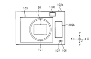
- FIG. 1 is a front view illustrating a schematic configuration of a digital camera 100 which is an embodiment of an imaging device of the present invention.
- FIG. 2 is a rear view illustrating a schematic configuration of the digital camera 100 illustrated in FIG. 1.
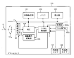
- FIG. 2 is a block diagram illustrating a hardware configuration of the digital camera 100 illustrated in FIG. 1.
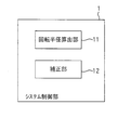
- FIG. 4 is a functional block diagram of a system control unit 1 shown in FIG.
- FIG. 7 is a schematic diagram for explaining a method of calculating a shift blur amount of a captured image signal caused by the digital camera 100 performing yaw rotation about a first axis YJ.
- FIG. 1 is a front view illustrating a schematic configuration of a digital camera 100 which is an embodiment of an imaging device of the present invention.
- FIG. 2 is a rear view illustrating a schematic configuration of the digital camera 100 illustrated in FIG. 1.
- FIG. 2 is a block diagram illustrating a hardware configuration of the digital camera 100 illustrated in FIG. 1.
- FIG. 4 is a
- FIG. 9 is a schematic diagram for explaining a method of calculating a shift blur amount of a captured image signal generated when the digital camera 100 rotates around a second axis XJ.
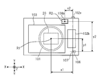
- FIG. 2 is a diagram illustrating a setting example of a rotation axis in the digital camera 100 illustrated in FIG. 1.
- 2 is a flowchart for explaining an operation of the digital camera 100 shown in FIG. 1 in a still image capturing mode.
- 9 is a flowchart for explaining a modification of the operation of the digital camera 100 shown in FIG.
- FIG. 3 is a block diagram illustrating a hardware configuration of a smartphone 200 that is an embodiment of the imaging device of the present invention.
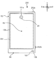
- FIG. 11 is a front view illustrating a schematic configuration of the smartphone 200 illustrated in FIG. 10.
- FIG. 10 is a schematic diagram for explaining a method of calculating a shift blur amount of a captured image signal generated when the digital camera 100 rotates around a second axis XJ.
- FIG. 2 is a diagram illustrating
- FIG. 11 is a functional block diagram of a system control unit 1A shown in FIG. 11 is a flowchart for explaining an operation of the smartphone 200 shown in FIG. 10 in a still image capturing mode.
- 11 is a flowchart for explaining an operation of the smartphone 200 shown in FIG. 10 in a still image capturing mode.
- FIG. 11 is a diagram illustrating a hardware configuration of a smartphone 200A that is a modification example of the smartphone 200 illustrated in FIG. 16 is a flowchart illustrating an operation of the smartphone 200A illustrated in FIG. 15 in a still image capturing mode.
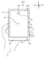
- FIG. 16 is a diagram illustrating a state in which the smartphone 200A illustrated in FIG. 15 is gripped by vertical shooting.
- FIG. 1 is a front view showing a schematic configuration of a digital camera 100 which is an embodiment of the imaging apparatus of the present invention.
- FIG. 2 is a rear view showing a schematic configuration of the digital camera 100 shown in FIG.
- FIG. 3 is a block diagram showing a hardware configuration of the digital camera 100 shown in FIG.
- the digital camera 100 includes a lens barrel 101 and a finder window 108a (see FIG. 1) provided on the front of the housing, a shutter button 102a (see FIGS. 1 and 2) provided on a side surface of the housing, and a housing.
- An image sensor driving unit 105, angular velocity sensor 106, acceleration sensor 107, image processing unit 108, memory 109, and system control unit 1 are provided.
- the lens barrel 101 has an imaging optical system 101a inside.
- the imaging optical system 101a includes at least an imaging lens such as a focus lens or a zoom lens.
- the imaging optical system 101a includes an aperture mechanism or a mechanical shutter mechanism as needed.
- the lens barrel 101 may be fixed to the digital camera 100 main body, or may be detachable from the digital camera 100 main body.
- the imaging device 20 captures an image of a subject through the imaging optical system 101a, and includes a CCD (Charge Coupled Device) image sensor or a CMOS (Complementary Metal Oxide Semiconductor) image sensor. As shown in FIGS. 1 and 2, the light receiving surface of the image sensor 20 is rectangular.
- the shutter button 102a is an operation member for instructing the imaging device 20 to start capturing an image of a subject.
- an imaging instruction signal is input to the system control unit 1.
- the system control unit 1 performs control to cause the imaging device 20 to image the subject.
- the operation unit 102b is a jog dial, a cross key, or a jog dial for performing various operations such as switching between a still image imaging mode for performing still image imaging and a moving image imaging mode for performing moving image imaging, setting of imaging conditions, or selection of an imaging menu. It is composed of buttons and the like.
- various instruction signals are input to the system control unit 1.
- the finder window 108a and the eyepiece window 108b constitute a part of the optical finder.
- the finder window 108a When the user looks through the eyepiece window 108b, the subject can be observed through the finder window 108a.
- an electronic viewfinder may be used instead of the optical viewfinder.
- the finder window 108a is deleted, and the image on the display unit for observing the subject installed inside the housing of the digital camera 100 can be visually recognized by looking through the eyepiece window 108b.
- the digital camera 100 may include a hybrid finder having both functions of an optical finder and an electronic view finder. Regardless of the finder, an eyepiece window 108b for a user to observe a subject is provided on the back of the housing of the digital camera 100.
- the display unit 103 is configured by an LCD (liquid crystal display), an organic EL (Electro Luminescence) display, or the like.
- the display unit 103 displays a live view image.
- the subject can be observed not only by the finder described above but also by the display unit 103.
- the image blur correction mechanism 3 moves the light receiving surface of the image pickup device 20 to a plane perpendicular to the optical axis K of the image pickup optical system 101a, so that the image pickup device 20 picks up an image of a subject and outputs an image output from the image pickup device 20. Corrects image signal blur.
- a state where the light receiving surface of the image sensor 20 is perpendicular to the vertical direction (a state where the optical axis K is parallel to the vertical direction) and a state where the center of the light receiving surface is located on the optical axis K is referred to as a reference state.
- the longitudinal direction of the light receiving surface of the image sensor 20 is defined as a direction X
- the lateral direction of the light receiving surface of the image sensor 20 is defined as a direction Y
- the direction in which the optical axis of the optical system 101a extends is defined as a direction Z (see FIGS. 1 and 2).
- the image blur correction mechanism 3 corrects at least shift blur among image blurs by moving the image sensor 20 in the directions X and Y, respectively.
- the shift blur occurs when the apparatus rotates around two rotation axes (an axis extending in the direction X and an axis extending in the direction Y) perpendicular to the optical axis K of the imaging optical system 101a and orthogonal to each other (referred to as pitch rotation and yaw rotation).
- the acceleration sensor 107 detects at least the acceleration in each of the directions X and Y, which are two directions orthogonal to the optical axis K of the imaging optical system 101a and orthogonal to each other.
- the direction X is one of the two directions.
- the direction Y is the other of the two directions.
- a three-axis acceleration sensor that detects each acceleration in the direction X, the direction Y, and the direction Z is used.
- the acceleration in the direction X detected by the acceleration sensor 107 is referred to as a first acceleration Atx, and the acceleration in the direction Y detected by the acceleration sensor 107 is referred to as a second acceleration Aty.
- the acceleration detected by the acceleration sensor 107 is input to the system control unit 1.
- the angular velocity sensor 106 includes, as shown in FIG. 1, a first angular velocity ⁇ x about a first axis YJ parallel to the direction Y, a second angular velocity ⁇ y about a second axis XJ parallel to the direction X, At least.
- the angular velocity detected by the angular velocity sensor 106 is input to the system control unit 1.
- the angular velocity sensor 106 for example, a three-axis angular velocity sensor that detects an angular velocity around an axis parallel to the direction X, an angular velocity around an axis parallel to the direction Y, and an angular velocity around an axis parallel to the direction Z is used.
- the AFE 104 illustrated in FIG. 3 includes a signal processing circuit that performs correlated double sampling processing, digital conversion processing, and the like on a captured image signal output from the image sensor 20.
- the image processing unit 108 shown in FIG. 3 performs digital signal processing on the captured image signal processed by the AFE 104 to generate captured image data in a JPEG (Joint Photographic Experts Group) format or the like.
- JPEG Joint Photographic Experts Group
- the system control unit 1 shown in FIG. 3 controls the image sensor driving unit 105 and the AFE 104 to cause the image sensor 20 to image a subject, and to output a captured image signal corresponding to the subject image from the image sensor 20. Further, the system control unit 1 controls the image blur correction mechanism 3 based on the motion information of the digital camera 100 detected by the acceleration sensor 107 and the angular velocity sensor 106. The system control unit 1 corrects a shift blur of a captured image signal output from the image sensor 20 by moving the light receiving surface of the image sensor 20 in at least one of the directions X and Y.
- the system controller 1, the acceleration sensor 107, and the angular velocity sensor 106 constitute an image blur correction device.
- the system control unit 1 controls the entire digital camera 100 and includes various processors that execute a program including an image blur correction program to perform processing.
- a programmable logic (CPU) Central Processing Unit
- CPU Central Processing Unit
- FPGA Field Programmable Gate Array
- a dedicated electric circuit or the like which is a processor having a circuit configuration designed to execute a specific process such as a device (Programmable Logic Device: PLD) or an ASIC (Application Specific Integrated Circuit), is included.
- the structure of these various processors is, more specifically, an electric circuit in which circuit elements such as semiconductor elements are combined.
- the system control unit 1 may be configured with one of various processors, or configured with a combination of two or more processors of the same type or different types (for example, a combination of a plurality of FPGAs or a combination of a CPU and an FPGA). May be done.
- the memory 109 includes a RAM (Random Access Memory) and a ROM (Read Only Memory).
- the ROM stores programs (including an image blur correction program) necessary for the operation of the system control unit 1 and various data.
- FIG. 4 is a functional block diagram of the system control unit 1 shown in FIG.
- the system control unit 1 functions as the rotation radius calculation unit 11 and the correction unit 12 by executing a program including the image blur correction program stored in the ROM of the memory 109.
- the turning radius calculation unit 11 calculates a first turning radius Lx when the digital camera 100 rotates (yaw rotates) around the first axis YJ based on the first acceleration Atx and the first angular velocity ⁇ x. Based on the second acceleration Aty and the second angular velocity ⁇ y, a second rotation radius Ly when the digital camera 100 rotates (pitch rotation) around the second axis XJ is calculated.
- FIG. 5 is a schematic diagram for explaining a method of calculating a shift blur amount of a captured image signal caused by rotating the digital camera 100 around the first axis YJ.
- FIG. 5 shows a state where the digital camera 100 is viewed from the direction Y.
- the first rotation when the digital camera 100 yaw-rotates can be calculated by the following equation (A).
- Vx is a speed obtained by integrating the first acceleration Atx in the direction X caused by the yaw rotation.
- the first rotation radius Lx is defined by the distance in the direction Z between the rotation center RS when the digital camera 100 performs yaw rotation and the principal point position P of the imaging optical system 101a of the digital camera 100.
- This Sx is the shift blur amount (first blur amount) of the captured image signal generated in the direction X by the yaw rotation.
- the shift blur amount Sx can be calculated by the following equation (B).
- the rotation angle ⁇ x shown in FIG. 5 can be obtained by integrating the first angular velocity ⁇ x detected by the angular velocity sensor 106.
- FIG. 6 is a schematic diagram for explaining a method of calculating a shift blur amount of a captured image signal caused by the rotation of the digital camera 100 around the second axis XJ.
- FIG. 6 shows a state where the digital camera 100 is viewed from the direction X.
- the second rotation when the digital camera 100 is pitch-rotated The radius Ly can be calculated by the following equation (C).
- Vy is a speed obtained by integrating the second acceleration Aty in the direction Y generated by the pitch rotation.
- the second radius of rotation Ly is defined by the distance in the direction Z between the center of rotation RS when the digital camera 100 performs pitch rotation and the principal point position P of the imaging optical system 101a of the digital camera 100.
- This Sy is a captured image signal shift blur amount (second blur amount) generated in the direction Y by the pitch rotation.
- the shift blur amount Sy can be calculated by the following equation (D).
- the rotation angle ⁇ y shown in FIG. 6 can be obtained by integrating the second angular velocity ⁇ y detected by the angular velocity sensor 106.
- the shift blur amount Sx caused by the yaw rotation of the digital camera 100 can be calculated based on the first angular velocity ⁇ x and the first rotation radius Lx, and the first rotation radius Lx is , Can be calculated based on the first acceleration Atx.
- the shift blur amount Sy caused by the pitch rotation of the digital camera 100 can be calculated based on the second angular velocity ⁇ y and the second rotation radius Ly, and the second rotation radius Ly is It is possible to calculate based on the second acceleration Aty.
- the acceleration sensor 107 detects the digital camera 100 in addition to the acceleration caused by the yaw rotation or the pitch rotation.
- the acceleration (rotational acceleration component) resulting from the rotation of the roll 100 is detected as an error. Due to the influence of this error, there is a possibility that a difference occurs in the accuracy between the first turning radius Lx and the second turning radius Ly obtained from the acceleration.
- the relationship between the rotational acceleration component included in the first acceleration Atx and the rotational acceleration component included in the second acceleration Aty is based on the acceleration sensor 107, the rotation center (rotation axis) when the digital camera 100 rolls, and The rotation axis may vary depending on the use state of the digital camera 100.
- a rotation axis R1 and a rotation axis R2 are preset as rotation axes when the digital camera 100 rolls.
- the rotation axis R1 is an axis extending in the direction Z set at the same position as the optical axis K of the imaging optical system 101a.
- the rotation axis R2 is an axis extending in the direction Z set at the position of the eyepiece window 108b.
- the position of the rotation axis R2 is set at the center of the eyepiece window 108b in the example of FIG. 7, but this position may be anywhere within a range overlapping the eyepiece window 108b.
- the rotation axis R1 is set at the same position as the optical axis K of the imaging optical system 101a.
- the rotation axis R2 is set at the position of the eyepiece window 108b.
- the distance x1 in the direction X between the rotation axis R1 and the acceleration sensor 107 is larger than the distance y1 in the direction Y between the rotation axis R1 and the acceleration sensor 107.
- the error component of the acceleration generated in the direction X due to the roll rotation about the rotation axis R1 is smaller than the error component of the acceleration generated in the direction Y. That is, in this case, the first rotation radius Lx becomes closer to a more accurate value than the second rotation radius Ly.
- the digital camera 100 rolls around the rotation axis R2.
- the distance x2 in the direction X between the rotation axis R2 and the acceleration sensor 107 is smaller than the distance y2 in the direction Y between the rotation axis R2 and the acceleration sensor 107.
- the error component of the acceleration generated in the direction X due to the roll rotation about the rotation axis R2 is larger than the error component of the acceleration generated in the direction Y. That is, in this case, the second turning radius Ly is closer to a more accurate value than the first turning radius Lx.
- the acceleration error due to the roll rotation is used.
- the shift shake amounts Sx and Sy can be accurately calculated.
- the correction unit 12 illustrated in FIG. 4 calculates the shift blur amount Sx based on the first angular velocity ⁇ x and at least one of the first rotation radius Lx and the second rotation radius Ly. Then, the shift blur amount Sy is calculated based on the second angular velocity ⁇ y and at least one of the first rotation radius Lx and the second rotation radius Ly.
- the correction unit 12 selects one of the rotation axes R1 and R2 shown in FIG. 7 based on the usage state of the digital camera 100, and selects one from the selected rotation axis R1 or rotation axis R2 to the acceleration sensor 107. Is determined on the basis of the first distance px in the direction X and the second distance py in the direction Y.
- the correction unit 12 corrects the shift blur in the directions X and Y of the captured image signal by controlling the image blur correction mechanism 3 so as to cancel the shift blur amounts Sx and Sy calculated in this way.
- the use state indicates how the digital camera 100 is used when an imaging instruction for instructing the start of imaging of a subject is issued in a state where the digital camera 100 is set to the imaging mode.
- the use state includes a use state in which the subject is observed using the eyepiece window 108b, and a use state in which the subject is observed without the eyepiece window 108b. .
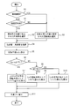
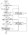
- FIG. 8 is a flowchart for explaining the operation of the digital camera 100 shown in FIG. 1 in the still image capturing mode.
- the shutter button 102a is pressed in a state where the still image capturing mode is set, the operation illustrated in FIG. 8 is started.
- the correction unit 12 of the system control unit 1 determines whether or not the subject is observed using the eyepiece window 108b (step S1).
- a contact sensor is provided in the eyepiece window 108b. Then, when the contact of the object is detected by the contact sensor, the correction unit 12 determines that the observation of the subject is being performed using the eyepiece window 108b. On the other hand, when the contact of the object is not detected by the contact sensor, the correction unit 12 determines that the observation of the subject is being performed without using the eyepiece window 108b.
- a switch for turning on / off the function of the electronic viewfinder is provided in the operation unit 102b instead of the contact sensor. It may be included.
- the correction unit 12 determines that the observation of the subject is performed using the eyepiece window 108b, and the switch of the electronic viewfinder is determined by this switch.
- the function is turned off, it may be determined that the observation of the subject is performed without using the eyepiece window 108b.
- step S2 When determining that the observation of the subject is performed using the eyepiece window 108b (step S1: YES), the correction unit 12 sets the rotation axis R2 shown in FIG. 7 set at the position of the eyepiece window 108b. Select (Step S2).
- step S3 When the correction unit 12 determines that the observation of the subject is being performed without using the eyepiece window 108b (step S1: NO), the rotation axis illustrated in FIG. R1 is selected (step S3).
- step S4 the system control unit 1 acquires the first acceleration Atx and the second acceleration Aty from the acceleration sensor 107, and acquires the first angular velocity ⁇ x and the second angular velocity ⁇ y from the angular velocity sensor 106. (Step S4).
- the turning radius calculation unit 11 of the system control unit 1 calculates the first turning radius Lx by the calculation of Expression (A) based on the first acceleration Atx and the first angular velocity ⁇ x acquired in step S4.
- the second radius of gyration Ly is calculated by the calculation of the equation (C) based on the calculated second acceleration Aty and the second angular velocity ⁇ y acquired in step S4 (step S5).
- the correction unit 12 calculates a difference between the first distance px in the direction X and the second distance py in the direction Y between the rotation axis selected in step S2 or step S3 and the acceleration sensor 107, It is determined whether this difference is less than a predetermined threshold TH (step S6).
- the information of the first distance px and the second distance py in the directions X and Y between the rotation axes R1 and R2 and the acceleration sensor 107 is stored in the ROM of the memory 109 in advance.
- step S6 When determining that the difference is less than the threshold value TH (step S6: YES), the correction unit 12 determines both the first rotation radius Lx and the second rotation radius Ly calculated in step S5.
- the shift blur amounts Sx and Sy are calculated using the above.
- the correction unit 12 substitutes the average value of the first turning radius Lx and the second turning radius Ly calculated in step S5 into “Lx” in the above equation (B) to shift the shift blur. Calculate the quantity Sx. Similarly, the correction unit 12 substitutes the average value of the first turning radius Lx and the second turning radius Ly calculated in step S5 into “Ly” of the above equation (D), and shift shift amount Sy Is calculated (step S7).
- step S6 When determining that the difference is equal to or greater than the threshold TH (step S6: NO), the correction unit 12 determines whether the first distance px is greater than the second distance py (step S8). ).
- step S8 YES
- the correction unit 12 uses only the first rotation radius Lx calculated in step S5 to shift shift amounts Sx, Sx, Sy is calculated.
- the correction unit 12 calculates the shift blur amount Sx by substituting the first rotation radius Lx calculated in step S5 into “Lx” in the above equation (B), and
- the shift blur amount Sy is calculated by substituting the first rotation radius Lx calculated in step S5 into "Ly” of D) (step S9).
- step S8 NO
- the correction unit 12 uses only the second rotation radius Ly calculated in step S5 to shift the shift blur Sx, Sy is calculated.
- the correction unit 12 calculates the shift blur amount Sx by substituting the second rotation radius Ly calculated in step S5 into “Lx” in the above equation (B), and
- the shift blur amount Sy is calculated by substituting the second rotation radius Ly calculated in step S5 into "Ly” of D) (step S10).
- the correcting unit 12 controls the image blur correcting mechanism 3 so as to cancel the shift blurring amounts Sx and Sy, and outputs from the image sensor 20.
- the shift blur of the captured image signal is corrected (step S11).
- the digital camera 100 selects the rotation axis assumed to be the rotation center when the digital camera 100 performs the roll rotation, and determines the first rotation radius based on the distance between the rotation axis and the acceleration sensor 107. Whether the shift blur amounts Sx and Sy are calculated using only Lx or the shift blur amounts Sx and Sy are calculated using only the second turning radius Ly, or both the first turning radius Lx and the second turning radius Ly Is used to determine whether to calculate the shift blur amounts Sx and Sy.
- the difference between the first distance px and the second distance py between the selected rotation axis and the acceleration sensor 107 is less than the threshold value TH, the accuracy of the first rotation radius Lx and the second rotation radius Ly is reduced. It can be determined that there is no difference. For this reason, in this case, by calculating the shift blur amounts Sx and Sy using both the first rotation radius Lx and the second rotation radius Ly, it is assumed that roll rotation occurs during pitch rotation or yaw rotation. Also, the calculation accuracy of the shift blur amounts Sx and Sy can be improved.
- the difference between the first distance px and the second distance py between the selected rotation axis and the acceleration sensor 107 is equal to or larger than the threshold value TH, and the first distance px is larger than the second distance py.
- the first rotation radius Lx is closer to an accurate value than the second rotation radius Ly. Therefore, in this case, by calculating the shift blur amounts Sx and Sy using only the first rotation radius Lx, even if the roll rotation occurs during the pitch rotation or the yaw rotation, the shift blur amounts Sx and Sy are calculated. Calculation accuracy can be improved.
- the difference between the first distance px and the second distance py between the selected rotation axis and the acceleration sensor 107 is equal to or larger than the threshold value TH, and the first distance px is smaller than the second distance py.
- the second rotation radius Ly is closer to an accurate value than the first rotation radius Lx.
- the shift blur amounts Sx and Sy are calculated using only the second rotation radius Ly, so that even if roll rotation occurs during pitch rotation or yaw rotation, the shift blur amounts Sx and Sy are calculated. Calculation accuracy can be improved.
- step S7 the correction unit 12 calculates the shift blur amount Sx by substituting the second rotation radius Ly calculated in step S5 into “Lx” in the above equation (B),
- the shift blur amount Sy may be calculated by substituting the first rotation radius Lx calculated in step S5 for “Ly” in (D). By doing so, it is possible to absorb the difference between the turning radii caused by the slight difference between the first distance px and the second distance py, and to improve the calculation accuracy of the shift blur amounts Sx and Sy.
- FIG. 9 is a flowchart for explaining a modification of the operation of the digital camera 100 shown in FIG.
- the flowchart shown in FIG. 9 shows an operation after the shutter button 102a is pressed in a state where the still image capturing mode or the moving image capturing mode is set.
- FIG. 9 The flowchart shown in FIG. 9 is the same as FIG. 8 except that step S0 is added.
- step S0 is added.
- FIG. 9 the same processes as those in FIG. 8 are denoted by the same reference numerals, and description thereof will be omitted.
- step S0 the correction unit 12 of the system control unit 1 determines whether the imaging mode is the moving image imaging mode.
- the correction unit 12 shifts the processing to step S3, and when the imaging mode is the still image imaging mode (step S0: NO). Shifts the processing to step S1.
- the rotation axis R1 is selected in the moving image capturing mode regardless of the use state of the digital camera 100.
- the influence on the acceleration in the directions X and Y due to the roll rotation that can be caused by the pressing of the shutter button 102a of the digital camera 100 becomes large in the still image capturing mode in which the exposure is performed only once immediately after the pressing of the shutter button 102a. .
- the digital camera 100 is likely to be rolled easily around the rotation axis R1 because the digital camera 100 is often held with both hands for image capturing. For this reason, shift blur correction can be performed with high accuracy by selecting the rotation axis R1 when capturing a moving image.
- FIG. 10 is a block diagram showing a hardware configuration of a smartphone 200 which is an embodiment of the imaging device of the present invention.
- FIG. 11 is a front view showing a schematic configuration of smartphone 200 shown in FIG. 10, the same components as those in FIG. 3 are denoted by the same reference numerals.
- the communication unit 202 is a functional unit for performing short-range wireless communication or data communication via a mobile phone network.
- a display unit 103 is formed on the front of the housing of the smartphone 200, and the display unit 103 is integrally formed with a touch panel 201.
- An imaging optical system 101a is formed on the rear surface of the housing of the smartphone 200 (the surface opposite to the front surface on which the display unit 103 is formed).
- a state in which the light receiving surface of the imaging element 20 is perpendicular to the vertical direction (a state in which the optical axis K is parallel to the vertical direction) and a state in which the center of the light receiving surface is located on the optical axis K is referred to as a reference state.
- the longitudinal direction of the light receiving surface of the image sensor 20 is defined as a direction X
- the lateral direction of the light receiving surface of the image sensor 20 is defined as a direction Y
- a direction orthogonal to the direction X and the direction Y ( The direction in which the optical axis of the imaging optical system 101a extends) is defined as a direction Z.
- the planar shape of the display unit 103 viewed from the direction Z is a rectangle.
- the longitudinal direction of the display unit 103 is the direction Y, and the short direction of the display unit 103 is the direction X.
- a button 202a is formed at the upper end in the direction Y of the housing of the smartphone 200.
- a button 202b is formed at the right end of the housing of the smartphone 200 in the direction X.
- the button 202a and the button 202b each function as a shutter button for instructing the start of imaging of a subject when the camera application of the smartphone 200 is activated and the smartphone 200 shifts to the imaging mode.
- the button 202a and the button 202b each constitute an operation member provided at a different position from the display unit 103.
- the rotation axis R3, the rotation axis R4, and the rotation axis R5 are the rotation axes when the smartphone 200 rotates around the rotation axis parallel to the optical axis K (roll rotation). It is set in advance.
- the rotation axis R5 is an axis extending in the direction Z set at the center of the display unit 103.
- the rotation axis R3 is an axis extending in the direction Z set near the upper end in the direction Y among the left ends in the direction X of the housing of the smartphone 200.
- the rotation axis R4 is an axis extending in the direction Z set near the left end in the direction X of the lower end in the direction Y of the housing of the smartphone 200.
- Rotation axis R3 and rotation axis R4 constitute two rotation axes at positions different from optical axis K.
- the rotation axis R3 is one of the two rotation axes
- the rotation axis R4 is the other of the two rotation axes.
- the smartphone 200 does not have an eyepiece window unlike the digital camera 100 of FIG. Therefore, when the smartphone 200 shifts to the imaging mode, a live view image obtained by imaging with the imaging device 20 is displayed on the display unit 103.
- the posture of the smartphone 200 is determined such that the longitudinal direction (that is, the direction Y) of the display unit 103 and the vertical direction are substantially parallel.
- the posture of the smartphone 200 is determined such that the short direction (that is, the direction X) of the display unit 103 and the vertical direction are substantially parallel.
- the user holds the vicinity of the button 202a with the right finger and the rotation axis R4. Compose the shot while supporting the area with your left finger. Then, the user images the subject by pressing the button 202a in the direction Y. In this way, assuming a case in which vertical shooting is performed using the button 202a, there is a high possibility that the smartphone 200 rolls around the vicinity of the left finger supporting the smartphone 200.
- the rotation axis R4 is set at a position substantially diagonal to the button 202a assuming such a case.
- the user holds the vicinity of the button 202b with the right finger and rotates the rotation axis.
- the composition is determined while supporting the vicinity of R3 with the left finger.
- the user images the subject by pressing the button 202b in the direction X.
- the rotation axis R3 is set at a position substantially diagonal to the button 202b assuming such a case.
- the imaging instruction can be issued to the system control unit 1A by operating the touch panel 201 without using the buttons 202a and 202b.
- the housing of the smartphone 200 is often firmly held with both hands. Therefore, in this case, there is a high possibility that the smartphone 200 rolls around the center of the display unit 103.
- the rotation axis R5 is set at the center of the display unit 103 assuming such a case.
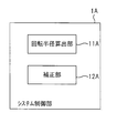
- FIG. 12 is a functional block diagram of the system control unit 1A shown in FIG.
- the system control unit 1A functions as a rotation radius calculation unit 11A and a correction unit 12A by executing a program including an image blur correction program stored in the ROM of the memory 109.
- the system control unit 1A, the acceleration sensor 107, and the angular velocity sensor 106 constitute an image blur correction device.
- the function of the turning radius calculation unit 11A is the same as that of the turning radius calculation unit 11 in FIG.
- the function of the correction unit 12A is substantially the same as that of the correction unit 12 in FIG. 4 except that the rotation axis to be selected is any of the rotation axes R3, R4, and R5 shown in FIG. Is different from the correction unit 12.
- the correction unit 12A selects the rotation axis R5 in a use state in which imaging is performed by operating the touch panel 201 (so-called touch imaging), and performs imaging in the direction Y by operating the button 202a.
- a vertical use state so-called vertical shooting state
- the rotation axis R4 is selected, an image is taken by operating the button 202b, and the direction X is a vertical direction (so-called horizontal shooting state).
- the rotation axis R3 is selected.
- the usage state of the smartphone 200 indicates how the smartphone 200 is being used when the imaging mode is set.
- the use state includes a state in which touch imaging is performed, a state in which a button operation is performed in vertical shooting, and a state in which a button operation is performed in horizontal shooting.
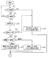
- FIGS. 13 and 14 are flowcharts for explaining the operation of the smartphone 200 shown in FIG. 10 in the still image capturing mode.
- the correction unit 12A of the system control unit 1A selects the rotation axis R5 set at the center of the display unit 103 when the imaging instruction is given by operating the touch panel 201 (step S21: YES) (step S22). .
- the correction unit 12A determines whether the imaging instruction has been given by either the button 202a or the button 202b (step S23). ).
- the correction unit 12A returns the process to step S21 when the imaging instruction has not been issued by one of the button 202a and the button 202b (step S23: NO).
- the correction unit 12 ⁇ / b> A changes the orientation of the smartphone 200 to the direction X based on the detection signal of the acceleration sensor 107 when the imaging instruction is performed by one of the button 202 a and the button 202 b (step S ⁇ b> 23: YES). It is determined whether the shooting direction is a horizontal shooting attitude in which the vertical direction is set or the vertical shooting attitude in which the direction Y is the vertical direction (step S24).
- step S24 If the result of determination in step S24 is that it is not possible to determine the vertical shooting posture and the horizontal shooting posture (step S25: YES), the correction unit 12A selects the rotation axis R5 in step S22.
- step S24 when it can be determined that the camera is in the vertical shooting posture (step S26: vertical shooting), the correction unit 12A selects the rotation axis R4 set at a position assuming a vertical shooting case. (Step S27).
- step S24 when it can be determined that the camera is in the horizontal shooting posture (step S26: horizontal shooting), the correction unit 12A selects the rotation axis R3 set at a position assuming a horizontal shooting case. (Step S28).
- the system control unit 1A acquires the first acceleration Atx and the second acceleration Aty from the acceleration sensor 107, and obtains the angular velocity
- the first angular velocity ⁇ x and the second angular velocity ⁇ y are obtained from the sensor 106 (Step S29).
- the turning radius calculation unit 11A calculates the first turning radius Lx by the calculation of Expression (A) based on the first acceleration Atx and the first angular velocity ⁇ x acquired in step S29, and then proceeds to step S29.
- the second rotation radius Ly is calculated by the calculation of Expression (C) based on the second acceleration Aty and the second angular velocity ⁇ y acquired in (Step S30).
- the correction unit 12A determines the first distance px in the direction X and the second distance in the direction Y between the rotation axis selected in any of steps S22, S27, and S28 and the acceleration sensor 107. py is calculated, and it is determined whether or not the difference is less than the threshold value TH (step S31).
- the information of the first distance px and the second distance py in the directions X and Y between the rotation axes R3, R4 and R5 and the acceleration sensor 107 is stored in the ROM of the memory 109 of the smartphone 200 in advance.
- step S31 When determining that the difference is less than the threshold value TH (step S31: YES), the correction unit 12A determines both the first rotation radius Lx and the second rotation radius Ly calculated in step S30. Then, the shift blur amounts Sx and Sy are calculated (step S32).
- the calculation method here is the same as step S7 in FIG.
- step S31 When determining that the difference is equal to or greater than the threshold TH (step S31: NO), the correction unit 12A determines whether the first distance px is greater than the second distance py (step S33). ).
- step S33 YES
- the correction unit 12A calculates the first distance calculated in step S30 by the same method as step S9 in FIG.
- the shift shake amounts Sx and Sy are calculated using only the turning radius Lx (step S34).
- step S33: NO the correction unit 12A calculates the second distance calculated in step S30 by the same method as step S10 in FIG.
- the shift shake amounts Sx and Sy are calculated using only the turning radius Ly.
- the correction unit 12A controls the image blur correction mechanism 3 so as to cancel the shift blur amounts Sx and Sy, and outputs from the image sensor 20.
- the shift blur of the captured image signal is corrected (step S36).
- the smartphone 200 when an image is captured by operating the touch panel 201, it is determined that the roll can be rotated around the rotation axis R5, and the rotation radius used for calculating the shift blur amounts Sx and Sy is selected.
- the vertical shooting is performed by the operation of the button 202a, it is determined that the roll can be rotated around the rotation axis R4, and the rotation radius used for calculating the shift blur amounts Sx and Sy is selected.
- the image is taken in the horizontal direction, it is determined that the roll can be rotated around the rotation axis R3, and the radius of rotation used for calculating the shift blur amounts Sx and Sy is selected. Therefore, the shift blur amount can be calculated using a turning radius closer to a more accurate value in accordance with the use state of the smartphone 200, and the shift blur of the captured image signal can be corrected with high accuracy.
- the rotation axis R5 set at the center of the display unit 103 is selected. You.
- the distance between the rotation axis R3 and the acceleration sensor 107 is the correct distance (the rotation axis R4 (Distance from the acceleration sensor 107).
- the rotation axis R5 when the rotation axis R5 is selected, the distance between the rotation axis R5 and the acceleration sensor 107 approaches the correct distance. For this reason, even in a situation where the posture cannot be determined, it is possible to prevent the calculation accuracy of the shift blur amounts Sx and Sy from being reduced, and to correct the shift blur of the captured image signal with high accuracy.
- step S21 is not essential and may be a deleted operation.
- the rotation axis set in the smartphone 200 may be only the rotation axis R3 and the rotation axis R4.
- the operation of the smartphone 200 in the still image capturing mode in this case is such that when Steps S21 and S22 are deleted in FIGS. 13 and 14 and the determination in Step S25 is YES, for example, the shift blur amounts Sx and Sy Is calculated, and only translation blur correction is performed.
- step S21 is deleted in FIGS. 13 and 14, and the process of step S22 is changed to a process of selecting the rotation axis R1.
- FIG. 15 is a diagram showing a hardware configuration of a smartphone 200A which is a modification of the smartphone 200 shown in FIG.
- the smartphone 200A shown in FIG. 15 is the same as the smartphone 200 except that a grip sensor 211 is added.
- the grip sensor 211 is a sensor for detecting that the housing of the smartphone 200A is gripped by a hand, and is configured by, for example, a piezoelectric sensor or the like.
- the appearance of the smartphone 200A is the same as the smartphone 200.
- FIG. 16 is a flowchart for explaining the operation of smartphone 200A shown in FIG. 15 in the still image capturing mode.
- the flowchart shown in FIG. 16 is the same as the flowchart shown in FIG. 13 except that step S40 is added between steps S26 and S27.
- the processing after step S27 shown in FIG. 16 is the same as that in FIG.
- step S26 vertical shooting
- the correction unit 12A of the system control unit 1A of the smartphone 200A determines the smartphone 200A based on the output signal of the grip sensor 211. It is determined whether or not is held (step S40).
- step S40 determines that the smartphone 200A is being held (step S40: YES)
- the correcting unit 12A selects the rotation axis R5 set at the center of the display unit 103 in step S22.
- step S40 determines that the smartphone 200A is not gripped (step S40: NO)
- the correcting unit 12A selects the rotation axis R4 in step S27.
- the posture of the smartphone 200A is a vertical shooting posture in which the direction Y is a vertical direction, as shown in FIG. 17, the user holds the smartphone 200A with the left hand H and fixes it, and then presses the button with the right finger in that state.
- an image is taken by pressing the button 202a.
- the possibility that the smartphone 200A rolls around the rotation axis R4 is reduced, so that the shift blur correction can be performed by selecting the rotation axis R5. It is possible to further improve the accuracy of.
- the smartphone 200 or the smartphone 200A is in the moving image capturing mode, whether or not it is touch imaging, whether or not it is button imaging, regardless of whether it is portrait shooting or landscape shooting, when an imaging instruction is given, It is preferable that the correction unit 12A calculates the shift shake amounts Sx and Sy by selecting the rotation axis R5.
- the smartphones 200 and 200A are often held with both hands to perform the image capturing. Therefore, it is considered that the smartphones 200 and 200A easily roll around the rotation axis R5. For this reason, the shift blur correction can be performed with high accuracy by selecting the rotation axis R5 when capturing a moving image.
- the shift blur is corrected by moving the image sensor 20 by the image blur correction mechanism 3, but the invention is not limited thereto.
- the image blur correction mechanism 3 may be a mechanism that corrects shift blur by moving a correction lens included in the imaging optical system 101a, or a correction lens included in the imaging element 20 and the imaging optical system 101a.
- the shift blur may be corrected by moving both of the lenses. Further, a configuration may be employed in which electronic image blur correction is performed without optically performing image blur correction as in the image blur correction mechanism 3.
- An image blur correction device that corrects a blur of a captured image signal output from an imaging element that captures an object through an imaging optical system, Detecting a first acceleration in one of two directions orthogonal to an optical axis of the imaging optical system of the imaging apparatus including the imaging element and a second acceleration in the other of the two directions; Acceleration sensor, Detecting a first angular velocity of the imaging device about a first axis parallel to the other direction and a second angular velocity of the imaging device about a second axis parallel to the one direction; An angular velocity sensor, Based on the first acceleration and the first angular velocity, calculate a first radius of rotation about the first axis of the imaging device, based on the second acceleration and the second angular velocity, A turning radius calculation unit that calculates a second turning radius around the second axis of the imaging device, The first blur amount in the one of the directions of the captured image signal caused by the imaging device rotating about the first axis, the first angular velocity, the first rotation radius and A second
- An amount is calculated based on the second angular velocity and at least one of the first rotation radius and the second rotation radius, and a correction unit that corrects the calculated shake amount is provided.
- the correction unit selects one of the plurality of rotation axes based on a use state of the imaging device from a plurality of predetermined rotation axes parallel to the optical axis, and selects the acceleration from the selected rotation axis.
- An image blur correction device for determining the radius of gyration used for calculating the first blur amount and the second blur amount based on a distance to a sensor in the two directions.
- the correction unit includes a first distance in the one direction from the selected rotation axis to the acceleration sensor, and a second distance in the other direction from the selected rotation axis to the acceleration sensor. If the difference with the distance is equal to or greater than a predetermined value, and the first distance is greater than the second distance, the first angular velocity and the first radius of rotation based on the first angular velocity An image blur correction device that calculates a first blur amount and calculates the second blur amount based on the second angular velocity and the first rotation radius.
- the image blur correction device is configured to determine the difference based on the first angular velocity and the second turning radius when the difference is equal to or greater than the value and the first distance is smaller than the second distance.
- An image shake correction apparatus that calculates a first shake amount and calculates the second shake amount based on the second angular velocity and the second rotation radius.
- the image blur correction device when the difference is less than the value, calculates the first shake amount based on the first angular velocity and the second rotation radius, the second angular velocity and the An image blur correction device that calculates the second blur amount based on a first rotation radius.
- the image blur correction device includes an eyepiece window for observing the subject,
- the plurality of rotation axes include a rotation axis set at the position of the eyepiece window, and a rotation axis set at the same position as the optical axis,
- the correction unit selects the rotation axis set at the position of the eyepiece window, and the eyepiece window is not used.
- An image blur correction apparatus that selects the rotation axis set at the same position as the optical axis in the use state in which the observation of the subject is being performed by the apparatus.
- the image blur correction device includes two rotation axes at positions different from the optical axis,
- the correction unit selects one of the two rotation axes in the case of the use state in which the one of the directions is the vertical direction, and selects the one of the two rotation shafts in the use state in which the other direction is the vertical direction.
- the image blur correction device includes a rotation axis at the same position as the optical axis,
- the correction unit is located at the same position as the optical axis in the use state where it is impossible to determine whether the one of the directions is a vertical direction and the other of the directions is a vertical direction.
- the image blur correction device includes a rotation axis at the same position as the optical axis,
- the correction unit selects the rotation axis located at the same position as the optical axis when the imaging device is set to the moving image imaging mode, and when the imaging device is set to the still image imaging mode.
- An image blur correction apparatus that selects the rotation axis based on the use state.
- the imaging device includes a display unit provided on a surface opposite to the imaging optical system, a touch panel formed on the display unit, and an imaging instruction provided at a position different from the display unit.
- An operating member The plurality of rotation axes are different from the two rotation axes and further include a rotation axis set at a center position of the display unit, In the case of the use state in which the imaging is performed by the operation of the touch panel, the correction unit selects the rotation axis set at the center position, and performs the imaging by the operation of the operation member.
- the image blur correction device (10) The image blur correction device according to (10), The correction unit is set to the center position in the case of the use state in which it is impossible to determine whether the one of the directions is a vertical direction and the other of the directions is a vertical direction.
- the image blur correction device according to (10) or (11),
- the imaging device includes a grip sensor that detects that the user is grasped, The longitudinal direction of the display unit coincides with the other direction, the short direction of the display unit coincides with the one of the directions, The use state in which the correction unit is configured so that the other direction is a vertical direction, an image is captured by operating the operation member, and the grip sensor detects that the imaging device is gripped.
- an image blur correction device that selects the rotation axis set at the center position.
- the image blur correction device according to any one of (10) to (12), The correction unit selects the rotation axis set at the center position when the imaging device is set to the moving image imaging mode, and selects the rotation axis when the imaging device is set to the still image imaging mode. Is an image blur correction device that selects the rotation axis based on the use state.
- An image blur correction device according to any one of (1) to (13), An imaging device comprising: the imaging device.
- An image blur correction method for correcting blur of a captured image signal output from an image sensor that captures an object through an imaging optical system Detecting a first acceleration in one of two directions orthogonal to an optical axis of the imaging optical system of the imaging apparatus including the imaging element and a second acceleration in the other of the two directions; Acceleration sensor, and a first angular velocity of the imaging device about a first axis parallel to the other direction and a second angular velocity of the imaging device around a second axis parallel to the one direction.
- an angular velocity sensor that detects a second angular velocity, based on the first acceleration and the first angular velocity, calculates a first rotational radius of the imaging device around the first axis, Based on the second acceleration and the second angular velocity, a turning radius calculation step of calculating a second turning radius around the second axis of the imaging device, The first blur amount in the one of the directions of the captured image signal caused by the imaging device rotating about the first axis, the first angular velocity, the first rotation radius and A second blur in the other direction of the captured image signal, which is calculated by rotating the imaging device around the second axis, based on at least one of the second rotational radii.
- the amount, the second angular velocity, based on at least one of the first radius of gyration and the second radius of gyration, a correction step to correct the calculated blur amount In the correcting step, one rotation axis is selected from a plurality of predetermined rotation axes parallel to the optical axis based on a use state of the imaging apparatus, and the acceleration is selected from the selected rotation axis.
- the imaging device includes an eyepiece window for observing the subject,
- the plurality of rotation axes include a rotation axis set at the position of the eyepiece window, and a rotation axis set at the same position as the optical axis,
- the rotation axis set at the position of the eyepiece window is selected, and the eyepiece window is not used.
- the plurality of rotation axes include two rotation axes at positions different from the optical axis, In the correction step, one of the two rotation shafts is selected in the case of the use state in which the one of the directions is the vertical direction, and in the case of the use state in which the other direction is the vertical direction.
- the image blur correction method according to (21), include a rotation axis at the same position as the optical axis, In the correction step, in the case of the use state in which it is impossible to determine whether the one of the directions is a vertical direction and the other of the directions is a vertical direction, the same position as the optical axis is used.
- the image blur correction method according to any one of (22),
- the plurality of rotation axes include a rotation axis at the same position as the optical axis, In the correcting step, when the imaging device is set to the moving image imaging mode, the rotation axis located at the same position as the optical axis is selected, and when the imaging device is set to the still image imaging mode.
- the imaging device includes a display unit provided on a surface opposite to the imaging optical system, a touch panel formed on the display unit, and an imaging instruction provided at a position different from the display unit.
- An operating member The plurality of rotation axes are different from the two rotation axes and further include a rotation axis set at a center position of the display unit, In the correction step, in the case of the use state in which imaging is performed by operating the touch panel, the rotation axis set at the center position is selected, and imaging is performed by operating the operation member, and In the case of the use state in which the direction is the vertical direction, one of the two rotation axes is selected, an image is taken by operating the operation member, and the other direction is the vertical direction. In the case of (1), an image blur correction method of selecting the other of the two rotation axes.
- the imaging device includes a grip sensor that detects that the user is grasped,
- the longitudinal direction of the display unit coincides with the other direction
- the short direction of the display unit coincides with the one of the directions
- the other of the directions is a vertical direction
- an image is captured by operating the operation member
- the grip sensor detects that the imaging device is gripped.
- An image blur correction program that corrects a blur of a captured image signal output from an image sensor that captures an object through an imaging optical system, Detecting a first acceleration in one of two directions orthogonal to an optical axis of the imaging optical system of the imaging apparatus including the imaging element and a second acceleration in the other of the two directions; Acceleration sensor, and a first angular velocity of the imaging device about a first axis parallel to the other direction and a second angular velocity of the imaging device around a second axis parallel to the one direction.
- an angular velocity sensor that detects a second angular velocity, based on the first acceleration and the first angular velocity, calculates a first rotational radius of the imaging device around the first axis, Based on the second acceleration and the second angular velocity, a turning radius calculation step of calculating a second turning radius around the second axis of the imaging device, The first blur amount in the one of the directions of the captured image signal caused by the imaging device rotating about the first axis, the first angular velocity, the first rotation radius and A second blur in the other direction of the captured image signal, which is calculated by rotating the imaging device around the second axis, based on at least one of the second rotational radii.
- one rotation axis is selected from a plurality of predetermined rotation axes parallel to the optical axis based on a use state of the imaging apparatus, and the acceleration is selected from the selected rotation axis.
- the present invention is highly convenient and effective when applied to a digital camera or a smartphone.
- Image Stabilization Mechanism 20 Image Sensor 100 Digital Camera 101 Lens Barrel 101a Imaging Optical System 102a Shutter Button 102b Operation Unit 103 Display Unit 104 AFE 105 Image sensor driving unit 106 Angular velocity sensor 107 Acceleration sensor 108 Image processing unit 109 Memory 108a Finder window 108b Eyepiece window 1, 1A System control unit 11, 11A Rotation radius calculation unit 12, 12A Correction unit K Optical axis RS Rotation center P Principal point Position YJ First axis XJ Second axis ⁇ x First angular velocity ⁇ y Second angular velocity Lx First rotation radius Ly Second rotation radius Sx, Sy Shift blurring ⁇ x, ⁇ y Rotation angles R1, R2, R3, R4 , R5 Rotation axis 200, 200A Smartphone 201 Touch panel 202 Communication unit 202a, 202b Button 211 Grip sensor H Left hand
Landscapes
- Engineering & Computer Science (AREA)
- Multimedia (AREA)
- Signal Processing (AREA)
- Human Computer Interaction (AREA)
- Physics & Mathematics (AREA)
- General Physics & Mathematics (AREA)
- Adjustment Of Camera Lenses (AREA)
- Studio Devices (AREA)
Abstract
撮像装置のピッチ回転とヨー回転によって生じる撮像画像信号のブレを高精度に補正することのできる像ブレ補正装置、この像ブレ補正装置を備える撮像装置、像ブレ補正方法、及び像ブレ補正プログラムを提供する。 像ブレ補正装置は、加速度センサ(107)と、角速度センサ(106)と、システム制御部(1)とを備える。システム制御部(1)は、回転軸R1,R2からデジタルカメラ(100)の使用状態に基づいて1つを選択し、選択した回転軸から加速度センサ(107)までの距離px,pyと、角速度ωx,ωyと、加速度Atx,Atyとに基づいて、デジタルカメラ(100)が第二の軸XJの回りに回転することにより方向Yに生じるシフトブレ量Sy及び第一の軸YJの回りに回転することにより方向Xに生じるシフトブレ量Sxを算出する。
Description
本発明は、像ブレ補正装置、撮像装置、像ブレ補正方法、及び像ブレ補正プログラムに関する。
撮像光学系を通して被写体を撮像する撮像素子を備えた撮像装置には、装置が振動することによって生じる撮像画像信号のブレ(以下、像ブレともいう)を補正するための像ブレ補正機能を有するものがある。像ブレには、シフトブレと、回転ブレと、がある。
シフトブレは、撮像素子の受光面の直交する2辺のそれぞれに沿った方向における撮像画像信号のブレであり、装置が並進運動することで生じる撮像画像信号のブレ(以下、並進ブレともいう)と、撮像光学系の光軸に垂直且つ互いに直交する2つの回転軸のそれぞれの回りに装置が回転(ピッチ回転及びヨー回転という)することで生じる撮像画像信号のブレ(以下、角度ブレともいう)とを含む。
回転ブレは、撮像光学系の光軸に平行な回転軸の回りに装置が回転(ロール回転ともいう)することで生じる撮像画像信号のブレである。
特許文献1、2には、角度ブレを補正することのできるカメラが記載されている。
ピッチ回転によって生じたシフトブレSyは、撮像装置がピッチ回転する際の回転中心から撮像光学系の主点位置までの距離を回転半径Lyとし、撮像装置のピッチ回転時の回転角度をθyとした場合に、Sy=Ly・tanθyの演算によって求めることができる。
同様に、ヨー回転によって生じたシフトブレSxは、撮像装置がヨー回転する際の回転中心から撮像光学系の主点位置までの距離を回転半径Lxとし、撮像装置のヨー回転時の回転角度をθxとした場合に、Sx=Lx・tanθxの演算によって求めることができる。
回転角度θxと回転角度θyは、撮像装置に角速度センサを設けておき、この角速度センサにより検出される角速度に基づいて求めることができる。
回転半径Lxと回転半径Lyは、撮像装置のヨー回転及びピッチ回転によって生じる加速度と、角速度センサにより検出される角速度とに基づいて求めることができる。
しかし、撮像装置がヨー回転又はピッチ回転しているのと同時にロール回転している場合を想定すると、加速度センサは、撮像装置のヨー回転又はピッチ回転に起因する加速度に加え、撮像装置のロール回転に起因した加速度を検出してしまう。このようにロール回転に起因した加速度が検出されると、この加速度に基づいて算出される回転半径Lxと回転半径Lyに誤差が生じ得ることとなり、シフトブレの補正精度が低下する可能性がある。
撮像装置がロール回転するときの回転中心の位置が予め決まっていれば、回転半径Lxと回転半径Lyのどちらかに誤差が生じないように加速度センサを配置しておくことで、誤差のない回転半径を用いてシフトブレを精度よく補正することは可能である。しかし、実際の利用シーンにおいては、この回転中心の位置が一定ではなく変化することがある。特許文献1及び特許文献2では、こういった回転中心の位置が変化することについて考慮されていない。
本発明は、上記事情に鑑みてなされたものであり、撮像装置のピッチ回転とヨー回転によって生じる撮像画像信号のブレを高精度に補正することのできる像ブレ補正装置、この像ブレ補正装置を備える撮像装置、像ブレ補正方法、及び像ブレ補正プログラムを提供することを目的とする。
本発明の像ブレ補正装置は、撮像光学系を通して被写体を撮像する撮像素子から出力される撮像画像信号のブレを補正する像ブレ補正装置であって、上記撮像素子を含む撮像装置の上記撮像光学系の光軸に直交し且つ互いに直交する2つの方向の一方の方向の第一の加速度及び上記2つの方向の他方の方向の第二の加速度を検出する加速度センサと、上記他方の上記方向に平行な第一の軸の回りの上記撮像装置の第一の角速度及び上記一方の上記方向に平行な第二の軸の回りの上記撮像装置の第二の角速度を検出する角速度センサと、上記第一の加速度と上記第一の角速度に基づいて、上記撮像装置の上記第一の軸回りの第一の回転半径を算出し、上記第二の加速度と上記第二の角速度に基づいて、上記撮像装置の上記第二の軸回りの第二の回転半径を算出する回転半径算出部と、上記撮像装置が上記第一の軸の回りに回転することにより生じる上記撮像画像信号の上記一方の上記方向への第一のブレ量を、上記第一の角速度と、上記第一の回転半径及び上記第二の回転半径の少なくとも一方と、に基づいて算出し、上記撮像装置が上記第二の軸の回りに回転することにより生じる上記撮像画像信号の上記他方の上記方向への第二のブレ量を、上記第二の角速度と、上記第一の回転半径及び上記第二の回転半径の少なくとも一方と、に基づいて算出し、算出したブレ量を補正する補正部と、を備え、上記補正部は、上記光軸に平行な予め決められた複数の回転軸の中から、上記撮像装置の使用状態に基づいて1つの上記回転軸を選択し、上記選択した上記回転軸から上記加速度センサまでの上記2つの方向における距離に基づいて、上記第一のブレ量と上記第二のブレ量の算出に用いる上記回転半径を決定するものである。
本発明の撮像装置は、上記像ブレ補正装置と、上記撮像素子と、を備えるものである。
本発明の像ブレ補正方法は、撮像光学系を通して被写体を撮像する撮像素子から出力される撮像画像信号のブレを補正する像ブレ補正方法であって、上記撮像素子を含む撮像装置の上記撮像光学系の光軸に直交し且つ互いに直交する2つの方向の一方の方向の第一の加速度及び上記2つの方向の他方の方向の第二の加速度を検出する加速度センサ、及び、上記他方の上記方向に平行な第一の軸の回りの上記撮像装置の第一の角速度及び上記一方の上記方向に平行な第二の軸の回りの上記撮像装置の第二の角速度を検出する角速度センサにより検出された、上記第一の加速度と上記第一の角速度に基づいて、上記撮像装置の上記第一の軸回りの第一の回転半径を算出し、上記第二の加速度と上記第二の角速度に基づいて、上記撮像装置の上記第二の軸回りの第二の回転半径を算出する回転半径算出ステップと、上記撮像装置が上記第一の軸の回りに回転することにより生じる上記撮像画像信号の上記一方の上記方向への第一のブレ量を、上記第一の角速度と、上記第一の回転半径及び上記第二の回転半径の少なくとも一方と、に基づいて算出し、上記撮像装置が上記第二の軸の回りに回転することにより生じる上記撮像画像信号の上記他方の上記方向への第二のブレ量を、上記第二の角速度と、上記第一の回転半径及び上記第二の回転半径の少なくとも一方と、に基づいて算出し、算出したブレ量を補正する補正ステップと、を備え、上記補正ステップでは、上記光軸に平行な予め決められた複数の回転軸の中から、上記撮像装置の使用状態に基づいて1つの上記回転軸を選択し、上記選択した上記回転軸から上記加速度センサまでの上記2つの方向における距離に基づいて、上記第一のブレ量と上記第二のブレ量の算出に用いる上記回転半径を決定するものである。
本発明の像ブレ補正プログラムは、撮像光学系を通して被写体を撮像する撮像素子から出力される撮像画像信号のブレを補正する像ブレ補正プログラムであって、上記撮像素子を含む撮像装置の上記撮像光学系の光軸に直交し且つ互いに直交する2つの方向の一方の方向の第一の加速度及び上記2つの方向の他方の方向の第二の加速度を検出する加速度センサ、及び、上記他方の上記方向に平行な第一の軸の回りの上記撮像装置の第一の角速度及び上記一方の上記方向に平行な第二の軸の回りの上記撮像装置の第二の角速度を検出する角速度センサにより検出された、上記第一の加速度と上記第一の角速度に基づいて、上記撮像装置の上記第一の軸回りの第一の回転半径を算出し、上記第二の加速度と上記第二の角速度に基づいて、上記撮像装置の上記第二の軸回りの第二の回転半径を算出する回転半径算出ステップと、上記撮像装置が上記第一の軸の回りに回転することにより生じる上記撮像画像信号の上記一方の上記方向への第一のブレ量を、上記第一の角速度と、上記第一の回転半径及び上記第二の回転半径の少なくとも一方と、に基づいて算出し、上記撮像装置が上記第二の軸の回りに回転することにより生じる上記撮像画像信号の上記他方の上記方向への第二のブレ量を、上記第二の角速度と、上記第一の回転半径及び上記第二の回転半径の少なくとも一方と、に基づいて算出し、算出したブレ量を補正する補正ステップと、をコンピュータに実行させるためのプログラムであり、上記補正ステップでは、上記光軸に平行な予め決められた複数の回転軸の中から、上記撮像装置の使用状態に基づいて1つの上記回転軸を選択し、上記選択した上記回転軸から上記加速度センサまでの上記2つの方向における距離に基づいて、上記第一のブレ量と上記第二のブレ量の算出に用いる上記回転半径を決定するものである。
本発明によれば、撮像装置のピッチ回転とヨー回転によって生じる撮像画像信号のブレを高精度に補正することのできる像ブレ補正装置、この像ブレ補正装置を備える撮像装置、像ブレ補正方法、及び像ブレ補正プログラムを提供することができる。
以下、本発明の実施形態について図面を参照して説明する。
図1は、本発明の撮像装置の一実施形態であるデジタルカメラ100の概略構成を示す正面図である。図2は、図1に示すデジタルカメラ100の概略構成を示す背面図である。図3は、図1に示すデジタルカメラ100のハードウェア構成を示すブロック図である。
デジタルカメラ100は、筐体の正面に設けられたレンズ鏡胴101及びファインダ窓108a(図1参照)と、筐体の側面に設けられたシャッタボタン102a(図1,2参照)と、筐体の背面に設けられた表示部103、接眼窓108b、及び操作部102b(図2参照)と、筐体内部に設けられた撮像素子20、像ブレ補正機構3、アナログフロントエンド(AFE)104、撮像素子駆動部105、角速度センサ106、加速度センサ107、画像処理部108、メモリ109、及びシステム制御部1と、を備える。
レンズ鏡胴101は撮像光学系101aを内部に有する。撮像光学系101aは、フォーカスレンズ又はズームレンズ等の撮像レンズを少なくとも含む。撮像光学系101aには、必要に応じて、絞り機構又はメカニカルシャッタ機構等が含まれる。レンズ鏡胴101は、デジタルカメラ100本体に固定されていてもよいし、デジタルカメラ100本体に着脱可能であってもよい。
撮像素子20は、撮像光学系101aを通して被写体を撮像するものであり、CCD(Charge Coupled Device)イメージセンサ又はCMOS(Complementaly Metal Oxide Semiconductor)イメージセンサ等によって構成される。図1及び図2に示すように、撮像素子20の受光面は矩形となっている。
シャッタボタン102aは、撮像素子20による被写体の撮像開始を指示するための操作部材である。シャッタボタン102aが操作されると、撮像指示信号がシステム制御部1に入力される。システム制御部1は、この撮像指示信号を受けると、撮像素子20により被写体を撮像させる制御を行う。
操作部102bは、静止画撮像を行う静止画撮像モードと動画撮像を行う動画撮像モードとの切替、撮像条件の設定、又は撮像メニューの選択等の各種操作を行うためのジョグダイヤル、十字キー、又はボタン等により構成される。操作部102bが操作されると、各種の指示信号がシステム制御部1に入力される。
ファインダ窓108aと接眼窓108bは光学ファインダの一部を構成している。接眼窓108bを使用者が覗くことで、ファインダ窓108aを通して被写体を観察できるようになっている。
なお、デジタルカメラ100においては、光学ファインダの代わりに、電子ビューファインダが用いられてもよい。この場合には、ファインダ窓108aは削除された構成となり、接眼窓108bを覗くことで、デジタルカメラ100の筐体の内部に設置された被写体観察用の表示部の画像が視認可能となる。
デジタルカメラ100は、光学ファインダと電子ビューファインダの機能を併せ持つハイブリッド型のファインダを有していてもよい。いずれのファインダであっても、デジタルカメラ100の筐体の背面には、使用者が被写体を観察するための接眼窓108bが設けられる。
表示部103は、LCD(liquid crystal display)又は有機EL(Electro Luminescence)ディスプレイ等により構成される。デジタルカメラ100では、被写体を撮像するための撮像モードが設定されている場合には、表示部103にライブビュー画像を表示させる。これにより、上述したファインダだけでなく、表示部103によっても被写体を観察可能となっている。
像ブレ補正機構3は、撮像素子20の受光面を撮像光学系101aの光軸Kに垂直な面内に移動させることで、撮像素子20によって被写体を撮像して撮像素子20から出力される撮像画像信号のブレを補正する。
デジタルカメラ100では、撮像素子20の受光面が鉛直方向に垂直な状態(光軸Kが鉛直方向に平行な状態)、且つ、光軸K上に受光面の中心が位置する状態を基準状態という。
上記の基準状態において、撮像素子20の受光面の長手方向を方向Xと定義し、撮像素子20の受光面の短手方向を方向Yと定義し、方向Xと方向Yに直交する方向(撮像光学系101aの光軸の延びる方向)を方向Zと定義する(図1,2参照)。
像ブレ補正機構3は、方向Xと方向Yとにそれぞれ撮像素子20を移動させることで、像ブレのうちの少なくともシフトブレを補正するものである。シフトブレは、撮像光学系101aの光軸Kに垂直且つ互いに直交する2つの回転軸(方向Xに延びる軸と方向Yに延びる軸)のそれぞれの回りに装置が回転(ピッチ回転及びヨー回転という)することで生じる撮像画像信号のブレ(角度ブレ)と、この回転によって装置が方向Xと方向Yに移動することで生じる撮像画像信号のブレ(並進ブレ)とを含む。
加速度センサ107は、撮像光学系101aの光軸Kに直交し且つ互いに直交する2つの方向である方向X及び方向Yの各々の加速度を少なくとも検出する。方向Xは、この2つの方向の一方の方向である。方向Yは、この2つの方向の他方の方向である。加速度センサ107は、例えば、方向X、方向Y、及び方向Zの各々の加速度を検出する3軸加速度センサが用いられる。
以下では、加速度センサ107により検出される方向Xの加速度を第一の加速度Atxといい、加速度センサ107により検出される方向Yの加速度を第二の加速度Atyという。加速度センサ107により検出される加速度はシステム制御部1に入力される。
角速度センサ106は、図1に示すように、方向Yに平行な第一の軸YJ回りの第一の角速度ωxと、方向Xに平行な第二の軸XJ回りの第二の角速度ωyと、を少なくとも検出する。角速度センサ106により検出される角速度はシステム制御部1に入力される。角速度センサ106は、例えば、方向Xに平行な軸回りの角速度、方向Yに平行な軸回りの角速度、及び方向Zに平行な軸回りの角速度を検出する3軸角速度センサが用いられる。
図3に示すAFE104は、撮像素子20から出力される撮像画像信号に対し相関二重サンプリング処理及びデジタル変換処理等を行う信号処理回路を含む。
図3に示す画像処理部108は、AFE104にて処理後の撮像画像信号をデジタル信号処理してJPEG(Joint Photographic Experts Group)形式等の撮像画像データを生成する。
図3に示すシステム制御部1は、撮像素子駆動部105とAFE104を制御して、撮像素子20によって被写体を撮像させ、被写体像に応じた撮像画像信号を撮像素子20から出力させる。また、システム制御部1は、加速度センサ107及び角速度センサ106によって検出されたデジタルカメラ100の動き情報に基づいて、像ブレ補正機構3を制御する。システム制御部1は、撮像素子20の受光面を方向X及び方向Yの少なくとも1つの方向に移動させることにより、撮像素子20から出力される撮像画像信号のシフトブレを補正する。システム制御部1と、加速度センサ107と、角速度センサ106とによって像ブレ補正装置が構成されている。
システム制御部1は、デジタルカメラ100全体を統括制御するものであり、像ブレ補正プログラムを含むプログラムを実行して処理を行う各種のプロセッサによって構成されている。
各種のプロセッサとしては、プログラムを実行して各種処理を行う汎用的なプロセッサであるCPU(Central Prosessing Unit)、FPGA(Field Programmable Gate Array)等の製造後に回路構成を変更可能なプロセッサであるプログラマブルロジックデバイス(Programmable Logic Device:PLD)、又はASIC(Application Specific Integrated Circuit)等の特定の処理を実行させるために専用に設計された回路構成を有するプロセッサである専用電気回路等が含まれる。
これら各種のプロセッサの構造は、より具体的には、半導体素子等の回路素子を組み合わせた電気回路である。
システム制御部1は、各種のプロセッサのうちの1つで構成されてもよいし、同種又は異種の2つ以上のプロセッサの組み合わせ(例えば、複数のFPGAの組み合わせ又はCPUとFPGAの組み合わせ)で構成されてもよい。
メモリ109は、RAM(Ramdom Access Memory)と、ROM(Read Only Memory)を含む。ROMには、システム制御部1の動作に必要なプログラム(像ブレ補正プログラムを含む)と各種データが記憶されている。
図4は、図3に示すシステム制御部1の機能ブロック図である。システム制御部1は、メモリ109のROMに記憶された像ブレ補正プログラムを含むプログラムを実行することにより、回転半径算出部11及び補正部12として機能する。
回転半径算出部11は、第一の加速度Atxと第一の角速度ωxに基づいて、デジタルカメラ100が第一の軸YJ回りに回転(ヨー回転)する際の第一の回転半径Lxを算出し、第二の加速度Atyと第二の角速度ωyに基づいて、デジタルカメラ100が第二の軸XJ回りに回転(ピッチ回転)する際の第二の回転半径Lyを算出する。
図5は、デジタルカメラ100が第一の軸YJ回りに回転することで生じる撮像画像信号のシフトブレ量の算出方法を説明するための模式図である。図5は、方向Yからデジタルカメラ100を見た状態を示している。
図5に示すように、デジタルカメラ100が第一の軸YJ回りに回転角度θxだけヨー回転して破線で示す位置に移動した場合には、デジタルカメラ100がヨー回転したときの第一の回転半径Lxを以下の式(A)により算出することができる。
Lx=Vx/ωx (A)
式(A)において、“Vx”は、ヨー回転によって生じた方向Xの第一の加速度Atxを積分して得られる速度である。なお、第一の回転半径Lxは、デジタルカメラ100がヨー回転する際の回転中心RSと、デジタルカメラ100の撮像光学系101aの主点位置Pとの間の方向Zの距離によって定義される。
図5に示すようにデジタルカメラ100がヨー回転した場合には、ヨー回転前に光軸上にあった被写体Hは、ヨー回転後には光軸からSxだけ方向Xに離れた位置に存在することになる。このSxが、ヨー回転によって方向Xに生じる撮像画像信号のシフトブレ量(第一のブレ量)である。シフトブレ量Sxは以下の式(B)の演算によって算出することができる。
Sx=Lx・tanθx (B)
図5に示した回転角度θxは、角速度センサ106によって検出される第一の角速度ωxを積分することで得ることができる。
図6は、デジタルカメラ100が第二の軸XJ回りに回転することで生じる撮像画像信号のシフトブレ量の算出方法を説明するための模式図である。図6は、方向Xからデジタルカメラ100を見た状態を示している。図6に示すように、デジタルカメラ100が第二の軸XJ回りに回転角度θyだけピッチ回転して破線で示す位置に移動した場合には、デジタルカメラ100がピッチ回転したときの第二の回転半径Lyを以下の式(C)により算出することができる。
Ly=Vy/ωy (C)
式(C)において、“Vy”は、ピッチ回転によって生じた方向Yの第二の加速度Atyを積分して得られる速度である。なお、第二の回転半径Lyは、デジタルカメラ100がピッチ回転する際の回転中心RSと、デジタルカメラ100の撮像光学系101aの主点位置Pとの間の方向Zの距離によって定義される。
図6に示すようにデジタルカメラ100がピッチ回転した場合には、ピッチ回転前に光軸上にあった被写体Hは、ピッチ回転後には光軸からSyだけ方向Yに離れた位置に存在することになる。このSyが、ピッチ回転によって方向Yに生じる撮像画像信号シフトブレ量(第二のブレ量)である。シフトブレ量Syは以下の式(D)の演算によって算出することができる。
Sy=Ly・tanθy (D)
図6に示した回転角度θyは、角速度センサ106によって検出される第二の角速度ωyを積分することで得ることができる。
このように、デジタルカメラ100がヨー回転することによって生じるシフトブレ量Sxは、第一の角速度ωxと第一の回転半径Lxに基づいて算出することが可能であり、この第一の回転半径Lxは、第一の加速度Atxに基づいて算出することが可能である。
また、デジタルカメラ100がピッチ回転することによって生じるシフトブレ量Syは、第二の角速度ωyと第二の回転半径Lyに基づいて算出することが可能であり、この第二の回転半径Lyは、第二の加速度Atyに基づいて算出することが可能である。
なお、一般的な撮影を想定した場合には、第一の回転半径Lxと第二の回転半径Lyに大きく差が生じることは考えにくい。しかし、デジタルカメラ100がヨー回転又はピッチ回転しているのと同時にロール回転している場合を想定すると、加速度センサ107は、デジタルカメラ100のヨー回転又はピッチ回転に起因する加速度に加え、デジタルカメラ100のロール回転に起因した加速度(回転加速度成分)を誤差として検出してしまう。この誤差の影響によって、加速度から求まる第一の回転半径Lxと第二の回転半径Lyの正確性に差が生じる可能性がある。
第一の加速度Atxに含まれる回転加速度成分と、第二の加速度Atyに含まれる回転加速度成分との関係は、加速度センサ107と、デジタルカメラ100がロール回転する際の回転中心(回転軸)との位置関係によって決まるが、この回転軸はデジタルカメラ100の使用状態によって変化し得る。
デジタルカメラ100では、デジタルカメラ100がロール回転する場合の回転軸として、図7に示すように、回転軸R1と回転軸R2が予め設定されている。
回転軸R1は、撮像光学系101aの光軸Kと同じ位置に設定された方向Zに延びる軸である。回転軸R2は、接眼窓108bの位置に設定された方向Zに延びる軸である。回転軸R2の位置は、図7の例では、接眼窓108bの中心に設定されているが、この位置は接眼窓108bと重なる範囲であればどこでもよい。
デジタルカメラ100の使用者が、表示部103に表示されるライブビュー画像を見て被写体の観察を行いながらシャッタボタン102aを押して被写体を撮像するケースを想定する。このケースでは、デジタルカメラ100がロール回転する場合のその回転中心は、撮像光学系101aの光軸Kの位置にほぼ一致すると考えられる。そのため、撮像光学系101aの光軸Kと同じ位置に回転軸R1が設定されている。
また、デジタルカメラ100の使用者が、接眼窓108bに片目をあてて被写体の観察を行いながらシャッタボタン102aを押して被写体を撮像するケースを想定する。このケースでは、デジタルカメラ100がロール回転する場合のその回転中心は、接眼窓108bの位置にほぼ一致すると考えられる。そのため、接眼窓108bの位置に回転軸R2が設定されている。
例えば、デジタルカメラ100が回転軸R1を中心にしてロール回転する場合を想定する。この場合には、回転軸R1と加速度センサ107との方向Xの距離x1が、回転軸R1と加速度センサ107との方向Yの距離y1よりも大きい。
このため、回転軸R1を中心とするロール回転によって方向Xに生じる加速度の誤差成分は、方向Yに生じる加速度の誤差成分よりも小さくなる。つまり、この場合には、第一の回転半径Lxが第二の回転半径Lyよりも正確な値に近くなる。
一方、デジタルカメラ100が回転軸R2を中心にしてロール回転する場合を想定する。この場合には、回転軸R2と加速度センサ107との方向Xの距離x2が、回転軸R2と加速度センサ107との方向Yの距離y2よりも小さい。
このため、回転軸R2を中心とするロール回転によって方向Xに生じる加速度の誤差成分は、方向Yに生じる加速度の誤差成分よりも大きくなる。つまり、この場合には、第二の回転半径Lyが第一の回転半径Lxよりも正確な値に近くなる。
また、例えば、図7に示す距離x1と距離y1が同じとなるように加速度センサ107が配置されている構成を想定する。この構成において、デジタルカメラ100が回転軸R1を中心にしてロール回転する場合を想定すると、第一の回転半径Lxと第二の回転半径Lyの正確性にはほぼ差がなくなる。
このように、加速度センサ107と、デジタルカメラ100がロール回転する際の回転軸との位置関係によって、第一の回転半径Lxと第二の回転半径Lyの正確性には差が生じる。そして、第一の回転半径Lxと第二の回転半径Lyは、一般的な撮影であれば一致すると考えられる。
つまり、上述したシフトブレ量Sx,Syを算出するにあたり、例えば、第一の回転半径Lxと第二の回転半径Lyのうちのより正確と考えられる方を利用することで、ロール回転による加速度の誤差が生じていたとしても、シフトブレ量Sx,Syを精度よく算出することができる。
このことを利用し、図4に示した補正部12は、シフトブレ量Sxを、第一の角速度ωxと、第一の回転半径Lx及び第二の回転半径Lyの少なくとも一方と、に基づいて算出し、シフトブレ量Syを、第二の角速度ωyと、第一の回転半径Lx及び第二の回転半径Lyの少なくとも一方と、に基づいて算出する。
また、補正部12は、図7に示した回転軸R1,R2の中から、デジタルカメラ100の使用状態に基づいて1つを選択し、選択した回転軸R1又は回転軸R2から加速度センサ107までの方向Xにおける第一の距離px及び方向Yにおける第二の距離pyに基づいて、シフトブレ量Sxとシフトブレ量Syの算出に用いる回転半径を決定する。
補正部12は、このようにして算出したシフトブレ量Sx,Syを打ち消すように像ブレ補正機構3を制御することで、撮像画像信号の方向Xと方向Yにおけるシフトブレを補正する。
補正部12が、どの回転軸を選択するかは、デジタルカメラ100の使用状態によって予め決められている。使用状態とは、デジタルカメラ100が撮像モードに設定された状態で被写体の撮像の開始を指示する撮像指示がなされたときに、デジタルカメラ100がどのように使用されているかを示すものである。デジタルカメラ100では、この使用状態として、接眼窓108bを使用して被写体の観察が行われている使用状態と、接眼窓108bが未使用にて被写体の観察が行われている使用状態とがある。
図8は、図1に示すデジタルカメラ100の静止画撮像モード時の動作を説明するためのフローチャートである。静止画撮像モードが設定された状態にて、シャッタボタン102aが押下されることで、図8に示す動作が開始される。
まず、システム制御部1の補正部12は、接眼窓108bを使用して被写体の観察が行われているか否かを判定する(ステップS1)。
例えば、接眼窓108bに接触センサを設けておく。そして、この接触センサによって物体の接触が検知されている場合には、補正部12は、接眼窓108bを使用して被写体の観察が行われていると判定する。一方、この接触センサによって物体の接触が検知されていない場合には、補正部12は、接眼窓108bが未使用にて被写体の観察が行われていると判定する。
なお、デジタルカメラ100の接眼窓108bが電子ビューファインダの一部を構成している場合には、上記の接触センサの代わりに、電子ビューファインダの機能のオンオフを行うためのスイッチを操作部102bに含ませておいてもよい。
そして、補正部12は、このスイッチによって電子ビューファインダの機能がオンされている場合には、接眼窓108bを使用して被写体の観察が行われていると判定し、このスイッチによって電子ビューファインダの機能がオフされている場合には、接眼窓108bが未使用にて被写体の観察が行われていると判定すればよい。
補正部12は、接眼窓108bを使用して被写体の観察が行われていると判定した場合(ステップS1:YES)には、接眼窓108bの位置に設定された図7に示す回転軸R2を選択する(ステップS2)。
補正部12は、接眼窓108bが未使用にて被写体の観察が行われていると判定した場合(ステップS1:NO)には、光軸Kと同じ位置に設定された図5に示す回転軸R1を選択する(ステップS3)。
ステップS2又はステップS3の後、システム制御部1は、加速度センサ107から第一の加速度Atxと第二の加速度Atyを取得し、角速度センサ106から第一の角速度ωxと第二の角速度ωyを取得する(ステップS4)。
次に、システム制御部1の回転半径算出部11は、ステップS4にて取得された第一の加速度Atxと第一の角速度ωxに基づいて式(A)の演算により第一の回転半径Lxを算出し、ステップS4にて取得された第二の加速度Atyと第二の角速度ωyに基づいて式(C)の演算により第二の回転半径Lyを算出する(ステップS5)。
次に、補正部12は、ステップS2又はステップS3にて選択した回転軸と加速度センサ107との間の方向Xにおける第一の距離px及び方向Yにおける第二の距離pyの差を算出し、この差が予め決められた閾値TH未満であるか否かを判定する(ステップS6)。なお、回転軸R1,R2と加速度センサ107との間の方向X,Yにおける第一の距離px及び第二の距離pyの情報はメモリ109のROMに予め記憶されている。
補正部12は、上記の差が閾値TH未満であると判定した場合(ステップS6:YES)には、ステップS5にて算出された第一の回転半径Lxと第二の回転半径Lyの両方を用いてシフトブレ量Sx,Syの算出を行う。
具体的には、補正部12は、上記の式(B)の“Lx”に、ステップS5にて算出された第一の回転半径Lxと第二の回転半径Lyの平均値を代入してシフトブレ量Sxを算出する。同様に、補正部12は、上記の式(D)の“Ly”に、ステップS5にて算出された第一の回転半径Lxと第二の回転半径Lyの平均値を代入してシフトブレ量Syを算出する(ステップS7)。
補正部12は、上記の差が閾値TH以上であると判定した場合(ステップS6:NO)には、第一の距離pxが第二の距離pyよりも大きいか否かを判定する(ステップS8)。
補正部12は、第一の距離pxが第二の距離pyよりも大きい場合(ステップS8:YES)には、ステップS5にて算出された第一の回転半径Lxのみを用いてシフトブレ量Sx,Syの算出を行う。
具体的には、補正部12は、上記の式(B)の“Lx”に、ステップS5にて算出された第一の回転半径Lxを代入してシフトブレ量Sxを算出し、上記の式(D)の“Ly”に、ステップS5にて算出された第一の回転半径Lxを代入してシフトブレ量Syを算出する(ステップS9)。
補正部12は、第一の距離pxが第二の距離pyよりも小さい場合(ステップS8:NO)には、ステップS5にて算出された第二の回転半径Lyのみを用いてシフトブレ量Sx,Syの算出を行う。
具体的には、補正部12は、上記の式(B)の“Lx”に、ステップS5にて算出された第二の回転半径Lyを代入してシフトブレ量Sxを算出し、上記の式(D)の“Ly”に、ステップS5にて算出された第二の回転半径Lyを代入してシフトブレ量Syを算出する(ステップS10)。
補正部12は、ステップS7、ステップS9、又はステップS10にてシフトブレ量Sx,Syを算出した後、このシフトブレ量Sx,Syを打ち消すように像ブレ補正機構3を制御し、撮像素子20から出力される撮像画像信号のシフトブレを補正する(ステップS11)。
以上のように、デジタルカメラ100は、デジタルカメラ100がロール回転する際の回転中心と想定される回転軸を選択し、この回転軸と加速度センサ107との距離に基づいて、第一の回転半径Lxのみを用いてシフトブレ量Sx,Syを算出するのか、第二の回転半径Lyのみを用いてシフトブレ量Sx,Syを算出するのか、第一の回転半径Lxと第二の回転半径Lyの両方を用いてシフトブレ量Sx,Syを算出するのかを決める。
選択された回転軸と加速度センサ107との第一の距離pxと第二の距離pyの差が閾値TH未満の場合には、第一の回転半径Lxと第二の回転半径Lyの正確性に差はないと判断できる。このため、この場合には、第一の回転半径Lxと第二の回転半径Lyの両方を用いてシフトブレ量Sx,Syを算出することで、ピッチ回転又はヨー回転時にロール回転が生じていたとしても、シフトブレ量Sx,Syの算出精度を高めることができる。
また、選択された回転軸と加速度センサ107との第一の距離pxと第二の距離pyの差が閾値TH以上であり、且つ、第一の距離pxが第二の距離pyよりも大きい場合(例えば回転軸R1が選択された場合)には、上述したように、第一の回転半径Lxの方が第二の回転半径Lyよりも正確な値に近いと判断できる。このため、この場合には、第一の回転半径Lxのみを用いてシフトブレ量Sx,Syを算出することで、ピッチ回転又はヨー回転時にロール回転が生じていたとしても、シフトブレ量Sx,Syの算出精度を高めることができる。
また、選択された回転軸と加速度センサ107との第一の距離pxと第二の距離pyの差が閾値TH以上であり、且つ、第一の距離pxが第二の距離pyよりも小さい場合(例えば回転軸R2が選択された場合)には、上述したように、第二の回転半径Lyの方が第一の回転半径Lxよりも正確な値に近いと判断できる。このため、この場合には、第二の回転半径Lyのみを用いてシフトブレ量Sx,Syを算出することで、ピッチ回転又はヨー回転時にロール回転が生じていたとしても、シフトブレ量Sx,Syの算出精度を高めることができる。
なお、ステップS7において、補正部12は、上記の式(B)の“Lx”に、ステップS5にて算出された第二の回転半径Lyを代入してシフトブレ量Sxを算出し、上記の式(D)の“Ly”に、ステップS5にて算出された第一の回転半径Lxを代入してシフトブレ量Syを算出してもよい。このようにすることで、第一の距離pxと第二の距離pyの僅かな差に起因する回転半径の差を吸収して、シフトブレ量Sx,Syの算出精度を高めることができる。
図9は、図1に示すデジタルカメラ100の動作の変形例を説明するためのフローチャートである。図9に示すフローチャートは、静止画撮像モードと動画撮像モードのいずれかに設定された状態にてシャッタボタン102aが押下された後の動作を示している。
図9に示すフローチャートは、ステップS0が追加された点を除いては図8と同じである。図9において図8と同じ処理には同一符号を付して説明を省略する。
シャッタボタン102aが押下された後、ステップS0において、システム制御部1の補正部12は、撮像モードが動画撮像モードであるか否かを判定する。補正部12は、撮像モードが動画撮像モードであった場合(ステップS0:YES)には、ステップS3に処理を移行し、撮像モードが静止画撮像モードであった場合(ステップS0:NO)には、ステップS1に処理を移行する。
以上の変形例の動作によれば、動画撮像モード時には、デジタルカメラ100の使用状態によらずに、回転軸R1が選択される。デジタルカメラ100のシャッタボタン102aが押下されることで生じ得るロール回転による方向X,Yの加速度への影響は、シャッタボタン102aの押下後すぐに1回だけ露光を行う静止画撮像モードにおいて大きくなる。
動画撮像モードにおいては、シャッタボタン102aの押下がなされてから継続的に撮像が行われるため、シャッタボタン102aが押下されたことでロール回転が生じ、このロール回転に起因する加速度の誤差が生じたとしても、撮像画像への影響は軽微である。
また、動画撮像中は、両手でデジタルカメラ100が保持されて撮像が行われることが多いため、デジタルカメラ100は回転軸R1の回りにロール回転しやすいと考えられる。このため、動画撮像時には回転軸R1を選択することで、シフトブレ補正を高精度に行うことができる。
図10は、本発明の撮像装置の一実施形態であるスマートフォン200のハードウェア構成を示すブロック図である。図11は、図10に示すスマートフォン200の概略構成を示す正面図である。図10において図3と同じ構成要素には同一符号を付してある。
図10に示すスマートフォン200は、タッチパネル201と、通信部202と、ボタン202aと、ボタン202bとが追加され、シャッタボタン102a及び操作部102bが削除され、システム制御部1がシステム制御部1Aに変更された点を除いては、図3のデジタルカメラ100と同じである。通信部202は、近距離無線通信又は携帯電話ネットワークを介したデータ通信等を行うための機能部である。
図11に示すように、スマートフォン200の筐体の正面には表示部103が形成され、表示部103にはタッチパネル201が一体的に形成されている。スマートフォン200の筐体の背面(表示部103が形成される正面の反対側の面)には、撮像光学系101aが形成されている。
スマートフォン200においても、撮像素子20の受光面が鉛直方向に垂直な状態(光軸Kが鉛直方向に平行な状態)、且つ、光軸K上に受光面の中心が位置する状態を基準状態という。そして、この基準状態において、撮像素子20の受光面の長手方向を方向Xと定義し、撮像素子20の受光面の短手方向を方向Yと定義し、方向Xと方向Yに直交する方向(撮像光学系101aの光軸の延びる方向)を方向Zと定義する。
表示部103の方向Zから見た平面形状は長方形となっている。表示部103の長手方向は方向Yであり、表示部103の短手方向は方向Xとなっている。
図11に示すように、スマートフォン200の筐体の方向Yの上側の端部にはボタン202aが形成されている。また、スマートフォン200の筐体の方向Xの右側の端部にはボタン202bが形成されている。
ボタン202aとボタン202bは、それぞれ、スマートフォン200のカメラアプリが起動してスマートフォン200が撮像モードに移行した状態では、被写体の撮像開始を指示するためのシャッタボタンとして機能する。ボタン202aとボタン202bは、それぞれ、表示部103とは異なる位置に設けられた操作部材を構成する。
スマートフォン200では、スマートフォン200が光軸Kに平行な回転軸の回りに回転(ロール回転)する場合のこの回転軸として、図11に示すように、回転軸R3と回転軸R4と回転軸R5が予め設定されている。
回転軸R5は、表示部103の中心に設定された方向Zに延びる軸である。回転軸R3は、スマートフォン200の筐体の方向Xの左側の端部のうちの方向Yの上側の端部近傍に設定された方向Zに延びる軸である。回転軸R4は、スマートフォン200の筐体の方向Yの下側の端部のうちの方向Xの左側の端部近傍に設定された方向Zに延びる軸である。
回転軸R3と回転軸R4は、光軸Kと異なる位置にある2つの回転軸を構成する。回転軸R3は、この2つの回転軸の一方の回転軸であり、回転軸R4は、この2つの回転軸の他方の回転軸である。
スマートフォン200では、図1のデジタルカメラ100と異なって接眼窓は存在しない。そのため、スマートフォン200が撮像モードに移行すると、撮像素子20により撮像して得られるライブビュー画像が表示部103に表示されることになる。
スマートフォン200によっていわゆる縦撮りを行う場合には、表示部103の長手方向(つまり方向Y)と鉛直方向とが略平行となるように、スマートフォン200の姿勢が決められる。スマートフォン200によっていわゆる横撮りを行う場合には、表示部103の短手方向(つまり方向X)と鉛直方向とが略平行となるように、スマートフォン200の姿勢が決められる。
表示部103の長手方向(方向Y)と鉛直方向とが略平行となるようにスマートフォン200の姿勢が決められた状態では、使用者は、ボタン202aの付近を右指でおさえ、且つ回転軸R4付近を左指で支えながら構図決めを行う。そして、使用者は、ボタン202aを方向Yに押し込むことで被写体の撮像を行う。このように、ボタン202aを使用して縦撮りを行うケースを想定すると、スマートフォン200を支えている左指の近傍を中心にしてスマートフォン200がロール回転する可能性が高い。回転軸R4は、このようなケースを想定してボタン202aのほぼ対角線上の位置に設定されている。
表示部103の短手方向(方向X)と鉛直方向とが略平行となるようにスマートフォン200の姿勢が決められた状態では、使用者は、ボタン202bの付近を右指でおさえ、且つ回転軸R3付近を左指で支えながら構図決めを行う。そして、使用者は、ボタン202bを方向Xに押し込むことで被写体の撮像を行う。このように、ボタン202bを使用して横撮りを行うケースを想定すると、スマートフォン200を支えている左指の近傍を中心にしてスマートフォン200がロール回転する可能性が高い。回転軸R3は、このようなケースを想定してボタン202bのほぼ対角線上の位置に設定されている。
なお、スマートフォン200が撮像モードに移行した状態では、ボタン202aとボタン202bを使用せずに、タッチパネル201を操作することでも、撮像指示をシステム制御部1Aに行うことができる。このように、タッチパネル201を操作して撮像を行う場合には、スマートフォン200の筐体が両手でしっかりと握られている場合が多い。そのため、この場合には、表示部103の中心を中心にしてスマートフォン200がロール回転する可能性が高い。回転軸R5は、このようなケースを想定して表示部103の中心に設定されている。
図12は、図10に示すシステム制御部1Aの機能ブロック図である。システム制御部1Aは、メモリ109のROMに記憶された像ブレ補正プログラムを含むプログラムを実行することにより、回転半径算出部11A及び補正部12Aとして機能する。スマートフォン200においては、システム制御部1Aと加速度センサ107と角速度センサ106によって像ブレ補正装置が構成されている。
回転半径算出部11Aの機能は、図4の回転半径算出部11と同じである。
補正部12Aの機能は、図4の補正部12とほぼ同様であるが、選択対象となる回転軸が図11に示した回転軸R3,R4,R5のいずれかである点と、この回転軸の選択の方法とが補正部12とは異なる。
具体的には、補正部12Aは、タッチパネル201の操作によって撮像が行われた使用状態(いわゆるタッチ撮像)の場合には回転軸R5を選択し、ボタン202aの操作によって撮像が行われ且つ方向Yが鉛直方向となる使用状態(いわゆる縦撮りの状態)の場合には回転軸R4を選択し、ボタン202bの操作によって撮像が行われ且つ方向Xが鉛直方向となる使用状態(いわゆる横撮りの状態)の場合には回転軸R3を選択する。
スマートフォン200の使用状態とは、撮像モードに設定されているときに、スマートフォン200がどのように使用されているかを示すものである。スマートフォン200では、この使用状態として、タッチ撮像が行われた状態と、縦撮りにてボタン操作が行われた状態と、横撮りにてボタン操作が行われた状態と、がある。
図13及び図14は、図10に示すスマートフォン200の静止画撮像モード時の動作を説明するためのフローチャートである。
システム制御部1Aの補正部12Aは、タッチパネル201の操作によって撮像の指示がなされた場合(ステップS21:YES)には、表示部103の中心に設定された回転軸R5を選択する(ステップS22)。
補正部12Aは、タッチパネル201の操作によって撮像の指示がなされていない場合(ステップS21:NO)には、ボタン202aとボタン202bのいずれかの操作によって撮像の指示がなされたかを判定する(ステップS23)。
補正部12Aは、ボタン202aとボタン202bのいずれかの操作によって撮像の指示がなされていない場合(ステップS23:NO)にはステップS21に処理を戻す。
補正部12Aは、ボタン202aとボタン202bのいずれかの操作によって撮像の指示がなされた場合(ステップS23:YES)には、加速度センサ107の検出信号に基づいて、スマートフォン200の姿勢が、方向Xが鉛直方向となる横撮り姿勢と、方向Yが鉛直方向となる縦撮り姿勢とのどちらであるかを判定する(ステップS24)。
ステップS24の判定の結果、縦撮り姿勢と横撮り姿勢の判別が不能であった場合(ステップS25:YES)には、補正部12Aは、ステップS22にて回転軸R5を選択する。
ステップS24の判定の結果、縦撮り姿勢であると判定できた場合(ステップS26:縦撮り)には、補正部12Aは、縦撮りのケースを想定した位置に設定されている回転軸R4を選択する(ステップS27)。
ステップS24の判定の結果、横撮り姿勢であると判定できた場合(ステップS26:横撮り)には、補正部12Aは、横撮りのケースを想定した位置に設定されている回転軸R3を選択する(ステップS28)。
ステップS22、ステップS27、及びステップS28のいずれかにて回転軸の選択が行われた後、システム制御部1Aは、加速度センサ107から第一の加速度Atxと第二の加速度Atyを取得し、角速度センサ106から第一の角速度ωxと第二の角速度ωyを取得する(ステップS29)。
次に、回転半径算出部11Aは、ステップS29にて取得された第一の加速度Atxと第一の角速度ωxに基づいて式(A)の演算により第一の回転半径Lxを算出し、ステップS29にて取得された第二の加速度Atyと第二の角速度ωyに基づいて式(C)の演算により第二の回転半径Lyを算出する(ステップS30)。
次に、補正部12Aは、ステップS22、ステップS27、及びステップS28のいずれかにて選択した回転軸と加速度センサ107との間の方向Xにおける第一の距離px及び方向Yにおける第二の距離pyの差を算出し、この差が上記の閾値TH未満であるか否かを判定する(ステップS31)。なお、回転軸R3,R4,R5と加速度センサ107との間の方向X,Yにおける第一の距離px及び第二の距離pyの情報はスマートフォン200のメモリ109のROMに予め記憶されている。
補正部12Aは、上記の差が閾値TH未満であると判定した場合(ステップS31:YES)には、ステップS30にて算出された第一の回転半径Lxと第二の回転半径Lyの両方を用いてシフトブレ量Sx,Syの算出を行う(ステップS32)。ここでの算出方法は図8のステップS7と同様である。
補正部12Aは、上記の差が閾値TH以上であると判定した場合(ステップS31:NO)には、第一の距離pxが第二の距離pyよりも大きいか否かを判定する(ステップS33)。
補正部12Aは、第一の距離pxが第二の距離pyよりも大きい場合(ステップS33:YES)には、図8のステップS9と同様の方法で、ステップS30にて算出された第一の回転半径Lxのみを用いてシフトブレ量Sx,Syの算出を行う(ステップS34)。
補正部12Aは、第一の距離pxが第二の距離pyよりも小さい場合(ステップS33:NO)には、図8のステップS10と同様の方法で、ステップS30にて算出された第二の回転半径Lyのみを用いてシフトブレ量Sx,Syの算出を行う。
補正部12Aは、ステップS32、ステップS34、又はステップS35にてシフトブレ量Sx,Syを算出した後、このシフトブレ量Sx,Syを打ち消すように像ブレ補正機構3を制御し、撮像素子20から出力される撮像画像信号のシフトブレを補正する(ステップS36)。
スマートフォン200によれば、タッチパネル201が操作されて撮像がなされた場合には、回転軸R5の回りにロール回転し得ると判断して、シフトブレ量Sx,Syの算出に用いる回転半径を選択し、ボタン202aの操作によって縦撮りの撮像がなされた場合には、回転軸R4の回りにロール回転し得ると判断してシフトブレ量Sx,Syの算出に用いる回転半径を選択し、ボタン202bの操作によって横撮りの撮像がなされた場合には、回転軸R3の回りにロール回転し得ると判断してシフトブレ量Sx,Syの算出に用いる回転半径を選択する。このため、スマートフォン200の使用状態に合わせて、より正確な値に近い回転半径を用いてシフトブレ量を算出することができ、撮像画像信号のシフトブレを高精度に補正することができる。
また、スマートフォン200では、撮像が行われているときのスマートフォン200の姿勢が縦撮り姿勢なのか横撮り姿勢なのか判別できない場合には、表示部103の中心に設定された回転軸R5が選択される。
例えば、縦撮り姿勢であるにもかかわらず横撮り姿勢であると誤判定され、回転軸R3が選択されてしまうと、回転軸R3と加速度センサ107との距離は、正しい距離(回転軸R4と加速度センサ107との距離)よりも大きくなる。このような場合に、回転軸R5を選択すると、回転軸R5と加速度センサ107との距離は正しい距離に近づくことになる。このため、姿勢の判別ができない状況であっても、シフトブレ量Sx,Syの算出精度が低下するのを防ぐことができ、撮像画像信号のシフトブレを高精度に補正することができる。
なお、図13及び図14の動作において、ステップS21は必須ではなく削除した動作としてもよい。また、スマートフォン200において設定される回転軸は、回転軸R3と回転軸R4のみとしてもよい。この場合のスマートフォン200の静止画撮像モード時の動作は、図13及び図14においてステップS21及びステップS22が削除され、ステップS25の判定がYESとなった場合には、例えば、シフトブレ量Sx,Syの算出は行われずに、並進ブレの補正のみが行われるようにすればよい。
図2に示すデジタルカメラ100において、例えば、筐体の左側面にシャッタボタン102aとは別の縦撮り専用のボタンを設けておく構成も考えられる。このような構成の場合には、図7の回転軸R1,R2とは異なる位置に、縦撮りを想定した回転軸と横撮りを想定した回転軸とを設定すればよい。この構成のデジタルカメラ100の動作は、図13及び図14においてステップS21が削除され、ステップS22の処理が、回転軸R1を選択する処理に変更されたものとなる。
図15は、図10に示すスマートフォン200の変形例であるスマートフォン200Aのハードウェア構成を示す図である。図15に示すスマートフォン200Aは、グリップセンサ211が追加された点を除いてはスマートフォン200と同じである。
グリップセンサ211は、スマートフォン200Aの筐体が手によって握られていることを検出するためのセンサであり、例えば圧電センサ等によって構成される。スマートフォン200Aの外観はスマートフォン200と同じである。
図16は、図15に示すスマートフォン200Aの静止画撮像モード時の動作を説明するためのフローチャートである。図16に示すフローチャートは、ステップS26とステップS27の間にステップS40が追加された点を除いては図13に示すフローチャートと同じである。なお、図16に示すステップS27の後の処理は、図14と同じである。
ステップS24の姿勢判定の結果、縦撮りであると判定されると(ステップS26:縦撮り)、スマートフォン200Aのシステム制御部1Aの補正部12Aは、グリップセンサ211の出力信号に基づいて、スマートフォン200Aが握られている状態か否かを判定する(ステップS40)。
補正部12Aは、スマートフォン200Aが握られている状態であると判定した場合(ステップS40:YES)には、ステップS22にて表示部103の中心に設定された回転軸R5を選択する。
補正部12Aは、スマートフォン200Aが握られていない状態であると判定した場合(ステップS40:NO)には、ステップS27にて回転軸R4を選択する。
スマートフォン200Aの姿勢が、方向Yが鉛直方向となる縦撮り姿勢であっても、図17に示すように、使用者が左手Hでスマートフォン200Aを握って固定し、その状態にて右指でボタン202aを押下して撮像を行う場合がある。このような場合(つまり、ステップS40の判定がYESとなる場合)には、回転軸R4を中心にスマートフォン200Aがロール回転する可能性は低くなるため、回転軸R5を選択することで、シフトブレ補正の精度をより高めることが可能である。
スマートフォン200又はスマートフォン200Aは、動画撮像モード時においては、タッチ撮像であるかどうか、ボタン撮像であるかどうか、縦撮りと横撮りのどちらであるかに関係なく、撮像指示がなされた場合に、補正部12Aが回転軸R5を選択してシフトブレ量Sx,Syの算出を行うことが好ましい。動画撮像中は、両手でスマートフォン200,200Aが保持されて撮像が行われることが多いため、スマートフォン200,200Aは回転軸R5の回りにロール回転しやすいと考えられる。このため、動画撮像時には回転軸R5を選択することで、シフトブレ補正を高精度に行うことができる。
ここまで説明してきたデジタルカメラ100、スマートフォン200、及びスマートフォン200Aでは、像ブレ補正機構3によって撮像素子20を移動させることでシフトブレの補正を行うものとしたが、これに限らない。像ブレ補正機構3としては、撮像光学系101aに含まれる補正用のレンズを移動させることでシフトブレの補正を行うものであってもよいし、撮像素子20と撮像光学系101aに含まれる補正用のレンズの両方を移動させることでシフトブレの補正を行うものであってもよい。また、像ブレ補正機構3のように光学的にブレ補正を行わずに、電子的にブレ補正を行う構成であってもよい。
以上説明してきたように、本明細書には以下の事項が開示されている。
(1)
撮像光学系を通して被写体を撮像する撮像素子から出力される撮像画像信号のブレを補正する像ブレ補正装置であって、
上記撮像素子を含む撮像装置の上記撮像光学系の光軸に直交し且つ互いに直交する2つの方向の一方の方向の第一の加速度及び上記2つの方向の他方の方向の第二の加速度を検出する加速度センサと、
上記他方の上記方向に平行な第一の軸の回りの上記撮像装置の第一の角速度及び上記一方の上記方向に平行な第二の軸の回りの上記撮像装置の第二の角速度を検出する角速度センサと、
上記第一の加速度と上記第一の角速度に基づいて、上記撮像装置の上記第一の軸回りの第一の回転半径を算出し、上記第二の加速度と上記第二の角速度に基づいて、上記撮像装置の上記第二の軸回りの第二の回転半径を算出する回転半径算出部と、
上記撮像装置が上記第一の軸の回りに回転することにより生じる上記撮像画像信号の上記一方の上記方向への第一のブレ量を、上記第一の角速度と、上記第一の回転半径及び上記第二の回転半径の少なくとも一方と、に基づいて算出し、上記撮像装置が上記第二の軸の回りに回転することにより生じる上記撮像画像信号の上記他方の上記方向への第二のブレ量を、上記第二の角速度と、上記第一の回転半径及び上記第二の回転半径の少なくとも一方と、に基づいて算出し、算出したブレ量を補正する補正部と、を備え、
上記補正部は、上記光軸に平行な予め決められた複数の回転軸の中から、上記撮像装置の使用状態に基づいて1つの上記回転軸を選択し、上記選択した上記回転軸から上記加速度センサまでの上記2つの方向における距離に基づいて、上記第一のブレ量と上記第二のブレ量の算出に用いる上記回転半径を決定する像ブレ補正装置。
撮像光学系を通して被写体を撮像する撮像素子から出力される撮像画像信号のブレを補正する像ブレ補正装置であって、
上記撮像素子を含む撮像装置の上記撮像光学系の光軸に直交し且つ互いに直交する2つの方向の一方の方向の第一の加速度及び上記2つの方向の他方の方向の第二の加速度を検出する加速度センサと、
上記他方の上記方向に平行な第一の軸の回りの上記撮像装置の第一の角速度及び上記一方の上記方向に平行な第二の軸の回りの上記撮像装置の第二の角速度を検出する角速度センサと、
上記第一の加速度と上記第一の角速度に基づいて、上記撮像装置の上記第一の軸回りの第一の回転半径を算出し、上記第二の加速度と上記第二の角速度に基づいて、上記撮像装置の上記第二の軸回りの第二の回転半径を算出する回転半径算出部と、
上記撮像装置が上記第一の軸の回りに回転することにより生じる上記撮像画像信号の上記一方の上記方向への第一のブレ量を、上記第一の角速度と、上記第一の回転半径及び上記第二の回転半径の少なくとも一方と、に基づいて算出し、上記撮像装置が上記第二の軸の回りに回転することにより生じる上記撮像画像信号の上記他方の上記方向への第二のブレ量を、上記第二の角速度と、上記第一の回転半径及び上記第二の回転半径の少なくとも一方と、に基づいて算出し、算出したブレ量を補正する補正部と、を備え、
上記補正部は、上記光軸に平行な予め決められた複数の回転軸の中から、上記撮像装置の使用状態に基づいて1つの上記回転軸を選択し、上記選択した上記回転軸から上記加速度センサまでの上記2つの方向における距離に基づいて、上記第一のブレ量と上記第二のブレ量の算出に用いる上記回転半径を決定する像ブレ補正装置。
(2)
(1)記載の像ブレ補正装置であって、
上記補正部は、上記選択した上記回転軸から上記加速度センサまでの上記一方の上記方向における第一の距離と、上記選択した上記回転軸から上記加速度センサまでの上記他方の上記方向における第二の距離との差が予め決められた値以上であり、且つ上記第一の距離が上記第二の距離よりも大きい場合には、上記第一の角速度と上記第一の回転半径とに基づいて上記第一のブレ量を算出し、上記第二の角速度と上記第一の回転半径とに基づいて上記第二のブレ量を算出する像ブレ補正装置。
(1)記載の像ブレ補正装置であって、
上記補正部は、上記選択した上記回転軸から上記加速度センサまでの上記一方の上記方向における第一の距離と、上記選択した上記回転軸から上記加速度センサまでの上記他方の上記方向における第二の距離との差が予め決められた値以上であり、且つ上記第一の距離が上記第二の距離よりも大きい場合には、上記第一の角速度と上記第一の回転半径とに基づいて上記第一のブレ量を算出し、上記第二の角速度と上記第一の回転半径とに基づいて上記第二のブレ量を算出する像ブレ補正装置。
(3)
(2)記載の像ブレ補正装置であって、
上記補正部は、上記差が上記値以上であり、且つ上記第一の距離が上記第二の距離よりも小さい場合には、上記第一の角速度と上記第二の回転半径とに基づいて上記第一のブレ量を算出し、上記第二の角速度と上記第二の回転半径とに基づいて上記第二のブレ量を算出する像ブレ補正装置。
(2)記載の像ブレ補正装置であって、
上記補正部は、上記差が上記値以上であり、且つ上記第一の距離が上記第二の距離よりも小さい場合には、上記第一の角速度と上記第二の回転半径とに基づいて上記第一のブレ量を算出し、上記第二の角速度と上記第二の回転半径とに基づいて上記第二のブレ量を算出する像ブレ補正装置。
(4)
(2)又は(3)記載の像ブレ補正装置であって、
上記補正部は、上記差が上記値未満である場合には、上記第一の角速度と上記第二の回転半径とに基づいて上記第一のブレ量を算出し、上記第二の角速度と上記第一の回転半径とに基づいて上記第二のブレ量を算出する像ブレ補正装置。
(2)又は(3)記載の像ブレ補正装置であって、
上記補正部は、上記差が上記値未満である場合には、上記第一の角速度と上記第二の回転半径とに基づいて上記第一のブレ量を算出し、上記第二の角速度と上記第一の回転半径とに基づいて上記第二のブレ量を算出する像ブレ補正装置。
(5)
(2)又は(3)記載の像ブレ補正装置であって、
上記補正部は、上記差が上記値未満である場合には、上記第一の角速度と上記第一の回転半径及び上記第二の回転半径の平均値とに基づいて上記第一のブレ量を算出し、上記第二の角速度と上記平均値とに基づいて上記第二のブレ量を算出する像ブレ補正装置。
(2)又は(3)記載の像ブレ補正装置であって、
上記補正部は、上記差が上記値未満である場合には、上記第一の角速度と上記第一の回転半径及び上記第二の回転半径の平均値とに基づいて上記第一のブレ量を算出し、上記第二の角速度と上記平均値とに基づいて上記第二のブレ量を算出する像ブレ補正装置。
(6)
(1)から(5)のいずれか1つに記載の像ブレ補正装置であって、
上記撮像装置は、被写体を観察するための接眼窓を備え、
上記複数の上記回転軸は、上記接眼窓の位置に設定された回転軸と、上記光軸と同じ位置に設定された回転軸と、を含み、
上記補正部は、上記接眼窓を使用して被写体の観察が行われている上記使用状態の場合には、上記接眼窓の位置に設定された上記回転軸を選択し、上記接眼窓が未使用にて被写体の観察が行われている上記使用状態の場合には、上記光軸と同じ位置に設定された上記回転軸を選択する像ブレ補正装置。
(1)から(5)のいずれか1つに記載の像ブレ補正装置であって、
上記撮像装置は、被写体を観察するための接眼窓を備え、
上記複数の上記回転軸は、上記接眼窓の位置に設定された回転軸と、上記光軸と同じ位置に設定された回転軸と、を含み、
上記補正部は、上記接眼窓を使用して被写体の観察が行われている上記使用状態の場合には、上記接眼窓の位置に設定された上記回転軸を選択し、上記接眼窓が未使用にて被写体の観察が行われている上記使用状態の場合には、上記光軸と同じ位置に設定された上記回転軸を選択する像ブレ補正装置。
(7)
(1)から(5)のいずれか1つに記載の像ブレ補正装置であって、
上記複数の上記回転軸は、上記光軸と異なる位置にある2つの回転軸を含み、
上記補正部は、上記一方の上記方向が鉛直方向となる上記使用状態の場合には上記2つの回転軸の一方を選択し、上記他方の上記方向が鉛直方向となる上記使用状態の場合には上記2つの回転軸の他方を選択する像ブレ補正装置。
(1)から(5)のいずれか1つに記載の像ブレ補正装置であって、
上記複数の上記回転軸は、上記光軸と異なる位置にある2つの回転軸を含み、
上記補正部は、上記一方の上記方向が鉛直方向となる上記使用状態の場合には上記2つの回転軸の一方を選択し、上記他方の上記方向が鉛直方向となる上記使用状態の場合には上記2つの回転軸の他方を選択する像ブレ補正装置。
(8)
(7)記載の像ブレ補正装置であって、
上記複数の上記回転軸は、上記光軸と同じ位置にある回転軸を含み、
上記補正部は、上記一方の上記方向が鉛直方向となる状態と、上記他方の上記方向が鉛直方向となる状態との判別が不能となる上記使用状態の場合には、上記光軸と同じ位置にある上記回転軸を選択する像ブレ補正装置。
(7)記載の像ブレ補正装置であって、
上記複数の上記回転軸は、上記光軸と同じ位置にある回転軸を含み、
上記補正部は、上記一方の上記方向が鉛直方向となる状態と、上記他方の上記方向が鉛直方向となる状態との判別が不能となる上記使用状態の場合には、上記光軸と同じ位置にある上記回転軸を選択する像ブレ補正装置。
(9)
(1)から(8)のいずれか1つに記載の像ブレ補正装置であって、
上記複数の上記回転軸は、上記光軸と同じ位置にある回転軸を含み、
上記補正部は、上記撮像装置が動画撮像モードに設定されている場合には、上記光軸と同じ位置にある上記回転軸を選択し、上記撮像装置が静止画撮像モードに設定されている場合には、上記使用状態に基づいて上記回転軸を選択する像ブレ補正装置。
(1)から(8)のいずれか1つに記載の像ブレ補正装置であって、
上記複数の上記回転軸は、上記光軸と同じ位置にある回転軸を含み、
上記補正部は、上記撮像装置が動画撮像モードに設定されている場合には、上記光軸と同じ位置にある上記回転軸を選択し、上記撮像装置が静止画撮像モードに設定されている場合には、上記使用状態に基づいて上記回転軸を選択する像ブレ補正装置。
(10)
(7)記載の像ブレ補正装置であって、
上記撮像装置は、上記撮像光学系とは反対側の面に設けられた表示部と、上記表示部に形成されたタッチパネルと、上記表示部とは異なる位置に設けられた撮像指示を行うための操作部材と、を備え、
上記複数の上記回転軸は、上記2つの回転軸とは異なり且つ上記表示部の中心位置に設定された回転軸を更に含み、
上記補正部は、上記タッチパネルの操作によって撮像が行われた上記使用状態の場合には、上記中心位置に設定された上記回転軸を選択し、上記操作部材の操作によって撮像が行われ且つ上記一方の上記方向が鉛直方向となる上記使用状態の場合には上記2つの回転軸の一方を選択し、上記操作部材の操作によって撮像が行われ且つ上記他方の上記方向が鉛直方向となる上記使用状態の場合には上記2つの回転軸の他方を選択する像ブレ補正装置。
(7)記載の像ブレ補正装置であって、
上記撮像装置は、上記撮像光学系とは反対側の面に設けられた表示部と、上記表示部に形成されたタッチパネルと、上記表示部とは異なる位置に設けられた撮像指示を行うための操作部材と、を備え、
上記複数の上記回転軸は、上記2つの回転軸とは異なり且つ上記表示部の中心位置に設定された回転軸を更に含み、
上記補正部は、上記タッチパネルの操作によって撮像が行われた上記使用状態の場合には、上記中心位置に設定された上記回転軸を選択し、上記操作部材の操作によって撮像が行われ且つ上記一方の上記方向が鉛直方向となる上記使用状態の場合には上記2つの回転軸の一方を選択し、上記操作部材の操作によって撮像が行われ且つ上記他方の上記方向が鉛直方向となる上記使用状態の場合には上記2つの回転軸の他方を選択する像ブレ補正装置。
(11)
(10)記載の像ブレ補正装置であって、
上記補正部は、上記一方の上記方向が鉛直方向となる状態と、上記他方の上記方向が鉛直方向となる状態との判別が不能となる上記使用状態の場合には、上記中心位置に設定された上記回転軸を選択する像ブレ補正装置。
(10)記載の像ブレ補正装置であって、
上記補正部は、上記一方の上記方向が鉛直方向となる状態と、上記他方の上記方向が鉛直方向となる状態との判別が不能となる上記使用状態の場合には、上記中心位置に設定された上記回転軸を選択する像ブレ補正装置。
(12)
(10)又は(11)記載の像ブレ補正装置であって、
上記撮像装置は、握られていることを検出するグリップセンサを備え、
上記表示部の長手方向と上記他方の上記方向とが一致し、上記表示部の短手方向と上記一方の上記方向とが一致しており、
上記補正部は、上記他方の上記方向が鉛直方向となっており、上記操作部材の操作によって撮像が行われ且つ上記グリップセンサによって上記撮像装置が握られていることが検出されている上記使用状態の場合には、上記中心位置に設定された上記回転軸を選択する像ブレ補正装置。
(10)又は(11)記載の像ブレ補正装置であって、
上記撮像装置は、握られていることを検出するグリップセンサを備え、
上記表示部の長手方向と上記他方の上記方向とが一致し、上記表示部の短手方向と上記一方の上記方向とが一致しており、
上記補正部は、上記他方の上記方向が鉛直方向となっており、上記操作部材の操作によって撮像が行われ且つ上記グリップセンサによって上記撮像装置が握られていることが検出されている上記使用状態の場合には、上記中心位置に設定された上記回転軸を選択する像ブレ補正装置。
(13)
(10)から(12)のいずれか1つに記載の像ブレ補正装置であって、
上記補正部は、上記撮像装置が動画撮像モードに設定されている場合には、上記中心位置に設定された上記回転軸を選択し、上記撮像装置が静止画撮像モードに設定されている場合には、上記使用状態に基づいて上記回転軸を選択する像ブレ補正装置。
(10)から(12)のいずれか1つに記載の像ブレ補正装置であって、
上記補正部は、上記撮像装置が動画撮像モードに設定されている場合には、上記中心位置に設定された上記回転軸を選択し、上記撮像装置が静止画撮像モードに設定されている場合には、上記使用状態に基づいて上記回転軸を選択する像ブレ補正装置。
(14)
(1)から(13)のいずれか1つに記載の像ブレ補正装置と、
上記撮像素子と、を備える撮像装置。
(1)から(13)のいずれか1つに記載の像ブレ補正装置と、
上記撮像素子と、を備える撮像装置。
(15)
撮像光学系を通して被写体を撮像する撮像素子から出力される撮像画像信号のブレを補正する像ブレ補正方法であって、
上記撮像素子を含む撮像装置の上記撮像光学系の光軸に直交し且つ互いに直交する2つの方向の一方の方向の第一の加速度及び上記2つの方向の他方の方向の第二の加速度を検出する加速度センサ、及び、上記他方の上記方向に平行な第一の軸の回りの上記撮像装置の第一の角速度及び上記一方の上記方向に平行な第二の軸の回りの上記撮像装置の第二の角速度を検出する角速度センサにより検出された、上記第一の加速度と上記第一の角速度に基づいて、上記撮像装置の上記第一の軸回りの第一の回転半径を算出し、上記第二の加速度と上記第二の角速度に基づいて、上記撮像装置の上記第二の軸回りの第二の回転半径を算出する回転半径算出ステップと、
上記撮像装置が上記第一の軸の回りに回転することにより生じる上記撮像画像信号の上記一方の上記方向への第一のブレ量を、上記第一の角速度と、上記第一の回転半径及び上記第二の回転半径の少なくとも一方と、に基づいて算出し、上記撮像装置が上記第二の軸の回りに回転することにより生じる上記撮像画像信号の上記他方の上記方向への第二のブレ量を、上記第二の角速度と、上記第一の回転半径及び上記第二の回転半径の少なくとも一方と、に基づいて算出し、算出したブレ量を補正する補正ステップと、を備え、
上記補正ステップでは、上記光軸に平行な予め決められた複数の回転軸の中から、上記撮像装置の使用状態に基づいて1つの上記回転軸を選択し、上記選択した上記回転軸から上記加速度センサまでの上記2つの方向における距離に基づいて、上記第一のブレ量と上記第二のブレ量の算出に用いる上記回転半径を決定する像ブレ補正方法。
撮像光学系を通して被写体を撮像する撮像素子から出力される撮像画像信号のブレを補正する像ブレ補正方法であって、
上記撮像素子を含む撮像装置の上記撮像光学系の光軸に直交し且つ互いに直交する2つの方向の一方の方向の第一の加速度及び上記2つの方向の他方の方向の第二の加速度を検出する加速度センサ、及び、上記他方の上記方向に平行な第一の軸の回りの上記撮像装置の第一の角速度及び上記一方の上記方向に平行な第二の軸の回りの上記撮像装置の第二の角速度を検出する角速度センサにより検出された、上記第一の加速度と上記第一の角速度に基づいて、上記撮像装置の上記第一の軸回りの第一の回転半径を算出し、上記第二の加速度と上記第二の角速度に基づいて、上記撮像装置の上記第二の軸回りの第二の回転半径を算出する回転半径算出ステップと、
上記撮像装置が上記第一の軸の回りに回転することにより生じる上記撮像画像信号の上記一方の上記方向への第一のブレ量を、上記第一の角速度と、上記第一の回転半径及び上記第二の回転半径の少なくとも一方と、に基づいて算出し、上記撮像装置が上記第二の軸の回りに回転することにより生じる上記撮像画像信号の上記他方の上記方向への第二のブレ量を、上記第二の角速度と、上記第一の回転半径及び上記第二の回転半径の少なくとも一方と、に基づいて算出し、算出したブレ量を補正する補正ステップと、を備え、
上記補正ステップでは、上記光軸に平行な予め決められた複数の回転軸の中から、上記撮像装置の使用状態に基づいて1つの上記回転軸を選択し、上記選択した上記回転軸から上記加速度センサまでの上記2つの方向における距離に基づいて、上記第一のブレ量と上記第二のブレ量の算出に用いる上記回転半径を決定する像ブレ補正方法。
(16)
(15)記載の像ブレ補正方法であって、
上記補正ステップでは、上記選択した上記回転軸から上記加速度センサまでの上記一方の上記方向における第一の距離と、上記選択した上記回転軸から上記加速度センサまでの上記他方の上記方向における第二の距離との差が予め決められた値以上であり、且つ上記第一の距離が上記第二の距離よりも大きい場合には、上記第一の角速度と上記第一の回転半径とに基づいて上記第一のブレ量を算出し、上記第二の角速度と上記第一の回転半径とに基づいて上記第二のブレ量を算出する像ブレ補正方法。
(15)記載の像ブレ補正方法であって、
上記補正ステップでは、上記選択した上記回転軸から上記加速度センサまでの上記一方の上記方向における第一の距離と、上記選択した上記回転軸から上記加速度センサまでの上記他方の上記方向における第二の距離との差が予め決められた値以上であり、且つ上記第一の距離が上記第二の距離よりも大きい場合には、上記第一の角速度と上記第一の回転半径とに基づいて上記第一のブレ量を算出し、上記第二の角速度と上記第一の回転半径とに基づいて上記第二のブレ量を算出する像ブレ補正方法。
(17)
(16)記載の像ブレ補正方法であって、
上記補正ステップでは、上記差が上記値以上であり、且つ上記第一の距離が上記第二の距離よりも小さい場合には、上記第一の角速度と上記第二の回転半径とに基づいて上記第一のブレ量を算出し、上記第二の角速度と上記第二の回転半径とに基づいて上記第二のブレ量を算出する像ブレ補正方法。
(16)記載の像ブレ補正方法であって、
上記補正ステップでは、上記差が上記値以上であり、且つ上記第一の距離が上記第二の距離よりも小さい場合には、上記第一の角速度と上記第二の回転半径とに基づいて上記第一のブレ量を算出し、上記第二の角速度と上記第二の回転半径とに基づいて上記第二のブレ量を算出する像ブレ補正方法。
(18)
(16)又は(17)記載の像ブレ補正方法であって、
上記補正ステップでは、上記差が上記値未満である場合には、上記第一の角速度と上記第二の回転半径とに基づいて上記第一のブレ量を算出し、上記第二の角速度と上記第一の回転半径とに基づいて上記第二のブレ量を算出する像ブレ補正方法。
(16)又は(17)記載の像ブレ補正方法であって、
上記補正ステップでは、上記差が上記値未満である場合には、上記第一の角速度と上記第二の回転半径とに基づいて上記第一のブレ量を算出し、上記第二の角速度と上記第一の回転半径とに基づいて上記第二のブレ量を算出する像ブレ補正方法。
(19)
(16)又は(17)記載の像ブレ補正方法であって、
上記補正ステップでは、上記差が上記値未満である場合には、上記第一の角速度と上記第一の回転半径及び上記第二の回転半径の平均値とに基づいて上記第一のブレ量を算出し、上記第二の角速度と上記平均値とに基づいて上記第二のブレ量を算出する像ブレ補正方法。
(16)又は(17)記載の像ブレ補正方法であって、
上記補正ステップでは、上記差が上記値未満である場合には、上記第一の角速度と上記第一の回転半径及び上記第二の回転半径の平均値とに基づいて上記第一のブレ量を算出し、上記第二の角速度と上記平均値とに基づいて上記第二のブレ量を算出する像ブレ補正方法。
(20)
(15)から(19)のいずれか1つに記載の像ブレ補正方法であって、
上記撮像装置は、被写体を観察するための接眼窓を備え、
上記複数の上記回転軸は、上記接眼窓の位置に設定された回転軸と、上記光軸と同じ位置に設定された回転軸と、を含み、
上記補正ステップでは、上記接眼窓を使用して被写体の観察が行われている上記使用状態の場合には、上記接眼窓の位置に設定された上記回転軸を選択し、上記接眼窓が未使用にて被写体の観察が行われている上記使用状態の場合には、上記光軸と同じ位置に設定された上記回転軸を選択する像ブレ補正方法。
(15)から(19)のいずれか1つに記載の像ブレ補正方法であって、
上記撮像装置は、被写体を観察するための接眼窓を備え、
上記複数の上記回転軸は、上記接眼窓の位置に設定された回転軸と、上記光軸と同じ位置に設定された回転軸と、を含み、
上記補正ステップでは、上記接眼窓を使用して被写体の観察が行われている上記使用状態の場合には、上記接眼窓の位置に設定された上記回転軸を選択し、上記接眼窓が未使用にて被写体の観察が行われている上記使用状態の場合には、上記光軸と同じ位置に設定された上記回転軸を選択する像ブレ補正方法。
(21)
(15)から(19)のいずれか1つに記載の像ブレ補正方法であって、
上記複数の上記回転軸は、上記光軸と異なる位置にある2つの回転軸を含み、
上記補正ステップでは、上記一方の上記方向が鉛直方向となる上記使用状態の場合には上記2つの回転軸の一方を選択し、上記他方の上記方向が鉛直方向となる上記使用状態の場合には上記2つの回転軸の他方を選択する像ブレ補正方法。
(15)から(19)のいずれか1つに記載の像ブレ補正方法であって、
上記複数の上記回転軸は、上記光軸と異なる位置にある2つの回転軸を含み、
上記補正ステップでは、上記一方の上記方向が鉛直方向となる上記使用状態の場合には上記2つの回転軸の一方を選択し、上記他方の上記方向が鉛直方向となる上記使用状態の場合には上記2つの回転軸の他方を選択する像ブレ補正方法。
(22)
(21)記載の像ブレ補正方法であって、
上記複数の上記回転軸は、上記光軸と同じ位置にある回転軸を含み、
上記補正ステップでは、上記一方の上記方向が鉛直方向となる状態と、上記他方の上記方向が鉛直方向となる状態との判別が不能となる上記使用状態の場合には、上記光軸と同じ位置にある上記回転軸を選択する像ブレ補正方法。
(21)記載の像ブレ補正方法であって、
上記複数の上記回転軸は、上記光軸と同じ位置にある回転軸を含み、
上記補正ステップでは、上記一方の上記方向が鉛直方向となる状態と、上記他方の上記方向が鉛直方向となる状態との判別が不能となる上記使用状態の場合には、上記光軸と同じ位置にある上記回転軸を選択する像ブレ補正方法。
(23)
(15)から(22)のいずれか1つに記載の像ブレ補正方法であって、
上記複数の上記回転軸は、上記光軸と同じ位置にある回転軸を含み、
上記補正ステップでは、上記撮像装置が動画撮像モードに設定されている場合には、上記光軸と同じ位置にある上記回転軸を選択し、上記撮像装置が静止画撮像モードに設定されている場合には、上記使用状態に基づいて上記回転軸を選択する像ブレ補正方法。
(15)から(22)のいずれか1つに記載の像ブレ補正方法であって、
上記複数の上記回転軸は、上記光軸と同じ位置にある回転軸を含み、
上記補正ステップでは、上記撮像装置が動画撮像モードに設定されている場合には、上記光軸と同じ位置にある上記回転軸を選択し、上記撮像装置が静止画撮像モードに設定されている場合には、上記使用状態に基づいて上記回転軸を選択する像ブレ補正方法。
(24)
(21)記載の像ブレ補正方法であって、
上記撮像装置は、上記撮像光学系とは反対側の面に設けられた表示部と、上記表示部に形成されたタッチパネルと、上記表示部とは異なる位置に設けられた撮像指示を行うための操作部材と、を備え、
上記複数の上記回転軸は、上記2つの回転軸とは異なり且つ上記表示部の中心位置に設定された回転軸を更に含み、
上記補正ステップでは、上記タッチパネルの操作によって撮像が行われた上記使用状態の場合には、上記中心位置に設定された上記回転軸を選択し、上記操作部材の操作によって撮像が行われ且つ上記一方の上記方向が鉛直方向となる上記使用状態の場合には上記2つの回転軸の一方を選択し、上記操作部材の操作によって撮像が行われ且つ上記他方の上記方向が鉛直方向となる上記使用状態の場合には上記2つの回転軸の他方を選択する像ブレ補正方法。
(21)記載の像ブレ補正方法であって、
上記撮像装置は、上記撮像光学系とは反対側の面に設けられた表示部と、上記表示部に形成されたタッチパネルと、上記表示部とは異なる位置に設けられた撮像指示を行うための操作部材と、を備え、
上記複数の上記回転軸は、上記2つの回転軸とは異なり且つ上記表示部の中心位置に設定された回転軸を更に含み、
上記補正ステップでは、上記タッチパネルの操作によって撮像が行われた上記使用状態の場合には、上記中心位置に設定された上記回転軸を選択し、上記操作部材の操作によって撮像が行われ且つ上記一方の上記方向が鉛直方向となる上記使用状態の場合には上記2つの回転軸の一方を選択し、上記操作部材の操作によって撮像が行われ且つ上記他方の上記方向が鉛直方向となる上記使用状態の場合には上記2つの回転軸の他方を選択する像ブレ補正方法。
(25)
(24)記載の像ブレ補正方法であって、
上記補正ステップでは、上記一方の上記方向が鉛直方向となる状態と、上記他方の上記方向が鉛直方向となる状態との判別が不能となる上記使用状態の場合には、上記中心位置に設定された上記回転軸を選択する像ブレ補正方法。
(24)記載の像ブレ補正方法であって、
上記補正ステップでは、上記一方の上記方向が鉛直方向となる状態と、上記他方の上記方向が鉛直方向となる状態との判別が不能となる上記使用状態の場合には、上記中心位置に設定された上記回転軸を選択する像ブレ補正方法。
(26)
(24)又は(25)記載の像ブレ補正方法であって、
上記撮像装置は、握られていることを検出するグリップセンサを備え、
上記表示部の長手方向と上記他方の上記方向とが一致し、上記表示部の短手方向と上記一方の上記方向とが一致しており、
上記補正ステップでは、上記他方の上記方向が鉛直方向となっており、上記操作部材の操作によって撮像が行われ且つ上記グリップセンサによって上記撮像装置が握られていることが検出されている上記使用状態の場合には、上記中心位置に設定された上記回転軸を選択する像ブレ補正方法。
(24)又は(25)記載の像ブレ補正方法であって、
上記撮像装置は、握られていることを検出するグリップセンサを備え、
上記表示部の長手方向と上記他方の上記方向とが一致し、上記表示部の短手方向と上記一方の上記方向とが一致しており、
上記補正ステップでは、上記他方の上記方向が鉛直方向となっており、上記操作部材の操作によって撮像が行われ且つ上記グリップセンサによって上記撮像装置が握られていることが検出されている上記使用状態の場合には、上記中心位置に設定された上記回転軸を選択する像ブレ補正方法。
(27)
(24)から(26)のいずれか1つに記載の像ブレ補正方法であって、
上記補正ステップでは、上記撮像装置が動画撮像モードに設定されている場合には、上記中心位置に設定された上記回転軸を選択し、上記撮像装置が静止画撮像モードに設定されている場合には、上記使用状態に基づいて上記回転軸を選択する像ブレ補正方法。
(24)から(26)のいずれか1つに記載の像ブレ補正方法であって、
上記補正ステップでは、上記撮像装置が動画撮像モードに設定されている場合には、上記中心位置に設定された上記回転軸を選択し、上記撮像装置が静止画撮像モードに設定されている場合には、上記使用状態に基づいて上記回転軸を選択する像ブレ補正方法。
(28)
撮像光学系を通して被写体を撮像する撮像素子から出力される撮像画像信号のブレを補正する像ブレ補正プログラムであって、
上記撮像素子を含む撮像装置の上記撮像光学系の光軸に直交し且つ互いに直交する2つの方向の一方の方向の第一の加速度及び上記2つの方向の他方の方向の第二の加速度を検出する加速度センサ、及び、上記他方の上記方向に平行な第一の軸の回りの上記撮像装置の第一の角速度及び上記一方の上記方向に平行な第二の軸の回りの上記撮像装置の第二の角速度を検出する角速度センサにより検出された、上記第一の加速度と上記第一の角速度に基づいて、上記撮像装置の上記第一の軸回りの第一の回転半径を算出し、上記第二の加速度と上記第二の角速度に基づいて、上記撮像装置の上記第二の軸回りの第二の回転半径を算出する回転半径算出ステップと、
上記撮像装置が上記第一の軸の回りに回転することにより生じる上記撮像画像信号の上記一方の上記方向への第一のブレ量を、上記第一の角速度と、上記第一の回転半径及び上記第二の回転半径の少なくとも一方と、に基づいて算出し、上記撮像装置が上記第二の軸の回りに回転することにより生じる上記撮像画像信号の上記他方の上記方向への第二のブレ量を、上記第二の角速度と、上記第一の回転半径及び上記第二の回転半径の少なくとも一方と、に基づいて算出し、算出したブレ量を補正する補正ステップと、をコンピュータに実行させるためのプログラムであり、
上記補正ステップでは、上記光軸に平行な予め決められた複数の回転軸の中から、上記撮像装置の使用状態に基づいて1つの上記回転軸を選択し、上記選択した上記回転軸から上記加速度センサまでの上記2つの方向における距離に基づいて、上記第一のブレ量と上記第二のブレ量の算出に用いる上記回転半径を決定する像ブレ補正プログラム。
撮像光学系を通して被写体を撮像する撮像素子から出力される撮像画像信号のブレを補正する像ブレ補正プログラムであって、
上記撮像素子を含む撮像装置の上記撮像光学系の光軸に直交し且つ互いに直交する2つの方向の一方の方向の第一の加速度及び上記2つの方向の他方の方向の第二の加速度を検出する加速度センサ、及び、上記他方の上記方向に平行な第一の軸の回りの上記撮像装置の第一の角速度及び上記一方の上記方向に平行な第二の軸の回りの上記撮像装置の第二の角速度を検出する角速度センサにより検出された、上記第一の加速度と上記第一の角速度に基づいて、上記撮像装置の上記第一の軸回りの第一の回転半径を算出し、上記第二の加速度と上記第二の角速度に基づいて、上記撮像装置の上記第二の軸回りの第二の回転半径を算出する回転半径算出ステップと、
上記撮像装置が上記第一の軸の回りに回転することにより生じる上記撮像画像信号の上記一方の上記方向への第一のブレ量を、上記第一の角速度と、上記第一の回転半径及び上記第二の回転半径の少なくとも一方と、に基づいて算出し、上記撮像装置が上記第二の軸の回りに回転することにより生じる上記撮像画像信号の上記他方の上記方向への第二のブレ量を、上記第二の角速度と、上記第一の回転半径及び上記第二の回転半径の少なくとも一方と、に基づいて算出し、算出したブレ量を補正する補正ステップと、をコンピュータに実行させるためのプログラムであり、
上記補正ステップでは、上記光軸に平行な予め決められた複数の回転軸の中から、上記撮像装置の使用状態に基づいて1つの上記回転軸を選択し、上記選択した上記回転軸から上記加速度センサまでの上記2つの方向における距離に基づいて、上記第一のブレ量と上記第二のブレ量の算出に用いる上記回転半径を決定する像ブレ補正プログラム。
以上、図面を参照しながら各種の実施の形態について説明したが、本発明はかかる例に限定されないことは言うまでもない。当業者であれば、特許請求の範囲に記載された範疇内において、各種の変更例又は修正例に想到し得ることは明らかであり、それらについても当然に本発明の技術的範囲に属するものと了解される。また、発明の趣旨を逸脱しない範囲において、上記実施の形態における各構成要素を任意に組み合わせてもよい。
なお、本出願は、2018年6月27日出願の日本特許出願(特願2018-122367)に基づくものであり、その内容は本出願の中に参照として援用される。
本発明は、デジタルカメラ又はスマートフォン等に適用して利便性が高く、有効である。
3 像ブレ補正機構
20 撮像素子
100 デジタルカメラ
101 レンズ鏡胴
101a 撮像光学系
102a シャッタボタン
102b 操作部
103 表示部
104 AFE
105 撮像素子駆動部
106 角速度センサ
107 加速度センサ
108 画像処理部
109 メモリ
108a ファインダ窓
108b 接眼窓
1,1A システム制御部
11,11A 回転半径算出部
12,12A 補正部
K 光軸
RS 回転中心
P 主点位置
YJ 第一の軸
XJ 第二の軸
ωx 第一の角速度
ωy 第二の角速度
Lx 第一の回転半径
Ly 第二の回転半径
Sx,Sy シフトブレ量
θx,θy 回転角度
R1,R2,R3,R4,R5 回転軸
200,200A スマートフォン
201 タッチパネル
202 通信部
202a、202b ボタン
211 グリップセンサ
H 左手
20 撮像素子
100 デジタルカメラ
101 レンズ鏡胴
101a 撮像光学系
102a シャッタボタン
102b 操作部
103 表示部
104 AFE
105 撮像素子駆動部
106 角速度センサ
107 加速度センサ
108 画像処理部
109 メモリ
108a ファインダ窓
108b 接眼窓
1,1A システム制御部
11,11A 回転半径算出部
12,12A 補正部
K 光軸
RS 回転中心
P 主点位置
YJ 第一の軸
XJ 第二の軸
ωx 第一の角速度
ωy 第二の角速度
Lx 第一の回転半径
Ly 第二の回転半径
Sx,Sy シフトブレ量
θx,θy 回転角度
R1,R2,R3,R4,R5 回転軸
200,200A スマートフォン
201 タッチパネル
202 通信部
202a、202b ボタン
211 グリップセンサ
H 左手
Claims (28)
- 撮像光学系を通して被写体を撮像する撮像素子から出力される撮像画像信号のブレを補正する像ブレ補正装置であって、
前記撮像素子を含む撮像装置の前記撮像光学系の光軸に直交し且つ互いに直交する2つの方向の一方の方向の第一の加速度及び前記2つの方向の他方の方向の第二の加速度を検出する加速度センサと、
前記他方の前記方向に平行な第一の軸の回りの前記撮像装置の第一の角速度及び前記一方の前記方向に平行な第二の軸の回りの前記撮像装置の第二の角速度を検出する角速度センサと、
前記第一の加速度と前記第一の角速度に基づいて、前記撮像装置の前記第一の軸回りの第一の回転半径を算出し、前記第二の加速度と前記第二の角速度に基づいて、前記撮像装置の前記第二の軸回りの第二の回転半径を算出する回転半径算出部と、
前記撮像装置が前記第一の軸の回りに回転することにより生じる前記撮像画像信号の前記一方の前記方向への第一のブレ量を、前記第一の角速度と、前記第一の回転半径及び前記第二の回転半径の少なくとも一方と、に基づいて算出し、前記撮像装置が前記第二の軸の回りに回転することにより生じる前記撮像画像信号の前記他方の前記方向への第二のブレ量を、前記第二の角速度と、前記第一の回転半径及び前記第二の回転半径の少なくとも一方と、に基づいて算出し、算出したブレ量を補正する補正部と、を備え、
前記補正部は、前記光軸に平行な予め決められた複数の回転軸の中から、前記撮像装置の使用状態に基づいて1つの前記回転軸を選択し、前記選択した前記回転軸から前記加速度センサまでの前記2つの方向における距離に基づいて、前記第一のブレ量と前記第二のブレ量の算出に用いる前記回転半径を決定する像ブレ補正装置。 - 請求項1記載の像ブレ補正装置であって、
前記補正部は、前記選択した前記回転軸から前記加速度センサまでの前記一方の前記方向における第一の距離と、前記選択した前記回転軸から前記加速度センサまでの前記他方の前記方向における第二の距離との差が予め決められた値以上であり、且つ前記第一の距離が前記第二の距離よりも大きい場合には、前記第一の角速度と前記第一の回転半径とに基づいて前記第一のブレ量を算出し、前記第二の角速度と前記第一の回転半径とに基づいて前記第二のブレ量を算出する像ブレ補正装置。 - 請求項2記載の像ブレ補正装置であって、
前記補正部は、前記差が前記値以上であり、且つ前記第一の距離が前記第二の距離よりも小さい場合には、前記第一の角速度と前記第二の回転半径とに基づいて前記第一のブレ量を算出し、前記第二の角速度と前記第二の回転半径とに基づいて前記第二のブレ量を算出する像ブレ補正装置。 - 請求項2又は3記載の像ブレ補正装置であって、
前記補正部は、前記差が前記値未満である場合には、前記第一の角速度と前記第二の回転半径とに基づいて前記第一のブレ量を算出し、前記第二の角速度と前記第一の回転半径とに基づいて前記第二のブレ量を算出する像ブレ補正装置。 - 請求項2又は3記載の像ブレ補正装置であって、
前記補正部は、前記差が前記値未満である場合には、前記第一の角速度と前記第一の回転半径及び前記第二の回転半径の平均値とに基づいて前記第一のブレ量を算出し、前記第二の角速度と前記平均値とに基づいて前記第二のブレ量を算出する像ブレ補正装置。 - 請求項1から5のいずれか1項記載の像ブレ補正装置であって、
前記撮像装置は、被写体を観察するための接眼窓を備え、
前記複数の前記回転軸は、前記接眼窓の位置に設定された回転軸と、前記光軸と同じ位置に設定された回転軸と、を含み、
前記補正部は、前記接眼窓を使用して被写体の観察が行われている前記使用状態の場合には、前記接眼窓の位置に設定された前記回転軸を選択し、前記接眼窓が未使用にて被写体の観察が行われている前記使用状態の場合には、前記光軸と同じ位置に設定された前記回転軸を選択する像ブレ補正装置。 - 請求項1から5のいずれか1項記載の像ブレ補正装置であって、
前記複数の前記回転軸は、前記光軸と異なる位置にある2つの回転軸を含み、
前記補正部は、前記一方の前記方向が鉛直方向となる前記使用状態の場合には前記2つの回転軸の一方を選択し、前記他方の前記方向が鉛直方向となる前記使用状態の場合には前記2つの回転軸の他方を選択する像ブレ補正装置。 - 請求項7記載の像ブレ補正装置であって、
前記複数の前記回転軸は、前記光軸と同じ位置にある回転軸を含み、
前記補正部は、前記一方の前記方向が鉛直方向となる状態と、前記他方の前記方向が鉛直方向となる状態との判別が不能となる前記使用状態の場合には、前記光軸と同じ位置にある前記回転軸を選択する像ブレ補正装置。 - 請求項1から8のいずれか1項記載の像ブレ補正装置であって、
前記複数の前記回転軸は、前記光軸と同じ位置にある回転軸を含み、
前記補正部は、前記撮像装置が動画撮像モードに設定されている場合には、前記光軸と同じ位置にある前記回転軸を選択し、前記撮像装置が静止画撮像モードに設定されている場合には、前記使用状態に基づいて前記回転軸を選択する像ブレ補正装置。 - 請求項7記載の像ブレ補正装置であって、
前記撮像装置は、前記撮像光学系とは反対側の面に設けられた表示部と、前記表示部に形成されたタッチパネルと、前記表示部とは異なる位置に設けられた撮像指示を行うための操作部材と、を備え、
前記複数の前記回転軸は、前記2つの回転軸とは異なり且つ前記表示部の中心位置に設定された回転軸を更に含み、
前記補正部は、前記タッチパネルの操作によって撮像が行われた前記使用状態の場合には、前記中心位置に設定された前記回転軸を選択し、前記操作部材の操作によって撮像が行われ且つ前記一方の前記方向が鉛直方向となる前記使用状態の場合には前記2つの回転軸の一方を選択し、前記操作部材の操作によって撮像が行われ且つ前記他方の前記方向が鉛直方向となる前記使用状態の場合には前記2つの回転軸の他方を選択する像ブレ補正装置。 - 請求項10記載の像ブレ補正装置であって、
前記補正部は、前記一方の前記方向が鉛直方向となる状態と、前記他方の前記方向が鉛直方向となる状態との判別が不能となる前記使用状態の場合には、前記中心位置に設定された前記回転軸を選択する像ブレ補正装置。 - 請求項10又は11記載の像ブレ補正装置であって、
前記撮像装置は、握られていることを検出するグリップセンサを備え、
前記表示部の長手方向と前記他方の前記方向とが一致し、前記表示部の短手方向と前記一方の前記方向とが一致しており、
前記補正部は、前記他方の前記方向が鉛直方向となっており、前記操作部材の操作によって撮像が行われ且つ前記グリップセンサによって前記撮像装置が握られていることが検出されている前記使用状態の場合には、前記中心位置に設定された前記回転軸を選択する像ブレ補正装置。 - 請求項10から12のいずれか1項記載の像ブレ補正装置であって、
前記補正部は、前記撮像装置が動画撮像モードに設定されている場合には、前記中心位置に設定された前記回転軸を選択し、前記撮像装置が静止画撮像モードに設定されている場合には、前記使用状態に基づいて前記回転軸を選択する像ブレ補正装置。 - 請求項1から13のいずれか1項記載の像ブレ補正装置と、
前記撮像素子と、を備える撮像装置。 - 撮像光学系を通して被写体を撮像する撮像素子から出力される撮像画像信号のブレを補正する像ブレ補正方法であって、
前記撮像素子を含む撮像装置の前記撮像光学系の光軸に直交し且つ互いに直交する2つの方向の一方の方向の第一の加速度及び前記2つの方向の他方の方向の第二の加速度を検出する加速度センサ、及び、前記他方の前記方向に平行な第一の軸の回りの前記撮像装置の第一の角速度及び前記一方の前記方向に平行な第二の軸の回りの前記撮像装置の第二の角速度を検出する角速度センサにより検出された、前記第一の加速度と前記第一の角速度に基づいて、前記撮像装置の前記第一の軸回りの第一の回転半径を算出し、前記第二の加速度と前記第二の角速度に基づいて、前記撮像装置の前記第二の軸回りの第二の回転半径を算出する回転半径算出ステップと、
前記撮像装置が前記第一の軸の回りに回転することにより生じる前記撮像画像信号の前記一方の前記方向への第一のブレ量を、前記第一の角速度と、前記第一の回転半径及び前記第二の回転半径の少なくとも一方と、に基づいて算出し、前記撮像装置が前記第二の軸の回りに回転することにより生じる前記撮像画像信号の前記他方の前記方向への第二のブレ量を、前記第二の角速度と、前記第一の回転半径及び前記第二の回転半径の少なくとも一方と、に基づいて算出し、算出したブレ量を補正する補正ステップと、を備え、
前記補正ステップでは、前記光軸に平行な予め決められた複数の回転軸の中から、前記撮像装置の使用状態に基づいて1つの前記回転軸を選択し、前記選択した前記回転軸から前記加速度センサまでの前記2つの方向における距離に基づいて、前記第一のブレ量と前記第二のブレ量の算出に用いる前記回転半径を決定する像ブレ補正方法。 - 請求項15記載の像ブレ補正方法であって、
前記補正ステップでは、前記選択した前記回転軸から前記加速度センサまでの前記一方の前記方向における第一の距離と、前記選択した前記回転軸から前記加速度センサまでの前記他方の前記方向における第二の距離との差が予め決められた値以上であり、且つ前記第一の距離が前記第二の距離よりも大きい場合には、前記第一の角速度と前記第一の回転半径とに基づいて前記第一のブレ量を算出し、前記第二の角速度と前記第一の回転半径とに基づいて前記第二のブレ量を算出する像ブレ補正方法。 - 請求項16記載の像ブレ補正方法であって、
前記補正ステップでは、前記差が前記値以上であり、且つ前記第一の距離が前記第二の距離よりも小さい場合には、前記第一の角速度と前記第二の回転半径とに基づいて前記第一のブレ量を算出し、前記第二の角速度と前記第二の回転半径とに基づいて前記第二のブレ量を算出する像ブレ補正方法。 - 請求項16又は17記載の像ブレ補正方法であって、
前記補正ステップでは、前記差が前記値未満である場合には、前記第一の角速度と前記第二の回転半径とに基づいて前記第一のブレ量を算出し、前記第二の角速度と前記第一の回転半径とに基づいて前記第二のブレ量を算出する像ブレ補正方法。 - 請求項16又は17記載の像ブレ補正方法であって、
前記補正ステップでは、前記差が前記値未満である場合には、前記第一の角速度と前記第一の回転半径及び前記第二の回転半径の平均値とに基づいて前記第一のブレ量を算出し、前記第二の角速度と前記平均値とに基づいて前記第二のブレ量を算出する像ブレ補正方法。 - 請求項15から19のいずれか1項記載の像ブレ補正方法であって、
前記撮像装置は、被写体を観察するための接眼窓を備え、
前記複数の前記回転軸は、前記接眼窓の位置に設定された回転軸と、前記光軸と同じ位置に設定された回転軸と、を含み、
前記補正ステップでは、前記接眼窓を使用して被写体の観察が行われている前記使用状態の場合には、前記接眼窓の位置に設定された前記回転軸を選択し、前記接眼窓が未使用にて被写体の観察が行われている前記使用状態の場合には、前記光軸と同じ位置に設定された前記回転軸を選択する像ブレ補正方法。 - 請求項15から19のいずれか1項記載の像ブレ補正方法であって、
前記複数の前記回転軸は、前記光軸と異なる位置にある2つの回転軸を含み、
前記補正ステップでは、前記一方の前記方向が鉛直方向となる前記使用状態の場合には前記2つの回転軸の一方を選択し、前記他方の前記方向が鉛直方向となる前記使用状態の場合には前記2つの回転軸の他方を選択する像ブレ補正方法。 - 請求項21記載の像ブレ補正方法であって、
前記複数の前記回転軸は、前記光軸と同じ位置にある回転軸を含み、
前記補正ステップでは、前記一方の前記方向が鉛直方向となる状態と、前記他方の前記方向が鉛直方向となる状態との判別が不能となる前記使用状態の場合には、前記光軸と同じ位置にある前記回転軸を選択する像ブレ補正方法。 - 請求項15から22のいずれか1項記載の像ブレ補正方法であって、
前記複数の前記回転軸は、前記光軸と同じ位置にある回転軸を含み、
前記補正ステップでは、前記撮像装置が動画撮像モードに設定されている場合には、前記光軸と同じ位置にある前記回転軸を選択し、前記撮像装置が静止画撮像モードに設定されている場合には、前記使用状態に基づいて前記回転軸を選択する像ブレ補正方法。 - 請求項21記載の像ブレ補正方法であって、
前記撮像装置は、前記撮像光学系とは反対側の面に設けられた表示部と、前記表示部に形成されたタッチパネルと、前記表示部とは異なる位置に設けられた撮像指示を行うための操作部材と、を備え、
前記複数の前記回転軸は、前記2つの回転軸とは異なり且つ前記表示部の中心位置に設定された回転軸を更に含み、
前記補正ステップでは、前記タッチパネルの操作によって撮像が行われた前記使用状態の場合には、前記中心位置に設定された前記回転軸を選択し、前記操作部材の操作によって撮像が行われ且つ前記一方の前記方向が鉛直方向となる前記使用状態の場合には前記2つの回転軸の一方を選択し、前記操作部材の操作によって撮像が行われ且つ前記他方の前記方向が鉛直方向となる前記使用状態の場合には前記2つの回転軸の他方を選択する像ブレ補正方法。 - 請求項24記載の像ブレ補正方法であって、
前記補正ステップでは、前記一方の前記方向が鉛直方向となる状態と、前記他方の前記方向が鉛直方向となる状態との判別が不能となる前記使用状態の場合には、前記中心位置に設定された前記回転軸を選択する像ブレ補正方法。 - 請求項24又は25記載の像ブレ補正方法であって、
前記撮像装置は、握られていることを検出するグリップセンサを備え、
前記表示部の長手方向と前記他方の前記方向とが一致し、前記表示部の短手方向と前記一方の前記方向とが一致しており、
前記補正ステップでは、前記他方の前記方向が鉛直方向となっており、前記操作部材の操作によって撮像が行われ且つ前記グリップセンサによって前記撮像装置が握られていることが検出されている前記使用状態の場合には、前記中心位置に設定された前記回転軸を選択する像ブレ補正方法。 - 請求項24から26のいずれか1項記載の像ブレ補正方法であって、
前記補正ステップでは、前記撮像装置が動画撮像モードに設定されている場合には、前記中心位置に設定された前記回転軸を選択し、前記撮像装置が静止画撮像モードに設定されている場合には、前記使用状態に基づいて前記回転軸を選択する像ブレ補正方法。 - 撮像光学系を通して被写体を撮像する撮像素子から出力される撮像画像信号のブレを補正する像ブレ補正プログラムであって、
前記撮像素子を含む撮像装置の前記撮像光学系の光軸に直交し且つ互いに直交する2つの方向の一方の方向の第一の加速度及び前記2つの方向の他方の方向の第二の加速度を検出する加速度センサ、及び、前記他方の前記方向に平行な第一の軸の回りの前記撮像装置の第一の角速度及び前記一方の前記方向に平行な第二の軸の回りの前記撮像装置の第二の角速度を検出する角速度センサにより検出された、前記第一の加速度と前記第一の角速度に基づいて、前記撮像装置の前記第一の軸回りの第一の回転半径を算出し、前記第二の加速度と前記第二の角速度に基づいて、前記撮像装置の前記第二の軸回りの第二の回転半径を算出する回転半径算出ステップと、
前記撮像装置が前記第一の軸の回りに回転することにより生じる前記撮像画像信号の前記一方の前記方向への第一のブレ量を、前記第一の角速度と、前記第一の回転半径及び前記第二の回転半径の少なくとも一方と、に基づいて算出し、前記撮像装置が前記第二の軸の回りに回転することにより生じる前記撮像画像信号の前記他方の前記方向への第二のブレ量を、前記第二の角速度と、前記第一の回転半径及び前記第二の回転半径の少なくとも一方と、に基づいて算出し、算出したブレ量を補正する補正ステップと、をコンピュータに実行させるためのプログラムであり、
前記補正ステップでは、前記光軸に平行な予め決められた複数の回転軸の中から、前記撮像装置の使用状態に基づいて1つの前記回転軸を選択し、前記選択した前記回転軸から前記加速度センサまでの前記2つの方向における距離に基づいて、前記第一のブレ量と前記第二のブレ量の算出に用いる前記回転半径を決定する像ブレ補正プログラム。
Priority Applications (3)
| Application Number | Priority Date | Filing Date | Title |
|---|---|---|---|
| JP2020527315A JP6811359B2 (ja) | 2018-06-27 | 2019-05-30 | 像ブレ補正装置、撮像装置、像ブレ補正方法、及び像ブレ補正プログラム |
| US17/133,532 US11128801B2 (en) | 2018-06-27 | 2020-12-23 | Image blur correction device, imaging apparatus, image blur correction method, and image blur correction program |
| US17/401,147 US11483477B2 (en) | 2018-06-27 | 2021-08-12 | Image blur correction device, imaging apparatus, image blur correction method, and image blur correction program |
Applications Claiming Priority (2)
| Application Number | Priority Date | Filing Date | Title |
|---|---|---|---|
| JP2018-122367 | 2018-06-27 | ||
| JP2018122367 | 2018-06-27 |
Related Child Applications (1)
| Application Number | Title | Priority Date | Filing Date |
|---|---|---|---|
| US17/133,532 Continuation US11128801B2 (en) | 2018-06-27 | 2020-12-23 | Image blur correction device, imaging apparatus, image blur correction method, and image blur correction program |
Publications (1)
| Publication Number | Publication Date |
|---|---|
| WO2020003885A1 true WO2020003885A1 (ja) | 2020-01-02 |
Family
ID=68984994
Family Applications (1)
| Application Number | Title | Priority Date | Filing Date |
|---|---|---|---|
| PCT/JP2019/021624 Ceased WO2020003885A1 (ja) | 2018-06-27 | 2019-05-30 | 像ブレ補正装置、撮像装置、像ブレ補正方法、及び像ブレ補正プログラム |
Country Status (3)
| Country | Link |
|---|---|
| US (2) | US11128801B2 (ja) |
| JP (1) | JP6811359B2 (ja) |
| WO (1) | WO2020003885A1 (ja) |
Families Citing this family (1)
| Publication number | Priority date | Publication date | Assignee | Title |
|---|---|---|---|---|
| KR102857221B1 (ko) * | 2019-06-24 | 2025-09-09 | 삼성전자주식회사 | 자세 추정 방법 및 장치 |
Citations (2)
| Publication number | Priority date | Publication date | Assignee | Title |
|---|---|---|---|---|
| JP2010091672A (ja) * | 2008-10-06 | 2010-04-22 | Canon Inc | 光学機器及びその制御方法 |
| JP2013148717A (ja) * | 2012-01-19 | 2013-08-01 | Olympus Corp | ブレ量検出装置、撮像装置、ブレ量検出方法 |
Family Cites Families (4)
| Publication number | Priority date | Publication date | Assignee | Title |
|---|---|---|---|---|
| JP5121911B2 (ja) | 2010-10-19 | 2013-01-16 | キヤノン株式会社 | 防振制御装置、撮像装置、及び防振制御方法 |
| JP2012247544A (ja) | 2011-05-26 | 2012-12-13 | Fujifilm Corp | 撮像装置、プログラム及び撮像装置のブレ補正方法 |
| EP2533518B1 (en) * | 2011-06-10 | 2014-09-10 | Canon Kabushiki Kaisha | Shake compensation apparatus, shake compensation control method, and image capturing apparatus and control method thereof |
| EP2806308B1 (en) * | 2012-01-19 | 2016-09-07 | Olympus Corporation | Shaking amount detecting apparatus, image pickup apparatus, and shaking amount detecting method |
-
2019
- 2019-05-30 JP JP2020527315A patent/JP6811359B2/ja active Active
- 2019-05-30 WO PCT/JP2019/021624 patent/WO2020003885A1/ja not_active Ceased
-
2020
- 2020-12-23 US US17/133,532 patent/US11128801B2/en active Active
-
2021
- 2021-08-12 US US17/401,147 patent/US11483477B2/en active Active
Patent Citations (2)
| Publication number | Priority date | Publication date | Assignee | Title |
|---|---|---|---|---|
| JP2010091672A (ja) * | 2008-10-06 | 2010-04-22 | Canon Inc | 光学機器及びその制御方法 |
| JP2013148717A (ja) * | 2012-01-19 | 2013-08-01 | Olympus Corp | ブレ量検出装置、撮像装置、ブレ量検出方法 |
Also Published As
| Publication number | Publication date |
|---|---|
| JPWO2020003885A1 (ja) | 2021-02-15 |
| US11128801B2 (en) | 2021-09-21 |
| JP6811359B2 (ja) | 2021-01-13 |
| US20210377444A1 (en) | 2021-12-02 |
| US11483477B2 (en) | 2022-10-25 |
| US20210120178A1 (en) | 2021-04-22 |
Similar Documents
| Publication | Publication Date | Title |
|---|---|---|
| CN110462507B (zh) | 抖动校正装置、可换镜头及摄像装置 | |
| US8081223B2 (en) | Imaging apparatus | |
| JP2022017401A (ja) | ブレ補正装置、交換レンズ及び撮像装置 | |
| JP2017046301A (ja) | 撮像装置 | |
| CN108377322B (zh) | 具有自动图像显示模式的摄像装置 | |
| US8749688B2 (en) | Portable device, operating method, and computer-readable storage medium | |
| JP6811359B2 (ja) | 像ブレ補正装置、撮像装置、像ブレ補正方法、及び像ブレ補正プログラム | |
| JP2012163824A (ja) | ブレ補正装置及び光学機器 | |
| JP6839788B2 (ja) | 像ブレ補正装置、撮像装置、像ブレ補正方法、及び像ブレ補正プログラム | |
| JP7292145B2 (ja) | 回転半径演算装置および回転半径演算方法 | |
| WO2018230316A1 (ja) | ブレ検出装置、撮像装置、レンズ装置、撮像装置本体、ブレ検出方法及びブレ検出プログラム | |
| JP5957117B2 (ja) | 携帯機器、表示方法およびプログラム | |
| JP6061972B2 (ja) | 携帯機器および制御方法 | |
| US12563301B2 (en) | Control apparatus, optical apparatus, and imaging apparatus rotating a focal plane around an axis defined by a feature point of an object | |
| JP2018194694A (ja) | 制御装置および撮像装置 | |
| JP2020095071A (ja) | 交換レンズおよび撮像装置 | |
| JP2020095070A (ja) | 撮像装置 | |
| JP6752634B2 (ja) | 撮像装置およびその制御方法 | |
| JP6289547B2 (ja) | 携帯機器、表示方法およびプログラム | |
| JP7119678B2 (ja) | 交換レンズ及びカメラボディ | |
| JP5830972B2 (ja) | 撮像装置、プログラム及び撮影方法 | |
| JP5696429B2 (ja) | 撮影装置 | |
| JP5750740B2 (ja) | 携帯機器、プログラムおよび表示方法 | |
| TWM499576U (zh) | 具自動影像校正之照相模組之手持式電子裝置 | |
| CN119996814A (zh) | 控制装置、光学装置和控制方法 |
Legal Events
| Date | Code | Title | Description |
|---|---|---|---|
| 121 | Ep: the epo has been informed by wipo that ep was designated in this application |
Ref document number: 19827554 Country of ref document: EP Kind code of ref document: A1 |
|
| ENP | Entry into the national phase |
Ref document number: 2020527315 Country of ref document: JP Kind code of ref document: A |
|
| NENP | Non-entry into the national phase |
Ref country code: DE |
|
| 122 | Ep: pct application non-entry in european phase |
Ref document number: 19827554 Country of ref document: EP Kind code of ref document: A1 |