WO2020003623A1 - 蝶番式連接棒の煙突脱出構造及び原子吸光分光光度計 - Google Patents
蝶番式連接棒の煙突脱出構造及び原子吸光分光光度計 Download PDFInfo
- Publication number
- WO2020003623A1 WO2020003623A1 PCT/JP2019/009517 JP2019009517W WO2020003623A1 WO 2020003623 A1 WO2020003623 A1 WO 2020003623A1 JP 2019009517 W JP2019009517 W JP 2019009517W WO 2020003623 A1 WO2020003623 A1 WO 2020003623A1
- Authority
- WO
- WIPO (PCT)
- Prior art keywords
- main body
- chimney
- body case
- pair
- connecting rod
- Prior art date
- Legal status (The legal status is an assumption and is not a legal conclusion. Google has not performed a legal analysis and makes no representation as to the accuracy of the status listed.)
- Ceased
Links
Images


Classifications
-
- G—PHYSICS
- G01—MEASURING; TESTING
- G01N—INVESTIGATING OR ANALYSING MATERIALS BY DETERMINING THEIR CHEMICAL OR PHYSICAL PROPERTIES
- G01N21/00—Investigating or analysing materials by the use of optical means, i.e. using sub-millimetre waves, infrared, visible or ultraviolet light
- G01N21/01—Arrangements or apparatus for facilitating the optical investigation
-
- G—PHYSICS
- G01—MEASURING; TESTING
- G01N—INVESTIGATING OR ANALYSING MATERIALS BY DETERMINING THEIR CHEMICAL OR PHYSICAL PROPERTIES
- G01N21/00—Investigating or analysing materials by the use of optical means, i.e. using sub-millimetre waves, infrared, visible or ultraviolet light
- G01N21/17—Systems in which incident light is modified in accordance with the properties of the material investigated
- G01N21/25—Colour; Spectral properties, i.e. comparison of effect of material on the light at two or more different wavelengths or wavelength bands
- G01N21/31—Investigating relative effect of material at wavelengths characteristic of specific elements or molecules, e.g. atomic absorption spectrometry
-
- G—PHYSICS
- G01—MEASURING; TESTING
- G01N—INVESTIGATING OR ANALYSING MATERIALS BY DETERMINING THEIR CHEMICAL OR PHYSICAL PROPERTIES
- G01N21/00—Investigating or analysing materials by the use of optical means, i.e. using sub-millimetre waves, infrared, visible or ultraviolet light
- G01N21/62—Systems in which the material investigated is excited whereby it emits light or causes a change in wavelength of the incident light
- G01N21/71—Systems in which the material investigated is excited whereby it emits light or causes a change in wavelength of the incident light thermally excited
- G01N21/74—Systems in which the material investigated is excited whereby it emits light or causes a change in wavelength of the incident light thermally excited using flameless atomising, e.g. graphite furnaces
Definitions
- the present invention relates to a chimney escape structure of a hinged connecting rod and an atomic absorption spectrophotometer.
- Atomic vaporization is generated by atomizing the sample, and measurement light from a light source is irradiated on the atomic vapor. At this time, light of a specific wavelength is absorbed in the atomic vapor, and the sample can be analyzed by measuring the absorbance.
- the method of atomizing a sample mainly includes the atomization method using a flame and the atomization method using a graphite furnace.
- the analysis is performed by the atomization method using a graphite furnace, it is necessary to remove the chimney provided in the main body case and place it in another place. At this time, there is a problem that there is no place for removing the chimney.
- the chimney cannot be rotated about the axis of the hinged connecting rod because it is fitted and attached to the body.
- An object of the present invention is to provide a hinge-type connecting rod rotatable structure in which a chimney escapes from a main body case and is rotatable.
- the chimney escape structure of the hinge-type connecting rod according to the present invention is used for an atomic absorption spectrophotometer, and the atomic absorption spectrophotometer includes a cylindrical main body case and a cylindrical chimney.
- the body case is attached to the body case so as to be inserted into the body case.
- a restriction groove is provided at the top of a pair of body case side walls in the left-right direction of the body case, and the chimney is attached to the body case.
- a protrusion is provided at a position corresponding to the restriction groove, or a restriction groove is provided at the bottom of a pair of chimney side walls in the left-right direction of the chimney, and the restriction is provided when the chimney of the main body case is provided.
- a protrusion is provided at a position corresponding to the groove, and when the chimney is attached to the main body case, the protrusion is fitted into the restriction groove, and the chimney escape structure of the hinged connecting rod has a pair of connection.
- One end of the pair of connecting rods is rotatably connected to the pair of chimney side walls, and the other end of the pair of connecting rods is rotatably and movably connected to the pair of main body case side walls, respectively. Is done.
- the atomic absorption spectrophotometer according to the present invention wherein the atomic absorption spectrophotometer includes a cylindrical main body case and a cylindrical chimney, and the chimney is such that a lower portion is inserted into the main body case.
- a limiting groove is installed at the top of a pair of main body case side walls in the left-right direction of the main body case, and a protrusion is provided at a position corresponding to the limiting groove when the chimney is attached to the main body case.
- a restriction groove is provided at the bottom of a pair of chimney side walls in the left-right direction of the chimney, and a protrusion is provided at a position corresponding to the restriction groove when the chimney of the main body case is provided.
- one end of the pair of connecting rods includes a pair of connecting rods.
- the pair of rotatably connected to the chimney side wall, the other end of the pair of connecting rods has a chimney exit structure hinged connecting rod is rotatably and movably connected to each said pair of main body case side wall.
- the atomic absorption spectrophotometer 10 includes a cylindrical main body case 1 and a cylindrical chimney 2, and the chimney 2 is attached to the main body case 1 so that a lower portion is inserted into the main body case 1. It is attached.
- a restriction groove 3 is provided at the top of a pair of side walls of the main body case 1 in the left-right direction.
- the number and position of the restriction grooves 3 may be appropriately set according to the sizes and relative positions of the main body case 1 and the chimney 2.
- two restriction grooves 3 are provided on one side of the main body case side wall.
- two restriction grooves are also provided on the other side of the main body case (not shown).
- a protrusion 4 is provided at a position corresponding to the restriction groove 3 when the chimney 2 is attached to the main body case 1. As shown in FIG. 2, two protrusions 4 are provided on one side of the chimney side wall. Similarly, two protrusions are provided on the other side of the chimney side wall (not shown).
- FIGS. 1 to 3 show an example in which a restriction groove 3 is provided in a main body case 1 and a protrusion 4 is provided in a chimney 2.
- a restriction groove may be provided at the bottom of the pair of chimney side walls in the left-right direction of the chimney 2, and a protrusion may be provided at a position corresponding to the restriction groove when the chimney 2 of the main body case 1 is provided.
- the chimney 2 can be attached to the main body case 1 stably.
- the chimney escape structure of the hinge type connecting rod 5 includes a pair of connecting rods 5, and only one connecting rod 5 is shown in FIGS. Have exactly the same structure.
- each of the pair of connecting rods 5 is rotatably connected to each of the pair of chimney side walls, and the other end of each of the pair of connecting rods 5 is rotatably and movably connected to each of the pair of main body case side walls.
- narrow holes 6 extending in the front-rear direction are respectively provided at positions continuous with the other ends of the pair of connecting rods 5 on the pair of body case side walls, and the other ends of the pair of connecting rods 5 are provided at the other ends.
- a rotating shaft 7 is provided, and the rotating shaft 7 is engaged in the narrow hole 6, and the rotating shaft 7 is rotatable in the narrow hole 6 and movable back and forth.
- the connecting rod 5 When the chimney 2 is attached to the main body case 1, the connecting rod 5 is located at the position shown by the broken line in FIGS. 1 and 2, and at this time, the rotating shaft 7 provided at the other end of the connecting rod 5 has the narrow hole 6. Located in front of.
- the shape of the connecting rod 5 according to the present invention is a curved rod, but is not limited thereto. Other shapes such as a linear shape may be used.
- a ring damper for stably rotating the chimney 2 may be provided at the connection position between the chimney 2 and the main body case 1 at both ends of the connecting rod 5.
Landscapes
- Physics & Mathematics (AREA)
- Health & Medical Sciences (AREA)
- Life Sciences & Earth Sciences (AREA)
- Immunology (AREA)
- Analytical Chemistry (AREA)
- Biochemistry (AREA)
- General Health & Medical Sciences (AREA)
- General Physics & Mathematics (AREA)
- Chemical & Material Sciences (AREA)
- Pathology (AREA)
- Spectroscopy & Molecular Physics (AREA)
- Environmental & Geological Engineering (AREA)
- General Life Sciences & Earth Sciences (AREA)
- Geology (AREA)
- Nuclear Medicine, Radiotherapy & Molecular Imaging (AREA)
- Investigating Or Analysing Materials By Optical Means (AREA)
Abstract
本発明に係る蝶番式連接棒の煙突脱出構造は、原子吸光分光光度計に用いられ、前記原子吸光分光光度計は筒状の本体ケースと筒状の煙突とを含み、煙突は、下部が本体ケースの内部に挿入されるように本体ケースに取り付けられ、本体ケースの左右方向の一対の本体ケース側壁の頂部には制限溝が設置され、且つ煙突の本体ケースに取り付けられる時に制限溝に対応する位置には突出部が設置され、又は、煙突の左右方向の一対の煙突側壁の底部には制限溝が設置され、本体ケースの前記煙突が設けられる時に制限溝に対応する位置には突出部が設置され、煙突を本体ケースに取り付ける時に、突出部が制限溝内に嵌め込まれ、蝶番式連接棒の煙突脱出構造は一対の連接棒を含み、一対の連接棒の一端は、それぞれ一対の煙突側壁に回転可能に接続され、一対の連接棒の他端は、夫々一対の本体ケース側壁に回転可能且つ移動可能に接続される。
Description
本発明は蝶番式連接棒の煙突脱出構造及び原子吸光分光光度計に関する。
現在、原子吸光分光光度計は各分析分野に広く適用されている。試料を原子化させることで原子蒸気を生じて、当該原子蒸気において光源からの測定光を照射する。この時、原子蒸気の中には、特定の波長の光が吸光されて、その吸光度を測定することで、試料の分析を行うことができる。
試料を原子化する方法は、主に炎による原子化法とグラファイト炉による原子化法を含む。グラファイト炉による原子化法によって分析を行うと、本体ケースに設けられる煙突を取り外して他の場所に置く必要があり、この時に、煙突を取り外した後の置き場がないという問題がある。煙突を取り外した後の置き場がないという問題を解決するために、蝶番式連接棒で煙突を後へ回転させてから、後方のブラケットに置く必要がある。ところが、煙突が本体に係合されて取り付けられるので、蝶番式連接棒の軸の周りに回転することができない。
前記問題を解決するために、本発明の目的は、煙突が本体ケースから脱出して回転可能な蝶番式連接棒の煙突脱出構造を提供することにある。
本発明に係る蝶番式連接棒の煙突脱出構造は、原子吸光分光光度計に用いられ、前記原子吸光分光光度計は筒状の本体ケースと筒状の煙突とを含み、前記煙突は、下部が前記本体ケースの内部に挿入されるように前記本体ケースに取り付けられ、前記本体ケースの左右方向の一対の本体ケース側壁の頂部には制限溝が設置され、且つ前記煙突の前記本体ケースに取り付けられる時に前記制限溝に対応する位置には突出部が設置され、又は、前記煙突の左右方向の一対の煙突側壁の底部には制限溝が設置され、前記本体ケースの前記煙突が設けられる時に前記制限溝に対応する位置には突出部が設置され、前記煙突を前記本体ケースに取り付ける時に、前記突出部が前記制限溝内に嵌め込まれ、前記蝶番式連接棒の煙突脱出構造は一対の連接棒を含み、前記一対の連接棒の一端は、それぞれ前記一対の煙突側壁に回転可能に接続され、前記一対の連接棒の他端は、夫々前記一対の本体ケース側壁に回転可能且つ移動可能に接続される。
本発明に係る原子吸光分光光度計は、前記原子吸光分光光度計が筒状の本体ケースと筒状の煙突とを含み、前記煙突が、下部が前記本体ケースの内部に挿入されるように前記本体ケースに取り付けられ、前記本体ケースの左右方向の一対の本体ケース側壁の頂部には制限溝が設置され、且つ前記煙突の前記本体ケースに取り付けられる時に前記制限溝に対応する位置には突出部が設置され、又は、前記煙突の左右方向の一対の煙突側壁の底部には制限溝が設置され、前記本体ケースの前記煙突が設けられる時に前記制限溝に対応する位置には突出部が設置され、前記煙突を前記本体ケースに取り付ける時に、前記突出部が前記制限溝内に嵌め込まれる原子吸光分光光度計において、一対の連接棒を含み、前記一対の連接棒の一端が、それぞれ前記一対の煙突側壁に回転可能に接続され、前記一対の連接棒の他端が、夫々前記一対の本体ケース側壁に回転可能且つ移動可能に接続される蝶番式連接棒の煙突脱出構造を有する。
本発明に係る蝶番式連接棒の煙突脱出構造によれば、煙突が本体ケースから脱出して回転することを実現することができる。
以下、本発明に係る蝶番式連接棒の煙突脱出構造及び原子吸光分光光度計について、図面を参照して説明する。
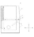
図1に示すように、原子吸光分光光度計10は、筒状の本体ケース1と筒状の煙突2を含み、煙突2は下部が本体ケース1の内部に挿入されるように本体ケース1に取り付けられる。
本体ケース1の左右方向の一対の本体ケース側壁の頂部には制限溝3が設置される。
制限溝3の数量と位置は、本体ケース1と煙突2の大きさ及び相対位置に応じて適合的に設置されてもよい。本発明に係る実施形態においては、図2に示すように、一方の側の本体ケース側壁には二つの制限溝3が設けられる。同様に、他方の側の本体ケース側壁にも二つの制限溝が設けられる(未図示)。
煙突2の本体ケース1に取り付けられる時に制限溝3に対応する位置には突出部4が設けられる。図2に示すように、一方の側の煙突側壁には二つの突出部4が設けられる。同様に、他方の側の煙突側壁にも二つの突出部が設けられる(未図示)。
煙突2を本体ケース1に取り付ける時に、突出部4が制限溝3内に嵌め込まれる。制限溝3と突出部4との嵌合によって、煙突2を安定に本体ケース1に取り付ける。
図1~図3は、本体ケース1に制限溝3を設けて、煙突2に突出部4を設ける実例を示す。ところが、煙突2の左右方向の一対の煙突側壁の底部には制限溝が設けられ、本体ケース1の煙突2が設けられる時に制限溝に対応する位置には突出部が設置されてもよい。煙突2を安定に本体ケース1に取り付けることもできる。
本発明に係る蝶番式連接棒5の煙突脱出構造は、一対の連接棒5を含み、図1~図3には一方の側の連接棒5のみが示されるが、実際には、他方の側の連接棒も、まったく同じ構造を有する。
一対の連接棒5の一端は、それぞれ一対の煙突側壁に回転可能に接続され、一対の連接棒5の他端は、夫々一対の本体ケース側壁に回転可能且つ移動可能に接続される。
具体的には、一対の本体ケース側壁における一対の連接棒5の他端に連続される位置には、それぞれ前後方向に延びる狭長な穴6が設けられ、一対の連接棒5の他端には、それぞれ回転軸7が設けられ、回転軸7が狭長な穴6内に係合されるとともに、回転軸7が狭長な穴6内に回転可能且つ前後に移動可能である。
煙突2が本体ケース1に取り付けられる時に、連接棒5は図1及び図2の破線で示す箇所に位置し、この時に、連接棒5の他端に設けられた回転軸7は狭長な穴6の前側に位置する。
煙突2を制限位置から脱出させると、煙突2を上昇させて、突出部4が制限溝3から離れるようにする。この時に、連接棒5の一端が煙突2に従って上方に移動して、連接棒5の他端に設けられた回転軸7が狭長な穴6の中で狭長な穴6の後側(図2の実線で示す連接棒5の位置)まで後方へ移動する。図3に示すように、突出部4が制限溝3から脱出してから、煙突2を回転軸7の周りに後方へ回転させて、最終的に煙突2を未図示の後方のブラケットに置く。本発明によれば、蝶番式連接棒5は干渉を受けず、煙突2が制限位置から脱出可能になり、後続の煙突2を回転して後方に置くという目的を達成することができる。
なお、本発明に係る連接棒5の形状は湾曲棒状であるが、これに限られない。直線状等その他の形状であっても良い。連接棒5の両端における煙突2及び本体ケース1との接続位置には、煙突2を安定に回転させるためのリングダンパーを設置してもよい。
1 本体ケース
2 煙突
3 制限溝
4 突出部
5 連接棒
6 狭長な穴
7 回転軸
10 原子吸光分光光度計
2 煙突
3 制限溝
4 突出部
5 連接棒
6 狭長な穴
7 回転軸
10 原子吸光分光光度計
Claims (4)
- 筒状の本体ケースと筒状の煙突とを含み、前記煙突は、下部が前記本体ケースの内部に挿入されるように前記本体ケースに取り付けられ、
前記本体ケースの左右方向の一対の本体ケース側壁の頂部には制限溝が設置され、且つ前記煙突の前記本体ケースに取り付けられる時に前記制限溝に対応する位置には突出部が設置され、又は、前記煙突の左右方向の一対の煙突側壁の底部には制限溝が設置され、前記本体ケースの前記煙突が設けられる時に前記制限溝に対応する位置には突出部が設置され、
前記煙突を前記本体ケースに取り付ける時に、前記突出部が前記制限溝内に嵌め込まれる原子吸光分光光度計に用いられる蝶番式連接棒の煙突脱出構造において、
前記蝶番式連接棒の煙突脱出構造は一対の連接棒を含み、前記一対の連接棒の一端は、それぞれ前記一対の煙突側壁に回転可能に接続され、前記一対の連接棒の他端は、夫々前記一対の本体ケース側壁に回転可能且つ移動可能に接続されることを特徴とする蝶番式連接棒の煙突脱出構造。 - 前記一対の本体ケース側壁における前記一対の連接棒の他端に連続される位置には、それぞれ前後方向に延びる狭長な穴が設けられ、前記一対の連接棒の他端には、それぞれ回転軸が設けられ、前記回転軸が前記狭長な穴内に係合されるとともに、前記回転軸が前記狭長な穴の内で回転可能且つ前後に移動可能であることを特徴とする請求項1に記載の蝶番式連接棒の煙突脱出構造。
- 筒状の本体ケースと筒状の煙突とを含み、前記煙突は、下部が前記本体ケースの内部に挿入されるように前記本体ケースに取り付けられ、
前記本体ケースの左右方向の一対の本体ケース側壁の頂部には制限溝が設置され、且つ前記煙突の前記本体ケースに取り付けられる時に前記制限溝に対応する位置には突出部が設置され、又は、前記煙突の左右方向の一対の煙突側壁の底部には制限溝が設置され、前記本体ケースの前記煙突が設けられる時に前記制限溝に対応する位置には突出部が設置され、前記煙突を前記本体ケースに取り付ける時に、前記突出部が前記制限溝内に嵌め込まれる原子吸光分光光度計において、
一対の連接棒を含み、前記一対の連接棒の一端が、それぞれ前記一対の煙突側壁に回転可能に接続され、前記一対の連接棒の他端が、夫々前記一対の本体ケース側壁に回転可能且つ移動可能に接続される蝶番式連接棒の煙突脱出構造を有することを特徴とする原子吸光分光光度計。 - 前記一対の本体ケース側壁における前記一対の連接棒の他端に連続される位置には、それぞれ前後方向に延びる狭長な穴が設けられ、前記一対の連接棒の他端には、それぞれ回転軸が設けられ、前記回転軸が前記狭長な穴内に係合されるとともに、前記回転軸が前記狭長な穴の内で回転可能且つ前後に移動可能であることを特徴とする請求項3に記載の原子吸光分光光度計。
Applications Claiming Priority (2)
| Application Number | Priority Date | Filing Date | Title |
|---|---|---|---|
| CN201821000218.7U CN208399385U (zh) | 2018-06-27 | 2018-06-27 | 铰链式连杆的烟囱脱出结构以及原子吸收分光光度计 |
| CN201821000218.7 | 2018-06-27 |
Publications (1)
| Publication Number | Publication Date |
|---|---|
| WO2020003623A1 true WO2020003623A1 (ja) | 2020-01-02 |
Family
ID=65132378
Family Applications (1)
| Application Number | Title | Priority Date | Filing Date |
|---|---|---|---|
| PCT/JP2019/009517 Ceased WO2020003623A1 (ja) | 2018-06-27 | 2019-03-08 | 蝶番式連接棒の煙突脱出構造及び原子吸光分光光度計 |
Country Status (2)
| Country | Link |
|---|---|
| CN (1) | CN208399385U (ja) |
| WO (1) | WO2020003623A1 (ja) |
Citations (4)
| Publication number | Priority date | Publication date | Assignee | Title |
|---|---|---|---|---|
| JPS62178353U (ja) * | 1986-04-30 | 1987-11-12 | ||
| JPH08201282A (ja) * | 1995-01-23 | 1996-08-09 | Hitachi Ltd | フレームレス原子吸光用原子化装置 |
| JP2008157772A (ja) * | 2006-12-25 | 2008-07-10 | Toppan Printing Co Ltd | プラスチック試料中金属元素の分析方法 |
| CN203744192U (zh) * | 2014-02-19 | 2014-07-30 | 浙江省海洋水产研究所 | 一种石墨炉原子吸收光谱仪照明装置 |
-
2018
- 2018-06-27 CN CN201821000218.7U patent/CN208399385U/zh not_active Expired - Fee Related
-
2019
- 2019-03-08 WO PCT/JP2019/009517 patent/WO2020003623A1/ja not_active Ceased
Patent Citations (4)
| Publication number | Priority date | Publication date | Assignee | Title |
|---|---|---|---|---|
| JPS62178353U (ja) * | 1986-04-30 | 1987-11-12 | ||
| JPH08201282A (ja) * | 1995-01-23 | 1996-08-09 | Hitachi Ltd | フレームレス原子吸光用原子化装置 |
| JP2008157772A (ja) * | 2006-12-25 | 2008-07-10 | Toppan Printing Co Ltd | プラスチック試料中金属元素の分析方法 |
| CN203744192U (zh) * | 2014-02-19 | 2014-07-30 | 浙江省海洋水产研究所 | 一种石墨炉原子吸收光谱仪照明装置 |
Also Published As
| Publication number | Publication date |
|---|---|
| CN208399385U (zh) | 2019-01-18 |
Similar Documents
| Publication | Publication Date | Title |
|---|---|---|
| US10822836B2 (en) | Electric lock device for opening and closing body | |
| US10738511B2 (en) | Locking device for opening/closing body | |
| US9121206B2 (en) | Locking device for closing-opening member | |
| US10480223B2 (en) | Lock device for opening and closing body | |
| EP1462713A2 (en) | Lighting device | |
| JPWO2017195557A1 (ja) | 開閉体のロック装置 | |
| CN103976692B (zh) | 伸缩管 | |
| IT9003391A1 (it) | Maniglia a cremonese mulitiuso per infissi. | |
| ATE326645T1 (de) | Verschlusssystem und kinderwagen mit einem solchen system | |
| WO2016150074A1 (zh) | 用于键盘和平板电脑的支撑机构 | |
| ITMI20080518A1 (it) | Gruppo porta gobos per un proiettore da palcoscenico e proiettore da palcoscenico provvisto di tale gruppo porta gobos | |
| CN110650868A (zh) | 车辆用灯具 | |
| JP3176136U (ja) | レジスタ | |
| US8171940B2 (en) | Rotary cutter assembly for a lighter | |
| JP6661864B2 (ja) | 伸縮装置 | |
| EP3460426A1 (en) | Spectrophotometer | |
| JP2005116953A (ja) | 蓋開閉機構及びその装置 | |
| KR101805053B1 (ko) | 레버형 손잡이 | |
| FI115949B (fi) | Järjestely komponenttien kiinnittämiseksi irrotettavasti runko-osaan | |
| JP6958288B2 (ja) | 赤外分光光度計及び窓部材の保管方法 | |
| JP4733866B2 (ja) | 投影レンズ装置及びこれを備えたスポットライト | |
| US6380519B1 (en) | Electrical oven having a housing with a turnable lid | |
| JP4374304B2 (ja) | 便座および便蓋の蝶着機構 | |
| JP5269545B2 (ja) | レジスタ | |
| JP2008184071A (ja) | 車輪止め構造 |
Legal Events
| Date | Code | Title | Description |
|---|---|---|---|
| 121 | Ep: the epo has been informed by wipo that ep was designated in this application |
Ref document number: 19825833 Country of ref document: EP Kind code of ref document: A1 |
|
| NENP | Non-entry into the national phase |
Ref country code: DE |
|
| 122 | Ep: pct application non-entry in european phase |
Ref document number: 19825833 Country of ref document: EP Kind code of ref document: A1 |
|
| NENP | Non-entry into the national phase |
Ref country code: JP |