WO2020003527A1 - 排煙脱硫装置 - Google Patents
排煙脱硫装置 Download PDFInfo
- Publication number
- WO2020003527A1 WO2020003527A1 PCT/JP2018/024918 JP2018024918W WO2020003527A1 WO 2020003527 A1 WO2020003527 A1 WO 2020003527A1 JP 2018024918 W JP2018024918 W JP 2018024918W WO 2020003527 A1 WO2020003527 A1 WO 2020003527A1
- Authority
- WO
- WIPO (PCT)
- Prior art keywords
- duct
- exhaust gas
- chimney
- bypass
- absorption tower
- Prior art date
- Legal status (The legal status is an assumption and is not a legal conclusion. Google has not performed a legal analysis and makes no representation as to the accuracy of the status listed.)
- Ceased
Links
Images

Classifications
-
- B—PERFORMING OPERATIONS; TRANSPORTING
- B01—PHYSICAL OR CHEMICAL PROCESSES OR APPARATUS IN GENERAL
- B01D—SEPARATION
- B01D53/00—Separation of gases or vapours; Recovering vapours of volatile solvents from gases; Chemical or biological purification of waste gases, e.g. engine exhaust gases, smoke, fumes, flue gases, aerosols
- B01D53/34—Chemical or biological purification of waste gases
- B01D53/46—Removing components of defined structure
- B01D53/48—Sulfur compounds
- B01D53/50—Sulfur oxides
-
- F—MECHANICAL ENGINEERING; LIGHTING; HEATING; WEAPONS; BLASTING
- F23—COMBUSTION APPARATUS; COMBUSTION PROCESSES
- F23J—REMOVAL OR TREATMENT OF COMBUSTION PRODUCTS OR COMBUSTION RESIDUES; FLUES
- F23J15/00—Arrangements of devices for treating smoke or fumes
Definitions
- the present invention relates to a flue gas desulfurization device used in a coal-fired power plant or the like.
- boilers such as coal-fired power plants generate exhaust gas by burning fuel.
- the exhaust gas contains dust and sulfur oxides. Therefore, the exhaust gas is discharged to the atmosphere from the chimney with the sulfur oxides reduced in the flue gas desulfurization device.
- the flue gas desulfurization device is provided with an absorption tower for removing sulfur oxides in exhaust gas.
- an exhaust liquid containing an absorbent such as limestone (calcium carbonate) or a slurry containing lime is sprayed on exhaust gas containing sulfur oxides entered from an inlet duct. Then, by bringing the exhaust gas into contact with the absorbing liquid, sulfur oxides in the exhaust gas are absorbed and removed. The desulfurized exhaust gas is discharged from the outlet duct of the absorption tower. The exhaust gas discharged from the outlet duct is released to the atmosphere from the chimney.
- an absorbent such as limestone (calcium carbonate) or a slurry containing lime
- Some of the flue gas desulfurization units have a bypass duct that discharges the exhaust gas without passing through the absorption tower in case the absorption tower is shut down or the exhaust gas cannot be accepted due to maintenance or the like.
- the exhaust gas flowing from the bypass duct to the downstream side is discharged to the atmosphere from the chimney through a merging duct provided between the outlet duct of the absorption tower and the chimney.
- the present invention provides a flue gas desulfurization apparatus having a main line for removing sulfur oxides of exhaust gas in an absorption tower and a bypass line for preventing exhaust gas from passing through the absorption tower, which reduces the cost and configuration required for a duct for passing exhaust gas. It is intended to simplify the above.
- the present invention provides an exhaust duct for removing the sulfur oxides in an absorption tower of a main line for removing sulfur oxides of exhaust gas, the outlet duct for flowing the exhaust gas downstream, and the exhaust gas to the absorption tower.
- the air conditioner includes a bypass duct of a bypass line that flows downstream without passing through the stack, and a chimney that discharges the exhaust gas to the atmosphere.
- the outlet duct and the bypass duct are directly connected to the chimney, respectively.
- outlet duct and the bypass duct may be connected to the chimney side by side in the vertical direction, and the outlet duct may be located below and the bypass duct may be located above.
- the drain pipe for discharging the moisture in the exhaust gas discharged from the absorption tower is shortened, and the drain pipe can be easily arranged.
- outlet duct and the bypass duct may be connected to the chimney side by side in the vertical direction, and the outlet duct may be located above and the bypass duct may be located below.
- the outlet duct having corrosion resistance is arranged in a large space above, and the outlet duct can be easily arranged.
- the exhaust gas desulfurized in the absorption tower and the exhaust gas passing through the bypass duct can be respectively discharged directly to the chimney. Therefore, a merging duct is not required, and only the outlet duct of the absorption tower needs to be provided with corrosion resistance, so that the cost and the configuration of the flue gas desulfurization device can be reduced.
- FIG. 1 is an equipment configuration diagram including a flue gas desulfurization device according to one embodiment of the present invention.
- FIG. 2 is a plan view of a part including an absorption tower and a chimney of the flue gas desulfurization apparatus shown in FIG.
- FIG. 3 is a side view of a portion including an outlet duct, a bypass duct, and a chimney of the absorption tower shown in FIG.
- FIG. 4 is a schematic diagram showing a connection portion between the outlet duct and the chimney of the bypass duct shown in FIG.
- FIG. 2 illustrates an example in which two flue gas desulfurization devices 5 are provided, but the same applies to a single flue gas desulfurization device.
- FIG. 1 is an equipment configuration diagram including a flue gas desulfurization device 5 according to one embodiment.
- Exhaust gas G containing sulfur oxides discharged from a boiler or the like (not shown) is subjected to dust removal by the dust collector 1.
- the exhaust gas G from which the dust has been removed is pressurized by the induction fan 2 and discharged from the exhaust gas duct 3.
- the exhaust gas G discharged from the exhaust gas duct 3 is introduced into the absorption tower 6 provided in the flue gas desulfurization device 5 from the inlet duct 4.
- the exhaust gas G is desulfurized by being brought into contact with the absorbing liquid sprayed inside the absorption tower 6.
- the exhaust gas G from which the sulfur oxides have been removed in the absorption tower 6 is removed by a mist eliminator 7 provided at the outlet.
- the exhaust gas G from which water has been removed is discharged from the outlet duct 8 and discharged to the atmosphere from the chimney 9. This is the main line.
- a bypass line is also provided that allows the exhaust gas G to flow from the exhaust gas duct 3 of the induction fan 2 to the chimney 9 via the bypass duct 10 and discharge to the atmosphere without passing through the absorption tower 6.
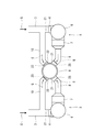
- FIG. 2 is a plan view of a portion including the absorption tower 6 and the chimney 9 of the flue gas desulfurization device 5.
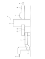
- FIG. 3 is a side view of a portion including the outlet duct 8, the bypass duct 10, and the chimney 9 of the absorption tower 6 shown in FIG.
- FIG. 2 shows an example in which two systems of flue gas desulfurization devices 5 are provided on the left and right. However, since they have the same configuration, only one will be described. Further, in the plan view of FIG. 2, an example in which the outlet duct 8 and the bypass duct 10 are arranged in a horizontal direction and connected to the chimney 9 will be described.
- the exhaust duct 3 of the induction fan 2 is provided with the inlet duct 4 of the absorption tower 6 so as to be continuous.
- An entrance damper 21 is provided on the side of the entrance duct 4 where the induction fan 2 is located.
- a bypass duct 10 is provided upstream of the inlet damper 21 so as to branch off from the exhaust gas duct 3.
- the bypass duct 10 extends to the chimney 9 and is connected to a bypass duct connecting portion 32 provided on a side surface of the chimney 9.
- a bypass damper 23 is provided at a portion of the bypass duct 10 connected to the bypass duct connection portion 32.
- the inlet damper 21 and the bypass damper 23 can open or close the flow path of each duct.
- the exhaust gas G entering the absorption tower 6 from the inlet duct 4 is desulfurized inside the absorption tower 6.
- Moisture is removed from the desulfurized exhaust gas G by a mist eliminator 7 provided at an outlet of the absorption tower 6.
- the exhaust gas G from which water has been removed exits the outlet duct 8.
- the outlet duct 8 extends to the chimney 9 and is connected to an outlet duct connection 31 provided on a side surface of the chimney 9.
- An outlet damper 25 is provided at a portion of the outlet duct 8 connected to the outlet duct connection portion 31.
- the outlet damper 25 can open or close the flow path of the outlet duct 8.
- the exhaust gas duct 3 from the dust collector 1 is sent to the exhaust fan 2 provided at a low position at an elevated pressure.
- the inlet duct 4 of the absorption tower 6 is provided at a high position.
- the connecting portion between the exhaust gas duct 3 and the inlet duct 4 is provided at a high position.
- the position where the exhaust gas G exits from the absorption tower 6 is high, and the mist eliminator 7 and the outlet duct 8 are provided at high positions.
- the bypass damper 23 is closed, and the inlet damper 21 and the outlet damper 25 are opened. .
- the exhaust gas G is introduced from the exhaust gas duct 3 into the absorption tower 6 via the inlet duct 4.
- the exhaust gas G desulfurized in the absorption tower 6 is discharged to a chimney 9 via a mist eliminator 7 and an outlet duct 8 and discharged to the atmosphere.
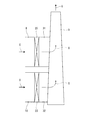
- FIG. 4 is a schematic diagram showing a connection portion between the outlet duct 8 and the chimney 9 of the bypass duct 10 shown in FIG.
- the outlet duct 8 and the bypass duct 10 are arranged vertically and connected to the chimney 9.
- the outlet duct 8 is connected to the chimney 9 such that the outlet duct 8 is located above and the bypass duct 10 is located below.
- the chimney 9 is provided with the outlet duct connection part 31 and the bypass duct connection part 32. Since the inner surfaces of the outlet duct connection portion 31 and the bypass duct connection portion 32 communicate with the inside of the chimney 9, the exhaust duct G is provided with heat resistance and corrosion resistance.
- an expensive material for example, Hastelloy (registered trademark) obtained by adding a large amount of molybdenum or chromium to a nickel base is used.
- Hastelloy registered trademark
- a portion of the second outlet damper 25 is directly connected to the outlet duct connection part 31.
- a portion of the bypass outlet damper 23 is directly connected to the bypass duct connection portion 32.
- the outlet duct 8 may be connected to the chimney 9 so that the outlet duct 8 is located below and the bypass duct 10 is located above.
- an outlet duct 8 provided with a drain pipe for discharging moisture in the exhaust gas G discharged from the absorption tower 6 is located below. Therefore, the drain pipe is shortened, and the drain pipe can be easily arranged.
- outlet duct 8 and the bypass duct 10 are arranged vertically, the outlet duct 8 is located above, and the bypass duct 10 is located below.
- the outlet duct 8 and the bypass duct 10 may be arranged side by side in the horizontal direction.
- the outlet duct 8 and the bypass duct 10 may be directly connected to the chimney 9 and may be arranged at any position around the chimney 9.
- the arrangement for connecting the outlet duct 8 and the bypass duct 10 to the chimney 9 is the same as in the above embodiment. It is not limited to.
- the above-described embodiment shows an example, and various changes can be made without departing from the scope of the present invention.
- the sizes of the outlet duct 8 and the bypass duct 10 are merely examples, and the present invention is not limited thereto.
- Various configurations may be changed without impairing the gist, and the present invention is not limited to the above embodiment.
Landscapes
- Engineering & Computer Science (AREA)
- Chemical & Material Sciences (AREA)
- General Chemical & Material Sciences (AREA)
- Environmental & Geological Engineering (AREA)
- Biomedical Technology (AREA)
- Analytical Chemistry (AREA)
- Health & Medical Sciences (AREA)
- Oil, Petroleum & Natural Gas (AREA)
- Chemical Kinetics & Catalysis (AREA)
- Mechanical Engineering (AREA)
- General Engineering & Computer Science (AREA)
- Treating Waste Gases (AREA)
- Chimneys And Flues (AREA)
Abstract
排ガスの硫黄酸化物を除去するメインラインの吸収塔において硫黄酸化物を除去した排ガスを下流側に流す出口ダクトと、排ガスを吸収塔に通さずに下流側に流すバイパスラインのバイパスダクトと、排ガスを大気放出する煙突と、を備え、出口ダクトとバイパスダクトとは、煙突にそれぞれ直接接続されている。これにより、排煙脱硫装置における排ガスを通過させるダクトに要する費用削減と構成の簡略化を図る。
Description
本発明は、石炭火力発電所などで使用される排煙脱硫装置に関する。
従来、石炭火力発電プラントなどのボイラは、燃料を燃焼させることで排ガスが発生する。排ガスには、煤塵や硫黄酸化物などが含まれる。そのため、排ガスは排煙脱硫装置において硫黄酸化物が低減されて煙突から大気放出される。排煙脱硫装置には、排ガス中の硫黄酸化物を除去する吸収塔が備えられている。
吸収塔では、入口ダクトから入った硫黄酸化物を含む排ガスに対して、石灰石(炭酸カルシウム)又は石灰を含むスラリ等の吸収剤を含んだ吸収液が噴霧される。そして、排ガスと吸収液とを接触させることにより、排ガス中の硫黄酸化物が吸収除去される。脱硫処理された排ガスは、吸収塔の出口ダクトから排出される。出口ダクトから排出された排ガスは、煙突から大気放出される。
また、排煙脱硫装置には、吸収塔が緊急停止した場合やメンテナンスなどで排ガスを受け入れられない場合に備えて、排ガスを吸収塔を通さずに排出させるバイパスダクトを有するものがある。バイパスダクトから下流側に流された排ガスは、吸収塔の出口ダクトと煙突との間に設けられた合流ダクトを通って煙突から大気放出される。
この種の先行技術として、例えば、排ガスを吸収塔に入れて硫黄酸化物を除去するラインと、排ガスを吸収塔に入れずにバイパスダクトを通過させるラインとを設けた湿式排ガス脱硫装置がある(例えば、特許文献1参照)。この装置では、吸収塔で硫黄酸化物を除去した脱硫処理排ガスと、バイパスダクトを通過させたバイパス排ガスとを、混合機において効率良く混合させている。
しかし、上記先行技術では、吸収塔で脱硫処理された低温で水分飽和の状態となった腐食性の強い脱硫処理排ガスと、バイパスダクトを通過させた高温の排ガスとを混合器で混合している。このため、耐食性の高い高価な混合器が必要となる。また、混合器を出た排ガスも腐食性を有しているため、混合器と煙突とを接続する接続ダクトにも耐食性や耐熱性の高い材料を用いる必要がある。耐食性、耐熱性の高い材料として、例えば、ニッケル基にモリブデンやクロムを多く加えた高価な材料(例えば、ハステロイ(登録商標))を用いる必要があり、多くの費用を要する。
そこで、本発明は、吸収塔において排ガスの硫黄酸化物を除去するメインラインと、吸収塔に排ガスを通さないバイパスラインとを有する排煙脱硫装置において、排ガスを通過させるダクトに要する費用削減と構成の簡略化を図ることを目的とする。
上記目的を達成するために、本発明は、排ガスの硫黄酸化物を除去するメインラインの吸収塔において硫黄酸化物を除去した前記排ガスを下流側に流す出口ダクトと、前記排ガスを前記吸収塔に通さずに下流側に流すバイパスラインのバイパスダクトと、前記排ガスを大気放出する煙突と、を備え、前記出口ダクトと前記バイパスダクトとは、前記煙突にそれぞれ直接接続されている。
この構成により、吸収塔において脱硫された排ガスは、煙突に直接排出される。バイパスダクトを通過させる排ガスも、煙突に直接排出される。よって、吸収塔と煙突とを接続する出口ダクトにのみ耐食性を備えさせればよくなり、構成の簡略化を図ることができる。しかも、合流ダクトが不要となり、合流ダクトに耐食性を備えさせるためのコストを削減することができる。
また、前記出口ダクトと前記バイパスダクトとは上下方向に並んで前記煙突に接続されており、前記出口ダクトが下方に位置し、前記バイパスダクトが上方に位置するように接続されていてもよい。
このように構成すれば、吸収塔から排出される排ガス中の水分を排出するドレン配管が短くなり、ドレン配管を容易に配置することができる。
また、前記出口ダクトと前記バイパスダクトとは上下方向に並んで前記煙突に接続されており、前記出口ダクトが上方に位置し、前記バイパスダクトが下方に位置するように接続されていてもよい。
このように構成すれば、耐食性を備えさせる出口ダクトを上方の広い空間で配置することになり、出口ダクトを容易に配置することができる。
本発明によれば、吸収塔において脱硫された排ガスと、バイパスダクトを通過させる排ガスとを、それぞれ煙突に直接排出することができる。よって、合流ダクトが不要となり、吸収塔の出口ダクトにのみ耐食性を備えさせればよく、排煙脱硫装置のコスト削減と構成の簡略化を図ることが可能となる。
以下、本発明の実施形態を図面に基づいて説明する。以下の実施形態では、排ガスGの流れる方向に基づいて、上流側又は下流側という。また、図2では、2系統の排煙脱硫装置5が備えられた例を説明するが、1系統の排煙脱硫装置でも同様である。
(排煙脱硫装置を含む設備構成)
図1は、一実施形態に係る排煙脱硫装置5を含む設備構成図である。図示しないボイラなどから排出される硫黄酸化物を含む排ガスGは、集塵器1によって煤塵が除去される。煤塵が除去された排ガスGは、誘引ファン2で昇圧されて排ガスダクト3から排出される。排ガスダクト3から排出された排ガスGは、排煙脱硫装置5に備えられた吸収塔6に、入口ダクト4から入れられる。排ガスGは、吸収塔6の内部で噴霧されている吸収液と接触させられることで脱硫される。吸収塔6で硫黄酸化物が除去された排ガスGは、出口に設けられたミストエリミネータ7によって水分が除去される。水分が除去された排ガスGは、出口ダクト8から排出されて煙突9から大気放出される。これがメインラインである。また、排ガスGを吸収塔6に通さずに、誘引ファン2の排ガスダクト3からバイパスダクト10を介して煙突9へ流して大気放出するバイパスラインも備えられている。
図1は、一実施形態に係る排煙脱硫装置5を含む設備構成図である。図示しないボイラなどから排出される硫黄酸化物を含む排ガスGは、集塵器1によって煤塵が除去される。煤塵が除去された排ガスGは、誘引ファン2で昇圧されて排ガスダクト3から排出される。排ガスダクト3から排出された排ガスGは、排煙脱硫装置5に備えられた吸収塔6に、入口ダクト4から入れられる。排ガスGは、吸収塔6の内部で噴霧されている吸収液と接触させられることで脱硫される。吸収塔6で硫黄酸化物が除去された排ガスGは、出口に設けられたミストエリミネータ7によって水分が除去される。水分が除去された排ガスGは、出口ダクト8から排出されて煙突9から大気放出される。これがメインラインである。また、排ガスGを吸収塔6に通さずに、誘引ファン2の排ガスダクト3からバイパスダクト10を介して煙突9へ流して大気放出するバイパスラインも備えられている。
(排煙脱硫装置の吸収塔と煙突を含む部分の構成)
図2は、排煙脱硫装置5の吸収塔6と煙突9を含む部分の平面図である。図3は、図2に示す吸収塔6の出口ダクト8とバイパスダクト10と煙突9を含む部分の側面図である。図2では、左右に2系統の排煙脱硫装置5を備えた例を示しているが、同一の構成であるため、一方を説明する。また、図2の平面図では、出口ダクト8とバイパスダクト10とを水平方向に並べて煙突9に接続した例を説明する。
図2は、排煙脱硫装置5の吸収塔6と煙突9を含む部分の平面図である。図3は、図2に示す吸収塔6の出口ダクト8とバイパスダクト10と煙突9を含む部分の側面図である。図2では、左右に2系統の排煙脱硫装置5を備えた例を示しているが、同一の構成であるため、一方を説明する。また、図2の平面図では、出口ダクト8とバイパスダクト10とを水平方向に並べて煙突9に接続した例を説明する。
誘引ファン2の排ガスダクト3には、吸収塔6の入口ダクト4が連なるように設けられている。入口ダクト4の誘引ファン2側には、入口ダンパ21が設けられている。入口ダンパ21の上流側には、排ガスダクト3から分岐するようにバイパスダクト10が設けられている。バイパスダクト10は、煙突9へと延びており、煙突9の側面に設けられたバイパスダクト接続部32に接続されている。バイパスダクト10のバイパスダクト接続部32と接続する部分には、バイパスダンパ23が設けられている。入口ダンパ21、バイパスダンパ23は、各ダクトの流路を開放又は閉鎖することができる。
一方、入口ダクト4から吸収塔6に入った排ガスGは、吸収塔6の内部で脱硫される。脱硫された排ガスGは、吸収塔6の出口部分に設けられたミストエリミネータ7によって水分が除去される。水分が除去された排ガスGは、出口ダクト8から出る。出口ダクト8は、煙突9へと延びており、煙突9の側面に設けられた出口ダクト接続部31に接続されている。出口ダクト8の出口ダクト接続部31と接続する部分には、出口ダンパ25が設けられている。出口ダンパ25は、出口ダクト8の流路を開放又は閉鎖することができる。
図3に示すように、集塵器1からの排ガスダクト3は、低い位置に設けられた誘引ファン2で昇圧されて送られる。一方、吸収塔6の入口ダクト4は高い位置に設けられている。このため、排ガスダクト3と入口ダクト4との接続部分は、高い位置に設けられている。また、吸収塔6から排ガスGが出る位置も高く、ミストエリミネータ7と出口ダクト8とは高い位置に設けられている。
このように構成された排煙脱硫装置5によれば、図2に示すように、排ガスGを吸収塔6に通す場合、バイパスダンパ23が閉鎖され、入口ダンパ21及び出口ダンパ25が開放される。これにより、排ガスGは、排ガスダクト3から入口ダクト4を介して吸収塔6に入れられる。吸収塔6で脱硫された排ガスGは、ミストエリミネータ7と出口ダクト8を介して煙突9に排出されて大気放出される。
一方、排ガスGを吸収塔6に通さない場合、バイパスダンパ23が開放され、入口ダンパ21及び出口ダンパ25が閉鎖される。これにより、排ガスGは、排ガスダクト3からバイパスダクト10を介して煙突9に排出されて大気放出される。
(出口ダクト及びバイパスダクトと煙突の接続構造)
図4は、図2に示す出口ダクト8とバイパスダクト10の煙突9との接続部分を示す模式図である。図4に示す例では、出口ダクト8とバイパスダクト10とが上下方向に配置されて煙突9に接続されている。この例では、出口ダクト8が上方に位置し、バイパスダクト10が下方に位置するように煙突9に接続されている。煙突9には、上記出口ダクト接続部31と上記バイパスダクト接続部32とが設けられている。出口ダクト接続部31とバイパスダクト接続部32の内面は煙突9の内部に連通しているため、排ガスGに対する耐熱性及び耐食性が備えられている。出口ダクト接続部31とバイパスダクト接続部32との内面には、例えば、ニッケル基にモリブデンやクロムを多く加えた高価な材料(例えば、ハステロイ(登録商標))が用いられる。出口ダクト8は、第2出口ダンパ25の部分が出口ダクト接続部31に直接接続されている。バイパスダクト10は、バイパス出口ダンパ23の部分がバイパスダクト接続部32に直接接続されている。
図4は、図2に示す出口ダクト8とバイパスダクト10の煙突9との接続部分を示す模式図である。図4に示す例では、出口ダクト8とバイパスダクト10とが上下方向に配置されて煙突9に接続されている。この例では、出口ダクト8が上方に位置し、バイパスダクト10が下方に位置するように煙突9に接続されている。煙突9には、上記出口ダクト接続部31と上記バイパスダクト接続部32とが設けられている。出口ダクト接続部31とバイパスダクト接続部32の内面は煙突9の内部に連通しているため、排ガスGに対する耐熱性及び耐食性が備えられている。出口ダクト接続部31とバイパスダクト接続部32との内面には、例えば、ニッケル基にモリブデンやクロムを多く加えた高価な材料(例えば、ハステロイ(登録商標))が用いられる。出口ダクト8は、第2出口ダンパ25の部分が出口ダクト接続部31に直接接続されている。バイパスダクト10は、バイパス出口ダンパ23の部分がバイパスダクト接続部32に直接接続されている。
このように出口ダクト8とバイパスダクト10とを煙突9に直接接続することで、吸収塔6から排出された腐食性の強い排ガスGは出口ダクト8から煙突9に直接排出される。よって、出口ダクト8の下流に設ける構成と、その腐食対策が不要となる。
また、図4のように、出口ダクト8が上方でバイパスダクト10が下方となるように煙突9に接続すれば、図3に示すように、吸収塔6から高い位置で排出される排ガスGを排出する出口ダクト8と、誘引ファン2から低い位置で排ガスGを送る排ガスダクト3に連なるバイパスダクト10の位置関係を保てる。よって、出口ダクト8とバイパスダクト10を容易に煙突9に接続することができる。
一方、図4の配置とは逆に、出口ダクト8が下方でバイパスダクト10が上方となるように煙突9に接続してもよい。このように接続すれば、吸収塔6から排出される排ガスG中の水分を排出するドレン配管を設ける出口ダクト8が下方に位置する。よって、ドレン配管が短くなり、ドレン配管を容易に配置することができる。
(総括)
以上のように、上記排煙脱硫装置5によれば、吸収塔6の出口ダクト8とバイパスダクト10とを、それぞれ煙突9に直接接続することで、出口ダクト8とバイパスダクト10とを接続する合流ダクトが不要になる。しかも、合流ダクトに要する腐食対策及び耐熱対策も不要になるので、排煙脱硫装置5に要するコストと労力の削減を図ることが可能となる。
以上のように、上記排煙脱硫装置5によれば、吸収塔6の出口ダクト8とバイパスダクト10とを、それぞれ煙突9に直接接続することで、出口ダクト8とバイパスダクト10とを接続する合流ダクトが不要になる。しかも、合流ダクトに要する腐食対策及び耐熱対策も不要になるので、排煙脱硫装置5に要するコストと労力の削減を図ることが可能となる。
(その他の変形例)
図4に示す実施形態では、上下方向に出口ダクト8とバイパスダクト10を配置し、出口ダクト8を上方に位置させ、バイパスダクト10を下方に位置させた例を示しているが、図2に示すように出口ダクト8とバイパスダクト10とを水平方向に並べて配置してもよい。出口ダクト8とバイパスダクト10は、煙突9へ直接接続すればよく、煙突9の周囲のどの位置に配置してもよく、出口ダクト8とバイパスダクト10を煙突9に接続する配置は上記実施形態に限定されるものではない。
図4に示す実施形態では、上下方向に出口ダクト8とバイパスダクト10を配置し、出口ダクト8を上方に位置させ、バイパスダクト10を下方に位置させた例を示しているが、図2に示すように出口ダクト8とバイパスダクト10とを水平方向に並べて配置してもよい。出口ダクト8とバイパスダクト10は、煙突9へ直接接続すればよく、煙突9の周囲のどの位置に配置してもよく、出口ダクト8とバイパスダクト10を煙突9に接続する配置は上記実施形態に限定されるものではない。
また、上記した実施形態は一例を示しており、本発明の要旨を損なわない範囲での種々の変更は可能であり、出口ダクト8及びバイパスダクト10の大きさなどは一例であり、本発明の要旨を損なわない範囲での種々の構成を変更してもよく、本発明は上記した実施形態に限定されるものではない。
1 集塵器
2 誘引ファン
3 排ガスダクト
4 入口ダクト
5 排煙脱硫装置
6 吸収塔
7 ミストエリミネータ
8 出口ダクト
9 煙突
10 バイパスダクト
21 入口ダンパ
23 バイパスダンパ
25 出口ダンパ
31 出口ダクト接続部
32 バイパスダクト接続部
2 誘引ファン
3 排ガスダクト
4 入口ダクト
5 排煙脱硫装置
6 吸収塔
7 ミストエリミネータ
8 出口ダクト
9 煙突
10 バイパスダクト
21 入口ダンパ
23 バイパスダンパ
25 出口ダンパ
31 出口ダクト接続部
32 バイパスダクト接続部
Claims (3)
- 排ガスの硫黄酸化物を除去するメインラインの吸収塔において硫黄酸化物を除去した前記排ガスを下流側に流す出口ダクトと、
前記排ガスを前記吸収塔に通さずに下流側に流すバイパスラインのバイパスダクトと、
前記排ガスを大気放出する煙突と、を備え、
前記出口ダクトと前記バイパスダクトとは、前記煙突にそれぞれ直接接続されている、
ことを特徴とする排煙脱硫装置。 - 前記出口ダクトと前記バイパスダクトとは上下方向に並んで前記煙突に接続されており、
前記出口ダクトが下方に位置し、前記バイパスダクトが上方に位置するように接続されている、
請求項1に記載の排煙脱硫装置。 - 前記出口ダクトと前記バイパスダクトとは上下方向に並んで前記煙突に接続されており、
前記出口ダクトが上方に位置し、前記バイパスダクトが下方に位置するように接続されている、
請求項1に記載の排煙脱硫装置。
Priority Applications (2)
| Application Number | Priority Date | Filing Date | Title |
|---|---|---|---|
| JP2020527157A JPWO2020003527A1 (ja) | 2018-06-29 | 2018-06-29 | 排煙脱硫装置 |
| PCT/JP2018/024918 WO2020003527A1 (ja) | 2018-06-29 | 2018-06-29 | 排煙脱硫装置 |
Applications Claiming Priority (1)
| Application Number | Priority Date | Filing Date | Title |
|---|---|---|---|
| PCT/JP2018/024918 WO2020003527A1 (ja) | 2018-06-29 | 2018-06-29 | 排煙脱硫装置 |
Publications (1)
| Publication Number | Publication Date |
|---|---|
| WO2020003527A1 true WO2020003527A1 (ja) | 2020-01-02 |
Family
ID=68984799
Family Applications (1)
| Application Number | Title | Priority Date | Filing Date |
|---|---|---|---|
| PCT/JP2018/024918 Ceased WO2020003527A1 (ja) | 2018-06-29 | 2018-06-29 | 排煙脱硫装置 |
Country Status (2)
| Country | Link |
|---|---|
| JP (1) | JPWO2020003527A1 (ja) |
| WO (1) | WO2020003527A1 (ja) |
Citations (5)
| Publication number | Priority date | Publication date | Assignee | Title |
|---|---|---|---|---|
| JPS513372A (ja) * | 1974-06-24 | 1976-01-12 | Shuupiariaa Oiru Co Za | |
| JPS53122342U (ja) * | 1977-03-09 | 1978-09-29 | ||
| JPS59217414A (ja) * | 1983-05-25 | 1984-12-07 | Babcock Hitachi Kk | 排ガス処理装置 |
| JP2001038146A (ja) * | 1999-07-29 | 2001-02-13 | Babcock Hitachi Kk | 湿式排煙脱硫装置とその運転方法 |
| CN105688636A (zh) * | 2016-03-14 | 2016-06-22 | 张瀚镕 | 一种液化氨燃料 |
-
2018
- 2018-06-29 JP JP2020527157A patent/JPWO2020003527A1/ja active Pending
- 2018-06-29 WO PCT/JP2018/024918 patent/WO2020003527A1/ja not_active Ceased
Patent Citations (5)
| Publication number | Priority date | Publication date | Assignee | Title |
|---|---|---|---|---|
| JPS513372A (ja) * | 1974-06-24 | 1976-01-12 | Shuupiariaa Oiru Co Za | |
| JPS53122342U (ja) * | 1977-03-09 | 1978-09-29 | ||
| JPS59217414A (ja) * | 1983-05-25 | 1984-12-07 | Babcock Hitachi Kk | 排ガス処理装置 |
| JP2001038146A (ja) * | 1999-07-29 | 2001-02-13 | Babcock Hitachi Kk | 湿式排煙脱硫装置とその運転方法 |
| CN105688636A (zh) * | 2016-03-14 | 2016-06-22 | 张瀚镕 | 一种液化氨燃料 |
Also Published As
| Publication number | Publication date |
|---|---|
| JPWO2020003527A1 (ja) | 2021-07-01 |
Similar Documents
| Publication | Publication Date | Title |
|---|---|---|
| CN110036238B (zh) | 用于改善锅炉有效度的方法和系统 | |
| JP6852958B2 (ja) | 廃水を蒸発させかつ酸性気体排出を低減する装置および方法 | |
| KR100612534B1 (ko) | 배기가스 처리장치와 그 운용방법 | |
| JP2016120480A (ja) | 湿式排煙脱硫装置の廃水からのガス排出を低減するためのシステム及び方 | |
| JP6666231B2 (ja) | 噴霧乾燥システム | |
| JPS5828514B2 (ja) | ユウガイブツシツガンユウリヨウノスクナイハイガスオ タイキチユウヘドウシユツスルホウホウ オヨビ ソウチ | |
| CN207196530U (zh) | 一种用于消除锅炉烟囱白色烟羽的装置 | |
| CN203990298U (zh) | 一种火力发电用脱硫系统 | |
| JP5859244B2 (ja) | 排煙処理設備と排煙処理方法 | |
| JPWO2020003527A1 (ja) | 排煙脱硫装置 | |
| JPS6084131A (ja) | 排煙処理方法及び装置 | |
| KR19980032281A (ko) | 회전 재생식 열교환기에 의한 배기 가스 처리 장치 | |
| KR200325042Y1 (ko) | 스펙타클 플랜지 | |
| KR101839829B1 (ko) | 배출가스처리장치용 필터 및 배출가스처리장치 | |
| KR101974003B1 (ko) | 우회배관이 구비된 탈황설비의 재열기 | |
| US3791103A (en) | Method of treating waste gas arising from industrial facility | |
| JPS6223423A (ja) | 湿式排煙脱硫装置の制御方法 | |
| KR100621751B1 (ko) | 열교환 기능을 구비한 탈황설비의 덕트배치구조 | |
| WO2021009827A1 (ja) | 排煙脱硫装置 | |
| JP3408845B2 (ja) | 排ガス浄化装置とその運転方法 | |
| KR20100004661A (ko) | 배연 탈황 설비용 솔레노이드 밸브 | |
| CN204865488U (zh) | 一种臭氧均布器 | |
| US8882896B2 (en) | Multi-directional outlet transition and hood | |
| JPS6227209Y2 (ja) | ||
| CN213120123U (zh) | 一种脱硫脱硝烟气循环系统 |
Legal Events
| Date | Code | Title | Description |
|---|---|---|---|
| 121 | Ep: the epo has been informed by wipo that ep was designated in this application |
Ref document number: 18925035 Country of ref document: EP Kind code of ref document: A1 |
|
| ENP | Entry into the national phase |
Ref document number: 2020527157 Country of ref document: JP Kind code of ref document: A |
|
| NENP | Non-entry into the national phase |
Ref country code: DE |
|
| 122 | Ep: pct application non-entry in european phase |
Ref document number: 18925035 Country of ref document: EP Kind code of ref document: A1 |