WO2020003489A1 - 空気調和機 - Google Patents
空気調和機 Download PDFInfo
- Publication number
- WO2020003489A1 WO2020003489A1 PCT/JP2018/024780 JP2018024780W WO2020003489A1 WO 2020003489 A1 WO2020003489 A1 WO 2020003489A1 JP 2018024780 W JP2018024780 W JP 2018024780W WO 2020003489 A1 WO2020003489 A1 WO 2020003489A1
- Authority
- WO
- WIPO (PCT)
- Prior art keywords
- drain pan
- air conditioner
- contaminant
- ultrasonic
- drain
- Prior art date
- Legal status (The legal status is an assumption and is not a legal conclusion. Google has not performed a legal analysis and makes no representation as to the accuracy of the status listed.)
- Ceased
Links
Images






Classifications
-
- G—PHYSICS
- G01—MEASURING; TESTING
- G01N—INVESTIGATING OR ANALYSING MATERIALS BY DETERMINING THEIR CHEMICAL OR PHYSICAL PROPERTIES
- G01N29/00—Investigating or analysing materials by the use of ultrasonic, sonic or infrasonic waves; Visualisation of the interior of objects by transmitting ultrasonic or sonic waves through the object
- G01N29/02—Analysing fluids
- G01N29/032—Analysing fluids by measuring attenuation of acoustic waves
-
- F—MECHANICAL ENGINEERING; LIGHTING; HEATING; WEAPONS; BLASTING
- F24—HEATING; RANGES; VENTILATING
- F24F—AIR-CONDITIONING; AIR-HUMIDIFICATION; VENTILATION; USE OF AIR CURRENTS FOR SCREENING
- F24F11/00—Control or safety arrangements
- F24F11/30—Control or safety arrangements for purposes related to the operation of the system, e.g. for safety or monitoring
-
- F—MECHANICAL ENGINEERING; LIGHTING; HEATING; WEAPONS; BLASTING
- F24—HEATING; RANGES; VENTILATING
- F24F—AIR-CONDITIONING; AIR-HUMIDIFICATION; VENTILATION; USE OF AIR CURRENTS FOR SCREENING
- F24F11/00—Control or safety arrangements
- F24F11/89—Arrangement or mounting of control or safety devices
-
- F—MECHANICAL ENGINEERING; LIGHTING; HEATING; WEAPONS; BLASTING
- F24—HEATING; RANGES; VENTILATING
- F24F—AIR-CONDITIONING; AIR-HUMIDIFICATION; VENTILATION; USE OF AIR CURRENTS FOR SCREENING
- F24F13/00—Details common to, or for air-conditioning, air-humidification, ventilation or use of air currents for screening
- F24F13/22—Means for preventing condensation or evacuating condensate
- F24F13/222—Means for preventing condensation or evacuating condensate for evacuating condensate
-
- G—PHYSICS
- G01—MEASURING; TESTING
- G01N—INVESTIGATING OR ANALYSING MATERIALS BY DETERMINING THEIR CHEMICAL OR PHYSICAL PROPERTIES
- G01N17/00—Investigating resistance of materials to the weather, to corrosion, or to light
- G01N17/008—Monitoring fouling
-
- G—PHYSICS
- G01—MEASURING; TESTING
- G01S—RADIO DIRECTION-FINDING; RADIO NAVIGATION; DETERMINING DISTANCE OR VELOCITY BY USE OF RADIO WAVES; LOCATING OR PRESENCE-DETECTING BY USE OF THE REFLECTION OR RERADIATION OF RADIO WAVES; ANALOGOUS ARRANGEMENTS USING OTHER WAVES
- G01S15/00—Systems using the reflection or reradiation of acoustic waves, e.g. sonar systems
- G01S15/02—Systems using the reflection or reradiation of acoustic waves, e.g. sonar systems using reflection of acoustic waves
- G01S15/04—Systems determining presence of a target
-
- G—PHYSICS
- G01—MEASURING; TESTING
- G01N—INVESTIGATING OR ANALYSING MATERIALS BY DETERMINING THEIR CHEMICAL OR PHYSICAL PROPERTIES
- G01N2291/00—Indexing codes associated with group G01N29/00
- G01N2291/02—Indexing codes associated with the analysed material
- G01N2291/025—Change of phase or condition
- G01N2291/0256—Adsorption, desorption, surface mass change, e.g. on biosensors
-
- G—PHYSICS
- G01—MEASURING; TESTING
- G01N—INVESTIGATING OR ANALYSING MATERIALS BY DETERMINING THEIR CHEMICAL OR PHYSICAL PROPERTIES
- G01N2291/00—Indexing codes associated with group G01N29/00
- G01N2291/02—Indexing codes associated with the analysed material
- G01N2291/025—Change of phase or condition
- G01N2291/0258—Structural degradation, e.g. fatigue of composites, ageing of oils
-
- G—PHYSICS
- G01—MEASURING; TESTING
- G01N—INVESTIGATING OR ANALYSING MATERIALS BY DETERMINING THEIR CHEMICAL OR PHYSICAL PROPERTIES
- G01N2291/00—Indexing codes associated with group G01N29/00
- G01N2291/04—Wave modes and trajectories
- G01N2291/044—Internal reflections (echoes), e.g. on walls or defects
Definitions
- the present invention relates to an air conditioner, and more particularly, to an air conditioner that detects contaminants generated in a drain pan.
- a probe of an ultrasonic flaw detector is applied to a point on the outer periphery of a test tube, and an echo from the pipe body and an echo from the surface of a marine organism are measured.
- a measuring method is known in which the propagation distance of an echo from a biological surface is read and the attached thickness of a marine organism is measured (for example, see Patent Document 1).
- the ultrasonic wave is emitted from the direction perpendicular to the contact surface with the lining member, the reflected wave from the contact surface is received, and the thickness of the lining member is measured together with the degree of adhesion
- a possible inspection method is known (for example, see Patent Document 2).
- the thickness and the degree of adhesion of the attached matter are measured, and the method is applied to contaminants such as biofilms generated on a drain pan of an air conditioner.
- the motivation applied to the detection of is not disclosed or suggested in these documents.
- the biofilm is a semi-solid slime generated by the propagation of microorganisms in water stored in a drain pan or the like. Properties such as thickness and size of contaminants such as biofilms vary. Contaminants such as biofilms may clog drain pumps or drain hoses, and the presence of contaminants such as biofilms is not preferable in terms of sanitation. Drain pans are also called drain receivers and are subject to legal inspections under the Building Sanitation Law.
- the drain pan is integrally formed with a drain pump or the like inside the air conditioner, and it is necessary to disassemble the air conditioner for cleaning and maintenance. Therefore, for example, if an air conditioner is arranged behind a ceiling, cleaning, maintenance, and the like require much labor and cost.
- the present invention solves the above-described problems, and can improve the accuracy of detecting the presence or absence of a contaminant even if the air conditioner is affected by the properties of the contaminant formed on a drain pan. Is provided.
- the air conditioner according to the present invention has a drain pan for receiving water and an ultrasonic sensor for transmitting and receiving ultrasonic waves, and detects a contaminant generated in the drain pan by analyzing a response signal of the ultrasonic sensor.
- a bottom flat part forming the bottom of the drain pan and a flat part forming the receiving surface of the ultrasonic sensor are arranged in parallel.
- the bottom flat part forming the bottom of the drain pan and the flat part forming the receiving surface of the ultrasonic sensor are arranged in parallel. Therefore, the detection unit identifies the presence or absence of the contaminant based on the reflected sound of the ultrasonic wave from the contaminant a plurality of times, so that the detection accuracy of the contaminant is improved as compared with the identification based on the single reflected sound of the ultrasonic wave. I do.
- FIG. 2 is a schematic diagram showing a cross section of the air conditioner according to Embodiment 1 of the present invention.
- FIG. 2 is a schematic diagram showing a cross section around a drain pan of the air conditioner according to Embodiment 1 of the present invention.
- FIG. 3 is a schematic diagram illustrating an ultrasonic sensor of a detection unit in FIG. 2.
- FIG. 4 is a schematic diagram illustrating another example of the ultrasonic sensor of the detection unit in FIG. 2.
- FIG. 3 is a diagram showing an overall flow of operation by the air conditioner 100 according to Embodiment 1 of the present invention.
- FIG. 2 is a schematic diagram showing a cross section around a drain pan during a humidifying operation or a cooling operation of the air conditioner according to Embodiment 1 of the present invention.
- FIG. 3 is a graph showing a response of an ultrasonic wave when the drain pan shown in FIG. 2 is clean. 3 is a graph showing an ultrasonic response in a drain pan on which the contaminant shown in FIG. 2 is formed.
- FIG. 6 shows a flowchart of an operation in determining whether or not contaminants are present in FIG. 5. It is a schematic diagram which shows the cross section of the periphery of the drain pan of the air conditioner which concerns on Embodiment 2 of this invention. It is a schematic diagram which shows the cross section of the periphery of the drain pan of the air conditioner which concerns on Embodiment 3 of this invention. It is a schematic diagram which shows the cross section of the periphery of the drain pan of the air conditioner which concerns on Embodiment 4 of this invention.
- FIG. 1 the size and shape of each component are shown in an easy-to-understand manner for explanation, and the relative dimensional relationship and shape of each component are different from actual ones. May be different.
- the same reference numerals denote the same or corresponding components, and this is common throughout the entire specification.
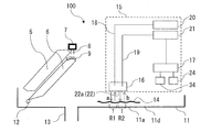
- FIG. 1 is a schematic diagram showing a cross section of an air conditioner 100 according to Embodiment 1 of the present invention.
- the white arrows indicate the direction of the air flow.
- the air conditioner 100 includes a fan 4, a heat exchanger 5, a humidifying material 6, a drain pan 11, and a supply unit 7 for supplying humidifying water inside the housing 1. , A cooling function, a heating function, and a humidifying function.
- a suction port 2 opening to the lower surface is formed, and on the other side surface of the housing 1, an air outlet 10 is formed.
- the air conditioner 100 when the fan 4 is driven, the air is sucked in from the suction port 2, and the conditioned air that has passed through the heat exchanger 5 is blown out from the blowout port 10.
- a filter 3 for removing dust from the air sucked into the housing 1 is disposed above the suction port 2.
- a fan 4 is arranged downstream of the filter 3, and air sucked upward from the suction port 2 by the fan 4 passes through the filter 3 and is blown into the housing 1.
- the heat exchanger 5 is located on the downstream side of the fan 4, and is arranged so as to be inclined such that the upstream side of the heat exchanger 5 is the lower end and the downstream side is the upper end.
- the heat exchanger 5 has, for example, a fin-and-tube structure made of aluminum, and heats or cools the air by exchanging heat between the air passing therethrough and the refrigerant flowing therethrough.
- the humidifying material 6 is formed, for example, by arranging a plurality of plate members in parallel, is arranged below the heat exchanger 5 along the inclination of the heat exchanger 5, and has a shape deformed by shearing.
- the humidifying material 6 has a long side substantially equal in length to the heat exchanger 5.
- the upper end of the humidifying material 6 has a mountain-shaped upper surface, and the diffusion material 9 is placed on the mountain-shaped upper surface.
- a supply unit 7 and a nozzle 8 for supplying water to the humidifier 6 are arranged, and the diffusion unit arranged on the upper surface of the humidifier 6 from the supply unit 7 and the nozzle 8 Water is supplied to the humidifying material 6 via the material 9.
- the water either tap water or industrial water can be used, but it is desirable that the amount of scale components, such as calcium, magnesium, and silica, which cause sediment is small.
- the drain pan 11 receives the water droplets 12 drained from the heat exchanger 5 or the humidifier 6.
- the drain pan 11 is arranged below the heat exchanger 5 and the humidifier 6 to receive the water droplets 12 drained from the heat exchanger 5 or the humidifier 6.
- the drain pan 11 accumulates, as drain water, water droplets 12 naturally flowing down from the heat exchanger 5 and the humidifier 6 by gravity.
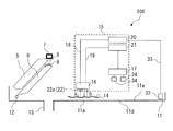
- FIG. 2 is a schematic diagram showing a cross section around the drain pan 11 of the air conditioner 100 according to Embodiment 1. As shown in FIG. 2, a drain pipe 13 is connected to a lower surface of the drain pan 11, and a detection unit 15 is disposed above the drain pan 11.
- the drain pipe 13 discharges drain water collected in the drain pan 11 to the outside. If the amount of water droplets 12 supplied from the heat exchanger 5 or the humidifying material 6 to the drain pan 11 is smaller than the amount of drain water discharged from the drain pipe 13, the drain water does not accumulate in the drain pan 11. When the amount of water droplets 12 supplied from the heat exchanger 5 or the humidifying material 6 to the drain pan 11 is larger than the amount of drain water discharged from the drain pipe 13, the level of the drain water accumulated in the drain pan 11 rises.
- the drain pipe 13 is an example of a discharge unit.
- the detection unit 15 has an ultrasonic sensor 16 that transmits and receives ultrasonic waves, and detects a contaminant 14 generated in the drain pan 11 by analyzing a response signal of the ultrasonic sensor 16.
- a specific example of the contaminant 14 here is a biofilm. That is, the detecting unit 15 detects the contaminant 14 generated on the upper surface of the drain pan 11.
- the detection unit 15 includes an electric wire 18, an electric wire 19, a power supply 20, an amplifier detection circuit 21, an ultrasonic sensor 16, an arithmetic unit 17, a storage unit 24, and a timekeeping unit 34.
- the ultrasonic sensor 16 of the detection unit 15 is disposed above a portion of the drain pan 11 where water easily accumulates. Examples of places where water easily accumulates in the drain pan 11 include the vicinity of a drain port connected to the drain pipe 13, the vicinity of the suction portion 30a of the drain pump 30 (see FIG. 11), and the vicinity of the humidifying material 6.
- the ultrasonic sensor 16 has a flat transmitting / receiving surface portion 22 that constitutes a transmitting surface and a receiving surface of an ultrasonic wave.
- the detection unit 15 is characterized in that the flat plane part 22a of the transmission / reception plane part 22 and the bottom plane part 11a constituting the bottom part 11d of the drain pan 11 are arranged in parallel.
- the detecting unit 15 generates a plurality of ultrasonic waves between the contaminant attached to the drain pan 11 and the flat portion 22a of the ultrasonic sensor 16 for one output wave of the ultrasonic wave transmitted from the ultrasonic sensor 16. It can be reflected over time.
- the bottom flat portion 11a of the bottom portion 11d of the drain pan 11 is arranged parallel to the horizontal plane.
- the distance between the bottom flat portion 11a of the drain pan 11 and the flat portion 22a of the transmission / reception face portion 22 depends on the size of the air conditioner 100, but the distance between the drain pan 11 and the ultrasonic sensor 16 is set to 10 to 200 mm. It is arranged open.
- the distance between the bottom flat portion 11a of the drain pan 11 and the flat portion 22a of the transmission / reception face portion 22 is preferably 10 to 150 mm, more preferably 10 to 100 mm, in order to obtain a plurality of reflected sounds of ultrasonic waves.
- the arithmetic unit 17 of the detection unit 15 analyzes the response signal of the ultrasonic sensor 16 and determines whether or not contaminants generated in the drain pan 11 exist.
- the arithmetic unit 17 of the detection unit 15 is configured by, for example, dedicated hardware or a CPU (Central Processing Unit) that executes a program stored in the storage unit 24.
- CPU Central Processing Unit
- the arithmetic unit 17 determines the presence or absence of the contaminant 14 by performing an arithmetic operation based on the data stored in the storage unit 24 and the voltage detected by the amplifier detection circuit 21.
- the storage unit 24 for example, a nonvolatile or volatile storage device such as a RAM, a ROM, a flash memory, an EPROM, and an EEPROM can be adopted.
- the storage unit 24 stores various data read by the arithmetic device 17 or stores the calculation result of the arithmetic device 17.
- the timer 34 includes, for example, a timer or a real-time clock, and measures the current time.
- the contaminant 14 is a composite of a sticky polysaccharide metabolized by bacteria or mold and a dirt component contained in the air, and is a contaminant of a viscous aggregate called a slime.
- the contaminants 14 are generated on the upper surface of the drain pan 11 by dropping water drops 12 containing floating bacteria or mold spores floating around the air conditioner 100 onto the drain pan 11. If the contaminants 14 adhere to and accumulate on the joint portion or wall surface between the drain pipe 13 and the drain pan 11, drain water cannot be discharged.
- bacteria or fungi harmful to the human body may propagate in the contaminants 14.
- An example of bacteria harmful to the human body is an aerobic Gram-negative bacterium called Legionella.
- Legionella a species of Legionella spp. And is described as Legionella @ pneumophila. Legionella is a resident bacterium in soil and the like. Legionella grows on the contaminant 14 and is released into the air, which poses a pathogenic risk.
- the contaminants 14 are not proliferated as much as possible, and it is recommended that the drain pan 11 be inspected and cleaned once a month, for example, as a regular inspection.
- the humidifying portion of the air conditioner 100 is often installed on the ceiling, and it is difficult to disassemble and clean the air conditioner 100.
- an antibacterial agent inside the drain pan 11, even when the growth of the contaminants 14 is prevented, the antibacterial agent disappears with time, and the effect is lost.
- the detection unit 15 determine whether or not the contaminant 14 is generated, and when the contaminant 14 is generated, it is desirable to warn of the necessity of cleaning the drain pan 11.
- the detection unit 15 transmits an ultrasonic wave in a direction of a solid arrow a perpendicular to the drain pan 11 and detects an ultrasonic wave reflected on the contaminant 14 in a direction of a dotted arrow b.
- the presence or absence of the contaminant 14 generated on the upper surface of the drain pan 11 is determined.
- R1 shown in FIG. 2 schematically shows the first reflection of the ultrasonic wave transmitted from the detection unit 15, and R2 schematically shows the second reflection of the ultrasonic wave. It is.
- the detecting unit 15 reflects the ultrasonic wave a plurality of times between the transmitting / receiving surface unit 22 of the ultrasonic sensor 16 and the contaminant 14 because the transmitting / receiving surface unit 22 of the ultrasonic sensor 16 and the drain pan 11 are arranged in parallel. There is a feature that can be made.
- the detection unit 15 detects a plurality of reflected sounds of the ultrasonic wave, and determines the presence or absence of the contaminant 14 by the arithmetic unit 17 from the first reflected sound, the second reflected sound,..., The n-th reflected sound. I do.
- FIG. 3 is a schematic diagram illustrating the ultrasonic sensor 16 of the detection unit 15 in FIG.
- the ultrasonic sensor 16 has a configuration in which a piezoelectric element 23, an electrode 25, an electrode 26, a lead wire 27, a lead wire 28, and a transmission / reception surface 22 that is an acoustic matching layer are accommodated in a housing 16a. Have been.
- the ultrasonic sensor 16 is configured by an integrated ultrasonic element that transmits and receives ultrasonic waves with one piezoelectric element 23.
- the transmission / reception surface part 22 has a flat part 22a formed in a flat shape. As shown in FIG.
- the transmission / reception surface portion 22 of the ultrasonic sensor 16 is arranged such that the flat portion 22 a and the flat bottom portion 11 a of the bottom 11 d of the drain pan 11 are parallel to each other.
- the electrode 25 is electrically connected to the piezoelectric element 23 via a lead wire 27 as shown in FIG.
- the electrode 26 is electrically connected to the piezoelectric element 23 via a lead wire 28. When a high-frequency voltage is applied between the electrode 25 and the electrode 26, the piezoelectric element 23 vibrates and generates ultrasonic waves.
- the detection unit 15 can use a transmission / reception integrated ultrasonic sensor 16, and thus can transmit ultrasonic waves by one piezoelectric element 23 and receive ultrasonic waves reflected from the contaminant 14. .
- the ultrasonic wave can be reflected between the transmitting / receiving surface portion 22 of the ultrasonic sensor 16 and the contaminant 14 a plurality of times, and the detecting unit 15 detects the reflected sound of the plurality of times. be able to.
- FIG. 4 is a schematic diagram illustrating another example of the ultrasonic sensor 16 of the detection unit 15 in FIG.
- the ultrasonic sensor 16 includes an ultrasonic transmission piezoelectric element 23 a, an electrode 25 a, an electrode 26 a, a lead wire 27 a, a lead wire 28 a, and a transmission / reception surface 22 which is an acoustic matching layer having the same casing. It is configured to be housed in the body 16b.
- the housing 16b accommodates a piezoelectric element 23b for ultrasonic reception, an electrode 25b, an electrode 26b, a lead wire 27b, and a lead wire 28b connected to the transmission / reception surface portion 22. It is configured.
- the ultrasonic sensor 16 may be configured by integrating a piezoelectric element 23a for transmitting ultrasonic waves and a piezoelectric element 23b for receiving ultrasonic waves.
- the transmission / reception surface portion 22 has a flat portion 22a formed in a flat shape. As shown in FIG. 2, the transmission / reception surface portion 22 is arranged such that the flat surface portion 22 a and the flat bottom surface portion 11 a of the bottom 11 d of the drain pan 11 are parallel to each other.
- the electrode 25a is electrically connected to the ultrasonic transmitting piezoelectric element 23a via the lead wire 27a.
- the electrode 26a is electrically connected to the ultrasonic transmitting piezoelectric element 23a via a lead wire 28a.
- the electrode 25b is electrically connected to the ultrasonic receiving piezoelectric element 23b via the lead wire 27b.
- the electrode 26b is electrically connected to the ultrasonic receiving piezoelectric element 23b via a lead wire 28b.
- the ultrasonic transmitting piezoelectric element 23a vibrates to generate ultrasonic waves. Further, as described above, when the generated ultrasonic wave is reflected from the drain pan 11 or the contaminant 14 on the drain pan 11 and reaches the piezoelectric element 23b for receiving the ultrasonic wave, and the ultrasonic element 23b generates a vibration derived from the ultrasonic wave. The voltage generated by the vibration is converted into an electric signal. This electrical signal is detected from the electrode 25b and the electrode 26b.
- the ultrasonic sensor 16 of the detection unit 15 can also use the piezoelectric element 23a for transmitting ultrasonic waves and the piezoelectric element 23b for receiving ultrasonic waves, which are joined to the same transmitting / receiving surface unit 22.
- the ultrasonic wave can be reflected a plurality of times between the transmitting / receiving surface portion 22 of the ultrasonic sensor 16 and the contaminant 14, and the detecting unit 15 has a configuration using one piezoelectric element 23.
- the reflected sound can be detected a plurality of times.
- the ultrasonic wave is transmitted by a pulse wave, and has a frequency of 40 kHz or more and 500 kHz or less.
- Ultrasound generally refers to sound waves having a frequency of 20 kHz or more.
- Ultrasonic waves have a characteristic that the higher the frequency of the ultrasonic waves, the better the resolution, but on the other hand, there is a trade-off relationship that the reach distance is short. Therefore, the frequency of the ultrasonic wave is desirably 100 to 400 kHz.
- the transmission method of the ultrasonic wave is not limited to the pulse wave, but may be a continuous wave.
- the pulse width may be arbitrarily set, but if it is too long, detection becomes difficult. Therefore, 1 to 5 times the wavelength is appropriate. As the number of pulses increases, the resolution tends to improve, but on the other hand, the effect of reverberation also increases, so that about 1 to 100 times is appropriate.
- the oscillation time of the ultrasonic wave is appropriately set in the range of 0.003 to 0.5 millisecond for the same reason.
- the ultrasonic wave transmitted from the ultrasonic sensor 16 is irradiated on the contaminant 14.
- Ultrasonic waves have the property of being reflected at the interface of an object.
- the contaminant 14 has a characteristic of having a porous shape.
- the ultrasonic wave transmitted by the ultrasonic sensor 16 propagates in the air in the direction of a solid arrow a perpendicular to the bottom flat surface 11 a of the drain pan 11 and reaches the interface of the contaminant 14. I do.
- the ultrasonic wave that has reached the interface of the contaminant 14 is partially reflected by the characteristics of the ultrasonic wave and the shape of the contaminant 14 and propagates toward the ultrasonic sensor 16 in the direction of the dotted arrow b. .
- the ultrasonic wave that has reached the ultrasonic sensor 16 is detected by the detection unit 15 as a first response.
- a part of the ultrasonic wave that has reached the ultrasonic sensor 16 is reflected by the plane portion 22 a of the transmission / reception surface portion 22, and flows again in the air in the direction of the solid arrow a perpendicular to the bottom plane portion 11 a of the drain pan 11.
- the ultrasonic wave reaching the interface of the contaminant 14 is partially reflected by the characteristics of the ultrasonic wave and the shape of the contaminant 14, and is directed toward the ultrasonic sensor 16 in the direction of the dotted arrow b. Propagate.
- the ultrasonic wave that has reached the ultrasonic sensor 16 is detected by the detection unit 15 as a second response.
- the last response of the ultrasonic wave that has reached the ultrasonic sensor 16 is the n-th response.
- the above-described phenomenon is repeated, and is repeated until the ultrasonic wave is attenuated and there is no response. Note that the other part of the ultrasonic wave that has reached the interface of the contaminant 14 is not reflected but passes through the interface of the contaminant 14.
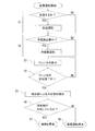
- FIG. 5 is a diagram showing an entire flow of operation by the air conditioner 100 according to Embodiment 1 of the present invention.
- the air conditioner 100 has the functions of a humidifying operation and a cooling / heating operation, and performs the air humidifying operation and the cooling / heating operation simultaneously or selectively according to the required outlet air temperature and humidity conditions.
- the air conditioner 100 determines whether or not to perform humidification in step S1, and determines whether or not the cooling and heating operation is necessary in step S2.
- step S3 the air conditioner 100 starts draining the drain water 29, and determines in step S4 whether the drain water 29 has been completely drained.
- step S5 the detection unit 15 detects the presence or absence of the contaminant 14, and in step S6, the detection unit 15 determines whether or not the contaminant 14 is present. I do. If the detection unit 15 determines in step S6 that the contaminant 14 is present, the process proceeds to step S7, and the detection unit 15 warns that the drain pan 11 is to be cleaned. On the other hand, when the detection unit 15 determines that the contaminant 14 does not exist in Step S6, the process proceeds to Step S8, and the operation of the air conditioner 100 is stopped assuming that the operation of the air conditioner 100 is completed.
- Step S8 the detection unit 15 determines that the contaminant 14 does not exist.
- step S1 of FIG. 5 when it is determined that humidification is performed and the humidification operation is started, the water stored in the supply unit 7 is transported as humidification water to the nozzle 8 above the diffusion material 9.
- the humidification water conveyed to the nozzle 8 is dropped from the tip of the nozzle 8 toward the upper part of the diffusion material 9, and the water is supplied to the humidification material 6.
- the humidifying water is uniformly diffused throughout the humidifying material 6 by utilizing the capillary force and gravity of the diffusing material 9, and a certain amount of the humidifying water is held by the humidifying material 6.
- the fan 4 starts operating.
- the air sucked from the suction port 2 by the operation of the fan 4 passes through the humidifying material 6 via the filter 3, the fan 4, and the heat exchanger 5, and goes out of the air conditioner 100 with the humidifying device, that is, indoors. Conveyed.
- the humidifying water held by the humidifying material 6 evaporates in contact with the air, humidifies the air, and is transported together with the air to the room.
- Excess humidification water of the humidifying material 6 that has not evaporated and is not used for humidification gathers near the lower end of the humidifying material 6 due to gravity, leaks out from the lower end of the humidifying material 6, and drops downward.
- the water droplets 12 leaked from the humidifier 6 and dropped are received by the drain pan 11 as drain water. Then, the drain water received by the drain pan 11 is discharged from the drain pipe 13.
- the humidifying operation of the air conditioner 100 the humidified air is supplied to the space to be humidified.
- Step S2 of FIG. 5 when it is determined that the cooling / heating operation is necessary and the cooling / heating operation is started, the surface of the heat exchanger 5 is heated or cooled by the flow of the heated or cooled refrigerant into the heat exchanger 5. . Specifically, during the heating operation, the heated refrigerant flows into the heat exchanger 5, the surface of the heat exchanger 5 is heated, and the air passing through the surface of the heat exchanger 5 is heated. During the cooling operation, the cooled refrigerant flows into the heat exchanger 5, the surface of the heat exchanger 5 is cooled, and the air passing through the surface of the heat exchanger 5 is cooled.
- the water vapor contained in the air becomes dew on the surface of the heat exchanger 5.
- the condensed water flows down from the heat exchanger 5, flows as a water droplet 12 to the drain pan 11, and is received by the drain pan 11 as drain water. Then, the drain water received by the drain pan 11 is discharged through the drain pipe 13 as in the case of the humidifying operation.
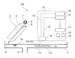
- FIG. 6 is a schematic diagram showing a cross section around the drain pan 11 during the humidification operation or the cooling operation of the air conditioner 100 according to Embodiment 1 of the present invention.
- the water droplets 12 received by the drain pan 11 are stored in the drain pan 11 as drain water 29.
- the drain water 29 is discharged from the drain pan 11 by the drain pipe 13 provided in the drain pan 11 (Step S3).
- the humidifying operation or the cooling operation of the air conditioner 100 is stopped, the supply of the water droplets 12 to the drain pan 11 is stopped, and after a certain period of time, the discharge of the drain water 29 by the drain pipe 13 is completed.
- the detection unit 15 causes the drain pan 11 to discharge water when a set time has elapsed after the cooling operation or the humidification operation of the air conditioner 100 has been stopped. Is completed, and the detection of the contaminant 14 is started. For example, when the set time is set to 20 minutes, the detection unit 15 determines that the drainage process has been completed in 20 minutes after the humidification operation or the cooling operation of the air conditioner 100 has been stopped, and that the drainage process has been completed. Start detection.
- the drainage speed varies depending on the size of the drain pipe 13 or the inclination of the drain pan 11, so that the time when drainage of the drain water 29 is completed varies depending on the drainage characteristics.
- the elapsed time from the stop of the humidifying operation or the cooling operation of the air conditioner 100 to the time when the water content becomes sufficiently steady is determined in advance, and the determined elapsed time is set to a set time (for example, 1). ⁇ 2 hours).
- the drain pan 11 when the drain pan 11 is made of plastic, the drain pan 11 generally has water repellency, and when the water level of the drain water 29 becomes low, the drain water 29 becomes a water droplet on the drain pan. From this, it may be considered that drainage of the drain water 29 is completed when the drain water 29 is present only partially in the bottom flat surface 11a of the bottom 11d of the drain pan 11 and water drops are discretely present.
- an elapsed time until a water droplet having a diameter of 20 mm or less is present on the bottom flat portion 11a of the bottom 11d of the drain pan 11 is determined in advance, and the determined elapsed time may be defined as a set time. Good.
- the set time is stored in the storage unit 24, and the arithmetic unit 17 of the detection unit 15 performs cooling based on the set time stored in the storage unit 24 and the time obtained from the clock unit 34. After the operation or the humidification operation is stopped, it is determined whether a set time has elapsed.
- the air conditioner 100 includes a water detection sensor, which is commercially available as a water leakage detector and detects a change in resistance between electrodes, on the upper surface of the drain pan 11. Arrange a plurality. Then, the detection unit 15 may regard the point at which the output of each water detection sensor decreases or the variation increases, assuming that the drainage process of the drain water 29 has been completed. Alternatively, assuming that the drain water 29 is drained and does not remain in the drain pan 11, the detection unit 15 may regard a state immediately before starting the humidifying operation or the cooling operation of the air conditioner 100 as a state in which the drain step is completed.
- a water detection sensor which is commercially available as a water leakage detector and detects a change in resistance between electrodes, on the upper surface of the drain pan 11. Arrange a plurality. Then, the detection unit 15 may regard the point at which the output of each water detection sensor decreases or the variation increases, assuming that the drainage process of the drain water 29 has been completed. Alternatively, assuming that the drain water 29 is
- Step S5 The detection of the contaminant 14 by the detection unit 15 (step S5) is performed in a state where the drain water 29 is drained from the drain pan 11 after the humidification operation or the cooling operation of the air conditioner 100 is stopped.
- the state in which the drain water 29 is drained is a state after the above-described draining step or immediately before the humidifying operation or the cooling operation of the air conditioner 100 is started.
- a set period of time for example, 1 to 2 hours
- the piezoelectric element 23 inside the ultrasonic sensor 16 vibrates, and the ultrasonic sensor 16 transmits an ultrasonic pulse wave having a wavelength of 300 kHz from the transmission / reception surface unit 22.
- the ultrasonic wave propagates in the air in the direction of the solid arrow a perpendicular to the bottom flat surface 11 a of the drain pan 11, and is reflected at the interface between the contaminant 14 and the air.
- the reflected ultrasonic wave propagates in the air in the direction of the dotted arrow b toward the transmitting / receiving surface portion 22 of the ultrasonic sensor 16.
- the detection unit 15 obtains the first vibration in the piezoelectric element 23 of the ultrasonic sensor 16. Then, a part of the ultrasonic wave that has reached the ultrasonic sensor 16 is reflected by the transmission / reception surface portion 22 and propagates again in the air in the direction of the solid arrow a perpendicular to the bottom flat surface portion 11a of the drain pan 11, thereby causing contamination. It is reflected again at the interface between the object 14 and the air. The reflected ultrasonic wave propagates in the air in the direction of the dotted arrow b toward the transmitting / receiving surface portion 22 of the ultrasonic sensor 16.
- the detecting unit 15 obtains a second vibration in the piezoelectric element 23 of the ultrasonic sensor 16.
- the detection unit 15 repeats the above-described phenomenon, and obtains the n-th vibration in the piezoelectric element 23 at which the reflection of the ultrasonic wave is stopped.
- the piezoelectric element 23 vibrates, a voltage is generated between the electrode 25 and the electrode 26, and the amplifier detection circuit 21 detects the first to n-th voltages as a response from the contaminant 14.
- the detection unit 15 determines the presence or absence of the contaminant 14 by performing an arithmetic operation with the arithmetic unit 17 based on the voltage detected by the amplifier detection circuit 21 (Step S6).
- the detection unit 15 determines that the contaminant 14 exists based on the determination result of the presence or absence of the contaminant 14, the detection unit 15 warns the drain pan 11 to be cleaned (step S7). Thereby, the user can know whether or not the contaminant 14 exists on the drain pan 11.
- the drain pan 11 is made of plastic such as ABS, has a higher acoustic impedance than air, and has a high smoothness, and therefore has a high ultrasonic reflectivity.
- the contaminant 14 has large irregularities, and the ultrasonic wave reaching the contaminant 14 has a property of being easily scattered. Therefore, in a state where neither the contaminant 14 nor the drain water 29 exists on the drain pan 11, the response of the ultrasonic wave is measured, and the degree of the ultrasonic wave scattering is measured based on the ultrasonic response. 14 can be quantified.
- FIG. 7 is a graph showing an ultrasonic response when the drain pan 11 shown in FIG. 2 is clean.
- FIG. 7 shows a response of the ultrasonic wave detected by the detection unit 15 in the drain pan 11 in a state where the contaminant 14 does not exist.
- the vertical axis of the graph indicates the response intensity of the ultrasonic wave in voltage P [mV]
- the horizontal axis of the graph indicates the time t [msec] after the irradiation of the ultrasonic wave.
- the change of the voltage until the elapsed time t 0 is derived from the resonance phenomenon of the detection unit 15.
- T 1, t 2 shown in FIG. 7, ⁇ ⁇ ⁇ , t 5 represent the time when the voltage reaches the peak value.
- P 1 , P 2 ,..., P 5 shown in FIG. 7 are peak voltages.
- the first peak value is obtained by receiving, as a response, the ultrasonic wave transmitted through the air and reflected at the interface between the air and the drain pan 11 by the piezoelectric element 23. That is, the peak value received by the piezoelectric element 23 is a response by the drain pan 11.
- the second peak value is such that a part of the first reflected sound is reflected on the transmitting / receiving surface part 22, propagates in the air again, and the second reflected ultrasonic wave at the interface between the air and the drain pan 11 is a piezoelectric element. 23 as a response.
- the voltage peak value of the response of the ultrasonic wave decreases each time the reflection is repeated, and the peak voltage becomes P 1 > P 2 > P 3 > P 4 > P 5 . This is considered to be because the ultrasonic wave was attenuated when propagating in the air as a medium, when reflected at the interface between the air and the drain pan 11, and when reflected at the interface between the air and the transmission / reception surface portion 22.
- FIG. 8 is a graph showing an ultrasonic response in the drain pan 11 on which the contaminants 14 shown in FIG. 2 are formed.
- the contaminants 14 used in the experiment in the graph of FIG. 8 were obtained by repeating the cycle of operating the humidifying operation of the air conditioner 100 for 6 hours continuously and then stopping the operation for 18 hours for 60 days, thereby obtaining the bottom flat portion of the drain pan 11. 11a.
- FIG. 8 shows a response of the ultrasonic wave detected by the detection unit 15 in the drain pan 11 in the state of FIG. 2 from which the drain water 29 is discharged.
- FIG. 8 shows a response of the ultrasonic wave detected by the detection unit 15 in the drain pan 11 in the state of FIG. 2 from which the drain water 29 is discharged.
- the vertical axis of the graph indicates the response intensity of the ultrasonic wave in voltage P [mV]
- the horizontal axis of the graph indicates the time t [msec] after the irradiation of the ultrasonic wave.
- the change of the voltage until the elapsed time t 0 ′ is derived from the resonance phenomenon of the detection unit 15.
- T 1 ′, t 2 ′, and t 3 ′ shown in FIG. 8 represent times when the voltage reaches a peak value.
- P 1 ′, P 2 ′, and P 3 ′ shown in FIG. 8 are peak voltages.
- This first peak value is a result of the ultrasonic wave propagating in the air and reflected at the interface between the air and the contaminant 14 being received by the piezoelectric element 23 as a response. That is, the peak value received by the piezoelectric element 23 is a response due to the contaminant 14.
- the voltage peak value of the response of the ultrasonic wave decreases each time the reflection is repeated, and the peak voltage becomes P 1 ′> P 2 ′> P 3 ′.
- the detecting unit 15 determines whether or not the contaminant 14 exists in Step S6.
- the following features are derived from the graphs of FIGS. 7 and 8 as a premise for the determination by the detection unit 15.
- the ultrasonic response after t 4 and t 5 shown in the ultrasonic response to the drain pan 11 without the contaminant 14 in FIG. 7 is seen in the ultrasonic response to the drain pan 11 in which the contaminant 14 is present in FIG. I could't.
- the peak value of the ultrasonic response voltage for the drain pan 11 having no contaminant 14 in FIG. 7 and the peak value of the ultrasonic response voltage for the drain pan 11 having the contaminant 14 in FIG. 8 are P 1 > P.
- the peak value of the voltage due to the ultrasonic wave response is smaller than the peak value of the voltage due to the ultrasonic wave response to the drain pan 11 where the contaminant 14 is present.
- the peak value was larger. It is considered that this is because there was a difference in the attenuation of the ultrasonic wave between the time when the ultrasonic wave reflected at the interface between the air and the drain pan 11 and the time when the ultrasonic wave reflected at the interface between the air and the contaminant 14. That is, it is considered that the contaminant 14 has a greater attenuation of the ultrasonic wave than the drain pan 11.
- t 1 It was almost the same time as ⁇ t 1 ′, t 2 ⁇ t 2 ′, and t 3 ⁇ t 3 ′. This is because the thickness of the contaminant 14 was less than 1 mm, and the ultrasonic wave propagation distance was almost equal between the case where the drain pan 11 without the contaminant 14 was used and the case where the drain pan 11 where the contaminant 14 was present was used. it is conceivable that.
- the ultrasonic wave propagation distance between the case where the drain pan 11 having no contaminant 14 is used and the case where the drain pan 11 where the contaminant 14 exists is different. Come. Therefore, when the thickness of the contaminant 14 is sufficiently thicker than 1 mm, the difference in ultrasonic response time between the case where the contaminant 14 does not exist in the drain pan 11 and the case where the contaminant 14 exists in the drain pan 11 is larger. It is thought to grow.
- the shape of the ultrasonic response voltage (also referred to as a waveform) was such that the peak top was large and the half width was small with the drain pan 11 alone, whereas the peak top was only the drain pan 11 when the contaminant 14 was present in the drain pan 11.
- the half width was smaller than in the case. Note that the half width indicates a width of time when the voltage becomes half of the peak value.
- the detecting unit 15 transmits an ultrasonic wave from the ultrasonic sensor 16 in a state where the drain water 29 is discharged, receives the ultrasonic wave reflected by the piezoelectric element 23, and detects the ultrasonic wave as a response.
- the presence or absence of the contaminant 14 is determined based on the voltage value.
- the detection unit 15 warns of the cleaning of the drain pan 11 (Step S7).
- the user can know whether or not the contaminant 14 exists on the drain pan 11.
- FIG. 9 shows a flowchart of the operation in determining whether or not the contaminant 14 in FIG. 5 exists.
- the determination of the presence or absence of the contaminant 14 is performed by the arithmetic unit 17 of the detection unit 15.
- the detection unit 15 starts determining whether or not the contaminant 14 exists (step ST1).
- the detection unit 15 determines whether or not the drain pan 11 is in an initial state (step ST2).
- the initial state of the drain pan 11 refers to a state in which the contaminants 14 are not formed in the drain pan 11 and the drain pan 11 is clean.
- the air conditioner 100 is started, and the air conditioner 100 is operated in a humidifying operation.
- the detection unit 15 records a record of the operation of the humidification operation or the cooling operation in the storage unit 24. Then, the arithmetic unit 17 of the detection unit 15 determines whether or not the drain pan 11 is in the initial state with reference to the presence or absence of the operation related to the humidification operation or the cooling operation of the storage unit 24.
- the definition of the initial state of the drain pan 11 is determined by the operator, and may be, for example, not after the air conditioner 100 is started for the first time, but after the air conditioner 100 is started a plurality of times. Alternatively, regardless of whether the air conditioner 100 has performed the humidifying operation or the cooling operation, the time when the air conditioner 100 is first activated may be defined as the initial state of the drain pan 11 in the detection unit 15.
- step ST2 when step ST2 is YES, that is, when the drain pan 11 is in the initial state, the detection unit 15 detects a signal of the drain pan 11 based on the reflected sound of the ultrasonic wave transmitted from the ultrasonic sensor 16 (step ST3).
- the voltage value detected by the amplifier detection circuit 21 fluctuates in plus and minus, and the ultrasonic intensity cannot be calculated as it is. Therefore, the arithmetic unit 17 calculates the square value of the voltage value detected by the amplifier detection circuit 21.
- the arithmetic unit 17 integrates the voltage square value in the range of the section T1, and obtains the ultrasonic intensity I 0 [(mV) 2 which is a product of the voltage square value P 2 [(mV) 2 ] and the time t [ms]. ⁇ ms] (step ST4).
- the section T1 is a section after the first reflection signal is received.
- the reception start time of the reflected signal is determined by the distance (d) between the ultrasonic sensor 16 and the bottom 11d of the drain pan 11.
- the value obtained by dividing the distance (2 ⁇ d) in which the ultrasonic wave reciprocates once by the speed of sound is defined as the beginning of the section T1.
- a value obtained by dividing a distance (2 ⁇ d) in which the ultrasonic wave reciprocates once by a sound velocity and an appropriate coefficient (safety factor), for example, 0.8 to 1.2, is set as the beginning of the section T1.
- the coefficient (safety factor) may be set in advance by analyzing a detection section of a received signal in a clean state.
- a value obtained by dividing the distance (10 ⁇ 2 ⁇ d) in which the ultrasonic waves reciprocate 10 times by the speed of sound (time in which the ultrasonic waves reciprocate 10 times) is obtained.
- a value obtained by adding twice the value is used.
- a value obtained by dividing the distance (10 ⁇ 2 ⁇ d) where the ultrasonic waves reciprocate 10 times by the speed of sound (time during which the ultrasonic waves reciprocate 10 times) is obtained, and the ultrasonic wave application is performed on this value.
- the value obtained by adding the value obtained by doubling the time is multiplied by an appropriate coefficient (safety factor), for example, 0.8 to 1.2.
- safety factor for example, 0.8 to 1.2.
- this magnification is not limited to “2 times” and is determined in consideration of reverberation.
- the end of the section T1 may be arbitrarily set depending on the accuracy of the detector and the accuracy of the arithmetic unit 17.
- the arithmetic unit 17 uses the value of the ultrasonic intensity I 0 [(mV) 2 ⁇ ms] for the drain pan 11 in a state where the contaminant 14 does not exist as a value in the initial state of the drain pan 11 where the contaminant 14 does not exist. It is stored in the storage unit 24 (step ST5).
- the arithmetic unit 17 stores the value of the ultrasonic intensity I 0 [(mV) 2 ⁇ ms] in the storage unit 24 as the value of the initial state of the drain pan 11, the determination of the presence or absence of the contaminant 14 ends (step ST6).
- the ultrasonic intensity I 0 [(mV) 2 ⁇ ms] in the initial state of the drain pan 11 may be stored in the storage unit 24 in advance as a specific value based on the characteristics of the drain pan 11. In this case, when the operation of the device of the air conditioner 100 is started, the determination of whether or not the drain pan 11 is in the initial state in step ST2 is omitted. Then, the detection unit 15 performs the flow after step ST7 using the ultrasonic intensity I 0 [(mV) 2 ⁇ ms] stored in the storage unit 24.
- step ST7 when step ST2 is NO, that is, when the drain pan 11 is not in the initial state, the determination of the presence or absence of the contaminant 14 by the detection unit 15 is in a standby state until step S5 in FIG. 5 (step ST7).
- the detecting unit 15 detects a signal of the contaminant 14 based on the reflected sound of the ultrasonic wave transmitted from the ultrasonic sensor 16 (step ST8).
- the arithmetic unit 17 of the detection unit 15 performs the same calculation as the ultrasonic intensity I 0 based on the voltage value detected by the amplifier detection circuit 21 to perform the ultrasonic intensity I 0.
- step ST9 [(mV) 2 ⁇ ms] is obtained (step ST9). Further, the arithmetic unit 17 of the detection unit 15 reads out the value of the ultrasonic intensity I 0 ′ from the storage unit 24. (Step ST10). Then, the arithmetic unit 17 of the detecting unit 15 determines whether or not the ratio between the ultrasonic intensity I 0 and the ultrasonic intensity I 0 ′ exceeds a threshold (step ST11).
- the detection unit 15 receives the reflected sound of the ultrasonic wave a plurality of times as a signal, and determines the presence or absence of a contaminant based on a value obtained by integrating the received signal over a set time including a response section of the reflected sound over a plurality of times. to decide.
- the arithmetic unit 17 of the detection unit 15 determines that the ratio between the ultrasonic intensity I 0 and the ultrasonic intensity I 0 ′ exceeds the threshold, it determines that the contaminant 14 is present in the drain pan 11. (Step ST12).
- the arithmetic unit 17 of the detection unit 15 determines that the contaminant 14 is present in the drain pan 11, the determination of the presence or absence of the contaminant 14 ends (step ST13).
- the arithmetic unit 17 of the detection unit 15 determines that the ratio between the ultrasonic intensity I 0 and the ultrasonic intensity I 0 ′ is equal to or less than the threshold, the arithmetic unit 17 determines that the contaminant 14 is not present in the drain pan 11. (Step ST14).
- the arithmetic unit 17 of the detection unit 15 determines that the contaminant 14 is not present in the drain pan 11, the determination of the presence or absence of the contaminant 14 ends (step ST15).
- the improvement of the determination accuracy in the method of determining whether or not the contaminant 14 is present by the arithmetic unit 17 is considered as follows.
- the ratio between the ultrasonic intensity I 0 and the ultrasonic intensity I 0 ′ is about 10% to 30% larger than that of the case.
- the amplifier detection circuit 21 of the detection unit 15 detects the response voltage of the ultrasonic wave after the above-described drainage process and immediately before the humidification operation after the drainage process or immediately before the cooling operation after the drainage process. Do.
- the detection unit 15 determines whether or not the contaminant 14 exists, the accuracy of the determination as to whether or not the contaminant 14 exists further improves.
- the threshold value of the ultrasonic intensity I 0 / ultrasonic intensity I 0 ′ for determining the presence or absence of the contaminant 14 may be set, for example, between 2 and 3.
- the value of the ultrasonic intensity I 0 / ultrasonic intensity I 0 ′ in the presence or absence of the contaminant 14 is previously confirmed, and the presence or absence of the contaminant 14 is determined. It is preferable to determine a threshold value of the ultrasonic intensity I 0 / the ultrasonic intensity I 0 ′ to be determined.
- the arithmetic unit 17 uses the section T1 for the time t [ms] when calculating the ratio between the ultrasonic intensity I 0 and the ultrasonic intensity I 0 ′.
- the arithmetic unit 17 can use the section T2 for the time t [ms], and more preferably the section T4.
- the section T1, the section T2, the section T3, the section T4,..., And the section Tn are sections after the first reflection signal, the second reflection signal,.
- the reception start time of the reflected signal is determined by the distance (d) between the ultrasonic sensor 16 and the bottom 11d of the drain pan 11.
- a value obtained by dividing the distance (2 ⁇ 2 ⁇ d) in which the ultrasonic wave reciprocates twice by the speed of sound is defined as the beginning of the section T2 or the like.
- the coefficient (safety factor) may be set in advance by analyzing a detection section of a received signal in a clean state.
- a value obtained by dividing a distance (10 ⁇ 2 ⁇ d) in which the ultrasonic waves reciprocate 10 times by the speed of sound (time during which the ultrasonic waves reciprocate 10 times) is obtained.
- a value obtained by adding a value obtained by multiplying by two is obtained.
- a value obtained by dividing the distance (10 ⁇ 2 ⁇ d) in which the ultrasonic waves reciprocate 10 times by the speed of sound (time during which the ultrasonic waves reciprocate 10 times) is obtained.
- a value obtained by multiplying a value obtained by doubling the application time by a suitable coefficient (safety factor), for example, 0.8 to 1.2 is set.
- the above “10 reciprocations” is an example, and the number of reciprocations of the ultrasonic wave may be arbitrarily set.
- “a value obtained by doubling the ultrasonic wave application time” is added.
- this magnification is not limited to “2 times” and is determined in consideration of reverberation.
- the end of the section T1, the section T2, the section T3, the section T4,..., The section Tn may be arbitrarily set according to the accuracy of the detector and the accuracy of the arithmetic unit 17.
- the arithmetic device 17 calculates the response of the second and subsequent multiple reflection responses, whereby the response of the ultrasonic wave that has undergone the attenuation of the ultrasonic wave occurring at the interface between the air and the contaminant 14 a plurality of times can be analyzed. Therefore, the difference in ultrasonic response between the initial state of the drain pan 11 where the contaminant 14 does not exist and the state of the drain pan 11 where the contaminant 14 exists becomes larger, and the detection accuracy of the contaminant 14 improves.
- the arithmetic unit 17 calculates the ratio between the ultrasonic intensity I 0 and the ultrasonic intensity I 0 ′
- a case was also used in which the response voltage in the section T2 was used for the time t [ms].
- the ultrasonic intensity I 0 / ultrasonic intensity I 0 ′ is higher than when the calculation is performed using only the response voltage of the first reflected sound. In some cases, the value of was increased 3.3 times.
- the contaminant 14 can be easily detected by calculating the signal based on the second and subsequent reflected sounds. become.
- the voltage square value is integrated in a section corresponding to a half width of each peak voltage value, and the voltage square in each section is calculated.
- the ultrasonic intensity I [(mV) 2 ⁇ ms] which is a product of the values may be calculated.
- the arithmetic unit 17 of the detector 15 the ultrasonic intensity I 0 in the initial state of the drain pan 11 which contaminants 14 not present, and comparing the ultrasonic intensity I 0 'of the drain pan 11 that the presence or absence of contaminants 14 are not sure .
- the arithmetic unit 17 of the detection unit 15 determines that the contaminant 14 is formed when the ratio between the ultrasonic intensity I 0 and the ultrasonic intensity I 0 ′ exceeds the threshold. That is, the detection unit 15 receives the reflected sound of the ultrasonic wave a plurality of times as a signal, and determines whether or not there is a contaminant based on a value obtained by integrating the signal value with time in a half width range from each peak value of the received signal. Judge. At this time, when judging the presence or absence of the contaminant 14, whether the product of the voltage square values of each reflection is compared or the voltage square value of a plurality of reflections is compared, the sum of all is compared. May be. In this case, the ultrasonic intensity I 0 / ultrasonic intensity I 0 ′ may be about 10 to 30% higher than when the calculation is performed using only the first reflected sound, and whether or not the contaminant 14 exists. The accuracy of the determination is improved.
- the arithmetic unit 17 may determine the presence or absence of the contaminant 14 using the voltage P [mV] of the peak value of the ultrasonic response. That is, the detection unit 15 receives the reflected sound of the ultrasonic wave a plurality of times as a signal, and determines the presence or absence of the contaminant based on each peak value of the received signal. For example, the arithmetic unit 17 calculates the sum of the voltage P [mV] of each peak value of the ultrasonic wave in the drain pan 11 where the contaminant 14 does not exist and the peak value of the ultrasonic wave in the drain pan 11 where the presence or absence of the contaminant 14 is not known. Compare with the sum of the voltages P ′ [mV].
- the square of the voltage is used because the received signal is a voltage.
- the calculation may be performed according to the above-described example.
- the received signal is input as a voltage.
- the signal is not necessarily required to be a voltage, and may be converted into another digital signal and operated.
- the measurement of the ultrasonic wave was performed when the set time had elapsed from the end of the humidification operation or the cooling operation of the air conditioner 100 and the drainage process was completed. However, the measurement of the ultrasonic wave does not have to wait for the elapse of the set time from the end of the humidification operation or the cooling operation of the air conditioner 100 as long as the measurement can be performed without interference from the water surface of the drain water 29.
- a heater is installed near the ultrasonic sensor 16, and when the humidifying operation or the cooling operation of the air conditioner 100 is completed, the heater is heated to evaporate the drain water 29. Ultrasonic measurement may be performed.
- the air conditioner 100 is configured such that the bottom flat portion 11a forming the bottom portion 11d of the drain pan 11 and the flat portion 22a forming the receiving surface of the ultrasonic sensor 16 are arranged in parallel. Therefore, since the detection unit 15 identifies the presence or absence of the contaminant 14 based on the reflected sound of the ultrasonic wave from the contaminant 14 a plurality of times, the detection unit 15 detects the contaminated material 14 more than the identification based on the single reflected sound of the ultrasonic wave. The detection accuracy is improved. More specifically, in the air conditioner 100, when it is determined that the drain water 29 has been sufficiently discharged, that is, the draining process has been completed, the detection unit 15 causes the ultrasonic sensor 16 to transmit ultrasonic waves.
- the ultrasonic vibration is received by the piezoelectric element 23 and detected by the amplifier detection circuit 21 as a response having a plurality of peak voltages. If contaminants 14 are present, the transmitted ultrasound is attenuated by the contaminants 14. Therefore, the accuracy of detecting the presence or absence of the contaminant 14 is improved in the air conditioner 100 by calculating the ultrasonic intensity of the ultrasonic wave reflected by the detection unit 15 a plurality of times.
- the detecting unit 15 generates a plurality of ultrasonic waves between the contaminant attached to the drain pan 11 and the flat portion 22a of the ultrasonic sensor 16 for one output wave of the ultrasonic wave transmitted from the ultrasonic sensor 16. It is characterized by being reflected over time. Therefore, since the detection unit 15 identifies the presence or absence of the contaminant 14 based on the reflected sound of the ultrasonic wave from the contaminant 14 a plurality of times, the detection unit 15 detects the contaminated material 14 more than the identification based on the single reflected sound of the ultrasonic wave. The detection accuracy is improved.
- the detection unit 15 receives the reflected sound of the ultrasonic wave a plurality of times as a signal, and determines the presence or absence of a contaminant based on a value obtained by integrating the received signal at a set time including a response section of the reflected sound over a plurality of times. to decide.
- the detection unit 15 receives a plurality of reflected sounds of the ultrasonic wave as a signal, and determines whether or not a contaminant exists based on a value obtained by integrating the signal value with time in a half width range from each peak value of the received signal. Judge.
- the detection unit 15 receives a plurality of reflected sounds of the ultrasonic wave as a signal, and determines the presence or absence of a contaminant based on each peak value of the received signal. Alternatively, the detection unit 15 determines the presence or absence of the contaminant based on the signals received after the second time. In these cases, since the detection unit 15 identifies the presence or absence of the contaminant 14 based on the reflected sound of the ultrasonic wave from the contaminant 14 a plurality of times, the detection unit 15 performs the detection based on the reflected sound of the ultrasonic wave once. 14, the detection accuracy is improved. Further, since the noise of the signal can be excluded, the detection accuracy of the contaminant 14 is improved.
- the drain pan 11 and the ultrasonic sensor 16 are arranged at an interval such that the distance between the bottom flat portion 11a and the flat portion 22a is 10 to 200 mm.
- the air conditioner 100 obtains a plurality of reflected sounds of ultrasonic waves between the ultrasonic sensor 16 and the drain pan 11 or the contaminant 14 by arranging the drain pan 11 and the ultrasonic sensor 16 in this manner. Can be.
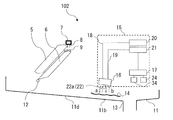
- FIG. 10 is a schematic diagram showing a cross section around the drain pan 11 of the air conditioner 102 according to Embodiment 2 of the present invention.
- the bottom flat portion 11b of the bottom 11d of the drain pan 11 has a region inclined with respect to the horizontal plane.
- a drain pipe 13 is arranged at the lower part.
- the air conditioner 102 according to Embodiment 2 is different from the air conditioner 102 in that the bottom flat portion 11b of the drain pan 11 is parallel to the horizontal surface in that the bottom flat portion 11b of the drain pan 11 has a region inclined with respect to the horizontal surface. It is different from the configured air conditioner 100 of the first embodiment.
- the other configuration of the air conditioner 102 according to Embodiment 2 is the same as that of the air conditioner 100 according to Embodiment 1, and thus the description is omitted.
- the air conditioner 102 according to Embodiment 2 includes: a detection unit 15 disposed above the drain pan 11; and a drain pan 11 having a bottom 11d that is equally inclined with the transmission / reception surface 22 of the ultrasonic sensor 16 of the detection unit 15.
- the air conditioner 102 according to Embodiment 2 includes a drain pan 11 having a bottom portion 11d inclined with respect to a horizontal plane, and a transmission / reception surface portion 22 that is arranged to be inclined equally to the inclined bottom portion 11d of the drain pan 11.
- the bottom flat portion 11b of the bottom 11d of the drain pan 11 and the flat portion 22a of the transmitting / receiving surface portion 22 are arranged in parallel.
- the drain water 29 is removed from the drain pan 11 due to the inclination of the drain pan 11, so that the air conditioner 102 according to the second embodiment is less than the air conditioner 100 according to the first embodiment.
- the amount of remaining water on the drain pan 11 becomes small.
- the detection unit 15 transmits the pulse wave of the ultrasonic wave by the ultrasonic sensor 16 in the direction of the solid line arrow a perpendicular to the drain pan 11, and repeats the response of the ultrasonic wave that reaches the contaminant 14 and is reflected a plurality of times. Detect over.
- the arithmetic unit 17 of the detection unit 15 detects the response of the ultrasonic wave, and determines that the contaminant 14 is formed when the ratio between the ultrasonic intensity I 0 and the ultrasonic intensity I 0 ′ exceeds the threshold, and determines that the drain pan is formed. Assuming that the contaminant 14 is present in the drain 11, the cleaning of the drain pan 11 is warned.
- the drain water on the drain pan 11 is more easily discharged from the air conditioner 100 according to the first embodiment by inclining the drain pan 11.
- the air conditioner 102 according to Embodiment 2 can detect the presence or absence of the contaminant 14 by ultrasonic waves without being affected by the surface of the drain water. Therefore, the air conditioner 102 according to Embodiment 2 can detect the presence or absence of the contaminant 14 more accurately than the air conditioner 100 according to Embodiment 1.
- the drain pan 11 has a region inclined with respect to the horizontal plane, and has a drain pipe 13 at the lowest part of the inclined drain pan 11. Therefore, the air conditioner 102 according to the second embodiment can discharge more drain water below the detection unit 15 than the air conditioner 100 according to the first embodiment. As a result, the air conditioner 102 according to Embodiment 2 can improve the detection accuracy of the contaminant 14 more than the air conditioner 100 according to Embodiment 1.
- FIG. 11 is a schematic diagram showing a cross section around the drain pan 11 of the air conditioner 104 according to Embodiment 3 of the present invention.
- the air conditioner 104 according to Embodiment 3 is different from the air conditioner 100 according to Embodiment 1 in that a drain pump 30 and a drain drain pipe 31 are provided.
- the air conditioner 104 according to the third embodiment is different from the air conditioner 100 according to the first embodiment, for example, when the air conditioner is disposed in a place where drainage of drain water by gravity via the drain pipe 13 is difficult.
- Used for The other configuration of the air conditioner 104 according to Embodiment 3 except for including the drain pump 30 and the drain drain pipe 31 is the same as that of the air conditioner 100 according to Embodiment 1, and thus the description is omitted.
- the air conditioner 104 includes a discharge unit 35 that discharges the water received by the drain pan 11.
- the discharge unit 35 is disposed above the drain pan 11 and includes a drain pump 30 that suctions water from the drain pan 11 from the suction unit 30a, and a drain drain pipe 31 that discharges the water drawn by the drain pump 30.
- the drain pump 30 is, for example, an electrically operated pump with a propeller, is disposed above the drain pan 11, and sucks up drain water on the drain pan 11 from the suction part 30a.
- the drain drain pipe 31 is connected to the drain pump 30, and discharges drain water sucked up by the drain pump 30 to the outside.
- the drain pump 30 and the drain drain pipe 31 are examples of the discharge unit 35.
- the drain water on the drain pan 11 is forcibly sucked up from the drain pan 11 by the power of the drain pump 30 and discharged to the outside by the drain drain pipe 31.
- the drain pan 11 is in a state of being drained by the operation of the drain pump 30, as shown in FIG.
- the detection unit 15 vibrates the piezoelectric element 23 inside the ultrasonic sensor 16 and transmits an ultrasonic pulse wave having a wavelength of 300 kHz.
- the ultrasonic wave propagates in the air in the direction of a solid arrow a perpendicular to the drain pan 11, and is reflected at the interface between the contaminant 14 and the air.
- the reflected ultrasonic wave propagates in the air in the direction of the dotted arrow b toward the transmission / reception surface portion 22 of the ultrasonic sensor 16, and the piezoelectric element 23 of the ultrasonic sensor 16 obtains the first vibration by the arrived ultrasonic wave. . Then, a part of the ultrasonic wave that has reached the ultrasonic sensor 16 is reflected by the transmission / reception surface portion 22 and propagates in the air in the direction of the solid arrow a perpendicular to the drain pan 11, and the interface between the contaminant 14 and the air Is reflected again at.
- the reflected ultrasonic wave propagates toward the transmission / reception surface 22 of the ultrasonic sensor 16 in the direction of the dotted arrow b, and the piezoelectric element 23 of the ultrasonic sensor 16 obtains a second vibration due to the ultrasonic wave that has arrived.
- the above-described phenomenon is repeated, and the piezoelectric element 23 of the ultrasonic sensor 16 obtains the vibration up to the n-th time when the reflection of the ultrasonic wave is stopped.
- n times of voltage generated between the electrode 25 and the electrode 26 are detected by the amplifier detection circuit 21.
- the arithmetic unit 17 performs an arithmetic operation based on the response detected by the amplifier detection circuit 21, and the arithmetic unit 17 determines whether or not the contaminant 14 exists.
- the arithmetic unit 17 determines that the contaminant 14 is present, a warning of cleaning the drain pan 11 is issued. Thereby, the user can know whether or not the contaminant 14 exists on the drain pan 11. As described above, the drain pan 11 can be drained even during the humidifying operation or the cooling operation of the air conditioner 104, and the presence or absence of the contaminant 14 can be detected.
- the drain pump 30 Even if the drain pump 30 operates, the drain water on the drain pan 11 is not immediately drained, and there is a time difference between the operation of the drain pump 30 and the drain water drain.
- the contaminants 14 are immersed in the drain water 29 and are in a submerged state.
- the water level decreases after a lapse of time, so that the pollutants 14 are exposed to the air.
- the drainage process based on the operation of the drain pump 30 detects the contaminant 14 after a certain period of time, that is, after a steady state, so that the influence of the drain water 29 on the ultrasonic measurement can be eliminated. Therefore, the drainage process based on the operation of the drain pump 30 is preferable for the operation of detecting the contaminant 14.
- the air conditioner 104 includes the drain pump 30 that is provided above the drain pan 11 and sucks up water, and the drain drain pipe 31 that discharges water. Therefore, even during the humidifying operation or the cooling / heating operation of the air conditioner 104, the contaminants 14 do not immerse in the drain water 29. As a result, the detection unit 15 can detect the presence or absence of the contaminant 14 without erroneously determining that the presence or absence of the contaminant 14 is a detection result based on the surface of the drain water 29.
- FIG. FIG. 12 is a schematic diagram showing a cross section around the drain pan 11 of the air conditioner 106 according to Embodiment 4 of the present invention.
- the air conditioner 106 according to the fourth embodiment is different from the air conditioners according to the first to third embodiments in that a water level sensor 32 is provided on the upper surface 11e of the bottom 11d of the drain pan 11, as shown in FIG. 100 mag.
- the other configuration is the same as that of the air conditioner 100 according to Embodiment 1 except that the water level sensor 32 is provided on the upper surface 11e of the bottom 11d of the drain pan 11. Therefore, the description is omitted.
- the air conditioner 106 includes the water level sensor 32 that detects the level of water received by the drain pan 11. When the water level detected by the water level sensor 32 is zero or an approximate value of zero, the detection unit 15 determines that the drain pan 11 has completed draining water, and starts detecting the contaminant 14.
- the water level sensor 32 is connected to the power supply 20 via the electric wire 33 and constantly monitors the water level of the drain water accumulated in the drain pan 11. When the water level sensor 32 detects that the water level has become equal to or less than a certain value close to zero, the detection unit 15 starts detecting the contaminant 14 assuming that drain water discharge has ended.
- a switch type device using a float can be used as the water level sensor 32.
- the ultrasonic wave propagates in the air in the direction of a solid arrow a perpendicular to the drain pan 11, and is reflected at the interface between the contaminant 14 and the air.
- the reflected ultrasonic wave propagates in the air in the direction of the dotted arrow b toward the transmission / reception surface portion 22 of the ultrasonic sensor 16, and the piezoelectric element 23 of the ultrasonic sensor 16 obtains the first vibration by the arrived ultrasonic wave. .
- a part of the ultrasonic wave that has reached the ultrasonic sensor 16 is reflected by the transmission / reception surface portion 22 and propagates in the air in the direction of the solid arrow a perpendicular to the drain pan 11, and the interface between the contaminant 14 and the air Is reflected again at.
- the reflected ultrasonic wave propagates toward the transmission / reception surface 22 of the ultrasonic sensor 16 in the direction of the dotted arrow b, and the piezoelectric element 23 of the ultrasonic sensor 16 obtains a second vibration due to the ultrasonic wave that has arrived.
- the piezoelectric element 23 of the ultrasonic sensor 16 obtains the vibration up to the n-th time when the reflection of the ultrasonic wave is stopped. Then, n times of voltage generated between the electrode 25 and the electrode 26 are detected by the amplifier detection circuit 21.
- the arithmetic unit 17 performs an arithmetic operation based on the response detected by the amplifier detection circuit 21, and the arithmetic unit 17 determines whether or not the contaminant 14 exists.
- a warning of cleaning the drain pan 11 is issued. Thereby, the user can know whether or not the contaminant 14 exists on the drain pan 11. As described above, the drain pan 11 can be drained even during the humidifying operation or the cooling operation of the air conditioner 106, and the presence or absence of the contaminant 14 can be detected.
- the water level sensor 32 has been described as an example of a switch type device using a float.
- the water level sensor 32 is not limited to the switch type device, and an ultrasonic reflection type device and an infrared reflection type device may be used.
- An apparatus of another system such as an apparatus may be used.
- the water level sensor 32 may be arranged anywhere as long as the upper surface 11e of the bottom 11d of the drain pan 11 is provided.
- the air conditioner 106 drains drain water through the drain pipe 13.
- the air conditioner 106 may have a configuration in which drain water is drained by the drain pump 30 and the drain drain pipe 31 disposed above the drain pan 11. Good.
- the water level sensor 32 is provided on the upper surface 11e of the drain pan 11.
- the detection unit 15 determines that the drain water has been discharged.
- the detection unit 15 starts the detection of the contaminant 14 based on the detection result of the water level sensor 32. Therefore, the detection unit 15 can perform the operation of detecting the contaminant 14 while eliminating the influence of the drain water as much as possible.
Landscapes
- Engineering & Computer Science (AREA)
- Chemical & Material Sciences (AREA)
- Physics & Mathematics (AREA)
- Mechanical Engineering (AREA)
- General Engineering & Computer Science (AREA)
- Combustion & Propulsion (AREA)
- Radar, Positioning & Navigation (AREA)
- Remote Sensing (AREA)
- General Physics & Mathematics (AREA)
- Life Sciences & Earth Sciences (AREA)
- Acoustics & Sound (AREA)
- Immunology (AREA)
- Health & Medical Sciences (AREA)
- Analytical Chemistry (AREA)
- Biochemistry (AREA)
- General Health & Medical Sciences (AREA)
- Computer Networks & Wireless Communication (AREA)
- Pathology (AREA)
- Biodiversity & Conservation Biology (AREA)
- Ecology (AREA)
- Environmental & Geological Engineering (AREA)
- Environmental Sciences (AREA)
- Air Conditioning Control Device (AREA)
- Devices For Blowing Cold Air, Devices For Blowing Warm Air, And Means For Preventing Water Condensation In Air Conditioning Units (AREA)
Abstract
空気調和機(100)は、水を受けるドレンパン(11)と、超音波の発信と受信を行う超音波センサ(16)を有し、超音波センサの応答信号を解析してドレンパンに生成された汚染物(14)を検出する検出部(15)と、を備え、ドレンパンの底部を構成する底部平面部(11a)と、超音波センサの受信面(22a)を構成する平面部とが平行に配置されているものである。
Description
本発明は、空気調和機に関し、特に、ドレンパンに生成される汚染物を検出する空気調和機に関するものである。
一般に、配管内部における海生物付着状況の測定方法として、検査管の外周の一点に超音波探傷器の探触子を当て、管本体からのエコーと海生物表面からのエコーとを計測し、海生物表面からのエコーの伝搬距離を読み取り、海生物の付着厚さを測定する測定方法が知られている(例えば、特許文献1参照)。また、ライニング部の非破壊検査方法のように、ライニング部材との接触面に対して垂直方向から超音波を発射し接触面からの反射波を受信し、密着度とともにライニング部材の厚さを測定できる検査方法が知られている(例えば、特許文献2参照)。
しかしながら、特許文献1及び特許文献2のいずれの方法においても、付着物の厚さ、密着度を測定するものであり、当該方法を空気調和機のドレンパン上に生成されたバイオフィルムなどの汚染物の検出に適用する動機は、これらの文献には開示も示唆もされてない。バイオフィルムとは、ドレンパン等に貯留した水に微生物が繁殖して発生した半固形状のヌメリである。バイオフィルムなどの汚染物の厚み、大きさ等の性状は様々である。バイオフィルムなどの汚染物は、ドレンポンプあるいはドレンホースを詰まらせるおそれがあり、バイオフィルムなどの汚染物の存在は衛生面でも好ましいものではない。また、ドレンパンは、排水受けとも呼ばれ、建築物衛生法で法定点検の対象であることから、定期的な清掃とメンテナンスを実施する必要がある。更に、ドレンパンは、空気調和機の内部でドレンポンプ等と一体として構成されており、清掃、メンテナンス等は、空気調和機を分解して行う必要がある。そのため、例えば、天井裏などに空気調和機が配置されていると、清掃、メンテナンス等に非常に手間とコストがかかってしまう。
しかしながら、特許文献1及び特許文献2の方法を用いて空気調和機のドレンパン上に生成された汚染物を検出すると、厚みが薄い汚染物、あるいは、大きさが小さい汚染物では反射音が清浄な(汚染物のない)ドレンパンと大差がなく、汚染物の検出が困難である場合がある。
本発明は、上記のような課題を解決するものであり、ドレンパン上に形成された汚染物の性状等による影響を受けても汚染物の存否を検出する精度を向上させることができる空気調和機を提供するものである。
本発明に係る空気調和機は、水を受けるドレンパンと、超音波の発信と受信を行う超音波センサを有し、超音波センサの応答信号を解析してドレンパンに生成された汚染物を検出する検出部と、を備え、ドレンパンの底部を構成する底部平面部と、超音波センサの受信面を構成する平面部とが平行に配置されているものである。
本発明に係る空気調和機は、ドレンパンの底部を構成する底部平面部と、超音波センサの受信面を構成する平面部とが平行に配置されているものである。そのため、検出部は、汚染物からの複数回の超音波の反射音に基づいて汚染物の存否を識別するため、1回の超音波の反射音に基づく識別よりも汚染物の検出精度が向上する。
以下、本発明の実施の形態に係る空気調和機100、空気調和機102、空気調和機104、空気調和機106等について図面等を参照しながら説明する。なお、図1を含む以下の図面では、各構成部材の大きさ、形状は、説明のために分かりやすく表しており、各構成部材の相対的な寸法の関係及び形状等が実際のものとは異なる場合がある。また、以下の図面において、同一の符号を付したものは、同一又はこれに相当するものであり、このことは明細書の全文において共通することとする。また、理解を容易にするために方向を表す用語(例えば「上」、「下」、「右」、「左」、「前」、「後」など)を適宜用いるが、それらの表記は、説明の便宜上、そのように記載しているだけであって、装置あるいは部品の配置及び向きを限定するものではない。
実施の形態1.
<空気調和機100の構成>
図1は、本発明の実施の形態1に係る空気調和機100の断面を示す概略模式図である。図1において、白抜き矢印は空気流の方向を示している。図1に示すように、空気調和機100は、筐体1の内部に、ファン4、熱交換器5、加湿材6、ドレンパン11、及び、加湿用の水を供給する供給部7を有し、冷房機能と、暖房機能と、加湿機能とを備えている。筐体1の一方の側面側には、下面に開口する吸込口2が形成されており、筐体1の他方の側面には、吹出口10が形成されている。空気調和機100は、ファン4が駆動することにより、吸込口2から空気が吸い込まれ、熱交換器5通過した調和空気を吹出口10から吹き出す。
<空気調和機100の構成>
図1は、本発明の実施の形態1に係る空気調和機100の断面を示す概略模式図である。図1において、白抜き矢印は空気流の方向を示している。図1に示すように、空気調和機100は、筐体1の内部に、ファン4、熱交換器5、加湿材6、ドレンパン11、及び、加湿用の水を供給する供給部7を有し、冷房機能と、暖房機能と、加湿機能とを備えている。筐体1の一方の側面側には、下面に開口する吸込口2が形成されており、筐体1の他方の側面には、吹出口10が形成されている。空気調和機100は、ファン4が駆動することにより、吸込口2から空気が吸い込まれ、熱交換器5通過した調和空気を吹出口10から吹き出す。
吸込口2の上方には、筐体1に吸い込まれた空気から塵埃を除去するフィルタ3が配置されている。フィルタ3の下流側には、ファン4が配置されており、ファン4によって吸込口2から上方に向けて吸い込まれた空気が、フィルタ3を通過し、筐体1の内部に送風される。
熱交換器5は、ファン4の下流側に位置しており、熱交換器5の上流側が下端部となり、下流側が上端部となるように傾斜して配置されている。熱交換器5は、アルミニウムを材料とした、例えば、フィンアンドチューブの構造を有し、周囲を通過する空気と内部を流通する冷媒との熱交換により、空気の加熱又は冷却を行う。
加湿材6は、例えば、複数の板状部材を平行に配置して形成され、熱交換器5の下方に熱交換器5の傾斜に沿って配置され、せん断変形した形状を有する。加湿材6は、長辺の長さが熱交換器5とほぼ同等の長さである。加湿材6の上端部は、上面が山形の形状であり、山形の形状の上面に拡散材9が載置されている。加湿材6の上端部の上方には、加湿材6に水を供給するための供給部7及びノズル8が配置されており、供給部7及びノズル8から加湿材6の上面に配置された拡散材9を介して加湿材6に水が供給される。水は水道水でも工業用水でもいずれも使用可能であるが、カルシウム、マグネシウム、シリカなど、堆積物の原因となるスケール成分は少ないほうが望ましい。
ドレンパン11は、熱交換器5又は加湿材6から排水された水滴12を受ける。ドレンパン11は、熱交換器5又は加湿材6から排水された水滴12を受けるために、熱交換器5及び加湿材6の下方に配置されている。ドレンパン11は、熱交換器5及び加湿材6から重力により自然流下した水滴12をドレン水として溜める。
<ドレンパン11の周辺の構成>
図2は、本実施の形態1に係る空気調和機100のドレンパン11の周辺の断面を示す概略模式図である。図2に示すように、ドレンパン11の下面には、排水管13が接続し、ドレンパン11の上方には、検出部15が配置されている。
図2は、本実施の形態1に係る空気調和機100のドレンパン11の周辺の断面を示す概略模式図である。図2に示すように、ドレンパン11の下面には、排水管13が接続し、ドレンパン11の上方には、検出部15が配置されている。
排水管13は、ドレンパン11に溜まったドレン水を外部に排出する。熱交換器5又は加湿材6からドレンパン11に供給される水滴12の量が、排水管13から排出されるドレン水の量よりも少ないと、ドレンパン11にドレン水は溜まらない。熱交換器5又は加湿材6からドレンパン11に供給される水滴12の量が、排水管13から排出されるドレン水の量よりも多いと、ドレンパン11に溜まったドレン水の水位が上昇する。なお、排水管13は、排出部の一例である。
検出部15は、超音波の発信と受信を行う超音波センサ16を有し、超音波センサ16の応答信号を解析してドレンパン11に生成された汚染物14を検出する。なお、ここでいう汚染物14の具体例はバイオフィルムである。すなわち、検出部15は、ドレンパン11の上面に生成される汚染物14を検出するものである。検出部15は、電線18、電線19、電源20、アンプ検出回路21、超音波センサ16、演算装置17、記憶部24、及び、計時部34を有する。
検出部15の超音波センサ16は、ドレンパン11において水が溜まりやすい箇所の上方に配置されることが望ましい。ドレンパン11で水が溜まりやすい箇所の例として、排水管13に繋がる排水口の近傍、ドレンポンプ30の吸込部30aの近傍(図11参照)、加湿材6の近傍等がある。超音波センサ16は、超音波の送信面と受信面を構成する平坦な送受信面部22をもつ。検出部15は、この送受信面部22の平坦な平面部22aとドレンパン11の底部11dを構成する底部平面部11aとが平行になるよう配置されるという特徴をもつ。そのため、検出部15は、超音波センサ16から発信する超音波の1回の出力波に対して、ドレンパン11に付着した汚染物と超音波センサ16の平面部22aとの間で超音波を複数回にわたって反射させることができる。なお、空気調和機100は、ドレンパン11の底部11dの底部平面部11aが、水平面に対して平行に配置されている。ドレンパン11の底部平面部11aと送受信面部22の平面部22aとの間の距離は、空気調和機100の大きさによるが、10~200mmとなるようにドレンパン11と超音波センサ16とが間隔をあけて配置される。ドレンパン11の底部平面部11aと送受信面部22の平面部22aとの間の距離は、超音波の複数回の反射音を得るため10~150mmであると望ましく、10~100mmであるとさらに望ましい。検出部15の演算装置17は、超音波センサ16の応答信号を解析してドレンパン11に生成された汚染物の存否を判断する。検出部15の演算装置17は、例えば、専用のハードウエア、又は記憶部24に格納されるプログラムを実行するCPU(Central Processing Unit)で構成される。演算装置17は、記憶部24に記憶されたデータと、アンプ検出回路21において検出された電圧とに基づいて演算することにより汚染物14の存否を判断する。記憶部24は、例えば、RAM、ROM、フラッシュメモリ、EPROM、EEPROM等の不揮発性又は揮発性の記憶装置を採用することができる。記憶部24は、演算装置17が読み出す各種データを記憶しており、または、演算装置17の演算結果を記憶する。計時部34は、例えば、タイマー又はリアルタイムクロック等からなり、現在時刻などを計時する。
汚染物14は、細菌あるいはカビ等が代謝する粘着性多糖類と、空気中に含まれる汚れ成分とが複合したものであり、スライムとも呼ばれる粘性を持つ集合体の汚染物である。汚染物14は、空気調和機100の周辺を浮遊する浮遊菌あるいはカビの胞子の混入した水滴12が、ドレンパン11に滴下することで、ドレンパン11の上面に生成される。汚染物14が、排水管13とドレンパン11との接合部分あるいは壁面に付着して堆積すると、ドレン水の排出ができなくなる。また、汚染物14には、人体に有害な細菌あるいはカビが繁殖する可能性がある。人体に有害な細菌の一例として、レジオネラ属菌と呼ばれる好気性グラム陰性の細菌が挙げられる。例えば、1976年にアメリカ合衆国のペンシルベニア州において集団で発生した肺炎の原因が、冷却塔から飛散したエアロゾルに含まれていたレジオネラに起因していた事例が知られている。レジオネラは、レジオネラ属菌の一種であり、Legionella pneumophilaと記載されるものである。レジオネラ属菌は土壌などに常在する細菌であり、レジオネラ属菌が汚染物14で育成され、空気中に放散されてしまうと病原リスクになる。
汚染物14は、衛生上の観点から、可能な限り増殖させない方が望ましく、定期的な点検として例えば1ヶ月に1回のドレンパン11の点検と清掃とが推奨されている。しかし、空気調和機100の加湿部分は、天井部分に設置されていることが多く、空気調和機100を分解して清掃することは困難である。また、ドレンパン11の内部に抗菌剤を設置することで、汚染物14の増殖を防止した場合にも、抗菌剤が時間と共に消失して、効果が無くなってしまう。更に、汚染物14の増殖速度は、空気中に含まれる栄養成分の量などにより環境に大きく依存するため、空気調和機100の使用の経過時間から汚染物14の増殖の有無を判断することもできない。そのため、検出部15によって、汚染物14が生成されているか否かが判断され、汚染物14が生成されている場合には、ドレンパン11の清掃の必要性が警告されることが望ましい。
検出部15は、図2に示すように、ドレンパン11に対して垂直な実線矢印aの方向に超音波を発信し、汚染物14において点線矢印bの方向に反射された超音波を検出し、ドレンパン11の上面に生成された汚染物14の存否を判断する。なお、図2に示すR1は、検出部15から発信された超音波の1回目の反射を模式的に示したものであり、R2は、超音波の2回目の反射を模式的に示したものである。検出部15は、超音波センサ16の送受信面部22とドレンパン11とが平行に配設されているため、超音波センサ16の送受信面部22と汚染物14との間で超音波を複数回にわたって反射させることができる特徴がある。検出部15は、超音波の複数回の反射音を検出し、1回目の反射音、2回目の反射音、・・・、n回目の反射音から演算装置17により汚染物14の存否を判断する。
<検出部15の詳細な構成>
図3は、図2の検出部15の超音波センサ16を説明する概略模式図である。図3に示すように、超音波センサ16は、圧電素子23、電極25、電極26、リード線27、リード線28、及び、音響整合層である送受信面部22が筐体16aに収容されて構成されている。超音波センサ16は、図3に示すように、1つの圧電素子23で超音波の送信と受信とを行う一体型の超音波素子で構成されている。送受信面部22は、平坦状に形成された平面部22aを有する。超音波センサ16の送受信面部22は、図2に示すように、平面部22aと、ドレンパン11の底部11dの平坦状に形成された底部平面部11aとが平行になるように配置されている。電極25は、図3に示すように、リード線27を介して圧電素子23と電気的に接続されている。電極26は、リード線28を介して圧電素子23と電気的に接続されている。電極25と電極26との間に高周波の電圧を印加すると、圧電素子23が振動し、超音波を発生させる。また上述したように発生させた超音波がドレンパン11又はドレンパン11上の汚染物14から反射して圧電素子23に到達し、圧電素子23に超音波由来の振動が生じると、振動により生じた電圧が電気的な信号に変換される。そして、この電気的な信号は、電極25と電極26とから検出される。検出部15は、送受信一体型の超音波センサ16を用いることができ、このように、1つの圧電素子23によって超音波を発信するとともに、汚染物14から反射した超音波を受信することができる。このとき、上述したように、超音波センサ16の送受信面部22と汚染物14との間で超音波を複数回にわたって反射させることができ、検出部15は、これら複数回の反射音を検出することができる。
図3は、図2の検出部15の超音波センサ16を説明する概略模式図である。図3に示すように、超音波センサ16は、圧電素子23、電極25、電極26、リード線27、リード線28、及び、音響整合層である送受信面部22が筐体16aに収容されて構成されている。超音波センサ16は、図3に示すように、1つの圧電素子23で超音波の送信と受信とを行う一体型の超音波素子で構成されている。送受信面部22は、平坦状に形成された平面部22aを有する。超音波センサ16の送受信面部22は、図2に示すように、平面部22aと、ドレンパン11の底部11dの平坦状に形成された底部平面部11aとが平行になるように配置されている。電極25は、図3に示すように、リード線27を介して圧電素子23と電気的に接続されている。電極26は、リード線28を介して圧電素子23と電気的に接続されている。電極25と電極26との間に高周波の電圧を印加すると、圧電素子23が振動し、超音波を発生させる。また上述したように発生させた超音波がドレンパン11又はドレンパン11上の汚染物14から反射して圧電素子23に到達し、圧電素子23に超音波由来の振動が生じると、振動により生じた電圧が電気的な信号に変換される。そして、この電気的な信号は、電極25と電極26とから検出される。検出部15は、送受信一体型の超音波センサ16を用いることができ、このように、1つの圧電素子23によって超音波を発信するとともに、汚染物14から反射した超音波を受信することができる。このとき、上述したように、超音波センサ16の送受信面部22と汚染物14との間で超音波を複数回にわたって反射させることができ、検出部15は、これら複数回の反射音を検出することができる。
図4は、図2の検出部15の超音波センサ16の他の一例を説明する概略模式図である。図4に示すように、超音波センサ16は、超音波送信用の圧電素子23a、電極25a、電極26a、リード線27a、リード線28a、及び、音響整合層である送受信面部22が同一の筐体16bに収容されて構成されている。また、図4に示すように、筐体16bの中には、送受信面部22に接続した超音波受信用の圧電素子23b、電極25b、電極26b、リード線27b、及び、リード線28bが収容されて構成されている。超音波センサ16は、図4に示すように、超音波の送信用の圧電素子23aと、超音波の受信用の圧電素子23bとを一体化して構成されてもよい。
送受信面部22は、平坦状に形成された平面部22aを有する。送受信面部22は、図2に示すように、平面部22aと、ドレンパン11の底部11dの平坦状に形成された底部平面部11aとが平行になるように配置されている。電極25aは、リード線27aを介して超音波送信用の圧電素子23aと電気的に接続されている。電極26aは、リード線28aを介して超音波送信用の圧電素子23aと電気的に接続されている。電極25bは、リード線27bを介して超音波受信用の圧電素子23bと電気的に接続されている。電極26bは、リード線28bを介して超音波受信用の圧電素子23bと電気的に接続されている。
電極25aと電極26aとの間に高周波の電圧を印加すると、超音波送信用の圧電素子23aが振動し、超音波を発生させる。また上述したように、発生させた超音波がドレンパン11又はドレンパン11上の汚染物14から反射して超音波受信用の圧電素子23bに到達し、圧電素子23bに超音波由来の振動が生じると、振動により生じた電圧が電気的な信号に変換される。そして、この電気的な信号は、電極25bと電極26bとから検出される。このように、検出部15の超音波センサ16は、超音波送信用の圧電素子23aと超音波受信用の圧電素子23bとを同一の送受信面部22に接合して用いることもできる。このとき、上述したように、超音波センサ16の送受信面部22と汚染物14との間で超音波を複数回にわたって反射させることができ、検出部15は、1つの圧電素子23を用いた構成と同様に、これら複数回の反射音を検出することができる。
超音波は、発信方法をパルス波とし、周波数を40kHz以上、500kHz以下の超音波とする。超音波は、一般に、周波数が20kHz以上の音波のことを指す。超音波は、超音波の周波数が高いほど、分解能が良くなる特性があるが、その反面、到達距離が短くなるというトレードオフの関係が存在する。そのため、超音波の周波数は、100~400kHzであると望ましい。なお、超音波の発信方法は、パルス波に限定されず、連続波であってもよい。波長λは、周波数が300kHz、音の空気中の速度が343m/秒であるとすると、(音の速度)343/(周波数)300=1.1mmとなる。また、周期Tは、周波数の逆数であるので、1/300kHz=3×10-6秒=3マイクロ秒となる。パルス幅は任意でよいが、あまり長くすると検出が困難となるため、波長の1~5倍が適切である。パルス回数は多くするほど分解能が良くなる傾向があるが、その反面、残響音の影響も大きくなるため、1~100回程度が適切である。超音波の発振時間は、同様の理由により、0.003~0.5ミリ秒の範囲が適切である。
超音波センサ16から発信された超音波は、汚染物14に照射される。超音波は、物体の界面で反射するという特性を有する。そして、汚染物14は、多孔質の形状を有するという特性を有する。超音波センサ16により発信された超音波は、図2に示すように、空気中をドレンパン11の底部平面部11aに対して垂直な実線矢印aの方向に伝搬し、汚染物14の界面に到達する。そして、汚染物14の界面に到達した超音波は、超音波の特性、及び、汚染物14の形状により、一部が反射されて、超音波センサ16に向かって点線矢印bの方向に伝搬する。超音波センサ16に到達した超音波は、検出部15によって、1回目の応答として検出される。また、超音波センサ16に到達した超音波の一部は、送受信面部22の平面部22aで反射して、再び空気中をドレンパン11の底部平面部11aに対して垂直な実線矢印aの方向に伝搬し、汚染物14の界面に到達する。そして同様に、汚染物14の界面に到達した超音波は、超音波の特性、及び、汚染物14の形状により、一部が反射されて、超音波センサ16に向かって点線矢印bの方向に伝搬する。超音波センサ16に到達した超音波は、検出部15によって、2回目の応答として検出される。超音波センサ16に到達した超音波の最後の応答を、n回目の応答とする。上述の現象は、繰り返して行われ、超音波が減衰して応答が無くなるまで繰り返される。なお汚染物14の界面に到達した超音波の他の一部は反射されず、汚染物14の界面を透過する。
<空気調和機100の動作>
図5は、本発明の実施の形態1に係る空気調和機100による運転の全体のフローを示す図である。空気調和機100は、加湿運転及び冷暖房運転の機能を備え、必要とされる出口空気の温度、湿度条件に応じて空気加湿運転と冷暖房運転とを同時又は選択的に行う。運転が開始されると、空気調和機100は、ステップS1において、加湿をするか否かを判断し、ステップS2において冷暖房運転が必要か否かを判断する。次に、ステップS3に移行し、空気調和機100は、ドレン水29の排水を開始し、ステップS4において、ドレン水29の排出が完了しているか否かを判断する。ステップS4において、排水が完了したと判断すると、ステップS5において、検出部15により汚染物14の存否を検出し、ステップS6において、検出部15は、汚染物14が存在しているか否かを判断する。そして、ステップS6において、検出部15は、汚染物14が存在していると判断すれば、ステップS7に移行し、検出部15は、ドレンパン11の清掃を警告する。一方、ステップS6において、検出部15は、汚染物14が存在していないと判断すれば、ステップS8に移行し、空気調和機100の運転が完了したとして空気調和機100の運転が停止する。以下、各工程において詳細に説明する。
図5は、本発明の実施の形態1に係る空気調和機100による運転の全体のフローを示す図である。空気調和機100は、加湿運転及び冷暖房運転の機能を備え、必要とされる出口空気の温度、湿度条件に応じて空気加湿運転と冷暖房運転とを同時又は選択的に行う。運転が開始されると、空気調和機100は、ステップS1において、加湿をするか否かを判断し、ステップS2において冷暖房運転が必要か否かを判断する。次に、ステップS3に移行し、空気調和機100は、ドレン水29の排水を開始し、ステップS4において、ドレン水29の排出が完了しているか否かを判断する。ステップS4において、排水が完了したと判断すると、ステップS5において、検出部15により汚染物14の存否を検出し、ステップS6において、検出部15は、汚染物14が存在しているか否かを判断する。そして、ステップS6において、検出部15は、汚染物14が存在していると判断すれば、ステップS7に移行し、検出部15は、ドレンパン11の清掃を警告する。一方、ステップS6において、検出部15は、汚染物14が存在していないと判断すれば、ステップS8に移行し、空気調和機100の運転が完了したとして空気調和機100の運転が停止する。以下、各工程において詳細に説明する。
<加湿運転>
図5のステップS1において、加湿をすると判断され、加湿運転が開始されると、供給部7に貯留された水が加湿水として拡散材9の上方のノズル8へ搬送される。ノズル8へ搬送された加湿水は、ノズル8の先端から拡散材9の上部へ向けて滴下され、加湿材6に水が供給される。加湿水は、拡散材9が有する毛細管力と重力とを利用して、加湿材6の全体に均一に拡散し、一定量の加湿水が加湿材6に保持される。
図5のステップS1において、加湿をすると判断され、加湿運転が開始されると、供給部7に貯留された水が加湿水として拡散材9の上方のノズル8へ搬送される。ノズル8へ搬送された加湿水は、ノズル8の先端から拡散材9の上部へ向けて滴下され、加湿材6に水が供給される。加湿水は、拡散材9が有する毛細管力と重力とを利用して、加湿材6の全体に均一に拡散し、一定量の加湿水が加湿材6に保持される。
次に、ファン4が動作を開始する。ファン4の動作により吸込口2から吸い込まれた空気は、フィルタ3、ファン4、熱交換器5を介して加湿材6を通過し、加湿装置付きの空気調和機100の外部、つまり室内へと搬送される。加湿材6に保持されている加湿水は、空気と接触して蒸散し、空気を加湿し、空気と共に室内へ搬送される。蒸散せず、加湿に使用されなかった加湿材6の余剰の加湿水は、重力によって加湿材6の下端部近傍に集合し、加湿材6の下端部から漏れ出して下方に滴下する。加湿材6から漏れ出して滴下した水滴12は、ドレン水としてドレンパン11によって受けられる。そして、ドレンパン11によって受けられたドレン水は、排水管13から排出される。このように空気調和機100の加湿運転により、加湿した空気が加湿対象となる空間に供給される。
<冷暖房時>
図5のステップS2において、冷暖房運転が必要と判断され、冷暖房運転が開始されると、熱交換器5に加熱又は冷却された冷媒が流れることにより熱交換器5の表面は加熱又は冷却される。具体的には、暖房運転時には、加熱された冷媒が熱交換器5に流入し、熱交換器5の表面が加熱され、熱交換器5の表面を通過する空気が加熱される。冷房運転時には、冷却された冷媒が熱交換器5に流入し、熱交換器5の表面が冷却され、熱交換器5の表面を通過する空気が冷却される。冷房運転時に熱交換器5の表面の温度が低くなると、空気中に含まれる水蒸気が熱交換器5の表面で結露水となる。結露水は、熱交換器5から流下し、水滴12となってドレンパン11に流れ、ドレン水としてドレンパン11によって受けられる。そして、ドレンパン11によって受けられたドレン水は、加湿運転の時と同様に、排水管13を介して排出される。
図5のステップS2において、冷暖房運転が必要と判断され、冷暖房運転が開始されると、熱交換器5に加熱又は冷却された冷媒が流れることにより熱交換器5の表面は加熱又は冷却される。具体的には、暖房運転時には、加熱された冷媒が熱交換器5に流入し、熱交換器5の表面が加熱され、熱交換器5の表面を通過する空気が加熱される。冷房運転時には、冷却された冷媒が熱交換器5に流入し、熱交換器5の表面が冷却され、熱交換器5の表面を通過する空気が冷却される。冷房運転時に熱交換器5の表面の温度が低くなると、空気中に含まれる水蒸気が熱交換器5の表面で結露水となる。結露水は、熱交換器5から流下し、水滴12となってドレンパン11に流れ、ドレン水としてドレンパン11によって受けられる。そして、ドレンパン11によって受けられたドレン水は、加湿運転の時と同様に、排水管13を介して排出される。
<ドレン水29の排水工程>
図6は、本発明の実施の形態1に係る空気調和機100の加湿運転又は冷房運転時のドレンパン11周辺の断面を示す概略模式図である。図6に示すように、空気調和機100の加湿運転又は冷房運転において、ドレンパン11が受けた水滴12は、ドレン水29としてドレンパン11に溜められる。同時に、このドレン水29は、ドレンパン11に設けられた排水管13によりドレンパン11から排出される(ステップS3)。空気調和機100の加湿運転又は冷房運転が停止されると、ドレンパン11への水滴12の供給が停止され、一定時間が経過すると、排水管13よるドレン水29の排出が完了する。
図6は、本発明の実施の形態1に係る空気調和機100の加湿運転又は冷房運転時のドレンパン11周辺の断面を示す概略模式図である。図6に示すように、空気調和機100の加湿運転又は冷房運転において、ドレンパン11が受けた水滴12は、ドレン水29としてドレンパン11に溜められる。同時に、このドレン水29は、ドレンパン11に設けられた排水管13によりドレンパン11から排出される(ステップS3)。空気調和機100の加湿運転又は冷房運転が停止されると、ドレンパン11への水滴12の供給が停止され、一定時間が経過すると、排水管13よるドレン水29の排出が完了する。
排水が完了したか否かの判断(ステップS4)の一例として、検出部15は、空気調和機100の冷房運転、又は、加湿運転の運転停止後、設定時間が経過するとドレンパン11が水の排出を完了した状態であると判断し、汚染物14の検出を開始する。例えば、設定時間を20分とした場合、検出部15は、空気調和機100の加湿運転又は冷房運転の運転停止後の経過時間が20分で排水工程が完了したと判断して汚染物14の検出を開始する。ただし、実際には、排水管13の大きさ、あるいは、ドレンパン11の傾斜によっては排水速度が異なるため、ドレン水29の排出が完了する時間は、排水特性によって変わってくる。このため、空気調和機100の加湿運転又は冷房運転の運転停止から水分量が充分に定常状態になるまでの経過時間をあらかじめ求めておき、この求めておいた経過時間を設定時間(例えば、1~2時間等)として規定してもよい。また、ドレンパン11がプラスチック製であると、ドレンパン11は、通常撥水性を有し、ドレン水29の水位が低くなるとドレン水29はドレンパン上で水滴状となる。このことから、ドレンパン11の底部11dの底部平面部11aにおいて、一部だけドレン水29が存在し、離散的に水滴が存在する場合をドレン水29の排水が完了したと見なしてもよい。具体的には、直径が20mm以下の水滴がドレンパン11の底部11dの底部平面部11aに存在するまでの経過時間をあらかじめ求めておき、この求めておいた経過時間を設定時間として規定してもよい。これらの場合、例えば、設定時間は記憶部24に記憶されており、検出部15の演算装置17は、記憶部24に記憶された設定時間と、計時部34から取得する時間とに基づき、冷房運転又は加湿運転の運転停止後、設定時間が経過したか否か判断する。
排水が完了したか否かの判断(ステップS4)の他の例として、空気調和機100は、漏水検知器として市販されている電極間の抵抗の変化を検知する水検知センサをドレンパン11の上面に複数個を配置する。そして、検出部15は、それぞれの水検知センサの出力が低下ないしバラツキが大きくなった時点をドレン水29の排水工程が完了したと見なしてもよい。もしくは、検出部15は、ドレン水29が排水されてドレンパン11に残っていない状態として、空気調和機100の加湿運転又は冷房運転を開始する直前を排水工程が完了した状態とみなしてもよい。
なお、実際には排水工程後も汚染物14は水を含んだ状態で多く存在していることから、汚染物14とドレン水29とを完全に分離させることは困難である。検出部15による汚染物14の存否を判断する際には、超音波の測定においてドレン水29による影響をなくすことが問題となるが、汚染物14に含まれる水を完全になくすことは、検出部15が汚染物14を検出する上で重要ではない。例えば、図6に示すように、汚染物14がドレン水29に浸漬している状態であれば、汚染物14の固液界面とドレン水29の気液界面の両方が存在する状態であり、超音波の測定は、ドレン水29の気液界面の影響を受ける。一方、図2に示すように、ドレンパン11上に汚染物14だけが存在する状態では、ドレンパン11の底部11dの底部平面部11aに局所的に水滴が存在していても、検出部15による超音波の測定に影響を及ぼすことはない。具体的には、単位面積あたりの水分量が0~50mg/cm2の範囲内であれば、超音波の測定に問題は生じない。しかし、水分量が50mg/cm2を超えると汚染物14は水に浸漬している状態であり、ドレン水29の界面による超音波の測定への影響が出る。このことから、水分量が50mg/cm2以内で超音波の測定をすることにより、超音波の測定におけるドレン水29の界面の影響を除外することが可能となる。実施の形態1で用いた空気調和機100では、上述した排水工程によって水分量が50mg/cm2以内に収まることを、あらかじめ確認している。
<汚染物14の検出の動作>
検出部15による汚染物14の検出(ステップS5)は、空気調和機100の加湿運転又は冷房運転の運転停止後、ドレンパン11からドレン水29が排水された状態で行われる。ドレン水29が排水された状態とは、上述の排水工程後、または、空気調和機100の加湿運転又は冷房運転を開始する直前の状態である。検出部15は、空気調和機100の加湿運転又は冷房運転の運転停止から設定定時間(例えば、1~2時間)が経過すると、排水工程が完了したとみなし、汚染物14の検出を開始する(ステップS5)。検出部15は、超音波センサ16の内部の圧電素子23が振動し、超音波センサ16が送受信面部22から波長300kHzの超音波のパルス波を発信する。超音波は、図2に示すように、ドレンパン11の底部平面部11aに対して垂直な実線矢印aの方向に空気中を伝搬し、汚染物14と空気との界面において反射される。反射した超音波は、超音波センサ16の送受信面部22に向かって点線矢印bの方向に空気中を伝搬する。検出部15は、反射された超音波が超音波センサ16に到達すると、超音波センサ16の圧電素子23において1回目の振動を得る。そして、超音波センサ16に到達した超音波の一部は、送受信面部22で反射して、再びドレンパン11の底部平面部11aに対して垂直な実線矢印aの方向に空気中を伝搬し、汚染物14と空気との界面において再び反射される。反射した超音波は、超音波センサ16の送受信面部22に向かって点線矢印bの方向に空気中を伝搬する。検出部15は、反射された超音波が超音波センサ16に到達すると、超音波センサ16の圧電素子23において2回目の振動を得る。検出部15は、上述の現象を繰り返し、圧電素子23において、超音波の反射が無くなるn回目までの振動を得る。圧電素子23が振動を得ると、電極25と電極26との間に電圧が発生し、アンプ検出回路21が汚染物14からの応答として1回目からn回目までの電圧を検出する。検出部15は、アンプ検出回路21において検出された電圧に基づいて演算装置17で演算することにより汚染物14の存否を判断する(ステップS6)。検出部15は、汚染物14の存否の判断結果に基づき、汚染物14が存在すると判断するとドレンパン11の清掃を警告する(ステップS7)。これにより、使用者は、ドレンパン11上における汚染物14の存在の有無を知ることができる。
検出部15による汚染物14の検出(ステップS5)は、空気調和機100の加湿運転又は冷房運転の運転停止後、ドレンパン11からドレン水29が排水された状態で行われる。ドレン水29が排水された状態とは、上述の排水工程後、または、空気調和機100の加湿運転又は冷房運転を開始する直前の状態である。検出部15は、空気調和機100の加湿運転又は冷房運転の運転停止から設定定時間(例えば、1~2時間)が経過すると、排水工程が完了したとみなし、汚染物14の検出を開始する(ステップS5)。検出部15は、超音波センサ16の内部の圧電素子23が振動し、超音波センサ16が送受信面部22から波長300kHzの超音波のパルス波を発信する。超音波は、図2に示すように、ドレンパン11の底部平面部11aに対して垂直な実線矢印aの方向に空気中を伝搬し、汚染物14と空気との界面において反射される。反射した超音波は、超音波センサ16の送受信面部22に向かって点線矢印bの方向に空気中を伝搬する。検出部15は、反射された超音波が超音波センサ16に到達すると、超音波センサ16の圧電素子23において1回目の振動を得る。そして、超音波センサ16に到達した超音波の一部は、送受信面部22で反射して、再びドレンパン11の底部平面部11aに対して垂直な実線矢印aの方向に空気中を伝搬し、汚染物14と空気との界面において再び反射される。反射した超音波は、超音波センサ16の送受信面部22に向かって点線矢印bの方向に空気中を伝搬する。検出部15は、反射された超音波が超音波センサ16に到達すると、超音波センサ16の圧電素子23において2回目の振動を得る。検出部15は、上述の現象を繰り返し、圧電素子23において、超音波の反射が無くなるn回目までの振動を得る。圧電素子23が振動を得ると、電極25と電極26との間に電圧が発生し、アンプ検出回路21が汚染物14からの応答として1回目からn回目までの電圧を検出する。検出部15は、アンプ検出回路21において検出された電圧に基づいて演算装置17で演算することにより汚染物14の存否を判断する(ステップS6)。検出部15は、汚染物14の存否の判断結果に基づき、汚染物14が存在すると判断するとドレンパン11の清掃を警告する(ステップS7)。これにより、使用者は、ドレンパン11上における汚染物14の存在の有無を知ることができる。
ドレンパン11上に汚染物14もドレン水29も存在しない場合には、ドレンパン11の底部11dの底部平面部11aにおいて超音波は反射し、検出部15に超音波が到達する。ドレンパン11は、材質がABSなどのプラスチックであり、音響インピーダンスが空気よりも大きい上に、平滑性が高いため、超音波の反射率が高い。汚染物14は凹凸が大きく、汚染物14に到達する超音波は散乱しやすい性質がある。したがって、ドレンパン11上に汚染物14もドレン水29も存在しない状態において、超音波の応答を測定し、その超音波の応答をベースとして超音波がどの程度散乱されたかの測定を行うことで汚染物14の存在を定量化できる。
図7は、図2に示すドレンパン11が清浄な場合の超音波の応答を示すグラフである。図7は、汚染物14が存在しない状態のドレンパン11において、検出部15が検出する超音波の応答を示している。図7において、グラフの縦軸は、超音波の応答強度を電圧P[mV]で示しており、グラフの横軸は、超音波を照射してからの時間t[msec]を示している。経過時間t0までの電圧の変化は、検出部15の共振現象に由来するものである。図7に示すt1、t2、・・・、t5は、電圧がピーク値となったときの時間を表している。また、図7に示すP1、P2、・・・、P5は、ピーク電圧である。
図7に示すように、時間t=0において、超音波センサ16から超音波が発信されると、時間t=t1後に超音波の応答が1回目のピーク値を示す。この1回目のピーク値は、空気中を伝搬し空気とドレンパン11の界面において反射された超音波が圧電素子23により応答として受信されたものである。すなわち、圧電素子23において受信するピーク値は、ドレンパン11による応答となる。また、時間t=t2後に超音波の応答が2回目のピーク値を示す。この2回目のピーク値は、1回目の反射音の一部が送受信面部22において反射し、再び空気中を伝搬して空気とドレンパン11との界面において2回目に反射された超音波が圧電素子23により応答として受信されたものである。上述の現象が繰り返され、図7は、時間t=t3、t4及びt5後に、それぞれ、3回目、4回目及び5回目の反射による超音波の応答が圧電素子23において受信されたものを示している。図7に示すように、反射を繰り返すごとに超音波の応答の電圧ピーク値は小さくなり、ピーク電圧はP1>P2>P3>P4>P5となる。これは、超音波が、媒体である空気中を伝搬するとき、空気とドレンパン11との界面において反射するとき、及び、空気と送受信面部22との界面において反射するときに減衰したためと考えられる。
図8は、図2に示す汚染物14が形成されたドレンパン11における超音波の応答を示すグラフである。なお、図8のグラフにおける実験で用いた汚染物14は、空気調和機100の加湿運転を6時間連続で動作させ、その後18時間停止させるというサイクルを60日間繰り返すことでドレンパン11の底部平面部11aに生成させる工程で作製した。図8は、ドレン水29が排出された図2の状態のドレンパン11において、検出部15が検出する超音波の応答を示している。図8において、グラフの縦軸は、超音波の応答強度を電圧P[mV]で示しており、グラフの横軸は、超音波を照射してからの時間t[msec]を示している。経過時間t0’までの電圧の変化は、検出部15の共振現象に由来するものである。図8に示すt1’、t2’及びt3’は、電圧がピーク値となったときの時間を表している。図8に示すP1’、P2’及びP3’は、ピーク電圧である。
図8に示すように、汚染物14が存在しており、汚染物14がドレン水に浸漬していない図2の状態では、時間t=0において、超音波センサ16から超音波が発信されると、時間t=t1’後に超音波の応答が1回目のピーク値を示す。この1回目のピーク値は、空気中を伝搬し、空気と汚染物14との界面において反射された超音波が圧電素子23により応答として受信されたものである。すなわち、圧電素子23において受信するピーク値は、汚染物14による応答となる。また、時間t=t2’後に超音波の応答が2回目のピーク値を示す。この2回目のピーク値は、1回目の反射音の一部が送受信面部22において反射し、再び空気中を伝搬して空気と汚染物14との界面において2回目に反射された超音波が圧電素子23により応答として受信されたものである。上述の現象が繰り返され、図8は、時間t=t3’後に3回目の反射による超音波の応答が圧電素子23において受信されたものを示している。図8に示すように、反射を繰り返すごとに超音波の応答の電圧ピーク値は小さくなり、ピーク電圧はP1’>P2’>P3’となる。これは、超音波が、媒体である空気中を伝搬するとき、空気と汚染物14との界面において反射するとき、及び、空気と送受信面部22との界面において反射するときに減衰したためと考えられる。
<汚染物14の有無の検知>
検出部15は、ステップS6において、汚染物14が存在しているか否かを判断する。検出部15の判断の前提として、図7及び図8のグラフから以下の特徴が導き出される。図7の汚染物14がないドレンパン11に対する超音波の応答で見られたt4及びt5後の超音波の応答は、図8の汚染物14が存在するドレンパン11に対する超音波の応答では見られなかった。また、図7の汚染物14がないドレンパン11に対する超音波の応答電圧のピーク値と、図8の汚染物14が存在するドレンパン11に対する超音波の応答電圧のピーク値とは、P1>P1’、P2>P2’、P3>P3’の関係であった。すなわち、超音波の応答による電圧のピーク値は、汚染物14が存在するドレンパン11に対する超音波の応答による電圧のピーク値よりも、汚染物14が存在しないドレンパン11に対する超音波の応答による電圧のピーク値の方が大きかった。これは、超音波が、空気とドレンパン11との界面において反射するときと、空気と汚染物14との界面において反射するときとで、超音波の減衰に差があったためと考えられる。すなわち汚染物14のほうがドレンパン11よりも超音波の減衰が大きいと考えられる。
検出部15は、ステップS6において、汚染物14が存在しているか否かを判断する。検出部15の判断の前提として、図7及び図8のグラフから以下の特徴が導き出される。図7の汚染物14がないドレンパン11に対する超音波の応答で見られたt4及びt5後の超音波の応答は、図8の汚染物14が存在するドレンパン11に対する超音波の応答では見られなかった。また、図7の汚染物14がないドレンパン11に対する超音波の応答電圧のピーク値と、図8の汚染物14が存在するドレンパン11に対する超音波の応答電圧のピーク値とは、P1>P1’、P2>P2’、P3>P3’の関係であった。すなわち、超音波の応答による電圧のピーク値は、汚染物14が存在するドレンパン11に対する超音波の応答による電圧のピーク値よりも、汚染物14が存在しないドレンパン11に対する超音波の応答による電圧のピーク値の方が大きかった。これは、超音波が、空気とドレンパン11との界面において反射するときと、空気と汚染物14との界面において反射するときとで、超音波の減衰に差があったためと考えられる。すなわち汚染物14のほうがドレンパン11よりも超音波の減衰が大きいと考えられる。
図7の汚染物14がないドレンパン11を用いた場合の超音波の応答時間と、図8の汚染物14が存在するドレンパン11を用いた場合の超音波の応答時間とを比較すると、t1≒t1’、t2≒t2’、t3≒t3’とほぼ同じ時間であった。これは汚染物14の厚みが1mmよりも薄かったため、汚染物14がないドレンパン11を用いた場合と、汚染物14が存在するドレンパン11を用いた場合との超音波の伝搬距離がほぼ等しかったためと考えられる。汚染物14の厚みが1mmよりも十分厚かった場合には、汚染物14がないドレンパン11を用いた場合と、汚染物14が存在するドレンパン11を用いた場合との超音波の伝搬距離が異なってくる。そのため、汚染物14の厚みが1mmよりも十分厚かった場合には、ドレンパン11に汚染物14がない場合と、ドレンパン11に汚染物14が存在する場合とで超音波の応答時間の差がより大きくなると考えられる。
超音波の応答電圧の形(波形とも呼ぶ)は、ドレンパン11のみではピークトップが大きく半値幅が小さかったのに対して、ドレンパン11に汚染物14が存在する場合ではピークトップがドレンパン11のみの場合よりも小さく半値幅が大きかった。なお、半値幅とは電圧がピーク値の半分になるときの時間の幅のことを示す。
検出部15は、これらの特徴に基づき、ドレン水29が排出された状態において、超音波センサ16から超音波を発信し、圧電素子23において反射された超音波が受信され、応答として検出される電圧値により汚染物14の存否を判断する。そして、検出部15は、汚染物14の存在を検出するとドレンパン11の清掃を警告する(ステップS7)。これにより、使用者は、ドレンパン11上に汚染物14の存在の有無を知ることが可能となる。
図9は、図5の汚染物14が存在しているか否かの判断における動作のフロー図を示す。汚染物14の存否の判断は、検出部15の演算装置17において行われる。検出部15は、空気調和機100の運転が開始されると、汚染物14の存否判断が開始する(ステップST1)。検出部15は、汚染物14の存否判断が開始すると、ドレンパン11が初期状態か否か判断する(ステップST2)。ドレンパン11の初期状態とは、ドレンパン11に汚染物14が形成されておらず、ドレンパン11が清浄な状態をいい、原則として、空気調和機100を起動し、かつ、空気調和機100が加湿運転又は冷房運転を開始する前の状態をいう。例えば、検出部15は、空気調和機100が加湿運転又は冷房運転を行った場合には、記憶部24に加湿運転又は冷房運転の運転を行った記録を残す。そして、検出部15の演算装置17は、記憶部24の加湿運転又は冷房運転に関する運転の有無を参照して、ドレンパン11が初期状態か否かを判断する。なお、ドレンパン11の初期状態の定義は、作業者によって定められ、例えば、初めて空気調和機100を起動した後ではなく、空気調和機100を複数回起動した後であってもよい。あるいは、空気調和機100が加湿運転又は冷房運転を行ったか否かに係らず、最初に空気調和機100を起動させたときをドレンパン11の初期状態として検出部15に定義してもよい。
次に、ステップST2がYESの場合、すなわち、ドレンパン11が初期状態の場合、検出部15は、超音波センサ16から発信した超音波の反射音に基づきドレンパン11の信号を検出する(ステップST3)。ここで、アンプ検出回路21によって検出された電圧値は、図7で示すように、プラスとマイナスに振れており、このままでは超音波強度を算出できない。そのため、演算装置17は、アンプ検出回路21によって検出された電圧値の自乗値を算出する。演算装置17は、この電圧自乗値を区間T1の範囲で積分して、電圧自乗値P2[(mV)2]と時間t[ms]の積である超音波強度I0[(mV)2×ms]を得る(ステップST4)。なお、区間T1は、1回目の反射信号を受信した以降の区間とする。反射信号の受信開始時間は、超音波センサ16とドレンパン11の底部11dとの間の距離(d)で決まる。超音波が1回往復する距離(2×d)を音速で除した値を区間T1の始期とする。あるいは、超音波が1回往復する距離(2×d)を音速で除した値に、適当な係数(安全率)、例えば0.8~1.2を掛けた値を区間T1の始期とする。なお、係数(安全率)は、清浄状態での受信信号の検出区間を解析して、予め設定するとよい。区間T1の終期は、例えば、超音波が10往復する距離(10×2×d)を音速で除した値(超音波を10回往復させた時間)を求め、この値に超音波印加時間を2倍した値を加えた値とする。あるいは、区間T1の終期は、例えば、超音波が10往復する距離(10×2×d)を音速で除した値(超音波を10回往復させた時間)を求め、この値に超音波印加時間を2倍した値を加えた値に、適当な係数(安全率)、例えば0.8~1.2を掛けた値とする。なお、上記の「10往復」は一例であり、超音波の往復回数は任意に設定してもよい。また、上記の説明で「超音波印加時間を2倍した値」を加えているが、この倍率は「2倍」に限定されるものではなく、残響音を考慮して決める。また、区間T1の終期は、検出器の精度、演算装置17の精度によって任意に設定してもよい。次に、演算装置17は、汚染物14が存在しない状態のドレンパン11に対する超音波強度I0[(mV)2×ms]の値を、汚染物14が存在しないドレンパン11の初期状態の値として記憶部24に記憶させておく(ステップST5)。演算装置17が、超音波強度I0[(mV)2×ms]の値を、ドレンパン11の初期状態の値として記憶部24に記憶させると汚染物14の存否判断は終了する(ステップST6)。なお、ドレンパン11の初期状態の超音波強度I0[(mV)2×ms]は、ドレンパン11の特性に基づく特定の値としてあらかじめ記憶部24に記憶させておいてもよい。この場合、空気調和機100の装置の運転が開始されると、ステップST2のドレンパン11が初期状態か否かの判断は省略される。そして、検出部15において、記憶部24に記憶されている超音波強度I0[(mV)2×ms]が利用されて、ステップST7以降のフローが行われる。
次に、ステップST2がNOの場合、すなわち、ドレンパン11が初期状態ではない場合、検出部15による汚染物14の存否の判断は、図5のステップS5まで待機状態となる(ステップST7)。図5のステップS6において、検出部15は、超音波センサ16から発信した超音波の反射音に基づき汚染物14の信号を検出する(ステップST8)。そして、検出部15の演算装置17は、汚染物14の存否がわからない状態において、アンプ検出回路21によって検出された電圧値に基づいて超音波強度I0と同様の演算を行って超音波強度I0’[(mV)2×ms]を得る(ステップST9)。また、検出部15の演算装置17は、記憶部24から、超音波強度I0’の値を読み出す。(ステップST10)。そして、検出部15の演算装置17は、超音波強度I0と超音波強度I0’との比が閾値を超えているか否かを判断する(ステップST11)。すなわち、検出部15は、超音波の複数回の反射音を信号として受信し、受信した信号を、複数回にわたる反射音の応答区間を含む設定時間で積分した値に基づいて汚染物の存否を判断する。検出部15の演算装置17は、超音波強度I0と超音波強度I0’との比が閾値を超えると判断する場合には、ドレンパン11に汚染物14が存在している状態と判断する(ステップST12)。検出部15の演算装置17が、ドレンパン11に汚染物14が存在している状態と判断すると、汚染物14の存否判断は終了する(ステップST13)。検出部15の演算装置17は、超音波強度I0と超音波強度I0’との比が閾値以下であると判断する場合には、ドレンパン11に汚染物14が存在していない状態と判断する(ステップST14)。検出部15の演算装置17が、ドレンパン11に汚染物14が存在していないと状態と判断すると、汚染物14の存否判断は終了する(ステップST15)。なお、検出部15の演算装置17が、ドレンパン11に汚染物14が存在している状態と判断すると、図5のステップS7に示すように、ドレンパン11の清掃が警告される。検出部15の演算装置17が、ドレンパン11に汚染物14が存在していない状態と判断すると、図5のステップS8に示すように、空気調和機100の運転は停止する。
演算装置17による汚染物14が存在しているか否かの判断方法における判断精度の向上については、以下のように考える。区間T1における超音波強度I0と超音波強度I0’との比は、1回目の反射音の信号のみを用いて演算したときの超音波強度I0と超音波強度I0’との比よりも、超音波強度I0と超音波強度I0’との比が約10~30%大きくなる。そのため、区間T1における超音波強度I0と超音波強度I0’との比で判断したほうが、1回目の反射音の信号のみの超音波強度I0と超音波強度I0’との比を用いて判断するよりも汚染物14が存在しているか否かの判断の精度が向上する。また、検出部15のアンプ検出回路21によって、上述した排水工程後と、排水工程後の加湿運転の開始直前又は排水工程後の冷房運転を開始直前とで、それぞれ超音波の応答電圧の検出を行う。そして、超音波強度I0と、排水水工程後と、排水工程後の加湿運転の開始直前又は排水工程後の冷房運転を開始直前との2回の機会における超音波強度I0’との比が、ともに閾値を超えていた場合に汚染物14が形成されていると判断する。検出部15が、汚染物14の存否の判断をこのように行うことで、さらに汚染物14が存在しているか否かの判断の精度は向上する。汚染物14の存否を判断する超音波強度I0/超音波強度I0’の閾値は、例えば、2~3の間で設定するとよい。また、実際の空気調和機100において、汚染物14の存否する場合の超音波強度I0/超音波強度I0’がどの程度の値になるかを予め確かめておき、汚染物14の存否を判断する超音波強度I0/超音波強度I0’の閾値を決めておくとよい。
上述した例において、演算装置17は、超音波強度I0と超音波強度I0’との比を演算するにあたり、時間t[ms]に関して区間T1を用いている。しかし、さらに汚染物14の検出精度を向上させるために、演算装置17は、時間t[ms]に関して区間T2を、更に望ましくは区間T4を用いることができる。区間T1、区間T2、区間T3、区間T4、・・・、区間Tnは、それぞれ1回目の反射信号、2回目の反射信号、・・・n回目の反射信号を受信した以降の区間とする。上述したように、反射信号の受信開始時間は、超音波センサ16とドレンパン11の底部11dとの間の距離(d)で決まる。超音波が2回往復する距離(2×2×d)を音速で除した値を区間T2等の始期とする。あるいは、超音波が2回往復する距離(2×2×d)を音速で除した値に、適当な係数(安全率)、例えば0.8~1.2を掛けた値を区間T2等の始期とする。なお、係数(安全率)は、清浄状態での受信信号の検出区間を解析して、予め設定するとよい。区間T2等の終期は、例えば、超音波が10往復する距離(10×2×d)を音速で除した値(超音波を10回往復させた時間)を求め、この値に超音波印加時間を2倍した値を加えた値とする。あるいは、区間T2等の終期は、例えば、超音波が10往復する距離(10×2×d)を音速で除した値(超音波を10回往復させた時間)を求め、この値に超音波印加時間を2倍した値を加えた値に、適当な係数(安全率)例えば0.8~1.2を掛けた値とする。なお、上記の「10往復」は一例であり、超音波の往復回数は任意に設定してもよい。また、上記の説明で「超音波印加時間を2倍した値」を加えているが、この倍率は「2倍」に限定されるものではなく、残響音を考慮して決める。また、区間T1、区間T2、区間T3、区間T4、・・・、区間Tnの終期は、検出器の精度、演算装置17の精度によって任意に設定してもよい。演算装置17が、2回目以降の複数回目の反射応答について演算することで、空気と汚染物14との界面で起こる超音波の減衰を複数回受けた超音波の応答を解析することができる。そのため、汚染物14が存在しないドレンパン11の初期状態と、汚染物14が存在するドレンパン11の状態との間で超音波の応答の差がより大きくなり、汚染物14の検出精度が向上する。実験では、演算装置17が、超音波強度I0と超音波強度I0’との比を演算するにあたり、時間t[ms]に関して区間T2の応答電圧を用いた場合も行った。この場合、時間t[ms]に関して区間T2の応答電圧を用いて演算した場合、1回目の反射音の応答電圧のみを用いて演算した場合よりも超音波強度I0/超音波強度I0’の値が3.3倍大きくなる例もあった。このように、演算装置17が、超音波強度I0と超音波強度I0’との比を演算するにあたり、2回目以降の反射音による信号を演算することにより、汚染物14の検出が容易になる。
演算装置17による他の演算方法として、電圧自乗値を区間T1、T2、T4で積分するのではなく、電圧自乗値を各ピーク電圧値の半値幅にあたる区間で積分し、それぞれの区間の電圧自乗値の積である超音波強度I[(mV)2×ms]を、演算してもよい。そして、検出部15の演算装置17は、汚染物14が存在しないドレンパン11の初期状態の超音波強度I0、と汚染物14の存否がわからないドレンパン11の超音波強度I0’とを比較する。検出部15の演算装置17は、超音波強度I0と超音波強度I0’との比が閾値を超えると汚染物14が形成されていると判断する。すなわち、検出部15は、超音波の複数回の反射音を信号として受信し、受信した信号の各ピーク値から半値幅の区間において、信号値を時間で積分した値に基づいて汚染物の存否を判断する。このとき汚染物14の存否の判断にあたり、各反射の電圧自乗値の積をそれぞれ比較しても、複数回の反射の電圧自乗値をそれぞれ比較しても、全部を足し合わせたものを比較してもよい。この場合、1回目の反射音のみを用いて演算したときよりも超音波強度I0/超音波強度I0’が約10~30%大きくなる場合があり、汚染物14が存在しているか否かの判断の精度が向上する。
また、演算装置17は、汚染物14の存否の判断方法として、超音波の応答のピーク値の電圧P[mV]を用いて判断してもよい。すなわち、検出部15は、超音波の複数回の反射音を信号として受信し、受信した信号の各ピーク値に基づいて汚染物の存否を判断する。例えば、演算装置17は、汚染物14が存在しないドレンパン11における超音波の各ピーク値の電圧P[mV]の和と、汚染物14の存否が分からないドレンパン11における超音波の各ピーク値の電圧P’[mV]の和とを比較する。そして、演算装置17は、ΣPとΣP’との比が閾値を超えていた場合には、ドレンパン11上に汚染物14が形成されていると判断する。この場合、演算装置17は、演算にあたり、1回目の反射のピーク値であるP1とP1’を除いて、2回目以降の反射による応答電圧のピーク値であるP2~PnとP2~Pn’、用いてもよい。すなわち、検出部15は、2回目以降に受信する信号に基づいて汚染物の存否を判断する。更には、演算装置17は、4回目以降の反射による応答電圧のピーク値であるP4~PnとP4~Pn’、用いてもよい。そして、演算装置17は、電圧Pの和と電圧P’の和の比(=ΣP/ΣP’)から汚染物14が形成されていると判断することもできる。
上述した実施例では、受信信号を電圧としたため電圧の自乗値を用いたが、マイナスの電圧値をプラスに変換した後、上述した例にならって演算をしてもよい。また上述した実施例では受信信号を電圧として入力したが、必ずしも電圧とする必要はなく、他のデジタル信号に変換して演算してもよい。
なお、超音波の測定は、空気調和機100の加湿運転ないし冷房運転の終了時から設定時間が経過し、排水工程が完了した時点において行った。しかし、超音波の測定は、ドレン水29の水面による測定の妨害が無い状態を実現できれば、空気調和機100の加湿運転ないし冷房運転の終了時から設定時間の経過を待たなくてもよい。例えば、空気調和機100は、超音波センサ16の近傍にヒーターが設置され、空気調和機100の加湿運転ないし冷房運転終了時にヒーターを加熱してドレン水29を蒸発させた後に、検出部15が超音波の測定を行ってもよい。
以上のように、空気調和機100は、ドレンパン11の底部11dを構成する底部平面部11aと、超音波センサ16の受信面を構成する平面部22aとが平行に配置されているものである。そのため、検出部15は、汚染物14からの複数回の超音波の反射音に基づいて汚染物14の存否を識別するため、1回の超音波の反射音に基づく識別よりも汚染物14の検出精度が向上する。より詳細には、空気調和機100は、ドレン水29が充分に排出された、すなわち排水工程が完了したと判断されると、検出部15が、超音波センサ16から超音波を発信させる。そして、圧電素子23において超音波の振動を受信し、アンプ検出回路21によって複数回のピーク電圧をもった応答として検出される。汚染物14が存在すると、発信された超音波が汚染物14によって減衰を受ける。そのため、空気調和機100は、検出部15において複数回の反射を受けた超音波の超音波強度を演算することで、汚染物14の存在の有無を検知する精度が向上する。
また、検出部15は、超音波センサ16から発信する超音波の1回の出力波に対して、ドレンパン11に付着した汚染物と超音波センサ16の平面部22aとの間で超音波を複数回にわたって反射させることを特徴とする。そのため、検出部15は、汚染物14からの複数回の超音波の反射音に基づいて汚染物14の存否を識別するため、1回の超音波の反射音に基づく識別よりも汚染物14の検出精度が向上する。
また、検出部15は、超音波の複数回の反射音を信号として受信し、受信した信号を、複数回にわたる反射音の応答区間を含む設定時間で積分した値に基づいて汚染物の存否を判断する。あるいは、検出部15は、超音波の複数回の反射音を信号として受信し、受信した信号の各ピーク値から半値幅の区間において、信号値を時間で積分した値に基づいて汚染物の存否を判断する。あるいは、検出部15は、超音波の複数回の反射音を信号として受信し、受信した信号の各ピーク値に基づいて汚染物の存否を判断する。あるいは、検出部15は、2回目以降に受信する信号に基づいて汚染物の存否を判断する。これらの場合、検出部15は、汚染物14からの複数回の超音波の反射音に基づいて汚染物14の存否を識別するため、1回の超音波の反射音に基づく識別よりも汚染物14の検出精度が向上する。また、信号のノイズを除外できるため、汚染物14の検知精度が向上する。
また、空気調和機100は、底部平面部11aと平面部22aとの間の距離が10~200mmとなるように、ドレンパン11と超音波センサ16とが間隔をあけて配置される。空気調和機100は、ドレンパン11と超音波センサ16とをこのように配置することで、超音波センサ16とドレンパン11又は汚染物14との間で、超音波の複数回の反射音を得ることができる。
実施の形態2.
図10は、本発明の実施の形態2に係る空気調和機102のドレンパン11の周辺の断面を示す概略模式図である。図10に示すように、実施の形態2に係る空気調和機102は、ドレンパン11の底部11dの底部平面部11bが、水平面に対して傾斜した領域を備え、ドレンパン11の傾斜した底部11dの最下部に排水管13を配置している。実施の形態2に係る空気調和機102は、ドレンパン11の底部平面部11bが、水平面に対して傾斜した領域を備えている点で、ドレンパン11の底部平面部11aが、水平面に対して平行に構成された実施の形態1の空気調和機100と相違する。実施の形態2に係る空気調和機102のその他の構成は、実施の形態1に係る空気調和機100と同様であるため説明を省略する。
図10は、本発明の実施の形態2に係る空気調和機102のドレンパン11の周辺の断面を示す概略模式図である。図10に示すように、実施の形態2に係る空気調和機102は、ドレンパン11の底部11dの底部平面部11bが、水平面に対して傾斜した領域を備え、ドレンパン11の傾斜した底部11dの最下部に排水管13を配置している。実施の形態2に係る空気調和機102は、ドレンパン11の底部平面部11bが、水平面に対して傾斜した領域を備えている点で、ドレンパン11の底部平面部11aが、水平面に対して平行に構成された実施の形態1の空気調和機100と相違する。実施の形態2に係る空気調和機102のその他の構成は、実施の形態1に係る空気調和機100と同様であるため説明を省略する。
<ドレンパン11の周辺の構成>
実施の形態2に係る空気調和機102は、ドレンパン11の上方に配置された検出部15と、検出部15の超音波センサ16における送受信面部22と等しく傾斜した底部11dを有するドレンパン11と、を備える。すなわち、実施の形態2に係る空気調和機102は、水平面に対して傾斜した底部11dを有するドレンパン11と、ドレンパン11の傾斜した底部11dと等しく傾斜して配置されている送受信面部22を有する検出部15と、を備える。実施の形態2に係る空気調和機102は、ドレンパン11の底部11dの底部平面部11bと、送受信面部22の平面部22aとが平行に配置されている。
実施の形態2に係る空気調和機102は、ドレンパン11の上方に配置された検出部15と、検出部15の超音波センサ16における送受信面部22と等しく傾斜した底部11dを有するドレンパン11と、を備える。すなわち、実施の形態2に係る空気調和機102は、水平面に対して傾斜した底部11dを有するドレンパン11と、ドレンパン11の傾斜した底部11dと等しく傾斜して配置されている送受信面部22を有する検出部15と、を備える。実施の形態2に係る空気調和機102は、ドレンパン11の底部11dの底部平面部11bと、送受信面部22の平面部22aとが平行に配置されている。
<空気調和機102の動作>
空気調和機102が加湿運転又は冷房運転を行うと、加湿に使用されず加湿材6から漏出した水滴12、又は、熱交換器5の周囲で生じた凝縮水の水滴12が、加湿材6又は熱交換器5からドレンパン11上に落下し、ドレン水としてドレンパン11に受けられる。空気調和機102は、ドレンパン11上に集まるドレン水が、ドレンパン11の最下部のある排水管13を介して排出されるため、実施の形態1の空気調和機100よりもドレン水が排水されやすくなる。
空気調和機102が加湿運転又は冷房運転を行うと、加湿に使用されず加湿材6から漏出した水滴12、又は、熱交換器5の周囲で生じた凝縮水の水滴12が、加湿材6又は熱交換器5からドレンパン11上に落下し、ドレン水としてドレンパン11に受けられる。空気調和機102は、ドレンパン11上に集まるドレン水が、ドレンパン11の最下部のある排水管13を介して排出されるため、実施の形態1の空気調和機100よりもドレン水が排水されやすくなる。
<汚染物14の検出の動作>
実施の形態2に係る空気調和機102の加湿運転時又は冷房運転時においては、ドレンパン11の傾斜により、ドレン水29がドレンパン11から排除されるため、実施の形態1の空気調和機100よりもドレンパン11上の残り水が少ない状態になる。検出部15は、超音波センサ16により超音波のパルス波を、ドレンパン11に対して垂直な実線矢印aの方向に発信し、汚染物14に到達して反射された超音波の応答を複数回にわたって検出する。検出部15の演算装置17は、超音波の応答を検出し、超音波強度I0と超音波強度I0’との比が閾値を超えると汚染物14が形成されていると判断し、ドレンパン11に汚染物14が存在するものとして、ドレンパン11の清掃を警告する。
実施の形態2に係る空気調和機102の加湿運転時又は冷房運転時においては、ドレンパン11の傾斜により、ドレン水29がドレンパン11から排除されるため、実施の形態1の空気調和機100よりもドレンパン11上の残り水が少ない状態になる。検出部15は、超音波センサ16により超音波のパルス波を、ドレンパン11に対して垂直な実線矢印aの方向に発信し、汚染物14に到達して反射された超音波の応答を複数回にわたって検出する。検出部15の演算装置17は、超音波の応答を検出し、超音波強度I0と超音波強度I0’との比が閾値を超えると汚染物14が形成されていると判断し、ドレンパン11に汚染物14が存在するものとして、ドレンパン11の清掃を警告する。
このように、実施の形態2に係る空気調和機102は、ドレンパン11を傾斜させることで、ドレンパン11の上のドレン水が実施の形態1に係る空気調和機100より排出されやすくなる。このため、実施の形態2に係る空気調和機102は、ドレン水の水面の影響を受けることなく超音波により汚染物14の存否を検出できる。そのため、実施の形態2に係る空気調和機102は、実施の形態1の空気調和機100よりも精度よく汚染物14の存否を検出できる。
また、実施の形態2に係る空気調和機102においては、ドレンパン11が水平面に対して傾斜した領域を有し、傾斜したドレンパン11の最下部に排水管13を有する。そのため、実施の形態2に係る空気調和機102は、検出部15の下方のドレン水を実施の形態1に係る空気調和機100よりも多く排出することができる。その結果、実施の形態2に係る空気調和機102は、実施の形態1に係る空気調和機100よりも汚染物14の検知精度を向上させることができる。
実施の形態3.
図11は、本発明の実施の形態3に係る空気調和機104のドレンパン11の周辺の断面を示す概略模式図である。実施の形態3に係る空気調和機104は、ドレンポンプ30及びドレン排水管31を備える点で実施の形態1に係る空気調和機100と相違する。実施の形態3に係る空気調和機104は、実施の形態1に係る空気調和機100とは異なり、例えば、排水管13を介した重力によるドレン水の自然排水が困難な場所に配置される場合に用いられる。実施の形態3に係る空気調和機104において、ドレンポンプ30及びドレン排水管31を備える点以外のその他の構成は、実施の形態1に係る空気調和機100と同様であるため説明を省略する。
図11は、本発明の実施の形態3に係る空気調和機104のドレンパン11の周辺の断面を示す概略模式図である。実施の形態3に係る空気調和機104は、ドレンポンプ30及びドレン排水管31を備える点で実施の形態1に係る空気調和機100と相違する。実施の形態3に係る空気調和機104は、実施の形態1に係る空気調和機100とは異なり、例えば、排水管13を介した重力によるドレン水の自然排水が困難な場所に配置される場合に用いられる。実施の形態3に係る空気調和機104において、ドレンポンプ30及びドレン排水管31を備える点以外のその他の構成は、実施の形態1に係る空気調和機100と同様であるため説明を省略する。
<ドレンパン11の周辺の構成>
空気調和機104は、ドレンパン11が受けた水を排出する排出部35を備える。排出部35は、ドレンパン11の上方に配置され、吸込部30aからドレンパン11の水を吸い上げるドレンポンプ30と、ドレンポンプ30が吸い上げた水を排出するドレン排水管31と、を有する。ドレンポンプ30は、例えば、電気で動作するプロペラ付きポンプであり、ドレンパン11の上方に配置され、ドレンパン11上のドレン水を吸込部30aから吸い上げる。ドレン排水管31は、ドレンポンプ30に接続され、ドレンポンプ30により吸い上げられたドレン水を外部に排出する。ドレンポンプ30及びドレン排水管31は、排出部35の一例である。ドレンパン11上のドレン水は、ドレンポンプ30の動力によりドレンパン11から強制的に吸い上げられ、ドレン排水管31により外部に排出される。
空気調和機104は、ドレンパン11が受けた水を排出する排出部35を備える。排出部35は、ドレンパン11の上方に配置され、吸込部30aからドレンパン11の水を吸い上げるドレンポンプ30と、ドレンポンプ30が吸い上げた水を排出するドレン排水管31と、を有する。ドレンポンプ30は、例えば、電気で動作するプロペラ付きポンプであり、ドレンパン11の上方に配置され、ドレンパン11上のドレン水を吸込部30aから吸い上げる。ドレン排水管31は、ドレンポンプ30に接続され、ドレンポンプ30により吸い上げられたドレン水を外部に排出する。ドレンポンプ30及びドレン排水管31は、排出部35の一例である。ドレンパン11上のドレン水は、ドレンポンプ30の動力によりドレンパン11から強制的に吸い上げられ、ドレン排水管31により外部に排出される。
<空気調和機104の動作>
空気調和機104が加湿運転又は冷房運転を行うと、加湿に使用されず加湿材6から漏出した水滴12、又は、熱交換器5の周囲で生じた凝縮水の水滴12が、加湿材6又は熱交換器5からドレンパン11上に落下し、ドレン水としてドレンパン11に受けられる。ドレンパン11に落下したドレン水は、ドレンポンプ30の動作により汲み上げられ、ドレンパン11に溜まることなくドレン排水管31を介して排出される。そして、ドレンパン11上では、ドレン水の水位が、吸込部30aよりも低い状態が維持され、ドレン水が排出された状態が維持される。このように空気調和機104が加湿運転又は冷房運転時であっても排水工程を行うことができ、空気調和機104はドレン水の量を一定以下に保つことができる。
空気調和機104が加湿運転又は冷房運転を行うと、加湿に使用されず加湿材6から漏出した水滴12、又は、熱交換器5の周囲で生じた凝縮水の水滴12が、加湿材6又は熱交換器5からドレンパン11上に落下し、ドレン水としてドレンパン11に受けられる。ドレンパン11に落下したドレン水は、ドレンポンプ30の動作により汲み上げられ、ドレンパン11に溜まることなくドレン排水管31を介して排出される。そして、ドレンパン11上では、ドレン水の水位が、吸込部30aよりも低い状態が維持され、ドレン水が排出された状態が維持される。このように空気調和機104が加湿運転又は冷房運転時であっても排水工程を行うことができ、空気調和機104はドレン水の量を一定以下に保つことができる。
<汚染物14の検出の動作>
空気調和機104の加湿運転時又は冷房運転時においては、図11のように、ドレンパン11は、ドレンポンプ30の動作により排水された状態である。このとき、検出部15は、超音波センサ16の内部の圧電素子23を振動させ、波長300kHzの超音波のパルス波を発信する。超音波は、ドレンパン11に対して垂直な実線矢印aの方向に空気中を伝搬し、汚染物14と空気との界面において反射される。反射した超音波は、超音波センサ16の送受信面部22に向かって点線矢印bの方向に空気中を伝搬し、超音波センサ16の圧電素子23が、到達した超音波によって1回目の振動を得る。そして、超音波センサ16に到達した超音波の一部は、送受信面部22で反射してドレンパン11に対して垂直な実線矢印aの方向に空気中を伝搬し、汚染物14と空気との界面において再び反射される。反射した超音波は、超音波センサ16の送受信面部22に向かって点線矢印bの方向に伝搬し、超音波センサ16の圧電素子23が、到達した超音波によって2回目の振動を得る。上述の現象が繰り返され、超音波センサ16の圧電素子23は、超音波の反射が無くなるn回目までの振動を得る。そして、電極25と電極26との間に発生したn回の電圧が、アンプ検出回路21において検出される。アンプ検出回路21において検出された応答に基づいて演算装置17で演算が行われ、演算装置17によって汚染物14の存否が判断される。演算装置17によって汚染物14が存在すると判断された場合には、ドレンパン11の清掃が警告される。これにより、使用者は、ドレンパン11上の汚染物14の存否を知ることができる。このように空気調和機104の加湿運転又は冷房運転時であってもドレンパン11の排水を行うことができ、汚染物14の存否を検出することが可能となる。
空気調和機104の加湿運転時又は冷房運転時においては、図11のように、ドレンパン11は、ドレンポンプ30の動作により排水された状態である。このとき、検出部15は、超音波センサ16の内部の圧電素子23を振動させ、波長300kHzの超音波のパルス波を発信する。超音波は、ドレンパン11に対して垂直な実線矢印aの方向に空気中を伝搬し、汚染物14と空気との界面において反射される。反射した超音波は、超音波センサ16の送受信面部22に向かって点線矢印bの方向に空気中を伝搬し、超音波センサ16の圧電素子23が、到達した超音波によって1回目の振動を得る。そして、超音波センサ16に到達した超音波の一部は、送受信面部22で反射してドレンパン11に対して垂直な実線矢印aの方向に空気中を伝搬し、汚染物14と空気との界面において再び反射される。反射した超音波は、超音波センサ16の送受信面部22に向かって点線矢印bの方向に伝搬し、超音波センサ16の圧電素子23が、到達した超音波によって2回目の振動を得る。上述の現象が繰り返され、超音波センサ16の圧電素子23は、超音波の反射が無くなるn回目までの振動を得る。そして、電極25と電極26との間に発生したn回の電圧が、アンプ検出回路21において検出される。アンプ検出回路21において検出された応答に基づいて演算装置17で演算が行われ、演算装置17によって汚染物14の存否が判断される。演算装置17によって汚染物14が存在すると判断された場合には、ドレンパン11の清掃が警告される。これにより、使用者は、ドレンパン11上の汚染物14の存否を知ることができる。このように空気調和機104の加湿運転又は冷房運転時であってもドレンパン11の排水を行うことができ、汚染物14の存否を検出することが可能となる。
なお、ドレンポンプ30が動作しても、直ちにドレンパン11上のドレン水が排水されるわけではなく、ドレンポンプ30の動作とドレン水の排水との間には時間差が生じる。空気調和機104の加湿運転時又は冷房運転時では汚染物14はドレン水29に浸漬して水没状態である。しかし、空気調和機104の加湿運転又は冷房運転の運転停止後、時間が経過すると水位が低下することで汚染物14が空気中に露出する。ドレンポンプ30の動作に基づく排水工程によって、一定時間が経過した後、すなわち定常状態になった後に、汚染物14の検出を行うことによって超音波の測定におけるドレン水29の影響を排除できる。そのため、ドレンポンプ30の動作に基づく排水工程は、汚染物14の検出の動作にとっては好ましい。
以上説明した、本発明の実施の形態3に係る空気調和機104においては、ドレンパン11の上方に設けられ、水を吸い上げるドレンポンプ30と、水を排出するドレン排水管31とを備えている。そのため、空気調和機104の加湿運転又は冷暖房運転中であっても汚染物14がドレン水29に浸漬することがない。その結果、検出部15は、汚染物14の存否をドレン水29の水面による検出結果であると誤認することなく、汚染物14の存否を検出することが可能となる。
実施の形態4.
図12は、本発明の実施の形態4に係る空気調和機106のドレンパン11の周辺の断面を示す概略模式図である。実施の形態4に係る空気調和機106は、図12に示すように、ドレンパン11の底部11dの上面部11eに、水位センサ32が設置されている点で実施の形態1~3の空気調和機100等と相違する。実施の形態4に係る空気調和機106において、ドレンパン11の底部11dの上面部11eに水位センサ32が設置されている点以外のその他の構成は、実施の形態1に係る空気調和機100と同様であるため説明を省略する。
図12は、本発明の実施の形態4に係る空気調和機106のドレンパン11の周辺の断面を示す概略模式図である。実施の形態4に係る空気調和機106は、図12に示すように、ドレンパン11の底部11dの上面部11eに、水位センサ32が設置されている点で実施の形態1~3の空気調和機100等と相違する。実施の形態4に係る空気調和機106において、ドレンパン11の底部11dの上面部11eに水位センサ32が設置されている点以外のその他の構成は、実施の形態1に係る空気調和機100と同様であるため説明を省略する。
空気調和機106は、ドレンパン11が受けた水の水位を検出する水位センサ32を備える。検出部15は、水位センサ32により検出された水位がゼロ又はゼロの近似値のときに、ドレンパン11が水の排出を完了した状態であると判断し、汚染物14の検出を開始する。水位センサ32は、電線33を介して電源20と接続され、ドレンパン11に溜まったドレン水の水位を常に監視する。検出部15は、水位センサ32により水位がゼロに近い一定値以下になったことが検出されると、ドレン水の排出が終了した状態として、汚染物14の検出を開始する。水位センサ32は、例えば、フロートによるスイッチ方式の装置を用いることができる。
<汚染物14の検出の動作>
空気調和機106の加湿運転又は冷房運転が終了すると、加湿材6又は熱交換器5からドレンパン11上に水滴12の供給が停止され、ドレン水がドレンパン11から排出される。水位センサ32から検出部15に、水位がゼロに近い一定値以下であることが通知されると、検出部15は、汚染物14の検出を開始する。検出部15は、超音波センサ16によって、ドレンパン11に対して垂直な実線矢印aの方向に超音波を発信する。超音波は、ドレンパン11に対して垂直な実線矢印aの方向に空気中を伝搬し、汚染物14と空気との界面において反射される。反射した超音波は、超音波センサ16の送受信面部22に向かって点線矢印bの方向に空気中を伝搬し、超音波センサ16の圧電素子23が、到達した超音波によって1回目の振動を得る。そして、超音波センサ16に到達した超音波の一部は、送受信面部22で反射してドレンパン11に対して垂直な実線矢印aの方向に空気中を伝搬し、汚染物14と空気との界面において再び反射される。反射した超音波は、超音波センサ16の送受信面部22に向かって点線矢印bの方向に伝搬し、超音波センサ16の圧電素子23が、到達した超音波によって2回目の振動を得る。上述の現象が繰り返され、超音波センサ16の圧電素子23は、超音波の反射が無くなるn回目までの振動を得る。そして、電極25と電極26との間に発生したn回の電圧が、アンプ検出回路21において検出される。アンプ検出回路21において検出された応答に基づいて演算装置17で演算が行われ、演算装置17によって汚染物14の存否が判断される。演算装置17によって汚染物14が存在すると判断された場合には、ドレンパン11の清掃が警告される。これにより、使用者は、ドレンパン11上の汚染物14の存否を知ることができる。このように空気調和機106の加湿運転又は冷房運転時であってもドレンパン11の排水を行うことができ、汚染物14の存否を検出することが可能となる。
空気調和機106の加湿運転又は冷房運転が終了すると、加湿材6又は熱交換器5からドレンパン11上に水滴12の供給が停止され、ドレン水がドレンパン11から排出される。水位センサ32から検出部15に、水位がゼロに近い一定値以下であることが通知されると、検出部15は、汚染物14の検出を開始する。検出部15は、超音波センサ16によって、ドレンパン11に対して垂直な実線矢印aの方向に超音波を発信する。超音波は、ドレンパン11に対して垂直な実線矢印aの方向に空気中を伝搬し、汚染物14と空気との界面において反射される。反射した超音波は、超音波センサ16の送受信面部22に向かって点線矢印bの方向に空気中を伝搬し、超音波センサ16の圧電素子23が、到達した超音波によって1回目の振動を得る。そして、超音波センサ16に到達した超音波の一部は、送受信面部22で反射してドレンパン11に対して垂直な実線矢印aの方向に空気中を伝搬し、汚染物14と空気との界面において再び反射される。反射した超音波は、超音波センサ16の送受信面部22に向かって点線矢印bの方向に伝搬し、超音波センサ16の圧電素子23が、到達した超音波によって2回目の振動を得る。上述の現象が繰り返され、超音波センサ16の圧電素子23は、超音波の反射が無くなるn回目までの振動を得る。そして、電極25と電極26との間に発生したn回の電圧が、アンプ検出回路21において検出される。アンプ検出回路21において検出された応答に基づいて演算装置17で演算が行われ、演算装置17によって汚染物14の存否が判断される。演算装置17によって汚染物14が存在すると判断された場合には、ドレンパン11の清掃が警告される。これにより、使用者は、ドレンパン11上の汚染物14の存否を知ることができる。このように空気調和機106の加湿運転又は冷房運転時であってもドレンパン11の排水を行うことができ、汚染物14の存否を検出することが可能となる。
上記において、水位センサ32について、フロートによるスイッチ方式の装置を一例として説明したが、水位センサ32は、当該スイッチ方式の装置に限定されるものではなく、超音波反射方式の装置、赤外線反射方式の装置等他の方式の装置を用いてもよい。また、水位センサ32の配置は、ドレンパン11の底部11dの上面部11eであればどこでもよい。更に、空気調和機106は、ドレン水が、排水管13を介して排水されるが、例えば、ドレンパン11の上部に配置されたドレンポンプ30及びドレン排水管31により排水される構成であってもよい。
以上に説明したように、本発明の実施の形態4に係る空気調和機106は、ドレンパン11の上面部11eに水位センサ32が設けられている。そして、水位センサ32によって、ドレン水の水位がゼロ又はゼロの近似値であると検知されると、検出部15によってドレン水の排出が完了したと判断される。検出部15は、水位センサ32の検出結果に基づき、汚染物14の検出を開始するため、ドレン水の影響を限りなく排除して汚染物14の検出作業を行うことができる。
1 筐体、2 吸込口、3 フィルタ、4 ファン、5 熱交換器、6 加湿材、7 供給部、8 ノズル、9 拡散材、10 吹出口、11 ドレンパン、11a 底部平面部、11b 底部平面部、11d 底部、11e 上面部、12 水滴、13 排水管、14 汚染物、15 検出部、16 超音波センサ、16a 筐体、16b 筐体、17 演算装置、18 電線、19 電線、20 電源、21 アンプ検出回路、22 送受信面部、22a 平面部、23 圧電素子、23a 圧電素子、23b 圧電素子、24 記憶部、25 電極、25a 電極、25b 電極、26 電極、26a 電極、26b 電極、27 リード線、27a リード線、27b リード線、28 リード線、28a リード線、28b リード線、29 ドレン水、30 ドレンポンプ、30a 吸込部、31 ドレン排水管、32 水位センサ、33 電線、34 計時部、35 排出部、100 空気調和機、102 空気調和機、104 空気調和機、106 空気調和機。
Claims (15)
- 水を受けるドレンパンと、
超音波の発信と受信を行う超音波センサを有し、前記超音波センサの応答信号を解析して前記ドレンパンに生成された汚染物を検出する検出部と、
を備え、
前記ドレンパンの底部を構成する底部平面部と、前記超音波センサの受信面を構成する平面部とが平行に配置されている空気調和機。 - 前記汚染物がバイオフィルムである請求項1に記載の空気調和機。
- 前記検出部は、
前記超音波センサから発信する前記超音波の1回の出力波に対して、前記ドレンパンに付着した前記汚染物と前記超音波センサの前記平面部との間で前記超音波を複数回にわたって反射させることを特徴とする請求項1又は2に記載の空気調和機。 - 前記検出部は、
前記超音波の複数回の反射音を信号として受信し、
前記信号を、複数回にわたる前記反射音の応答区間を含む設定時間で積分した値に基づいて前記汚染物の存否を判断する請求項3に記載の空気調和機。 - 前記検出部は、
前記超音波の複数回の反射音を信号として受信し、
前記信号の各ピーク値から半値幅の区間において、信号値を時間で積分した値に基づいて前記汚染物の存否を判断する請求項3に記載の空気調和機。 - 前記検出部は、
前記超音波の複数回の反射音を信号として受信し、
前記信号の各ピーク値に基づいて前記汚染物の存否を判断する請求項3に記載の空気調和機。 - 前記検出部は、
2回目以降に受信する前記信号に基づいて前記汚染物の存否を判断する請求項4~6のいずれか1項に記載の空気調和機。 - 前記底部平面部と前記平面部との間の距離が10~200mmとなるように、前記ドレンパンと前記超音波センサとが間隔をあけて配置される請求項1~7のいずれか1項に記載の空気調和機。
- 前記超音波センサは、
1つの圧電素子で前記超音波の送信と受信とを行う一体型の超音波素子で構成される請求項1~8のいずれか1項に記載の空気調和機。 - 前記超音波センサは、
前記超音波の送信用の圧電素子と、前記超音波の受信用の圧電素子とを一体化して構成される請求項1~9のいずれか1項に記載の空気調和機。 - 前記検出部は、
前記超音波センサの応答信号を解析して前記ドレンパンに生成された前記汚染物の存否を判断する演算装置を備える請求項1~10のいずれか1項に記載の空気調和機。 - 前記ドレンパンは、
水平面に対して傾斜した領域を有する請求項1~11のいずれか1項に記載の空気調和機。 - 前記ドレンパンが受けた水を排出する排出部を更に備え、
前記排出部は、
前記ドレンパンの上方に配置され、吸込部から前記ドレンパンの水を吸い上げるドレンポンプと、
前記ドレンポンプが吸い上げた水を排出するドレン排水管と、
を有する請求項1~12のいずれか1項に記載の空気調和機。 - 前記検出部は、
冷房運転、又は、加湿運転の運転停止後、設定時間が経過すると前記ドレンパンが水の排出を完了した状態であると判断し、前記汚染物の検出を開始する請求項1~13のいずれか1項に記載の空気調和機。 - 前記ドレンパンが受けた水の水位を検出する水位センサを更に備え、
前記検出部は、
前記水位センサにより検出された水位がゼロ又はゼロの近似値のときに、前記ドレンパンが水の排出を完了した状態であると判断し、前記汚染物の検出を開始する請求項1~13のいずれか1項に記載の空気調和機。
Priority Applications (4)
| Application Number | Priority Date | Filing Date | Title |
|---|---|---|---|
| US16/973,038 US11573020B2 (en) | 2018-06-29 | 2018-06-29 | Air-conditioning apparatus including detector to detect contaminant adhered to drain pan |
| PCT/JP2018/024780 WO2020003489A1 (ja) | 2018-06-29 | 2018-06-29 | 空気調和機 |
| CN201880094540.7A CN112272748B (zh) | 2018-06-29 | 2018-06-29 | 空调机 |
| JP2018553170A JP6456577B1 (ja) | 2018-06-29 | 2018-06-29 | 空気調和機 |
Applications Claiming Priority (1)
| Application Number | Priority Date | Filing Date | Title |
|---|---|---|---|
| PCT/JP2018/024780 WO2020003489A1 (ja) | 2018-06-29 | 2018-06-29 | 空気調和機 |
Publications (1)
| Publication Number | Publication Date |
|---|---|
| WO2020003489A1 true WO2020003489A1 (ja) | 2020-01-02 |
Family
ID=65037125
Family Applications (1)
| Application Number | Title | Priority Date | Filing Date |
|---|---|---|---|
| PCT/JP2018/024780 Ceased WO2020003489A1 (ja) | 2018-06-29 | 2018-06-29 | 空気調和機 |
Country Status (4)
| Country | Link |
|---|---|
| US (1) | US11573020B2 (ja) |
| JP (1) | JP6456577B1 (ja) |
| CN (1) | CN112272748B (ja) |
| WO (1) | WO2020003489A1 (ja) |
Cited By (1)
| Publication number | Priority date | Publication date | Assignee | Title |
|---|---|---|---|---|
| WO2025064208A1 (en) * | 2023-09-19 | 2025-03-27 | Fresenius Medical Care Holdings, Inc. | Ultrasonic detection of bacteria in water of a medical system |
Families Citing this family (3)
| Publication number | Priority date | Publication date | Assignee | Title |
|---|---|---|---|---|
| JP6843303B1 (ja) * | 2020-02-28 | 2021-03-17 | 三菱電機株式会社 | 空気調和機 |
| US11913654B1 (en) * | 2020-08-14 | 2024-02-27 | Senseware, Inc. | Ventilation control systems based on air exchange rate and ventilation performance indicator |
| CN117321347B (zh) * | 2021-04-28 | 2024-04-16 | 三菱电机株式会社 | 污染物检测装置以及冷冻循环装置 |
Citations (5)
| Publication number | Priority date | Publication date | Assignee | Title |
|---|---|---|---|---|
| JP2007333533A (ja) * | 2006-06-14 | 2007-12-27 | Mitsubishi Electric Corp | 冷熱機器 |
| JP2008096002A (ja) * | 2006-10-06 | 2008-04-24 | Mitsubishi Electric Corp | 空気調和機 |
| WO2009141135A1 (en) * | 2008-05-23 | 2009-11-26 | Ashland Licensing And Intellectual Property Llc. | Method and device for a high precision measurement of a characteristic of a fouling and/or scaling deposit inside a fluid vessel or of a characteristic of a portion of the wall inside a fluid vessel by using an ultrsonic transducer |
| JP2009300003A (ja) * | 2008-06-13 | 2009-12-24 | Mitsubishi Electric Corp | 空気調和機、ドレン水検出方法 |
| WO2017149883A1 (ja) * | 2016-03-03 | 2017-09-08 | 三菱電機株式会社 | 空気調和機 |
Family Cites Families (14)
| Publication number | Priority date | Publication date | Assignee | Title |
|---|---|---|---|---|
| JPS5340118B2 (ja) * | 1971-11-10 | 1978-10-25 | ||
| JPS5991364A (ja) | 1982-11-17 | 1984-05-26 | Hihakai Kensa Kk | ライニング部の非破壊検査方法 |
| JPH03188390A (ja) | 1989-12-19 | 1991-08-16 | Touden Kogyo Kk | 配管内部における海生物付着状況の測定方法 |
| US5389848A (en) * | 1993-01-15 | 1995-02-14 | General Electric Company | Hybrid ultrasonic transducer |
| JP2002195989A (ja) | 2000-10-18 | 2002-07-10 | Shogo Tanaka | 構造物の非破壊検査方法 |
| WO2013092820A1 (en) * | 2011-12-22 | 2013-06-27 | Ashland Licensing And Intellectual Property Llc | Device and method for detecting deposits |
| JP2013140119A (ja) * | 2012-01-06 | 2013-07-18 | Hitachi-Ge Nuclear Energy Ltd | 原子炉底部モニタリング方法、原子炉底部モニタリング装置及び原子炉 |
| KR101893017B1 (ko) * | 2012-01-19 | 2018-08-29 | 삼성전자주식회사 | 가습기 |
| KR20140067310A (ko) * | 2012-11-26 | 2014-06-05 | 헵시바주식회사 | 수위조절형 응축수 증발장치가 구비된 정온유지장치 |
| CA2907584C (en) * | 2013-04-18 | 2020-01-14 | Solenis Technologies Cayman, L.P. | Device and method for detecting and analyzing deposits |
| JP6643762B2 (ja) | 2015-10-05 | 2020-02-12 | 国立研究開発法人 海上・港湾・航空技術研究所 | 液中鋼構造物の非接触型厚み測定方法 |
| CN205561122U (zh) * | 2016-04-28 | 2016-09-07 | 南京信息工程大学 | 一种具有误差修正功能的家用加湿器 |
| RU2019110371A (ru) * | 2016-09-15 | 2020-10-15 | Соленис Текнолоджиз, Л.П. | Устройство и способ определения толщины отложений на поверхностях технологического оборудования, использующего текучие среды |
| CN106895536A (zh) * | 2017-04-18 | 2017-06-27 | 广东美的制冷设备有限公司 | 雾化结构、空调器的室内机及空调器 |
-
2018
- 2018-06-29 CN CN201880094540.7A patent/CN112272748B/zh active Active
- 2018-06-29 US US16/973,038 patent/US11573020B2/en active Active
- 2018-06-29 JP JP2018553170A patent/JP6456577B1/ja active Active
- 2018-06-29 WO PCT/JP2018/024780 patent/WO2020003489A1/ja not_active Ceased
Patent Citations (5)
| Publication number | Priority date | Publication date | Assignee | Title |
|---|---|---|---|---|
| JP2007333533A (ja) * | 2006-06-14 | 2007-12-27 | Mitsubishi Electric Corp | 冷熱機器 |
| JP2008096002A (ja) * | 2006-10-06 | 2008-04-24 | Mitsubishi Electric Corp | 空気調和機 |
| WO2009141135A1 (en) * | 2008-05-23 | 2009-11-26 | Ashland Licensing And Intellectual Property Llc. | Method and device for a high precision measurement of a characteristic of a fouling and/or scaling deposit inside a fluid vessel or of a characteristic of a portion of the wall inside a fluid vessel by using an ultrsonic transducer |
| JP2009300003A (ja) * | 2008-06-13 | 2009-12-24 | Mitsubishi Electric Corp | 空気調和機、ドレン水検出方法 |
| WO2017149883A1 (ja) * | 2016-03-03 | 2017-09-08 | 三菱電機株式会社 | 空気調和機 |
Cited By (2)
| Publication number | Priority date | Publication date | Assignee | Title |
|---|---|---|---|---|
| WO2025064208A1 (en) * | 2023-09-19 | 2025-03-27 | Fresenius Medical Care Holdings, Inc. | Ultrasonic detection of bacteria in water of a medical system |
| US12560578B2 (en) | 2023-09-19 | 2026-02-24 | Fresenius Medical Care Holdings, Inc. | Ultrasonic detection of bacteria in water of a medical system |
Also Published As
| Publication number | Publication date |
|---|---|
| JP6456577B1 (ja) | 2019-01-23 |
| JPWO2020003489A1 (ja) | 2020-07-09 |
| US20210270479A1 (en) | 2021-09-02 |
| CN112272748A (zh) | 2021-01-26 |
| CN112272748B (zh) | 2022-09-13 |
| US11573020B2 (en) | 2023-02-07 |
Similar Documents
| Publication | Publication Date | Title |
|---|---|---|
| JP6188994B1 (ja) | 空気調和機 | |
| JP6456577B1 (ja) | 空気調和機 | |
| CN110044003B (zh) | 运行控制方法、装置、空调器和计算机可读存储介质 | |
| CN111215387A (zh) | 清洁半导体设备的方法和半导体设备管理系统 | |
| US20200149766A1 (en) | Device for Measuring Clogging of Filter in Air Conditioner and Air Conditioner | |
| CN113907602A (zh) | 饮水设备、饮水系统、饮水设备的控制方法和存储介质 | |
| WO2020100891A1 (ja) | 排水システム | |
| JP4247435B2 (ja) | ドレン排水装置付き空気調和機 | |
| CN106442249B (zh) | 粉尘检测装置 | |
| JP5875823B2 (ja) | 環境提供装置、環境提供方法、及び微粒子検出装置の評価方法 | |
| JP6843303B1 (ja) | 空気調和機 | |
| JP2013078287A (ja) | 環境提供装置及び環境評価方法 | |
| US11796509B2 (en) | Humidity sensor and air-conditioning apparatus | |
| CN210463462U (zh) | 空气处理设备的水箱组件及具有其的空气处理设备 | |
| KR101478976B1 (ko) | 스마트 pb플륨 유량측정 장치 | |
| CN106290098B (zh) | 粉尘检测装置 | |
| JPS5920662Y2 (ja) | 水質測定装置 | |
| JP7841401B2 (ja) | 水質測定装置及び水質測定方法 | |
| JPH06197893A (ja) | 超音波透過検査装置 | |
| JP7112810B1 (ja) | 汚染物検出装置及び冷凍サイクル装置 | |
| EP0517759A1 (en) | METHOD FOR MEASURING FOAM. | |
| US20090007632A1 (en) | Empty pipe detection | |
| CN219978138U (zh) | 浊度仪 | |
| KR20090095796A (ko) | 튜브 내면 두께 측정 초음파 장치 | |
| US20060179925A1 (en) | Ultrasonic analyser |
Legal Events
| Date | Code | Title | Description |
|---|---|---|---|
| ENP | Entry into the national phase |
Ref document number: 2018553170 Country of ref document: JP Kind code of ref document: A |
|
| 121 | Ep: the epo has been informed by wipo that ep was designated in this application |
Ref document number: 18924623 Country of ref document: EP Kind code of ref document: A1 |
|
| NENP | Non-entry into the national phase |
Ref country code: DE |
|
| 122 | Ep: pct application non-entry in european phase |
Ref document number: 18924623 Country of ref document: EP Kind code of ref document: A1 |