WO2020003480A1 - コンピュータシステム、修理記録方法及びプログラム - Google Patents
コンピュータシステム、修理記録方法及びプログラム Download PDFInfo
- Publication number
- WO2020003480A1 WO2020003480A1 PCT/JP2018/024761 JP2018024761W WO2020003480A1 WO 2020003480 A1 WO2020003480 A1 WO 2020003480A1 JP 2018024761 W JP2018024761 W JP 2018024761W WO 2020003480 A1 WO2020003480 A1 WO 2020003480A1
- Authority
- WO
- WIPO (PCT)
- Prior art keywords
- repair
- recording
- module
- records
- worker
- Prior art date
- Legal status (The legal status is an assumption and is not a legal conclusion. Google has not performed a legal analysis and makes no representation as to the accuracy of the status listed.)
- Ceased
Links
Images



Classifications
-
- B—PERFORMING OPERATIONS; TRANSPORTING
- B60—VEHICLES IN GENERAL
- B60R—VEHICLES, VEHICLE FITTINGS, OR VEHICLE PARTS, NOT OTHERWISE PROVIDED FOR
- B60R5/00—Compartments within vehicle body primarily intended or sufficiently spacious for trunks, suit-cases, or the like
-
- G—PHYSICS
- G06—COMPUTING OR CALCULATING; COUNTING
- G06F—ELECTRIC DIGITAL DATA PROCESSING
- G06F11/00—Error detection; Error correction; Monitoring
- G06F11/30—Monitoring
- G06F11/34—Recording or statistical evaluation of computer activity, e.g. of down time, of input/output operation ; Recording or statistical evaluation of user activity, e.g. usability assessment
-
- G—PHYSICS
- G06—COMPUTING OR CALCULATING; COUNTING
- G06Q—INFORMATION AND COMMUNICATION TECHNOLOGY [ICT] SPECIALLY ADAPTED FOR ADMINISTRATIVE, COMMERCIAL, FINANCIAL, MANAGERIAL OR SUPERVISORY PURPOSES; SYSTEMS OR METHODS SPECIALLY ADAPTED FOR ADMINISTRATIVE, COMMERCIAL, FINANCIAL, MANAGERIAL OR SUPERVISORY PURPOSES, NOT OTHERWISE PROVIDED FOR
- G06Q10/00—Administration; Management
Definitions
- the present invention relates to a computer system, a repair recording method, and a program for recording, for a repair target composed of a plurality of components, that the component has been repaired.
- Patent Literature 1 Although a repair log at the time when parts are replaced is recorded, it is not recorded whether the person who performed the repair log is a repair worker dispatched from a manufacturer. It is difficult for the manufacturer to grasp the actual condition of the repair because it is difficult to grasp the reason and the contents of the work.
- the object of the present invention is to provide a computer system, a repair recording method, and a program that can grasp the actual state of repair by detecting that a specific operation has been performed.
- the present invention provides the following solutions.
- the present invention is a computer system that records that a part has been repaired for a repair target composed of a plurality of parts, Detecting means for detecting that an operation for repairing the component has been performed; When detecting that the operation has been performed, a recording unit that records the detected date and time and the identification number of the repair target, A computer system is provided.
- a computer system that records that the parts have been repaired detects that an operation for repairing the parts has been performed, When the operation is detected, the date and time of the detection and the identification number of the repair target are recorded.
- FIG. 1 is a diagram showing an outline of the repair recording system 1.
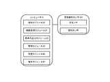
- FIG. 2 is an overall configuration diagram of the repair recording system 1.
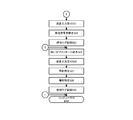
- FIG. 3 is a flowchart showing a repair record process executed by the computer 10.
- FIG. 4 is a flowchart showing a repair recording process executed by the computer 10.
- FIG. 5 is a diagram schematically illustrating an example of a state in which a repair worker is performing repair.
- FIG. 1 is a diagram for explaining an outline of a repair recording system 1 according to a preferred embodiment of the present invention.
- the repair recording system 1 is a computer system that includes a computer 10 and a replacement detection sensor 100 and records, for a repair target composed of a plurality of components, that the component has been repaired.
- repair record system 1 does not necessarily have to have the replacement detection sensor 100, and may include only the computer 10.
- the computer 10 detects an operation for repairing the component (for example, obtains a result of the replacement detection sensor 100 detecting that the component has been replaced). When the computer 10 detects that this operation has been performed, the computer 10 records the date and time when the operation is detected and the identification number of the repair target as a repair log. The repair log also records that the part has been recognized as being replaced.
- the computer 10 captures an image of the repair worker who has operated for repair by a photographing device such as a camera, recognizes the person of the repair worker, and records the recognized person in a repair log. .
- the computer 10 performs input / output of voice (for example, outputs a question, inputs a response to the question), obtains voice data of a reply from a repair worker, and adds the obtained voice data to a repair log. Record.
- voice for example, outputs a question, inputs a response to the question
- the replacement detection sensor 100 is a sensor capable of detecting an operation related to repair, such as an optical sensor or a contact sensor.
- an optical sensor detects opening and closing of an opening / closing door such as a hood of a machine body to be repaired.
- the contact sensor detects the attachment / detachment of a component or a device.
- the replacement detection sensor 100 transmits the detection result to the computer 10.
- the present invention is not limited to this example, and is applicable not only to construction machines, vehicles, moving bodies, and the like, but also to multifunction peripherals, office equipment, household electric appliances, and various articles requiring repair.
- the computer 10 detects that an operation for repairing the radiator component has been performed (step S01).
- the computer 10 detects an operation for repairing a part of the radiator by the replacement detection sensor 100.
- the computer 10 detects the opening and closing of the open / close door of the hood in which the radiator is stored by using an optical sensor. Further, the computer 10 detects the replacement of the radiator component by the contact sensor. At this time, the computer 10 detects that the radiator has been removed and attached again.
- the computer 10 When the computer 10 detects that this operation has been performed, the computer 10 records the detected date and time and the identification number of the radiator as a repair log (step S02). The computer 10 acquires the detected date and time from a timer or the like built in itself. Further, the computer 10 acquires the identification number of the radiator recorded in advance.
- the computer 10 may record the detected contents together with the repair log as recognition.
- the computer 10 captures a repair worker who has operated for repair by a photographing device such as a camera installed in the opening / closing section, and performs image analysis on the captured image to recognize a person of the repair worker.
- a photographing device such as a camera installed in the opening / closing section
- repair worker information such as the name and face of the recognized person may be recorded together with the repair log.
- the computer 10 inputs and outputs voices, asks the repair worker about the reason for operating the opening / closing door, such as "what kind of use is it?", And the reason for attaching / detaching the radiator, and acquires the voice of the answer to this question.
- the voice of the repair worker may be recognized by voice analysis of the voice, and the recognized answer may be recorded as repair worker information in the repair log.
- the repair log related to the repair target is recorded.
- the repair log may not be the repair target but may indicate which main body the machine or the like has accepted.
- a replacement detection sensor 100 may be installed in advance on each component (for example, an engine, a control board, or the like), and it may be recognized that the removal has been replaced, and this may be recorded as a repair log.
- FIG. 2 is a diagram showing a system configuration of a repair recording system 1 according to a preferred embodiment of the present invention.
- a repair recording system 1 is a computer system that includes a computer 10 and a replacement detection sensor 100 and records, as a repair log, a repair target for a repair target composed of a plurality of components. is there.
- the computer 10 includes a CPU (Central Processing Unit), a RAM (Random Access Memory), a ROM (Read Only Memory), and the like as a control unit, and other devices (an imaging device, a sound collecting device, a sound emitting device) as a communication unit. Etc.) and a device for enabling communication with the exchange detection sensor 100, for example, a device compatible with Wi-Fi (Wireless-Fidelity) compliant with IEEE802.11.
- the computer 10 includes, as a recording unit, a data storage unit such as a hard disk, a semiconductor memory, a recording medium, and a memory card.
- the computer 10 includes, as a processing unit, various devices and the like for executing image and voice recognition processing, various determination processing, and the like.
- control module reads a predetermined program, and realizes the detection module 20, the image acquisition module 21, and the voice input / output module 22 in cooperation with the communication section. Further, in the computer 10, the control unit reads a predetermined program, thereby realizing the recording module 30 in cooperation with the recording unit. In the computer 10, the control unit reads a predetermined program, and realizes the specific module 40 and the analysis module 41 in cooperation with the processing unit.
- the replacement detection sensor 100 is a detector that detects contact, light, electricity, and the like.
- the replacement detection sensor 100 is, for example, an optical sensor or a contact sensor.
- the replacement detection sensor 100 transmits its detection result to the computer 10.
- the repair record system 1 detects an operation for repair or replacement of a part by the computer 10 acquiring a detection result of the replacement detection sensor 100. Further, the repair recording system 1 includes an image capturing device such as a camera, a sound emitting device such as a speaker, and a sound collecting device such as a microphone, which are connected to the computer 10 so that data communication is possible. The repair recording system 1 captures an image of a repair worker using an imaging device, and the computer 10 acquires the image and analyzes the image to perform person recognition. Further, the repair recording system 1 outputs a question by voice to the repair worker by using a sound emitting device, inputs an answer to the question by using a sound collecting device, the computer 10 acquires the answer, and performs voice analysis. By doing so, speech recognition is performed.
- an image capturing device such as a camera
- a sound emitting device such as a speaker
- a sound collecting device such as a microphone
- FIG. 3 is a diagram illustrating a flowchart of the repair recording process executed by the computer 10. The processing executed by each module described above will be described together with this processing.
- the repair target is a shovel car and the failed part is a radiator part.
- the detection module 20 determines whether an operation for repairing a component has been detected (step S10).
- step S10 the detection module 20 determines whether or not an operation for repairing a radiator component has been performed.
- this operation is the opening and closing of an opening / closing door such as a hood provided in a place where the radiator is stored.
- the detection module 20 determines the presence or absence of an operation by acquiring the detection result of the replacement detection sensor 100 (optical sensor) provided at this location. Specifically, the detection module 20 obtains the detection result of the replacement detection sensor 100, and determines whether the operation is detected by determining whether the detection result is light. Judge.
- the detection module 20 does not detect the repair of the component itself, but detects an operation necessary to repair the component.
- step S10 if the detection module 20 determines that the operation for repairing the component has not been detected (step S10 NO), that is, if it has not been detected that the opening / closing door has been opened, the processing ends. I do.
- step S10 when the detection module 20 determines that the operation for repairing the component has been detected (step S10: YES), that is, when it is detected that the opening / closing door is opened, the specific module 40 This operation is specified (step S11).
- step S11 the specifying module 40 specifies an operation based on which exchange detection sensor 100 has obtained the detection result.
- the detection module 20 obtains, as a detection result, that the open / close door is opened from the optical sensor as the replacement detection sensor 100, the radiator which is a component inside the place where the open / close door is provided is provided. It is specified that an operation for repairing is detected.
- the specifying module 40 specifies that an operation for repairing any of the plurality of components or repairing the place itself is detected. I do.
- the recording module 30 records the specified result as a repair log (Step S12).
- the recording module 30 records the identified operation, the date and time when the operation was detected, and the identification number of the repair target in association with each other as a repair log.
- the recording module 30 acquires the date and time when this operation is detected from a timer or the like built in the recording module 30.
- the recording module 30 refers to the identification number of each component recorded in advance by itself, and acquires the identification number of the current repair target.
- the recording module 30 records the specified operation as a repair log in association with the operation for repairing the radiator, the acquired date and time, and the identification number of the radiator.
- a repair operation is performed on a group of these parts, a date and time when the operation is detected, and respective identification numbers of the parts are recorded as a repair log.
- the repair operation, the date and time, and the identification number for each of them may be associated with each other and recorded as a repair log.
- the detection module 20 determines whether or not a component replacement operation has been detected (step S13).
- step S13 the detection module 20 determines whether or not an operation of replacing a radiator component has been detected.
- the operation of replacing parts of the radiator is the attachment and detachment of the radiator.
- the detection module 20 determines the presence or absence of this operation by acquiring the detection result of the replacement detection sensor 100 (contact sensor) disposed at the location where the radiator is disposed. Specifically, the detection module 20 obtains the detection result of the replacement detection sensor 100, and determines whether this operation has been detected by determining whether the radiator has been removed and attached again, based on the detection result. Determine whether or not.
- the detection module 20 detects the repair of the component itself. That is, when detecting or removing the radiator, the detection module 20 determines that the repair target component has been repaired.
- step S13 when the detection module 20 determines that the replacement operation of the component has not been detected (step S13: NO), that is, when the attachment / detachment of the radiator cannot be detected, the component to be repaired is not repaired. It is determined that the process has been completed, and the present process ends.
- step S13 when the detection module 20 determines that the operation of replacing the component has been detected (step S13: YES), that is, when it is possible to detect the attachment / detachment of the radiator, the identification module 40 identifies this operation. (Step S14).
- the specifying module 40 specifies an operation based on which exchange detection sensor 100 has obtained the detection result.
- the identification module 40 as the replacement detection sensor 100, acquires the attachment / detachment of the radiator from the contact sensor as a detection result, and thus specifies that the operation for replacing the radiator has been detected.
- the specific module 40 recognizes that the component has been replaced by the replacement detection sensor 100 in this manner.
- the recording module 30 records the repair log described above in association with the content of the replacement operation of the component specified this time (step S15).
- the recording module 30 records, as a repair log, the specified operation, the content of the replaced component, the date and time when the operation was detected, and the identification number of the repair target in association with each other.
- the recording module 30 deletes the repair log recorded by the processing in step S12 described above, and records only the repair log recorded this time. That is, the above-described repair log relating only to the operation of repairing the component which is the premise of executing the operation of replacing the component specified this time is deleted, and the current repair log is recorded.
- the recording module 30 may be configured to simultaneously record the repair log obtained in step S12 and the repair log obtained in step S15.
- the image acquisition module 21 acquires an image such as a moving image or a still image of the repair worker (step S16). In step S16, the image acquisition module 21 acquires an image of the repair worker photographed by the photographing device mounted inside the opening / closing section. This image only needs to show at least the face of the repair worker.
- the installation location of the imaging device can be changed as appropriate.
- the analysis module 41 analyzes the acquired image to recognize the face of the repair worker (step S17).
- the analysis module 41 extracts one or both of the feature points and the feature amounts of the image.
- the analysis module 41 extracts shapes, brightness, colors, contours, and the like included in the image as feature points.
- the analysis module 41 extracts statistical numerical values such as various numerical values (average, variance, and histogram of pixel values) calculated from the image as the feature amount.
- the analysis module 41 recognizes the face of the repair worker in the image based on the analysis result.
- the identification module 40 attempts to identify the repair worker based on the recognized face of the repair worker (step S18).
- step S ⁇ b> 18 the specific module 40 compares the recognized face of the repair worker with the face image of the delivery destination person to be repaired or the face image of the repair worker dispatched by the manufacturer, which is recorded in the recording module 30 in advance. In this way, an attempt is made to identify the repair worker at this time.
- the face image recorded by the recording module 30 is associated with the name and affiliation of the person of the face image, and the identification module 40 identifies the repair worker as the face image and the name of the repair worker. Attempt to identify worker information.
- the identification module 40 determines whether the repair worker has been identified (step S19). In step S19, the specifying module 40 determines whether or not the repair worker corresponds to the recorded person based on the recognized face of the repair worker.
- the specifying module 40 determines that the repair worker could not be specified (step S19 NO), and The input / output module 22 causes the sound emitting device to output an inquiry message for asking who the repair worker is (step S20).
- the voice input / output module 22 outputs a voice message asking for the name of the repair worker such as "Where are you opening the hood?" Output via the device. This voice message is output for the purpose of specifying who the repair worker is.
- the voice input / output module 22 receives an input of a response to the voice message as voice data (step S21).
- the voice input / output module 22 collects a voice of a reply to the voice message issued by the repair worker with a sound collection device, and receives the input as voice data.
- the audio input / output module 22 proceeds to the process of step S22 described later.
- the analysis module 41 specifies a repair worker by performing voice analysis on the voice data received as input (step S22).
- the analysis module 41 extracts a voice and an environmental sound by analyzing a waveform of the voice in the voice data.
- the analysis module 41 recognizes the name of the repair worker included in the voice as the analysis result of the voice data, and specifies the name of the repair worker and the recognized face as the repair worker information.
- the analysis module 41 specifies that the repair worker information is unknown when the name of the repair worker is not recognized or when the input of the voice data is not received even after a predetermined time has elapsed.
- the recording module 30 records the repair operator information specified this time in association with the repair log described above (step S23).
- the recording module 30 stores the specified operation as the repair log, the content of the replaced part, the specified repair worker information (the name and face of the repair worker or the repair worker is unknown), Is recorded in association with the date and time when the is detected and the identification number of the repair target.
- the recording module 30 deletes the repair log recorded by the processing in step S15 described above, and records only the repair log recorded this time. That is, the above-described repair log before the repair log in which the repair worker information specified this time is also recorded is deleted, and the current repair log is recorded.
- the recording module 30 may be configured to simultaneously record the repair logs in Steps S12 and S15 without deleting them.
- step S23 After the computer 10 executes the process of step S23 described above, the computer 10 executes the process of step S25 described later.
- step S19 when the person corresponding to the recording module 30 has the face of the repair worker in the image recorded therein, the specifying module 40 determines that the repair worker has been specified (step S19 YES), The recording module 30 records the repair operator information specified this time in association with the repair log described above (step S24).
- step S24 the recording module 30 determines, as the repair log, the specified operation, the content of the replaced part, the specified repair worker information (name and face of the repair worker), the date and time when this operation was detected, The identification number of the repair target is recorded in association with the identification number.
- the recording module 30 deletes the repair log recorded by the processing in step S15 described above, and records only the repair log recorded this time. That is, the above-described repair log before the repair log in which the repair worker information specified this time is also recorded is deleted, and the current repair log is recorded.
- the voice input / output module 22 causes the sound emitting device to output an interrogation message for inquiring about a task (step S25).
- the voice input / output module 22 outputs a voice message inquiring about the task of the repair worker, such as "What kind of use is it?", Via the sound emitting device installed at the above-mentioned location. This voice message is output for the purpose of specifying the task of the repair worker.
- the voice input / output module 22 receives an input of a response to the voice message as voice data (step S26).
- the voice input / output module 22 receives an input of the reply of the repair worker as voice data by a process similar to the process of step S21 described above.
- the analysis module 41 performs voice analysis on the received voice data to specify the task of the repair worker (step S27).
- step S27 the same processing as the above-described processing in step S22 is executed, the task of the repair worker included in the voice is recognized, and the task of the repair worker is specified as the repair worker information.
- the analysis module 41 specifies that the repair worker information is unknown when the task of the repair worker cannot be recognized or when the input of the voice data is not received even after a predetermined time has elapsed.
- the identification module 40 identifies its own location (step S28).
- the specifying module 40 obtains its own position information from GPS (Global Positioning System) or the like, and specifies its own current location based on this position information.
- GPS Global Positioning System
- the recording module 30 records the repair operator information specified this time and the specified own location together with the repair log described above in association with each other (step S29).
- step S29 the recording module 30 stores, as the repair log, the specified operation, the content of the replaced part, the specified repair worker information (adding a task to the above), and the date and time when the operation was detected.
- the identified location and the identification number of the repair target are recorded in association with each other.
- the recording module 30 deletes the repair log recorded by the processing in step S23 or S24 described above, and records only the repair log recorded this time. That is, the above-described repair log before the repair log in which the repair worker information specified this time is also recorded is deleted, and the current repair log is recorded.
- the recording module 30 may be configured to record the repair logs in the processes of steps S12, S15, and S23 or S24 simultaneously without deleting them.
- FIG. 5 is a diagram schematically illustrating an example of a state in which a repair worker is performing repair.
- a repair worker 210 there are a repair worker 210, a shovel car 220 to be repaired, and a radiator 230 to be replaced.
- the repair worker 210 opens and closes the door 240 of the shovel car 220.
- the replacement detection sensor 100 (optical sensor) detects the opening and closing of the door 240.
- the specifying module 40 specifies that an operation for repairing the radiator 230 inside the place has been performed based on the detection result that the opening / closing door 240 has been opened.
- the recording module 30 records the specified result as a repair log. At this time, the recording module 30 records an operation for repairing the radiator 230 as the specified operation. The recording module 30 records the current date and time (13:00 on May 30, 2018) as the date and time when this operation was detected. Further, the recording module 30 records the identification number (AA-BB11-ABCD) of the radiator 230.
- the replacement detection sensor 100 detects the attachment / detachment of the radiator 230.
- the specifying module 40 specifies that the radiator 230 has been replaced based on a detection result that the radiator 230 has been removed and attached again.
- the recording module 30 further records the specified result as a repair log. At this time, the result specified this time is also recorded in the repair log described above. That is, as the repair log, the specified operation, the content of the replaced part (replacement of the radiator 230), the date and time when this operation is detected, and the identification number of the repair target are recorded in association with each other.
- the image acquisition module 21 acquires an image of the repair worker 210 photographed by the photographing device 250 installed in the opening / closing section.
- the specifying module 40 and the analyzing module 41 specify the repair worker information (name and face) based on the face of the repair worker 210 recognized by the image analysis.
- the voice input / output module 22 outputs a voice message to the repair worker 210 via the sound emitting device 260, and receives an input of a reply to the voice message from the repair worker 210 via the sound collecting device 270.
- the voice message is intended to identify the repair worker 210 when the repair worker 210 is not specified.
- the identification module 40 identifies the repair worker information (name and face) based on the response recognized by the analysis module 41 by the voice analysis.
- the recording module 30 records the repair worker information specified this time together with the repair log described above. That is, as the repair log, the specified operation, the content of the replaced part, the specified repair worker information (name and image of the repair worker 210), the date and time when this operation was detected, the identification number of the repair target, Are recorded in association with each other.
- the voice input / output module 22 outputs a voice message to the repair worker 210 via the sound emitting device 260, and receives an input of a reply to the voice message from the repair worker 210 via the sound collecting device 270.
- the voice message at this time is intended to specify the task of the repair worker 210.
- the specifying module 40 specifies the repair worker information (business) of the repair worker 210 based on the answer recognized by the analysis module 41 by the voice analysis.
- the identification module 40 acquires its own location from a GPS or the like and identifies the current location.
- the recording module 30 records the repair operator information specified this time and the specified own location together with the repair log described above. That is, as the repair log, the specified operation, the content of the replaced part, the specified repair worker information (name, image, and task of the repair worker 210), the date and time when this operation was detected, the repair target The identification number is recorded in association with the identification number.
- the repair log related to the repair target is recorded.
- the repair log may not be the repair target but may indicate which main body the machine or the like has accepted.
- a replacement detection sensor 100 may be installed in advance on each component (for example, an engine, a control board, or the like), and it may be recognized that the removal has been replaced, and this may be recorded as a repair log.
- the computer 10 may be configured to transmit the recording log recorded by the recording module 30 to an external recording device such as a cloud.
- the present invention is not limited to this example, and is applicable not only to construction machines, vehicles, moving bodies, and the like, but also to multifunction peripherals, office equipment, household electric appliances, and various articles requiring repair.
- the means and functions described above are realized by a computer (including a CPU, an information processing device, and various terminals) reading and executing a predetermined program.
- the program is provided, for example, in a form of being provided from a computer via a network (SaaS: Software as a Service).
- the program is provided in a form recorded on a computer-readable recording medium such as a flexible disk, a CD (eg, a CD-ROM), and a DVD (eg, a DVD-ROM, a DVD-RAM).
- the computer reads the program from the recording medium, transfers the program to an internal recording device or an external recording device, records the program, and executes the program.
- the program may be recorded in a recording device (recording medium) such as a magnetic disk, an optical disk, and a magneto-optical disk in advance, and may be provided to the computer from the recording device via a communication line.
- the present invention is not limited to these embodiments.
- the effects described in the embodiments of the present invention merely enumerate the most preferable effects resulting from the present invention, and the effects according to the present invention are limited to those described in the embodiments of the present invention. is not.
Landscapes
- Engineering & Computer Science (AREA)
- Theoretical Computer Science (AREA)
- Quality & Reliability (AREA)
- General Engineering & Computer Science (AREA)
- Business, Economics & Management (AREA)
- General Physics & Mathematics (AREA)
- Physics & Mathematics (AREA)
- Human Resources & Organizations (AREA)
- Strategic Management (AREA)
- Tourism & Hospitality (AREA)
- Operations Research (AREA)
- General Business, Economics & Management (AREA)
- Marketing (AREA)
- Entrepreneurship & Innovation (AREA)
- Computer Hardware Design (AREA)
- Economics (AREA)
- Mechanical Engineering (AREA)
- Management, Administration, Business Operations System, And Electronic Commerce (AREA)
- Debugging And Monitoring (AREA)
Abstract
【課題】特定の操作が行われたことを検知することにより、修理の実態を把握することが可能なコンピュータシステム、修理記録方法及びプログラムを提供することを目的とする。 【解決手段】複数の部品で構成する修理対象に対して、当該部品が修理を受けたことを記録するコンピュータシステムは、前記部品を修理するための操作があったことを検知し、前記操作があったことを検知した場合に、検知した日時と、前記修理対象の識別番号とを記録する。また、コンピュータシステムは、部品が交換されたことを検知する交換検知センサを備え、この交換検知センサにより部品が交換されたと認識したことを記録する。
Description
本発明は、複数の部品で構成する修理対象に対して、この部品が修理を受けたことを記録するコンピュータシステム、修理記録方法及びプログラムに関する。
従来、建機や車両等が故障した際、メーカに連絡を取り、このメーカから派遣された修理作業者が故障の修理を行っている。しかしながら、建機や車両等の故障時、メーカに連絡を取らず、取扱代理店やこの建機や車両等の使用者が故障の内容を判断し、勝手に修理をしてしまうことがあった。そのため、メーカ側が実際の故障や修理の実態を、把握できないおそれがあった。
そこで、修理ログを記録することにより、メーカ側が連絡を受けなくても、故障や修理の内容を把握することが行われていた。
このような修理ログを記録するシステムとして、部品交換が行われた際に、メンテナンス作業として行われた部品交換と、メンテナンス作業ではなく行われた部品交換との其々のタイミングで、履歴を修理ログとして記録することが開示されている(特許文献1参照)。
しかしながら、特許文献1の構成では、部品交換が行われたタイミングの修理ログは記録されるものの、この修理ログを行った人物がメーカから派遣された修理作業者であるかが記録されないことに加え、どのような理由や作業内容であったのかを把握することが困難であることから、メーカ側が修理の実態を把握することが困難であった。
本発明は、特定の操作が行われたことを検知することにより、修理の実態を把握することが可能なコンピュータシステム、修理記録方法及びプログラムを提供することを目的とする。
本発明では、以下のような解決手段を提供する。
本発明は、複数の部品で構成する修理対象に対して、当該部品が修理を受けたことを記録するコンピュータシステムであって、
前記部品を修理するための操作があったことを検知する検知手段と、
前記操作があったことを検知した場合に、検知した日時と、前記修理対象の識別番号とを記録する記録手段と、
を備えることを特徴とするコンピュータシステムを提供する。
前記部品を修理するための操作があったことを検知する検知手段と、
前記操作があったことを検知した場合に、検知した日時と、前記修理対象の識別番号とを記録する記録手段と、
を備えることを特徴とするコンピュータシステムを提供する。
本発明によれば、複数の部品で構成する修理対象に対して、当該部品が修理を受けたことを記録するコンピュータシステムは、前記部品を修理するための操作があったことを検知し、前記操作があったことを検知した場合に、検知した日時と、前記修理対象の識別番号とを記録する。
本発明は、コンピュータシステムのカテゴリであるが、方法及びプログラム等の他のカテゴリにおいても、そのカテゴリに応じた同様の作用・効果を発揮する。
本発明によれば、特定の操作が行われたことを検知することにより、修理の実態を把握することが可能なコンピュータシステム、修理記録方法及びプログラムを提供することが可能となる。
以下、本発明を実施するための最良の形態について図を参照しながら説明する。なお、これはあくまでも一例であって、本発明の技術的範囲はこれらに限られるものではない。
[修理記録システム1の概要]
本発明の好適な実施形態の概要について、図1に基づいて説明する。図1は、本発明の好適な実施形態である修理記録システム1の概要を説明するための図である。修理記録システム1は、コンピュータ10及び交換検知センサ100から構成され、複数の部品で構成する修理対象に対して、この部品が修理を受けたことを記録するコンピュータシステムである。
本発明の好適な実施形態の概要について、図1に基づいて説明する。図1は、本発明の好適な実施形態である修理記録システム1の概要を説明するための図である。修理記録システム1は、コンピュータ10及び交換検知センサ100から構成され、複数の部品で構成する修理対象に対して、この部品が修理を受けたことを記録するコンピュータシステムである。
なお、修理記録システム1は、必ずしも交換検知センサ100を有する構成でなくてもよく、コンピュータ10のみから構成されてもよい。
コンピュータ10は、部品を修理するための操作を検知(例えば、交換検知センサ100が、部品が交換されたことを検知した結果を取得)する。コンピュータ10は、この操作があったことを検知した場合、この操作を検知した日時と、修理対象の識別番号とを修理ログとして記録する。この修理ログは、部品が交換されたと認識したことも併せて記録される。
また、コンピュータ10は、修理のために操作した修理作業者の画像をカメラ等の撮影装置により撮影し、この修理作業者の人物の認識を行い、この認識した人物を修理ログに併せて記録する。
また、コンピュータ10は、音声の入出力(例えば、問いかけを出力、この問いかけの返答を入力)を行い、修理作業者から回答の音声データを取得し、この取得した音声データを修理ログに併せて記録する。
交換検知センサ100は、光センサや接触センサ等の修理に関連した操作を検知することが可能なセンサである。例えば、光センサが、修理対象の機械本体のボンネット等の開閉扉の開閉を検知する。また、接触センサが、部品や装置等の脱着を検知する。交換検知センサ100は、検知した結果を、コンピュータ10に送信する。
修理記録システム1が実行する処理の概要について説明する。以下の説明において、修理対象がショベルカーであり、故障部分がラジエータの部品であるものとして説明する。
なお、本発明は、この例に限らず、建設機械、車両、移動体等に限らず、複合機、事務機器、家庭用電気機器、修理が必要な様々な物品に対して適用可能である。
コンピュータ10は、ラジエータの部品を修理するための操作があったことを検知する(ステップS01)。コンピュータ10は、交換検知センサ100によりラジエータの部品を修理するための操作を検知する。ここでは、コンピュータ10は、ラジエータの確認のために、このラジエータが格納されたボンネットの開閉扉の開閉を、光センサにより検知する。また、コンピュータ10は、ラジエータの部品の交換を、接触センサにより検知する。このとき、コンピュータ10は、ラジエータが取り外され、再度、装着されたことを、検知する。
コンピュータ10は、この操作があったことを検知した場合、検知した日時と、ラジエータの識別番号とを修理ログとして記録する(ステップS02)。コンピュータ10は、検知した日時を、自身が内蔵するタイマー等から取得する。また、コンピュータ10は、予め記録したこのラジエータの識別番号を取得する。
コンピュータ10は、接触センサによりラジエータの脱着を検知した場合、この検知した内容を認識したと修理ログに併せて記録してもよい。
また、コンピュータ10は、修理のために操作した修理作業者を、開閉部に設置したカメラ等の撮影装置により撮影し、撮影した画像を画像解析することにより、修理作業者の人物の認識を行い、この認識した人物の名前や顔といった修理作業者情報を、修理ログに併せて記録してもよい。
また、コンピュータ10は、音声の入出力を行い、修理作業者に対して「どんな御用ですか?」等の開閉扉の操作やラジエータの脱着の理由を問いかけ、この問いかけに対する回答の音声を取得し、この音声を音声解析することにより、修理作業者の回答の認識を行い、この認識した回答を、修理作業者情報として修理ログに併せて記録してもよい。
なお、上述した例では、修理対象に関した修理ログを記録しているが、修理対象ではなく、機械等がどの本体に対する操作を受け付けたかを修理ログとして記録してもよい。また、各部品(例えば、エンジンやコントロールボード等)に予め交換検知センサ100を設置しておき、取り外されたことを交換されたと認識し、これを修理ログとして記録してもよい。
以上が、修理記録システム1の概要である。
[修理記録システム1のシステム構成]
図2に基づいて、本発明の好適な実施形態である修理記録システム1のシステム構成について説明する。図2は、本発明の好適な実施形態である修理記録システム1のシステム構成を示す図である。図2において、修理記録システム1は、コンピュータ10及び交換検知センサ100から構成され、複数の部品で構成する修理対象に対して、この部品が修理を受けたことを修理ログとして記録するコンピュータシステムである。
図2に基づいて、本発明の好適な実施形態である修理記録システム1のシステム構成について説明する。図2は、本発明の好適な実施形態である修理記録システム1のシステム構成を示す図である。図2において、修理記録システム1は、コンピュータ10及び交換検知センサ100から構成され、複数の部品で構成する修理対象に対して、この部品が修理を受けたことを修理ログとして記録するコンピュータシステムである。
コンピュータ10は、制御部として、CPU(Central Processing Unit)、RAM(Random Access Memory)、ROM(Read Only Memory)等を備え、通信部として、他の機器(撮影装置、集音装置、放音装置等)や交換検知センサ100と通信可能にするためのデバイス、例えば、IEEE802.11に準拠したWi―Fi(Wireless―Fidelity)対応デバイス等を備える。また、コンピュータ10は、記録部として、ハードディスクや半導体メモリ、記録媒体、メモリカード等によるデータのストレージ部を備える。また、コンピュータ10は、処理部として、画像や音声の認識処理、各種判断処理等を実行する各種デバイス等を備える。
コンピュータ10において、制御部が所定のプログラムを読み込むことにより、通信部と協働して、検知モジュール20、画像取得モジュール21、音声入出力モジュール22を実現する。また、コンピュータ10において、制御部が所定のプログラムを読み込むことにより、記録部と協働して、記録モジュール30を実現する。また、コンピュータ10において、制御部が所定のプログラムを読み込むことにより、処理部と協働して、特定モジュール40、解析モジュール41を実現する。
交換検知センサ100は、接触、光、電気等を検知する検知器である。交換検知センサ100は、例えば、光センサ、接触センサである。交換検知センサ100は、自身の検知結果を、コンピュータ10に送信する。
修理記録システム1は、交換検知センサ100の検知結果を、コンピュータ10が取得することにより、修理のための操作を検知や部品の交換を検知する。また、修理記録システム1は、コンピュータ10とデータ通信可能に接続されたカメラ等の撮影装置や、スピーカ等の放音装置や、マイク等の集音装置等を有する。修理記録システム1は、撮影装置により、修理作業者の画像を撮影し、コンピュータ10がこの画像を取得し、画像解析することにより、人物認識を行う。また、修理記録システム1は、放音装置により、修理作業者に対して、音声で問いかけを出力し、集音装置によりこの問いかけに対する回答を入力し、コンピュータ10がこの回答を取得し、音声解析することにより、音声認識を行う。
[修理記録処理]
図3に基づいて、修理記録システム1が実行する修理記録処理について説明する。図3は、コンピュータ10が実行する修理記録処理のフローチャートを示す図である。上述した各モジュールが実行する処理について、本処理に併せて説明する。
図3に基づいて、修理記録システム1が実行する修理記録処理について説明する。図3は、コンピュータ10が実行する修理記録処理のフローチャートを示す図である。上述した各モジュールが実行する処理について、本処理に併せて説明する。
以下の説明において、修理対象がショベルカーであり、故障部分がラジエータの部品であるものとして説明する。
はじめに、検知モジュール20は、部品を修理するための操作を検知したか否かを判断する(ステップS10)。ステップS10において、検知モジュール20は、ラジエータの部品を修理するための操作があったか否かを判断する。ここで、この操作とは、ラジエータが格納された場所に設けられたボンネット等の開閉扉の開閉である。検知モジュール20は、この場所に設けられた交換検知センサ100(光センサ)の検知結果を取得することにより、操作の有無を判断する。具体的には、検知モジュール20は、交換検知センサ100の検知結果を取得し、この検知結果が、光を検知したものであるか否かを判断することにより、この操作を検知したか否かを判断する。
本ステップにおいて、検知モジュール20は、部品の修理そのものの検知をするのではなく、この部品を修理するために必要な操作を検知する。
ステップS10において、検知モジュール20は、部品を修理するための操作を検知できなかったと判断した場合(ステップS10 NO)、すなわち、開閉扉が開けられたことを検知できなかった場合、本処理を終了する。
一方、ステップS10において、検知モジュール20は、部品を修理するための操作を検知できたと判断した場合(ステップS10 YES)、すなわち、開閉扉が開けられたことを検知できた場合、特定モジュール40は、この操作を特定する(ステップS11)。ステップS11において、特定モジュール40は、どの交換検知センサ100からこの検知結果を取得したかに基づいて、操作を特定する。上述した例では、検知モジュール20は、交換検知センサ100として光センサから開閉扉が開けられたことを検知結果として取得したことから、この開閉扉が設けられた場所の内部にある部品であるラジエータを修理するための操作を検知したと特定する。
特定モジュール40は、この開閉扉が設けられた場所の内部に複数の部品が存在する場合、この複数の部品の何れかを修理するため又はこの場所そのものを修理するための操作を検知したと特定する。
記録モジュール30は、この特定した結果を、修理ログとして記録する(ステップS12)。ステップS12において、記録モジュール30は、修理ログとして、特定した操作と、この操作を検知した日時と、修理対象の識別番号とを対応付けて記録する。記録モジュール30は、自身が内蔵するタイマー等からこの操作を検知した日時を取得する。記録モジュール30は、自身が予め記録した各部品の識別番号を参照し、今回の修理対象の識別番号を取得する。
上述した例では、記録モジュール30は、特定した操作として、ラジエータを修理するための操作、取得した日時及びこのラジエータの識別番号を対応付けて修理ログとして記録する。
なお、複数の部品が存在する場合、これらを一のグループとしてまとめたものに対する修理操作と、この操作を検知した日時と、複数の部品の各識別番号とを対応付けて修理ログとして記録する。また、複数の部品が存在する場合、其々に対する修理操作と、日時と、識別番号とを対応付けて修理ログとして記録してもよい。
検知モジュール20は、部品の交換の操作を検知したか否かを判断する(ステップS13)。ステップS13において、検知モジュール20は、ラジエータの部品の交換を行う操作を検知したか否かを判断する。ここで、このラジエータの部品の交換を行う操作とは、ラジエータの脱着である。検知モジュール20は、このラジエータが配置されている箇所に配置された交換検知センサ100(接触センサ)の検知結果を取得することにより、この操作の有無を判断する。具体的には、検知モジュール20は、交換検知センサ100の検知結果を取得し、この検知結果が、ラジエータが取り外され、再度、装着されたか否かを判断することにより、この操作を検知したか否かを判断する。
本ステップにおいて、検知モジュール20は、部品の修理そのものを検知する。すなわち、検知モジュール20は、ラジエータの脱着を検知した場合、修理対象の部品の修理が行われたと判断する。
ステップS13において、検知モジュール20は、部品の交換の操作を検知できなかったと判断した場合(ステップS13 NO)、すなわち、ラジエータの脱着を検知できなかった場合、修理対象の部品の修理が行われなかったと判断し、本処理を終了する。
一方、ステップS13において、検知モジュール20は、部品の交換の操作を検知できたと判断した場合(ステップS13 YES)、すなわち、ラジエータの脱着を検知できた場合、特定モジュール40は、この操作を特定する(ステップS14)。ステップS14において、特定モジュール40は、この検知結果を、どの交換検知センサ100から取得したかに基づいて、操作を特定する。上述した例では、特定モジュール40は、交換検知センサ100として、接触センサからラジエータの脱着を検知結果として取得したことから、このラジエータの交換するための操作を検知したと特定する。
特定モジュール40は、このようにすることにより、交換検知センサ100により部品が交換されたことを認識する。
記録モジュール30は、上述した修理ログに、今回特定した部品の交換の操作内容を併せて対応付けて記録する(ステップS15)。ステップS15において、記録モジュール30は、修理ログとして、特定した操作と、交換した部品の内容と、この操作を検知した日時と、修理対象の識別番号とを対応付けて記録する。このとき、記録モジュール30は、上述したステップS12の処理により記録した修理ログを削除し、今回記録した修理ログのみを記録する。すなわち、今回特定した部品の交換の操作内容を実行する前提となる部品を修理する操作のみに関する上述した修理ログを削除し、今回の修理ログを記録する。
なお、記録モジュール30は、ステップS12の処理による修理ログと、ステップS15の処理による修理ログとを同時に記録する構成であってもよい。
画像取得モジュール21は、修理作業者の動画や静止画等の画像を取得する(ステップS16)。ステップS16において、画像取得モジュール21は、開閉部の内側に取り付けられた撮影装置が撮影した修理作業者の画像を取得する。この画像は、少なくとも修理作業者の顔が写っていればよい。
なお、撮影装置の設置場所は適宜変更可能である。
解析モジュール41は、取得した画像を画像解析し、修理作業者の顔を認識する(ステップS17)。ステップS17において、解析モジュール41は、この画像の特徴点又は特徴量の何れか又は双方を抽出する。解析モジュール41は、特徴点として、画像に含まれる形状、輝度、色、輪郭等を抽出する。また、解析モジュール41は、特徴量として、画像から算出した各種数値(画素値の平均、分散、ヒストグラム)等の統計的な数値を抽出する。解析モジュール41は、この解析結果に基づいて、この画像に写っている修理作業者の顔を認識する。
特定モジュール40は、認識した修理作業者の顔に基づいて、この修理作業者の特定を試みる(ステップS18)。ステップS18において、特定モジュール40は、認識した修理作業者の顔と、予め記録モジュール30に記録した修理対象の納入先の人物の顔画像やメーカ側が派遣する修理作業者の顔画像とを比較することにより、今回の修理作業者の特定を試みる。このとき、記録モジュール30が記録する顔画像には、この顔画像の人物の名前や所属等が対応付けられており、特定モジュール40は、修理作業者の特定として、顔画像及び名前である修理作業者情報の特定を試みる。
特定モジュール40は、修理作業者を特定できたか否かを判断する(ステップS19)。ステップS19において、特定モジュール40は、認識した修理作業者の顔に基づいて、この修理作業者が記録された人物に該当するか否かを判断する。
特定モジュール40は、画像に写った修理作業者の顔が不鮮明な場合又は記録モジュール30に該当する人物が記録されていない場合、修理作業者を特定できなかったと判断し(ステップS19 NO)、音声入出力モジュール22は、放音装置から修理作業者が誰であるのかを問いかける問いかけメッセージを出力させる(ステップS20)。ステップS20において、音声入出力モジュール22は、「ボンネットを開けましたね、あなたはどなたですか?」といった修理作業者の名前を問いかける音声メッセージを、修理対象又は故障部分の近傍に設置された放音装置を介して出力する。この音声メッセージは、修理作業者が誰であるかを特定することを目的として出力されるものである。
音声入出力モジュール22は、この音声メッセージに対する返答を音声データとして入力を受け付ける(ステップS21)。ステップS21において、音声入出力モジュール22は、修理作業者が発した音声メッセージに対する返答の音声を、集音装置により集音し、この音声を音声データとして入力を受け付ける。
このとき、音声入出力モジュール22は、所定時間経過しても、音声データの入力を受け付けなかった場合、後述するステップS22の処理に移行する。
解析モジュール41は、入力を受け付けた音声データを音声解析することにより、修理作業者を特定する(ステップS22)。ステップS22において、解析モジュール41は、音声データにおける音声の波形を解析することにより、音声と環境音とを抽出する。解析モジュール41は、音声データの解析結果として、この音声に含まれる修理作業者の名前を認識し、この修理作業者の名前及び認識した顔を修理作業者情報として特定する。また、解析モジュール41は、修理作業者の名前が認識できなかった場合又は所定時間経過しても、音声データの入力を受け付けなかった場合、修理作業者情報が不明であると特定する。
記録モジュール30は、上述した修理ログに、今回特定した修理作業者情報を併せて対応付けて記録する(ステップS23)。ステップS23において、記録モジュール30は、修理ログとして、特定した操作と、交換した部品の内容と、特定した修理作業者情報(修理作業者の名前と顔又は修理作業者が不明)と、この操作を検知した日時と、修理対象の識別番号とを対応付けて記録する。このとき、記録モジュール30は、上述したステップS15の処理により記録した修理ログを削除し、今回記録した修理ログのみを記録する。すなわち、今回特定した修理作業者情報を併せて記録した修理ログ以前の上述した修理ログを削除し、今回の修理ログを記録する。
なお、記録モジュール30は、ステップS12及びS15の処理による修理ログを削除せずに、同時に記録する構成であってもよい。
コンピュータ10は、上述したステップS23の処理を実行した後、後述するステップS25の処理を実行する。
一方、ステップS19において、特定モジュール40は、画像に写った修理作業者の顔が記録モジュール30に該当する人物が記録されている場合、修理作業者を特定できたと判断し(ステップS19 YES)、記録モジュール30は、上述した修理ログに、今回特定した修理作業者情報を併せて対応付けて記録する(ステップS24)。ステップS24において、記録モジュール30は、修理ログとして、特定した操作と、交換した部品の内容と、特定した修理作業者情報(修理作業者の名前と顔)と、この操作を検知した日時と、修理対象の識別番号とを対応付けて記録する。このとき、記録モジュール30は、上述したステップS15の処理により記録した修理ログを削除し、今回記録した修理ログのみを記録する。すなわち、今回特定した修理作業者情報を併せて記録した修理ログ以前の上述した修理ログを削除し、今回の修理ログを記録する。
音声入出力モジュール22は、放音装置から用件を問いかける問いかけメッセージを出力させる(ステップS25)。ステップS25において、音声入出力モジュール22は、「どんな御用ですか?」といった修理作業者の用件を問いかける音声メッセージを、上述した場所に設置された放音装置を介して出力する。この音声メッセージは、修理作業者の用件を特定することを目的として出力されるものである。
音声入出力モジュール22は、この音声メッセージに対する返答を音声データとして入力を受け付ける(ステップS26)。ステップS26において、音声入出力モジュール22は、上述したステップS21の処理と同様の処理により、修理作業者の返答を音声データとして入力を受け付ける。
解析モジュール41は、入力を受け付けた音声データを音声解析することにより、修理作業者の用件を特定する(ステップS27)。ステップS27において、上述したステップS22の処理と同様の処理を実行し、この音声に含まれる修理作業者の用件を認識し、この修理作業者の用件を修理作業者情報として特定する。また、解析モジュール41は、修理作業者の用件が認識できなかった場合又は所定時間経過しても、音声データの入力を受け付けなかった場合、修理作業者情報が不明であると特定する。
特定モジュール40は、自身の場所を特定する(ステップS28)。ステップS28において、特定モジュール40は、GPS(Global Positioning System)等から自身の位置情報を取得し、この位置情報に基づいて、自身の現在地の場所を特定する。
記録モジュール30は、上述した修理ログに、今回特定した修理作業者情報及び特定した自身の場所を併せて対応付けて記録する(ステップS29)。ステップS29において、記録モジュール30は、修理ログとして、特定した操作と、交換した部品の内容と、特定した修理作業者情報(上述したものに用件を追加)と、この操作を検知した日時と、特定した場所と、修理対象の識別番号とを対応付けて記録する。このとき、記録モジュール30は、上述したステップS23又はS24の処理により記録した修理ログを削除し、今回記録した修理ログのみを記録する。すなわち、今回特定した修理作業者情報を併せて記録した修理ログ以前の上述した修理ログを削除し、今回の修理ログを記録する。
なお、記録モジュール30は、ステップS12、S15及びS23又はS24の処理による修理ログを削除せずに、同時に記録する構成であってもよい。
上述した実施例について、図5に基づいて説明する。図5は、修理作業者が修理を行っている状態の一例を模式的に示した図である。図5において、修理作業者210、修理対象であるショベルカー220及び交換対象部品であるラジエータ230が存在する。修理作業者210は、このショベルカー220の開閉扉240を開閉する。交換検知センサ100(光センサ)がこの開閉扉240の開閉を検知する。特定モジュール40は、この開閉扉240が開けられたという検知結果に基づいて、この場所の内部にあるラジエータ230を修理するための操作が行われたことを特定する。
記録モジュール30は、この特定した結果を、修理ログとして記録する。このとき、記録モジュール30は、特定した操作として、ラジエータ230を修理するための操作を記録する。また、記録モジュール30は、この操作を検知した日時として、現在日時(2018年5月30日13時00分)を記録する。また、記録モジュール30は、ラジエータ230の識別番号(AA-BB11-ABCD)を記録する。
交換検知センサ100(接触センサ)がこのラジエータ230の脱着を検知する。特定モジュール40は、このラジエータ230が取り外されて、再度、取り付けられたという検知結果に基づいて、このラジエータ230が交換されたことを特定する。
記録モジュール30は、この特定した結果を、修理ログとしてさらに記録する。このとき、上述した修理ログに今回特定した結果を併せて記録する。すなわち、修理ログとして、特定した操作と、交換した部品の内容(ラジエータ230の交換)と、この操作を検知した日時と、修理対象の識別番号とを対応付けて記録する。
画像取得モジュール21は、開閉部に設置された撮影装置250が撮影した修理作業者210の画像を取得する。特定モジュール40、解析モジュール41が画像解析により認識した修理作業者210の顔に基づいて、修理作業者情報(名前と顔)を特定する。
音声入出力モジュール22は、音声メッセージを放音装置260を介して、修理作業者210に出力し、この音声メッセージに対する修理作業者210からの返答の入力を集音装置270を介して、受け付ける。音声メッセージは、修理作業者210が特定されていない場合には、修理作業者210を特定することを目的としたものである。特定モジュール40は、解析モジュール41が音声解析により認識したこの返答に基づいて、修理作業者情報(名前と顔)を特定する。
記録モジュール30は、修理作業者210が特定された場合には、上述した修理ログに、今回特定した修理作業者情報を併せて記録する。すなわち、修理ログとして、特定した操作と、交換した部品の内容と、特定した修理作業者情報(修理作業者210の名前と画像)と、この操作を検知した日時と、修理対象の識別番号とを対応付けて記録する。
音声入出力モジュール22は、音声メッセージを放音装置260を介して、修理作業者210に出力し、この音声メッセージに対する修理作業者210からの返答の入力を集音装置270を介して、受け付ける。この時の音声メッセージは、修理作業者210の用件を特定することを目的としたものである。特定モジュール40は、解析モジュール41が音声解析により認識した答に基づいて、修理作業者210の修理作業者情報(用件)を特定する。
特定モジュール40は、自身の場所をGPS等から取得し、現在地の場所を特定する。
記録モジュール30は、上述した修理ログに、今回特定した修理作業者情報及び特定した自身の場所を併せて記録する。すなわち、修理ログとして、特定した操作と、交換した部品の内容と、特定した修理作業者情報(修理作業者210の名前と画像と用件)と、この操作を検知した日時と、修理対象の識別番号とを対応付けて記録する。
なお、上述した例では、修理対象に関した修理ログを記録しているが、修理対象ではなく、機械等がどの本体に対する操作を受け付けたかを修理ログとして記録してもよい。また、各部品(例えば、エンジンやコントロールボード等)に予め交換検知センサ100を設置しておき、取り外されたことを交換されたと認識し、これを修理ログとして記録してもよい。
また、コンピュータ10は、この記録モジュール30が記録した記録ログを、クラウド等の外部記録装置に送信する構成であってもよい。
また、本発明は、この例に限らず、建設機械、車両、移動体等に限らず、複合機、事務機器、家庭用電気機器、修理が必要な様々な物品に対して適用可能である。
以上が、修理記録処理である
上述した手段、機能は、コンピュータ(CPU、情報処理装置、各種端末を含む)が、所定のプログラムを読み込んで、実行することによって実現される。プログラムは、例えば、コンピュータからネットワーク経由で提供される(SaaS:ソフトウェア・アズ・ア・サービス)形態で提供される。また、プログラムは、例えば、フレキシブルディスク、CD(CD-ROMなど)、DVD(DVD-ROM、DVD-RAMなど)等のコンピュータ読取可能な記録媒体に記録された形態で提供される。この場合、コンピュータはその記録媒体からプログラムを読み取って内部記録装置又は外部記録装置に転送し記録して実行する。また、そのプログラムを、例えば、磁気ディスク、光ディスク、光磁気ディスク等の記録装置(記録媒体)に予め記録しておき、その記録装置から通信回線を介してコンピュータに提供するようにしてもよい。
以上、本発明の実施形態について説明したが、本発明は上述したこれらの実施形態に限るものではない。また、本発明の実施形態に記載された効果は、本発明から生じる最も好適な効果を列挙したに過ぎず、本発明による効果は、本発明の実施形態に記載されたものに限定されるものではない。
1 修理記録システム、10 コンピュータ、100 交換検知センサ
Claims (6)
- 複数の部品で構成する修理対象に対して、当該部品が修理を受けたことを記録するコンピュータシステムであって、
前記部品を修理するための操作があったことを検知する検知手段と、
前記操作があったことを検知した場合に、検知した日時と、前記修理対象の識別番号とを記録する記録手段と、
を備えることを特徴とするコンピュータシステム。 - 前記部品が交換されたことを検知する交換検知センサと、
をさらに備え、
前記記録手段は、前記交換検知センサにより前記部品が交換されたと認識したことを記録する、
ことを特徴とする請求項1に記載のコンピュータシステム。 - 前記修理のために操作した修理作業者の画像を撮影する撮影手段と、
前記修理作業者の人物の認識を行う認識手段と、
をさらに備え、
前記記録手段は、認識した人物を記録する、
ことを特徴とする請求項1に記載のコンピュータシステム。 - 音声の入出力を行い、前記修理作業者から回答の音声データを取得する音声入出力手段と、
を備え、
前記記録手段は、取得した前記音声データを記録する、
ことを特徴とする請求項1に記載のコンピュータシステム。 - 複数の部品で構成する修理対象に対して、当該部品が修理を受けたことを記録するコンピュータシステムが実行する修理記録方法であって、
前記部品を修理するための操作があったことを検知するステップと、
前記操作があったことを検知した場合に、検知した日時と、前記修理対象の識別番号とを記録するステップと、
を備えることを特徴とする修理記録方法。 - 複数の部品で構成する修理対象に対して、当該部品が修理を受けたことを記録するコンピュータシステムに、
前記部品を修理するための操作があったことを検知するステップ、
前記操作があったことを検知した場合に、検知した日時と、前記修理対象の識別番号とを記録するステップ、
を実行させるためのコンピュータ読み取り可能なプログラム。
Priority Applications (2)
| Application Number | Priority Date | Filing Date | Title |
|---|---|---|---|
| JP2020526841A JP6875055B2 (ja) | 2018-06-29 | 2018-06-29 | コンピュータシステム、修理記録方法及びプログラム |
| PCT/JP2018/024761 WO2020003480A1 (ja) | 2018-06-29 | 2018-06-29 | コンピュータシステム、修理記録方法及びプログラム |
Applications Claiming Priority (1)
| Application Number | Priority Date | Filing Date | Title |
|---|---|---|---|
| PCT/JP2018/024761 WO2020003480A1 (ja) | 2018-06-29 | 2018-06-29 | コンピュータシステム、修理記録方法及びプログラム |
Publications (1)
| Publication Number | Publication Date |
|---|---|
| WO2020003480A1 true WO2020003480A1 (ja) | 2020-01-02 |
Family
ID=68986805
Family Applications (1)
| Application Number | Title | Priority Date | Filing Date |
|---|---|---|---|
| PCT/JP2018/024761 Ceased WO2020003480A1 (ja) | 2018-06-29 | 2018-06-29 | コンピュータシステム、修理記録方法及びプログラム |
Country Status (2)
| Country | Link |
|---|---|
| JP (1) | JP6875055B2 (ja) |
| WO (1) | WO2020003480A1 (ja) |
Cited By (2)
| Publication number | Priority date | Publication date | Assignee | Title |
|---|---|---|---|---|
| JP2022132722A (ja) * | 2021-03-01 | 2022-09-13 | 日立建機株式会社 | 作業機械のメンテナンスシステム |
| WO2026070292A1 (ja) * | 2024-09-30 | 2026-04-02 | 日立建機株式会社 | 作業機械の部品管理装置 |
Citations (7)
| Publication number | Priority date | Publication date | Assignee | Title |
|---|---|---|---|---|
| JP2004070563A (ja) * | 2002-08-05 | 2004-03-04 | Megafusion Corp | 電子機器、メンテナンス情報システム、およびプログラム |
| JP2010231767A (ja) * | 2009-01-15 | 2010-10-14 | Honeywell Internatl Inc | 画像検索により強化された車両遠隔保守 |
| JP2011209978A (ja) * | 2010-03-30 | 2011-10-20 | Hitachi Ltd | 情報処理装置、部品交換履歴・稼動管理装置及びシステム |
| JP2014164322A (ja) * | 2013-02-21 | 2014-09-08 | Mitsubishi Heavy Ind Ltd | 保守作業タイミング判定装置、保守作業タイミング判定システム、保守作業タイミング判定方法およびプログラム |
| JP2017141025A (ja) * | 2017-05-10 | 2017-08-17 | 株式会社デンソー | 車両診断システム |
| JP2017228271A (ja) * | 2016-06-17 | 2017-12-28 | 株式会社リコー | 情報処理システム、機器、プログラム及び情報処理装置 |
| JP2018036740A (ja) * | 2016-08-30 | 2018-03-08 | パナソニックIpマネジメント株式会社 | 情報端末装置、稼動情報提供システムおよび稼動情報提供プログラム |
-
2018
- 2018-06-29 WO PCT/JP2018/024761 patent/WO2020003480A1/ja not_active Ceased
- 2018-06-29 JP JP2020526841A patent/JP6875055B2/ja active Active
Patent Citations (7)
| Publication number | Priority date | Publication date | Assignee | Title |
|---|---|---|---|---|
| JP2004070563A (ja) * | 2002-08-05 | 2004-03-04 | Megafusion Corp | 電子機器、メンテナンス情報システム、およびプログラム |
| JP2010231767A (ja) * | 2009-01-15 | 2010-10-14 | Honeywell Internatl Inc | 画像検索により強化された車両遠隔保守 |
| JP2011209978A (ja) * | 2010-03-30 | 2011-10-20 | Hitachi Ltd | 情報処理装置、部品交換履歴・稼動管理装置及びシステム |
| JP2014164322A (ja) * | 2013-02-21 | 2014-09-08 | Mitsubishi Heavy Ind Ltd | 保守作業タイミング判定装置、保守作業タイミング判定システム、保守作業タイミング判定方法およびプログラム |
| JP2017228271A (ja) * | 2016-06-17 | 2017-12-28 | 株式会社リコー | 情報処理システム、機器、プログラム及び情報処理装置 |
| JP2018036740A (ja) * | 2016-08-30 | 2018-03-08 | パナソニックIpマネジメント株式会社 | 情報端末装置、稼動情報提供システムおよび稼動情報提供プログラム |
| JP2017141025A (ja) * | 2017-05-10 | 2017-08-17 | 株式会社デンソー | 車両診断システム |
Cited By (3)
| Publication number | Priority date | Publication date | Assignee | Title |
|---|---|---|---|---|
| JP2022132722A (ja) * | 2021-03-01 | 2022-09-13 | 日立建機株式会社 | 作業機械のメンテナンスシステム |
| JP7506621B2 (ja) | 2021-03-01 | 2024-06-26 | 日立建機株式会社 | 作業機械のメンテナンスシステム |
| WO2026070292A1 (ja) * | 2024-09-30 | 2026-04-02 | 日立建機株式会社 | 作業機械の部品管理装置 |
Also Published As
| Publication number | Publication date |
|---|---|
| JP6875055B2 (ja) | 2021-05-19 |
| JPWO2020003480A1 (ja) | 2021-05-13 |
Similar Documents
| Publication | Publication Date | Title |
|---|---|---|
| CN117474357B (zh) | 基于深度学习的配电房运维管理方法及系统 | |
| CN113095132B (zh) | 基于神经网络燃气现场识别方法、系统、终端及存储介质 | |
| CN115225677A (zh) | 驾驶员身份在线监测方法、装置和存储介质 | |
| KR102698495B1 (ko) | 컨베이어 벨트의 표면 손상 감지 방법 및 시스템 | |
| CN111783530A (zh) | 一种在限制区域内监控及鉴别行为的安全系统及方法 | |
| CN113239913A (zh) | 基于声音和图像的噪声源定位方法、装置及系统 | |
| CN114387780A (zh) | 车辆损坏识别和事故管理系统和方法 | |
| CN112819989A (zh) | 一种园区巡更方法、装置及设备 | |
| CN113064374A (zh) | 机房监控方法、装置、电子设备及介质 | |
| CN112286180A (zh) | 一种基于巡检机器人的电力巡检分析系统及方法 | |
| JP6875055B2 (ja) | コンピュータシステム、修理記録方法及びプログラム | |
| CN112819478A (zh) | 一种欺诈交易检测系统 | |
| KR20220105510A (ko) | 인공지능 기반 모바일 전력설비 정보안내 및 점검 시스템 | |
| US20250322053A1 (en) | Processing system and processing method | |
| CN112908324B (zh) | 数据处理方法、装置、设备及系统 | |
| CN115497230A (zh) | 一种基于数据分析的科学仪器租赁管理系统以及方法 | |
| CN113407395B (zh) | 人脸识别设备的测试方法和装置 | |
| CN112816933B (zh) | 一种电能表终端的维护诊断方法和系统 | |
| CN113833526A (zh) | 一种矿山设备安全预警系统 | |
| CN101029926B (zh) | 移动目标跟踪方法 | |
| CN113988683A (zh) | 一种应用于船舶的风险防控系统的测试方法及系统 | |
| CN116339270A (zh) | 一种车辆故障诊断方法、电子设备和可读存储介质 | |
| CN108205736B (zh) | 一种数据处理方法及装置 | |
| CN115947181B (zh) | 打包机混纱处理方法、处理装置及处理系统 | |
| KR102800695B1 (ko) | 인공지능을 이용한 이벤트 감지 시스템 및 방법 |
Legal Events
| Date | Code | Title | Description |
|---|---|---|---|
| 121 | Ep: the epo has been informed by wipo that ep was designated in this application |
Ref document number: 18923829 Country of ref document: EP Kind code of ref document: A1 |
|
| ENP | Entry into the national phase |
Ref document number: 2020526841 Country of ref document: JP Kind code of ref document: A |
|
| NENP | Non-entry into the national phase |
Ref country code: DE |
|
| 122 | Ep: pct application non-entry in european phase |
Ref document number: 18923829 Country of ref document: EP Kind code of ref document: A1 |