WO2020003472A1 - 両面粘着テープ巻回体 - Google Patents
両面粘着テープ巻回体 Download PDFInfo
- Publication number
- WO2020003472A1 WO2020003472A1 PCT/JP2018/024728 JP2018024728W WO2020003472A1 WO 2020003472 A1 WO2020003472 A1 WO 2020003472A1 JP 2018024728 W JP2018024728 W JP 2018024728W WO 2020003472 A1 WO2020003472 A1 WO 2020003472A1
- Authority
- WO
- WIPO (PCT)
- Prior art keywords
- sensitive adhesive
- pressure
- double
- adhesive tape
- adhesive layer
- Prior art date
- Legal status (The legal status is an assumption and is not a legal conclusion. Google has not performed a legal analysis and makes no representation as to the accuracy of the status listed.)
- Ceased
Links
Images
Classifications
-
- C—CHEMISTRY; METALLURGY
- C09—DYES; PAINTS; POLISHES; NATURAL RESINS; ADHESIVES; COMPOSITIONS NOT OTHERWISE PROVIDED FOR; APPLICATIONS OF MATERIALS NOT OTHERWISE PROVIDED FOR
- C09J—ADHESIVES; NON-MECHANICAL ASPECTS OF ADHESIVE PROCESSES IN GENERAL; ADHESIVE PROCESSES NOT PROVIDED FOR ELSEWHERE; USE OF MATERIALS AS ADHESIVES
- C09J201/00—Adhesives based on unspecified macromolecular compounds
-
- C—CHEMISTRY; METALLURGY
- C09—DYES; PAINTS; POLISHES; NATURAL RESINS; ADHESIVES; COMPOSITIONS NOT OTHERWISE PROVIDED FOR; APPLICATIONS OF MATERIALS NOT OTHERWISE PROVIDED FOR
- C09J—ADHESIVES; NON-MECHANICAL ASPECTS OF ADHESIVE PROCESSES IN GENERAL; ADHESIVE PROCESSES NOT PROVIDED FOR ELSEWHERE; USE OF MATERIALS AS ADHESIVES
- C09J7/00—Adhesives in the form of films or foils
- C09J7/20—Adhesives in the form of films or foils characterised by their carriers
-
- C—CHEMISTRY; METALLURGY
- C09—DYES; PAINTS; POLISHES; NATURAL RESINS; ADHESIVES; COMPOSITIONS NOT OTHERWISE PROVIDED FOR; APPLICATIONS OF MATERIALS NOT OTHERWISE PROVIDED FOR
- C09J—ADHESIVES; NON-MECHANICAL ASPECTS OF ADHESIVE PROCESSES IN GENERAL; ADHESIVE PROCESSES NOT PROVIDED FOR ELSEWHERE; USE OF MATERIALS AS ADHESIVES
- C09J7/00—Adhesives in the form of films or foils
- C09J7/30—Adhesives in the form of films or foils characterised by the adhesive composition
- C09J7/38—Pressure-sensitive adhesives [PSA]
Definitions
- the present invention relates to a double-sided adhesive tape roll.
- a double-sided pressure-sensitive adhesive tape for example, a double-sided pressure-sensitive adhesive tape having a support and a first pressure-sensitive adhesive layer and a second pressure-sensitive adhesive layer supported on both sides of the support, respectively, is known (for example, Patent Document 1). 1, see Patent Document 2).
- the double-sided pressure-sensitive adhesive tapes described in Patent Documents 1 and 2 are wound together with the release liner 20 when not in use, and have a first pressure-sensitive adhesive layer 30A and a support in a cross section thereof. 40, the second pressure-sensitive adhesive layer 30 ⁇ / b> B, and the release liner 20, the release liner 20 is located outermost from the core 50.
- a part (one end) of the double-sided adhesive tape in a wound state is unwound, and the unwound portion (hereinafter referred to as “development”). (Referred to as “part 120”) to the object 301 to be attached.
- development the unwound portion
- part 120 the distance from the sticking target 301 is relatively large (far). Then, depending on the degree of the distance, it may be difficult to position the developing unit 120 and the sticking target 301.
- wound portion 110 The wound portion (hereinafter, referred to as “wound portion 110”) hinders the positioning.
- the developing unit 120 contracts after being attached to the sticking target 301, and may come off from the sticking target 301 depending on the degree of the contraction.
- An object of the present invention is to provide a double-sided pressure-sensitive adhesive tape roll excellent in operability when the double-sided pressure-sensitive adhesive tape roll is adhered and used.
- a wound double-sided adhesive tape wound body The double-sided pressure-sensitive adhesive tape is multiply wound so that the first pressure-sensitive adhesive layer is positioned at the outermost position with respect to the core of the double-sided pressure-sensitive adhesive tape roll in a cross section of the double-sided pressure-sensitive adhesive tape. Tape wound body.
- the release force of the release liner from the first pressure-sensitive adhesive layer is 10 to 2000 mN / 50 mm, and the release force of the release liner from the second pressure-sensitive adhesive layer is 200 to 5000 mN / 50 mm.
- the double-sided pressure-sensitive adhesive tape roll according to the above (1) or (2).
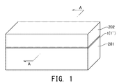
- FIG. 1 is a perspective view showing an example of a use state of the double-coated pressure-sensitive adhesive tape roll of the present invention.
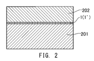
- FIG. 2 is a sectional view taken along the line AA in FIG.
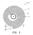
- FIG. 3 is a vertical cross-sectional view showing a double-sided pressure-sensitive adhesive tape roll (unused state) of the present invention.
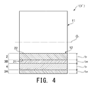
- FIG. 4 is a transverse cross-sectional view (a cross-sectional view taken along line BB in FIG. 3) showing the double-sided pressure-sensitive adhesive tape roll of the present invention.
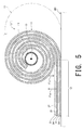
- FIG. 5 is a longitudinal sectional view showing a working state when the double-sided pressure-sensitive adhesive tape roll of the present invention is adhered.
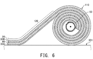
- FIG. 6 is a longitudinal sectional view showing a working state when a conventional double-sided adhesive tape roll is attached.
- FIG. 1 is a perspective view showing an example of a use state of the rolled double-sided adhesive tape of the present invention.
- FIG. 2 is a sectional view taken along the line AA in FIG.
- FIG. 3 is a vertical cross-sectional view showing a double-sided pressure-sensitive adhesive tape roll (unused state) of the present invention.
- FIG. 4 is a transverse cross-sectional view (a cross-sectional view taken along line BB in FIG. 3) showing the double-sided pressure-sensitive adhesive tape roll of the present invention.
- FIG. 5 is a longitudinal sectional view showing a working state when the double-sided pressure-sensitive adhesive tape roll of the present invention is adhered.
- FIG. 6 is a longitudinal sectional view showing a working state when a conventional double-sided adhesive tape roll is attached.
- FIGS. 1 to 5 the upper side in FIGS. 1 to 5 is referred to as “upper (or upper)”, and the lower side is referred to as “lower (or lower)”.
- 3 to 6 the thickness of each layer of the double-sided double-coated pressure-sensitive adhesive tape is emphasized. Further, in FIGS. 3, 5 and 6, a gap is formed in a part of the outer peripheral portion of the core, but it is preferable that this gap is omitted.
- the rolled double-sided adhesive tape 1 is used for joining the first object 201 and the second object 202 in a developed state.
- the use aspect of this double-sided adhesive tape roll 1 is an example, and is not limited to this.
- the wound double-sided pressure-sensitive adhesive tape 1 in an unused state has a double-sided pressure-sensitive adhesive tape 1 ′, which is a double-sided pressure-sensitive adhesive tape, wound in multiple rolls around a core 5.
- This double-sided pressure-sensitive adhesive tape roll 1 (double-sided pressure-sensitive adhesive tape 1 ′) includes a first pressure-sensitive adhesive layer 3A, a support 4, a second pressure-sensitive adhesive layer 3B, and a release liner 2. It is composed of a laminate that is laminated in order.
- the first pressure-sensitive adhesive layer 3 ⁇ / b> A is placed on the core 5 (rolling center O 1 ) of the double-sided pressure-sensitive adhesive tape roll 1 in the cross section of the double-sided pressure-sensitive adhesive tape 1 ′. It is multiply wound so as to be positioned on the outermost side.
- the double-sided adhesive tape wound body 1 having such a configuration includes a wound portion 11 in a wound state and a developed portion 12 which is unfolded from the wound portion 11 and extended. Divided.
- the double-sided pressure-sensitive adhesive tape roll 1 double-sided pressure-sensitive adhesive tape 1 ′
- the first pressure-sensitive adhesive layer 3 ⁇ / b> A of the developing portion 12 having an appropriate length can be stuck to the first object 201.
- the developing unit 12 is cut from the winding unit 11.
- the release liner 2 can be peeled from the developing section 12.
- the second pressure-sensitive adhesive layer 3 ⁇ / b> B is exposed in the development part 12.
- the second object 202 can be attached to the second adhesive layer 3B. Thereby, the first object 201 and the second object 202 are joined.
- the support 4 is made of a flexible, long band-shaped member.
- the support 4 has a function as a core material of the double-sided pressure-sensitive adhesive tape 1 ', and also has a function as a support for supporting the first pressure-sensitive adhesive layer 3A and the second pressure-sensitive adhesive layer 3B.
- the support 4 is made of, for example, paper, nonwoven fabric, cloth, plastic film, or foam.
- the double-sided pressure-sensitive adhesive tape 1 ′ (developing portion 12) has flexibility, and thus can conform to the shape of the target object (the first target object 201 or the second target object 202).
- the thickness t 4 of the support 4 is not particularly limited, but is 50 ⁇ m or more and 350 ⁇ m or less for paper, nonwoven fabric or cloth, 6 ⁇ m or more and 250 ⁇ m or less for plastic film, and 100 ⁇ m or more and 3000 ⁇ m for foam. The following is preferred.
- the support 4 may have a roll-shaped winding habit in advance.
- a first pressure-sensitive adhesive layer 3A is formed over the entire surface, and on the other surface of the support 4 (the surface on the core 5 side), The second pressure-sensitive adhesive layer 3B is formed over the entirety.
- the first pressure-sensitive adhesive layer 3A is a layer that is adhered to the first object 201.
- the second pressure-sensitive adhesive layer 3B is a layer that is adhered to the second object 202.
- the pressure-sensitive adhesive constituting the first pressure-sensitive adhesive layer 3A and the second pressure-sensitive adhesive layer 3B may be any of acrylic, rubber, silicone, urethane and the like, but acrylic is preferable in terms of excellent adhesiveness.
- the acrylic pressure-sensitive adhesive composition includes an acrylic polymer (base), a crosslinking agent, and a tackifier (tackifier).
- the main agent is configured to include a main monomer that imparts tackiness and a monomer that imparts cohesive strength.
- Acrylic monomers can be used as the main monomer.
- the acrylic monomer for example, butyl (meth) acrylate, 2-ethylhexyl (meth) acrylate, octyl (meth) acrylate, dodecyl (meth) acrylate and the like are preferable, and butyl acrylate and 2-ethylhexyl acrylate are more preferable.
- Examples of the monomer that imparts cohesion include a monomer that has cohesion itself and a monomer that has crosslinkability.
- Examples of the monomer having cohesion itself include methyl (meth) acrylate, vinyl acetate, styrene and the like.
- crosslinkable monomer examples include monomers having a crosslinkable functional group such as a hydroxyl group, a carboxyl group, and an amide group.
- Examples of the monomer having a hydroxyl group include 2-hydroxyethyl (meth) acrylate, 3-hydroxypropyl (meth) acrylate, and 4-hydroxybutyl (meth) acrylate.
- Examples of the monomer having a carboxyl group include acrylic acid and methacrylic acid.
- Examples of the monomer having an amide group include acrylamide and methacrylamide.
- These monomers that impart cohesive strength to the main agent may be used alone or in a combination of two or more.
- the main agent can be adjusted to one having a suitable cohesive force.
- Crosslinking agent examples include an isocyanate-based crosslinking agent, an epoxy-based crosslinking agent, and an aziridine-based crosslinking agent. Isocyanate-based crosslinking agents are preferred from the viewpoint of increasing the cohesive force to obtain a pressure-sensitive adhesive composition with improved pressure-sensitive adhesive strength.
- isocyanate-based crosslinking agent examples include adduct, biuret, and nurate of polyvalent isocyanate compounds such as tolylene diisocyanate, xylylene diisocyanate, diphenylmethane diisocyanate, and hexamethylene diisocyanate.
- the content of the cross-linking agent is appropriately adjusted depending on the number of cross-linkable functional groups of the main agent (acrylic polymer) contained in the pressure-sensitive adhesive composition, and is 0.01 to 10 parts by mass based on 100 parts by mass of the main agent. , Preferably 0.03 to 7 parts by mass.
- the tackifier supplementarily improves the adhesive force of the acrylic polymer (base agent).
- the adherend that is, the first object 201 and the second object 202 include a polyolefin such as polyethylene or polypropylene
- the polarity of the polyolefin is relatively low. It can be difficult to make it work.
- a pressure-sensitive adhesive composition containing a tackifier together with an acrylic polymer a good adhesive strength can be exhibited even for such a low-polarity adherend.
- Tackifire includes, for example, rosin-based resins, terpene-based resins, petroleum-derived resins, and styrene-based resins.
- rosin resin examples include a rosin resin, a rosin ester resin, a polymerized rosin ester resin, an acid-modified polymerized rosin ester resin, a rosin-modified phenol resin, and hydrides thereof.
- terpene resin examples include terpene resins, terpene phenol resins, aromatic modified terpene resins, and hydrides thereof.
- Examples of the petroleum-derived resin include a C5 petroleum resin, a C9 petroleum resin, a C5-C9 copolymer petroleum resin, and hydrides thereof.
- Styrene resins include polystyrene resins, ⁇ -methylstyrene resins, and hydrides thereof.
- tackifiers may be used alone or in combination of two or more having different softening points and structures.
- the tackifier preferably has a softening point of 100 ° C. or more and 160 ° C. or less, and more preferably 110 ° C. or more and 130 ° C. or less.
- the softening point of the tackifier is within the above range, the adhesive strength of the adhesive composition can be further improved.
- the “softening point” of the tackifier means a value measured according to JIS K2207: 1996.
- the content ratio of the plurality of tackifiers is preferably adjusted so that the weighted average of the softening points of the plurality of tackifiers falls within the above range.
- the weight average molecular weight (Mw) of the tackifier is usually less than 20,000, preferably 400 to 10,000, more preferably 500 to 8,000.
- the content of the tackifier is preferably 20 parts by mass or more and 60 parts by mass or less, more preferably 30 parts by mass or more and 50 parts by mass or less with respect to 100 parts by mass of the main agent.
- the tackifier content is less than the lower limit or more than the upper limit, the effect of improving the adhesive strength is not sufficient.
- the pressure-sensitive adhesive composition may contain additives other than the above-described components, if necessary.
- additives examples include an ultraviolet absorber, an antioxidant, a plasticizer, a filler, and a colorant. Each of these additives may be used alone or in combination of two or more.
- composition of the first pressure-sensitive adhesive layer 3A and the second pressure-sensitive adhesive layer 3B may be the same or different.
- the thickness t 3A of the first pressure-sensitive adhesive layer 3A (see FIG. 4) and the thickness t 3B of the second pressure-sensitive adhesive layer 3B (see FIG. 4) are not particularly limited, but are, for example, not less than 5 ⁇ m and not more than 500 ⁇ m. And more preferably 10 ⁇ m or more and 100 ⁇ m or less. Further, the thickness t 3A and the thickness t 3B may be the same or different.
- the release liner 2 is made of a flexible and long band-shaped member similarly to the support 4, and the first double-sided adhesive tape wound body 1
- the function of preventing the pressure-sensitive adhesive layer 3A and the second pressure-sensitive adhesive layer 3B from adhering to each other, and the function of transporting the first pressure-sensitive adhesive layer 3A, the support 4 and the second pressure-sensitive adhesive layer 3B to an object to be bonded. Have.
- the surface 21 (outer surface) of the release liner 2 in the winding part 11 is in close contact with (adhered to) the second pressure-sensitive adhesive layer 3 ⁇ / b> B, and is opposite to the surface 21.
- Surface 22 (the inner surface) is in close contact with (adhered to) the first pressure-sensitive adhesive layer 3A.
- the release liner 2 has a surface 21 having releasability from the second adhesive layer 3B, and a surface 22 having releasability from the first adhesive layer 3A.
- the peel force F 3B from the second adhesive layer 3B of the release liner 2 is preferably greater than the peel force F 3A from the first pressure-sensitive adhesive layer 3A of release liner 2 (see FIG. 5).
- the peeling force F 3A is a force required for peeling the release liner 2 from the first pressure-sensitive adhesive layer 3A
- the peeling force F 3B is a force for peeling the release liner 2 from the second pressure-sensitive adhesive layer 3B. It is the power that is sometimes needed.
- the release liner 2 is in contact with both the first pressure-sensitive adhesive layer 3A and the second pressure-sensitive adhesive layer 3B.
- the release liner 2 Is peeled from the first pressure-sensitive adhesive layer 3A of the winding part 11 before the second pressure-sensitive adhesive layer 3B when the development part 12 is deployed (see FIG. 5). Thereafter, in the developing section 12, the release liner 2 can be released from the second pressure-sensitive adhesive layer 3B.
- the second object 202 can be attached to the second adhesive layer 3B.
- the peeling force F 3B is preferably 1.1 to 500 times, more preferably 1.1 to 10 times the peeling force F 3A .
- the peeling force F 3A is preferably from 10 to 2000 mN / 50 mm, and more preferably from 10 to 500 mN / 50 mm. Further, the peeling force F 3B is preferably from 200 to 5000 mN / 50 mm, and more preferably from 200 to 1000 mN / 50 mm. With such a numerical range, the release liner 2 can be easily and smoothly peeled.
- the peeling force F 3A is measured at a test temperature of 23 ° C. and a rewinding speed of 300 mm / min based on “low-speed rewinding force” specified in JIS Z0237: 2009.
- the peeling force F 3B is measured at a test temperature of 23 ° C. and a peeling speed of 300 mm / min based on “Testing method for peeling a release liner at 180 ° to an adhesive surface of a tape” specified in JIS Z0237: 2009. Is done.
- the ball tack of the first pressure-sensitive adhesive layer 3A is preferably 2 to 32, more preferably 10 to 20. If it is less than the lower limit value, it cannot be temporarily fixed to the first object 201, and if it exceeds the upper limit value, it is inferior in workability because it is adhered to a finger or a hand.
- “Ball tack” is a numerical value obtained based on an inclined ball tack defined in JIS Z0237: 2009, based on an inclination angle of 30 degrees.
- the adhesive force of the first adhesive layer 3A is preferably from 2 to 50 N / 25 mm, more preferably from 5 to 40 N / 25 mm, even more preferably from 10 to 30 N / 25 mm. If the adhesive strength of the first adhesive layer 3A is less than the lower limit, since becomes smaller than the peeling force F 3A from the first pressure-sensitive adhesive layer 3A of release liner 2, when attached to the first object 201 At the same time, the workability of developing the double-sided pressure-sensitive adhesive tape 1 ′ while rolling the winding portion 11 is poor. Further, when the adhesive force of the first adhesive layer 3A is more than the upper limit, the adhesive force to the first object 201 is too high, so that alignment becomes difficult.
- the adhesive strength of the first pressure-sensitive adhesive layer 3A is based on the “test method of peeling a tape to a stainless steel test plate at 180 °” specified in JIS Z0237: 2009, at a test temperature of 23 ° C and within 1 minute after pressure bonding. , Measured at a peeling speed of 300 mm / min.
- the release liner 2 is not particularly limited, and a known release liner used as a release liner of a double-sided pressure-sensitive adhesive tape (double-sided pressure-sensitive adhesive tape 1) can be appropriately selected and used.
- a paper or a plastic film that has been subjected to a process of peeling the pressure-sensitive adhesive layer on both sides is used as the release liner 2.
- Examples of the paper include high quality paper, glassine paper, and kraft paper.
- Examples of the plastic film include polyethylene terephthalate, polypropylene, and polyethylene.
- peeling treatment examples include applying silicone, fluorine, fluorosilicone, alkyd, etc., but silicone is preferred because the peeling force can be easily adjusted.
- the release treatment is performed so that the release force of the surface 21 of the release liner 2 that is in contact with the first pressure-sensitive adhesive layer 3A is larger than the surface 22 of the release liner 2 that is in contact with the second pressure-sensitive adhesive layer 3B.
- a method of adjusting the amount of the silicone resin and the like can be mentioned.
- the thickness t 2 (see FIG. 4) of the release liner 2 is not particularly limited, but is preferably from 10 ⁇ m to 150 ⁇ m, and more preferably from 20 ⁇ m to 130 ⁇ m.
- the material of the core 5 includes paper, vinyl chloride, polypropylene, acrylonitrile-butadiene-styrene copolymer and the like. Among these, paper is preferred because it can be easily cut to an arbitrary width.
- the inner diameter of the core 5 is 25, 30, 35, 76 mm, or the like. Among these, 76 mm having a large inner diameter is preferable from the viewpoint of sticking workability.
- the width of the double-sided adhesive tape 1 is preferably 1 mm or more and 100 mm or less. If it exceeds 100 mm, it will be easy to adhere to hands, fingers and objects to be stuck, and workability will be reduced.
- a release liner 2 having both sides of the release liner 2 subjected to a release treatment is prepared.
- the surface of the release liner 2 that is in contact with the second pressure-sensitive adhesive layer 3B is subjected to a release treatment so that the release force is greater than that of the surface 22 that is in contact with the first pressure-sensitive adhesive layer 3A.
- a second pressure-sensitive adhesive layer 3B, a support 4 and a first pressure-sensitive adhesive layer 3A are formed in this order. Thereby, the double-sided adhesive tape 1 'is obtained.
- the double-sided adhesive tape 1 ′ is gradually wound in a roll shape from one end side such that the surface 22 of the release liner 2 faces the core 5.
- the first pressure-sensitive adhesive layer 3A in cross-section of the double-sided adhesive tape 1 ' is outermost with respect to the winding center O 1 of the double-sided pressure-sensitive adhesive tape wound body 1, it will wound multiply.
- a double-sided pressure-sensitive adhesive tape wound body 1 in which the double-sided pressure-sensitive adhesive tape 1 'is wound is obtained.
- the first pressure-sensitive adhesive layer 3A has the core 5 ( It is multiply wound so as to be positioned on the outermost side with respect to the winding center O 1 ).
- this state is referred to as “the first pressure-sensitive adhesive layer outside arrangement state”.
- the first pressure-sensitive adhesive layer 3A can be brought closer to the first object 201 at the time of sticking, the alignment of the first pressure-sensitive adhesive layer 3A with respect to the first object 201 can be easily performed. Thereby, the first pressure-sensitive adhesive layer 3A can be accurately adhered to the first object 201.
- the vicinity of the winding core 5 (winding center O 1 ) of the winding portion 11 is grasped by hand, and the extending direction of the unfolding portion 12 is adjusted so that the winding portion 11 is aligned with the first object 201. It rotates in the opposite direction, that is, toward the right side in FIG. Thereby, the development part 12 can be formed longer.
- the winding part 11 can be rotated while pressing the winding part 11 against the first object 201 from above in FIG. By this pressing, fixing (press-bonding) of the deployed portion 12 to the first object 201 can be performed.
- the unfolded portion 12 is rotated in the opposite direction, that is, toward the left side in FIG. 11, so that the length of the unfolded portion 12 can be adjusted.
- the developing section 12 is cut at an appropriate place.
- the developing unit 12 double-sided adhesive tape 1 ′
- the developing unit 12 is attached to the first object 201.
- the second object 202 is attached to the second pressure-sensitive adhesive layer 3B. Thereby, the first object 201 and the second object 202 are joined.
- the first target object 201 and the second target object 202 are firmly joined via the double-sided adhesive tape 1 ′, that is, are permanently fixed (finally pressed).
- the first pressure-sensitive adhesive layer 3A is first aligned with the first object 201 while being positioned.
- the winding portion 11 is rotated as it is as described above, the operation of attaching the double-sided adhesive tape wound body 1 to the first object 201 can be performed easily and quickly. Thereby, the operability at the time of sticking and using the double-sided adhesive tape roll 1 is excellent, and the double-sided adhesive tape roll 1 is easy to use.
- the double-sided pressure-sensitive adhesive tape 1 ′ During application of the double-sided pressure-sensitive adhesive tape 1 ′, application of tension to the double-sided pressure-sensitive adhesive tape 1 ′ can be suppressed as much as possible. Thereby, the double-sided adhesive tape 1 ′ is suppressed or prevented from contracting after the first object 201 and the second object 202 are joined. Thereby, it is possible to prevent the double-sided adhesive tape 1 ′ from peeling off from the first object 201 and the second object 202, so that the joining state between the first object 201 and the second object 202 can be maintained for a long time. Can be maintained.
- the double-sided pressure-sensitive adhesive tape roll of the present invention has been described with reference to the illustrated embodiment, the present invention is not limited to this. It can be replaced with any configuration that can be exhibited. Also, an arbitrary component may be added.
- the rolled double-sided pressure-sensitive adhesive tape of the present invention has a first pressure-sensitive adhesive layer, a support, a second pressure-sensitive adhesive layer, and a release liner.
Landscapes
- Chemical & Material Sciences (AREA)
- Organic Chemistry (AREA)
- Adhesive Tapes (AREA)
Abstract
両面粘着テープ巻回体は、第1粘着剤層と、支持体と、第2粘着剤層と、剥離ライナーとを有し、これらがこの順で積層された両面粘着テープが巻心に対してロール状に多重巻回されたものである。この両面粘着テープ巻回体は、両面粘着テープの横断面において第1粘着剤層が両面粘着テープ巻回体の巻心に対して最も外側に位置するように、多重巻回されている。また、両面粘着テープ巻回体では、剥離ライナーの第2粘着剤層からの剥離力が、剥離ライナーの第1粘着剤層からの剥離力よりも大きいのが好ましい。
Description
本発明は、両面粘着テープ巻回体に関する。
従来の両面粘着テープとしては、例えば、支持体と、支持体の両面にそれぞれ支持された第1粘着剤層および第2粘着剤層とを有する両面粘着テープが知られている(例えば、特許文献1、特許文献2参照)。特許文献1、特許文献2に記載の両面粘着テープは、図6に示すように、未使用状態では、剥離ライナー20ごと巻回されており、その横断面における第1粘着剤層30A、支持体40、第2粘着剤層30B、剥離ライナー20の中で、剥離ライナー20が、巻心50から最も外側に位置している。
このような構成の両面粘着テープを貼着する際には、まず、巻回状態にある両面粘着テープの一部(一端部)を巻き戻し(unwind)、この巻き戻された部分(以下「展開部120」と言う)を貼着対象物301に貼着する。このとき、展開部120は、図6中の右斜め上方から貼着対象物301に対して延びているため、貼着対象物301との距離が比較的大きく(遠く)なる。そして、その距離の程度によっては、展開部120と貼着対象物301との位置合わせを行いづらくなる場合がある。
また、前記貼着対象物301との距離は、巻回状態にある両面粘着テープの直径に比例して大きくなる。そのため、展開部120と貼着対象物301との位置合わせがさらに難しくなる傾向にある。また、巻回されている部分(以下「巻回部110」と言う)が位置合わせの邪魔になる。
また、この位置合わせ時には、巻回部110から貼着対象物301までの距離が長いため、展開部120に張力を付与することとなる。そのため、展開部120は、貼着対象物301に貼着された後に収縮することとなり、その収縮の程度によっては、貼着対象物301から剥がれる場合もある。
本発明の目的は、両面粘着テープ巻回体を貼着して使用する際の操作性に優れる両面粘着テープ巻回体を提供することにある。
このような目的は、下記(1)~(4)の本発明により達成される。
(1) 第1粘着剤層と、支持体と、第2粘着剤層と、剥離ライナーとを有し、これらがこの順で積層された両面粘着テープが巻心に対してロール状に多重巻回された両面粘着テープ巻回体であって、
前記両面粘着テープの横断面において前記第1粘着剤層が前記両面粘着テープ巻回体の前記巻心に対して最も外側に位置するように、多重巻回されていることを特徴とする両面粘着テープ巻回体。
(1) 第1粘着剤層と、支持体と、第2粘着剤層と、剥離ライナーとを有し、これらがこの順で積層された両面粘着テープが巻心に対してロール状に多重巻回された両面粘着テープ巻回体であって、
前記両面粘着テープの横断面において前記第1粘着剤層が前記両面粘着テープ巻回体の前記巻心に対して最も外側に位置するように、多重巻回されていることを特徴とする両面粘着テープ巻回体。
(2) 前記剥離ライナーの前記第2粘着剤層からの剥離力が、前記剥離ライナーの前記第1粘着剤層からの剥離力よりも大きい上記(1)に記載の両面粘着テープ巻回体。
(3) 前記剥離ライナーの前記第1粘着剤層からの剥離力が10~2000mN/50mmであり、かつ、前記剥離ライナーの前記第2粘着剤層からの剥離力が200~5000mN/50mmである上記(1)または(2)に記載の両面粘着テープ巻回体。
(4) 前記第1粘着剤層のボールタックが2~32である上記(1)ないし(3)のいずれかに記載の両面粘着テープ巻回体。
本発明によれば、両面粘着テープ巻回体を貼着して使用する際の操作性に優れる両面粘着テープ巻回体を提供することができる。
以下、本発明の両面粘着テープ巻回体を添付図面に示す好適な実施形態に基づいて詳細に説明する。
図1は、本発明の両面粘着テープ巻回体の使用状態の一例を示す斜視図である。図2は、図1中のA-A線断面図である。図3は、本発明の両面粘着テープ巻回体(未使用状態)を示す縦断面図である。図4は、本発明の両面粘着テープ巻回体を示す横断面図(図3中のB-B線断面図)である。図5は、本発明の両面粘着テープ巻回体を貼着する際の作業状態を示す縦断面図である。図6は、従来の両面粘着テープ巻回体を貼着する際の作業状態を示す縦断面図である。なお、以下では、説明の都合上、図1~図5中の上側を「上(または上方)」、下側を「下(または下方)」と言う。また、図3~図6では、両面粘着テープ巻回体の各層の厚さを強調して描いている。また、図3、図5および図6では、巻心の外周部の一部に隙間が生じているが、この隙間は、省略されているのが好ましい。
図1、図2に示すように、本実施形態では、両面粘着テープ巻回体1は、展開した状態で、第1対象物201と第2対象物202との接合に用いられている。なお、この両面粘着テープ巻回体1の使用態様は、一例であり、これに限定されない。
図3に示すように、未使用状態の両面粘着テープ巻回体1は、両面粘着テープである両面粘着テープ1’が巻心5に対してロール状に多重に巻回された巻回状態となっている。この両面粘着テープ巻回体1(両面粘着テープ1’)は、第1粘着剤層3Aと、支持体4と、第2粘着剤層3Bと、剥離ライナー2と、を有し、これらがこの順で積層された積層体で構成されている。そして、未使用状態の両面粘着テープ巻回体1は、両面粘着テープ1’の横断面において第1粘着剤層3Aが両面粘着テープ巻回体1の巻心5(巻回中心O1)に対して最も外側に位置するように、多重巻回されている。
このような構成の両面粘着テープ巻回体1は、図5に示すように、巻回状態となっている巻回部11と、巻回部11から展開されて伸ばされた展開部12とに分けられる。両面粘着テープ巻回体1(両面粘着テープ1’)は、適当な長さとなった展開部12の第1粘着剤層3Aを第1対象物201に貼着することができる。その後、展開部12を巻回部11から切断する。そして、展開部12から剥離ライナー2を剥離することができる。これにより、展開部12には、第2粘着剤層3Bが露出する。第2粘着剤層3Bには、第2対象物202を貼着することができる。これにより、第1対象物201と第2対象物202とが接合される。
以下、両面粘着テープ巻回体1(両面粘着テープ1’)を構成する各部(各層)について説明する。
支持体4は、可撓性を有し、長尺な帯状をなす部材で構成されている。この支持体4は、両面粘着テープ1’の芯材としての機能を有するとともに、第1粘着剤層3Aと第2粘着剤層3Bとを支持する支持体としての機能も有している。
支持体4は、例えば、紙、不織布、布、プラスチックフィルム、発泡体で構成されている。これにより、両面粘着テープ1’(展開部12)は、可撓性を有し、よって、対象物(第1対象物201や第2対象物202)の形状に沿わせることができる。
支持体4の厚さt4(図4参照)は、特に限定されないが、紙、不織布、布としては、50μm以上350μm以下、プラスチックフィルムとしては、6μm以上250μm以下、発泡体としては100μm以上3000μm以下であることが好ましい。
また、支持体4は、予めロール状の巻き癖がついていてもよい。
支持体4の一方の面(巻心5と反対側の面)には、その全体にわたって第1粘着剤層3Aが形成され、支持体4の他方の面(巻心5側の面)には、その全体にわたって第2粘着剤層3Bが形成されている。
支持体4の一方の面(巻心5と反対側の面)には、その全体にわたって第1粘着剤層3Aが形成され、支持体4の他方の面(巻心5側の面)には、その全体にわたって第2粘着剤層3Bが形成されている。
第1粘着剤層3Aは、第1対象物201に対して貼着される層である。
第2粘着剤層3Bは、第2対象物202に対して貼着される層である。
第2粘着剤層3Bは、第2対象物202に対して貼着される層である。
第1粘着剤層3Aおよび第2粘着剤層3Bを組成する粘着剤は、アクリル系、ゴム系、シリコーン系、ウレタン系等のいずれでもよいが、粘着性に優れる点でアクリル系が好ましい。アクリル系粘着剤組成物は、アクリル系ポリマー(主剤)、架橋剤およびタッキファイヤー(粘着付与剤)を含んで構成される。
(主剤)
主剤は、粘着性を付与する主モノマーと、凝集力を付与するモノマーとを含んで構成される。
主剤は、粘着性を付与する主モノマーと、凝集力を付与するモノマーとを含んで構成される。
主モノマーとしては、アクリル系モノマーが挙げられる。アクリル系モノマーとしては、例えば、ブチル(メタ)アクリレート、2-エチルへキシル(メタ)アクリレート、オクチル(メタ)アクリレート、ドデシル(メタ)アクリレート等が好ましく、ブチルアクリレート、2-エチルヘキシルアクリレートがより好ましい。
凝集力を付与するモノマーとしては、例えば、それ自体が凝集力を有するモノマー、架橋性を有するモノマーが挙げられる。
それ自体が凝集力を有するモノマーとしては、例えば、メチル(メタ)アクリレート、酢酸ビニル、スチレン等が挙げられる。
架橋性を有するモノマーとしては、水酸基、カルボキシル基、アミド基等の架橋性官能基を有するモノマーが挙げられる。
水酸基を有するモノマーとしては、例えば、2-ヒドロキシエチル(メタ)アクリレート、3-ヒドロキシプロピル(メタ)アクリレート、4-ヒドロキシブチル(メタ)アクリレート等が挙げられる。
カルボキシル基を有するモノマーとしては、例えば、アクリル酸、メタクリル酸が挙げられる。
アミド基を有するモノマーとしては、例えば、アクリルアミド、メタクリルアミドが挙げられる。
これらの主剤に凝集力を付与するモノマーは、1種を単独で用いてもよいし、2種以上を組み合わせて用いてもよい。特に、水酸基を有するモノマーとカルボキシル基を有するモノマーとを併用することにより、主剤を好適な凝集力を有するものに調節することができる。
(架橋剤)
架橋剤としては、例えば、イソシアネート系架橋剤、エポキシ系架橋剤、アジリジン系架橋剤、が挙げられる。凝集力を高めて粘着力をより向上させた粘着剤組成物とする観点から、イソシアネート系架橋剤が好ましい。
架橋剤としては、例えば、イソシアネート系架橋剤、エポキシ系架橋剤、アジリジン系架橋剤、が挙げられる。凝集力を高めて粘着力をより向上させた粘着剤組成物とする観点から、イソシアネート系架橋剤が好ましい。
イソシアネート系架橋剤としては、例えば、トリレンジイソシアネート、キシリレンジイソシアネート、ジフェニルメタンジイソシアネート、ヘキサメチレンジイソシアネート等の多価イソシアネート化合物の、アダクト体、ビウレット体、ヌレート体等が挙げられる。
架橋剤の含有量は、粘着剤組成物に含まれる主剤(アクリル系ポリマー)が有する架橋性官能基の数により適宜調整されるが、主剤の100質量部に対して、0.01~10質量部であることが好ましく、0.03~7質量部であることがより好ましい。
(タッキファイヤー)
タッキファイヤー(粘着付与剤)は、アクリル系ポリマー(主剤)が有する粘着力を補助的に向上させる。
タッキファイヤー(粘着付与剤)は、アクリル系ポリマー(主剤)が有する粘着力を補助的に向上させる。
特に、被着体、すなわち、第1対象物201と第2対象物202とがポリエチレンやポリプロピレン等のポリオレフィンを含む場合、ポリオレフィンの極性が比較的低いため、アクリル系ポリマーでは、高い粘着力で接合させることが難しい場合がある。しかしながら、アクリル系ポリマーと共にタッキファイヤーを含有した粘着剤組成物とすることで、このような極性の低い被着体に対しても、良好な粘着力を発現させることができる。
タッキファイヤーとしては、例えば、ロジン系樹脂、テルペン系樹脂、石油由来樹脂、スチレン系樹脂が挙げられる。
ロジン系樹脂としては、例えば、ロジン樹脂、ロジンエステル樹脂、重合ロジンエステル樹脂、酸変性重合ロジンエステル樹脂、ロジン変性フェノール樹脂およびこれらの水素化物等が挙げられる。
テルペン系樹脂としては、例えば、テルペン樹脂、テルペンフェノール樹脂、芳香族変性テルペン樹脂およびこれらの水素化物等が挙げられる。
石油由来樹脂としては、例えば、C5系石油樹脂、C9系石油樹脂、C5-C9共重合系石油樹脂およびこれらの水素化物等が挙げられる。
スチレン系樹脂としては、ポリスチレン樹脂、α-メチルスチレン樹脂およびこれらの水素化物等が挙げられる。
なお、これらのタッキファイヤーは、単独でまたは軟化点や構造が異なる2種以上を組み合わせて用いてもよい。
タッキファイヤーは、軟化点が100℃以上160℃以下のものであることが好ましく、110℃以上130℃以下のものであることがより好ましい。タッキファイヤーの軟化点が前記範囲であることにより、粘着剤組成物の粘着力をより向上させることができる。
なお、本明細書において、タッキファイヤーの「軟化点」は、JISK2207:1996に準拠して測定した値を意味する。
また、2種以上のタッキファイヤーを用いる場合、それら複数のタッキファイヤーの軟化点の加重平均が、前記範囲に属するように、複数のタッキファイヤーの含有量比が調整されることが好ましい。
タッキファイヤーの質量平均分子量(Mw)は、通常20000未満であるが、400~10000が好ましく、500~8000がより好ましい。
タッキファイヤーの含有量は、主剤100質量部に対して20質量部以上60質量部以下であることが好ましく、30質量部以上50質量部以下であることがより好ましい。
タッキファイヤーの含有量が前記下限値未満または前記上限値超では粘着力を向上させる効果が十分ではなくなる。
(その他の成分)
粘着剤組成物は、必要に応じて、上述した成分以外の添加剤を含有してもよい。
粘着剤組成物は、必要に応じて、上述した成分以外の添加剤を含有してもよい。
添加剤としては、例えば、紫外線吸収剤、酸化防止剤、可塑剤、充填剤、着色剤等が挙げられる。これらの各添加剤は、単独で用いてもよく、2種以上を併用してもよい。
なお、第1粘着剤層3Aと、第2粘着剤層3Bとは、組成が同じであってもよいし、異なっていてもよい。
また、第1粘着剤層3Aの厚さt3A(図4参照)と、第2粘着剤層3Bの厚さt3B(図4参照)とは、特に限定されないが、例えば、5μm以上500μm以下であることが好ましく、10μm以上100μm以下であることがより好ましい。また、厚さt3Aと厚さt3Bとは、同じであってもよいし、異なっていてもよい。
図3に示すように、剥離ライナー2は、支持体4と同様に、可撓性を有し、長尺な帯状をなす部材で構成されており、両面粘着テープ巻回体1において、第1粘着剤層3Aと第2粘着剤層3Bとが接着してしまうことを防ぐ機能、および第1粘着剤層3A、支持体4および第2粘着剤層3Bを貼着対象物まで搬送する機能を有している。
図5に示すように、剥離ライナー2は、巻回部11では、面21(外側の面)が第2粘着剤層3Bに密着しており(貼着しており)、面21と反対側の面22(内側の面)が第1粘着剤層3Aに密着している(貼着している)。
また、剥離ライナー2は、面21が第2粘着剤層3Bに対して剥離性を有し、面22が第1粘着剤層3Aに対して剥離性を有している。
そして、剥離ライナー2の第2粘着剤層3Bからの剥離力F3Bは、剥離ライナー2の第1粘着剤層3Aからの剥離力F3Aよりも大きいのが好ましい(図5参照)。ここで、剥離力F3Aとは、第1粘着剤層3Aから剥離ライナー2を剥離するときに要する力であり、剥離力F3Bとは、第2粘着剤層3Bから剥離ライナー2を剥離するときに要する力である。巻回部11において、剥離ライナー2は、第1粘着剤層3Aおよび第2粘着剤層3Bの両方に接しているが、剥離力F3Bが剥離力F3Aよりも大きいことにより、剥離ライナー2は、展開部12の展開時に、第2粘着剤層3Bよりも先に、巻回部11の第1粘着剤層3Aから剥離する(図5参照)。その後、展開部12では、剥離ライナー2を第2粘着剤層3Bから剥離させることができる。この第2粘着剤層3Bには、第2対象物202を貼着させることができる。
なお、剥離力F3Bは、剥離力F3Aの1.1倍以上500倍以下であるのが好ましく、1.1倍以上10倍以下であるのがより好ましい。
また、剥離力F3Aは、10~2000mN/50mmであるのが好ましく、10~500mN/50mmであるのがより好ましい。また、剥離力F3Bは、200~5000mN/50mmであるのが好ましく、200~1000mN/50mmであるのがより好ましい。このような数値範囲により、剥離ライナー2を容易かつ円滑に剥離することができる。
剥離力F3Aは、JIS Z0237:2009に規定される「低速巻戻し力」に基づいて、試験温度23℃、巻戻し速度300mm/分で測定される。
剥離力F3Bは、JIS Z0237:2009に規定される「剥離ライナーをテープの粘着面に対して180°に引きはがす試験方法」に基づいて、試験温度23℃、引きはがし速度300mm/分で測定される。
また、第1粘着剤層3Aのボールタックは、2~32であるのが好ましく、10~20であるのがより好ましい。下限値未満では、第1対象物201に対して仮固定することができず、上限値超では、指や手に接着するため作業性に劣る。「ボールタック」とは、JIS Z0237:2009に規定された傾斜式ボールタックに基づいて、傾斜角30度により求められる数値である。
第1粘着剤層3Aの粘着力は、2~50N/25mmであることが好ましく、5~40N/25mmであることがより好ましく、10~30N/25mmであることがさらに好ましい。第1粘着剤層3Aの粘着力が下限値未満である場合、剥離ライナー2の第1粘着剤層3Aからの剥離力F3Aよりも小さくなってしまうため、第1対象物201に貼着すると同時に巻回部11を転回しながら両面粘着テープ1’を展開する作業性に劣る。また、第1粘着剤層3Aの粘着力が上限値超である場合、第1対象物201への粘着力が高すぎて、位置合わせが困難になる。
第1粘着剤層3Aの粘着力は、JIS Z0237:2009に規定される「テープをステンレス試験板に対して180°に引きはがす試験方法」に基づいて、試験温度23℃、圧着後1分以内、引きはがし速度300mm/分で測定される。
剥離ライナー2としては、特に限定されず、両面粘着テープ(両面粘着テープ1)の剥離ライナーとして用いられている、公知の剥離ライナーを適宜選択して用いることができる。一般的には、剥離ライナー2としては、紙またはプラスチックフィルムの両面に、粘着剤層が剥離する処理がされたものを用いる。
紙としては、上質紙、グラシン紙、クラフト紙等が挙げられる。プラスチックフィルムとしては、ポリエチレンテレフタレート、ポリプロピレン、ポリエチレン等が挙げられる。
剥離処理としては、シリコーン、フッ素、フルオロシリコーン、アルキッド等を塗布すること等が挙げられるが、剥離力を調整しやすい点でシリコーンが好ましい。
剥離ライナー2の第1粘着剤層3Aに接する側の面22よりも、第2粘着剤層3Bに接する側の面21の剥離力が大きくなるように剥離処理をすることが好ましい。シリコーンにより剥離力の大小を調整するには、シリコーンレジンの量を調整する方法等が挙げられる。
剥離ライナー2の厚さt2(図4参照)は、特に限定されないが、10μm以上150μm以下であることが好ましく、20μm以上130μm以下であることが好ましい。
巻心5の材質は、紙、塩化ビニル、ポリプロピレン、アクリロニトリル-ブタジエン-スチレン共重合体等が挙げられる。これらの中でも、任意の幅に切断しやすい点で紙が好ましい。
巻心5の内径は、25、30、35、76mm等が挙げられる。これらの中でも、貼着作業性の点で、内径が大きい76mmが好ましい。
両面粘着テープ1の幅は、1mm以上100mm以下であることが好ましい。100mmを超えると、手、指および貼着対象物に接着しやすいなるため、作業性が低下する。
次に、両面粘着テープ巻回体1の製造方法の一例について説明する。
まず、剥離ライナー2の両面に剥離処理がされた剥離ライナー2を準備する。剥離ライナー2の第2粘着剤層3Bに接する面21は、第1粘着剤層3Aに接する面22より剥離力が大きくなるように剥離処理をする。
まず、剥離ライナー2の両面に剥離処理がされた剥離ライナー2を準備する。剥離ライナー2の第2粘着剤層3Bに接する面21は、第1粘着剤層3Aに接する面22より剥離力が大きくなるように剥離処理をする。
剥離ライナー2の面21に、第2粘着剤層3B、支持体4、第1粘着剤層3Aの順に形成する。これにより、両面粘着テープ1’が得られる。
次いで、両面粘着テープ1’を、剥離ライナー2の面22が巻心5に対向するように、その一端側から徐々にロール状に巻回していく。このとき、両面粘着テープ1’の横断面において第1粘着剤層3Aが両面粘着テープ巻回体1の巻回中心O1に対して最も外側に位置するように、多重に巻回していく。これにより、両面粘着テープ1’が巻回されてなる両面粘着テープ巻回体1が得られる。
次に、両面粘着テープ巻回体1を貼着する際の貼着作業について、図3、図5を参照しつつ説明する。
前述したように、図3に示す未使用状態の両面粘着テープ巻回体1は、両面粘着テープ1’の横断面において第1粘着剤層3Aが両面粘着テープ巻回体1の巻心5(巻回中心O1)に対して最も外側に位置するように、多重巻回されている。以下、この状態を「第1粘着剤層外側配置状態」と言う。
そして、第1粘着剤層外側配置状態の両面粘着テープ巻回体1(巻回部11)に対し、図5に示すように、巻回中心O1と反対側の端部に所望の量だけ展開部12を形成させる、すなわち、両面粘着テープ巻回体1を巻き戻す(unwind)。展開部12では、第1粘着剤層3Aが既に下側(外側)に露出しており、この第1粘着剤層3Aを第1対象物201に近づけて、そのまま貼着させることができる。また、その貼着の際、第1粘着剤層3Aを第1対象物201に近づけることができるため、第1対象物201に対する第1粘着剤層3Aの位置合わせも容易に行うことができる。これにより、第1粘着剤層3Aを第1対象物201に正確に貼着することができる。
次いで、巻回部11の巻心5(巻回中心O1)付近を手で把持して、巻回部11を、第1対象物201に沿わせるように、展開部12の延在方向と反対方向、すなわち、図5中の右側に向かって回転させていく。これにより、展開部12をさらに長く形成することができる。また、このとき、巻回部11を第1対象物201に、図5中の上側から押し付けつつ、巻回部11を回転させることができる。この押し付けにより、第1対象物201に対する展開部12の固定(圧着)を行なうことができる。
なお、展開部12の長さが過剰となった場合には、巻回部11を前記と反対方向、すなわち、図5中の左側に向かってに回転させることにより、展開部12が巻回部11に巻き付いていき、よって、展開部12の長さを調整することができる。
次いで、展開部12を適当な箇所で切断する。これにより、第1対象物201には、展開部12(両面粘着テープ1’)が貼られる。
次いで、図示は省略するが、展開部12に対して、剥離ライナー2を剥離していく。これにより、展開部12は、第2粘着剤層3Bが上側(外側)に露出した状態となる。
次いで、第2粘着剤層3Bに第2対象物202を貼着する。これにより、第1対象物201と第2対象物202とが接合される。また、第2対象物202を貼着するときには、第2対象物202を第1対象物201に向かって押し付けるのが好ましい。これにより、両面粘着テープ1’を介して、第1対象物201と第2対象物202とが強固に接合される、すなわち、本固定される(本圧着される)。
以上のように、未使用状態の両面粘着テープ巻回体1が第1粘着剤層外側配置状態となっているため、まずは第1粘着剤層3Aを第1対象物201上に位置合わせしつつ、貼り付けて、そのまま巻回部11を前記のように回転させれば、第1対象物201への両面粘着テープ巻回体1の貼着作業を容易かつ迅速に行なうことができる。これにより、両面粘着テープ巻回体1を貼着して使用する際の操作性に優れ、両面粘着テープ巻回体1は、使い勝手がよいものとなっている。
また、両面粘着テープ1’の貼着作業中、当該両面粘着テープ1’に張力が付与されるのをできる限り抑制することができる。これにより、両面粘着テープ1’は、第1対象物201と第2対象物202とを接合した後に収縮するのが抑制または防止される。これにより、両面粘着テープ1’が第1対象物201や第2対象物202から剥がれるのを防止することができ、よって、第1対象物201と第2対象物202との接合状態を長期間維持することができる。
以上、本発明の両面粘着テープ巻回体を図示の実施形態について説明したが、本発明は、これに限定されるものではなく、両面粘着テープ巻回体を構成する各部は、同様の機能を発揮し得る任意の構成のものと置換することができる。また、任意の構成物が付加されていてもよい。
本発明の両面粘着テープ巻回体は、第1粘着剤層と、支持体と、第2粘着剤層と、剥離ライナーとを有し、これらがこの順で積層された両面粘着テープが巻心に対してロール状に多重巻回された両面粘着テープ巻回体であって、前記両面粘着テープの横断面において前記第1粘着剤層が前記両面粘着テープ巻回体の前記巻心に対して最も外側に位置するように、多重巻回されている。そのため、両面粘着テープ巻回体を貼着して使用する際の操作性に優れる。従って、本発明の両面粘着テープ巻回体は、産業上の利用可能性を有する。
1 両面粘着テープ巻回体
1’ 両面粘着テープ
11 巻回部
12 展開部
2 剥離ライナー
21 面
22 面
3A 第1粘着剤層
3B 第2粘着剤層
4 支持体
5 巻心
20 剥離ライナー
30A 第1粘着剤層
30B 第2粘着剤層
40 支持体
50 巻心
110 巻回部
120 展開部
201 第1対象物
202 第2対象物
301 貼着対象物
F3A 剥離力
F3B 剥離力
O1 巻回中心
t2 厚さ
t3A 厚さ
t3B 厚さ
t4 厚さ
1’ 両面粘着テープ
11 巻回部
12 展開部
2 剥離ライナー
21 面
22 面
3A 第1粘着剤層
3B 第2粘着剤層
4 支持体
5 巻心
20 剥離ライナー
30A 第1粘着剤層
30B 第2粘着剤層
40 支持体
50 巻心
110 巻回部
120 展開部
201 第1対象物
202 第2対象物
301 貼着対象物
F3A 剥離力
F3B 剥離力
O1 巻回中心
t2 厚さ
t3A 厚さ
t3B 厚さ
t4 厚さ
Claims (4)
- 第1粘着剤層と、支持体と、第2粘着剤層と、剥離ライナーとを有し、これらがこの順で積層された両面粘着テープが巻心に対してロール状に多重巻回された両面粘着テープ巻回体であって、
前記両面粘着テープの横断面において前記第1粘着剤層が前記両面粘着テープ巻回体の前記巻心に対して最も外側に位置するように、多重巻回されていることを特徴とする両面粘着テープ巻回体。 - 前記剥離ライナーの前記第2粘着剤層からの剥離力が、前記剥離ライナーの前記第1粘着剤層からの剥離力よりも大きい請求項1に記載の両面粘着テープ巻回体。
- 前記剥離ライナーの前記第1粘着剤層からの剥離力が10~2000mN/50mmであり、かつ、前記剥離ライナーの前記第2粘着剤層からの剥離力が200~5000mN/50mmである請求項1または2に記載の両面粘着テープ巻回体。
- 前記第1粘着剤層のボールタックが2~32である請求項1ないし3のいずれか1項に記載の両面粘着テープ巻回体。
Priority Applications (1)
| Application Number | Priority Date | Filing Date | Title |
|---|---|---|---|
| PCT/JP2018/024728 WO2020003472A1 (ja) | 2018-06-28 | 2018-06-28 | 両面粘着テープ巻回体 |
Applications Claiming Priority (1)
| Application Number | Priority Date | Filing Date | Title |
|---|---|---|---|
| PCT/JP2018/024728 WO2020003472A1 (ja) | 2018-06-28 | 2018-06-28 | 両面粘着テープ巻回体 |
Publications (1)
| Publication Number | Publication Date |
|---|---|
| WO2020003472A1 true WO2020003472A1 (ja) | 2020-01-02 |
Family
ID=68986850
Family Applications (1)
| Application Number | Title | Priority Date | Filing Date |
|---|---|---|---|
| PCT/JP2018/024728 Ceased WO2020003472A1 (ja) | 2018-06-28 | 2018-06-28 | 両面粘着テープ巻回体 |
Country Status (1)
| Country | Link |
|---|---|
| WO (1) | WO2020003472A1 (ja) |
Citations (3)
| Publication number | Priority date | Publication date | Assignee | Title |
|---|---|---|---|---|
| JPS6326283U (ja) * | 1986-08-04 | 1988-02-20 | ||
| JPH0464544U (ja) * | 1990-10-05 | 1992-06-03 | ||
| JP2001348538A (ja) * | 2000-06-06 | 2001-12-18 | Sekisui Chem Co Ltd | 研磨材固定用両面粘着テープ |
-
2018
- 2018-06-28 WO PCT/JP2018/024728 patent/WO2020003472A1/ja not_active Ceased
Patent Citations (3)
| Publication number | Priority date | Publication date | Assignee | Title |
|---|---|---|---|---|
| JPS6326283U (ja) * | 1986-08-04 | 1988-02-20 | ||
| JPH0464544U (ja) * | 1990-10-05 | 1992-06-03 | ||
| JP2001348538A (ja) * | 2000-06-06 | 2001-12-18 | Sekisui Chem Co Ltd | 研磨材固定用両面粘着テープ |
Similar Documents
| Publication | Publication Date | Title |
|---|---|---|
| JP5486503B2 (ja) | フィルム剥離方法、光学フィルムの製造方法、フィルム剥離機構及び光学フィルム製造装置 | |
| JP6679239B2 (ja) | 粘着シート | |
| JP6747784B2 (ja) | 携帯型電子機器用粘着シート | |
| JP4912635B2 (ja) | 貼着部材および光学部品の貼着方法 | |
| JP5740124B2 (ja) | 両面粘着テープ及びタッチパネル付き表示装置 | |
| JP5637792B2 (ja) | 両面粘着テープ及びタッチパネル付き表示装置 | |
| TW201623509A (zh) | 雙面黏貼膠帶、物品及分離方法 | |
| JP6734663B2 (ja) | 手切れ性両面粘着テープ | |
| CN106232756A (zh) | 层叠片 | |
| JP6718142B2 (ja) | 物品の製造方法 | |
| JP6705105B2 (ja) | タイヤ用粘着シート | |
| JP2017071730A (ja) | 粘着シート | |
| JP2015147396A (ja) | 粘着剤付き化粧シート | |
| JP2002121503A (ja) | 床材固定用両面粘着テープ | |
| JP2008106242A (ja) | 易剥離性粘着テープ及びその製造方法 | |
| JP2020183502A (ja) | 粘着フィルム | |
| JP2010076178A (ja) | 保護フィルム | |
| JP5884608B2 (ja) | 両面粘着テープの製造方法 | |
| WO2020003472A1 (ja) | 両面粘着テープ巻回体 | |
| JP2008024922A (ja) | セパレータ付き片面粘着発泡体テープ及びその製造方法 | |
| JP2002317156A (ja) | 両面テープ | |
| JP5009887B2 (ja) | 粘着シートの製造方法 | |
| JP7187026B2 (ja) | 感圧転写粘着テープ | |
| JP2003253224A (ja) | 両面粘着テープ | |
| JP3205388U (ja) | 粘着テープ積層体 |
Legal Events
| Date | Code | Title | Description |
|---|---|---|---|
| 121 | Ep: the epo has been informed by wipo that ep was designated in this application |
Ref document number: 18924035 Country of ref document: EP Kind code of ref document: A1 |
|
| NENP | Non-entry into the national phase |
Ref country code: DE |
|
| 122 | Ep: pct application non-entry in european phase |
Ref document number: 18924035 Country of ref document: EP Kind code of ref document: A1 |
|
| NENP | Non-entry into the national phase |
Ref country code: JP |