WO2019244837A1 - 卓球ラケット - Google Patents
卓球ラケット Download PDFInfo
- Publication number
- WO2019244837A1 WO2019244837A1 PCT/JP2019/023899 JP2019023899W WO2019244837A1 WO 2019244837 A1 WO2019244837 A1 WO 2019244837A1 JP 2019023899 W JP2019023899 W JP 2019023899W WO 2019244837 A1 WO2019244837 A1 WO 2019244837A1
- Authority
- WO
- WIPO (PCT)
- Prior art keywords
- grip
- contact surface
- blade
- palm
- table tennis
- Prior art date
- Legal status (The legal status is an assumption and is not a legal conclusion. Google has not performed a legal analysis and makes no representation as to the accuracy of the status listed.)
- Ceased
Links
Images












Classifications
-
- A—HUMAN NECESSITIES
- A63—SPORTS; GAMES; AMUSEMENTS
- A63B—APPARATUS FOR PHYSICAL TRAINING, GYMNASTICS, SWIMMING, CLIMBING, OR FENCING; BALL GAMES; TRAINING EQUIPMENT
- A63B59/00—Bats, rackets, or the like, not covered by groups A63B49/00 - A63B57/00
- A63B59/40—Rackets or the like with flat striking surfaces for hitting a ball in the air, e.g. for table tennis
-
- A—HUMAN NECESSITIES
- A63—SPORTS; GAMES; AMUSEMENTS
- A63B—APPARATUS FOR PHYSICAL TRAINING, GYMNASTICS, SWIMMING, CLIMBING, OR FENCING; BALL GAMES; TRAINING EQUIPMENT
- A63B59/00—Bats, rackets, or the like, not covered by groups A63B49/00 - A63B57/00
- A63B59/40—Rackets or the like with flat striking surfaces for hitting a ball in the air, e.g. for table tennis
- A63B59/42—Rackets or the like with flat striking surfaces for hitting a ball in the air, e.g. for table tennis with solid surfaces
-
- A—HUMAN NECESSITIES
- A63—SPORTS; GAMES; AMUSEMENTS
- A63B—APPARATUS FOR PHYSICAL TRAINING, GYMNASTICS, SWIMMING, CLIMBING, OR FENCING; BALL GAMES; TRAINING EQUIPMENT
- A63B60/00—Details or accessories of golf clubs, bats, rackets or the like
- A63B60/06—Handles
- A63B60/10—Handles with means for indicating correct holding positions
Definitions
- the present invention relates to a table tennis racket, and more particularly, to an improvement in the grip shape of a table tennis racket that enables a different hitting method than conventional pen holder rackets and shake handler rackets.
- a pen holder racket of a type in which a grip is held with a pen and a shake shaker racket of a type in which a grip is gripped with a hand are known.
- the pen holder racket generally has a shape as shown in FIGS. 1 and 2 of Patent Document 1, and basically has a first surface (usually “hitting surface” or “surface”) of the blade. ), And the forehand stroke and the backhand stroke are hit with only this first surface. Also, recently, as will be described later, a technique is also used in which rubber is applied to a second surface (usually referred to as “back surface” or “back surface”) opposite to the first surface, and a ball is hit also on that surface. Sometimes.
- the basic method of gripping the pen holder racket is to surround the base of the grip with the thumb and forefinger (forefinger), and for the middle, ring and little fingers of the blade. Grip so that it is attached to the second surface opposite to the first surface.
- the body of the grip rides on the back side of the hand where the thumb bone and the index finger bone meet.
- the forehand stroke is opposite to the side of the hand holding the racket from the state where the racket head is lowered as shown in FIGS.
- the backhand stroke in which the player swings up toward the shoulder on the side and hits the ball using the first surface is, as shown in FIGS. 7 to 8 of Patent Document 1, the first surface of the racket. Twist your arm and swing to catch the ball. Therefore, in the pen holder swing, as long as the ball is hit on the first surface, the ball hits the rubber not at a right angle but in the forehand or backhand, and the power of the returning ball is shaved and the direction of the ball crosses The corners are off.
- the pen holder racket allows you to adjust the movement of the racket with your fingertips, so you can easily spin up and down spins on the table tennis table.
- the pen holder racket can hit the ball hit by the opponent toward the front by standing the first surface of the racket perpendicular to the table tennis table, hitting the ball, and manipulating the direction with a fingertip (in general, “ It is called “push”, “stop short” or “short”, and is simply called “short” hereinafter).
- the pen holder racket allows the racket to be moved by using a finger, and is excellent in operability on a ping-pong table, as compared with a shake handler racket that adjusts the movement of the racket with the wrist described later.
- the shake handler packet is generally shaped as shown in FIG. 1a of Patent Document 3, and includes a first surface (surface) of the blade and a second surface opposite to the first surface. Rubber is applied to both sides (back side), and the ball is hit on the first side in the forehand stroke and hit on the second side in the backhand stroke. There is no other way to hit the shake handler.
- the blade is sandwiched between the thumb and the index finger, and the middle finger, the ring finger, and the little finger are used as a basic method of gripping the shake handle. Grasp the grip and wrap it. In order to hold the grip in this way, the direction in which the plate surface of the blade extends is along the direction in which the axis of the forearm of the user extends. In other words, both surfaces of the shake handler bracket extend along the direction in which the palm of the user extends. Therefore, unlike the pen holder racket, the ball hits the rubber at a right angle in a normal striking manner without delay in swinging the forearm.
- the forehand stroke swings from the state of raising the racket head to the shoulder opposite to the side of the hand holding the racket, turning and turning,
- the backhand stroke swings from the back of the hand so that the ball can be captured on the second surface of the racket.
- the direction in which the ball is ejected outwards on average is 20 times smaller than when the ball is hit with a shake shaker racket. Depth of 30 degrees, and at the same time the impact on the ball (hitting force) is weak due to the intersection angle. For example, if a right-handed user hits the forehand or backhand stroke on the first surface using the pen holder racket, the direction of the ball will be deviated to the right or left, respectively, compared to the case of hitting with a shake shaker racket. Get out. When they hit each other, they do not have the speed of the ball and become balls whose angle deviates from the hitting direction. This is a fundamental weakness of pen holder rackets.
- a pen holder racket with rubber attached to the second surface is used, and the ball is hit with the rubber attached to the second surface.
- the drive rotation is generated by using the snap force of the wrist, so that the ball can be returned with the drive rotation exceeding the backhand of the shake handler.
- the direction in which the hit ball is ejected is shifted outward by an average of 30 degrees as compared with the case where the hit ball is hit with a shake handler.
- the ball that came in front of the user's body was driven by the shaker handle (the ball was rotated forward), while the ball could be returned by the backhand on the second surface.
- the pen holder racket using the first surface there is a limit to the drive due to the structure of the hand. For this reason, in the pen holder racket, for a ball that has come in front of the user's body, a return ball called a short that returns by hitting the ball against the first surface is performed. If the pen holder racket also has rubber attached to the second surface as described above, a ball that has come in front of the user's body can also be driven by applying a backhand using the second surface to the ball.
- the shake handler is easy to operate and has excellent aggressiveness as described above.
- the spin of the upper rotation is difficult to apply on the table tennis table and the attack on the table tennis table is difficult
- It is difficult to do and has the disadvantage that it is less operable on a ping-pong table than a pen holder racket that uses finger movement.
- the game is often determined by the game on the table tennis table starting with the serve, and operability on the table tennis table is an extremely important feature. Under such circumstances, it is desired to develop a racket having both the advantage of operability of a pen holder racket on a table tennis table and the aggressiveness of a shake handler racket.
- the present invention has been made based on the above circumstances, and an object of the present invention is to provide a table tennis racket that overcomes the weak points of the conventional table tennis racket and enables a new type of hitting method. .
- a flat blade having a first surface and a second surface, and a grip provided at a base end opposite to a distal end of the blade, wherein a first surface of the blade is provided. Furthermore, a table tennis racket is provided, which is preferably used by attaching rubber to both surfaces of the first surface and the second surface.
- the grip of the present invention is positioned on the first surface side of the blade and faces the tip end side of the blade, and is positioned on the second surface side of the blade with the index finger contact surface pressed by the index finger of the user.
- the middle finger contact surface which is pressed toward at least the middle finger of the user, is positioned at the end opposite to the tip of the blade, and the palm of the user is in contact with the blade.
- a palm abutting surface which is pressed.
- the table tennis racket of the present invention during use, the index finger that contacts and presses the index finger contact surface, at least the middle finger that contacts and presses the middle finger contact surface, and contacts the palm contact surface.
- a shape is used in which the center axis connecting the distal end portion and the proximal end portion of the blade extends along the direction in which the axis of the forearm of the user extends, with the palm pressed to grip the grip. Having.
- the table tennis racket of the present invention when the user grasps the grip of the table tennis racket, the index finger and the middle finger of the user sandwich the blade, grasp the grip, the thumb ball (the palm part of the base of the thumb, this specification Throughout the following, hereinafter, simply referred to as “palm grip receiving site”, the details of which will be described later) abut on the palm abutment surface of the grip, the index finger touches the index finger contact surface, the middle finger touches the middle finger contact surface, and the right-handed
- the user holds the grip from the left side, so that the entire grip can be held in the palm, and the grip is gripped in a so-called gripping state from a form in which the grip is directly gripped (this is referred to as " "Easy grip” or “Eagle grip”).
- the Eagle Grip is a new racket that eliminates the weaknesses of the pen holder and retains its advantages by improving the operability on the platform, which is the weakness of the shake hand, by the following actions and
- the index finger and the middle finger are gripped so as to wind the grip deeply, so that the stability of the entire racket can be obtained, and the drive by the rotary swing described later in detail can be effectively produced. Further, even in the case where the distal end portions of the index finger and the middle finger are brought into shallow contact with the index finger contact surface and the middle finger contact surface, respectively, and the grip is grasped, the above-described blade base end near the index finger contact surface is removed from the mother finger from the opposite side of the index finger. Holding the grip with your fingers can create a balance between the left and right sides of the grip and the stability of the racket.
- the central axis connecting the racket head and the grip end is delayed about 30 degrees from the direction in which the axis of the user's forearm extends, and the ball hitting the blade surface hits at this delayed angle. Power has been reduced.
- the racket is gripped by the eagle grip according to the present invention, the angle of the racket surface is eliminated, which is powerful, and an angled sphere is realized by the foreground and the backswing of the first surface.
- a new type of table tennis racket that overcomes the weak points of the conventional pen holder type table tennis racket can be provided.
- the effect of the Eagle grip is that not only the crossing angle between the forehand hitting on the first surface and the backhand swing (the angle formed by each axis of the racket and the arm) is zero, but also the area where the backhand hitting on the second surface can hit Is expanded to the same range as the shake hand swing.
- a completely new swing style called forehand swing that hits on the second surface has become possible.
- the hit ball obtained in this swing is an intense drive (forward rotation) ball, which has created a new pitch that could not be played by any hitting hitherto.
- the pen holder grip there is a method of hitting the ball that came to the front in front of the racket with the first surface of the racket up and hitting the rubber, but also in the Eagle grip, the middle finger and the thumb that touch the middle finger contact surface Twisting to the right and positioning the thumb at right angles to the blade surface allows the blade surface to take a position at right angles to the platform, making it easier to defend or attack a "short" penholder.
- This switching of the grip can facilitate smooth movement to “short” by providing a notch or an angled taper portion on the grip end surface on the second surface side.
- FIG. 1 is a perspective view showing a table tennis racket 2 according to a first embodiment for explaining an outline of a technical idea of the present invention.
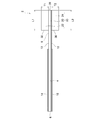
- FIG. 2 is a front view of the table tennis racket 2 according to the first embodiment of the present invention when viewed in the direction of arrow A1 in FIG. 1.
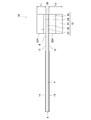
- 1 is a side view showing a table tennis racket 2 according to a first embodiment of the present invention. It is a side view for explaining adjustment of grip height T of a table tennis racket concerning a 1st embodiment of the present invention. It is a side view for explaining adjustment of the grip length of the table tennis racket concerning a 1st embodiment of the present invention.
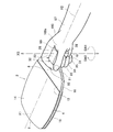
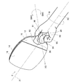
- FIG. 2 is a perspective view showing a state in which the user grips the table tennis racket 2 according to the first embodiment of the present invention so that the grip is rolled by a finger.
- FIG. 2 is a perspective view showing a state in which the table tennis racket 2 according to the first embodiment of the present invention is gripped shallowly by the user's thumb, index finger and middle finger at three points.
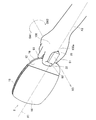
- FIG. 2 is a perspective view showing a state where the table tennis racket 2 according to the first embodiment of the present invention is gripped by the user, with the back of the hand facing upward.
- FIG. 2 is a perspective view showing a state in which the user grips the table tennis racket 2 according to the first embodiment of the present invention so that the grip is rolled by a finger.
- FIG. 2 is a perspective view showing a state in which the table tennis racket 2 according to the first embodiment of the present invention is gripped shallowly by the user's thumb, index finger and middle finger at three points.
- FIG. 2 is
- FIG. 2 is a perspective view showing a state where the table tennis racket 2 according to the first embodiment of the present invention is gripped by the user and the back of the hand is directed downward. It is a side view showing table tennis racket 2A concerning a 2nd embodiment of the present invention. It is an end elevation of a grip of 2 A of table tennis rackets concerning a 2nd embodiment of the present invention. It is the side view which showed the state which the user held table tennis racket 2A which concerns on 2nd Embodiment of this invention with the virtual line. It is a side view showing the modification of the grip part of table tennis racket 2B concerning a 2nd embodiment of the present invention.
- FIG. 13 It is a partial perspective view which shows the detail of the notch part 25b of the table tennis racket 2B which concerns on 2nd Embodiment of this invention. It is a side view showing a modification of a palm contact surface of a grip of table tennis racket 2C of a second embodiment of the present invention. It is a side view showing table tennis racket 2D concerning a 3rd embodiment of the present invention. It is a top view of the grip part of the table tennis racket 2D shown in FIG. 13, and shows an example of the shape of the support plate 64. FIG. It is a top view of the grip part of the table tennis racket 2D shown in FIG. 13, and shows another example of the shape of the support plate 64. FIG.
- FIG. 13 It is a top view of the grip part of the table tennis racket 2D shown in FIG. 13, and shows another example of the shape of the support plate 64.
- FIG. It is a side view showing modification 2E of a table tennis racket concerning a 3rd embodiment of the present invention. It is a side view showing table tennis racket F concerning a fourth embodiment of the present invention. It is a side view showing table tennis racket G concerning a 5th embodiment of the present invention. It is a perspective view of the grip part of the table tennis racket G which concerns on 5th Embodiment of this invention.
- the table tennis racket 2 according to the first embodiment of the present invention is provided on a flat blade 4 and a base end portion 8 opposite to a distal end portion 6 of the blade 4 as shown in FIGS. 1 to 3.
- the blade 4 is a hitting portion that hits a ball via rubber.
- the blade 4 employs a plywood type formed of a plywood obtained by stacking a plurality of wooden boards.
- a plywood type blade containing a special material in which a special material is sandwiched in an intermediate layer of the plate material constituting the plywood may be employed.
- the blade 4 is not limited to the plywood type, and may be a single veneer type including only one solid wooden board.
- the shape of the blade 4 in plan view is not particularly limited, and any shape can be adopted. In the present embodiment, as shown in FIG. 1, a so-called rounded shape is adopted.
- the first rubber 14 and the second rubber 18 are not particularly limited, and rubber of any kind and material can be adopted. In many cases, a rubber according to the player's preference is separately purchased and attached to the blade. . Since rubber increases the weight of the racket when pasted, in consideration of the increase in weight, the first side is heavy, but rubber suitable for aggressive batting is often applied to the ball on the second side. It is better to select a rubber which is lighter than the first surface and which is advantageous for the drive.
- the table tennis racket according to the present invention is characterized in that the racket is gripped by an "eagle grip" which is completely different from the conventional pen holder grip and shake hand grip, as will be described in detail later, forehand stroke and backhand stroke. In both cases, it is usually assumed that both the front and back surfaces of the blade are used. However, even when rubber is applied only to the first surface, the racket holding method using the “Eagle grip” can hit the fore and back more powerfully than the pen holder grip hitting method.
- the rubber to be attached to the racket is optional, and it is optional to attach rubber suitable for rotating the ball or a rubber suitable for the above-mentioned aggressive batting method with high speed on any of the front surface and the back surface, Further, as will be described later, it is possible to freely switch the front side to the back side and the back side to the front side by rotating the grip of the racket during the game. Therefore, it does not matter which of the surfaces is referred to as “front surface” and the other surface is referred to as “back surface”, particularly in the first embodiment.
- the grip 10 is a portion that the user grips with his / her hand, and is provided at the base end portion 8 of the blade 4 so as to protrude from the outer peripheral edge of the blade 4.
- the grip 10 is provided on the grip core 20 extending from the base end portion 8 of the blade 4 so as to protrude outward, and on the first surface 12 side of the blade 4 in the grip core 20.
- the grip core 20 is a portion extending from the outer peripheral edge of the base end 8 of the blade 4, and is usually integrally formed of the same material as the blade 4. For this reason, the thickness of the grip core 20 is usually the same as the thickness of the blade 4.
- the first protruding block 22 has a rectangular parallelepiped shape.
- the material used for the first protruding block 22 is not particularly limited, but preferably a cork material is used. That is, the first protruding block 22 is formed of a cork material processed into a rectangular parallelepiped shape. The formed first projecting block 22 is joined to the grip core body 20 on the side of the first surface 12 of the blade 4.
- the second protruding block 24 also has a rectangular parallelepiped shape.
- the material used for the second protruding block 24 is not particularly limited, a cork material is also preferably used for this member. That is, the second protruding block 24 is formed of a cork material processed into a rectangular parallelepiped, and is joined to the grip core 20 on the side of the second surface 16 of the blade 4.
- An end surface 25 of the protruding block 24 located on the side opposite to the end portion 6 of the blade 4 is flush with each other, and forms a terminal surface 26 of the grip 10 in cooperation with each other.
- the end surface 26 serves as a palm contact surface 28 for contacting the palm of the user when the grip 10 is gripped by the user.
- the end surface 21 of the grip core 20, the end surface 23 of the first protruding block 22, and the end surface 25 of the second protruding block 24 are integrally formed.
- the palm contact surface 28 is formed, but it is not always necessary for the three members to cooperate to form the palm contact surface 28, and at least one of these three members may be formed. .
- the end surface 30 of the first protruding block 22 on the tip end 6 side of the blade 4 indicates the user's index finger 92 (FIGS. 6, 7A, 7B). That is, the tip 6 side of the blade 4 in the first protruding block 22 serves as a pointing finger hanging portion on which the user's pointing finger 92 is hooked (see FIG. 8).
- the protruding height T1 of the blade 4 from the first surface 12 in the first protruding block 22 is determined. It is sufficient if it has a dimension (height) sufficient to catch the finger. Preferably, the dimension is set to be approximately the same as the width (thickness of the finger) of the index finger 92.
- the middle finger contact surface 36 that contacts at least the middle finger 93 of the user, as shown in FIG. It becomes.
- the tip 6 side of the blade 4 in the second protruding block 24 is a middle finger hook for the user to put the middle finger 93 on (see FIG. 9).
- the protruding height T2 of the blade 4 from the second surface 16 of the second protruding block 24 is equal to the middle finger 93. It is sufficient that the middle finger 93 has a size (height) sufficient to be caught, and is preferably set to be approximately the same as the thickness of the middle finger 93.
- the height T of the first protruding block 22 and the second protruding block 24 from the blade surface can be arbitrarily set by the height adjusting member according to the size and preference of the user's hand and fingers.
- the table tennis racket 52 shown in FIG. 4 includes a grip 10 having a first height adjustment member 54 disposed between the grip core 20 and the first protruding block 22, a grip core 20 and the second protruding block 24. And a second height adjusting member 56 disposed between the two.
- the first height adjusting member 54 is a member for adjusting the protruding height T1 of the first protruding block 22 located on the first surface 12 side from the first surface 12, and for increasing or decreasing the protruding height T1.
- the material used for the first height adjusting member 54 is not particularly limited, but preferably a cork material is used.
- the first height adjusting member 54 is joined to the first surface 12 of the blade 4 in the grip core 20. Then, the first protruding block 22 is joined to the upper side of the first height adjusting member 54 in FIG.
- the second height adjusting member 56 is a member for adjusting the projecting height T2 of the second projecting block 24 located on the second surface 16 side from the second surface 16. And has a desired height dimension to increase or decrease the protruding height T2, and is joined to the second surface 16 of the blade 4 of the gripping core 20, and the second height adjusting member 56 in FIG.
- the second protruding block 24 is joined to the lower side of.
- the projecting height T2 of the second projecting block 24 whose height has been adjusted by the second height adjusting member 56 is, for example, approximately the same as the thickness (width) of the middle finger 93 of the user and the thickness of the ring finger 94.
- the second protruding block 24 can put not only the middle finger 93 but also the ring finger 94 on the middle finger contact surface 36A.
- the protrusion height T2 of the second protrusion block 24 whose height has been adjusted by the second height adjustment member 56 is, for example, approximately the same length as the thickness of the middle finger 93 and the thickness of the ring finger 94 and the little finger 95.
- the second protruding block 24 can be gripped, and the stability when gripping the grip 10 is increased.
- the height (length) of the grip 10 in the direction orthogonal to the plate surface of the blade 4 is adjusted.
- a grip that fits the size of the user's hand can be formed.
- the ring finger and the little finger cooperate with each other to facilitate adjustment when grasping the grip.
- the length may be set as appropriate depending on the degree of force applied, the feeling, and the like. For example, when the user's palm 99 is brought into contact with the palm contact surface 28 (see FIGS. 6, 7A, and 7B), which joint of the index finger 92 of the user is bent on the index finger contact surface 32.
- the appropriate value of the length L1 of the first protruding block 22 is determined depending on whether or not the pointing finger 92 is put on the state, and the same applies to the length L2 of the second protruding block 22.
- FIG. 6 is a diagram showing the names of fingers and palms and the locations of the respective parts, and will be described using academic terms commonly used in the fields of medicine, technology, and the like, or terms equivalent thereto.
- the fingers shown in FIG. 6 are, in order from the right, the thumb 91, the index finger (index finger) 92, the middle finger 93, the ring finger 94, and the little finger 95, and the base of the thumb 91 of the palm 99.
- the bulging portion in the vicinity is called a ball of the thumb 96 and the bulging portion near the base of the other four fingers is called a ball of the fingertip 97.
- palm lines characteristic wrinkles appear for each person in accordance with the movement of the hand, and these are called palm lines.
- the palm line appears at an approximately constant position depending on how the skeleton, muscles, and hands are used.
- a palm line 99a runs horizontally from the little finger 95 toward the index finger 92 near the base of the fingertip ball 97, and the palm line 99a is called an emotion line in the field of palm surgery.
- the intelligence line 99b runs diagonally upward from the lower part of the figure toward the emotion line 99a so as to join the emotion line 99a, and furthermore, the life line diagonally upwards from below the intelligence line 99b along the foot of the thumb ball 96.
- 99c is running.
- the part of the palm 99 where the palm contact surface 28 of the table tennis racket according to the present invention abuts during use is formed between the above-mentioned thumb ball 96 and the fingertip ball 97, especially between the part near the base of the index finger 92. 6, a region 98 shown by hatching in FIG. 6 (this region is referred to as a “palm grip receiving portion”) 98, and the above-mentioned intelligence line 99b in FIG. Bounds the border.
- the index finger 92 includes a portion of the distal phalanx 92a (the bone of the portion of the fingertip with the nail), a portion of the middle phalanx portion 92b (the bone of the middle portion of the finger), and a base phalanx 92c (the finger) Of the distal phalanx 92a and the middle phalanx 92b in a state where the index finger 92 is bent at the joint thereof. And it is difficult to bring the proximal phalanx 92c into contact.
- the middle finger 93 includes a portion of the distal phalanx 93a from the tip, a portion of the middle phalanx portion 93b, and a portion of the base phalanx 93c.
- the joint of the middle finger 93 is bent,
- the site of the distal phalanx 93a, the site of the middle phalanx 93b, and the site of the base phalanx 93c can be brought into contact.
- the length L1 of the first protruding block 22 is selected based on the palm line (for example, the intelligence line 99b) shown in FIG. 6 and the side surface to which the index finger 92 of the first protruding block 22 is attached, the following method will be described.
- the palm contact surface 28 is pressed against the palm grip receiving portion 98 so that the side edge 28a (see FIG. 1) of the palm contact surface 28 is directed to the intelligence line 99b of the palm 99, and the index finger 92 is moved to the second position.
- the distance from the palm contact surface 28 to the distal end joint position 92d of the index finger 92 is determined so as to be closely attached to the side of the one protruding block 22, and this is calculated as the first protruding block. 22 may be set to the appropriate length L1.
- the distance between the emotion line 99a of the racket user's palm and the tip joint position 92d of the index finger 92 may be measured, and the appropriate length L1 of the first protruding block 22 may be set based on the measured value.
- the appropriate length L2 of the second protruding block 25 can be easily set by adding the difference between the tip joint positions of the index finger 92 and the middle finger 93 from the appropriate length L1 of the first protruding block 22 obtained as described above. it can.
- the table tennis racket 82 shown in FIG. 5 has a grip 110 including a first protruding block 122, a grip core body 120, and a second protruding block 124, and the length L1 of the first protruding block 122 and the second protruding block 124. , L2 are different from each other.
- the first protruding block 122 and the second protruding block 124 have the index finger contact surface 32 and the middle finger contact surface 36 with which the index finger 92 and the middle finger 93 of the user come into contact, respectively.
- the end surfaces 123 and 125 and the end surface 121 of the grip core body 120 are flush with each other, and when they cooperate with each other, the end surface of the grip 110, that is, when the grip is gripped by the user, the end surface of the grip 110 and the palm of the user.
- a palm contact surface 28 is formed to abut.
- the preferable length L1 of the first protruding block 122 is considered to be a length necessary for the user to grip the grip 110 most stably. Therefore, the length L1 of the first protruding block 122 is as described above.
- the joint 92d at the tip of the index finger 92 is bent so that the index finger 92 (part of the distal phalanx) is indicated. 32, and the tip joint position of the index finger 92 bent from the palm contact position of the palm contact surface 28 when the index finger 92 is disposed so as to closely adhere to the side of the first protruding block 122. It can be obtained as the distance to.
- the appropriate length L2 of the second protruding block 125 can be easily set from the appropriate length L1 of the first protruding block 122 obtained as described above by adding the difference between the tip joint positions of the index finger 92 and the middle finger 93. it can. Since the technical concept of the table tennis racket according to the present invention is to grasp the first and second blocks of the grip (Eagle grip), the table tennis racket may be used in accordance with the difference in the finger length of the index finger 92 and the middle finger 93, etc. By appropriately setting the length L1 of the one protruding block 122 and the length L2 of the second protruding block 125, the grip 110 can be more stably gripped.
- the height and length T1, T2, L1, and L2 of each part of the grip 10 depend on the size and preference of the user's hand if the above conditions are satisfied. It can be seen that selection of which part is to be brought into contact with the contact surface, setting of the length L and height T, and the like are arbitrarily possible.
- the projecting height T2 of the second projecting block 24 is set to the same height as the projecting height T1 of the first projecting block 22 in the first embodiment.
- T1 and T2 are set to the same height, the ratio of the weight of the grip to the entire racket is smaller than when either one is increased, the weight of the entire racket can be reduced, and the burden on the user during the game can be reduced.
- the first protruding block and the second protruding block have the same protruding height, they have a symmetrical shape on the front and back, so that they can be easily used by hands and operability is improved.
- switching faces changing the grip of the table tennis racket from holding the first surface to the palm side and holding the second surface to the back side of the hand, changing the grip so that the first surface becomes the back side of the hand and the second surface becomes the palm side ( (Hereinafter referred to as "switching faces") can be performed easily even during a game, and variations of attacks can be increased.
- the blade 4 is sandwiched between the index finger 92 and the middle finger 93 (see FIG. 8), and the palm contact surface 28 of the grip 10 is brought into contact with the palm grip receiving portion 98 (the hatched area in FIG. 6).
- the index finger 92 and the middle finger 93 are bent to bring the index finger 92 into contact with the index finger contact surface 32, and the middle finger 93 is brought into contact with the intermediate finger contact surface 36.
- the index finger 92 is arranged so as to closely contact the side of the first protruding block 22, and the thumb 91 is arranged so as to closely adhere to the opposite side of the first protruding block 22. Is preferred.
- the ring finger 94 is bent along the middle finger 93, and the little finger 95 is bent along the ring finger 94.
- FIG. 7A shows a state in which the middle phalanx part 92b of the index finger 92 is brought into contact with the index finger contact end face 32 and the index finger contact end face 32 of the grip 22 is gripped so as to be wound deeply.
- the stability of the grip is improved. Details on how to grip the grip wound deeply will be described later.
- the distal phalanx part 92a of the index finger 92 is brought into contact with the index finger contact end surface 32 of the grip 22, and the tip of the index finger is made to a shallow contact (see FIG. 7B), and the middle finger 93 also makes the middle finger contact surface 36 of the grip 22 a shallow contact.
- the grip 22 can be grasped.
- the thumb 91 faces the first surface 12 with the tip 6 of the blade down, the vicinity of the right side of the finger contact surface of the base end 8 of the blade (the hatched area 8a shown in FIG. 7B) forms the mother.
- the grip 22 When the grip is held by strongly pressing the finger 91, the grip 22 can be stably and securely gripped by the three-point support of the index finger 92, the middle finger 93, and the thumb 91. Then, the first protruding block 22 is sandwiched between the index finger 92 and the thumb 91 from both sides, and the palm abutting surface 28 of the grip 10 abuts on the grip receiving portion 98 of the palm 99 to support the first protruding block 22. As the support point of the index finger 92 and the thumb 91 attached to the first protruding block 22 moves away from the grip receiving portion 98, and thus the palm contact surface 28, that is, as the length L1 of the first protruding block 22 increases, the grip 10 Can be stably gripped.
- the user brings the index finger 92 into contact with the index finger contact end surface 32 of the eleventh exit block 22 while supporting the side portion of the first projection block 22 with the index finger 92 and the thumb 91, and pushes the middle finger 93 to the second projection.
- the entire grip 10 of the table tennis racket 2 can be held so as to be wrapped in the grip receiving portion 98 of the palm 99, which is a so-called grab state, that is, an eagle (Eagle).
- the grip 10 can be gripped in a manner similar to gripping a prey (Grip: grip). In the present invention, the manner in which the grip is held in this manner is referred to as an “Eagle grip” in comparison with a conventional pen holder grip and a shake hand grip.
- the center axis X1 connecting the racket head of the table tennis racket 2 and the grip end is aligned with the forearm 97 of the user, as shown in FIG. It extends along the direction in which the axis X2 extends.
- the direction in which the plate surface of the blade 4 extends coincides with the direction in which the axis X2 of the user's forearm 97 extends, so that the Eagle grip does not have a crossing angle unlike the pen holder racket. . Therefore, the table tennis racket 2 is held without the plate surface of the blade being inclined with respect to the axis of the forearm of the user. Therefore, since the table tennis racket 2 can perform the forehand stroke and the backhand stroke as follows, the following effects can be obtained.
- the table tennis racket 2 is attached to the second surface 16 by simply pulling the table tennis racket 2 to the left side of the body with the back of the hand 98 up and the palm 99 down.
- the second rubber 18 is directed toward the opponent, so that if the player swings in this state, the ball can be hit with the second rubber 18 on the second surface 16.
- the backhand side ball can be easily processed using the second rubber 18 on the second surface 16 without having to twist the arm during the backhand stroke to turn the first surface 12 toward the opponent. Therefore, the handling on the backhand side is easier, faster and more effective than the pen holder racket using only the first surface.
- the back hand stroke hit on the second side is common in the case of shake hand stroke, but this hitting method is also used in pen holder rackets, and a while ago a world champion using this hitting method appeared in Chinese players Like, already common.
- This hitting method can be applied to a ball that has come in a wide range on the left and right because there is no intersection angle. 2) Swing around the middle finger (the "rotational swing” described above) to create an intense drive on the ball.
- the latter advantage creates a very advantageous situation for the batting player with the advantage not found in a shake handler that produces a drive by turning the wrist.
- the table tennis racket 2 can overcome the weakness in the backhand which is a problem with the pen holder racket, and enhances the backhand swing of the first surface with the pen holder racket. Thus, a more advantageous situation can be created for the shake handler.
- the center axis X1 extends in the direction along the direction in which the axis X2 of the forearm 97 of the user extends, the center axis of the racket is moved to the arm like a shake handle bracket. It can be driven without bending from the axis.
- the racket can be operated with a fingertip like a pen holder racket, the table tennis racket 2 according to the present invention has better operability on a table tennis table than a shake handler racket, and can be rotated upward on a table tennis table. Because it is easy to spin, it has excellent aggression on the table tennis table.
- the second rubber 18 on the 16 side can be easily turned to the other party.
- the ball can be hit with the second rubber 18 on the side of the second surface 16 in the forehand stroke.
- the method of hitting this forehand swing on the second surface (back surface) is a hitting method that has not been known in the table tennis world, or at least has not been practically used, and is extremely different from a normal forehand swing at a very different timing. An effective drive ball can be sent out, and the opponent will not be able to respond easily.
- This hitting method is suitable for hitting on the table of a ping-pong table, as in the case of performing a backhand swing on the second surface.
- the game on the platform following the service often determines the game, and is considered to be the definitive weapon of a fast-paced haste game.
- both the forehand stroke and the backhand stroke can be hit only with the rubber on the first surface side.
- only the rubber on the first surface can hit the ball in the forehand stroke, and can hit only the rubber on the second surface in the backhand stroke.
- the table tennis racket 2 according to the present invention hits the first rubber 14 on the first surface 12 and hits the second rubber 18 on the second surface 16 in the forehand stroke. Can be easily selected, and the hitting ball with the first rubber 14 on the side of the first surface 12 and the hitting ball with the second rubber 18 on the side of the second surface 16 can be easily selected even in the backhand stroke.
- the table tennis racket 2 according to the present invention is an excellent table tennis racket that can easily hit a wide variety of balls, compared to the conventional table tennis racket. This is also brought about by the shape of the grip (Eagle grip) that can grip the grip 10 in the above-described manner.
- the table tennis racket according to the present invention rotates clockwise around the longitudinal axis (X1 axis shown in FIG. 7A) of the first protruding block 22 with the middle finger and thumb in contact with the middle finger contact surface in the Eagle grip. If the twist and thumb are positioned at right angles to the blade surface, the blade surface will be positioned at right angles to the platform, making it easier to defend or attack a "short" penholder.
- This switching of the grip can facilitate smooth movement to “short” by providing an angled tapered portion or notch on the grip end surface on the second surface side.
- the end surface shape of the grip palm contact surface of the first embodiment is not particularly limited, such as a circle, an ellipse, and a rectangle, but the peripheral edge of the palm contact surface of the grip is a smooth curved surface. Is preferably formed on a flat surface having a ridgeline having an edge effect, which prevents slippage and provides a good grip feeling. However, the palm contact surface may be formed by a curved surface having a gentle peripheral edge. In this case, the grip is stably received at a desired position of the palm grip receiving portion 98, which will be described later in a third embodiment. It is preferable that means for performing the operations are provided.
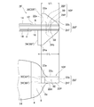
- FIGS. 10A and 10B show a table tennis racket 2A according to a second embodiment of the present invention.
- the racket 2A has a tapered portion (G) at the grip end face while maintaining the basic function of the eagle grip of the racket of the first embodiment. Or a notch) to add a grip function that makes it easier to defend or attack the “short” of a traditional pen holder racket. It has.
- G tapered portion
- a notch to add a grip function that makes it easier to defend or attack the “short” of a traditional pen holder racket. It has.
- the grip shape of the second embodiment those having substantially the same configuration and function as the table tennis racket 2 according to the first embodiment already described, or analogous to the table tennis racket 2 according to the first embodiment will be described.
- the same reference numerals as in the table tennis racket 2 according to the embodiment denote the same, and a detailed description thereof will be omitted (the same applies to other embodiment
- FIG. 10A shows only the grip 10A of the table tennis racket 2A of the second embodiment, and only the portion corresponding to the grip 10 of the first embodiment, which is surrounded by a circle C shown by a dashed line in FIG. Is shown.
- the grip 10A of the table tennis racket 2A shown in FIG. 10A includes a first protruding block 22 as a first protruding member and a second protruding block 24A as a second protruding member with the grip core body 20 interposed therebetween.
- a tapered surface 29A is formed by cutting out the terminal surface of 24A.
- the tapered surface 29A is formed with the blade second surface 16 at an inclination angle ⁇ of 30 to 60 degrees, and about 45 degrees in the example shown in FIG. 10A.
- the tapered surface 29A is not particularly limited. As shown in FIGS. 10A to 10C, the tapered surface may be a flat surface viewed from a direction orthogonal to the tapered surface, or will be described later with reference to FIG. 11A. As described above, it may be a curved surface.
- the first protruding block 22 is in contact with the grip core body end face 21 on the first surface 12 side of the blade, and is disposed at right angles to the grip core 20.
- the end surface 23 of the first protruding block 22 and the end surface 21 of the gripping core body 20 are flush with each other to form the palm contact surface 28A.
- the grip 10A of the table tennis racket 2A shown in FIG. 10A has a length L1, L2 of the first protruding block 22 and the second protruding block 24A of 35 mm and 40 mm, respectively, and the terminal surface 23 of the first protruding block 22A, that is, the palm. If the distance between each of the index finger contact surface 32A and the middle finger contact surface 36A from the contact surface 28A is set to the difference between the finger lengths of the index finger 92 and the middle finger 93, a good grip feeling can be obtained, and the grip 10A can be secured. You can grab it.
- the second protruding block 24A has an end surface 29A formed by an inclined surface to form a tapered portion, and this tapered portion is used when the eagle grip shifts to defense or attack of "short" of the pen holder.
- the movement of the palm grip receiving portion 98, which has been in contact with the palm contact surface 28A, is easily and smoothly performed.
- the palm grip receiving portion 98 see FIG. 6
- the end surface 29A that forms the tapered portion of the second protruding block 24A can be referred to as a “second palm contact surface”.
- the table tennis racket 2A is changed from the eagle grip to the “short” grip by pressing the second protruding block 24A with the middle finger 93 while supporting the first protruding block 22 with the index finger 92, and using the thumb 91.
- the blade base end 8 is pushed up, and the thumb 91 is pressed so as to stand upright with respect to the blade surface, and a racket around the axis X1 shown in FIG.
- a swing that twists an arm so that a ball can be captured on a first surface of a racket, which is a feature of a pen holder, is realized using a table tennis racket 2A.
- the ball hit by the opponent toward the front can be hit with a backhand in a racket, and can be hit back in a desired direction with a skillful fingering in a “short” hitting method.
- Excellent operability on a table can be realized.
- the grip 10B of the table tennis racket 2B shown in FIG. 11A includes a first protruding block 22B as a first protruding member and a second protruding block 24B as a second protruding member with the grip core body 20 interposed therebetween.
- the first protruding block 22B disposed on the first surface 12 side is mounted so as to protrude outward in the longitudinal direction from the terminal end surface 21 of the grip core body 20, and a palm contact surface 28B is formed at the protruding end 23B.
- the second protruding block 24B is arranged on the distal end side of the blade in contact with the terminal end surface 21 of the grip core.
- the end surface 23B of the first protruding block 22B constitutes the palm contact surface 28B.
- the end surface 30 of the first protruding block 22B is the index finger contact surface 32B, and the second protruding block.
- the end surface 34 of 24B is a middle finger contact surface 36B.
- the difference between the distance between each of the palm contact surfaces 28B of the index finger contact surface 32B of the first projecting block 22B and the middle finger contact surface 36B of the second projecting block 24B is set to the difference between the finger lengths of the index finger 92 and the middle finger 93. By doing so, a good grip feeling can be obtained, and the grip 10B can be grasped firmly.
- the grip 10B shown in FIG. 11A has a terminal surface formed by cutting out a portion 25b (see FIG. 11B) indicated by oblique lines in the drawing, which forms a columnar body having a four-part elliptical cross section from the second projecting block 24B.
- the terminal surface 29B is a second palm contact surface
- the palm grip is attached to the second palm contact surface 29B, as can be easily inferred from the description made with reference to FIGS. 10A to 10C.
- a pen holder type grip can be realized without discomfort, and also in this case, a "short" hitting method on a table, which is a feature of the pen holder racket, is possible.
- FIG. 12 shows a table tennis racket 2C according to another preferred modification of the second embodiment.
- the grip 10C of the table tennis racket 2C includes a first protruding block 22C as a first protruding member and a second protruding block 24C as a second protruding member with the grip core 20 interposed therebetween.
- the second protruding block 24C has a shape similar to that of the second protruding block 24A of the second embodiment shown in FIG. 10A, and is formed by cutting off a part of the end surface thereof. The difference is that the surface 29C forms a larger angle (about 60 °) than the tapered surface 25A formed in the second embodiment of FIG. 10A.
- the end surface 21C of the grip core 20 is formed so as to form a substantially cylindrical surface and protrude outward.
- the terminal surface 23C of the first protruding block 22C also forms a tapered surface that is inclined so as to be parallel to the terminal surface 29C of the second protruding block 24C, and the blade first surface 12 to which the first protruding block 22C is adhered. Above, it is smoothly connected to the end surface 21C of the grip core body 20 in a curved surface. Therefore, in the case of the table tennis racket 2C shown in FIG.
- one of the table tennis rackets 2C formed by the end surface 21C of the cylindrical grip core body and the end surface 23C of the first protruding block 22C that are smoothly connected by a curved surface is formed.
- a gentle valley-shaped depression having a longer inclination than the other becomes the palm contact surface 28C.
- both the palm contact surface 28C and the palm grip receiving portion 98 are fitted and fitted to each other, and the palm contact surface 28C is stably received and held in the palm grip receiving portion 98. Prevents slippage and gives the racket user (player) a stable grip without slippage.
- the inclined end surface 23C of the first protruding block 22C and the end surface 21C that forms the cylindrical surface of the grip core body 20 and protrudes outward form a palm contact surface 28C.
- the end surface 30 of the first protruding block 22C is the index finger contact surface 32C
- the end surface 34 of the second protruding block 24C is the middle finger contact surface 36C.
- the tapered surface 29C (second palm contact surface) of the second protruding block 24C is a palm grip that has been in contact with the palm contact surface 28C when shifting from the eagle grip to the defense or attack of the "short" of the pen holder.
- the receiving portion 98 can be easily and smoothly moved. Then, when the palm grip receiving portion 98 (see FIG. 6) is applied to the terminal surface 29C of the tapered portion, the tapered portion becomes the second palm contact surface, and a pen holder type grip can be realized without discomfort.
- the "short" hitting method can also be performed with the table tennis racket of the present invention.
- FIG. 10C A third embodiment of a table tennis racket according to the present invention will be described with reference to FIG.
- the table tennis racket 2D according to the third embodiment is different from the table tennis racket 2 according to the first embodiment shown in FIGS. 1 to 3 and the table tennis racket according to the modification illustrated in relation to the first embodiment in FIGS.
- the table tennis racket 2A according to the second embodiment shown in FIG. 10C or the table tennis racket according to the modified example illustrated in relation to the second embodiment is grip-slip-prevented or grips the grip, the end surface of the grip. Is further added to a means for positioning the user at a desired position on the palm.
- the slip prevention function of the grip provided by the end face shape of the palm contact surface has already been partially illustrated in the description of the first embodiment and the second embodiment.
- the grip 10D of the table tennis racket 2D of the third embodiment shown in FIG. 13 includes a first protruding block 22D as a first protruding member and a second protruding block 24D as a second protruding member with the grip core body 20 interposed therebetween.
- the terminal surface 23D of the first protruding block 22D, the terminal surface 21 of the gripping core body 20, and the terminal surface 25 of the second protruding block 24 are surfaces. They cooperate to form the end surface 26 of the grip 10D.
- the terminal surface 26 constitutes a palm contact surface 28D for contacting the palm of the user when the grip 10D is gripped by the user.
- the end surface 30 of the first protruding block 22D is shown. Is the index finger contact surface 32D, and the end surface 34 of the second protruding block 24D is the middle finger contact surface 36D.
- the palm contact surface 28D is received by the grip receiving portion 98 (see FIG. 6) of the palm 99 when the user grips the grip 10D.
- a portion 100a (see FIG. 7A) near the palm back 100 near the palm grip receiving portion 98 located on the palm 99 side is referred to as a Koya.
- the first protruding block 22D further includes a support plate 64 disposed on the upper surface thereof.
- the support plate 64 includes the index finger 92 and the thumb 91 that grip the first protruding block 22D, and the support surface 66c that contacts at least one of the above-mentioned indentation portions 100a (see FIG. 7A).
- the support plate 64 has a tail portion 66 protruding from the palm contact surface 28D in a direction opposite to the tip portion 6 of the blade 4.
- the lower surface 66c of the tail portion 66 is brought into close contact with or in contact with the lower surface 66c of the support plate by the user's instep portion 100a, so that the palm grip receiving portion 98 (
- the palm abutment surface 28 can be guided to the desired position (see FIG. 6) and can be addressed to that position, and the table tennis racket 62 is prevented from moving (sliding).
- grip stability when the table tennis racket 62 is gripped and when swinging is increased.
- the support plate 64 has a rectangular plate shape longer and thinner than the first protruding block 22D (see FIG. 14A).
- the material used for the support plate 64 is not particularly limited, but it is preferable to use lightweight wood having relatively high bending strength.
- the height adjusting members 54 and 56 used in the second embodiment may be added, and the height and length of the first protruding block 22D and the second protruding block 24 may be changed. What is necessary is just to set suitably according to the length of a user's finger, the size of a palm, etc.
- the shape of the support plate is such that the plate side edge 66a extends from the index finger contact surface 32D of the first protruding block 22D to the palm contact surface 28D so that the side edge of the side wall on both sides of the first protruding block 22D. May be gradually bulged outward so as to surround the lower surface 66c of the tail portion 66 so as to form a flange.
- the thumb 91, the index finger 92, and the indentation portion 100a (see FIG. 7A) of the user holding the grip 10D are in close contact with or contact with the lower surface 66c of the support plate, so that the movement of the grip position is limited. , Can increase grip stability.
- a portion corresponding to the support plate 64 may be integrally formed by one member. That is, in the first protruding block 22D, the tail portion 66 may be provided integrally so that the upper portion of the end surface 23 extends rearward. Further, a portion 25b indicated by oblique lines in FIG. 13 is cut off in the same manner as described with reference to FIG. 11A, and a notch portion 25b is provided to form a second palm contact surface 29D, thereby reducing the "short" of the pen holder. Can be made smooth and easy. In order to make the transition to “short” smooth and easy, the tail portion 66 of the support plate should have the shape shown in FIGS. 14A and 14C so as not to hinder the use of the index finger 92 and the thumb 91. Are preferred.
- the table tennis racket 2E shown in FIG. 15 includes a palm contact surface 28E that is inclined such that the angle ⁇ of the blade 4 with respect to the first surface (surface) 12 is an acute angle.
- the palm contact surface 28E is inclined in this manner, the support plate 64 and the inclined palm contact surface 28E cooperate, and when the user grips the grip 10E, the palm contact surface 28E is moved. It fits into the optimal receiving position of the palm 99, that is, the palm grip receiving portion 98 without displacement, and prevents the racket from slipping, and has an effect of increasing grip stability and user's sense of stability.
- the angle ⁇ is not particularly limited, and is preferably set to, for example, about 70 degrees to 85 degrees because it matches the palm grip receiving portion 98 when the palm 99 is grasped.
- the shape of the lower surface 66c of the tail portion 66 can be formed into various shapes illustrated in FIGS. 14A to 14C. In this case, the indentation 100a and the finger of the user holding the grip 10E can be securely held by the lower surface 66c of the support plate, and the stability of the grip can be increased.
- a portion 25b indicated by oblique lines of the palm contact surface 28E of the second projecting block 24E is notched.
- the second palm contact surface 29E can be formed, and the transition to the “short” hitting method, which is a feature of the pen holder racket, can be performed quickly and easily.
- FIG. 16 shows a table tennis racket 2F according to a fourth embodiment of the present invention.
- the grip 10F of the racket 2F includes a grip core 20 that forms a part of the blade 4, a first protruding block 22F as a first protruding member with the core 20 interposed therebetween, and a second protruding member 22 as a second protruding member.
- the grip width and the length are set to appropriate lengths that provide a feeling of fitting to the palm and fingers when the grip 10F is gripped, similarly to the grip 10 of the first embodiment.
- the grip core body 20 includes a terminal surface 21F located on the side opposite to the distal end portion 6 of the blade 4, and the terminal surface 21F has a cylindrical shape.
- the first protruding block 22F is disposed on the first surface (front surface) 12 side of the blade 4, and has a substantially trapezoidal shape as a whole.
- the end face 30 of the block 22F on the blade tip end 6 side is formed perpendicular to the gripping core 20, and when the grip 10F is gripped by the user, the finger 22 and the index finger 92 (see FIG. 6) of the user. It becomes the index finger contact surface 32F that comes into contact.
- the height of the end face 30 depends on the thickness of the index finger 92 of the user, but is set to an appropriate height according to the thickness of the index finger.
- a rectangular horizontal surface 22a which is perpendicular to the end surface 30 and is parallel to the gripping core 20, and an inclined surface 22b smoothly connected to the horizontal surface 22a and the curved surface of the terminal surface 21F are provided.
- the second protruding block 24F also has a substantially trapezoidal shape as a whole, and is disposed on the second surface (back surface) 16 side of the blade 4.
- the end surface 34 of the block 24F on the blade tip 6 side is formed perpendicular to the grip core 20, and when the grip 10F is gripped by the user, at least the middle finger 93 and the ring finger 94 of the user (FIG. 6) and the middle finger contact surface 36F. Therefore, the height of the end face 34 is appropriately set according to at least the thickness of the finger including the middle finger 93 and the ring finger 94, although it depends on the thickness of the user's finger.
- the middle finger 93 and the ring finger 94 as well as the little finger 95 can be put on the middle finger contact surface 36F of the second projecting block 24F.
- the height of the end face 34 is equal to the thickness of the little finger 95. It is set to the height.
- the second protruding block 24F is taller than the first protruding block 22F, and the end face 34 of the block 24F is more bladed than the end face 30 of the first protruding block 22F due to the difference in the length of the index finger and the middle finger. It will be located at a position close to the tip 6.
- the block 24F also includes a rectangular horizontal surface 24a that is perpendicular to the end surface 34 and is parallel to the gripping core 20, and an inclined surface 24b that smoothly connects the horizontal surface 24a to the curved surface of the terminal surface 21F.
- a curved end surface 21F and a part of the inclined surface 22b near the end surface 21F become a palm contact surface 28F.
- the index finger 92 contacting the index finger contact surface
- the middle finger 93 contacting the middle finger contact surface
- the blade 4 It is extremely important to use three fingers of the thumb 91 that presses the base end region 8a (see FIG. 7B) near the index finger contact surface on the one surface (front surface) 12 side. The direction of the hitting of the blade 4 is freely controlled.
- the grip indicating finger contact surface 32F of the table tennis racket of the present invention is separated from the grip core 20 and located at the blade base end 8 on the blade tip 6 side. Even if the index finger 92 is brought into deep contact with the index finger contact surface 32F (see FIGS. 7A and 7B), the proximal end portion is sufficient for the thumb 91 to press the vicinity of the index finger contact surface. The area 8a must be reserved. Also, in the second protruding block 24F, the middle finger contact surface 36F is positioned at the blade base end portion 8 on the blade second surface (back surface) 16 side due to the difference in finger length between the index finger 92 and the middle finger 93 (see FIG. 16). ).
- the block lengths of the first protruding block 22F and the second protruding block 24F are set to be appropriately set in accordance with the length of the user's finger.
- the first protruding block 22F is configured such that the index finger contact surface 32F is separated from the terminal surface 21F of the grip core 20 by a distance Lf1. It is attached so that it becomes.
- the second protruding block 24F is attached such that the middle finger contact surface 36F is at a distance Lf2 from the end surface 21F of the grip core 20.
- a positioning pin 50 is inserted into a predetermined position of the grip core 20 so as to penetrate the grip core 20.
- the pin 50 is driven into the core body 20, and the pin 50 is fitted into a pin hole correspondingly drilled in the first protruding block 22 ⁇ / b> F and the second protruding block 24, and the first protruding block 22 ⁇ / b> F and the second protruding block 24 are attached to the grip core body 20. You can also paste it.
- the positioning pins 50 the index finger contact surface 32F and the middle finger contact surface 36F can be accurately positioned, and can withstand an excessive gripping force on the grip 10F and increase the bonding strength.
- first protruding block 22F and the second protruding block 24F each having a length suitable for the user are attached to the longer gripping core 20 with reference to the positioning pin 50, and the extra protruding gripping core 20 is attached.
- the end surface 21F may be scraped off, and the manufacture of table tennis rackets is facilitated corresponding to the grips 10F of various lengths.
- the blade 4 is sandwiched between the index finger 92 and the middle finger 93, the index finger 92 is brought into contact with the index finger contact surface 32F, and the middle finger 93 is set in the middle finger. Contact the contact surface 36F. At this time, the palm contact surface 28F of the grip 10F is brought into contact with the palm grip receiving portion 98 so as to cover the palm 99.
- the index finger 92 is arranged so as to closely contact the side 22c of the first protruding block 22F, and the thumb 91 is arranged so as to closely contact the side 22d on the opposite side of the first protruding block 22F.
- the grip 10F can be gripped in the already described gripping state (“Eagle grip”).
- a driving method in which a stronger spin is applied by the above-described “rotational swing” is realized.
- the grip 10F of the fourth embodiment has an advantage that the palm is easily fitted and fitted to the inclined surface 22b by providing the first protruding member 22F having a triangular shape in a side view and including the inclined surface 22b. Further, for example, a depression 22e may be formed in the end surface 30 so that the index finger 92 that contacts the index finger contact surface 32F fits.
- the end surfaces 30, 34 are cut in accordance with the finger length of the user, and the grip lengths Lf1, Lf2 are adjusted to form the index finger contact surface 32F and the middle finger contact surface 36F.
- the horizontal surfaces 22a, 24a of the first protruding block 22F and the second protruding block 24F are set to have appropriate lengths as a cutting allowance.
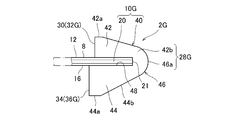
- the grip 10G of the racket 2G includes a grip core body 20 that forms a part of a blade, and a protruding block body 40 that is attached and fixed to both surfaces of the core body 20.
- the first protruding block portion 42 adhered to the first surface (front surface) 12 side and the second protruding block portion 44 adhered to the second surface (rear surface) 16 side are integrally formed. In that it differs from the grip shape of the other embodiments.
- the protruding block body 40 includes a first protruding block portion 42, a second protruding block portion 44, and a grip end portion that integrally connects these block portions 42, 44. 46, a fitting groove 48 is formed between the opposing surfaces of the first projecting block 42 and the second projecting block 44.
- the grip core 20 is fitted into the fitting groove 48, and the protruding block body 40 is joined to the grip core body 20 with an adhesive to assemble the grip 10G.
- the first protruding block portion 42 has a substantially right-angled triangular side surface, is continuous with the index finger contact surface 32G orthogonal to the grip core 20, a horizontal surface 42a parallel to the grip core 20, and a grip end.
- the end surface 46a has a rectangular inclined surface 42b which is continuous with the terminal surface 46a, and has a shape similar to that of the first projecting block 22F of the fourth embodiment.
- the second protruding block portion 44 also has a substantially right-angled triangular side surface, and is connected to the middle finger contact surface 36G orthogonal to the grip core body 20, the middle finger contact surface 36G, and a horizontal plane 44a parallel to the grip core body 20, Further, a rectangular inclined surface 44b which is continuous with the terminal end surface 46a of the grip end 46 is provided, and has a shape similar to that of the second projecting block 24F of the fourth embodiment.
- the blade attachment positions of the index finger contact surface 32G and the middle finger contact surface 36G are adjusted with reference to the end surface 21 of the grip core 20.
- the grip 10G of various sizes according to the length of the palm or the finger can be attached to the blade 4.
- the palm contact surface 28G of the grip 10G is directed to and received by the palm grip receiving portion 98, as easily understood from the description of the other embodiments, and the index finger 92 is moved to the index finger contact surface 32G.
- the grip 10G can be gripped stably and securely by gripping the grip 10G.
- the second protruding block portion 44 of the grip 10G also has a triangular shape in a side view and includes an inclined surface 44b.
- the inclined surface 44b is the end surface 29A of the second protruding block 24A described in the second embodiment. It has the same function and effect as the inclined surface (tapered portion) formed in the above, and when the palm grip receiving portion 98 (see FIG. 6) is applied to the inclined surface 44b, it is possible to make a transition to a pen holder type grip without discomfort. Therefore, the "inclined surface 44b" adds a grip function to facilitate the defense or attack of the "short" of the traditional pen holder racket.
- a block body in which the first and second protruding block portions are integrally formed is used for a grip of a table tennis racket.
- the fifth embodiment is similarly applied to the first to third embodiments. be able to.
- the block body can be easily formed by injection molding of a resin or the like. Can be used to reduce the processing cost.
- Second rubber 20 Grip core 22, 22A-22F First protruding block (first protruding member) 24, 24B to 24F Second projecting block (second projecting member) 28, 28B to 28F palm contact surfaces 29A to 29F second palm contact surfaces 32, 32B to 32F index finger contact surfaces 36, 36B to 36F middle finger contact surface 40 projecting block body 40 42 First projecting member 44 Second projecting member 98 Palm grip receiving site 100 Back of hand 100a Koaiya
Landscapes
- Health & Medical Sciences (AREA)
- General Health & Medical Sciences (AREA)
- Physical Education & Sports Medicine (AREA)
- Position Input By Displaying (AREA)
- Golf Clubs (AREA)
- Prostheses (AREA)
- Addition Polymer Or Copolymer, Post-Treatments, Or Chemical Modifications (AREA)
Priority Applications (2)
| Application Number | Priority Date | Filing Date | Title |
|---|---|---|---|
| CN201980003417.4A CN111163846B (zh) | 2018-06-19 | 2019-06-17 | 乒乓球拍 |
| JP2020525723A JP7308825B2 (ja) | 2018-06-19 | 2019-06-17 | 卓球ラケット |
Applications Claiming Priority (4)
| Application Number | Priority Date | Filing Date | Title |
|---|---|---|---|
| JP2018-116120 | 2018-06-19 | ||
| JP2018116120 | 2018-06-19 | ||
| JP2018-196406 | 2018-10-18 | ||
| JP2018196406A JP6500156B1 (ja) | 2018-06-19 | 2018-10-18 | 卓球ラケット |
Publications (1)
| Publication Number | Publication Date |
|---|---|
| WO2019244837A1 true WO2019244837A1 (ja) | 2019-12-26 |
Family
ID=66092566
Family Applications (1)
| Application Number | Title | Priority Date | Filing Date |
|---|---|---|---|
| PCT/JP2019/023899 Ceased WO2019244837A1 (ja) | 2018-06-19 | 2019-06-17 | 卓球ラケット |
Country Status (4)
| Country | Link |
|---|---|
| JP (2) | JP6500156B1 (https=) |
| CN (1) | CN111163846B (https=) |
| TW (1) | TWI781324B (https=) |
| WO (1) | WO2019244837A1 (https=) |
Cited By (1)
| Publication number | Priority date | Publication date | Assignee | Title |
|---|---|---|---|---|
| US20240181312A1 (en) * | 2022-12-06 | 2024-06-06 | Nigel John Jones | Pincer Paddle |
Families Citing this family (3)
| Publication number | Priority date | Publication date | Assignee | Title |
|---|---|---|---|---|
| JP7469149B2 (ja) * | 2020-06-17 | 2024-04-16 | 明 安井 | 卓球ラケット |
| JP7360367B2 (ja) * | 2020-08-17 | 2023-10-12 | 義勝 熊谷 | 卓球用ラケット |
| JP2021086632A (ja) * | 2020-11-26 | 2021-06-03 | ユニファ株式会社 | シフト作成システム、及びプログラム |
Citations (2)
| Publication number | Priority date | Publication date | Assignee | Title |
|---|---|---|---|---|
| JPS63111168U (https=) * | 1987-01-13 | 1988-07-16 | ||
| KR100817249B1 (ko) * | 2007-03-02 | 2008-03-27 | 류종렬 | 이면 타법이 가능한 펜 홀더형 탁구 라켓 |
Family Cites Families (9)
| Publication number | Priority date | Publication date | Assignee | Title |
|---|---|---|---|---|
| CN2333421Y (zh) * | 1998-08-06 | 1999-08-18 | 张德祥 | 乒乓球拍 |
| JP2000354647A (ja) * | 1999-06-14 | 2000-12-26 | Takeshi Aoki | 卓球のラケット |
| CN2468529Y (zh) * | 2001-02-07 | 2002-01-02 | 刘笑觉 | 垂直拍柄乒乓球拍 |
| JP2003325715A (ja) * | 2002-05-09 | 2003-11-18 | Kazuo Yamazawa | 卓球用ラケット |
| TWM345622U (en) * | 2008-01-10 | 2008-12-01 | Ching-Fong Chen | Table tennis racket |
| CN102451549A (zh) * | 2010-10-28 | 2012-05-16 | 柳云波 | 佛耳式乒乓球拍底板 |
| CN205019672U (zh) * | 2015-09-16 | 2016-02-10 | 吕生龙 | 一种乒乓球横握拍 |
| KR200483855Y1 (ko) * | 2015-10-14 | 2017-07-03 | 유은호 | 탁구 라켓 |
| CN205598563U (zh) * | 2016-05-06 | 2016-09-28 | 赵兴昌 | 一种斜向横块宽颈侧握乒乓球拍 |
-
2018
- 2018-10-18 JP JP2018196406A patent/JP6500156B1/ja active Active
-
2019
- 2019-06-17 JP JP2020525723A patent/JP7308825B2/ja active Active
- 2019-06-17 CN CN201980003417.4A patent/CN111163846B/zh active Active
- 2019-06-17 WO PCT/JP2019/023899 patent/WO2019244837A1/ja not_active Ceased
- 2019-06-19 TW TW108121233A patent/TWI781324B/zh active
Patent Citations (2)
| Publication number | Priority date | Publication date | Assignee | Title |
|---|---|---|---|---|
| JPS63111168U (https=) * | 1987-01-13 | 1988-07-16 | ||
| KR100817249B1 (ko) * | 2007-03-02 | 2008-03-27 | 류종렬 | 이면 타법이 가능한 펜 홀더형 탁구 라켓 |
Cited By (1)
| Publication number | Priority date | Publication date | Assignee | Title |
|---|---|---|---|---|
| US20240181312A1 (en) * | 2022-12-06 | 2024-06-06 | Nigel John Jones | Pincer Paddle |
Also Published As
| Publication number | Publication date |
|---|---|
| JP6500156B1 (ja) | 2019-04-10 |
| TW202000276A (zh) | 2020-01-01 |
| JP7308825B2 (ja) | 2023-07-14 |
| JP2019217242A (ja) | 2019-12-26 |
| TWI781324B (zh) | 2022-10-21 |
| CN111163846B (zh) | 2021-10-29 |
| CN111163846A (zh) | 2020-05-15 |
| JPWO2019244837A1 (ja) | 2021-09-16 |
Similar Documents
| Publication | Publication Date | Title |
|---|---|---|
| JP7469149B2 (ja) | 卓球ラケット | |
| WO2019244837A1 (ja) | 卓球ラケット | |
| US20110098143A1 (en) | Shakehand type pingpong racket with supporting projection part | |
| US7993222B2 (en) | Table-tennis bat(pen-holding type) | |
| CN115970241A (zh) | 新式乒乓球拍 | |
| JP7100870B1 (ja) | 卓球ラケット | |
| JP2001112900A (ja) | 卓球用ラケット | |
| CN208651828U (zh) | 乒乓球拍 | |
| US20240181312A1 (en) | Pincer Paddle | |
| CN223416689U (zh) | 一种适于勾握式直板乒乓球拍 | |
| WO1993000969A1 (en) | A frame for table-tennis bats | |
| KR20170112301A (ko) | 수도지지부가 구비된 쉐이크 핸드형 탁구 라켓 | |
| CN205216116U (zh) | 一种改进型悬空斜向横块宽颈侧握乒乓球拍 | |
| CN211836199U (zh) | 一种直握乒乓球拍 | |
| CN218280472U (zh) | 一种直握乒乓球拍 | |
| CN104307150A (zh) | 一种乒乓球直拍横打新型球拍 | |
| CN204709735U (zh) | 一种宽颈横杠侧握乒乓球拍 | |
| CN209714204U (zh) | 一种乒乓球拍 | |
| CN103977545A (zh) | 一种鹰爪式乒乓球拍底板 | |
| KR20080111867A (ko) | 양면타법이 가능한 펜 홀더형 탁구라켓 | |
| JPH0630212Y2 (ja) | 卓球ラケット | |
| JP2025063968A (ja) | テニスラケット用のハンドル及びそれを備えたテニスラケット | |
| JP2005312579A (ja) | 卓球用ラケット | |
| JPH0538766Y2 (https=) | ||
| CN103143151B (zh) | 复握式乒乓球拍 |
Legal Events
| Date | Code | Title | Description |
|---|---|---|---|
| 121 | Ep: the epo has been informed by wipo that ep was designated in this application |
Ref document number: 19821670 Country of ref document: EP Kind code of ref document: A1 |
|
| ENP | Entry into the national phase |
Ref document number: 2020525723 Country of ref document: JP Kind code of ref document: A |
|
| NENP | Non-entry into the national phase |
Ref country code: DE |
|
| 122 | Ep: pct application non-entry in european phase |
Ref document number: 19821670 Country of ref document: EP Kind code of ref document: A1 |