WO2019239744A1 - 撮像制御装置、撮像制御方法、及びプログラム - Google Patents
撮像制御装置、撮像制御方法、及びプログラム Download PDFInfo
- Publication number
- WO2019239744A1 WO2019239744A1 PCT/JP2019/018270 JP2019018270W WO2019239744A1 WO 2019239744 A1 WO2019239744 A1 WO 2019239744A1 JP 2019018270 W JP2019018270 W JP 2019018270W WO 2019239744 A1 WO2019239744 A1 WO 2019239744A1
- Authority
- WO
- WIPO (PCT)
- Prior art keywords
- camera
- parameter group
- image quality
- quality evaluation
- imaging
- Prior art date
- Legal status (The legal status is an assumption and is not a legal conclusion. Google has not performed a legal analysis and makes no representation as to the accuracy of the status listed.)
- Ceased
Links
Images


Classifications
-
- G—PHYSICS
- G03—PHOTOGRAPHY; CINEMATOGRAPHY; ANALOGOUS TECHNIQUES USING WAVES OTHER THAN OPTICAL WAVES; ELECTROGRAPHY; HOLOGRAPHY
- G03B—APPARATUS OR ARRANGEMENTS FOR TAKING PHOTOGRAPHS OR FOR PROJECTING OR VIEWING THEM; APPARATUS OR ARRANGEMENTS EMPLOYING ANALOGOUS TECHNIQUES USING WAVES OTHER THAN OPTICAL WAVES; ACCESSORIES THEREFOR
- G03B7/00—Control of exposure by setting shutters, diaphragms or filters, separately or conjointly
- G03B7/08—Control effected solely on the basis of the response, to the intensity of the light received by the camera, of a built-in light-sensitive device
- G03B7/091—Digital circuits
-
- G—PHYSICS
- G06—COMPUTING OR CALCULATING; COUNTING
- G06T—IMAGE DATA PROCESSING OR GENERATION, IN GENERAL
- G06T7/00—Image analysis
- G06T7/0002—Inspection of images, e.g. flaw detection
-
- G—PHYSICS
- G06—COMPUTING OR CALCULATING; COUNTING
- G06V—IMAGE OR VIDEO RECOGNITION OR UNDERSTANDING
- G06V10/00—Arrangements for image or video recognition or understanding
- G06V10/10—Image acquisition
- G06V10/12—Details of acquisition arrangements; Constructional details thereof
- G06V10/14—Optical characteristics of the device performing the acquisition or on the illumination arrangements
- G06V10/147—Details of sensors, e.g. sensor lenses
-
- G—PHYSICS
- G06—COMPUTING OR CALCULATING; COUNTING
- G06V—IMAGE OR VIDEO RECOGNITION OR UNDERSTANDING
- G06V10/00—Arrangements for image or video recognition or understanding
- G06V10/70—Arrangements for image or video recognition or understanding using pattern recognition or machine learning
- G06V10/82—Arrangements for image or video recognition or understanding using pattern recognition or machine learning using neural networks
-
- G—PHYSICS
- G06—COMPUTING OR CALCULATING; COUNTING
- G06V—IMAGE OR VIDEO RECOGNITION OR UNDERSTANDING
- G06V10/00—Arrangements for image or video recognition or understanding
- G06V10/98—Detection or correction of errors, e.g. by rescanning the pattern or by human intervention; Evaluation of the quality of the acquired patterns
- G06V10/993—Evaluation of the quality of the acquired pattern
-
- G—PHYSICS
- G06—COMPUTING OR CALCULATING; COUNTING
- G06V—IMAGE OR VIDEO RECOGNITION OR UNDERSTANDING
- G06V40/00—Recognition of biometric, human-related or animal-related patterns in image or video data
- G06V40/10—Human or animal bodies, e.g. vehicle occupants or pedestrians; Body parts, e.g. hands
- G06V40/16—Human faces, e.g. facial parts, sketches or expressions
- G06V40/161—Detection; Localisation; Normalisation
- G06V40/166—Detection; Localisation; Normalisation using acquisition arrangements
-
- G—PHYSICS
- G06—COMPUTING OR CALCULATING; COUNTING
- G06V—IMAGE OR VIDEO RECOGNITION OR UNDERSTANDING
- G06V40/00—Recognition of biometric, human-related or animal-related patterns in image or video data
- G06V40/10—Human or animal bodies, e.g. vehicle occupants or pedestrians; Body parts, e.g. hands
- G06V40/16—Human faces, e.g. facial parts, sketches or expressions
- G06V40/172—Classification, e.g. identification
-
- H—ELECTRICITY
- H04—ELECTRIC COMMUNICATION TECHNIQUE
- H04N—PICTORIAL COMMUNICATION, e.g. TELEVISION
- H04N23/00—Cameras or camera modules comprising electronic image sensors; Control thereof
- H04N23/60—Control of cameras or camera modules
- H04N23/61—Control of cameras or camera modules based on recognised objects
- H04N23/611—Control of cameras or camera modules based on recognised objects where the recognised objects include parts of the human body
-
- H—ELECTRICITY
- H04—ELECTRIC COMMUNICATION TECHNIQUE
- H04N—PICTORIAL COMMUNICATION, e.g. TELEVISION
- H04N23/00—Cameras or camera modules comprising electronic image sensors; Control thereof
- H04N23/60—Control of cameras or camera modules
- H04N23/617—Upgrading or updating of programs or applications for camera control
-
- H—ELECTRICITY
- H04—ELECTRIC COMMUNICATION TECHNIQUE
- H04N—PICTORIAL COMMUNICATION, e.g. TELEVISION
- H04N23/00—Cameras or camera modules comprising electronic image sensors; Control thereof
- H04N23/60—Control of cameras or camera modules
- H04N23/62—Control of parameters via user interfaces
-
- H—ELECTRICITY
- H04—ELECTRIC COMMUNICATION TECHNIQUE
- H04N—PICTORIAL COMMUNICATION, e.g. TELEVISION
- H04N23/00—Cameras or camera modules comprising electronic image sensors; Control thereof
- H04N23/60—Control of cameras or camera modules
- H04N23/68—Control of cameras or camera modules for stable pick-up of the scene, e.g. compensating for camera body vibrations
- H04N23/682—Vibration or motion blur correction
- H04N23/683—Vibration or motion blur correction performed by a processor, e.g. controlling the readout of an image memory
-
- G—PHYSICS
- G06—COMPUTING OR CALCULATING; COUNTING
- G06T—IMAGE DATA PROCESSING OR GENERATION, IN GENERAL
- G06T2207/00—Indexing scheme for image analysis or image enhancement
- G06T2207/30—Subject of image; Context of image processing
- G06T2207/30168—Image quality inspection
-
- G—PHYSICS
- G06—COMPUTING OR CALCULATING; COUNTING
- G06T—IMAGE DATA PROCESSING OR GENERATION, IN GENERAL
- G06T2207/00—Indexing scheme for image analysis or image enhancement
- G06T2207/30—Subject of image; Context of image processing
- G06T2207/30196—Human being; Person
- G06T2207/30201—Face
Definitions
- the present disclosure relates to an imaging control apparatus, an imaging control method, and a program that determine parameters relating to a shooting operation of a camera.
- Patent Document 1 discloses an imaging apparatus that focuses using a contrast method.
- This imaging apparatus includes an image to be searched for a case where a combination of a subject image region and a partial image region of the same person is searched, and a region detected after a combination of the subject image region and the partial image region is detected. Different search conditions suitable for each search are used. Searching the subject image area and the partial image area in combination prevents the detection of a person from being detected. It is improving. Improvement of the detection rate leads to stabilization of the focus search area. Thereby, the stability of the focus control in the case of focusing by the contrast method is improved.
- Patent Document 2 discloses an imaging device that images a monitoring target.
- This image pickup apparatus has an automatic exposure control means for changing the brightness value of the output signal of the image pickup device to the target value by changing the value of the operating parameter including at least one of the aperture value and the shutter speed and the gain value.
- Automatic exposure control means that when the aperture value is set to a predetermined value close to the end of the small aperture and the brightness of the monitored object becomes dark, the aperture is set when the abnormal monitoring mode is set rather than the normal monitoring mode. Change the value in preference. Thereby, the abnormal state is photographed with high image quality and the durability is improved.
- This disclosure provides an imaging control device, an imaging control method, and a program that determine parameters according to the installation status of a camera.
- An imaging control apparatus is an imaging control apparatus that determines a parameter group related to a shooting operation of a camera, and includes an input unit that inputs imaging data generated by the camera, and a plurality of parameter group candidates based on the imaging data
- a control unit that selects a parameter group to be set in the camera from the control unit, the control unit acquires the imaging data generated by the camera set in each candidate parameter group via the input unit, for each candidate
- a plurality of extraction target images each including an extraction target are extracted from the imaging data, and an image quality evaluation value is calculated for each candidate based on the plurality of extraction target images. Select any one parameter group from.
- the parameter group to be set in the camera is determined based on the image quality evaluation value calculated based on the imaging data of the camera. Therefore, it is possible to determine a parameter according to the camera installation status.
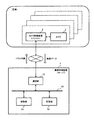
- FIG. 1 is a block diagram showing the configuration of an imaging control apparatus according to first and second embodiments.
- the flowchart which shows the determination of the parameter in 1st Embodiment Flow chart showing calculation of image quality evaluation value Illustration for explaining feature vectors Flowchart showing determination of parameters in the second embodiment Flow chart showing parameter vector generation by genetic algorithm Flow chart showing generation of next generation parameter vector Flow chart for explaining crossover Flowchart explaining the mutation Flow chart for explaining copying
- the camera installation status includes the camera installation position and the lighting conditions of the surrounding environment.
- the parameter group related to the shooting operation of the camera includes a plurality of types of parameters for setting the exposure time, focus, compression quality, and the like.
- hundreds of surveillance cameras may be installed in facilities such as airports and shopping centers or in towns. For such a large number of surveillance cameras, it takes time to manually determine the camera parameter group one by one in accordance with the installation position of the camera and the lighting conditions of the surrounding environment. In addition, when the position of a camera once installed is changed according to the layout change, it is not easy to manually reset the parameter group if the number of cameras is large.
- the present disclosure provides (I) an imaging control apparatus that determines a plurality of types of parameters related to the shooting operation of the camera to appropriate values according to the installation position of the camera, the illumination conditions of the surrounding environment, and the like.
- Patent Document 1 performs focus control based on the contrast of a region to be focused on in a captured image.
- the contrast is improved by increasing the shutter speed, the brightness level is lowered.
- the contrast is lowered due to motion blur. Therefore, when only the contrast is used as an index, the luminance level is not taken into account, and there is a possibility of adversely affecting face recognition. Therefore, contrast is not always an index suitable for face recognition.
- Patent Document 2 realizes brightness adjustment of a captured image by a method of bringing a luminance level close to a target value.
- the brightness level is not always an appropriate index for face recognition.
- how to set the target value is not clearly defined. That is, a target value suitable for face recognition is not set.
- This disclosure provides (II) an imaging control device that determines a parameter group suitable for face recognition.
- an imaging control apparatus determines (I) a parameter having an appropriate value according to the installation position of the camera and lighting conditions of the surrounding environment, and (II) a parameter suitable for face recognition.
- the imaging control device calculates an image quality evaluation value based on a feature amount of a face image from a moving image captured by a camera such as a surveillance camera, and sets a parameter group to be set in the camera based on the image quality evaluation value. decide.
- a parameter group suitable for face recognition can be set in the camera according to the installation position of the camera and the illumination conditions of the surrounding environment. Therefore, the face recognition performance is improved.
- FIG. 1 illustrates an electrical configuration of the imaging control device of the present disclosure.
- the imaging control device 1 is a server
- the camera 2 is a surveillance camera
- the camera control device 3 is a personal computer.
- the imaging control apparatus 1 is a cloud server, for example, and is connected to one or more camera control apparatuses 3 via the Internet.
- one camera 2 is connected to one camera control device 3.
- the imaging control device 1 determines a parameter group for each of the plurality of cameras 2.
- the imaging control device 1 includes a communication unit 10, a control unit 20, a storage unit 30, and a bus 40.
- the communication unit 10 includes a circuit that performs communication with an external device in accordance with a predetermined communication standard.
- the predetermined communication standard includes, for example, LAN, Wi-Fi (registered trademark), Bluetooth (registered trademark), USB, and HDMI (registered trademark).
- the control unit 20 controls the operation of the imaging control device 1.
- the control unit 20 can be realized by a semiconductor element or the like.
- the control unit 20 can be configured by, for example, a microcomputer, CPU, MPU, DSP, FPGA, and ASIC.
- the function of the control unit 20 may be configured only by hardware, or may be realized by combining hardware and software.
- the control unit 20 reads out data and programs stored in the storage unit 30 and performs various arithmetic processes to realize predetermined functions.
- the program executed by the control unit 20 may be provided from the communication unit 10 or the like, or may be stored in a portable recording medium.
- the control unit 20 determines a parameter group related to the shooting operation of the camera 2 based on the imaging data generated by the camera 2.
- the parameter group of the camera 2 includes a plurality of types of parameters that affect the image quality.
- the parameter group includes one or more of an aperture value, gain, white balance, shutter speed, and focal length.
- the storage unit 30 can be realized by, for example, a hard disk (HDD), SSD, RAM, DRAM, ferroelectric memory, flash memory, magnetic disk, or a combination thereof.
- HDD hard disk
- SSD SSD
- RAM random access memory
- DRAM dynamic random access memory
- ferroelectric memory ferroelectric memory
- flash memory magnetic disk, or a combination thereof.
- the bus 40 is a signal line that electrically connects the communication unit 10, the control unit 20, and the storage unit 30.
- the imaging control device 1 may further include a user interface for inputting various operations by the user.
- the imaging control device 1 may include a keyboard, buttons, switches, and combinations thereof.
- the camera 2 includes an image sensor such as a CCD image sensor, a CMOS image sensor, or an NMOS image sensor.
- the camera control device 3 sets the camera 2 based on the parameter group determined by the imaging control device 1.
- FIG. 2 is a flowchart illustrating an operation of determining a parameter vector by the control unit 20 of the imaging control apparatus 1.
- the parameter vector p i is a parameter group including a plurality of parameters.
- each parameter vector p i includes parameters p i, 1 , p i, 2 , p i, 3 ... P i, M which are M elements.
- Each parameter pi , 1 , pi, 2, pi, 3 ... Pi, M corresponds to an aperture value, gain, white balance, shutter speed, focal length, and the like.
- the T parameter vectors p i constitutes a parameter vector p i of T pattern.
- one or more of the elements included in the parameter vector p i is has a value different from the same type of elements included in the other parameters vector p i.
- at least one of an aperture value, gain, white balance, shutter speed, and focal length is different.
- the generation method of T parameter vectors p i is arbitrary.
- T parameter vectors p i may be generated by all combinations of settable values.
- the T parameter vectors p i generated in step S1 the final parameter group of candidates to be set in the camera 2.
- the control unit 20 calculates an image quality evaluation value a i for the parameter vector p i (S2).
- the image quality evaluation value a i in this embodiment relates to image recognition, and specifically corresponds to the degree of suitability for face recognition.
- the control unit 20 determines whether or not the calculated image quality evaluation value a i is the maximum among the already calculated image quality evaluation values (S3). If the image quality evaluation value a i is the maximum, the parameter vector p i is determined as the optimum parameter vector p opt (S4). If the image quality evaluation value a i is not the maximum, step S4 is skipped.
- the control unit 20 determines whether or not the evaluation based on the image quality evaluation value a i has been completed for all of the T parameter vectors p i (S5). If there is the parameter vector p i which is not evaluated, the flow returns to step S2.
- the parameter vector p opt is output to the camera control device 3 as an optimal camera parameter (S6).
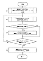
- FIG. 3 shows details of image quality evaluation value calculation (S2).
- the control unit 20 sets the various parameters of the camera 2 by outputting the parameter vector pi to the camera control device 3 (S201).
- Control unit 20 a camera 2 which is set to the value indicated by the parameter vector p i is acquiring imaging data generated by photographing (S202).
- the imaging data is, for example, a moving image including one or more images.
- the control unit 20 extracts N face images from the imaging data (S203). The method for extracting the face image is arbitrary.
- the control unit 20 calculates the image quality evaluation value a i using the N face images (S204). For example, the image quality evaluation value a i is calculated based on the feature amounts of N face images.
- the control unit 20 records the parameter vector p i and the image quality evaluation value a i in the storage unit 30 in association with each other.
- FIG. 4 shows an example of calculating a feature vector v i, j that is an example of a feature amount of a face image.
- a feature vector v i, j 1, 2,..., N
- the neural network is learned in advance by associating learning data indicating a large number of face images with a label indicating who the face image is.
- the learned neural network is stored in the storage unit 30.
- the neural network has a multilayer structure used for deep learning.
- the neural network includes an input layer L1, intermediate layers L2, L3, L4, and an output layer L5.
- the number of intermediate layers is not limited to three.
- the intermediate layer includes one or more layers.
- the neural network outputs a vector indicating who the face image input to the input layer L1 is from the output layer L5.
- the control unit 20 sequentially inputs the first to Nth face images extracted in step S203 to the input layer L1 of the neural network.
- Control unit 20 calculates the image quality evaluation value a i of the N face image as shown in equation (2), the average value of j as an image quality evaluation value a i of the parameter vector p i.
- the imaging control apparatus 1 determines a parameter group related to the imaging operation of the camera 2.
- the imaging control apparatus 1 includes a communication unit 10 that inputs imaging data generated by the camera 2, a control unit 20 that selects a parameter group to be set in the camera from a plurality of parameter group candidates based on the imaging data, and Is provided.
- the control unit 20 acquires imaging data generated by the camera set for each candidate parameter group via the input unit, extracts a plurality of face images from the imaging data for each candidate, and a plurality of face images for each candidate
- the image quality evaluation value is calculated based on the image quality evaluation value, and any one parameter group is selected from a plurality of parameter group candidates based on the image quality evaluation value.
- the parameter group based on the imaging data of the camera 2, it is possible to select a parameter value according to the installation position of the camera 2 and the illumination conditions of the surrounding environment. Therefore, for example, when installing several hundred surveillance cameras in facilities such as airports and shopping centers, the parameter values of each camera are set according to the installation position of the camera 2 and the lighting conditions of the surrounding environment. Therefore, it is not necessary to determine the parameter, so that the operation cost due to parameter adjustment can be reduced.
- the parameter group to be set in the camera 2 is determined based on the image quality evaluation value indicating the degree of suitability for the face recognition calculated from the imaging data of the camera 2. Therefore, the face recognition performance is improved.
- the control unit 20 selects a parameter group of image quality evaluation values that is the maximum among the image quality evaluation values for each candidate. Thereby, the optimal parameter group can be selected according to the installation position of the camera 2 and the illumination conditions of the surrounding environment. In addition, a parameter group optimal for face recognition can be selected. For example, when a face is erroneously detected, the image quality evaluation value is low. Therefore, it is possible to prevent selection of a parameter group in which a face is erroneously detected.
- the control unit 20 calculates the image quality evaluation value by calculating the L2 norm of the feature amounts of the plurality of face images. There is a relationship between the L2 norm of the feature amount of the face image and the image quality. Therefore, by selecting a parameter group based on the image quality evaluation value calculated by the L2 norm of the feature amount of the face image, a parameter group suitable for face recognition according to the installation position of the camera 2 and the illumination conditions of the surrounding environment is obtained. You can choose.
- the method of generating (S1) T parameter vectors is arbitrary.
- T parameter vectors are generated using a genetic algorithm (GA).
- FIG. 5 is a flowchart illustrating an operation of determining a parameter vector by the control unit 20 of the imaging control apparatus 1 in the second embodiment.
- S11 a genetic algorithm
- 5 is the same as FIG. 2 of the first embodiment except that the parameter vector p i is generated by a genetic algorithm. That is, steps S12 to S16 in FIG. 5 are the same as steps S2 to S6 in FIG.
- the control unit 20 determines whether or not the calculation of the image quality evaluation value a g_i has been completed for the T parameter vectors p g_i of the current generation (S113). If it is not completed the calculation of the image quality evaluation value a g_i for T number of the parameter vector p g_i of the current generation, the flow returns to step S112.
- the control unit 20 determines the next T of the next generation based on the T image quality evaluation values a g_i of the current generation.
- the control unit 20 determines whether or not generation of the next generation T parameter vectors pg + 1_i is completed (S115). Step S114 is repeated until the next-generation parameter vector pg + 1_i reaches T.
- the control unit 20 determines whether or not the current generation has reached the final generation (S117). Steps S112 to S117 are repeated until the final generation is reached.
- the control unit 20 stores the T parameter vectors pg_i of the final generation obtained in step S116 in the storage unit 30 (S118). As a result, T parameter vectors having the highest image quality evaluation value in the current generation are finally obtained as solutions of the genetic algorithm.
- FIG. 7 shows details of generation (S114) of T parameter vectors pg + 1_i for the next generation.
- the control unit 20 determines a method for generating the parameter vector pg + 1_i from crossover, mutation, and copy with a certain probability (S1141).
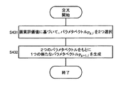
- FIG. 8 is a flowchart showing details of the crossover (S1143).
- the control unit 20 selects two parameter vectors pg_i based on the T image quality evaluation values ag_i calculated in step S112 (S431).
- the parameter vector pg_i is selected by, for example, roulette selection. Specifically, the probability r i of selecting the parameter vector p g_i is calculated by the equation (3) based on the image quality evaluation value a g_i . Based on the probability r i , a parameter vector pg_i is selected.
- the selection of the parameter vector pg_i may be performed by ranking selection. For example, the probability of rank is determined in advance such as probability r 1 for the first place, probability r 2 for the second place, probability r 3 for the third place, and the like. Based on the T image quality evaluation values a g_i , the T parameter vectors pg_i are ranked, and the parameter vector pg_i is selected based on the probability corresponding to the ranking.
- Control unit 20 generates one new parameter vector p g + 1_i based on two parameters vector p g_i (S432). For example, by replacing 1/2 of the probability of two parameters each element of the vector p g_i independently to produce a parameter vector p g + 1_i.
- FIG. 9 is a flowchart showing details of the mutation (S1144).
- the control unit 20 selects one parameter vector pg_i based on the T image quality evaluation values ag_i calculated in step S112 (S441).
- the parameter vector pg_i is selected by, for example, roulette selection or ranking selection described above.
- Control unit 20 generates one new parameter vector p g + 1_i adding changes to each element of the parameter vector p g_i selected (S442). For example, each element of the parameter vector pg_i is randomly changed. Specifically, for example, by replacing the value which is prepared random or pre-probability of 0.1% independently of each element of the parameter vector p g_i, it generates a parameter vector p g + 1_i.
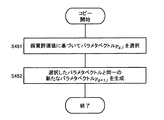
- FIG. 10 is a flowchart showing details of the copy (S1145).
- the control unit 20 selects one parameter vector pg_i based on the T image quality evaluation values ag_i calculated in step S112 (S451).
- the parameter vector pg_i is selected by, for example, roulette selection or ranking selection described above.
- Control unit 20 generates a new parameter vector p g + 1_i the same parameter vector p g_i selected (S452).
- the T parameter vectors p 1 , p 2 , p 3 ,..., P T generated in step S11 are parameter vectors having high image quality evaluation values. Therefore, a parameter vector having a higher image quality evaluation value can be selected by selecting one parameter vector in steps S12 to S15.
- the L2 norm of the feature vector is used as an example of determining a parameter suitable for face recognition using deep learning in the calculation of the image quality evaluation value (S204).
- the image quality evaluation value calculation method is not limited to the above embodiment.
- the image quality evaluation value may be calculated by a function having a feature vector as an input value.
- the image quality evaluation value calculation method may be changed according to the face recognition method.
- Some face recognition methods use a Gabor filter (see “Statistical methods for face detection / face recognition”, Takio Kurita, National Institute of Advanced Industrial Science and Technology (AIST)). In this case, the image quality evaluation value may be calculated based on the Gabor feature amount.
- the Gabor feature value is a feature value based on a specific frequency component in a specific direction, which can be calculated using a Gabor filter.
- This Gabor feature is known to be affected by noise (eg, 22nd Fuzzy System Symposium, Sapporo, September 6-8, 2006, “Cracks on concrete structures using Gabor filters. See “Research on Extraction”).
- the Gabor feature is influenced by blurring (see “21st Image Sensing Symposium, Yokohama, June 2015,“ Study on blur region detection using Gabor filter ”). Therefore, it is considered that there is a correlation between the image quality evaluation value based on the Gabor feature amount of the face image and the face recognition performance.
- the feature vector v i, j (v i, j, 1 , v) of the j-th (1, 2,..., N) face image. i, j, 2 , v i, j, 3 ,..., v i, j, D ), the sum of the elements corresponding to a specific frequency is determined as the image quality evaluation value a i, j of the j th face image . j .
- one camera control device 3 is connected to one camera 2, but a plurality of cameras 2 may be connected to one camera control device 3.
- the number of camera control devices 3 connected to the imaging control device 1 may be one or more.
- parameter determination is performed by the imaging control device 1 such as a server
- parameter setting to the camera 2 is performed by the camera control device 3 such as a personal computer.
- the imaging control device 1 and the camera control device are described.
- the three functions may be performed by one device.
- the imaging control device 1 generates T parameter vectors p i (S1 and S11), but a person may generate T parameter vectors p i .
- the camera control device 3 sets the camera 2 based on the parameter vector p i received from the imaging control device 1. However, a person may set some or all of the parameters of the camera 2.
- the parameter group to be determined may not be suitable for face recognition.
- the image extracted in step S203 is not limited to a face image.
- the feature vector is not limited to the one indicating the feature amount of the face image.
- the image to be extracted and the feature amount may be changed according to the object to be automatically recognized. For example, when determining a parameter group suitable for automatic recognition of a car, the image to be extracted is a car image, and a neural network that has learned the car image is used to generate a feature vector indicating the car feature amount. May be.
- An imaging control apparatus determines a parameter group related to a shooting operation of a camera, and includes an input unit that inputs imaging data generated by the camera and a parameter group based on the imaging data.
- a control unit that selects a parameter group set in the camera from a plurality of candidates, and the control unit acquires imaging data generated by the camera set in the parameter group of each candidate via the input unit,
- a plurality of extraction target images each including an extraction target are extracted from the imaging data for each candidate, an image quality evaluation value is calculated based on the plurality of extraction target images for each candidate, and a plurality of parameter groups are calculated based on the image quality evaluation value. Select one parameter group from the candidates.
- the parameter group based on the imaging data of the camera 2, it is possible to select a parameter value according to the installation position of the camera 2 and the illumination conditions of the surrounding environment. Further, since it is not necessary for a person to adjust the parameter value, the work cost can be reduced.
- control unit may select a parameter group of image quality evaluation values that is the maximum among image quality evaluation values for each candidate.
- the extraction target may be a human face
- the image quality evaluation value may correspond to the degree of suitability for face recognition
- control unit may generate a plurality of parameter group candidates using a genetic algorithm.
- control unit may calculate the image quality evaluation value by calculating the L2 norm of the feature amount of the plurality of extraction target images.
- control unit may calculate the image quality evaluation value by calculating the Gabor feature amount of the plurality of extraction target images.
- the parameter group may include at least two of an aperture value, a gain, a white balance, a shutter speed, and a focal length.
- the imaging control method is an imaging control method in which a calculation unit determines a parameter group related to a shooting operation of a camera, and imaging data generated by a camera set in each of a plurality of parameter group candidates Is extracted via the input unit, a plurality of extraction target images each including the extraction target are extracted from the imaging data for each candidate, and an image quality evaluation value is calculated based on the plurality of extraction target images for each candidate. Based on the above, a parameter group to be set in the camera is selected from among a plurality of parameter group candidates.
- the imaging control device and the imaging control method described in all claims of the present disclosure are realized by cooperation with hardware resources, for example, a processor, a memory, and a program.
- the imaging control device of the present disclosure is useful for setting the parameters of a surveillance camera, for example.
Landscapes
- Engineering & Computer Science (AREA)
- Multimedia (AREA)
- General Physics & Mathematics (AREA)
- Theoretical Computer Science (AREA)
- Physics & Mathematics (AREA)
- Health & Medical Sciences (AREA)
- General Health & Medical Sciences (AREA)
- Quality & Reliability (AREA)
- Signal Processing (AREA)
- Evolutionary Computation (AREA)
- Human Computer Interaction (AREA)
- Computer Vision & Pattern Recognition (AREA)
- Oral & Maxillofacial Surgery (AREA)
- Software Systems (AREA)
- Vascular Medicine (AREA)
- Artificial Intelligence (AREA)
- Computing Systems (AREA)
- Databases & Information Systems (AREA)
- Medical Informatics (AREA)
- Studio Devices (AREA)
- Exposure Control For Cameras (AREA)
- Image Analysis (AREA)
Priority Applications (4)
| Application Number | Priority Date | Filing Date | Title |
|---|---|---|---|
| JP2020525330A JP7246029B2 (ja) | 2018-06-11 | 2019-05-07 | 撮像制御装置、撮像制御方法、及びプログラム |
| EP19818508.4A EP3806447A4 (en) | 2018-06-11 | 2019-05-07 | IMAGING CONTROL DEVICE, IMAGING CONTROL PROCESS, AND PROGRAM |
| CN201980038771.0A CN112272945A (zh) | 2018-06-11 | 2019-05-07 | 摄像控制装置、摄像控制方法以及程序 |
| US17/108,294 US20210112191A1 (en) | 2018-06-11 | 2020-12-01 | Imaging control device, imaging control method, and non-transitory computer-readable recording medium |
Applications Claiming Priority (2)
| Application Number | Priority Date | Filing Date | Title |
|---|---|---|---|
| JP2018111389 | 2018-06-11 | ||
| JP2018-111389 | 2018-06-11 |
Related Child Applications (1)
| Application Number | Title | Priority Date | Filing Date |
|---|---|---|---|
| US17/108,294 Continuation US20210112191A1 (en) | 2018-06-11 | 2020-12-01 | Imaging control device, imaging control method, and non-transitory computer-readable recording medium |
Publications (1)
| Publication Number | Publication Date |
|---|---|
| WO2019239744A1 true WO2019239744A1 (ja) | 2019-12-19 |
Family
ID=68843180
Family Applications (1)
| Application Number | Title | Priority Date | Filing Date |
|---|---|---|---|
| PCT/JP2019/018270 Ceased WO2019239744A1 (ja) | 2018-06-11 | 2019-05-07 | 撮像制御装置、撮像制御方法、及びプログラム |
Country Status (5)
| Country | Link |
|---|---|
| US (1) | US20210112191A1 (https=) |
| EP (1) | EP3806447A4 (https=) |
| JP (1) | JP7246029B2 (https=) |
| CN (1) | CN112272945A (https=) |
| WO (1) | WO2019239744A1 (https=) |
Families Citing this family (1)
| Publication number | Priority date | Publication date | Assignee | Title |
|---|---|---|---|---|
| JP7631289B2 (ja) * | 2022-11-29 | 2025-02-18 | キヤノン株式会社 | データ処理装置及びその方法 |
Citations (8)
| Publication number | Priority date | Publication date | Assignee | Title |
|---|---|---|---|---|
| JPS4921204B1 (https=) | 1970-12-22 | 1974-05-30 | ||
| JPS5829679B2 (ja) | 1977-03-01 | 1983-06-24 | 日本電気株式会社 | 時分割通話路制御方式 |
| JP2008191816A (ja) * | 2007-02-02 | 2008-08-21 | Sony Corp | 画像処理装置、および画像処理方法、並びにコンピュータ・プログラム |
| US20140148690A1 (en) * | 2012-11-26 | 2014-05-29 | Samsung Electronics Co., Ltd. | Method and apparatus for medical image registration |
| JP2016537912A (ja) * | 2013-10-30 | 2016-12-01 | インテル コーポレイション | 画像キャプチャフィードバック |
| JP2017224025A (ja) * | 2016-06-13 | 2017-12-21 | 株式会社キーエンス | 画像処理センサ及び画像処理方法 |
| JP2018005574A (ja) * | 2016-07-01 | 2018-01-11 | キヤノン株式会社 | 画像処理装置、画像処理装置の制御方法およびプログラム |
| JP2018088233A (ja) * | 2016-11-24 | 2018-06-07 | 株式会社リコー | 情報処理装置、撮像装置、機器制御システム、移動体、情報処理方法、及びプログラム |
Family Cites Families (9)
| Publication number | Priority date | Publication date | Assignee | Title |
|---|---|---|---|---|
| US7616233B2 (en) * | 2003-06-26 | 2009-11-10 | Fotonation Vision Limited | Perfecting of digital image capture parameters within acquisition devices using face detection |
| JP2007094535A (ja) * | 2005-09-27 | 2007-04-12 | Konica Minolta Photo Imaging Inc | 認証システム及び認証方法 |
| WO2007119355A1 (ja) * | 2006-03-15 | 2007-10-25 | Omron Corporation | 追尾装置、追尾方法、追尾装置の制御プログラム、およびコンピュータ読み取り可能な記録媒体 |
| US8111942B2 (en) * | 2008-02-06 | 2012-02-07 | O2Micro, Inc. | System and method for optimizing camera settings |
| JP5424819B2 (ja) * | 2009-11-04 | 2014-02-26 | キヤノン株式会社 | 画像処理装置、画像処理方法 |
| JP5958716B2 (ja) * | 2012-01-30 | 2016-08-02 | パナソニックIpマネジメント株式会社 | 最適カメラ設定装置及び最適カメラ設定方法 |
| JP6347589B2 (ja) * | 2013-10-30 | 2018-06-27 | キヤノン株式会社 | 情報処理装置、情報処理方法及びプログラム |
| CN104270566B (zh) * | 2014-09-01 | 2018-09-07 | 深圳市思谋科技有限公司 | 摄像直读抄表装置、系统、提高读数识别率的方法和装置 |
| CN107977674B (zh) * | 2017-11-21 | 2020-02-18 | Oppo广东移动通信有限公司 | 图像处理方法、装置、移动终端及计算机可读存储介质 |
-
2019
- 2019-05-07 JP JP2020525330A patent/JP7246029B2/ja active Active
- 2019-05-07 CN CN201980038771.0A patent/CN112272945A/zh active Pending
- 2019-05-07 WO PCT/JP2019/018270 patent/WO2019239744A1/ja not_active Ceased
- 2019-05-07 EP EP19818508.4A patent/EP3806447A4/en not_active Withdrawn
-
2020
- 2020-12-01 US US17/108,294 patent/US20210112191A1/en not_active Abandoned
Patent Citations (8)
| Publication number | Priority date | Publication date | Assignee | Title |
|---|---|---|---|---|
| JPS4921204B1 (https=) | 1970-12-22 | 1974-05-30 | ||
| JPS5829679B2 (ja) | 1977-03-01 | 1983-06-24 | 日本電気株式会社 | 時分割通話路制御方式 |
| JP2008191816A (ja) * | 2007-02-02 | 2008-08-21 | Sony Corp | 画像処理装置、および画像処理方法、並びにコンピュータ・プログラム |
| US20140148690A1 (en) * | 2012-11-26 | 2014-05-29 | Samsung Electronics Co., Ltd. | Method and apparatus for medical image registration |
| JP2016537912A (ja) * | 2013-10-30 | 2016-12-01 | インテル コーポレイション | 画像キャプチャフィードバック |
| JP2017224025A (ja) * | 2016-06-13 | 2017-12-21 | 株式会社キーエンス | 画像処理センサ及び画像処理方法 |
| JP2018005574A (ja) * | 2016-07-01 | 2018-01-11 | キヤノン株式会社 | 画像処理装置、画像処理装置の制御方法およびプログラム |
| JP2018088233A (ja) * | 2016-11-24 | 2018-06-07 | 株式会社リコー | 情報処理装置、撮像装置、機器制御システム、移動体、情報処理方法、及びプログラム |
Non-Patent Citations (4)
| Title |
|---|
| "Recognition of Cracks in Concrete Structures Using Gabor Function", 22ND FUZZY SYSTEM SYMPOSIUM, 6 September 2006 (2006-09-06) |
| "Research on Blurred Region Detection Using Gabor Filter", THE 22TH SYMPOSIUM ON SENSING VIA IMAGE INFORMATION, June 2015 (2015-06-01) |
| See also references of EP3806447A4 |
| TAKIO KURITA: "Neuroscience Research Institute", NATIONAL INSTITUTE OF ADVANCED INDUSTRIAL SCIENCE AND TECHNOLOGY, article "Statistical Method for Face Detection/Face Recognition" |
Also Published As
| Publication number | Publication date |
|---|---|
| EP3806447A4 (en) | 2021-07-14 |
| CN112272945A (zh) | 2021-01-26 |
| US20210112191A1 (en) | 2021-04-15 |
| JP7246029B2 (ja) | 2023-03-27 |
| JPWO2019239744A1 (ja) | 2021-08-26 |
| EP3806447A1 (en) | 2021-04-14 |
Similar Documents
| Publication | Publication Date | Title |
|---|---|---|
| US11089228B2 (en) | Information processing apparatus, control method of information processing apparatus, storage medium, and imaging system | |
| US12165358B2 (en) | Main subject determining apparatus, image capturing apparatus, main subject determining method, and storage medium | |
| JP2015033103A (ja) | 画像処理装置、画像処理方法、およびプログラム | |
| US20140286544A1 (en) | Method and apparatus for optical fingerprint recognition using multiple exposure | |
| KR20190016900A (ko) | 정보 처리장치, 정보 처리방법 및 기억매체 | |
| US11397874B2 (en) | Image capturing apparatus, generating apparatus, control method, and storage medium | |
| JP7353864B2 (ja) | 情報処理装置、情報処理装置の制御方法およびプログラム、撮像システム | |
| US11587324B2 (en) | Control apparatus, control method, storage medium, and imaging control system | |
| US20200045242A1 (en) | Display control device, display control method, and program | |
| JP2018084861A (ja) | 情報処理装置、情報処理方法、及び情報処理プログラム | |
| JP2015138399A (ja) | 画像処理装置、画像処理方法、及びコンピュータプログラム | |
| JP7246029B2 (ja) | 撮像制御装置、撮像制御方法、及びプログラム | |
| JP5118590B2 (ja) | 被写体追尾方法及び撮像装置 | |
| CN107124547A (zh) | 双摄像头拍照方法及装置 | |
| EP3883236B1 (en) | Information processing apparatus, imaging apparatus, method, and storage medium | |
| CN110933304B (zh) | 待虚化区域的确定方法、装置、存储介质与终端设备 | |
| US12307819B2 (en) | Identification model generation apparatus, identification apparatus, identification model generation method, identification method, and storage medium | |
| CN109218620B (zh) | 基于环境亮度的拍照方法、装置、存储介质及移动终端 | |
| JP6071714B2 (ja) | 画像処理装置、およびその制御方法 | |
| CN117716703A (zh) | 低光条件下的计算摄影 | |
| US11711619B2 (en) | Controlling exposure based on inverse gamma characteristic | |
| CN114979607B (zh) | 图像处理方法、图像处理器及电子设备 | |
| WO2022269999A1 (ja) | 制御装置、制御方法、およびプログラム | |
| JP2022138367A (ja) | 画像処理装置、画像処理方法、及びプログラム | |
| JP2024153137A (ja) | 情報処理装置、パラメータ調整方法及びプログラム |
Legal Events
| Date | Code | Title | Description |
|---|---|---|---|
| 121 | Ep: the epo has been informed by wipo that ep was designated in this application |
Ref document number: 19818508 Country of ref document: EP Kind code of ref document: A1 |
|
| DPE1 | Request for preliminary examination filed after expiration of 19th month from priority date (pct application filed from 20040101) | ||
| ENP | Entry into the national phase |
Ref document number: 2020525330 Country of ref document: JP Kind code of ref document: A |
|
| NENP | Non-entry into the national phase |
Ref country code: DE |
|
| ENP | Entry into the national phase |
Ref document number: 2019818508 Country of ref document: EP Effective date: 20210111 |