WO2019239744A1 - 撮像制御装置、撮像制御方法、及びプログラム - Google Patents
撮像制御装置、撮像制御方法、及びプログラム Download PDFInfo
- Publication number
- WO2019239744A1 WO2019239744A1 PCT/JP2019/018270 JP2019018270W WO2019239744A1 WO 2019239744 A1 WO2019239744 A1 WO 2019239744A1 JP 2019018270 W JP2019018270 W JP 2019018270W WO 2019239744 A1 WO2019239744 A1 WO 2019239744A1
- Authority
- WO
- WIPO (PCT)
- Prior art keywords
- camera
- parameter group
- image quality
- quality evaluation
- imaging
- Prior art date
Links
Images


Classifications
-
- G—PHYSICS
- G03—PHOTOGRAPHY; CINEMATOGRAPHY; ANALOGOUS TECHNIQUES USING WAVES OTHER THAN OPTICAL WAVES; ELECTROGRAPHY; HOLOGRAPHY
- G03B—APPARATUS OR ARRANGEMENTS FOR TAKING PHOTOGRAPHS OR FOR PROJECTING OR VIEWING THEM; APPARATUS OR ARRANGEMENTS EMPLOYING ANALOGOUS TECHNIQUES USING WAVES OTHER THAN OPTICAL WAVES; ACCESSORIES THEREFOR
- G03B7/00—Control of exposure by setting shutters, diaphragms or filters, separately or conjointly
- G03B7/08—Control effected solely on the basis of the response, to the intensity of the light received by the camera, of a built-in light-sensitive device
- G03B7/091—Digital circuits
-
- G—PHYSICS
- G06—COMPUTING; CALCULATING OR COUNTING
- G06T—IMAGE DATA PROCESSING OR GENERATION, IN GENERAL
- G06T7/00—Image analysis
- G06T7/0002—Inspection of images, e.g. flaw detection
-
- G—PHYSICS
- G06—COMPUTING; CALCULATING OR COUNTING
- G06V—IMAGE OR VIDEO RECOGNITION OR UNDERSTANDING
- G06V10/00—Arrangements for image or video recognition or understanding
- G06V10/10—Image acquisition
- G06V10/12—Details of acquisition arrangements; Constructional details thereof
- G06V10/14—Optical characteristics of the device performing the acquisition or on the illumination arrangements
- G06V10/147—Details of sensors, e.g. sensor lenses
-
- G—PHYSICS
- G06—COMPUTING; CALCULATING OR COUNTING
- G06V—IMAGE OR VIDEO RECOGNITION OR UNDERSTANDING
- G06V10/00—Arrangements for image or video recognition or understanding
- G06V10/70—Arrangements for image or video recognition or understanding using pattern recognition or machine learning
- G06V10/82—Arrangements for image or video recognition or understanding using pattern recognition or machine learning using neural networks
-
- G—PHYSICS
- G06—COMPUTING; CALCULATING OR COUNTING
- G06V—IMAGE OR VIDEO RECOGNITION OR UNDERSTANDING
- G06V10/00—Arrangements for image or video recognition or understanding
- G06V10/98—Detection or correction of errors, e.g. by rescanning the pattern or by human intervention; Evaluation of the quality of the acquired patterns
- G06V10/993—Evaluation of the quality of the acquired pattern
-
- G—PHYSICS
- G06—COMPUTING; CALCULATING OR COUNTING
- G06V—IMAGE OR VIDEO RECOGNITION OR UNDERSTANDING
- G06V40/00—Recognition of biometric, human-related or animal-related patterns in image or video data
- G06V40/10—Human or animal bodies, e.g. vehicle occupants or pedestrians; Body parts, e.g. hands
- G06V40/16—Human faces, e.g. facial parts, sketches or expressions
- G06V40/161—Detection; Localisation; Normalisation
- G06V40/166—Detection; Localisation; Normalisation using acquisition arrangements
-
- G—PHYSICS
- G06—COMPUTING; CALCULATING OR COUNTING
- G06V—IMAGE OR VIDEO RECOGNITION OR UNDERSTANDING
- G06V40/00—Recognition of biometric, human-related or animal-related patterns in image or video data
- G06V40/10—Human or animal bodies, e.g. vehicle occupants or pedestrians; Body parts, e.g. hands
- G06V40/16—Human faces, e.g. facial parts, sketches or expressions
- G06V40/172—Classification, e.g. identification
-
- H—ELECTRICITY
- H04—ELECTRIC COMMUNICATION TECHNIQUE
- H04N—PICTORIAL COMMUNICATION, e.g. TELEVISION
- H04N23/00—Cameras or camera modules comprising electronic image sensors; Control thereof
- H04N23/60—Control of cameras or camera modules
- H04N23/61—Control of cameras or camera modules based on recognised objects
- H04N23/611—Control of cameras or camera modules based on recognised objects where the recognised objects include parts of the human body
-
- H—ELECTRICITY
- H04—ELECTRIC COMMUNICATION TECHNIQUE
- H04N—PICTORIAL COMMUNICATION, e.g. TELEVISION
- H04N23/00—Cameras or camera modules comprising electronic image sensors; Control thereof
- H04N23/60—Control of cameras or camera modules
- H04N23/617—Upgrading or updating of programs or applications for camera control
-
- H—ELECTRICITY
- H04—ELECTRIC COMMUNICATION TECHNIQUE
- H04N—PICTORIAL COMMUNICATION, e.g. TELEVISION
- H04N23/00—Cameras or camera modules comprising electronic image sensors; Control thereof
- H04N23/60—Control of cameras or camera modules
- H04N23/62—Control of parameters via user interfaces
-
- H—ELECTRICITY
- H04—ELECTRIC COMMUNICATION TECHNIQUE
- H04N—PICTORIAL COMMUNICATION, e.g. TELEVISION
- H04N23/00—Cameras or camera modules comprising electronic image sensors; Control thereof
- H04N23/60—Control of cameras or camera modules
- H04N23/68—Control of cameras or camera modules for stable pick-up of the scene, e.g. compensating for camera body vibrations
- H04N23/682—Vibration or motion blur correction
- H04N23/683—Vibration or motion blur correction performed by a processor, e.g. controlling the readout of an image memory
-
- G—PHYSICS
- G06—COMPUTING; CALCULATING OR COUNTING
- G06T—IMAGE DATA PROCESSING OR GENERATION, IN GENERAL
- G06T2207/00—Indexing scheme for image analysis or image enhancement
- G06T2207/30—Subject of image; Context of image processing
- G06T2207/30168—Image quality inspection
-
- G—PHYSICS
- G06—COMPUTING; CALCULATING OR COUNTING
- G06T—IMAGE DATA PROCESSING OR GENERATION, IN GENERAL
- G06T2207/00—Indexing scheme for image analysis or image enhancement
- G06T2207/30—Subject of image; Context of image processing
- G06T2207/30196—Human being; Person
- G06T2207/30201—Face
Definitions
- the present disclosure relates to an imaging control apparatus, an imaging control method, and a program that determine parameters relating to a shooting operation of a camera.
- Patent Document 1 discloses an imaging apparatus that focuses using a contrast method.
- This imaging apparatus includes an image to be searched for a case where a combination of a subject image region and a partial image region of the same person is searched, and a region detected after a combination of the subject image region and the partial image region is detected. Different search conditions suitable for each search are used. Searching the subject image area and the partial image area in combination prevents the detection of a person from being detected. It is improving. Improvement of the detection rate leads to stabilization of the focus search area. Thereby, the stability of the focus control in the case of focusing by the contrast method is improved.
- Patent Document 2 discloses an imaging device that images a monitoring target.
- This image pickup apparatus has an automatic exposure control means for changing the brightness value of the output signal of the image pickup device to the target value by changing the value of the operating parameter including at least one of the aperture value and the shutter speed and the gain value.
- Automatic exposure control means that when the aperture value is set to a predetermined value close to the end of the small aperture and the brightness of the monitored object becomes dark, the aperture is set when the abnormal monitoring mode is set rather than the normal monitoring mode. Change the value in preference. Thereby, the abnormal state is photographed with high image quality and the durability is improved.
- This disclosure provides an imaging control device, an imaging control method, and a program that determine parameters according to the installation status of a camera.
- An imaging control apparatus is an imaging control apparatus that determines a parameter group related to a shooting operation of a camera, and includes an input unit that inputs imaging data generated by the camera, and a plurality of parameter group candidates based on the imaging data
- a control unit that selects a parameter group to be set in the camera from the control unit, the control unit acquires the imaging data generated by the camera set in each candidate parameter group via the input unit, for each candidate
- a plurality of extraction target images each including an extraction target are extracted from the imaging data, and an image quality evaluation value is calculated for each candidate based on the plurality of extraction target images. Select any one parameter group from.
- the parameter group to be set in the camera is determined based on the image quality evaluation value calculated based on the imaging data of the camera. Therefore, it is possible to determine a parameter according to the camera installation status.
- FIG. 1 is a block diagram showing the configuration of an imaging control apparatus according to first and second embodiments.
- the flowchart which shows the determination of the parameter in 1st Embodiment Flow chart showing calculation of image quality evaluation value Illustration for explaining feature vectors Flowchart showing determination of parameters in the second embodiment Flow chart showing parameter vector generation by genetic algorithm Flow chart showing generation of next generation parameter vector Flow chart for explaining crossover Flowchart explaining the mutation Flow chart for explaining copying
- the camera installation status includes the camera installation position and the lighting conditions of the surrounding environment.
- the parameter group related to the shooting operation of the camera includes a plurality of types of parameters for setting the exposure time, focus, compression quality, and the like.
- hundreds of surveillance cameras may be installed in facilities such as airports and shopping centers or in towns. For such a large number of surveillance cameras, it takes time to manually determine the camera parameter group one by one in accordance with the installation position of the camera and the lighting conditions of the surrounding environment. In addition, when the position of a camera once installed is changed according to the layout change, it is not easy to manually reset the parameter group if the number of cameras is large.
- the present disclosure provides (I) an imaging control apparatus that determines a plurality of types of parameters related to the shooting operation of the camera to appropriate values according to the installation position of the camera, the illumination conditions of the surrounding environment, and the like.
- Patent Document 1 performs focus control based on the contrast of a region to be focused on in a captured image.
- the contrast is improved by increasing the shutter speed, the brightness level is lowered.
- the contrast is lowered due to motion blur. Therefore, when only the contrast is used as an index, the luminance level is not taken into account, and there is a possibility of adversely affecting face recognition. Therefore, contrast is not always an index suitable for face recognition.
- Patent Document 2 realizes brightness adjustment of a captured image by a method of bringing a luminance level close to a target value.
- the brightness level is not always an appropriate index for face recognition.
- how to set the target value is not clearly defined. That is, a target value suitable for face recognition is not set.
- This disclosure provides (II) an imaging control device that determines a parameter group suitable for face recognition.
- an imaging control apparatus determines (I) a parameter having an appropriate value according to the installation position of the camera and lighting conditions of the surrounding environment, and (II) a parameter suitable for face recognition.
- the imaging control device calculates an image quality evaluation value based on a feature amount of a face image from a moving image captured by a camera such as a surveillance camera, and sets a parameter group to be set in the camera based on the image quality evaluation value. decide.
- a parameter group suitable for face recognition can be set in the camera according to the installation position of the camera and the illumination conditions of the surrounding environment. Therefore, the face recognition performance is improved.
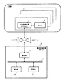
- FIG. 1 illustrates an electrical configuration of the imaging control device of the present disclosure.
- the imaging control device 1 is a server
- the camera 2 is a surveillance camera
- the camera control device 3 is a personal computer.
- the imaging control apparatus 1 is a cloud server, for example, and is connected to one or more camera control apparatuses 3 via the Internet.
- one camera 2 is connected to one camera control device 3.
- the imaging control device 1 determines a parameter group for each of the plurality of cameras 2.
- the imaging control device 1 includes a communication unit 10, a control unit 20, a storage unit 30, and a bus 40.
- the communication unit 10 includes a circuit that performs communication with an external device in accordance with a predetermined communication standard.
- the predetermined communication standard includes, for example, LAN, Wi-Fi (registered trademark), Bluetooth (registered trademark), USB, and HDMI (registered trademark).
- the control unit 20 controls the operation of the imaging control device 1.
- the control unit 20 can be realized by a semiconductor element or the like.
- the control unit 20 can be configured by, for example, a microcomputer, CPU, MPU, DSP, FPGA, and ASIC.
- the function of the control unit 20 may be configured only by hardware, or may be realized by combining hardware and software.
- the control unit 20 reads out data and programs stored in the storage unit 30 and performs various arithmetic processes to realize predetermined functions.
- the program executed by the control unit 20 may be provided from the communication unit 10 or the like, or may be stored in a portable recording medium.
- the control unit 20 determines a parameter group related to the shooting operation of the camera 2 based on the imaging data generated by the camera 2.
- the parameter group of the camera 2 includes a plurality of types of parameters that affect the image quality.
- the parameter group includes one or more of an aperture value, gain, white balance, shutter speed, and focal length.
- the storage unit 30 can be realized by, for example, a hard disk (HDD), SSD, RAM, DRAM, ferroelectric memory, flash memory, magnetic disk, or a combination thereof.
- HDD hard disk
- SSD SSD
- RAM random access memory
- DRAM dynamic random access memory
- ferroelectric memory ferroelectric memory
- flash memory magnetic disk, or a combination thereof.
- the bus 40 is a signal line that electrically connects the communication unit 10, the control unit 20, and the storage unit 30.
- the imaging control device 1 may further include a user interface for inputting various operations by the user.
- the imaging control device 1 may include a keyboard, buttons, switches, and combinations thereof.
- the camera 2 includes an image sensor such as a CCD image sensor, a CMOS image sensor, or an NMOS image sensor.
- the camera control device 3 sets the camera 2 based on the parameter group determined by the imaging control device 1.
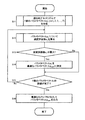
- FIG. 2 is a flowchart illustrating an operation of determining a parameter vector by the control unit 20 of the imaging control apparatus 1.
- the parameter vector p i is a parameter group including a plurality of parameters.
- each parameter vector p i includes parameters p i, 1 , p i, 2 , p i, 3 ... P i, M which are M elements.
- Each parameter pi , 1 , pi, 2, pi, 3 ... Pi, M corresponds to an aperture value, gain, white balance, shutter speed, focal length, and the like.
- the T parameter vectors p i constitutes a parameter vector p i of T pattern.
- one or more of the elements included in the parameter vector p i is has a value different from the same type of elements included in the other parameters vector p i.
- at least one of an aperture value, gain, white balance, shutter speed, and focal length is different.
- the generation method of T parameter vectors p i is arbitrary.
- T parameter vectors p i may be generated by all combinations of settable values.
- the T parameter vectors p i generated in step S1 the final parameter group of candidates to be set in the camera 2.
- the control unit 20 calculates an image quality evaluation value a i for the parameter vector p i (S2).
- the image quality evaluation value a i in this embodiment relates to image recognition, and specifically corresponds to the degree of suitability for face recognition.
- the control unit 20 determines whether or not the calculated image quality evaluation value a i is the maximum among the already calculated image quality evaluation values (S3). If the image quality evaluation value a i is the maximum, the parameter vector p i is determined as the optimum parameter vector p opt (S4). If the image quality evaluation value a i is not the maximum, step S4 is skipped.
- the control unit 20 determines whether or not the evaluation based on the image quality evaluation value a i has been completed for all of the T parameter vectors p i (S5). If there is the parameter vector p i which is not evaluated, the flow returns to step S2.
- the parameter vector p opt is output to the camera control device 3 as an optimal camera parameter (S6).
- FIG. 3 shows details of image quality evaluation value calculation (S2).
- the control unit 20 sets the various parameters of the camera 2 by outputting the parameter vector pi to the camera control device 3 (S201).
- Control unit 20 a camera 2 which is set to the value indicated by the parameter vector p i is acquiring imaging data generated by photographing (S202).
- the imaging data is, for example, a moving image including one or more images.
- the control unit 20 extracts N face images from the imaging data (S203). The method for extracting the face image is arbitrary.
- the control unit 20 calculates the image quality evaluation value a i using the N face images (S204). For example, the image quality evaluation value a i is calculated based on the feature amounts of N face images.
- the control unit 20 records the parameter vector p i and the image quality evaluation value a i in the storage unit 30 in association with each other.
- FIG. 4 shows an example of calculating a feature vector v i, j that is an example of a feature amount of a face image.
- a feature vector v i, j 1, 2,..., N
- the neural network is learned in advance by associating learning data indicating a large number of face images with a label indicating who the face image is.
- the learned neural network is stored in the storage unit 30.
- the neural network has a multilayer structure used for deep learning.
- the neural network includes an input layer L1, intermediate layers L2, L3, L4, and an output layer L5.
- the number of intermediate layers is not limited to three.
- the intermediate layer includes one or more layers.
- the neural network outputs a vector indicating who the face image input to the input layer L1 is from the output layer L5.
- the control unit 20 sequentially inputs the first to Nth face images extracted in step S203 to the input layer L1 of the neural network.
- Control unit 20 calculates the image quality evaluation value a i of the N face image as shown in equation (2), the average value of j as an image quality evaluation value a i of the parameter vector p i.
- the imaging control apparatus 1 determines a parameter group related to the imaging operation of the camera 2.
- the imaging control apparatus 1 includes a communication unit 10 that inputs imaging data generated by the camera 2, a control unit 20 that selects a parameter group to be set in the camera from a plurality of parameter group candidates based on the imaging data, and Is provided.
- the control unit 20 acquires imaging data generated by the camera set for each candidate parameter group via the input unit, extracts a plurality of face images from the imaging data for each candidate, and a plurality of face images for each candidate
- the image quality evaluation value is calculated based on the image quality evaluation value, and any one parameter group is selected from a plurality of parameter group candidates based on the image quality evaluation value.
- the parameter group based on the imaging data of the camera 2, it is possible to select a parameter value according to the installation position of the camera 2 and the illumination conditions of the surrounding environment. Therefore, for example, when installing several hundred surveillance cameras in facilities such as airports and shopping centers, the parameter values of each camera are set according to the installation position of the camera 2 and the lighting conditions of the surrounding environment. Therefore, it is not necessary to determine the parameter, so that the operation cost due to parameter adjustment can be reduced.
- the parameter group to be set in the camera 2 is determined based on the image quality evaluation value indicating the degree of suitability for the face recognition calculated from the imaging data of the camera 2. Therefore, the face recognition performance is improved.
- the control unit 20 selects a parameter group of image quality evaluation values that is the maximum among the image quality evaluation values for each candidate. Thereby, the optimal parameter group can be selected according to the installation position of the camera 2 and the illumination conditions of the surrounding environment. In addition, a parameter group optimal for face recognition can be selected. For example, when a face is erroneously detected, the image quality evaluation value is low. Therefore, it is possible to prevent selection of a parameter group in which a face is erroneously detected.
- the control unit 20 calculates the image quality evaluation value by calculating the L2 norm of the feature amounts of the plurality of face images. There is a relationship between the L2 norm of the feature amount of the face image and the image quality. Therefore, by selecting a parameter group based on the image quality evaluation value calculated by the L2 norm of the feature amount of the face image, a parameter group suitable for face recognition according to the installation position of the camera 2 and the illumination conditions of the surrounding environment is obtained. You can choose.
- the method of generating (S1) T parameter vectors is arbitrary.
- T parameter vectors are generated using a genetic algorithm (GA).
- FIG. 5 is a flowchart illustrating an operation of determining a parameter vector by the control unit 20 of the imaging control apparatus 1 in the second embodiment.
- S11 a genetic algorithm
- 5 is the same as FIG. 2 of the first embodiment except that the parameter vector p i is generated by a genetic algorithm. That is, steps S12 to S16 in FIG. 5 are the same as steps S2 to S6 in FIG.
- the control unit 20 determines whether or not the calculation of the image quality evaluation value a g_i has been completed for the T parameter vectors p g_i of the current generation (S113). If it is not completed the calculation of the image quality evaluation value a g_i for T number of the parameter vector p g_i of the current generation, the flow returns to step S112.
- the control unit 20 determines the next T of the next generation based on the T image quality evaluation values a g_i of the current generation.
- the control unit 20 determines whether or not generation of the next generation T parameter vectors pg + 1_i is completed (S115). Step S114 is repeated until the next-generation parameter vector pg + 1_i reaches T.
- the control unit 20 determines whether or not the current generation has reached the final generation (S117). Steps S112 to S117 are repeated until the final generation is reached.
- the control unit 20 stores the T parameter vectors pg_i of the final generation obtained in step S116 in the storage unit 30 (S118). As a result, T parameter vectors having the highest image quality evaluation value in the current generation are finally obtained as solutions of the genetic algorithm.
- FIG. 7 shows details of generation (S114) of T parameter vectors pg + 1_i for the next generation.
- the control unit 20 determines a method for generating the parameter vector pg + 1_i from crossover, mutation, and copy with a certain probability (S1141).
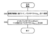
- FIG. 8 is a flowchart showing details of the crossover (S1143).
- the control unit 20 selects two parameter vectors pg_i based on the T image quality evaluation values ag_i calculated in step S112 (S431).
- the parameter vector pg_i is selected by, for example, roulette selection. Specifically, the probability r i of selecting the parameter vector p g_i is calculated by the equation (3) based on the image quality evaluation value a g_i . Based on the probability r i , a parameter vector pg_i is selected.
- the selection of the parameter vector pg_i may be performed by ranking selection. For example, the probability of rank is determined in advance such as probability r 1 for the first place, probability r 2 for the second place, probability r 3 for the third place, and the like. Based on the T image quality evaluation values a g_i , the T parameter vectors pg_i are ranked, and the parameter vector pg_i is selected based on the probability corresponding to the ranking.
- Control unit 20 generates one new parameter vector p g + 1_i based on two parameters vector p g_i (S432). For example, by replacing 1/2 of the probability of two parameters each element of the vector p g_i independently to produce a parameter vector p g + 1_i.
- FIG. 9 is a flowchart showing details of the mutation (S1144).
- the control unit 20 selects one parameter vector pg_i based on the T image quality evaluation values ag_i calculated in step S112 (S441).
- the parameter vector pg_i is selected by, for example, roulette selection or ranking selection described above.
- Control unit 20 generates one new parameter vector p g + 1_i adding changes to each element of the parameter vector p g_i selected (S442). For example, each element of the parameter vector pg_i is randomly changed. Specifically, for example, by replacing the value which is prepared random or pre-probability of 0.1% independently of each element of the parameter vector p g_i, it generates a parameter vector p g + 1_i.
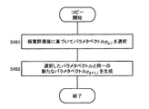
- FIG. 10 is a flowchart showing details of the copy (S1145).
- the control unit 20 selects one parameter vector pg_i based on the T image quality evaluation values ag_i calculated in step S112 (S451).
- the parameter vector pg_i is selected by, for example, roulette selection or ranking selection described above.
- Control unit 20 generates a new parameter vector p g + 1_i the same parameter vector p g_i selected (S452).
- the T parameter vectors p 1 , p 2 , p 3 ,..., P T generated in step S11 are parameter vectors having high image quality evaluation values. Therefore, a parameter vector having a higher image quality evaluation value can be selected by selecting one parameter vector in steps S12 to S15.
- the L2 norm of the feature vector is used as an example of determining a parameter suitable for face recognition using deep learning in the calculation of the image quality evaluation value (S204).
- the image quality evaluation value calculation method is not limited to the above embodiment.
- the image quality evaluation value may be calculated by a function having a feature vector as an input value.
- the image quality evaluation value calculation method may be changed according to the face recognition method.
- Some face recognition methods use a Gabor filter (see “Statistical methods for face detection / face recognition”, Takio Kurita, National Institute of Advanced Industrial Science and Technology (AIST)). In this case, the image quality evaluation value may be calculated based on the Gabor feature amount.
- the Gabor feature value is a feature value based on a specific frequency component in a specific direction, which can be calculated using a Gabor filter.
- This Gabor feature is known to be affected by noise (eg, 22nd Fuzzy System Symposium, Sapporo, September 6-8, 2006, “Cracks on concrete structures using Gabor filters. See “Research on Extraction”).
- the Gabor feature is influenced by blurring (see “21st Image Sensing Symposium, Yokohama, June 2015,“ Study on blur region detection using Gabor filter ”). Therefore, it is considered that there is a correlation between the image quality evaluation value based on the Gabor feature amount of the face image and the face recognition performance.
- the feature vector v i, j (v i, j, 1 , v) of the j-th (1, 2,..., N) face image. i, j, 2 , v i, j, 3 ,..., v i, j, D ), the sum of the elements corresponding to a specific frequency is determined as the image quality evaluation value a i, j of the j th face image . j .
- one camera control device 3 is connected to one camera 2, but a plurality of cameras 2 may be connected to one camera control device 3.
- the number of camera control devices 3 connected to the imaging control device 1 may be one or more.
- parameter determination is performed by the imaging control device 1 such as a server
- parameter setting to the camera 2 is performed by the camera control device 3 such as a personal computer.
- the imaging control device 1 and the camera control device are described.
- the three functions may be performed by one device.
- the imaging control device 1 generates T parameter vectors p i (S1 and S11), but a person may generate T parameter vectors p i .
- the camera control device 3 sets the camera 2 based on the parameter vector p i received from the imaging control device 1. However, a person may set some or all of the parameters of the camera 2.
- the parameter group to be determined may not be suitable for face recognition.
- the image extracted in step S203 is not limited to a face image.
- the feature vector is not limited to the one indicating the feature amount of the face image.
- the image to be extracted and the feature amount may be changed according to the object to be automatically recognized. For example, when determining a parameter group suitable for automatic recognition of a car, the image to be extracted is a car image, and a neural network that has learned the car image is used to generate a feature vector indicating the car feature amount. May be.
- An imaging control apparatus determines a parameter group related to a shooting operation of a camera, and includes an input unit that inputs imaging data generated by the camera and a parameter group based on the imaging data.
- a control unit that selects a parameter group set in the camera from a plurality of candidates, and the control unit acquires imaging data generated by the camera set in the parameter group of each candidate via the input unit,
- a plurality of extraction target images each including an extraction target are extracted from the imaging data for each candidate, an image quality evaluation value is calculated based on the plurality of extraction target images for each candidate, and a plurality of parameter groups are calculated based on the image quality evaluation value. Select one parameter group from the candidates.
- the parameter group based on the imaging data of the camera 2, it is possible to select a parameter value according to the installation position of the camera 2 and the illumination conditions of the surrounding environment. Further, since it is not necessary for a person to adjust the parameter value, the work cost can be reduced.
- control unit may select a parameter group of image quality evaluation values that is the maximum among image quality evaluation values for each candidate.
- the extraction target may be a human face
- the image quality evaluation value may correspond to the degree of suitability for face recognition
- control unit may generate a plurality of parameter group candidates using a genetic algorithm.
- control unit may calculate the image quality evaluation value by calculating the L2 norm of the feature amount of the plurality of extraction target images.
- control unit may calculate the image quality evaluation value by calculating the Gabor feature amount of the plurality of extraction target images.
- the parameter group may include at least two of an aperture value, a gain, a white balance, a shutter speed, and a focal length.
- the imaging control method is an imaging control method in which a calculation unit determines a parameter group related to a shooting operation of a camera, and imaging data generated by a camera set in each of a plurality of parameter group candidates Is extracted via the input unit, a plurality of extraction target images each including the extraction target are extracted from the imaging data for each candidate, and an image quality evaluation value is calculated based on the plurality of extraction target images for each candidate. Based on the above, a parameter group to be set in the camera is selected from among a plurality of parameter group candidates.
- the imaging control device and the imaging control method described in all claims of the present disclosure are realized by cooperation with hardware resources, for example, a processor, a memory, and a program.
- the imaging control device of the present disclosure is useful for setting the parameters of a surveillance camera, for example.
Landscapes
- Engineering & Computer Science (AREA)
- Multimedia (AREA)
- Physics & Mathematics (AREA)
- General Physics & Mathematics (AREA)
- Theoretical Computer Science (AREA)
- General Health & Medical Sciences (AREA)
- Health & Medical Sciences (AREA)
- Quality & Reliability (AREA)
- Signal Processing (AREA)
- Evolutionary Computation (AREA)
- Human Computer Interaction (AREA)
- Computer Vision & Pattern Recognition (AREA)
- Oral & Maxillofacial Surgery (AREA)
- Software Systems (AREA)
- Computing Systems (AREA)
- Vascular Medicine (AREA)
- Medical Informatics (AREA)
- Databases & Information Systems (AREA)
- Artificial Intelligence (AREA)
- Studio Devices (AREA)
- Exposure Control For Cameras (AREA)
- Image Analysis (AREA)
Abstract
カメラの設置状況に応じたパラメタを決定する撮像制御装置、撮像制御方法、及びプログラムを提供する。撮像制御装置(1)は、カメラ(2)の撮影動作に関するパラメタ群を決定する撮像制御装置であって、カメラが生成した撮像データを入力する入力部(10)と、撮像データに基づいて、パラメタ群の複数の候補の中からカメラに設定するパラメタ群を選択する制御部(20)と、を備え、制御部(20)は、各候補のパラメタ群に設定されたカメラが生成した撮像データを入力部を介して取得し、候補毎に撮像データから抽出対象をそれぞれ含む複数の抽出対象画像を抽出し、候補毎に複数の抽出対象画像に基づいて画質評価値を算出し、画質評価値に基づいて、パラメタ群の複数の候補の中からいずれか一つのパラメタ群を選択する。
Description
本開示は、カメラの撮影動作に関するパラメタを決定する撮像制御装置、撮像制御方法、及びプログラムに関する。
特許文献1は、コントラスト方式で合焦する撮像装置を開示している。この撮像装置は、同一人物の被写体画像領域と部分画像領域とを組みで検索する場合と、被写体画像領域と部分画像領域との組みが検出された後に検出された領域について検索対象の画像を含むか否かを再度判定する場合とで、それぞれの検索に適した異なる検索条件を用いる。被写体画像領域と部分画像領域とを組みで検索することによって人物の検出漏れを抑制しながら、組みで検索するときに誤検出された領域を再判定により除外して、人物や顔の検出率を向上させている。検出率の向上が焦点探索領域の安定化に繋がる。これにより、コントラスト方式で合焦する場合におけるフォーカス制御の安定性を向上させている。
特許文献2は、監視対象を撮像する撮像装置を開示している。この撮像装置は、絞り値と少なくともシャッター速度およびゲイン値のいずれか一方を含む動作パラメタの値を変更することによって、撮像素子の出力信号の輝度レベルを目標値に近づける自動露出制御手段を有する。自動露出制御手段は、絞り値を小絞り端寄りの所定値にした状態で監視対象の明るさが暗くなった場合に、通常監視モードよりも異常監視モードが設定されているときのほうが、絞り値を優先して変更する。これにより、異常状態を高画質で撮影すると共に耐久性を向上させている。
本開示は、カメラの設置状況に応じたパラメタを決定する撮像制御装置、撮像制御方法、及びプログラムを提供する。
本開示の撮像制御装置は、カメラの撮影動作に関するパラメタ群を決定する撮像制御装置であって、カメラが生成した撮像データを入力する入力部と、撮像データに基づいて、パラメタ群の複数の候補の中からカメラに設定するパラメタ群を選択する制御部と、を備え、制御部は、各候補のパラメタ群に設定されたカメラが生成した撮像データを入力部を介して取得し、候補毎に撮像データから抽出対象をそれぞれ含む複数の抽出対象画像を抽出し、候補毎に複数の抽出対象画像に基づいて画質評価値を算出し、画質評価値に基づいて、パラメタ群の複数の候補の中からいずれか一つのパラメタ群を選択する。
これらの概括的かつ特定の態様は、システム、方法、及びコンピュータプログラム、並びに、それらの組み合わせにより、実現されてもよい。
本開示の撮像制御装置、撮像制御方法、及びプログラムによれば、カメラの撮像データに基づいて算出した画質評価値に基づいて、カメラに設定するパラメタ群を決定している。よって、カメラの設置状況に応じたパラメタを決定することができる。
(本開示の基礎となった知見)
監視カメラなどのカメラを新たに設置するとき又はレイアウト変更によって設置位置を変更するときは、カメラの撮影動作に関するパラメタ群をカメラの設置状況に応じた適当な値に設定する必要がある。例えば、カメラの設置状況として、カメラの設置位置及び周辺環境の照明条件等がある。
監視カメラなどのカメラを新たに設置するとき又はレイアウト変更によって設置位置を変更するときは、カメラの撮影動作に関するパラメタ群をカメラの設置状況に応じた適当な値に設定する必要がある。例えば、カメラの設置状況として、カメラの設置位置及び周辺環境の照明条件等がある。
カメラの撮影動作に関するパラメタ群には、露光時間、フォーカス、圧縮品質等を設定するための複数種類のパラメタが含まれる。しかし、複数種類のパラメタの最適値を、カメラの設置位置及び周辺環境の照明条件等を考慮して、人間が決定することは難しい。例えば、画像のノイズを減らすために、露光時間を長くすると、動きによるボケが生じやすくなる。また、画像のノイズを減らすために、絞りを大きく開口すると、被写界深度が浅くなり、距離によるボケが生じやすくなる。また、カメラの明るさとボケやすさの間にもトレードオフの関係がある。よって、どのパラメタをどの値にすべきかを人間が決定することは難しかった。
さらに、空港及びショッピングセンタのような施設又は街中に、数百台の監視カメラが設置されることがある。このような多数の監視カメラに対して、1台ずつカメラのパラメタ群を、カメラの設置位置及び周辺環境の照明条件等に応じて手動で決定すると、時間がかかる。また、一度設置したカメラをレイアウト変更に伴って位置を変更したときに、カメラの台数が多いとパラメタ群を手動で再設定することが容易ではない。
本開示は、(I)カメラの撮影動作に関する複数種類のパラメタを、カメラの設置位置及び周辺環境の照明条件等に応じた適当な値に決定する撮像制御装置を提供する。
複数の監視カメラを使用して、特定の人物を探索することがある。このような監視カメラ等において、近年、深層学習等の機械学習を利用した自動顔認識が行われている。この自動顔認識に最適なパラメタ値を人間の主観による評価に基づいて決定することは難しい。例えば、人間は高周波領域の特徴が残っていると画質が良いと判断する。しかし、自動顔認識においては、一定以上の周波数領域はノイズに対してセンシティブなため利用されない。さらに、パラメタの良し悪しは、利用する自動顔認識のアルゴリズムにも依存する。しかし、人間には、例えば、ボケているが明るい画像と、シャープだが暗い画像のどちらが、自動顔認識に適しているかを判断することは困難である。
特許文献1は、撮像画像において合焦したい領域のコントラストに基づいてフォーカス制御を行っている。しかし、シャッタースピードを速くすることによってコントラストを向上させると、輝度レベルが低下する。一方、シャッタースピードを遅くして輝度レベルを向上させると、動きぼけによるコントラストの低下が生じる。よって、コントラストだけを指標とした場合、輝度レベルが考慮されず、顔認識に悪影響を及ぼす可能性がある。そのため、コントラストが顔認識に適した指標とは限らない。
特許文献2は、撮像画像の明るさ調整を、輝度レベルを目標値に近づけるという方法で実現している。しかし、輝度レベルが顔認識にとって適切な指標であるとは限らない。また、目標値をどのように設定するかが明確に定められていない。すなわち、顔認識に適した目標値が設定されていない。
よって、従来は、カメラの撮影動作に関する複数種類のパラメタを顔認識に適した値に決定することが難しかった。
本開示は、(II)顔認識に適したパラメタ群を決定する撮像制御装置を提供する。
下記実施形態では、(I)カメラの設置位置及び周辺環境の照明条件等に応じた適当な値であって、且つ、(II)顔認識に適した値のパラメタを決定する撮像制御装置について説明する。具体的には、本開示の撮像制御装置は、監視カメラなどのカメラが撮影した動画から顔画像の特徴量に基づく画質評価値を算出し、画質評価値に基づいてカメラに設定するパラメタ群を決定する。これにより、カメラの設置位置及び周辺環境の照明条件等に応じた、顔認識に適したパラメタ群をカメラに設定することができる。よって、顔認識の性能が向上する。
(第1実施形態)
以下、第1実施形態について、図面を参照しながら説明する。本実施形態では、深層学習を用いて顔認識するのに適したカメラのパラメタ群の設定について説明する。
以下、第1実施形態について、図面を参照しながら説明する。本実施形態では、深層学習を用いて顔認識するのに適したカメラのパラメタ群の設定について説明する。
1. 構成
図1は、本開示の撮像制御装置の電気的構成を示している。例えば、撮像制御装置1はサーバであり、カメラ2は監視カメラであり、カメラ制御装置3はパソコンである。撮像制御装置1は、例えば、クラウドサーバであり、インターネット経由により、1つ以上のカメラ制御装置3と接続される。図1の例では、1つのカメラ制御装置3に対して1台のカメラ2が接続される。撮像制御装置1は、例えば、複数のカメラ2が空港などに新たに設置されるときに、複数のカメラ2のそれぞれのパラメタ群を決定する。
図1は、本開示の撮像制御装置の電気的構成を示している。例えば、撮像制御装置1はサーバであり、カメラ2は監視カメラであり、カメラ制御装置3はパソコンである。撮像制御装置1は、例えば、クラウドサーバであり、インターネット経由により、1つ以上のカメラ制御装置3と接続される。図1の例では、1つのカメラ制御装置3に対して1台のカメラ2が接続される。撮像制御装置1は、例えば、複数のカメラ2が空港などに新たに設置されるときに、複数のカメラ2のそれぞれのパラメタ群を決定する。
撮像制御装置1は、通信部10、制御部20、記憶部30、及びバス40を備える。
通信部10は、所定の通信規格に準拠して外部機器との通信を行う回路を含む。所定の通信規格は、例えば、LAN、Wi-Fi(登録商標)、Bluetooth(登録商標)、USB、HDMI(登録商標)を含む。
制御部20は、撮像制御装置1の動作を制御する。制御部20は、半導体素子などで実現可能である。制御部20は、例えば、マイコン、CPU、MPU、DSP、FPGA、ASICで構成することができる。制御部20の機能は、ハードウェアのみで構成してもよいし、ハードウェアとソフトウェアとを組み合わせることにより実現してもよい。制御部20は、記憶部30に格納されたデータやプログラムを読み出して種々の演算処理を行い、所定の機能を実現する。制御部20によって実行されるプログラムは、通信部10等から提供されてもよいし、可搬性を有する記録媒体に格納されていてもよい。
制御部20は、カメラ2が生成した撮像データに基づいて、カメラ2の撮影動作に関するパラメタ群を決定する。カメラ2のパラメタ群は、画質に影響する複数種類のパラメタを含む。例えば、パラメタ群は、絞り値、ゲイン、ホワイトバランス、シャッタースピード、及び焦点距離のうちの1つ以上を含む。
記憶部30は、例えば、ハードディスク(HDD)、SSD、RAM、DRAM、強誘電体メモリ、フラッシュメモリ、磁気ディスク、又はこれらの組み合わせによって実現できる。
バス40は、通信部10、制御部20、及び記憶部30を電気的に接続する信号線である。
撮像制御装置1は、さらに、ユーザによる種々の操作を入力するユーザインタフェースを含んでもよい。例えば、撮像制御装置1は、キーボード、ボタン、スイッチ、及びこれらの組み合わせを含んでもよい。
カメラ2は、CCDイメージセンサ、CMOSイメージセンサ、又はNMOSイメージセンサなどの撮像素子を含む。
カメラ制御装置3は、撮像制御装置1が決定したパラメタ群に基づいてカメラ2を設定する。
2. 動作
2.1 パラメタベクトルの決定
図2は、撮像制御装置1の制御部20によるパラメタベクトルの決定の動作を示すフローチャートである。
2.1 パラメタベクトルの決定
図2は、撮像制御装置1の制御部20によるパラメタベクトルの決定の動作を示すフローチャートである。
制御部20は、T個のパラメタベクトルpi(i=1,2,・・・,T)、すなわち、パラメタベクトルp1,p2,p3,・・・,pTを生成する(S1)。パラメタベクトルpiは、複数のパラメタを含むパラメタ群である。例えば、各パラメタベクトルpiには、M個の要素であるパラメタpi,1,pi,2,pi,3・・・pi,Mが含まれる。各パラメタpi,1,pi,2,pi,3・・・pi,Mは、絞り値、ゲイン、ホワイトバランス、シャッタースピード、及び焦点距離などに対応する。T個のパラメタベクトルpiは、Tパターンのパラメタベクトルpiを構成する。すなわち、パラメタベクトルpiに含まれる要素のうちの1つ以上が、他のパラメタベクトルpiに含まれる同一種類の要素と異なる値を持つ。例えば、絞り値、ゲイン、ホワイトバランス、シャッタースピード、及び焦点距離のうちの少なくともいずれか一つが異なる。T個のパラメタベクトルpiの生成方法は任意である。例えば、設定可能な値の全ての組み合わせによって、T個のパラメタベクトルpiを生成してもよい。ステップS1で生成されるT個のパラメタベクトルpiは、最終的にカメラ2に設定されるパラメタ群の候補となる。
制御部20は、パラメタベクトルpiについて画質評価値aiを算出する(S2)。本実施形態における画質評価値aiは画像認識に関連し、具体的には顔認識に対する適合度に対応する。
制御部20は、算出した画質評価値aiが既に算出した画質評価値の中で最大か否かを判断する(S3)。画質評価値aiが最大であれば、そのパラメタベクトルpiを最適なパラメタベクトルpoptに決定する(S4)。画質評価値aiが最大でなければ、ステップS4をスキップする。
制御部20は、T個のパラメタベクトルpiの全てについて、画質評価値aiに基づく評価が完了したか否かを判断する(S5)。評価していないパラメタベクトルpiがあれば、ステップS2に戻る。
T個のパラメタベクトルpiについての評価が完了すれば、パラメタベクトルpoptを最適なカメラパラメタとしてカメラ制御装置3に出力する(S6)。
2.2 画質評価値の算出
図3は、画質評価値の算出(S2)の詳細を示している。制御部20は、パラメタベクトルpiをカメラ制御装置3に出力することによって、カメラ2の各種パラメタを設定する(S201)。
図3は、画質評価値の算出(S2)の詳細を示している。制御部20は、パラメタベクトルpiをカメラ制御装置3に出力することによって、カメラ2の各種パラメタを設定する(S201)。
制御部20は、パラメタベクトルpiで示される値に設定されたカメラ2が撮影して生成した撮像データを取得する(S202)。撮像データは、例えば、1枚以上の画像を含む動画である。制御部20は、撮像データからN個の顔画像を抽出する(S203)。顔画像の抽出方法は任意である。
制御部20は、N個の顔画像を用いて画質評価値aiを算出する(S204)。例えば、N個の顔画像の特徴量に基づいて画質評価値aiを算出する。制御部20は、パラメタベクトルpiと画質評価値aiを対応付けて記憶部30に記録する。
図4を参照して、画質評価値aiの算出(S204)の具体例について説明する。図4は、顔画像の特徴量の一例である特徴ベクトルvi,jの算出例を示している。本実施形態では、顔画像を学習したニューラルネットワークを使用して、特徴ベクトルvi,j(j=1,2,・・・,N)を生成する。ニューラルネットワークは、例えば、多数の顔画像を示す学習データと、その顔画像が誰であるかを示すラベルとを対応付けて、事前に学習したものである。学習済みのニューラルネットワークは、記憶部30に格納されている。ニューラルネットワークは、深層学習に用いられる多層構造を持つ。例えば、ニューラルネットワークは、入力層L1、中間層L2,L3,L4、及び出力層L5を含む。中間層の数は3層に限らない。中間層は、1つ以上の層を含む。ニューラルネットワークは、例えば、入力層L1に入力された顔画像が誰かを示すベクトルを出力層L5から出力する。
制御部20は、ステップS203で抽出した1番目からN番目までの顔画像を順にニューラルネットワークの入力層L1に入力する。本実施形態では、例えば、j番目(j=1,2,・・・,N)の顔画像について、出力層L5に最も近い中間層L4のノード値vi,j,1,vi,j,2,vi,j,3,・・・,vi,j,Dから、特徴ベクトルvi,j=(vi,j,1,vi,j,2,vi,j,3,・・・,vi,j,D)を生成する。
制御部20は、N個の顔画像のそれぞれの特徴ベクトルvi,j(j=1,2,・・・,N)から、各顔画像に対する画質評価値ai,jを算出する。具体的には、制御部20は、N個のそれぞれの画質評価値ai,jとして、特徴ベクトルvi,jのL2ノルムの値li,jを式(1)により算出する。L2ノルムと画像の品質には関係性がある(例えば、著者Rajeev Ranjan, Carlos D. Castillo,Rama Chellappaの「L2-constrained Softmax Loss for Discriminative Face Verification」を参照)。よって、本実施形態では、L2ノルムの値li,jを各顔画像の画質評価値ai,jとして利用する。

制御部20は、式(2)に示すようにN個の顔画像の画質評価値ai,jの平均値をパラメタベクトルpiの画質評価値aiとして算出する。

3. 効果及び補足
撮像制御装置1は、カメラ2の撮影動作に関するパラメタ群を決定する。撮像制御装置1は、カメラ2が生成した撮像データを入力する通信部10と、撮像データに基づいて、パラメタ群の複数の候補の中からカメラに設定するパラメタ群を選択する制御部20と、を備える。制御部20は、各候補のパラメタ群に設定されたカメラが生成した撮像データを入力部を介して取得し、候補毎に撮像データから複数の顔画像を抽出し、候補毎に複数の顔画像に基づいて画質評価値を算出し、画質評価値に基づいて、パラメタ群の複数の候補の中からいずれか一つのパラメタ群を選択する。
撮像制御装置1は、カメラ2の撮影動作に関するパラメタ群を決定する。撮像制御装置1は、カメラ2が生成した撮像データを入力する通信部10と、撮像データに基づいて、パラメタ群の複数の候補の中からカメラに設定するパラメタ群を選択する制御部20と、を備える。制御部20は、各候補のパラメタ群に設定されたカメラが生成した撮像データを入力部を介して取得し、候補毎に撮像データから複数の顔画像を抽出し、候補毎に複数の顔画像に基づいて画質評価値を算出し、画質評価値に基づいて、パラメタ群の複数の候補の中からいずれか一つのパラメタ群を選択する。
このように、カメラ2の撮像データに基づいてパラメタ群を決定することによって、カメラ2の設置位置及び周辺環境の照明条件に応じたパラメタ値を選択することができる。よって、例えば、空港及びショッピングセンタのような施設などに、数百台の監視カメラを設置するようなときに、各カメラのパラメタ値をカメラ2の設置位置及び周辺環境の照明条件に応じて人が決定する必要がなくなるため、パラメタ調整による作業コストを軽減することができる。
さらに、本実施形態によれば、カメラ2の撮像データから算出した顔認識に対する適合度を示す画質評価値に基づいて、カメラ2に設定するパラメタ群を決定している。よって、顔認識の性能が向上する。
制御部20は、候補毎の画質評価値の中で最大となる画質評価値のパラメタ群を選択する。これにより、カメラ2の設置位置及び周辺環境の照明条件に応じて最適なパラメタ群が選択されうる。また、顔認識に最適なパラメタ群が選択されうる。例えば、顔が誤検出された場合、画質評価値は低くなる。よって、顔が誤検出されるようなパラメタ群が選択されることを防ぐことができる。
制御部20は、複数の顔画像の特徴量のL2ノルムを算出することによって、画質評価値を算出する。顔画像の特徴量のL2ノルムと、画像の品質には関係性がある。よって、顔画像の特徴量のL2ノルムにより算出した画質評価値に基づいてパラメタ群を選択することによって、カメラ2の設置位置及び周辺環境の照明条件に応じた且つ顔認識に適したパラメタ群を選択することができる。
(第2実施形態)
第1実施形態では、T個のパラメタベクトルの生成(S1)の方法は任意であった。本実施形態では、遺伝的アルゴリズム(GA)を使用して、T個のパラメタベクトルを生成する。
第1実施形態では、T個のパラメタベクトルの生成(S1)の方法は任意であった。本実施形態では、遺伝的アルゴリズム(GA)を使用して、T個のパラメタベクトルを生成する。
図5は、第2実施形態における、撮像制御装置1の制御部20によるパラメタベクトルの決定の動作を示すフローチャートである。制御部20は、遺伝的アルゴリズムによって、T個のパラメタベクトルpi(i=1,2,3,・・・,T)を生成する(S11)。図5において、パラメタベクトルpiを遺伝的アルゴリズムによって生成すること以外は、第1実施形態の図2と同一である。すなわち、図5のステップS12~S16は、図2のステップS2~S6と同一である。
図6は、遺伝的アルゴリズムを使用したT個のパラメタベクトルpi(i=1,2,3,・・・,T)の生成(S11)の詳細を示している。制御部20は、現世代の一世代目である初期世代のT個のパラメタベクトルp1_i(i=1,2,3,・・・,T)、すなわち、パラメタベクトルp1_1,p1_2,p1_3,・・・,p1_Tを生成する(S111)。
制御部20は、現世代のT個のパラメタベクトルpg_iについて画質評価値ag_iを算出する(S112)。ステップS111の直後は、初期世代のT個のパラメタベクトルp1_i(g=1)について画質評価値a1_iを算出する(S112)。ステップS112における画質評価値の算出は、図2のステップS2と同一の方法で行う。すなわち、ステップS112は、第1実施形態の図3に示すステップS201~S204に対応する。
制御部20は、現世代のT個のパラメタベクトルpg_iについて、画質評価値ag_iの算出が完了したか否かを判断する(S113)。現世代のT個のパラメタベクトルpg_iについての画質評価値ag_iの算出が完了していなければ、ステップS112に戻る。
現世代のT個のパラメタベクトルpg_iについての画質評価値ag_iの算出が完了すれば、制御部20は、現世代のT個の画質評価値ag_iに基づいて、次世代のT個のパラメタベクトルpg+1_i(i=1,2,・・・,T)を生成する(S114)。制御部20は、次世代のT個のパラメタベクトルpg+1_iの生成が完了したか否かを判断する(S115)。次世代のパラメタベクトルpg+1_iがT個に達するまで、ステップS114を繰り返す。
次世代のT個のパラメタベクトルpg+1_iの生成が完了すれば、次世代のT個のパラメタベクトルpg+1_iの各要素の値を現世代のT個のパラメタベクトルpg_iに移す(S116)。
制御部20は、現世代が最終世代に達したか否かを判断する(S117)。最終世代に達するまで、ステップS112~S117を繰り返す。
制御部20は、現世代が最終世代に達すると、ステップS116によって得られる最終世代のT個のパラメタベクトルpg_iを記憶部30に格納する(S118)。これにより、最終的に現世代の中で最も画質評価値の高いT個のパラメタベクトルが、遺伝的アルゴリズムの解として得られることになる。
図7は、次世代のT個のパラメタベクトルpg+1_iの生成(S114)の詳細を示している。制御部20は、ある確率でパラメタベクトルpg+1_iの生成方法を交叉、突然変異、及びコピーの中から決定する(S1141)。
決定した生成方法が交叉、突然変異、及びコピーのいずれであるかを判断し(S1142)、制御部20は、判断結果の交叉(S1143)、突然変異(S1144)、及びコピー(S1145)のいずれかによって、1つのパラメタベクトルpg+1_iを生成する。
図8は、交叉(S1143)の詳細を示すフローチャートである。制御部20は、ステップS112で算出したT個の画質評価値ag_iに基づいて、パラメタベクトルpg_iを2つ選択する(S431)。
パラメタベクトルpg_iの選択は、例えば、ルーレット選択によって行う。具体的には、画質評価値ag_iに基づいて、パラメタベクトルpg_iを選ぶ確率riを式(3)により算出する。確率riに基づいて、パラメタベクトルpg_iを選択する。

パラメタベクトルpg_iの選択は、ランキング選択によって行ってもよい。例えば、ランクの確率を、一位なら確率r1、二位なら確率r2、三位なら確率r3などのように予め決めておく。T個の画質評価値ag_iに基づいて、T個のパラメタベクトルpg_iをランク付けし、ランク付けに対応する確率に基づいて、パラメタベクトルpg_iを選択する。
制御部20は、2つのパラメタベクトルpg_iをもとに1つの新たなパラメタベクトルpg+1_iを生成する(S432)。例えば、2つのパラメタベクトルpg_iの各要素を独立に1/2の確率で入れ替えて、パラメタベクトルpg+1_iを生成する。
図9は、突然変異(S1144)の詳細を示すフローチャートである。制御部20は、ステップS112で算出したT個の画質評価値ag_iに基づいて、パラメタベクトルpg_iを1つ選択する(S441)。パラメタベクトルpg_iの選択は、例えば、上述したルーレット選択又はランキング選択によって行う。制御部20は、選択したパラメタベクトルpg_iの各要素に変化を加えて1つの新たなパラメタベクトルpg+1_iを生成する(S442)。例えば、パラメタベクトルpg_iの各要素をランダムに変更する。具体的には、例えば、パラメタベクトルpg_iの各要素を独立に0.1%の確率で乱数又は事前に用意した値に入れ替えることによって、パラメタベクトルpg+1_iを生成する。
図10は、コピー(S1145)の詳細を示すフローチャートである。制御部20は、ステップS112で算出したT個の画質評価値ag_iに基づいて、パラメタベクトルpg_iを1つ選択する(S451)。パラメタベクトルpg_iの選択は、例えば、上述したルーレット選択又はランキング選択によって行う。制御部20は、選択したパラメタベクトルpg_iと同一の新たなパラメタベクトルpg+1_iを生成する(S452)。
これにより、ステップS11において生成されるT個のパラメタベクトルp1,p2,p3,・・・,pTは、画質評価値が高いパラメタベクトルとなる。よって、この中からステップS12~S15において、パラメタベクトルを1つ選択することによって、画質評価値がより高いパラメタベクトルを選択することができる。
(他の実施形態)
以上のように、本出願において開示する技術の例示として、上記第1及び第2実施形態を説明した。しかしながら、本開示における技術は、これに限定されず、適宜、変更、置き換え、付加、省略などを行った実施形態にも適用可能である。そこで、以下、他の実施形態を例示する。
以上のように、本出願において開示する技術の例示として、上記第1及び第2実施形態を説明した。しかしながら、本開示における技術は、これに限定されず、適宜、変更、置き換え、付加、省略などを行った実施形態にも適用可能である。そこで、以下、他の実施形態を例示する。
上記実施形態は、画質評価値の算出(S204)において、深層学習を利用した顔認識に適したパラメタを決定する例として、特徴ベクトルのL2ノルムを使用した。しかし、画質評価値の算出方法は、上記実施形態に限らない。例えば、画質評価値は、特徴ベクトルを入力値とする関数によって、算出されてもよい。例えば、画質評価値の算出方法は、顔認識の手法に応じて変えてもよい。顔認識の手法として、Gaborフィルタを使用するものがある(「顔検出・顔認識のための統計的手法」、栗田多喜夫、産業技術総合研究所脳神経情報研究部門を参照)。この場合、Gabor特徴量に基づいて画質評価値を算出してもよい。Gabor特徴量は、Gaborフィルタを用いて算出することができる、特定の方向の特定の周波数成分に基づく特徴量である。このGabor特徴量は、ノイズの影響を受けることが知られている(例えば、第22回ファジィシステムシンポジウム、札幌、2006年9月6~8日、「ガボールフィルタを用いたコンクリート構造物上のひび割れ抽出に関する研究」を参照)。また、Gabor特徴量は、ボケの影響を受けることが知られている(第21回画像センシングシンポジウム、横浜、2015年6月、「ガボールフィルタを用いたぼけ領域検出に関する研究」を参照)。よって、顔画像のGabor特徴量に基づく画質評価値と顔認識性能には相関があると考えられる。Gabor特徴量に基づく画質評価値を算出する場合、ステップS204において、j番目(1,2,・・・,N)の顔画像の特徴ベクトルvi,j=(vi,j,1,vi,j,2,vi,j,3,・・・,vi,j,D)のうち、特定の周波数に該当する要素の総和を、j番目の顔画像の画質評価値ai,jとする。N個の顔画像の画質評価値ai,jに基づいて、式(2)により、パラメタベクトルpiの画質評価値aiを算出する。
上記実施形態では、1台のカメラ2に対して1つのカメラ制御装置3が接続されたが、1つのカメラ制御装置3に複数のカメラ2が接続されてもよい。撮像制御装置1に接続されるカメラ制御装置3の数は1つ以上であってもよい。
上記実施形態では、パラメタの決定はサーバなどの撮像制御装置1が行い、カメラ2へのパラメタの設定はパソコンなどのカメラ制御装置3が行う例について説明したが、撮像制御装置1とカメラ制御装置3の機能は一つの装置によって実行されてもよい。
上記実施形態では、撮像制御装置1がT個のパラメタベクトルpiを生成したが(S1及びS11)、人がT個のパラメタベクトルpiを生成してもよい。
上記実施形態では、カメラ制御装置3が、撮像制御装置1から受信したパラメタベクトルpiにより、カメラ2を設定した。しかし、カメラ2の一部又は全部のパラメタの設定を、人が行ってもよい。
上記実施形態では、顔認識に適したパラメタ群を決定する例について説明したが、決定するパラメタ群は顔認識に適したものでなくてもよい。カメラ2の設置位置又は撮像データの使用用途等に応じたパラメタ群を決定してもよい。この場合、ステップS203で抽出する画像は顔画像に限定しない。また、特徴ベクトルは顔画像の特徴量を示すものに限定しない。自動認識しようとする対象に応じて、抽出する画像及び特徴量を変えてもよい。例えば、車の自動認識に適したパラメタ群を決定する場合、抽出する画像は車の画像であって、車の画像を学習したニューラルネットワークを使用して、車の特徴量を示す特徴ベクトルを生成してもよい。
(実施形態の概要)
(1)本開示の撮像制御装置は、カメラの撮影動作に関するパラメタ群を決定する撮像制御装置であって、カメラが生成した撮像データを入力する入力部と、撮像データに基づいて、パラメタ群の複数の候補の中からカメラに設定するパラメタ群を選択する制御部と、を備え、制御部は、各候補のパラメタ群に設定されたカメラが生成した撮像データを入力部を介して取得し、候補毎に撮像データから抽出対象をそれぞれ含む複数の抽出対象画像を抽出し、候補毎に複数の抽出対象画像に基づいて画質評価値を算出し、画質評価値に基づいて、パラメタ群の複数の候補の中からいずれか一つのパラメタ群を選択する。
(1)本開示の撮像制御装置は、カメラの撮影動作に関するパラメタ群を決定する撮像制御装置であって、カメラが生成した撮像データを入力する入力部と、撮像データに基づいて、パラメタ群の複数の候補の中からカメラに設定するパラメタ群を選択する制御部と、を備え、制御部は、各候補のパラメタ群に設定されたカメラが生成した撮像データを入力部を介して取得し、候補毎に撮像データから抽出対象をそれぞれ含む複数の抽出対象画像を抽出し、候補毎に複数の抽出対象画像に基づいて画質評価値を算出し、画質評価値に基づいて、パラメタ群の複数の候補の中からいずれか一つのパラメタ群を選択する。
このように、カメラ2の撮像データに基づいてパラメタ群を決定することによって、カメラ2の設置位置及び周辺環境の照明条件に応じたパラメタ値を選択することができる。また、人がパラメタ値を調整する必要がなくなるため、作業コストを軽減することができる。
(2)(1)の撮像制御装置において、制御部は、候補毎の画質評価値の中で最大となる画質評価値のパラメタ群を選択してもよい。
これにより、カメラ2の設置位置及び周辺環境の照明条件により適したパラメタ群を選択することができる。
(3)(1)又は(2)の撮像制御装置において、抽出対象は人の顔であり、画質評価値は顔認識に対する適合度に対応してもよい。
これにより、顔認識に適したパラメタ群が選択されるため、顔認識の性能が向上する。
(4)(1)から(3)の撮像制御装置において、制御部は、パラメタ群の複数の候補を、遺伝的アルゴリズムを使用して生成してもよい。
これにより、画質評価値が高いパラメタ群の候補の中から、よりよいパラメタ群が選択されうる。
(5)(1)から(4)の撮像制御装置において、制御部は、複数の抽出対象画像の特徴量のL2ノルムを算出することによって、画質評価値を算出してもよい。
(6)(1)から(4)の撮像制御装置において、制御部は、複数の抽出対象画像のGabor特徴量を算出することによって、画質評価値を算出してもよい。
(7)(1)から(6)の撮像制御装置において、パラメタ群は、絞り値、ゲイン、ホワイトバランス、シャッタースピード、及び焦点距離のうちの少なくとも2つを含んでもよい。
(8)本開示の撮像制御方法は、演算部により、カメラの撮影動作に関するパラメタ群を決定する撮像制御方法であって、パラメタ群の複数の候補の各々に設定されたカメラが生成した撮像データを入力部を介して取得し、候補毎に撮像データから抽出対象をそれぞれ含む複数の抽出対象画像を抽出し、候補毎に複数の抽出対象画像に基づいて画質評価値を算出し、画質評価値に基づいて、パラメタ群の複数の候補の中から、カメラに設定するパラメタ群を選択する。
本開示の全請求項に記載の撮像制御装置及び撮像制御方法は、ハードウェア資源、例えば、プロセッサ、メモリ、及びプログラムとの協働などによって、実現される。
本開示の撮像制御装置は、例えば、監視カメラのパラメタの設定に有用である。
1 撮像制御装置
2 カメラ
3 カメラ制御装置
10 通信部
20 制御部
30 記憶部
2 カメラ
3 カメラ制御装置
10 通信部
20 制御部
30 記憶部
Claims (9)
- カメラの撮影動作に関するパラメタ群を決定する撮像制御装置であって、
前記カメラが生成した撮像データを入力する入力部と、
前記撮像データに基づいて、前記パラメタ群の複数の候補の中から前記カメラに設定するパラメタ群を選択する制御部と、
を備え、
前記制御部は、
各候補のパラメタ群に設定されたカメラが生成した撮像データを前記入力部を介して取得し、
候補毎に前記撮像データから抽出対象をそれぞれ含む複数の抽出対象画像を抽出し、
候補毎に前記複数の抽出対象画像に基づいて画質評価値を算出し、
前記画質評価値に基づいて、前記パラメタ群の複数の候補の中からいずれか一つのパラメタ群を選択する、
撮像制御装置。 - 前記制御部は、前記候補毎の画質評価値の中で最大となる画質評価値のパラメタ群を選択する、
請求項1に記載の撮像制御装置。 - 前記抽出対象は人の顔であり、前記画質評価値は顔認識に対する適合度に対応する、請求項1又は請求項2に記載の撮像制御装置。
- 前記制御部は、前記パラメタ群の複数の候補を、遺伝的アルゴリズムを使用して生成する、
請求項1から請求項3のいずれかに記載の撮像制御装置。 - 前記制御部は、前記複数の抽出対象画像の特徴量のL2ノルムを算出することによって、前記画質評価値を算出する、請求項1から請求項4のいずれかに記載の撮像制御装置。
- 前記制御部は、前記複数の抽出対象画像のGabor特徴量を算出することによって、前記画質評価値を算出する、請求項1から請求項4のいずれかに記載の撮像制御装置。
- 前記パラメタ群は、絞り値、ゲイン、ホワイトバランス、シャッタースピード、及び焦点距離のうちの少なくとも2つを含む、請求項1から請求項6のいずれかに記載の撮像制御装置。
- 演算部により、カメラの撮影動作に関するパラメタ群を決定する撮像制御方法であって、
パラメタ群の複数の候補の各々に設定されたカメラが生成した撮像データを入力部を介して取得し、
候補毎に前記撮像データから抽出対象をそれぞれ含む複数の抽出対象画像を抽出し、
候補毎に前記複数の抽出対象画像に基づいて画質評価値を算出し、
前記画質評価値に基づいて、前記パラメタ群の複数の候補の中から、前記カメラに設定するパラメタ群を選択する、
撮像制御方法。 - コンピュータに請求項8に記載の撮像制御方法を実行させるためのプログラム。
Priority Applications (4)
| Application Number | Priority Date | Filing Date | Title |
|---|---|---|---|
| EP19818508.4A EP3806447A4 (en) | 2018-06-11 | 2019-05-07 | IMAGING CONTROL DEVICE, IMAGING CONTROL METHOD, AND PROGRAM |
| CN201980038771.0A CN112272945A (zh) | 2018-06-11 | 2019-05-07 | 摄像控制装置、摄像控制方法以及程序 |
| JP2020525330A JP7246029B2 (ja) | 2018-06-11 | 2019-05-07 | 撮像制御装置、撮像制御方法、及びプログラム |
| US17/108,294 US20210112191A1 (en) | 2018-06-11 | 2020-12-01 | Imaging control device, imaging control method, and non-transitory computer-readable recording medium |
Applications Claiming Priority (2)
| Application Number | Priority Date | Filing Date | Title |
|---|---|---|---|
| JP2018-111389 | 2018-06-11 | ||
| JP2018111389 | 2018-06-11 |
Related Child Applications (1)
| Application Number | Title | Priority Date | Filing Date |
|---|---|---|---|
| US17/108,294 Continuation US20210112191A1 (en) | 2018-06-11 | 2020-12-01 | Imaging control device, imaging control method, and non-transitory computer-readable recording medium |
Publications (1)
| Publication Number | Publication Date |
|---|---|
| WO2019239744A1 true WO2019239744A1 (ja) | 2019-12-19 |
Family
ID=68843180
Family Applications (1)
| Application Number | Title | Priority Date | Filing Date |
|---|---|---|---|
| PCT/JP2019/018270 WO2019239744A1 (ja) | 2018-06-11 | 2019-05-07 | 撮像制御装置、撮像制御方法、及びプログラム |
Country Status (5)
| Country | Link |
|---|---|
| US (1) | US20210112191A1 (ja) |
| EP (1) | EP3806447A4 (ja) |
| JP (1) | JP7246029B2 (ja) |
| CN (1) | CN112272945A (ja) |
| WO (1) | WO2019239744A1 (ja) |
Citations (8)
| Publication number | Priority date | Publication date | Assignee | Title |
|---|---|---|---|---|
| JPS4921204B1 (ja) | 1970-12-22 | 1974-05-30 | ||
| JPS5829679B2 (ja) | 1977-03-01 | 1983-06-24 | 日本電気株式会社 | 時分割通話路制御方式 |
| JP2008191816A (ja) * | 2007-02-02 | 2008-08-21 | Sony Corp | 画像処理装置、および画像処理方法、並びにコンピュータ・プログラム |
| US20140148690A1 (en) * | 2012-11-26 | 2014-05-29 | Samsung Electronics Co., Ltd. | Method and apparatus for medical image registration |
| JP2016537912A (ja) * | 2013-10-30 | 2016-12-01 | インテル コーポレイション | 画像キャプチャフィードバック |
| JP2017224025A (ja) * | 2016-06-13 | 2017-12-21 | 株式会社キーエンス | 画像処理センサ及び画像処理方法 |
| JP2018005574A (ja) * | 2016-07-01 | 2018-01-11 | キヤノン株式会社 | 画像処理装置、画像処理装置の制御方法およびプログラム |
| JP2018088233A (ja) * | 2016-11-24 | 2018-06-07 | 株式会社リコー | 情報処理装置、撮像装置、機器制御システム、移動体、情報処理方法、及びプログラム |
Family Cites Families (9)
| Publication number | Priority date | Publication date | Assignee | Title |
|---|---|---|---|---|
| US7616233B2 (en) * | 2003-06-26 | 2009-11-10 | Fotonation Vision Limited | Perfecting of digital image capture parameters within acquisition devices using face detection |
| JP2007094535A (ja) * | 2005-09-27 | 2007-04-12 | Konica Minolta Photo Imaging Inc | 認証システム及び認証方法 |
| EP1998567B1 (en) * | 2006-03-15 | 2016-04-27 | Omron Corporation | Tracking device, tracking method, tracking device control program, and computer-readable recording medium |
| US8111942B2 (en) * | 2008-02-06 | 2012-02-07 | O2Micro, Inc. | System and method for optimizing camera settings |
| JP5424819B2 (ja) * | 2009-11-04 | 2014-02-26 | キヤノン株式会社 | 画像処理装置、画像処理方法 |
| EP2811736A1 (en) * | 2012-01-30 | 2014-12-10 | Panasonic Corporation | Optimum camera setting device and optimum camera setting method |
| JP6347589B2 (ja) * | 2013-10-30 | 2018-06-27 | キヤノン株式会社 | 情報処理装置、情報処理方法及びプログラム |
| CN104270566B (zh) * | 2014-09-01 | 2018-09-07 | 深圳市思谋科技有限公司 | 摄像直读抄表装置、系统、提高读数识别率的方法和装置 |
| CN107977674B (zh) * | 2017-11-21 | 2020-02-18 | Oppo广东移动通信有限公司 | 图像处理方法、装置、移动终端及计算机可读存储介质 |
-
2019
- 2019-05-07 EP EP19818508.4A patent/EP3806447A4/en not_active Withdrawn
- 2019-05-07 CN CN201980038771.0A patent/CN112272945A/zh active Pending
- 2019-05-07 JP JP2020525330A patent/JP7246029B2/ja active Active
- 2019-05-07 WO PCT/JP2019/018270 patent/WO2019239744A1/ja active Search and Examination
-
2020
- 2020-12-01 US US17/108,294 patent/US20210112191A1/en not_active Abandoned
Patent Citations (8)
| Publication number | Priority date | Publication date | Assignee | Title |
|---|---|---|---|---|
| JPS4921204B1 (ja) | 1970-12-22 | 1974-05-30 | ||
| JPS5829679B2 (ja) | 1977-03-01 | 1983-06-24 | 日本電気株式会社 | 時分割通話路制御方式 |
| JP2008191816A (ja) * | 2007-02-02 | 2008-08-21 | Sony Corp | 画像処理装置、および画像処理方法、並びにコンピュータ・プログラム |
| US20140148690A1 (en) * | 2012-11-26 | 2014-05-29 | Samsung Electronics Co., Ltd. | Method and apparatus for medical image registration |
| JP2016537912A (ja) * | 2013-10-30 | 2016-12-01 | インテル コーポレイション | 画像キャプチャフィードバック |
| JP2017224025A (ja) * | 2016-06-13 | 2017-12-21 | 株式会社キーエンス | 画像処理センサ及び画像処理方法 |
| JP2018005574A (ja) * | 2016-07-01 | 2018-01-11 | キヤノン株式会社 | 画像処理装置、画像処理装置の制御方法およびプログラム |
| JP2018088233A (ja) * | 2016-11-24 | 2018-06-07 | 株式会社リコー | 情報処理装置、撮像装置、機器制御システム、移動体、情報処理方法、及びプログラム |
Non-Patent Citations (4)
| Title |
|---|
| "Recognition of Cracks in Concrete Structures Using Gabor Function", 22ND FUZZY SYSTEM SYMPOSIUM, 6 September 2006 (2006-09-06) |
| "Research on Blurred Region Detection Using Gabor Filter", THE 22TH SYMPOSIUM ON SENSING VIA IMAGE INFORMATION, June 2015 (2015-06-01) |
| See also references of EP3806447A4 |
| TAKIO KURITA: "Neuroscience Research Institute", NATIONAL INSTITUTE OF ADVANCED INDUSTRIAL SCIENCE AND TECHNOLOGY, article "Statistical Method for Face Detection/Face Recognition" |
Also Published As
| Publication number | Publication date |
|---|---|
| JPWO2019239744A1 (ja) | 2021-08-26 |
| US20210112191A1 (en) | 2021-04-15 |
| EP3806447A4 (en) | 2021-07-14 |
| JP7246029B2 (ja) | 2023-03-27 |
| CN112272945A (zh) | 2021-01-26 |
| EP3806447A1 (en) | 2021-04-14 |
Similar Documents
| Publication | Publication Date | Title |
|---|---|---|
| CN105096281B (zh) | 图像处理装置及图像处理方法 | |
| US11089228B2 (en) | Information processing apparatus, control method of information processing apparatus, storage medium, and imaging system | |
| CN110072078B (zh) | 监控摄像机、监控摄像机的控制方法和存储介质 | |
| JP2009271577A (ja) | 類似画像検索の結果表示装置及び類似画像検索の結果表示方法 | |
| US9152839B2 (en) | Method and apparatus for optical fingerprint recognition using multiple exposure | |
| US11394870B2 (en) | Main subject determining apparatus, image capturing apparatus, main subject determining method, and storage medium | |
| WO2010008802A1 (en) | Device and method for detecting whether an image is blurred | |
| KR20190016900A (ko) | 정보 처리장치, 정보 처리방법 및 기억매체 | |
| US20200045242A1 (en) | Display control device, display control method, and program | |
| JP2020160966A (ja) | 画像認識システムおよび画像認識方法 | |
| US11575841B2 (en) | Information processing apparatus, imaging apparatus, method, and storage medium | |
| US11397874B2 (en) | Image capturing apparatus, generating apparatus, control method, and storage medium | |
| CN110933304B (zh) | 待虚化区域的确定方法、装置、存储介质与终端设备 | |
| JP5118590B2 (ja) | 被写体追尾方法及び撮像装置 | |
| WO2019239744A1 (ja) | 撮像制御装置、撮像制御方法、及びプログラム | |
| CN105323460B (zh) | 图像处理设备及其控制方法 | |
| JP6071714B2 (ja) | 画像処理装置、およびその制御方法 | |
| JP2021061458A (ja) | 情報処理装置、情報処理方法及びプログラム | |
| US11587324B2 (en) | Control apparatus, control method, storage medium, and imaging control system | |
| US20230064329A1 (en) | Identification model generation apparatus, identification apparatus, identification model generation method, identification method, and storage medium | |
| WO2022269999A1 (ja) | 制御装置、制御方法、およびプログラム | |
| WO2017208423A1 (ja) | 画像処理装置、画像処理方法および画像処理プログラム | |
| JP7353864B2 (ja) | 情報処理装置、情報処理装置の制御方法およびプログラム、撮像システム | |
| WO2023106119A1 (ja) | 制御装置、制御方法、情報処理装置、生成方法、およびプログラム | |
| JP2022138367A (ja) | 画像処理装置、画像処理方法、及びプログラム |
Legal Events
| Date | Code | Title | Description |
|---|---|---|---|
| 121 | Ep: the epo has been informed by wipo that ep was designated in this application |
Ref document number: 19818508 Country of ref document: EP Kind code of ref document: A1 |
|
| DPE1 | Request for preliminary examination filed after expiration of 19th month from priority date (pct application filed from 20040101) | ||
| ENP | Entry into the national phase |
Ref document number: 2020525330 Country of ref document: JP Kind code of ref document: A |
|
| NENP | Non-entry into the national phase |
Ref country code: DE |
|
| ENP | Entry into the national phase |
Ref document number: 2019818508 Country of ref document: EP Effective date: 20210111 |