WO2019235320A1 - 画像表示装置 - Google Patents
画像表示装置 Download PDFInfo
- Publication number
- WO2019235320A1 WO2019235320A1 PCT/JP2019/021293 JP2019021293W WO2019235320A1 WO 2019235320 A1 WO2019235320 A1 WO 2019235320A1 JP 2019021293 W JP2019021293 W JP 2019021293W WO 2019235320 A1 WO2019235320 A1 WO 2019235320A1
- Authority
- WO
- WIPO (PCT)
- Prior art keywords
- image display
- diffractive
- display device
- image
- light
- Prior art date
- Legal status (The legal status is an assumption and is not a legal conclusion. Google has not performed a legal analysis and makes no representation as to the accuracy of the status listed.)
- Ceased
Links
Images












Classifications
-
- G—PHYSICS
- G02—OPTICS
- G02B—OPTICAL ELEMENTS, SYSTEMS OR APPARATUS
- G02B26/00—Optical devices or arrangements for the control of light using movable or deformable optical elements
- G02B26/08—Optical devices or arrangements for the control of light using movable or deformable optical elements for controlling the direction of light
- G02B26/10—Scanning systems
- G02B26/101—Scanning systems with both horizontal and vertical deflecting means, e.g. raster or XY scanners
-
- G—PHYSICS
- G02—OPTICS
- G02B—OPTICAL ELEMENTS, SYSTEMS OR APPARATUS
- G02B13/00—Optical objectives specially designed for the purposes specified below
- G02B13/0095—Relay lenses or rod lenses
-
- G—PHYSICS
- G02—OPTICS
- G02B—OPTICAL ELEMENTS, SYSTEMS OR APPARATUS
- G02B26/00—Optical devices or arrangements for the control of light using movable or deformable optical elements
- G02B26/08—Optical devices or arrangements for the control of light using movable or deformable optical elements for controlling the direction of light
- G02B26/0816—Optical devices or arrangements for the control of light using movable or deformable optical elements for controlling the direction of light by means of one or more reflecting elements
- G02B26/0833—Optical devices or arrangements for the control of light using movable or deformable optical elements for controlling the direction of light by means of one or more reflecting elements the reflecting element being a micromechanical device, e.g. a MEMS mirror, DMD
-
- G—PHYSICS
- G02—OPTICS
- G02B—OPTICAL ELEMENTS, SYSTEMS OR APPARATUS
- G02B26/00—Optical devices or arrangements for the control of light using movable or deformable optical elements
- G02B26/08—Optical devices or arrangements for the control of light using movable or deformable optical elements for controlling the direction of light
- G02B26/10—Scanning systems
-
- G—PHYSICS
- G02—OPTICS
- G02B—OPTICAL ELEMENTS, SYSTEMS OR APPARATUS
- G02B27/00—Optical systems or apparatus not provided for by any of the groups G02B1/00 - G02B26/00, G02B30/00
- G02B27/0025—Optical systems or apparatus not provided for by any of the groups G02B1/00 - G02B26/00, G02B30/00 for optical correction, e.g. distorsion, aberration
-
- G—PHYSICS
- G02—OPTICS
- G02B—OPTICAL ELEMENTS, SYSTEMS OR APPARATUS
- G02B27/00—Optical systems or apparatus not provided for by any of the groups G02B1/00 - G02B26/00, G02B30/00
- G02B27/0093—Optical systems or apparatus not provided for by any of the groups G02B1/00 - G02B26/00, G02B30/00 with means for monitoring data relating to the user, e.g. head-tracking, eye-tracking
-
- G—PHYSICS
- G02—OPTICS
- G02B—OPTICAL ELEMENTS, SYSTEMS OR APPARATUS
- G02B27/00—Optical systems or apparatus not provided for by any of the groups G02B1/00 - G02B26/00, G02B30/00
- G02B27/01—Head-up displays
- G02B27/017—Head mounted
- G02B27/0172—Head mounted characterised by optical features
-
- G—PHYSICS
- G02—OPTICS
- G02B—OPTICAL ELEMENTS, SYSTEMS OR APPARATUS
- G02B27/00—Optical systems or apparatus not provided for by any of the groups G02B1/00 - G02B26/00, G02B30/00
- G02B27/01—Head-up displays
- G02B27/0179—Display position adjusting means not related to the information to be displayed
-
- G—PHYSICS
- G02—OPTICS
- G02B—OPTICAL ELEMENTS, SYSTEMS OR APPARATUS
- G02B27/00—Optical systems or apparatus not provided for by any of the groups G02B1/00 - G02B26/00, G02B30/00
- G02B27/42—Diffraction optics, i.e. systems including a diffractive element being designed for providing a diffractive effect
- G02B27/4205—Diffraction optics, i.e. systems including a diffractive element being designed for providing a diffractive effect having a diffractive optical element [DOE] contributing to image formation, e.g. whereby modulation transfer function MTF or optical aberrations are relevant
- G02B27/4227—Diffraction optics, i.e. systems including a diffractive element being designed for providing a diffractive effect having a diffractive optical element [DOE] contributing to image formation, e.g. whereby modulation transfer function MTF or optical aberrations are relevant in image scanning systems
-
- G—PHYSICS
- G02—OPTICS
- G02B—OPTICAL ELEMENTS, SYSTEMS OR APPARATUS
- G02B27/00—Optical systems or apparatus not provided for by any of the groups G02B1/00 - G02B26/00, G02B30/00
- G02B27/42—Diffraction optics, i.e. systems including a diffractive element being designed for providing a diffractive effect
- G02B27/4272—Diffraction optics, i.e. systems including a diffractive element being designed for providing a diffractive effect having plural diffractive elements positioned sequentially along the optical path
-
- G—PHYSICS
- G02—OPTICS
- G02B—OPTICAL ELEMENTS, SYSTEMS OR APPARATUS
- G02B5/00—Optical elements other than lenses
- G02B5/18—Diffraction gratings
- G02B5/1814—Diffraction gratings structurally combined with one or more further optical elements, e.g. lenses, mirrors, prisms or other diffraction gratings
- G02B5/1819—Plural gratings positioned on the same surface, e.g. array of gratings
- G02B5/1823—Plural gratings positioned on the same surface, e.g. array of gratings in an overlapping or superposed manner
-
- G—PHYSICS
- G02—OPTICS
- G02B—OPTICAL ELEMENTS, SYSTEMS OR APPARATUS
- G02B5/00—Optical elements other than lenses
- G02B5/18—Diffraction gratings
- G02B5/1861—Reflection gratings characterised by their structure, e.g. step profile, contours of substrate or grooves, pitch variations, materials
-
- G—PHYSICS
- G02—OPTICS
- G02B—OPTICAL ELEMENTS, SYSTEMS OR APPARATUS
- G02B5/00—Optical elements other than lenses
- G02B5/18—Diffraction gratings
- G02B5/1866—Transmission gratings characterised by their structure, e.g. step profile, contours of substrate or grooves, pitch variations, materials
-
- G—PHYSICS
- G02—OPTICS
- G02C—SPECTACLES; SUNGLASSES OR GOGGLES INSOFAR AS THEY HAVE THE SAME FEATURES AS SPECTACLES; CONTACT LENSES
- G02C7/00—Optical parts
- G02C7/02—Lenses; Lens systems ; Methods of designing lenses
- G02C7/08—Auxiliary lenses; Arrangements for varying focal length
- G02C7/081—Ophthalmic lenses with variable focal length
- G02C7/083—Electrooptic lenses
-
- G—PHYSICS
- G02—OPTICS
- G02B—OPTICAL ELEMENTS, SYSTEMS OR APPARATUS
- G02B27/00—Optical systems or apparatus not provided for by any of the groups G02B1/00 - G02B26/00, G02B30/00
- G02B27/01—Head-up displays
- G02B27/0101—Head-up displays characterised by optical features
- G02B2027/0112—Head-up displays characterised by optical features comprising device for genereting colour display
- G02B2027/0116—Head-up displays characterised by optical features comprising device for genereting colour display comprising devices for correcting chromatic aberration
-
- G—PHYSICS
- G02—OPTICS
- G02B—OPTICAL ELEMENTS, SYSTEMS OR APPARATUS
- G02B27/00—Optical systems or apparatus not provided for by any of the groups G02B1/00 - G02B26/00, G02B30/00
- G02B27/01—Head-up displays
- G02B27/017—Head mounted
- G02B27/0172—Head mounted characterised by optical features
- G02B2027/0174—Head mounted characterised by optical features holographic
-
- G—PHYSICS
- G02—OPTICS
- G02B—OPTICAL ELEMENTS, SYSTEMS OR APPARATUS
- G02B27/00—Optical systems or apparatus not provided for by any of the groups G02B1/00 - G02B26/00, G02B30/00
- G02B27/01—Head-up displays
- G02B27/0179—Display position adjusting means not related to the information to be displayed
- G02B2027/0181—Adaptation to the pilot/driver
-
- G—PHYSICS
- G02—OPTICS
- G02B—OPTICAL ELEMENTS, SYSTEMS OR APPARATUS
- G02B27/00—Optical systems or apparatus not provided for by any of the groups G02B1/00 - G02B26/00, G02B30/00
- G02B27/01—Head-up displays
- G02B27/0179—Display position adjusting means not related to the information to be displayed
- G02B2027/0187—Display position adjusting means not related to the information to be displayed slaved to motion of at least a part of the body of the user, e.g. head, eye
-
- G—PHYSICS
- G02—OPTICS
- G02C—SPECTACLES; SUNGLASSES OR GOGGLES INSOFAR AS THEY HAVE THE SAME FEATURES AS SPECTACLES; CONTACT LENSES
- G02C2202/00—Generic optical aspects applicable to one or more of the subgroups of G02C7/00
- G02C2202/22—Correction of higher order and chromatic aberrations, wave front measurement and calculation
Definitions
- the present disclosure relates to an image display apparatus that guides image light to an observer's pupil.
- An image display device that guides image light to the eyes of an observer has been developed.
- Such an image display device is used as, for example, a head-mounted display (see Patent Documents 1 and 2).
- an image display apparatus has been developed that generates image light by scanning light from a light source with a scanning unit and guides the generated image light to an observer's pupil.
- JP 2008-83539 A Japanese Patent Laid-Open No. 11-194295 (FIG. 4)
- An image display device includes an image light forming unit that emits image light, a first diffractive unit including at least one diffractive element, and the image light is converged on a pupil position of an observer.
- a diffractive optical system having a characteristic of correcting chromatic aberration generated in the second diffractive part, and the image light forming part side of the second diffractive part.
- a relay optical system that relays image light to the second diffractive part so as to correct chromatic aberration generated in the second diffractive part.
- chromatic aberration generated in the second diffractive portion is corrected by the first diffractive portion and the relay optical system.
- First Embodiment Image Display Device with Aberration Correction
- Comparative example 1.1 Outline of the image display apparatus according to the first embodiment (FIGS. 3 to 9)
- Second Embodiment Image Display Device Displaying According to Observer's Pupil Position
- Third embodiment image display apparatus using a plurality of diffraction elements in the first diffraction section
- Overview of Image Display Device According to Third Embodiment FIG. 27
- FIGS. 28 to 31 3.3 Specific Example of Image Display Device According to Third Embodiment (FIGS. 28 to 31)
- Modification of Image Display Device According to Third Embodiment FIG. 32
- Effects Other embodiments
- FIG. 1 shows an outline of an image display apparatus 101 according to a comparative example.
- the depth direction of the eye 100 of the observer is the Z direction
- two directions orthogonal to the Z direction are the X direction and the Y direction.
- the X direction and the Y direction are orthogonal to each other.
- the X direction corresponds to the horizontal direction of the observer's visual field
- the Y direction corresponds to the vertical direction of the visual field.
- the direction of the optical path (optical axis) in the image display apparatus 101 corresponds to the Z direction. The same applies to image display devices in respective embodiments described later.
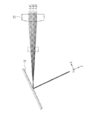
- FIG. 1 shows a simplified configuration of an image display device 101 based on the technique described in Patent Document 1 (Japanese Patent Laid-Open No. 2008-83539).
- the upper stage (A) in FIG. 1 shows the configuration in the XZ plane
- the lower stage (B) in FIG. 1 shows the configuration in the YZ plane.
- Patent Document 1 describes a configuration in which a first diffractive part 111 and a second diffractive part 112 are arranged on a light guide plate, and image light is incident on the light guide plate via the first diffractive part 111. .
- the image light that has entered the light guide plate forms an intermediate image inside the light guide plate, is then guided to the second diffractive portion 112 by the light guide plate, and is emitted from the second diffractive portion 112 toward the observer's eye 100. Is done.
- the second diffractive part 112 is arranged at a symmetrical position with respect to the intermediate image formed after the first diffractive part 111, and is generated by the first diffractive part 111. It corrects curvature of field and spherical aberration in a single wavelength band.
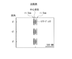
- FIG. 2 is a spot diagram showing the imaging performance of the image display apparatus 101 according to the comparative example.
- FIG. 2 shows a spot diagram on the image plane after the observer's eye 100 is an ideal lens and passes through the ideal lens. The same applies to spot diagrams shown in other figures described later.
- FIG. 2 shows a spot diagram of light having a central wavelength and light having a wavelength of ⁇ 1.5 nm with respect to the central wavelength for a single wavelength band.
- chromatic aberration occurs in the first diffraction unit 111 for a single wavelength band emitted by one light source.
- this chromatic aberration cannot be corrected, and the image is broken on the image plane as shown in FIG.
- Patent Document 2 Japanese Patent Laid-Open No. 11-194295 (FIG. 4) discloses a technique for correcting chromatic aberration caused by arranging a plurality of light sources having different colors with a chromatic aberration generating means such as a diffractive optical element. Has been. However, with the technique described in Patent Document 2, it is difficult to correct chromatic aberration between different wavelengths in the same color (single wavelength band) emitted by one light source.
- the present disclosure provides a technique capable of suppressing chromatic aberration in a single wavelength band.
- a technique capable of suppressing astigmatism and curvature of field is provided.
- an image display device capable of performing high-quality image display is provided.
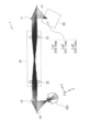
- FIG. 3 shows an overview of the image display device 1 according to the first embodiment of the present disclosure.
- FIG. 3 shows a configuration in the XZ plane.
- the image display device 1 includes an image light forming unit 30 that generates and emits image light.
- the image display device 1 further includes a first diffractive part 11, a second diffractive part 12, a relay optical system 20, and an image light forming part 30.
- the image display device 1 is a device that guides the image light generated by the image light forming unit 30 to the pupil position of the eye 100 of the observer, and can be used as a head-mounted display, for example.
- the image light forming unit 30 has a light source that is a source of image light and a scanning optical element that forms image light by scanning a light beam emitted from the light source.
- FIG. 3 shows optical paths of three wavelengths of light in a single wavelength band (first wavelength light ⁇ g1, second wavelength light ⁇ g2, and third wavelength light ⁇ g3) as optical paths of image light. Show. Normally, light having a wavelength of about ⁇ 1.5 nm is assumed as light in a single wavelength band, but in FIG. 3, the wavelength width is set to be large in order to make the aberration easy to see.
- the second wavelength light ⁇ g2 is illustrated as light having a central wavelength
- light having a wavelength of ⁇ 10 nm with respect to the center wavelength is illustrated as first wavelength light ⁇ g1 and third wavelength light ⁇ g3.
- the second wavelength light ⁇ g2 is, for example, 517.1 nm light
- the first wavelength light ⁇ g1 is, for example, 527.1 nm light
- the third wavelength light ⁇ g3 is, for example, 507.1 nm light.
- the first diffractive portion 11 has a characteristic of correcting chromatic aberration generated in the second diffractive portion 12.
- the first diffractive portion 11 may be, for example, a holographic optical element (HOE).
- the first diffraction section 11 may be a diffraction grating (DOE), for example.
- the second diffractive portion 12 has a role of converging the image light at the pupil position of the observer.
- the second diffractive portion 12 may be, for example, a holographic optical element.
- the second diffractive portion 12 may be a diffraction grating, for example.
- the relay optical system 20 is disposed closer to the image light forming unit 30 than the second diffraction unit 12. Further, the relay optical system 20 has a role of relaying image light from the first diffractive part 11 to the second diffractive part 12 so as to correct chromatic aberration generated in the second diffractive part 12.
- the relay optical system 20 includes a first relay lens 21 and a second relay lens 22.
- FIG. 4 shows an outline of chromatic aberration that occurs in the image display apparatus 1.
- FIG. 5 shows an outline of field curvature that occurs in the image display device 1.
- FIG. 6 shows an outline of astigmatism that occurs in the image display apparatus 1.
- the upper part of FIG. 6 shows the configuration in the XZ plane, and the lower part of FIG. 6 shows the configuration in the YZ plane.
- FIG. 7 shows an outline of spherical aberration that occurs in the image display apparatus 1.
- Chromatic aberration occurs when the image light is deflected in different directions for each wavelength in the second diffraction section 12 (see FIG. 4). It is desirable that light of each wavelength is incident on the observer's eye 100 in a state where they are aligned.
- the curvature of field occurs when the image plane (imaging point) 42 (see FIG. 5) is inclined with respect to the principal ray.
- the image display device 1 has a decentered optical system configuration.
- a diffractive element in a decentered optical system has different power with respect to light incident on a decentered surface and a surface other than the decentered surface. For this reason, a difference occurs between the image formation position in the XZ plane and the image formation position in the YZ plane, resulting in astigmatism.
- astigmatism is caused by the difference in the distance dxz in the XZ plane from the second diffractive portion 12 to the image forming point and the distance dyz in the YZ plane.
- the spherical aberration Sph is generated when light incident at different heights does not form an image at one point in the XZ plane.
- FIG. 8 shows an outline of a method for correcting chromatic aberration and astigmatism occurring in the image display apparatus 1.
- FIG. 9 shows an outline of a method of correcting the field curvature that occurs in the image display device 1.
- the second wavelength light ⁇ g2 is the center wavelength light
- the light having a wavelength of ⁇ 1.5 nm with respect to the center wavelength is the first wavelength light ⁇ g1 and the third wavelength light ⁇ g3. It is shown.
- the second wavelength light ⁇ g2 is, for example, 517.1 nm light
- the first wavelength light ⁇ g1 is, for example, 518.6 nm light
- the third wavelength light ⁇ g3 is, for example, 515.6 nm light.
- the relay optical system 20 is an optical system that relays an image from the first diffraction unit 11 to the second diffraction unit 12.
- the first diffractive part 11, the relay optical system 20, and the second diffractive part 12 are arranged so that the incident angles of the light rays seen from the first diffractive part 11 and the second diffractive part 12 are the same. Deploy. Thereby, chromatic aberration is corrected regardless of the position of the beam waist bw.
- Astigmatism correction can be corrected by adjusting the beam shape (beam diameter, beam divergence angle) incident on the first diffraction section 11. For example, astigmatism can be corrected by adjusting the position of the beam waist bw in the XZ plane and the YZ plane.
- an image plane 41 is formed on the first diffraction section 11 side, and an image plane 42 is formed on the second diffraction section 12 side.
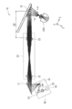
- FIG. 10 shows a configuration of an image display device 1A according to the first specific example of the first embodiment.
- the image light forming unit 30 includes a plurality of optical elements, and a part of the plurality of optical elements is divided into the first diffractive unit 11 and the second diffractive unit 12. It is the composition arranged between.
- the image light forming unit 30 includes a plurality of optical elements and a light source 34.
- the image light forming unit 30 includes a scanning mirror 31 as a plurality of optical elements.
- the image light forming unit 30 may include a correction lens 32 as a plurality of optical elements.
- the correction lens 32 is a correction optical element that corrects astigmatism generated in the second diffraction unit 12.
- the correction lens 32 can be disposed at an arbitrary position between the light source 34 and the scanning mirror 31.
- the light source 34 is a laser light source composed of, for example, a laser diode.
- the scanning mirror 31 is a scanning optical element that forms image light.
- the scanning mirror 31 is composed of, for example, a MEMS (Micro Electro Mechanical Systems) mirror.
- the scanning mirror 31 generates a two-dimensional image light by two-dimensionally scanning the laser light from the light source 34 based on the image data.
- the scanning direction and scanning timing of the scanning mirror 31 are controlled based on the image data.
- the scanning mirror 31 is disposed between the first diffractive part 11 and the second diffractive part 12. Further, the scanning mirror 31 is disposed between the first relay lens 21 and the second relay lens 22 in the relay optical system 20. The first relay lens 21 is disposed between the first diffraction unit 11 and the scanning mirror 31.
- the scanning mirror 31 is disposed between the first diffractive portion 11 and the second diffractive portion 12 as a part of the plurality of optical elements. It has a configuration.
- Astigmatism can be corrected.
- astigmatism can be corrected by adjusting the position of the beam waist bw in the XZ plane and the YZ plane.
- the first diffractive portion 11 causes chromatic aberration as a part of the imaging system together with the first relay lens 21 and the second relay lens 22 of the relay optical system 20. Has the role of correction.
- the second relay lens 22 of the relay optical system 20 has a role of correcting the curvature of field of the second diffractive portion 12.
- the second relay lens 22 is disposed at such a position and inclination that the light at each angle of view is an optimal image formation position and the inclination of the image plane 42 is optimal as viewed from the second diffraction section 12. It is desirable.
- the distance D1 between the second relay lens 22 and the second diffractive portion 12 is desirably set to a value such that light other than light from the second diffractive portion 12 does not enter the observer's field of view. Accordingly, it is desirable that the second relay lens 22 is not visible in the observer's field of view.
- the distance D1 is preferably set so that the observer's head does not interfere with the optical system of the image display apparatus 1A.
- the entrance pupil of the image display apparatus 1A according to the first specific example is 0.5 mm, for example.
- the angle of view is, for example, ⁇ 20 °.
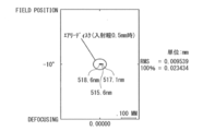
- FIGS. 11 to 15 are spot diagrams showing the imaging performance of the image display apparatus 1A according to the first specific example.
- 11 shows an angle of view of ⁇ 20 °
- FIG. 12 shows an angle of view of ⁇ 10 °
- FIG. 13 shows an angle of view of 0 °
- FIG. 14 shows an angle of view of + 10 °
- the angle of view here indicates the angle of view ⁇ in the X direction in FIG. 10.
- the angle of view ⁇ is ⁇ (minus) the angle of light incident on the observer's eye 100 from the left side with respect to the Z-direction axis (optical axis), and the observer's eye 100 from the right side.
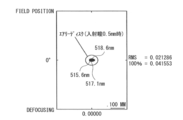
- FIGS. 11 to 15 show spot diagrams of light having a center wavelength (517.1 nm) and light having a wavelength of ⁇ 1.5 nm with respect to the center wavelength for a single wavelength band.
- the chromatic aberration is corrected well.
- FIG. 16 shows a configuration of an image display device 1B according to a second specific example in the first embodiment.
- the image display device 1B according to the second specific example has a light guide plate 13 that guides the image light emitted from the relay optical system 20 to the second diffractive portion 12 with respect to the image display device 1A according to the first specific example. It has.
- the light guide plate 13 has a first surface 13A and a second surface 13B facing each other.
- a prism 14 is disposed on the second surface 13B of the light guide plate 13.
- the prism 14 has a role of causing image light to enter the light guide plate 13.
- the prism 14 can have a role of adjusting the optical path length of each pixel.
- the second diffractive portion 12 is disposed on either one of the first surface 13A and the second surface 13B of the light guide plate. In FIG. 16, the second diffractive portion 12 is arranged on the first surface 13A.
- FIG. 17 shows a configuration of an image display device 1C according to a third specific example of the first embodiment.
- the image display device 1C according to the third specific example is different from the image display device 1A according to the first specific example in that the entire image light forming unit 30 and the first diffraction unit 11 are In this configuration, the second diffractive portion 12 is arranged farther away.
- the image display apparatus 1C includes a scanning mirror 31, a correction lens 32, and a reflection mirror 33 as a plurality of optical elements.
- the reflection mirror 33 has a role of reflecting light from the light source 34 toward the scanning mirror 31.
- the scanning mirror 31 is arranged in front of the first diffraction unit 11 (distant from the observer).
- the image light after being emitted from the scanning mirror 31 is incident on the first diffraction unit 11.
- the first diffractive portion 11 and the second diffractive portion 12 are configured by diffractive elements having optically the same action, and symmetrically in the XZ plane. By disposing, chromatic aberration can be corrected satisfactorily.
- the entrance pupil of the image display apparatus 1C according to the third specific example is 0.5 mm, for example.
- the angle of view is, for example, ⁇ 20 °.
- FIG. 18 is a spot diagram showing the imaging performance of the image display device 1C according to the third specific example.
- FIG. 18 shows a spot diagram of light having a center wavelength (517.1 nm) and light having a wavelength of ⁇ 1.5 nm with respect to the center wavelength for a single wavelength band.
- FIG. 18 shows a spot diagram in a field angle range of ⁇ 20 ° to + 20 °.
- the angle of view referred to here indicates the angle of view ⁇ in the X direction in FIG.
- the angle of view ⁇ is ⁇ (minus) the angle of light incident on the observer's eye 100 from the left side with respect to the Z-direction axis (optical axis), and the observer's eye 100 from the right side. Assume that the angle of light incident on is + (plus).
- the chromatic aberration is corrected well.
- FIG. 19 shows a configuration of an image display device 1D according to a fourth specific example of the first embodiment.
- the image display device 1D according to the fourth specific example is different from the image display device 1C according to the third specific example between the image light forming unit 30 (scanning mirror 31) and the first diffraction unit 11.
- the collimator lens 51 is arranged.
- the collimator lens 51 Since the first diffractive portion 11 is an element that diffracts parallel light into parallel light, the collimator lens 51 has a role of making image light formed by the scanning mirror 31 parallel light.
- the entrance pupil of the image display device 1D according to the fourth specific example is 0.5 mm, for example.
- the angle of view is, for example, ⁇ 20 °.
- FIG. 20 is a spot diagram showing the imaging performance of the image display device 1D according to the fourth specific example.
- FIG. 20 shows a spot diagram of light having a center wavelength (517.1 nm) and light having a wavelength of ⁇ 1.5 nm with respect to the center wavelength for a single wavelength band.
- FIG. 20 shows a spot diagram in a field angle range of ⁇ 20 ° to + 20 °.
- the angle of view here indicates the angle of view ⁇ in the X direction in FIG. 19.
- the angle of view ⁇ is ⁇ (minus) of the angle of light incident on the observer's eye 100 from the left side with respect to the Z direction axis (optical axis), and the observer's eye 100 from the right side. Assume that the angle of the light beam incident on is + (plus).
- the chromatic aberration is corrected well.
- FIG. 21 shows a configuration of an image display device 1E according to a fifth specific example of the first embodiment.
- the image display device 1E according to the fifth specific example includes a relay optical system 20A instead of the relay optical system 20 with respect to the image display device 1C according to the third specific example.
- the relay optical system 20 in the image display apparatus 1C according to the third specific example is an optical system in which the first relay lens 21 and the second relay lens 22 are equal in magnification.
- the relay optical system 20A in the image display apparatus 1E according to the fifth specific example the first relay lens 21A and the second relay lens 22A are enlarged optical systems.
- the image light forming unit 30 forms image light with an angle of view of ⁇ 20 °.
- the relay optical system 20A enlarges the angle of view to ⁇ 40 °, for example. Thereby, a wide angle of view is achieved.
- FIG. 22 shows a configuration of an image display device 1F according to a sixth specific example of the first embodiment.
- the image display device 1F according to the sixth specific example includes a relay optical system 20B instead of the relay optical system 20 with respect to the image display device 1C according to the third specific example.
- the relay optical system 20B in the image display device 1F according to the sixth specific example includes a reflective optical element 23 and a reflective optical element 24 that fold the optical path between the first relay lens 21 and the second relay lens 22. I have.
- the reflective optical element 23 and the reflective optical element 24 can be constituted by, for example, a reflective mirror or a prism.
- the optical path can be folded by the reflective optical element 23 and the reflective optical element 24, whereby the size can be reduced. Further, for example, when applied to a head mounted display, it becomes easy to have a configuration that fits around the face of the observer.
- FIG. 23 shows a configuration of an image display apparatus 1G according to the seventh specific example of the first embodiment.
- the image display device 1G according to the seventh specific example has a configuration corresponding to, for example, full-color display of R (red), G (green), and B (blue).
- the image display device 1G according to the seventh specific example includes a relay optical system 20C instead of the relay optical system 20 with respect to the image display device 1C according to the third specific example.
- the relay optical system 20C includes a first relay lens 21B and a second relay lens 22B corresponding to full color display.
- the first relay lens 21B and the second relay lens 22B are composed of achromatic lenses and have an action of correcting aberrations between a plurality of colors.
- each of the first diffractive portion 11 and the second diffractive portion 12 receives image lights of a plurality of colors having different wavelength bands corresponding to full color display.
- a structure in which a plurality of diffraction patterns are stacked, a structure in which a plurality of diffraction patterns are multiplexed, or a structure in which these stacked structures are combined with a multiplexed structure so as to converge toward the pupil position have.
- the chromatic aberration generated in the second diffractive part 12 is corrected by the first diffractive part 11 and the relay optical system 20. Therefore, high-quality image display with suppressed chromatic aberration can be performed.
- the image display device has the following effects.
- the curvature of field generated in the second diffractive portion 12 is corrected, and a high-quality image can be obtained.
- the optical system can be downsized (FIG. 10 and the like).
- the magnification of the relay optical system 20A the angle of view emitted from the image light forming unit 30 can be widened (FIG. 21).
- a shape suitable for eyewear can be obtained (FIG. 22).
- the magnification of the relay optical system 20 and the focal length of the relay lens the length of the relay optical system 20 can be shortened, and the size can be reduced.
- the image display device relates to a configuration example that enables image display according to the movement of the pupil position with respect to the image display device according to the first embodiment.
- the image display device includes a detection unit that detects the pupil position of the observer, and a control unit that moves the convergence position of the image light to the pupil position of the observer based on the detection result of the detection unit. And further.
- a detection unit that detects the pupil position of the observer
- a control unit that moves the convergence position of the image light to the pupil position of the observer based on the detection result of the detection unit.
- FIG. 24 shows a configuration of an image display device 1H according to the first specific example of the second embodiment.
- the image display device 1H includes a position detection unit 61 and a drive control unit 62.
- the position detector 61 is a detector that detects the pupil position of the observer.
- the drive control unit 62 is a control unit that moves the convergence position of the image light to the pupil position of the observer based on the detection result of the position detection unit 61.
- the drive control unit 62 moves the second diffraction unit 12 in at least one movement direction corresponding to the horizontal direction of the observer's visual field, the vertical direction of the observer's visual field, and the depth direction of the observer's eyeball.
- the convergence position of the image light is moved to the pupil position of the observer.
- Lb indicates the region of the second diffractive portion 12 used for one condensing point.
- FIG. 25 shows a configuration of an image display device 1I according to a second specific example of the second embodiment.
- the image display device 1I includes a position detection unit 61 and a drive control unit 63.
- the drive control unit 63 is a control unit that moves the convergence position of the image light to the pupil position of the observer based on the detection result of the position detection unit 61.
- the drive control unit 63 moves the image light forming unit 30 (the entire image light forming unit 30 or the scanning mirror 31) in the horizontal direction of the observer's visual field, the vertical direction of the observer's visual field, and the depth of the observer's eyeball. By moving in at least one moving direction corresponding to the direction, the convergence position of the image light is moved to the pupil position of the observer.
- FIG. 26 shows a configuration of an image display device 1J according to a third specific example in the second embodiment.
- the image display device 1J includes a position detection unit 61 and a drive control unit 64. Further, the image display device 1 ⁇ / b> J includes a movable reflection mirror 35.
- the movable reflecting mirror 35 is a movable reflecting element capable of moving the convergence position of the image light by changing the arrangement angle.
- the movable reflecting mirror 35 is disposed on the optical path of the image light emitted from the image light forming unit 30.
- the movable reflection mirror 35 is disposed between the image light forming unit 30 and the second diffraction unit 12.
- the drive control unit 64 moves the convergence position of the image light to the pupil position of the observer by changing the arrangement angle of the movable reflecting mirror 35 based on the detection result of the position detection unit 61.
- FIG. 27 illustrates an overview of an image display device 1K according to the third embodiment of the present disclosure.
- the image display device 1K according to the third embodiment is different from the image display device 1 according to the first embodiment (FIG. 3) in that the first diffractive portion 11 is replaced with the first diffractive element 71. 2 diffractive elements 72.
- the image display device 1 ⁇ / b> K according to the third embodiment includes a collimator lens 80 on the optical path between the first diffractive element 71 and the second diffractive element 72.
- the first diffraction element 71 has a characteristic of correcting chromatic aberration generated in the second diffraction unit 12.
- the first diffraction element 71 is a transmission type diffraction element.
- the first diffractive element 71 may be, for example, a holographic optical element.
- the first diffraction element 71 may be a diffraction grating (DOE), for example.
- DOE diffraction grating
- the second diffractive element 72 is arranged on the optical path between the first diffractive element 71 and the second diffractive portion 12 and has a function of converging the image light emitted from the first diffractive element 71.
- the second diffraction element 72 is a transmission type diffraction element.
- the second diffractive element 72 may be, for example, a holographic optical element.
- the second diffraction element 72 may be a diffraction grating, for example.
- the collimator lens 80 and the second diffractive element 72 constitute a relay optical system 20D that relays the image light from the image light forming part 30 from the first diffractive element 71 to the second diffractive part 12. That is, the second diffraction element 72 constitutes a part of the relay optical system 20D.
- the first diffractive portion 11 is composed of the first diffractive element 71 and the second diffractive element 72, so that the first It is not necessary to arrange the diffraction element 71 at a conjugate position.
- the image light from the image light forming unit 30 is dispersed by the first diffraction element 71 so as to cancel the chromatic aberration generated in the second diffraction unit 12.
- FIG. 27 shows the first wavelength light ⁇ g1, the second wavelength light ⁇ g2, and the third wavelength light ⁇ g3 as examples of the dispersed wavelength components.
- the angle of the dispersed light is adjusted by the collimator lens 80 and the second diffractive element 72 so as to have an appropriate incident angle for each wavelength with respect to the second diffractive portion 12.
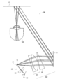
- FIG. 28 shows the configuration of an image display device 1L according to the first specific example of the third embodiment.
- the image light forming unit 30 includes a light source (not shown), a scanning mirror 31, a reflecting mirror 33, and a lens 36.
- the lens 36 is, for example, a toroidal lens.
- an imaging lens 81 and a prism 82 are disposed on the optical path between the first diffraction element 71 and the second diffraction element 72.
- the first diffractive element 71 is disposed on the optical path between the scanning mirror 31 and the imaging lens 82.
- the second diffractive element 72, the imaging lens 81 and the prism 82 constitute a relay optical system 20E.
- each of the first diffraction element 71 and the second diffraction element 72 is a transmission type diffraction element.
- FIG. 29 shows a configuration of an image display device 1M according to a second specific example of the third embodiment.
- FIG. 30 shows a configuration of an image display device 1N according to a third specific example of the third embodiment.
- the first diffraction element 71 is placed in front of the scanning mirror 31 in the image light forming unit 30.
- Arrangement such as arrangement is also possible.
- Other configurations may be substantially the same as the configuration of the image display device 1L according to the first specific example shown in FIG.
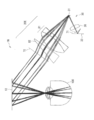
- FIG. 31 shows a configuration of an image display device 1O according to a fourth specific example of the third embodiment.
- a configuration using a spherical mirror optical system is also possible for the configuration of the image display apparatus 1L according to the first specific example shown in FIG.
- a configuration using a plurality of concave mirrors 83A, 83B, 83C is also possible.
- the first diffraction element 71 is disposed on an optical path between a light source (not shown) and the scanning mirror 31.
- the first diffraction element 71 is a reflection type diffraction element
- the second diffraction element 72 is a transmission type diffraction element.
- a plurality of concave mirrors 83A, 83B, and 83C are disposed on the optical path between the scanning mirror 31 and the second diffraction element 72.
- the second diffraction element 72 and the plurality of concave mirrors 83A, 83B, 83C constitute a relay optical system 20F.
- FIG. 32 shows an outline of an image display device 1P according to a modification to the image display device 1K according to the third embodiment shown in FIG.
- the first diffractive portion 11 may be configured by three or more diffractive elements.
- FIG. 32 shows an example in which the first diffractive portion 11 is composed of a first diffractive element 71, a second diffractive element 72, and a third diffractive element 73.
- the first to third diffraction elements 71 to 73 are transmissive diffraction elements.
- the first to third diffraction elements 71 to 73 may be holographic optical elements, for example.
- the second diffractive element 72 and the third diffractive element 73 have an action of converging image light emitted from the first diffractive element 71 in the image display device 1P according to the modification shown in FIG.
- the first diffractive portion 11 is configured by a plurality of diffractive elements, chromatic aberration is improved while maintaining a degree of freedom in design.
- the image quality can be further improved.
- the degree of freedom in optical design is increased, so that the optical system can be downsized.
- a plurality of second diffraction sections 12 may be provided in the configuration of the image display device 1B shown in FIG.
- a plurality of second diffraction sections 12 for different wavelength bands may be provided.
- the second diffractive portion 12 for red display is arranged on one of the first surface 13A and the second surface 13B of the light guide plate 13, and green and blue are displayed on the other surface.
- a second diffractive portion 12 may be disposed.
- the technology according to the present disclosure is applicable not only to a head mounted display but also to a projector.
- this technique can also take the following structures.
- chromatic aberration generated in the second diffractive portion is corrected by the first diffractive portion and the relay optical system, so that high-quality image display with suppressed chromatic aberration is performed. Is possible.
- An image light forming section for emitting image light; A first diffractive part having at least one diffractive element; and a second diffractive part for converging the image light to a pupil position of an observer, wherein the first diffractive part is the second diffractive part.
- a diffractive optical system having a characteristic for correcting the generated chromatic aberration, and A relay optical system that is disposed closer to the image light forming unit than the second diffractive unit and relays the image light to the second diffractive unit so as to correct chromatic aberration generated in the second diffractive unit.
- An image display device comprising: (2) The first diffractive portion has a characteristic of generating chromatic aberration that is optically symmetric with respect to the second diffractive portion with respect to at least a part of light incident on the second diffractive portion.
- the image light forming unit includes a plurality of optical elements, and a part of the plurality of optical elements is disposed between the first diffractive unit and the second diffractive unit (1) Or the image display apparatus as described in (2).
- the image light forming unit includes a scanning optical element that forms the image light as the plurality of optical elements, and the scanning optical element is disposed between the first diffraction unit and the second diffraction unit.
- the image light forming unit is entirely disposed farther than the first diffractive unit and the second diffractive unit as viewed from the observer.
- Each of the first diffractive part and the second diffractive part is formed by laminating a plurality of diffraction patterns so as to converge a plurality of image lights having different wavelength bands toward the pupil position of the observer.
- the image display device having a structure, a structure in which a plurality of diffraction patterns are multiplexed, or a structure in which the stacked structure and the multiplexed structure are combined .
- the image display according to any one of (1) to (7), further including: a control unit that moves the convergence position of the image light to the pupil position of the observer by moving in one moving direction. apparatus.
- a detection unit for detecting a pupil position of the observer Based on the detection result of the detection unit, the image light forming unit is at least one corresponding to a horizontal direction of the observer's visual field, a vertical direction of the observer's visual field, and a depth direction of the observer's eyeball.
- the image display device according to any one of (1) to (7), further including: a control unit that moves the convergence position of the image light to the pupil position of the observer by moving in one moving direction. .
- the image light forming unit A light source;
- a movable reflective element capable of moving the convergence position of the image light by changing the arrangement angle;
- the image display device according to any one of (1) to (10).
- (12) A detection unit for detecting a pupil position of the observer; (11) further comprising: a control unit that moves the convergence position of the image light to the pupil position of the observer by changing an arrangement angle of the movable reflective element based on a detection result of the detection unit.
- (14) The image display device according to (13), wherein the movable reflective element is disposed between the image light forming unit and the second diffraction unit.
- the light guide plate has a first surface and a second surface facing each other, The image display device according to (15), wherein the second diffractive portion is disposed on one of the first surface and the second surface of the light guide plate.
- the first diffraction part is: A first diffractive element having a characteristic of correcting chromatic aberration generated in the second diffractive portion; (2) a second diffractive element disposed on an optical path between the first diffractive element and the second diffractive portion and converging the image light emitted from the first diffractive element. ) Or (2).
- the first diffraction element is a transmission type diffraction element, The image display apparatus according to (17) or (18), wherein the second diffractive element is a transmissive or reflective diffractive element.
- the first diffractive element is a reflective diffractive element, The image display apparatus according to (17) or (18), wherein the second diffractive element is a transmissive or reflective diffractive element.
Landscapes
- Physics & Mathematics (AREA)
- General Physics & Mathematics (AREA)
- Optics & Photonics (AREA)
- Health & Medical Sciences (AREA)
- Ophthalmology & Optometry (AREA)
- General Health & Medical Sciences (AREA)
- Lenses (AREA)
Priority Applications (5)
| Application Number | Priority Date | Filing Date | Title |
|---|---|---|---|
| JP2020523656A JPWO2019235320A1 (ja) | 2018-06-08 | 2019-05-29 | 画像表示装置 |
| CN201980036892.1A CN112219152B (zh) | 2018-06-08 | 2019-05-29 | 图像显示装置 |
| EP19815671.3A EP3805847A4 (en) | 2018-06-08 | 2019-05-29 | IMAGE DISPLAY DEVICE |
| US15/733,984 US12025810B2 (en) | 2018-06-08 | 2019-05-29 | Image display apparatus |
| KR1020207030242A KR102785589B1 (ko) | 2018-06-08 | 2019-05-29 | 화상 표시 장치 |
Applications Claiming Priority (4)
| Application Number | Priority Date | Filing Date | Title |
|---|---|---|---|
| JP2018-110305 | 2018-06-08 | ||
| JP2018110305 | 2018-06-08 | ||
| JP2019-087456 | 2019-05-07 | ||
| JP2019087456 | 2019-05-07 |
Publications (1)
| Publication Number | Publication Date |
|---|---|
| WO2019235320A1 true WO2019235320A1 (ja) | 2019-12-12 |
Family
ID=68769521
Family Applications (1)
| Application Number | Title | Priority Date | Filing Date |
|---|---|---|---|
| PCT/JP2019/021293 Ceased WO2019235320A1 (ja) | 2018-06-08 | 2019-05-29 | 画像表示装置 |
Country Status (6)
| Country | Link |
|---|---|
| US (1) | US12025810B2 (https=) |
| EP (1) | EP3805847A4 (https=) |
| JP (1) | JPWO2019235320A1 (https=) |
| KR (1) | KR102785589B1 (https=) |
| CN (1) | CN112219152B (https=) |
| WO (1) | WO2019235320A1 (https=) |
Cited By (2)
| Publication number | Priority date | Publication date | Assignee | Title |
|---|---|---|---|---|
| WO2021220638A1 (ja) * | 2020-04-28 | 2021-11-04 | ソニーグループ株式会社 | 表示装置 |
| WO2026014383A1 (ja) * | 2024-07-12 | 2026-01-15 | パナソニックIpマネジメント株式会社 | 光学系、及び画像表示装置 |
Citations (13)
| Publication number | Priority date | Publication date | Assignee | Title |
|---|---|---|---|---|
| JPH11194295A (ja) | 1997-11-06 | 1999-07-21 | Olympus Optical Co Ltd | 光学系 |
| JP2001264685A (ja) * | 2000-03-23 | 2001-09-26 | Canon Inc | 画像表示装置および画像表示システム |
| JP2008083539A (ja) | 2006-09-28 | 2008-04-10 | Brother Ind Ltd | 光束転送用の光学系、及び、これを用いた網膜走査型ディスプレイ |
| JP2008145701A (ja) * | 2006-12-08 | 2008-06-26 | Canon Inc | 画像表示装置及び画像表示システム |
| JP2010117542A (ja) * | 2008-11-13 | 2010-05-27 | Panasonic Corp | ビーム走査型表示装置 |
| JP2016170203A (ja) * | 2015-03-11 | 2016-09-23 | コニカミノルタ株式会社 | 画像表示装置 |
| US9529196B1 (en) * | 2014-06-05 | 2016-12-27 | Iphysicist Ltd. | Image guide optics for near eye displays |
| JP2017167181A (ja) * | 2016-03-14 | 2017-09-21 | セイコーエプソン株式会社 | 表示装置および導光装置 |
| WO2018031634A1 (en) * | 2016-08-10 | 2018-02-15 | FictionArt, Inc. | Volume phase holographic waveguide for display |
| WO2018043625A1 (ja) * | 2016-08-31 | 2018-03-08 | パナソニックIpマネジメント株式会社 | 表示装置 |
| JP2018087949A (ja) * | 2016-11-30 | 2018-06-07 | セイコーエプソン株式会社 | 映像表示装置、および導光装置 |
| JP2018110305A (ja) | 2016-12-28 | 2018-07-12 | 京セラドキュメントソリューションズ株式会社 | 画像形成装置 |
| JP2019087456A (ja) | 2017-11-08 | 2019-06-06 | ホシデン株式会社 | コネクタ |
Family Cites Families (7)
| Publication number | Priority date | Publication date | Assignee | Title |
|---|---|---|---|---|
| JP4082075B2 (ja) * | 2002-04-22 | 2008-04-30 | ブラザー工業株式会社 | 画像表示装置 |
| JP6111864B2 (ja) * | 2013-05-24 | 2017-04-12 | 富士通株式会社 | 画像表示装置及び画像表示方法 |
| JP6413291B2 (ja) * | 2014-03-27 | 2018-10-31 | セイコーエプソン株式会社 | 虚像表示装置、およびヘッドマウントディスプレイ |
| US9904057B2 (en) * | 2015-08-31 | 2018-02-27 | Seiko Epson Corporation | Light guide device and virtual image display apparatus |
| JP2017058400A (ja) * | 2015-09-14 | 2017-03-23 | コニカミノルタ株式会社 | 画像表示装置 |
| CN106646870B (zh) * | 2016-09-27 | 2018-12-28 | 东南大学 | 一种全息波导显示系统及显示方法 |
| JP2018054978A (ja) * | 2016-09-30 | 2018-04-05 | セイコーエプソン株式会社 | 虚像表示装置及びその製造方法 |
-
2019
- 2019-05-29 EP EP19815671.3A patent/EP3805847A4/en not_active Withdrawn
- 2019-05-29 JP JP2020523656A patent/JPWO2019235320A1/ja active Pending
- 2019-05-29 US US15/733,984 patent/US12025810B2/en active Active
- 2019-05-29 KR KR1020207030242A patent/KR102785589B1/ko active Active
- 2019-05-29 WO PCT/JP2019/021293 patent/WO2019235320A1/ja not_active Ceased
- 2019-05-29 CN CN201980036892.1A patent/CN112219152B/zh active Active
Patent Citations (13)
| Publication number | Priority date | Publication date | Assignee | Title |
|---|---|---|---|---|
| JPH11194295A (ja) | 1997-11-06 | 1999-07-21 | Olympus Optical Co Ltd | 光学系 |
| JP2001264685A (ja) * | 2000-03-23 | 2001-09-26 | Canon Inc | 画像表示装置および画像表示システム |
| JP2008083539A (ja) | 2006-09-28 | 2008-04-10 | Brother Ind Ltd | 光束転送用の光学系、及び、これを用いた網膜走査型ディスプレイ |
| JP2008145701A (ja) * | 2006-12-08 | 2008-06-26 | Canon Inc | 画像表示装置及び画像表示システム |
| JP2010117542A (ja) * | 2008-11-13 | 2010-05-27 | Panasonic Corp | ビーム走査型表示装置 |
| US9529196B1 (en) * | 2014-06-05 | 2016-12-27 | Iphysicist Ltd. | Image guide optics for near eye displays |
| JP2016170203A (ja) * | 2015-03-11 | 2016-09-23 | コニカミノルタ株式会社 | 画像表示装置 |
| JP2017167181A (ja) * | 2016-03-14 | 2017-09-21 | セイコーエプソン株式会社 | 表示装置および導光装置 |
| WO2018031634A1 (en) * | 2016-08-10 | 2018-02-15 | FictionArt, Inc. | Volume phase holographic waveguide for display |
| WO2018043625A1 (ja) * | 2016-08-31 | 2018-03-08 | パナソニックIpマネジメント株式会社 | 表示装置 |
| JP2018087949A (ja) * | 2016-11-30 | 2018-06-07 | セイコーエプソン株式会社 | 映像表示装置、および導光装置 |
| JP2018110305A (ja) | 2016-12-28 | 2018-07-12 | 京セラドキュメントソリューションズ株式会社 | 画像形成装置 |
| JP2019087456A (ja) | 2017-11-08 | 2019-06-06 | ホシデン株式会社 | コネクタ |
Non-Patent Citations (1)
| Title |
|---|
| See also references of EP3805847A4 |
Cited By (3)
| Publication number | Priority date | Publication date | Assignee | Title |
|---|---|---|---|---|
| WO2021220638A1 (ja) * | 2020-04-28 | 2021-11-04 | ソニーグループ株式会社 | 表示装置 |
| US12498562B2 (en) | 2020-04-28 | 2025-12-16 | Sony Group Corporation | Display apparatus |
| WO2026014383A1 (ja) * | 2024-07-12 | 2026-01-15 | パナソニックIpマネジメント株式会社 | 光学系、及び画像表示装置 |
Also Published As
| Publication number | Publication date |
|---|---|
| CN112219152A (zh) | 2021-01-12 |
| CN112219152B (zh) | 2023-10-03 |
| JPWO2019235320A1 (ja) | 2021-06-24 |
| EP3805847A4 (en) | 2021-10-27 |
| US20210215939A1 (en) | 2021-07-15 |
| KR102785589B1 (ko) | 2025-03-21 |
| EP3805847A1 (en) | 2021-04-14 |
| KR20210018198A (ko) | 2021-02-17 |
| US12025810B2 (en) | 2024-07-02 |
Similar Documents
| Publication | Publication Date | Title |
|---|---|---|
| US11520158B2 (en) | Display device | |
| JP7170652B2 (ja) | ニアアイビューイング用ウェアラブルディスプレイ | |
| JP5229327B2 (ja) | 映像表示装置、ヘッドマウントディスプレイおよびヘッドアップディスプレイ | |
| US10921598B2 (en) | Image projection device | |
| CN111065954B (zh) | 弯曲光导、成像光学单元以及hmd | |
| WO2016051706A1 (ja) | 画像表示装置 | |
| JP2019133132A (ja) | 表示装置 | |
| KR102875632B1 (ko) | 디스플레이용 광학 배열체 | |
| JP4082075B2 (ja) | 画像表示装置 | |
| JP6794738B2 (ja) | 頭部装着型表示装置 | |
| JP2020071369A (ja) | 表示装置 | |
| WO2014077032A1 (ja) | 表示装置 | |
| WO2016185992A1 (ja) | 表示装置 | |
| JP5901321B2 (ja) | 画像表示装置 | |
| KR102785589B1 (ko) | 화상 표시 장치 | |
| JP2013148609A (ja) | 網膜投影表示装置 | |
| JP2020071417A (ja) | 表示装置 | |
| JP2020071416A (ja) | 表示装置 | |
| EP3726261A1 (en) | Optical arrangement for a display | |
| WO2023119962A1 (ja) | 画像表示装置、導光板、及び画像表示方法 | |
| WO2025057765A1 (ja) | 投影光学系、画像投影装置、および接眼デバイス |
Legal Events
| Date | Code | Title | Description |
|---|---|---|---|
| 121 | Ep: the epo has been informed by wipo that ep was designated in this application |
Ref document number: 19815671 Country of ref document: EP Kind code of ref document: A1 |
|
| ENP | Entry into the national phase |
Ref document number: 2020523656 Country of ref document: JP Kind code of ref document: A |
|
| NENP | Non-entry into the national phase |
Ref country code: DE |
|
| ENP | Entry into the national phase |
Ref document number: 2019815671 Country of ref document: EP Effective date: 20210111 |
|
| WWW | Wipo information: withdrawn in national office |
Ref document number: 2019815671 Country of ref document: EP |