WO2019230893A1 - 箱詰装置 - Google Patents
箱詰装置 Download PDFInfo
- Publication number
- WO2019230893A1 WO2019230893A1 PCT/JP2019/021552 JP2019021552W WO2019230893A1 WO 2019230893 A1 WO2019230893 A1 WO 2019230893A1 JP 2019021552 W JP2019021552 W JP 2019021552W WO 2019230893 A1 WO2019230893 A1 WO 2019230893A1
- Authority
- WO
- WIPO (PCT)
- Prior art keywords
- hand
- holding
- box
- gripping
- arm
- Prior art date
- Legal status (The legal status is an assumption and is not a legal conclusion. Google has not performed a legal analysis and makes no representation as to the accuracy of the status listed.)
- Ceased
Links
Images






Classifications
-
- B—PERFORMING OPERATIONS; TRANSPORTING
- B65—CONVEYING; PACKING; STORING; HANDLING THIN OR FILAMENTARY MATERIAL
- B65B—MACHINES, APPARATUS OR DEVICES FOR, OR METHODS OF, PACKAGING ARTICLES OR MATERIALS; UNPACKING
- B65B43/00—Forming, feeding, opening or setting-up containers or receptacles in association with packaging
- B65B43/26—Opening or distending bags; Opening, erecting, or setting-up boxes, cartons, or carton blanks
- B65B43/30—Opening or distending bags; Opening, erecting, or setting-up boxes, cartons, or carton blanks by grippers engaging opposed walls, e.g. suction-operated
-
- B—PERFORMING OPERATIONS; TRANSPORTING
- B65—CONVEYING; PACKING; STORING; HANDLING THIN OR FILAMENTARY MATERIAL
- B65B—MACHINES, APPARATUS OR DEVICES FOR, OR METHODS OF, PACKAGING ARTICLES OR MATERIALS; UNPACKING
- B65B43/00—Forming, feeding, opening or setting-up containers or receptacles in association with packaging
- B65B43/26—Opening or distending bags; Opening, erecting, or setting-up boxes, cartons, or carton blanks
- B65B43/30—Opening or distending bags; Opening, erecting, or setting-up boxes, cartons, or carton blanks by grippers engaging opposed walls, e.g. suction-operated
- B65B43/305—Opening or distending bags; Opening, erecting, or setting-up boxes, cartons, or carton blanks by grippers engaging opposed walls, e.g. suction-operated specially adapted for boxes, cartons or carton blanks
-
- B—PERFORMING OPERATIONS; TRANSPORTING
- B25—HAND TOOLS; PORTABLE POWER-DRIVEN TOOLS; MANIPULATORS
- B25J—MANIPULATORS; CHAMBERS PROVIDED WITH MANIPULATION DEVICES
- B25J15/00—Gripping heads and other end effectors
- B25J15/0052—Gripping heads and other end effectors multiple gripper units or multiple end effectors
- B25J15/0066—Gripping heads and other end effectors multiple gripper units or multiple end effectors with different types of end effectors, e.g. gripper and welding gun
-
- B—PERFORMING OPERATIONS; TRANSPORTING
- B25—HAND TOOLS; PORTABLE POWER-DRIVEN TOOLS; MANIPULATORS
- B25J—MANIPULATORS; CHAMBERS PROVIDED WITH MANIPULATION DEVICES
- B25J15/00—Gripping heads and other end effectors
- B25J15/06—Gripping heads and other end effectors with vacuum or magnetic holding means
- B25J15/0616—Gripping heads and other end effectors with vacuum or magnetic holding means with vacuum
-
- B—PERFORMING OPERATIONS; TRANSPORTING
- B25—HAND TOOLS; PORTABLE POWER-DRIVEN TOOLS; MANIPULATORS
- B25J—MANIPULATORS; CHAMBERS PROVIDED WITH MANIPULATION DEVICES
- B25J15/00—Gripping heads and other end effectors
- B25J15/08—Gripping heads and other end effectors having finger members
-
- B—PERFORMING OPERATIONS; TRANSPORTING
- B25—HAND TOOLS; PORTABLE POWER-DRIVEN TOOLS; MANIPULATORS
- B25J—MANIPULATORS; CHAMBERS PROVIDED WITH MANIPULATION DEVICES
- B25J9/00—Program-controlled manipulators
- B25J9/0084—Program-controlled manipulators comprising a plurality of manipulators
- B25J9/0087—Dual arms
-
- B—PERFORMING OPERATIONS; TRANSPORTING
- B25—HAND TOOLS; PORTABLE POWER-DRIVEN TOOLS; MANIPULATORS
- B25J—MANIPULATORS; CHAMBERS PROVIDED WITH MANIPULATION DEVICES
- B25J9/00—Program-controlled manipulators
- B25J9/0093—Program-controlled manipulators co-operating with conveyor means
-
- B—PERFORMING OPERATIONS; TRANSPORTING
- B25—HAND TOOLS; PORTABLE POWER-DRIVEN TOOLS; MANIPULATORS
- B25J—MANIPULATORS; CHAMBERS PROVIDED WITH MANIPULATION DEVICES
- B25J9/00—Program-controlled manipulators
- B25J9/02—Program-controlled manipulators characterised by movement of the arms, e.g. cartesian coordinate type
- B25J9/04—Program-controlled manipulators characterised by movement of the arms, e.g. cartesian coordinate type by rotating at least one arm, excluding the head movement itself, e.g. cylindrical coordinate type or polar coordinate type
- B25J9/041—Cylindrical coordinate type
- B25J9/042—Cylindrical coordinate type comprising an articulated arm
- B25J9/043—Cylindrical coordinate type comprising an articulated arm double selective compliance articulated robot arms [SCARA]
-
- B—PERFORMING OPERATIONS; TRANSPORTING
- B25—HAND TOOLS; PORTABLE POWER-DRIVEN TOOLS; MANIPULATORS
- B25J—MANIPULATORS; CHAMBERS PROVIDED WITH MANIPULATION DEVICES
- B25J9/00—Program-controlled manipulators
- B25J9/06—Program-controlled manipulators characterised by multi-articulated arms
-
- B—PERFORMING OPERATIONS; TRANSPORTING
- B25—HAND TOOLS; PORTABLE POWER-DRIVEN TOOLS; MANIPULATORS
- B25J—MANIPULATORS; CHAMBERS PROVIDED WITH MANIPULATION DEVICES
- B25J9/00—Program-controlled manipulators
- B25J9/16—Program controls
- B25J9/1656—Program controls characterised by programming, planning systems for manipulators
- B25J9/1669—Program controls characterised by programming, planning systems for manipulators characterised by special application, e.g. multi-arm co-operation, assembly, grasping
-
- B—PERFORMING OPERATIONS; TRANSPORTING
- B65—CONVEYING; PACKING; STORING; HANDLING THIN OR FILAMENTARY MATERIAL
- B65B—MACHINES, APPARATUS OR DEVICES FOR, OR METHODS OF, PACKAGING ARTICLES OR MATERIALS; UNPACKING
- B65B35/00—Supplying, feeding, arranging or orientating articles to be packaged
- B65B35/10—Feeding, e.g. conveying, single articles
- B65B35/16—Feeding, e.g. conveying, single articles by grippers
-
- B—PERFORMING OPERATIONS; TRANSPORTING
- B65—CONVEYING; PACKING; STORING; HANDLING THIN OR FILAMENTARY MATERIAL
- B65B—MACHINES, APPARATUS OR DEVICES FOR, OR METHODS OF, PACKAGING ARTICLES OR MATERIALS; UNPACKING
- B65B35/00—Supplying, feeding, arranging or orientating articles to be packaged
- B65B35/10—Feeding, e.g. conveying, single articles
- B65B35/16—Feeding, e.g. conveying, single articles by grippers
- B65B35/18—Feeding, e.g. conveying, single articles by grippers by suction-operated grippers
-
- B—PERFORMING OPERATIONS; TRANSPORTING
- B65—CONVEYING; PACKING; STORING; HANDLING THIN OR FILAMENTARY MATERIAL
- B65B—MACHINES, APPARATUS OR DEVICES FOR, OR METHODS OF, PACKAGING ARTICLES OR MATERIALS; UNPACKING
- B65B43/00—Forming, feeding, opening or setting-up containers or receptacles in association with packaging
- B65B43/38—Opening hinged lids
- B65B43/39—Opening-out closure flaps clear of bag, box, or carton mouth
-
- B—PERFORMING OPERATIONS; TRANSPORTING
- B65—CONVEYING; PACKING; STORING; HANDLING THIN OR FILAMENTARY MATERIAL
- B65B—MACHINES, APPARATUS OR DEVICES FOR, OR METHODS OF, PACKAGING ARTICLES OR MATERIALS; UNPACKING
- B65B5/00—Packaging individual articles in containers or receptacles, e.g. bags, sacks, boxes, cartons, cans, jars
- B65B5/02—Machines characterised by incorporation of means for making the containers or receptacles
- B65B5/024—Machines characterised by incorporation of means for making the containers or receptacles for making containers from preformed blanks
-
- B—PERFORMING OPERATIONS; TRANSPORTING
- B65—CONVEYING; PACKING; STORING; HANDLING THIN OR FILAMENTARY MATERIAL
- B65B—MACHINES, APPARATUS OR DEVICES FOR, OR METHODS OF, PACKAGING ARTICLES OR MATERIALS; UNPACKING
- B65B5/00—Packaging individual articles in containers or receptacles, e.g. bags, sacks, boxes, cartons, cans, jars
- B65B5/06—Packaging groups of articles, the groups being treated as single articles
-
- B—PERFORMING OPERATIONS; TRANSPORTING
- B65—CONVEYING; PACKING; STORING; HANDLING THIN OR FILAMENTARY MATERIAL
- B65B—MACHINES, APPARATUS OR DEVICES FOR, OR METHODS OF, PACKAGING ARTICLES OR MATERIALS; UNPACKING
- B65B5/00—Packaging individual articles in containers or receptacles, e.g. bags, sacks, boxes, cartons, cans, jars
- B65B5/08—Packaging groups of articles, the articles being individually gripped or guided for transfer to the containers or receptacles
-
- B—PERFORMING OPERATIONS; TRANSPORTING
- B65—CONVEYING; PACKING; STORING; HANDLING THIN OR FILAMENTARY MATERIAL
- B65B—MACHINES, APPARATUS OR DEVICES FOR, OR METHODS OF, PACKAGING ARTICLES OR MATERIALS; UNPACKING
- B65B5/00—Packaging individual articles in containers or receptacles, e.g. bags, sacks, boxes, cartons, cans, jars
- B65B5/10—Filling containers or receptacles progressively or in stages by introducing successive articles, or layers of articles
- B65B5/105—Filling containers or receptacles progressively or in stages by introducing successive articles, or layers of articles by grippers
-
- B—PERFORMING OPERATIONS; TRANSPORTING
- B25—HAND TOOLS; PORTABLE POWER-DRIVEN TOOLS; MANIPULATORS
- B25J—MANIPULATORS; CHAMBERS PROVIDED WITH MANIPULATION DEVICES
- B25J15/00—Gripping heads and other end effectors
-
- B—PERFORMING OPERATIONS; TRANSPORTING
- B65—CONVEYING; PACKING; STORING; HANDLING THIN OR FILAMENTARY MATERIAL
- B65B—MACHINES, APPARATUS OR DEVICES FOR, OR METHODS OF, PACKAGING ARTICLES OR MATERIALS; UNPACKING
- B65B2220/00—Specific aspects of the packaging operation
- B65B2220/16—Packaging contents into primary and secondary packaging
Definitions
- the present invention relates to a boxing device for placing a plurality of middle boxes each containing an object to be packed in a large packing box.
- a product production line or the like there may be a process of storing a predetermined quantity of products (packaged items) in a middle box and placing a plurality of middle boxes in a larger box for packing.
- a process is performed by a worker performing an operation of unfolding a folded large box and assembling the box, and then placing it in the unfolded large box. Often done.
- Patent Document 1 proposes an apparatus that automates the work of unfolding a folded box (large box) and assembling the box.
- Patent Document 2 a robot for placing a plurality of articles on a large box is proposed.
- This invention solves the said subject, and provides the boxing apparatus which can perform efficiently the operation
- a packaging device is a packaging device for placing a plurality of middle boxes in which packed objects are accommodated in a packaging box, and includes a plurality of joint shafts.
- the control unit includes a deployment operation in which the gripping unit of the gripping mechanism grips the upper end of the flap portion of the large box in a folded state, and moves in a horizontal plane so as to expand the large box, and the holding mechanism In a state where the holding portion holds the inner box, And controlling the operations of the first arm and the first hand so as to accommodate the middle box in the large box, and the first hand includes a gripping portion of the gripping mechanism.
- one hand is provided with a gripping mechanism having a gripping part for gripping the upper end of the flap part of the big box and a holding mechanism having a holding part for holding the inner box in order to expand the big box.
- the grip portion and the holding portion are configured to be located at a position separated in a plan view and a position separated in the vertical direction.
- the holding part moves into the large box while holding the inner box (that is, below the flap base)
- the holding part and the holding part are separated from each other in the vertical direction.
- the gripping mechanism is prevented from interfering with the bin. Therefore, the operation
- the hand base portion includes a first extension portion extending in a first direction, a second extension portion attached to a first end portion of the first extension portion, and extending in a second direction orthogonal to the first direction.
- the gripping mechanism is attached so that the gripping portion faces the second direction at the second end portion of the first extension portion, and the holding mechanism is attached at the tip end portion of the second extension portion.
- the holding portion may be attached so as to face the second direction.
- the first extending portion is provided with the gripping portion
- the second extending portion is provided with the holding portion, so that the gripping portion or the holding portion can be moved to avoid interference.
- the holding mechanism when the grip portion of the grip mechanism grips the upper end of the flap portion of the large box, the holding mechanism may be positioned outside the large box. This more reliably prevents the holding mechanism from interfering with the large box during the expansion operation of the large box.
- the boxing device includes a second arm having a plurality of joint axes, and a second hand provided at a distal end of the second arm.
- the second hand is provided at a hand base and the hand base.
- a holding mechanism having a holding part for holding the upper end of the flap part of the large box, and a holding mechanism provided on the hand base part and having a holding part for holding the inner box.
- Each of the first arm and the second arm may be arranged coaxially with an axis perpendicular to the base and configured to be rotatable about the axis independently of the base. According to the above configuration, since the two arms are coaxially arranged, space efficiency and controllability can be improved.
- the hand bases of the first hand and the second hand are respectively attached to a first extension part extending in a first direction and a first end part of the first extension part, and orthogonal to the first direction.
- a second extending portion extending in the second direction, and the gripping mechanisms of the first hand and the second hand are respectively configured such that the gripping portion is at a second end of the corresponding first extending portion.
- the holding mechanism of the first hand and the second hand is attached so as to face the second direction, and the holding part faces the second direction at the tip of the corresponding second extending part.
- the holding mechanisms of the first hand and the second hand are arranged in the first direction with respect to each other in order to hold one inner box, respectively. Previously configured to hold the box
- the gripping mechanisms of the first hand and the second hand are arranged along a third direction orthogonal to the first direction and the second direction, with the holding mechanism holding the one inner box. It may be configured as follows.
- the present invention is configured as described above, and has an effect that a large box can be developed and a plurality of middle boxes can be placed therein with a single device.
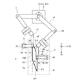
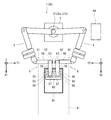
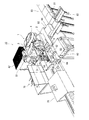
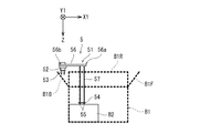
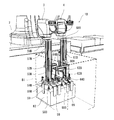
- FIG. 1 is a perspective view showing an example of a boxing apparatus according to Embodiment 1 of the present invention.
- FIG. 2 is a schematic plan view showing a schematic configuration of the boxing device shown in FIG.
- FIG. 3 is a front view of the boxing device shown in FIG.
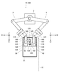
- FIG. 4 is a plan view showing a state during the unfolding operation in the boxing device shown in FIG.
- FIG. 5 is a plan view showing a completed state of the unfolding operation in the boxing device shown in FIG.
- FIG. 6 is a front view showing the positional relationship between the first hand and the second hand and the large box during the unfolding operation.
- FIG. 7 is a plan view showing a state during the housing operation in the boxing device shown in FIG. FIG.
- FIG. 8 is a plan view showing a completed state of the accommodating operation in the boxing device shown in FIG.
- FIG. 9 is a perspective view showing a completed state of the storing operation in the boxing device shown in FIG.
- FIG. 10 is a side view showing the positional relationship between the first hand, the large box, and the middle box during the housing operation.
- FIG. 11 is a perspective view showing an example of a boxing apparatus according to Embodiment 2 of the present invention.
- FIG. 12 is a schematic plan view showing a schematic configuration of the boxing device shown in FIG.
- FIG. 15 is an enlarged perspective view showing a completed state of the storing operation in the boxing device shown in FIG.
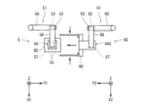
- FIG. 16 is an enlarged plan view showing a first hand and a second hand in a modification of the first embodiment.
- FIG. 1 is a perspective view showing an example of a boxing apparatus according to Embodiment 1 of the present invention.
- FIG. 2 is a schematic plan view showing a schematic configuration of the boxing device shown in FIG.
- FIG. 3 is a front view of the boxing device shown in FIG. 2 and 3 schematically show the configuration of FIG. 1, and the details of the shape and the like are different from the configuration of FIG.
- the boxing device 10 of the present embodiment includes a double-arm robot 1 in which two arms (a first arm 3 and a second arm 4) are provided on a base 2. ing.
- the first arm 3 is provided with a first hand 5 at the tip, and has a plurality of joint axes (six joint axes J1a to J6a in the present embodiment) between the base 2 and the first hand 5. That is, the first arm 3 has a plurality of members (in the present embodiment, the first member 31 to the fifth member 35 from the joint axis J1a side) that connect between two adjacent joint axes.
- the second arm 4 is provided with a second hand 6 at the tip, and at least one joint shaft (six joint shafts J1b to J6b in the present embodiment) is provided between the base 2 and the second hand 6. ). That is, the second arm 4 has a plurality of members (in the present embodiment, the first member 41 to the fifth member 45 from the joint axis J1b side) that connect between two adjacent joint axes.
- the joint axes J1a, J2a, J6a of the first arm 3 are arranged perpendicular to the base 2, and the joint axes J3a, J4a, J5a are arranged horizontally on the base 2 (perpendicular to the joint axes J1a, J2a, J6a). Is done.
- the joint axes J1b, J2b, J6b of the second arm 4 are arranged perpendicular to the base 2, and the joint axes J3b, J4b, J5b are horizontal to the base 2 (perpendicular to the joint axes J1b, J2b, J6b).
- the third member 33 between the joint axis J3a and the joint axis J4a of the first arm 3 and the fourth member 34 between the joint axis J4a and the joint axis J5a have substantially the same length (distance between the joint axes). Have.
- the distal end portion of the first arm 3 (first hand The vertical position can be changed without changing the horizontal position of 5).
- the third member 43 and the fourth member 44 of the second arm 4 are configured similarly to the first arm 3.
- the tips of the arms 3 and 4 are rotated.
- the parts (the first hand 5 and the second hand 6) are configured to move in a plane parallel to the horizontal plane.
- the robot 1 in the present embodiment is configured as a coaxial double-arm robot in which the joint axis J1a and the joint axis J1b are arranged coaxially (configured as a rotation axis C).
- Each of the first arm 3 and the second arm 4 is configured to be rotatable about the rotation axis C independently of each other with respect to the base 2. Since the bases of the two arms 3 and 4 are arranged coaxially, the two arms 3 and 4 are taught in the same way by setting the origin of the robot coordinate system to the coaxial position, and the two arms 3 and 4 are taught in the same manner. Can be controlled with high accuracy without causing a time delay.
- the boxing device 10 has a deployment operation of a later-described large box (first box) B1 and a middle box (second box) B2 in front of the base 2.
- a boxing area A1 for performing the accommodating operation is provided.
- a box transporting device 20 is provided for sealing and transporting the upper end of the box B1 packed with the middle box B2.
- a large box placement area A2 in which a plurality of folded large boxes B1 are stocked is provided on one side of the base 2 in the left-right direction (right side as viewed from the robot 1 facing the packing area A1).
- the large box B1 is a foldable box such as a cardboard box.
- a large box installation device 70 is installed for placing the folded large box B1 placed in the large box placement area A2 on the right end of the packaging area A1. Yes.
- the large box installation device 70 is configured such that a main body 71 is rotatable about a vertical axis, and the main body 71 is provided at a telescopic mechanism 72 that can be expanded and contracted in a direction orthogonal to the vertical axis, and at a distal end of the elastic mechanism 72.
- a suction mechanism 73 is provided.
- a middle box transport device 80 for transporting a plurality of middle boxes B2 is provided on the other side of the base 2 in the left-right direction (left side as viewed from the state facing the packing area A from the robot 1).
- the middle box conveying device 80 includes, for example, a conveyance unit 81 that conveys the middle box B2 such as a roller conveyor or a belt conveyor, and a moving mechanism 82 that moves the middle box B2 to the middle box placement area A4 at the terminal end of the conveyance unit 81. It has.
- An insole board placement area A3 for placing the insole board B3 of the large box B1 is provided on the other side in the left-right direction of the boxing area A1.
- the boxing device 10 includes a controller 9 that controls each of the first arm 3 and the second arm 4.
- the control unit 9 includes a CPU such as a microcontroller and a memory for storing a control program.
- the control unit 9 arbitrarily controls the first hand 5 and the second hand 6 by servo-controlling a servo motor (not shown) for rotationally driving the joint axes J1a to J6a and J1b to J6b of the robot 1. Move along any path to the position.
- the controller 9 may control the operations of the bin installation device 70 and the transport devices 20 and 80.
- the first hand 5 includes a hand base 51, a gripping mechanism 52, and a holding mechanism 54.
- the gripping mechanism 52 has a gripping portion 53 that is provided on the hand base 51 and grips the upper end of a flap portion (outer flap portion) B1R of a large box B1 described later.
- the holding mechanism 54 is provided in the hand base 51 and has a holding portion 55 that holds an inner box B2 described later.
- the second hand 6 includes a hand base 61, a gripping mechanism 62 having a gripping part 63, and a holding mechanism 64 having a holding part 65.
- the configuration of the first hand 5 is as follows.
- the first hand base 51, the first gripping mechanism 52, and the first holding mechanism 54 are referred to, and the configuration of the second hand 6 is referred to as the second hand base 61, the second gripping mechanism 62, and the second holding mechanism 64. There is.
- the gripping mechanisms 52, 62 include a pair of abutting pieces facing each other as the gripping portions 53, 63, and have a clamp structure that sandwiches a plate-shaped gripping object from both sides by opening and closing the pair of abutting pieces. Yes.
- the holding mechanisms 54 and 64 have a suction structure as the holding portions 55 and 65.
- the holding portions 55 and 65 have a suction structure composed of a plurality (six) of suction portions.
- the control unit 9 unfolds the large box B1 and places the middle box B2 in the large box B1 in order to place a plurality of middle boxes B2 in which the items to be packed are accommodated in the large box B1 for packing.
- the operation of the first arm 3, the first hand 5, the second arm 4, and the second hand 6 is controlled so as to perform the operation.
- the first arm 3 and the second arm 4 are arranged such that the gripping portions 53, 63 of the gripping mechanisms 52, 62 are folded at the upper end of the flap portion of the large box B1 (the outer flap portions B1R, With the upper end of B1L gripped, it moves in the horizontal plane so as to unfold the bin B1.
- the first arm 3 and the second arm 4 are arranged in the expanded large box B1 with the holding portions 55 and 65 of the holding mechanisms 54 and 64 holding the inner box B2. It moves so that box B2 may be accommodated.
- the control unit 9 performs control so that the posture of the fifth members 35 and 45 of the arms 3 and 4 does not change in the unfolding operation and the housing operation. That is, the robot 1 performs the unfolding operation and the housing operation by changing the vertical position without changing the horizontal position of the tip of each arm 3, 4 and the tip of each arm 3, 4. This is realized by combining the movement in the plane parallel to the horizontal plane.
- the vertical axis (axis along the Z direction described later) of the orthogonal coordinates is a horizontal plane. It does not rotate around a parallel axis.
- an orthogonal coordinate system (a second direction Z perpendicular to the horizontal plane and a first direction X1, X2 parallel to the horizontal plane) with the base ends (tips of the arms 3 and 4) of the respective hands 5 and 6 as the origin is set.
- the configuration of each hand 5, 6 will be described using the third direction Y1, Y2).
- the Cartesian coordinate system of each of the hands 5 and 6 mirrors each other when the positions of the tips of the arms 3 and 4 include a common rotation axis C and are positioned symmetrically with respect to a plane perpendicular to the horizontal plane. It is set to be symmetrical.
- the first hand 5 and the second hand 6 are gripping portions 53, 63 of the gripping mechanisms 52, 62.
- the holding portions 55 and 65 of the holding mechanisms 54 and 64 are configured to be located at a position separated in a plan view and a position separated in the vertical direction.
- the hand base portions 51 and 61 include first extension portions 56 and 66 extending in a first direction (horizontal direction: X1 and X2 directions), and first end portions 56a of the first extension portions 56 and 66, 66a, and includes second extending portions 57 and 67 extending in a second direction (downward: Z direction) orthogonal to the first directions X1 and X2.
- the first extending portions 56 and 66 are made of a flat plate member, and the second extending portions 57 and 67 are made of a plurality of (four) rod-like members.
- the gripping mechanisms 52 and 62 are attached so that the gripping portions 53 and 63 are directed in the second direction Z at the second ends 56b and 66b of the first extending portions 56 and 66.
- the holding mechanisms 54 and 64 are attached so that the holding portions 55 and 65 face the second direction Z at the distal ends of the second extending portions 57 and 67.
- the mounting positions of the gripping portions 53 and 63 of the gripping mechanisms 52 and 62 are the same as the mounting positions of the holding portions 55 and 65 of the holding mechanisms 54 and 64 by the length of the first extending portion 56. It is spaced apart in the horizontal direction (first direction X1, X2). Further, the mounting positions of the gripping portions 53 and 63 of the gripping mechanisms 52 and 62 are vertically moved (first direction) with respect to the mounting positions of the holding portions 55 and 65 of the holding mechanisms 54 and 64 by the length of the second extending portion 57. In two directions Z).
- the hand bases 51 and 61 are third extensions extending from the base ends of the hand bases 51 and 61 in a third direction (horizontal direction: Y1, Y2 direction) orthogonal to the first direction X1, X2 and the second direction Z.
- Protruding portions 58 and 68 are provided.
- the 3rd extension parts 58 and 68 are constituted by a flat plate member.
- the second end portions 56 b and 66 b of the first extension portions 56 and 66 are attached to the distal end portions of the third extension portions 58 and 68.
- the first end portions 56 a and 66 a of the first extension portions 56 and 66 are attached to the base end portions of the second extension portions 57 and 67.
- the first end portions 56a and 56b of the first extension portions 56 and 66 are the front end portions of the first extension portions 56 and 66, and the first extension portions 56 and 66 have first ends.
- the two end portions 56b and 66b are base end portions of the first extending portions 56 and 66.
- the grip portions 53 and 63 are configured such that a pair of contact pieces open and close in the first directions X1 and X2.
- the first hand 5 and the second hand 6 in the present embodiment are configured to be mirror-symmetric with each other in a state where the third directions Y1 and Y2 are aligned in the same direction (the state shown in FIG. 2). .
- FIG. 4 is a plan view showing a state during the unfolding operation in the boxing device shown in FIG. 2
- FIG. 5 is a plan view showing a completed state of the unfolding operation in the boxing device shown in FIG. FIG. 1 also shows the completion state of the unfolding operation.
- the bin installation device 70 places the folded bin B1 at the initial position P0 at the right end of the boxing region A1.
- the folded large bin B1 is in contact with the inner side surface of the outer flap portion B1R and the inner side surface of the inner flap portion B1B, and the outer flap portion B1L and the inner flap portion B1F are in contact with each other.
- a part of B1L and a part of the outer flap part B1R are in contact with each other.
- the control unit 9 includes the first arm so that the grip 53 of the first gripping mechanism 52 grips the upper end of the right outer flap B1R when viewed from the base 2 side of the large box B1 placed at the initial position P0. 3 is controlled.
- the gripping part 53 grips the upper end of the outer flap part B1R on the side close to the base 2 (the side close to the inner flap part B1B).
- the control unit 9 holds the upper end of the left outer flap B1L as viewed from the base 2 side of the large box B1 on which the gripping part 63 of the second gripping mechanism 62 is placed at the initial position P0.
- the second arm 4 is controlled.
- the front-rear direction position for gripping the upper end of B1L is the same position. However, since the bin B1 placed at the initial position P0 is folded, the position coordinates of the gripping portion 53 of the first gripping mechanism 52 and the position coordinates of the gripping portion 63 of the second gripping mechanism 62 are The position is shifted in the third direction Y1, Y2 by the length of the flap portion B1B.
- the control unit 9 moves the first arm 3 and / or the second arm 4 in the horizontal plane while the gripping portions 53 and 63 of the gripping mechanisms 52 and 62 grip the outer flap portions B1R and B1L. By doing so, the control to expand the large box B1 is performed.
- the first arm 3 does not move, and the second arm 4 moves in an arc shape in a horizontal plane, so that the inner flap portion B1B is centered on the connection end with the outer flap portion B1R. It rotates until the angle between B1B and the outer flap B1R is 90 °.
- the joint box J1b, J2b, J6b of the second arm 4 is rotated in a state where the gripping portions 53, 63 grip the outer flap portions B1R, B1L, whereby the large box B1 is deployed.
- the first extending portions 56 and 66 are positioned on a straight line, and the third extending portions 58 and 68 are positioned parallel to each other.
- the control unit 9 After the unfolding operation by the second arm 4, the control unit 9 holds the hands 5, 6 in the large box B 1 while gripping the outer flap portions B 1 R, B 1 L by the grip portions 53, 63 of the grip mechanisms 52, 62. By controlling the arms 3 and 4 so as to move outward in the left-right direction (the direction in which the distance between the gripping portions 53 and 63 increases), the outer flap portions B1R and B1L of the large box B1 are maintained in an open state. An urging assist operation may be performed. Further, after the unfolding operation by the second arm 4, the control unit 9 moves outward in the front-rear direction of the large box B1 with the side surfaces of the holding mechanisms 54 and 64 in contact with the inner side surfaces of the inner flap portions B1B and B1F. By controlling the arms 3 and 4 so as to perform the biasing assisting operation, the inner flap portions B1B and B1F of the large box B1 may be kept open.
- FIG. 6 is a front view showing the positional relationship between the first hand and the second hand and the large box during the unfolding operation.
- illustration of the inner flaps B1B and B1F of the large box B1 is omitted.
- 6 is a view as seen from the arrow VI in FIG.
- the positional relationship between each hand 5, 6 and the large box B1 when viewed from the arrow VI during the unfolding operation does not change except for the distance between the hands 5, 6. That is, the positional relationship shown in FIG. 6 is also established in FIG.
- the first hand 5 and the second hand 6 have the holding mechanism 54 when the gripping portions 53, 63 of the gripping mechanisms 52, 62 grip the upper ends of the outer flap portions B1R, B1L of the large box B1. 64 are located outside the large box B1. This reliably prevents the holding mechanisms 54 and 64 from interfering with the large box B1 during the unfolding operation of the large box B1.
- the robot 1 After the unfolding operation of the large box B1, the robot 1 performs an operation of accommodating the insole board B3 placed in the insole board placing area A3 in the large box B1.
- the control part 9 controls the 1st arm 3 so that the 1st holding mechanism 54 of the 1st hand 5 may be located on the insole board B3 mounted in the insole board mounting area
- the first hand 5 holds the insole board B3 by the holding part 55 of the first holding mechanism 54 adsorbing the upper surface of the insole board B3.
- the controller 9 controls the first arm 3 so that the insole board B3 is accommodated in the large box B1.
- control unit 9 moves the second arm 6 so that the second hand 6 moves onto the middle box placement region A4 of the middle box transport device 80 for the operation of housing the middle box B2 performed as the next step. 4 is controlled. Thereby, it can prevent that the 2nd arm 4 interferes with the accommodation operation
- FIG. 7 is a plan view showing a state during the accommodating operation in the boxing device shown in FIG. 2
- FIG. 8 is a plan view showing a completed state of the accommodating operation in the boxing device shown in FIG.
- FIG. 9 is a perspective view showing a completed state of the storing operation in the boxing device shown in FIG. 8 and 9, the completion state of the accommodating operation means a state where the first middle box B2 can be accommodated in the large box B1.
- the control unit 9 controls the first arm 3 so that the first hand 5 also moves onto the middle box placement area A4 of the middle box transport device 80. More specifically, the control unit 9 moves the first arm 3 and the second arm 4 so that the two holding mechanisms 54 and 64 are adjacently disposed along the first direction X1 and X2 on the inner box placement region A4. Control. As described above, after the holding mechanisms 54 and 64 are arranged on the middle box B2 placed on the middle box placement area A4, the two holding portions 55 and 65 absorb the upper surface of the middle box B2 so that the middle. Box B2 is held.
- the holding mechanisms 54 and 64 of the respective hands 5 and 6 are arranged in the first direction X1 and X2 with respect to each other in order to hold one middle box B2. Configured to hold. At this time, the 1st extension parts 56 and 66 are located mutually parallel, and the 3rd extension parts 58 and 68 are located on a straight line.
- control unit 9 After holding the inner box B2, the control unit 9 places the inner box B2 held by the holding units 55 and 65 in the developed large box B1 by cooperatively controlling the two arms 3 and 4. That is, the control unit 9 moves the held inner box B2 by cooperatively controlling the two arms 3 and 4 while maintaining the positional relationship between the two holding mechanisms 54 and 64.
- the middle box B2 held by the holding portions 55 and 65 is lifted by performing an operation of changing the vertical position without changing the horizontal position of the tip portions of the two arms 3 and 4. Further, as shown in FIG. 7, the control unit 9 performs the operation of moving the tip portions (the respective hands 5 and 6) of the arms 3 and 4 in a plane parallel to the horizontal plane, thereby holding the holding units 55 and 65.
- the middle box B2 held by is moved to a predetermined placement position on the large box B1. Thereafter, by performing an operation of changing the vertical position without changing the horizontal position of the tip of the two arms 3 and 4, the middle box B2 held by the holding parts 55 and 65 is mounted on the large box B1. Place it on the mounting position.
- FIG. 10 is a side view showing the positional relationship between the first hand, the large box, and the middle box during the housing operation.
- FIG. 10 is a view of the first hand 5 in FIG. 8 viewed from the third direction Y1.
- the large box B1 is indicated by a broken line.
- the first hand 5 and the middle box B2 in the large box B1 are shown through the large box B1.
- the second hand 6 has the same positional relationship as that in FIG. 10, but the first hand 5 is illustrated in the following description.
- the first hand 5 is placed on the bottom surface of the large box B1 with the middle box B2 held by the holding part 55 in contact with the side surface connected to the inner flap B1B of the large box B1.
- the gripping portion 53 of the gripping mechanism 52 is positioned outside the side surface of the large box B1 (front side when viewed from the state facing the boxing area A1 from the robot 1) and above the lower end of the inner flap portion B1B.
- the gripping mechanisms 52 and 62 are located between the rotation axis C of the robot 1 and the holding mechanisms 54 and 64 in plan view.
- the length of the second extending portion 57 in the second direction (Z direction) is the distance between the distal end portion of the holding mechanism 54 (the suction surface of the holding portion 55) and the distal end portion of the gripping mechanism 52 (the lower end of the gripping portion 53).
- the distance in the vertical direction (second direction Z) between the length from the bottom surface of the large box B1 to the lower end of the inner flap B1B (the height of the large box B1 when the flap is closed) It is set to be longer than the length minus the height.
- each arm 3, 4 is set to a distance substantially equal to the length from the distal end portion to the distal end portions (adsorption surfaces) of the holding portions 55 ⁇ / b> B and 65 ⁇ / b> B.
- the gripping mechanisms 52 and 62 are located between the rotation axis C of the robot 1 and the holding mechanisms 54 and 64 in plan view.
- the large box B1 is formed in a size that can accommodate a plurality of middle boxes B2.
- two middle boxes B2 can be placed in the front-rear direction as seen from the state in which the robot 1 faces the packaging area A1, and two middle boxes B2 can be placed in the height direction. is there. That is, four middle boxes B2 can be placed in the large box B1.
- the control unit 9 performs the control for the accommodating operation of the middle box B2 four times while changing the mounting position at each time for one large box B1.
- the control unit 9 again performs the hand 5,6. Is moved to the middle box placement area A4 of the middle box transport device 80, and the second middle box B2 placed in the middle box placement area A4 is held using the holding portions 55 and 65.
- the arms 3 and 4 are controlled.
- the control unit 9 controls the arms 3 and 4 so that the inner box B2 held by the holding units 55 and 65 is placed at a predetermined placement position on the large box B1.
- the mounting position of the second inner box B2 is, for example, a mounting position on the lower side and the back side.
- the third middle box B2 is placed at the placement position on the front side of the upper stage, and the fourth middle box B2 is placed at the placement position on the back side of the upper stage.
- the control unit 9 may perform control to place the insole board B3 on the two lower middle boxes B2 again using the first arm 3 after the lower two middle boxes B2 are placed. Good.
- the large boxes B1 are conveyed to the outside of the boxing area A1 by the large box conveying device 20, and the flap portions B1B, B1F, B1R, B1L is closed and the packing operation is completed.
- the control unit 9 holds the outer flaps B1R and B1L by the grasping parts 53 and 63 of the grasping mechanisms 52 and 62 while holding the hands 5, 6
- assistance for closing the outer flap portions B1R and B1L of the large box B1 may be performed.
- a gripping mechanism 52 having gripping portions 53 and 63 that grip the upper ends of the flap portions (outer flap portions) B1R and B1L of the large box B1 in order to unfold the large box B1.
- 62 and holding mechanisms 54, 64 having holding portions 55, 65 for holding the inner box B2 are provided on the respective hands 5, 6.
- the gripping portions 53 and 63 and the holding portions 55 and 65 are configured to be located at a position separated in a plan view and a position separated in the vertical direction.
- the holding portions 55 and 65 are located at positions where they do not overlap with the grip portions 53 and 63 in plan view, so that the flap portion (outside of the bin B1)
- the holding mechanisms 54 and 64 are prevented from interfering with the bin B1 during the unfolding operation of the bin B1.
- the holding portions 55 and 65 and the gripping portions 53 and 63 are separated in the vertical direction, the holding portions 55 and 65 hold the inner box B2 in the large box B1 (that is, the lower end of the flap portion B1B).
- the gripping mechanisms 52 and 62 are prevented from interfering with the large box B1 in the accommodating operation of the middle box B2. Therefore, the operation of expanding the large box B1 and placing a plurality of middle boxes B2 therein can be efficiently performed by one boxing device 10 (robot 1).
- the “gripping portion” (53, 63) means the bin B1 for grasping the flap portions B1R, B1L of the bin B1 by the grasping mechanisms 52, 62. It means the part that touches.
- the “holding portion” (55, 65) means a portion in contact with the inner box B2 in order to hold the inner box B2 by the holding mechanisms 54, 64. means.
- the gripping portion of the gripping mechanism and the holding portion of the holding mechanism are located at positions separated from each other in plan view” means that the gripping operation is performed in the expansion operation of the large box B1.
- portions of the gripping mechanisms 52 and 62 other than the gripping portions 53 and 63 and portions of the holding mechanisms 54 and 64 other than the holding portions 55 and 65 may overlap in plan view.
- portions of the gripping mechanisms 52 and 62 other than the gripping portions 53 and 63 and portions of the holding mechanisms 54 and 64 other than the holding portions 55 and 65 are movable for performing a gripping operation in the gripping portions 53 and 63, for example.
- the first extending portions 56 and 66 are provided with the gripping portions 53 and 63, and the second extending portions 57 and 67 are provided with the holding portions 55 and 65, thereby simplifying the configuration. And without making it the structure which moves the holding parts 53 and 63 or the holding parts 55 and 65 for interference avoidance (that is, without changing the relative position of the holding parts 53 and 63 and the holding parts 55 and 65) During one operation of the unfolding operation of B1 and the accommodating operation of the inner box B2, it is possible to prevent a mechanism that is not used for the operation from interfering with the operation.
- the coaxial two-arm robot 1 is configured to perform the above-described deployment operation and accommodation operation.
- the two arms 3 and 4 perform the cooperative operation, the expansion operation of the large box B1 and the housing operation of the middle box B2 can be performed more efficiently.
- the two arms 3 and 4 are coaxially arranged by the rotation axis C, space efficiency and controllability can be improved.
- FIG. 11 is a perspective view showing an example of a boxing device according to Embodiment 2 of the present invention.
- FIG. 12 is a schematic plan view showing a schematic configuration of the boxing device shown in FIG.
- FIG. 13 is a front view of the boxing device shown in FIG. 12 and 13 schematically show the configuration of FIG. 11, and the details of the shape and the like differ from the configuration of FIG.
- the same components as those in the first embodiment are denoted by the same reference numerals, and description thereof is omitted.
- the difference between the boxing device 10B in the second embodiment and the boxing device 10 in the first embodiment is that the configuration of the hand bases 51B and 61B in the hands 5B and 6B is different from the hand bases 51 and 61 in the first embodiment. That is.
- the hand base portions 51B and 61B include first extending portions 56B and 66B, second extending portions 57B and 67B, and third extending portions 58B and 68B.
- first extending portions 56B and 66B extend in the first direction X1 and X2.
- the second extending portions 57B and 67B are attached to the first ends 56a and 66a of the first extending portions 56B and 66B and extend in the second direction Z.
- the third extending portions 58B and 68B extend in the third direction Y1 and Y2.
- the base end portions of the second extending portions 57B and 67B are attached to the distal end portions of the third extending portions 58B and 68B, and the first extending portions 56B and The first end portions 56a and 66a of 66B are attached to an intermediate portion that is a predetermined distance above the tips of the second extending portions 57B and 67B. That is, in the present embodiment, the first end portions 56a and 56b of the first extension portions 56B and 66B are the base end portions of the first extension portions 56B and 66B, and the first extension portions 56B and 66B. The second end portions 56b and 66b are tip portions of the first extending portions 56B and 66B.
- each of the second extending portions 57B and 67B is composed of one prismatic member.
- the gripping mechanisms 52B and 62B of the respective hands 5 and 6 are arranged so that the gripping portions 53B and 63B face the second direction Z at the second end portions 56b and 66b of the corresponding first extending portions 56B and 66B, respectively. It is attached.
- the holding mechanisms 54B and 64B of the hands 5 and 6 are attached so that the holding portions 55B and 65B face the second direction Z at the tip ends of the corresponding second extending portions 57B and 67B, respectively.
- the second extending portions 57B and 67B are located on the first surfaces 57a and 67a on the distal end side of the third extending portions 58B and 68B and on the opposite side of the first surfaces 57a and 67a. It has the 2nd surface 57b, 67b.
- the length of the third extension 58B of the first hand 5B (the length from the tip of the first arm 3B to the mounting position of the second extension 57B) and the third extension 68B of the second hand 6B.
- the length (the length from the tip of the second arm 4B to the mounting position of the second extending portion 67B) is the same.
- the first end portion 56a of the first extension portion 56B of the first hand 5B is attached to the second surface 57b of the second extension portion 57B.
- the first end 66a of the first extension 66B of the second hand 6B is attached to the first surface 67a of the second extension 67B.
- the attachment position of the first extension portion 56B of the first hand 5 to which the first gripping mechanism 52B is attached to the second extension portion 57B and the second gripping mechanism 62B are attached.
- the attachment position of the first extension portion 66B of the two hands 6 to the second extension portion 67B is staggered with respect to the third directions Y1 and Y2 with the third directions Y1 and Y2 arranged in the same direction. It has become. Therefore, unlike the first embodiment, the first hand 5B and the second hand 6B in the present embodiment are mirror images of each other even when the third directions Y1 and Y2 are aligned in the same direction (the state shown in FIG. 12). It is not a symmetrical relationship.
- the robot 1B in the present embodiment also performs the unfolding operation of the large box B1 and the accommodating operation of the middle box B2 as in the first embodiment. 11 and 12 show a completed state of the unfolding operation of the large box B1.
- the first hand 5B and the second hand 6B in the present embodiment are not in a mirror-symmetric relationship with each other. Therefore, in the control unit 9, the first gripping mechanism 52B of the first hand 5B grips the outer flap portion B1R of the large box B1, and the second gripping mechanism 62B of the second hand 6B is the outer flap portion B1L of the large box B1.
- the position of the tip of the first arm 3 and the position of the tip of the second arm 4 are Control is performed so as to move to positions shifted from each other in the directions Y1 and Y2.
- the first extending portions 56B and 66B are positioned on a straight line
- the third extending portions 58B and 68B are positioned parallel to each other.
- the robot 1B of the present embodiment is slightly different from the robot 1 of the first embodiment in the unfolding operation of the bin B1, but also in the present embodiment, the first hand 5B and the second hand 6B is common in that when the gripping portions 53B and 63B of the gripping mechanisms 52B and 62B grip the upper ends of the outer flap portions B1R and B1L of the large box B1, the holding mechanisms 54B and 64B are positioned outside the large box B1. doing.
- the holding mechanisms 54B and 64B interfere with the large box B1 in the unfolding operation of the large box B1.
- the control unit 9 controls the operations of the arms 3B and 4B in the same manner as in the first embodiment in the housing operation of the inner box B2. That is, the holding mechanisms 54B and 64B of the respective hands 5B and 6B are arranged in the first direction X1 and X2 with respect to each other in order to hold one middle box B2, respectively. Configured to hold. After holding the middle box B2, the control unit 9 controls the two arms 3 and 4 to place the middle box B2 held by the holding parts 55B and 65B in the developed large box B1.
- FIG. 14 is a plan view showing a completed state of the accommodating operation in the boxing device shown in FIG.
- FIG. 15 is an enlarged perspective view showing a completed state of the accommodating operation in the boxing device shown in FIG.
- the hands 5B and 6B are arranged along the third direction Y1 and Y2 with the holding mechanisms 54B and 64B holding the one inner box B2. It is configured to be.
- the positions of the second extending portions 57B and 67B in the third directions Y1 and Y2 are the same position.
- the first extending portions 56B and 66B are positioned in parallel to each other, and the third extending portions 58B and 68B are positioned in parallel to each other.
- the holding mechanisms 54B and 64B are arranged in the horizontal direction (first direction X1, X2 and third direction Y1, Y2) when holding the inner box B2.
- guide members 59 and 69 for regulating the relative positions of the inner box B2 and the holding portions 55B and 65B.
- the guide members 59 and 69 are not shown.
- the guide members 59 and 69 include a horizontal piece projecting in the first direction X1, X2 and / or the third direction Y1, Y2 direction from the base of the holding mechanism 54B, 64B, and the second direction Z (downward from the tip of the horizontal piece. ) And a vertical piece extending.
- the inner box B2 can be held at an appropriate position by the holding portions 55B and 65B of the holding mechanisms 54B and 64B.
- such guide members 59 and 69 may be provided.
- each of the two hands 5 and 6 may hold one middle box B2 so that two middle boxes B2 are accommodated in the large box B1 in one accommodation operation.
- FIG. 16 is an enlarged plan view showing a first hand and a second hand in a modification of the first embodiment.
- the first hand 5 has the same configuration as that of the first embodiment.
- the second hand 6C includes a gripping mechanism 62 having the same gripping part (first gripping part) 63 as in the first embodiment and holding parts 55, 65, 55B having the suction structure of the first or second embodiment.
- a holding mechanism 64C having a second grip 90 that grips the inner box B2 from the side (first direction X2) is provided.
- control unit 9 controls the first arm 3 and the second arm 4 in a coordinated manner and maintains the holding state of the inner box B2 by the holding unit 55 and the second gripping unit 90, while the middle box B2 is moved to the large box B1. The operation which accommodates in is performed.
- the present invention can be applied to a boxing device having three or more arms or a boxing device having only one arm.
- the boxing device 10 changes the vertical position without changing the horizontal position of the distal ends of the two arms 3 and 4, and the distal ends of the arms 3 and 4.
- an arm that can control the position of the hand three-dimensionally such as a 6-axis articulated robot
- the present invention can also be applied to a case where the boxing device is configured using a robot having one or more of the above.
- the unfolding operation of the large box B1 is performed, for example, in a state where the large box transport device 70 holds the side surface of the large box B1 to which the outer flap portion B1R is connected.
- one hand connected to it is realizable by performing operation similar to the 2nd arms 5 and 5B and the 2nd hands 6 and 6B in the above-mentioned embodiment.
- the present invention is useful for efficiently performing the work of developing a large box and placing a plurality of middle boxes therein with a single device.
Landscapes
- Engineering & Computer Science (AREA)
- Mechanical Engineering (AREA)
- Robotics (AREA)
- Manipulator (AREA)
- Container Filling Or Packaging Operations (AREA)
- Supplying Of Containers To The Packaging Station (AREA)
- Auxiliary Devices For And Details Of Packaging Control (AREA)
- Seal Device For Vehicle (AREA)
Abstract
第1アームと、第1ハンドと、制御部と、を備え、第1ハンドは、ハンド基部と、ハンド基部に設けられ、大箱のフラップ部上端を把持する把持部を有する把持機構と、ハンド基部に設けられ、中箱を保持する保持部を有する保持機構と、を備え、制御部は、把持機構の把持部が、折り畳まれた状態の大箱のフラップ部上端を把持した状態で、大箱を展開するように水平面内を移動する展開動作と、保持機構の保持部が、中箱を保持した状態で、展開された大箱内に中箱を収容させる収容動作と、を行うように、第1アームおよび第1ハンドの動作を制御し、第1ハンドは、把持機構の把持部と保持機構の保持部とが、平面視において離間した位置、かつ、垂直方向に離間した位置に位置するように構成されている。
Description
本発明は、梱包用の大箱内に被梱包物が収容された複数の中箱を載置するための箱詰装置に関する。
製品の製造ライン等には、所定数量の製品(被梱包物)を中箱に収容し、複数の中箱をさらに大きい大箱に載置して梱包する工程が存在する場合がある。既存の製造ライン等においては、このような工程は、作業員が、折り畳まれた状態の大箱を展開して箱組みする作業を行った後、当該展開した大箱内に載置する作業を行っていることが多い。
ここで、下記特許文献1には、折り畳まれた箱(大箱)を展開して箱組みする作業を自動化した装置が提案されている。
また、下記特許文献2には、複数の物品を大箱に載置させるためのロボットが提案されている。
しかしながら、従来の構成では、大箱の展開後、物品をその中に載置することを1つの装置で行うことはできなかった。そのため、1つの装置でこれらを行うための課題についても知られていなかった。
本発明は、上記課題を解決するものであり、大箱を展開し、その中に複数の中箱を載置する作業を1つの装置で効率よく行うことができる箱詰装置を提供することを目的とする。
本発明の一態様に係る箱詰装置は、梱包用の大箱内に被梱包物が収容された複数の中箱を載置するための箱詰装置であって、複数の関節軸を有する第1アームと、前記第1アームの先端部に設けられる第1ハンドと、前記第1アームおよび前記第1ハンドの動作を制御する制御部と、を備え、前記第1ハンドは、ハンド基部と、前記ハンド基部に設けられ、前記大箱のフラップ部上端を把持する把持部を有する把持機構と、前記ハンド基部に設けられ、前記中箱を保持する保持部を有する保持機構と、を備え、前記制御部は、前記把持機構の把持部が、折り畳まれた状態の前記大箱のフラップ部上端を把持した状態で、前記大箱を展開するように水平面内を移動する展開動作と、前記保持機構の保持部が、前記中箱を保持した状態で、展開された前記大箱内に前記中箱を収容させる収容動作と、を行うように、前記第1アームおよび前記第1ハンドの動作を制御し、前記第1ハンドは、前記把持機構の把持部と前記保持機構の保持部とが、平面視において離間した位置、かつ、垂直方向に離間した位置に位置するように構成されている。
上記構成によれば、大箱を展開するために大箱のフラップ部上端を把持する把持部を有する把持機構と、中箱を保持する保持部を有する保持機構とが、1つのハンドに設けられる。しかも、把持部と保持部とは、平面視において離間した位置、かつ、垂直方向に離間した位置に位置するように構成される。このような構成を有することにより、大箱を展開するために大箱のフラップ部上端を把持した際に、保持部が把持部に対して平面視において重ならない位置に位置するため、大箱の展開動作において保持機構が大箱に干渉することが防止される。また、保持部が中箱を保持した状態で大箱内(すなわち、フラップ部基部より下方)に移動した際に、保持部と把持部とが上下方向に離間しているため、中箱の収容動作において把持機構が大箱に干渉することが防止される。したがって、大箱を展開し、その中に複数の中箱を載置する作業を1つの装置で効率よく行うことができる。
前記ハンド基部は、第1方向に延びる第1延出部と、前記第1延出部の第1端部に取り付けられ、前記第1方向に直交する第2方向に延びる第2延出部とを備え、前記把持機構は、前記第1延出部の第2端部において前記把持部が前記第2方向を向くように取り付けられ、前記保持機構は、前記第2延出部の先端部において前記保持部が前記第2方向を向くように取り付けられてもよい。
上記構成のように、第1延出部に把持部が設けられ、第2延出部に保持部が設けられることにより、簡単な構成かつ把持部または保持部を干渉回避のために可動させる構成とすることなく(把持部および保持部の相対位置を変更させることなく)大箱の展開動作および中箱の収容動作のうちの一方の動作中に、当該動作に使用されない機構がその動作に干渉することを防止することができる。
前記第1ハンドは、前記把持機構の把持部が前記大箱のフラップ部上端を把持した際、前記保持機構が前記大箱より外側に位置してもよい。これにより、大箱の展開動作において保持機構が大箱に干渉することがより確実に防止される。
前記箱詰装置は、複数の関節軸を有する第2アームと、前記第2アームの先端部に設けられる第2ハンドと、を備え、前記第2ハンドは、ハンド基部と、前記ハンド基部に設けられ、前記大箱のフラップ部上端を把持する把持部を有する把持機構と、前記ハンド基部に設けられ、前記中箱を保持する保持部を有する保持機構と、を備えてもよい。上記構成によれば、2つのアームが協調動作することにより、より効率的に大箱の展開動作および中箱の収容動作を行うことができる。
前記第1のアームおよび前記第2のアームのそれぞれは、基台に垂直な軸に同軸に配置されかつ前記基台に対して独立して前記軸回りに回動可能に構成されてもよい。上記構成によれば、2つのアームが同軸配置されるため、スペース効率および制御性を高めることができる。
前記第1ハンドおよび前記第2ハンドの前記ハンド基部は、それぞれ、第1方向に延びる第1延出部と、前記第1延出部の第1端部に取り付けられ、前記第1方向に直交する第2方向に延びる第2延出部とを備え、前記第1ハンドおよび前記第2ハンドの前記把持機構は、それぞれ、対応する前記第1延出部の第2端部において前記把持部が前記第2方向を向くように取り付けられ、前記第1ハンドおよび前記第2ハンドの前記保持機構は、それぞれ、対応する前記第2延出部の先端部において前記保持部が前記第2方向を向くように取り付けられ、前記第1ハンドおよび前記第2ハンドの前記保持機構は、一の中箱を保持するために、互いに前記第1方向に沿って配列された状態で、それぞれ、前記一の中箱を保持するよう構成され、前記第1ハンドおよび前記第2ハンドの前記把持機構は、前記保持機構が前記一の中箱を保持した状態で、前記第1方向および前記第2方向に直交する第3方向に沿って配列されるよう構成されてもよい。
上記構成によれば、2つの保持機構により一の中箱を保持した場合に、2つの保持機構の配列方向に直交する方向に2つの把持機構が配列される。これにより、保持機構によって中箱を保持した際に、各把持機構を2つ保持機構の間に配置させることができる。したがって、中箱の保持時に、平面視において中箱の上面より外側に把持機構がはみ出る領域を減らすことができる。これにより、大箱内への中箱の収容動作において把持機構が外箱等に干渉することを防止することができる。
本発明の上記目的、他の目的、特徴、および利点は、添付図面参照の下、以下の好適な実施態様の詳細な説明から明らかにされる。
本発明は以上に説明したように構成され、大箱を展開し、その中に複数の中箱を載置する作業を1つの装置で効率よく行うことができるという効果を奏する。
以下、本発明の実施の形態を、図面を参照しながら説明する。なお、以下では全ての図を通じて同一または相当する要素には同一の参照符号を付して、その重複する説明を省略する。
[実施の形態1]
図1は本発明の実施の形態1に係る箱詰装置の例を示す斜視図である。また、図2は図1に示す箱詰装置の概略構成を示す模式的な平面図である。また、図3は図2に示す箱詰装置の正面図である。図2および図3においては、図1の構成を模式的に示すものであり、図1の構成とは形状の詳細等が異なっている。
図1は本発明の実施の形態1に係る箱詰装置の例を示す斜視図である。また、図2は図1に示す箱詰装置の概略構成を示す模式的な平面図である。また、図3は図2に示す箱詰装置の正面図である。図2および図3においては、図1の構成を模式的に示すものであり、図1の構成とは形状の詳細等が異なっている。
図1から図3に示すように、本実施の形態の箱詰装置10は、基台2に2つのアーム(第1アーム3および第2アーム4)が設けられた双腕のロボット1を備えている。第1アーム3は、先端部に第1ハンド5が設けられ、基台2と第1ハンド5との間に複数の関節軸(本実施の形態では6つの関節軸J1a~J6a)を有する。すなわち、第1アーム3は、隣接する2つの関節軸間同士を繋ぐ複数のメンバ(本実施の形態では関節軸J1a側から第1メンバ31~第5メンバ35)を有する。
同様に、第2アーム4は、先端部に第2ハンド6が設けられ、基台2と第2ハンド6との間に少なくとも1つの関節軸(本実施の形態では6つの関節軸J1b~J6b)を有する。すなわち、第2アーム4は、隣接する2つの関節軸間同士を繋ぐ複数のメンバ(本実施の形態では関節軸J1b側から第1メンバ41~第5メンバ45)を有する。
第1アーム3の関節軸J1a,J2a,J6aは、基台2に垂直に配置され、関節軸J3a,J4a,J5aは、基台2に水平(関節軸J1a,J2a,J6aに垂直)に配置される。同様に、第2アーム4の関節軸J1b,J2b,J6bは、基台2に垂直に配置され、関節軸J3b,J4b,J5bは、基台2に水平(関節軸J1b,J2b,J6bに垂直)に配置される。第1アーム3の関節軸J3aと関節軸J4aとの間の第3メンバ33、および、関節軸J4aと関節軸J5aとの間の第4メンバ34がほぼ同じ長さ(関節軸間距離)を有している。
これにより、平面視において関節軸J3aおよび関節軸J5aが同軸配置された状態で第3メンバ33と第4メンバ34とのなす角を変更することにより、第1アーム3の先端部(第1ハンド5)の水平方向位置を変化させることなく垂直方向位置を変化させることができる。第2アーム4の第3メンバ43および第4メンバ44についても第1アーム3と同様に構成されている。
また、水平方向の関節軸J3a~J5a,J3b~J5bが回動しない状態で垂直方向の関節軸J1a,J2a,J6a,J1b,J2b,J6bが回動することにより、各アーム3,4の先端部(第1ハンド5および第2ハンド6)が水平面に平行な面内を移動するように構成されている。
本実施の形態におけるロボット1は、関節軸J1aと関節軸J1bとが同軸配置された(回動軸Cとして構成された)同軸双腕ロボットとして構成されている。第1アーム3および第2アーム4のそれぞれは、基台2に対して互いに独立して回動軸C回りに回動可能に構成される。2つのアーム3,4の基部が同軸に配置されるため、ロボット座標系の原点を当該同軸位置に設定することにより、2つのアーム3,4を同じように教示し、2つのアーム3,4を、時間遅延を生じさせずに高精度に制御することができる。
図1に示すように、本実施の形態の箱詰装置10は、基台2の前方に、後述する大箱(第1の箱)B1の展開動作および中箱(第2の箱)B2の収容動作を行うための箱詰領域A1が設けられる。箱詰領域A1の前方には、中箱B2が箱詰された大箱B1の上端部をシールして搬送するための大箱搬送装置20が設けられる。
基台2の左右方向一方側(ロボット1から箱詰領域A1を向いた状態から見て右側)には、複数の折り畳まれた大箱B1がストックされる大箱載置領域A2が設けられる。大箱B1は、段ボール箱等の折り畳み可能な箱体である。箱詰領域A1の左右方向一方側には、大箱載置領域A2に載置された折り畳まれた大箱B1を箱詰領域A1の右端部に載置する大箱設置装置70が設置されている。大箱設置装置70は、本体部71が垂直軸回り回転可能に構成され、当該本体部71は、垂直軸に直交する方向に伸縮可能な伸縮機構72および伸縮機構72の先端部に設けられた吸着機構73を備えている。
また、基台2の左右方向他方側(ロボット1から箱詰領域Aを向いた状態から見て左側)には、複数の中箱B2を搬送する中箱搬送装置80が設けられている。中箱搬送装置80は、例えばローラコンベアまたはベルトコンベア等の中箱B2を搬送する搬送部81と、搬送部81の終端部において中箱B2を中箱載置領域A4に移動させる移動機構82とを備えている。箱詰領域A1の左右方向他方側には、大箱B1の中敷板B3を載置する中敷板載置領域A3が設けられている。
箱詰装置10は、第1アーム3および第2アーム4のそれぞれを制御する制御部(コントローラ)9を備えている。制御部9は、マイクロコントローラ等のCPUおよび制御プログラムを記憶するメモリ等を備えている。制御部9は、ロボット1の各関節軸J1a~J6a,J1b~J6bを回動駆動するためのサーボモータ(図示せず)をサーボ制御することにより、第1ハンド5および第2ハンド6を任意の位置に任意の経路に沿って移動させる。制御部9は、大箱設置装置70および各搬送装置20,80の動作を制御してもよい。
第1ハンド5は、ハンド基部51、把持機構52および保持機構54を備えている。把持機構52は、ハンド基部51に設けられ、後述する大箱B1のフラップ部(外フラップ部)B1Rの上端を把持する把持部53を有している。保持機構54は、ハンド基部51に設けられ、後述する中箱B2を保持する保持部55を有している。同様に、第2ハンド6は、ハンド基部61、把持部63を有する把持機構62および保持部65を有する保持機構64を備えている。
以下、ハンド5,6の各構成51,52,54,61,62,64において、第1ハンド5と第2ハンド6とを区別する必要がある場合には、第1ハンド5の構成については、第1ハンド基部51、第1把持機構52および第1保持機構54と称し、第2ハンド6の構成については、第2ハンド基部61、第2把持機構62および第2保持機構64と称する場合がある。
把持機構52,62は、把持部53,63として、互いに対向する一対の当接片を備え、一対の当接片が開閉することにより板状の把持対象を両面から挟むクランプ構造を有している。また、保持機構54,64は、保持部55,65として吸着構造を有している。本実施の形態において、保持部55,65は、複数(6つ)の吸着部から構成される吸着構造を有している。
制御部9は、梱包用の大箱B1内に被梱包物が収容された複数の中箱B2を載置するために、大箱B1の展開動作と、中箱B2の大箱B1への収容動作とを行うように、第1アーム3、第1ハンド5、第2アーム4および第2ハンド6の動作を制御するように構成されている。
大箱B1の展開動作において、第1アーム3および第2アーム4は、把持機構52,62の把持部53,63が、折り畳まれた状態の大箱B1のフラップ部上端(外フラップ部B1R,B1Lの上端)を把持した状態で、大箱B1を展開するように水平面内を移動する。中箱B2の収容動作において、第1アーム3および第2アーム4は、保持機構54,64の保持部55,65が、中箱B2を保持した状態で、展開された大箱B1内に中箱B2を収容させるように移動する。
制御部9は、上記展開動作および収容動作において、各アーム3,4の第5メンバ35,45の姿勢変化が生じないように制御する。すなわち、ロボット1は、展開動作および収容動作を、前述した各アーム3,4の先端部の水平方向位置を変化させることなく垂直方向位置を変化させる動作と、各アーム3,4の先端部が水平面に平行な面内を移動する動作とを組み合わせて実現する。
このため、第1ハンド5および第2ハンド6の基端部をそれぞれ原点とした直交座標を考えた場合に、当該直交座標の垂直方向の軸(後述するZ方向に沿った軸)が水平面に平行な軸回りに回転することはない。以下、このような各ハンド5,6の基端部(アーム3,4の先端部)を原点とする直交座標系(水平面に垂直な第2方向Z、水平面に平行な第1方向X1,X2および第3方向Y1,Y2)を用いて各ハンド5,6の構成を説明する。各ハンド5,6の直交座標系は、アーム3,4の先端部の位置が、共通の回動軸Cを含み、水平面に垂直な平面を基準として対称な位置に位置した場合に互いに鏡映対称となるように設定されている。
このような大箱B1の展開動作および中箱B2の収容動作を1つのロボット1で効率よく行うために、第1ハンド5および第2ハンド6は、把持機構52,62の把持部53,63と保持機構54,64の保持部55,65とが、平面視において離間した位置、かつ、垂直方向に離間した位置に位置するように構成されている。
より詳しくは、ハンド基部51,61は、第1方向(水平方向:X1,X2方向)に延びる第1延出部56,66と、第1延出部56,66の第1端部56a,66aに取り付けられ、第1方向X1,X2に直交する第2方向(下方:Z方向)に延びる第2延出部57,67とを備えている。第1延出部56,66は平板部材により構成され、第2延出部57,67は、複数(4つ)の棒状部材により構成される。
また、把持機構52,62は、第1延出部56,66の第2端部56b,66bにおいて把持部53,63が第2方向Zを向くように取り付けられる。また、保持機構54,64は、第2延出部57,67の先端部において保持部55,65が第2方向Zを向くように取り付けられる。
このような構成により、把持機構52,62の把持部53,63の取付位置が、第1延出部56の長さ分、保持機構54,64の保持部55,65の取付位置に対して水平方向(第1方向X1,X2)に離間している。さらに、把持機構52,62の把持部53,63の取付位置が、第2延出部57の長さ分、保持機構54,64の保持部55,65の取付位置に対して上下方向(第2方向Z)に離間している。
さらに、ハンド基部51,61は、ハンド基部51,61の基端部から第1方向X1,X2および第2方向Zに直交する第3方向(水平方向:Y1,Y2方向)に延びる第3延出部58,68を備えている。第3延出部58,68は、平板部材により構成される。第1延出部56,66の第2端部56b,66bは、第3延出部58,68の先端部に取り付けられている。また、第1延出部56,66の第1端部56a,66aは、第2延出部57,67の基端部に取り付けられている。すなわち、本実施の形態において、第1延出部56,66の第1端部56a,56bは、第1延出部56,66の先端部であり、第1延出部56,66の第2端部56b,66bは、第1延出部56,66の基端部である。把持部53,63は、一対の当接片が第1方向X1,X2に開閉するように構成されている。
このように、本実施の形態における第1ハンド5および第2ハンド6は、第3方向Y1,Y2を同じ向きに一致させた状態(図2に示す状態)で互いに鏡映対称に構成される。
以下、大箱B1の展開動作について説明する。図4は図2に示す箱詰装置における展開動作中の状態を示す平面図であり、図5は図2に示す箱詰装置における展開動作の完了状態を示す平面図である。なお、図1も展開動作の完了状態を示している。
前述の通り、大箱設置装置70は、折り畳まれた状態の大箱B1を箱詰領域A1の右端部における初期位置P0に載置する。このとき、折り畳まれた状態の大箱B1は、外フラップ部B1Rの内側面と内フラップ部B1Bの内側面とが当接し、外フラップ部B1Lと内フラップ部B1Fとが当接し、外フラップ部B1Lの一部と外フラップ部B1Rの一部とが当接した状態となっている。
制御部9は、第1把持機構52の把持部53が初期位置P0に載置された大箱B1の基台2側から見て右側の外フラップ部B1Rの上端を把持するように第1アーム3を制御する。例えば、把持部53は、外フラップ部B1Rの基台2に近い側(内フラップ部B1Bに近い側)の上端を把持する。同様に、制御部9は、第2把持機構62の把持部63が初期位置P0に載置された大箱B1の基台2側から見て左側の外フラップ部B1Lの上端を把持するように第2アーム4を制御する。
第1把持機構52の把持部53が外フラップ部B1Rの上端を把持する前後方向位置(内フラップ部B1Bとの接続端からの距離)と、第2把持機構62の把持部63が外フラップ部B1Lの上端を把持する前後方向位置とは、同じ位置である。ただし、初期位置P0に載置された大箱B1は折り畳まれているため、第1把持機構52の把持部53の位置座標と、第2把持機構62の把持部63の位置座標とは、内フラップ部B1Bの長さ分第3方向Y1,Y2にずれた位置となる。
制御部9は、上記のように各把持機構52,62の把持部53,63が外フラップ部B1R,B1Lを把持した状態で、第1アーム3および/または第2アーム4を水平面内において移動させることにより、大箱B1を展開する制御を行う。本実施の形態において、第1アーム3は移動せず、第2アーム4が円弧状に水平面内を移動することにより、内フラップ部B1Bが外フラップ部B1Rとの接続端を中心として内フラップ部B1Bと外フラップ部B1Rとのなす角が90°になるまで回動する。すなわち、把持部53,63が外フラップ部B1R,B1Lを把持した状態で、第2アーム4の関節軸J1b,J2b,J6bが回動することにより、大箱B1が展開される。このとき、図5に示すように、第1延出部56,66は一直線上に位置し、かつ第3延出部58,68は互いに平行に位置する。
なお、上記第2アーム4による展開動作の後、制御部9は、把持機構52,62の把持部53,63により外フラップ部B1R,B1Lを把持した状態でハンド5,6を大箱B1の左右方向外側(把持部53,63間の距離が広がる方向)へ移動させるようにアーム3,4を制御することにより、大箱B1の外フラップ部B1R,B1Lが開いた状態を維持するための付勢補助動作を行ってもよい。さらに、上記第2アーム4による展開動作の後、制御部9は、保持機構54,64の側面を内フラップ部B1B,B1Fの内側面に接触させた状態で大箱B1の前後方向外側へ移動させるようにアーム3,4を制御することにより、大箱B1の内フラップ部B1B,B1Fが開いた状態を維持するための付勢補助動作を行ってもよい。
図6は展開動作時における第1ハンドおよび第2ハンドと、大箱との位置関係を示す正面図である。図6において大箱B1の内フラップ部B1B,B1Fは図示を省略している。図6は、図5における矢符VIから見た図である。ただし、展開動作中において矢符VIから見たときの各ハンド5,6と大箱B1との位置関係はハンド5,6間の距離を除いて変化しない。すなわち、図4においても図6に示す位置関係が成立している。
図6に示すように、第1ハンド5および第2ハンド6は、把持機構52,62の把持部53,63が大箱B1の外フラップ部B1R,B1Lの上端を把持した際、保持機構54,64がそれぞれ大箱B1より外側に位置する。これにより、大箱B1の展開動作において保持機構54,64が大箱B1に干渉することが確実に防止される。
大箱B1の展開動作後、ロボット1は、中敷板載置領域A3に載置されている中敷板B3を大箱B1内に収容する動作を行う。本実施の形態において、制御部9は、第1ハンド5の第1保持機構54が中敷板載置領域A3に載置された中敷板B3上に位置するように第1アーム3を制御する。第1保持機構54の保持部55が中敷板B3の上面を吸着することにより、第1ハンド5が中敷板B3を保持する。制御部9は、大箱B1内に中敷板B3が収容されるように第1アーム3を制御する。
この際、制御部9は、次の工程として行われる中箱B2の収容動作のために、第2ハンド6が中箱搬送装置80の中箱載置領域A4上に移動するように第2アーム4を制御する。これにより、第2アーム4が第1アーム3および第1ハンド5による中敷板B3の収容動作に干渉することを防止することができる。
以下、中箱B2の収容動作について説明する。図7は図2に示す箱詰装置における収容動作中の状態を示す平面図であり、図8は図2に示す箱詰装置における収容動作の完了状態を示す平面図である。図9は図1に示す箱詰装置における収容動作の完了状態を示す斜視図である。なお、図8および図9における収容動作の完了状態は、1つ目の中箱B2を大箱B1へ収容できた状態を意味する。
中敷板B3の収容動作後、制御部9は、第1ハンド5も中箱搬送装置80の中箱載置領域A4上に移動するように第1アーム3を制御する。より詳しくは、制御部9は、2つの保持機構54,64が中箱載置領域A4上において第1方向X1,X2に沿って隣接配置されるように第1アーム3および第2アーム4を制御する。このように保持機構54,64が中箱載置領域A4上に載置された中箱B2上に配置された後、2つの保持部55,65が中箱B2の上面を吸着することにより中箱B2が保持される。すなわち、各ハンド5,6の保持機構54,64は、一の中箱B2を保持するために、互いに第1方向X1,X2に沿って配列された状態で、それぞれ、一の中箱B2を保持するよう構成される。このとき、第1延出部56,66は互いに平行に位置し、かつ第3延出部58,68は一直線上に位置する。
中箱B2の保持後、制御部9は、2つのアーム3,4を協調制御することにより、保持部55,65により保持された中箱B2を展開された大箱B1内に載置する。すなわち、制御部9は、2つの保持機構54,64の位置関係を維持した状態で、2つのアーム3,4を協調制御することにより、保持された中箱B2を移動させる。
まず、2つのアーム3,4の先端部の水平方向位置を変化させることなく垂直方向位置を変化させる動作を行うことにより、保持部55,65により保持された中箱B2を持ち上げる。さらに、図7に示すように、制御部9は、各アーム3,4の先端部(各ハンド5,6)が水平面に平行な面内を移動する動作を行うことにより、保持部55,65により保持された中箱B2を大箱B1上の所定の載置位置へ位置させる。その後、2つのアーム3,4の先端部の水平方向位置を変化させることなく垂直方向位置を変化させる動作を行うことにより、保持部55,65により保持された中箱B2を大箱B1の載置位置に載置させる。
図10は収容動作時における第1ハンドと、大箱および中箱との位置関係を示す側面図である。図10は、図8における第1ハンド5の第3方向Y1から見た図である。大箱B1は、破線で示されている。図10において、大箱B1内の第1ハンド5および中箱B2が大箱B1を透過して示されている。なお、第2ハンド6も図10と同様の位置関係を有しているが、以下の説明では第1ハンド5について例示する。
図10に示すように、第1ハンド5は、保持部55により保持された中箱B2を大箱B1の内フラップ部B1Bに接続される側面に接した状態で大箱B1の底面に載置したときに、把持機構52の把持部53が大箱B1の側面(ロボット1から箱詰領域A1を向いた状態から見て手前側)より外側かつ内フラップ部B1Bの下端より上方に位置する。言い換えると、平面視において、把持機構52,62は、ロボット1の回動軸Cと保持機構54,64との間に位置する。
すなわち、第2延出部57の第2方向(Z方向)長さは、保持機構54の先端部(保持部55の吸着面)と把持機構52の先端部(把持部53の下端)との間の垂直方向(第2方向Z)の距離が、大箱B1の底面から内フラップ部B1Bの下端までの長さ(フラップ部を閉じた場合の大箱B1の高さ)から中箱B2の高さを差し引いた長さより長くなるように設定されている。さらに、各アーム3,4の先端部における上下方向移動距離が、当該先端部から保持部55B,65Bの先端部(吸着面)までの長さにほぼ等しい距離に設定される。また、図8に示すように、平面視において、把持機構52,62は、ロボット1の回動軸Cと保持機構54,64との間に位置する。
これにより、中箱B2の大箱B1への収容動作において把持機構52が大箱B1に干渉することが確実に防止される。なお、内フラップ部B1Bは収容動作時において大箱B1の本体部に対して可動するため、当該収容動作時において把持部53が内フラップ部B1Bに多少接触しても問題ない。ただし、把持部53が内フラップ部B1Bに接触しないように、第1延出部56および/または第2延出部57の長さを設定することも可能である。
大箱B1は、複数の中箱B2が収容可能な大きさに形成されている。本実施の形態においては、ロボット1から箱詰領域A1を向いた状態から見て前後方向に2つの中箱B2が載置可能かつ高さ方向に2段分の中箱B2が載置可能である。すなわち、大箱B1内に4つの中箱B2が載置可能である。この場合、制御部9は、1つの大箱B1に対して、各回において載置位置を変えつつ中箱B2の収容動作のための制御を4回行う。
中箱B2の大箱B1への収容動作において、1つ目の中箱B2が所定位置(下段かつ手前側の載置位置)に載置された後、制御部9は、再度ハンド5,6を中箱搬送装置80の中箱載置領域A4に移動させ、中箱載置領域A4に載置されている2つ目の中箱B2を、保持部55,65を用いて保持するようにアーム3,4を制御する。
その後、制御部9は、保持部55,65により保持された中箱B2を大箱B1上の所定の載置位置へ載置させるようにアーム3,4を制御する。この際、2つ目の中箱B2の載置位置は、例えば下段かつ奥側の載置位置となる。以降同様に、3つ目の中箱B2が上段の手前側の載置位置に載置され、4つ目の中箱B2を上段の奥側の載置位置に載置される。なお、制御部9は、下段の2つの中箱B2が載置された後、再度第1アーム3を用いて中敷板B3を下段の2つの中箱B2上に載置する制御を行ってもよい。
規定数(4つ)の中箱B2が大箱B1に載置された後、大箱B1は、大箱搬送装置20により箱詰領域A1外へ搬送されながら各フラップ部B1B,B1F,B1R,B1Lが閉じられて梱包作業が終了する。なお、大箱搬送装置20により大箱B1が搬送される前に、制御部9は、把持機構52,62の把持部53,63により外フラップ部B1R,B1Lを把持した状態でハンド5,6を大箱B1の左右方向内側へ移動させるようにアーム3,4を制御することにより、大箱B1の外フラップ部B1R,B1Lを閉じるための補助を行ってもよい。
本実施の形態における箱詰装置10によれば、大箱B1を展開するために大箱B1のフラップ部(外フラップ部)B1R,B1Lの上端を把持する把持部53,63を有する把持機構52,62と、中箱B2を保持する保持部55,65を有する保持機構54,64とが、各ハンド5,6に設けられる。しかも、把持部53,63と保持部55,65とは、平面視において離間した位置、かつ、垂直方向に離間した位置に位置するように構成される。
このような構成を有することにより、保持部55,65が把持部53,63に対して平面視において重ならない位置に位置するため、大箱B1を展開するために大箱B1のフラップ部(外フラップ部)B1R,B1Lの上端を把持した際に、大箱B1の展開動作において保持機構54,64が大箱B1に干渉することが防止される。また、保持部55,65と把持部53,63とが上下方向に離間しているため、保持部55,65が中箱B2を保持した状態で大箱B1内(すなわち、フラップ部B1Bの下端より下方)に移動した際に、中箱B2の収容動作において把持機構52,62が大箱B1に干渉することが防止される。したがって、大箱B1を展開し、その中に複数の中箱B2を載置する作業を1つの箱詰装置10(ロボット1)で効率よく行うことができる。
なお、本明細書および特許請求の範囲の記載において、「把持部」(53,63)とは、把持機構52,62により大箱B1のフラップ部B1R,B1Lを把持するために、大箱B1に接触する部分を意味する。同様に、本明細書および特許請求の範囲の記載において、「保持部」(55,65)とは、保持機構54,64により中箱B2を保持するために、中箱B2に接触する部分を意味する。
したがって、本明細書および特許請求の範囲の記載において、「把持機構の把持部と保持機構の保持部とは、平面視において離間した位置に位置する」とは、大箱B1の展開動作において把持機構52,62が大箱B1に接触する位置と、中箱B2の収容動作において保持機構54,64が中箱B2に接触する位置とが平面視において重なっていないことを意味する。例えば、把持機構52,62のうちの把持部53,63以外の部分と、保持機構54,64のうちの保持部55,65以外の部分とは、平面視において重なっていてもよい。把持機構52,62のうちの把持部53,63以外の部分および保持機構54,64のうちの保持部55,65以外の部分は、例えば、把持部53,63における把持動作を行うための可動機構部(把持部の基部)および/またはアクチュエータ、保持部55,65における保持動作(吸着動作)を行うためのアクチュエータおよび/または吸気経路等である。
さらに、本実施の形態においては、第1延出部56,66に把持部53,63が設けられ、第2延出部57,67に保持部55,65が設けられることにより、簡単な構成かつ把持部53,63または保持部55,65を干渉回避のために可動させる構成とすることなく(すなわち、把持部53,63および保持部55,65の相対位置を変更させることなく)大箱B1の展開動作および中箱B2の収容動作のうちの一方の動作中に、当該動作に使用されない機構がその動作に干渉することを防止することができる。
また、本実施の形態においては、同軸双腕のロボット1が上記展開動作および収容動作を行うよう構成される。2つのアーム3,4が協調動作することにより、より効率的に大箱B1の展開動作および中箱B2の収容動作を行うことができる。さらに、2つのアーム3,4が回動軸Cにより同軸配置されるため、スペース効率および制御性を高めることができる。
[実施の形態2]
次に、本発明の実施の形態2について説明する。図11は、本発明の実施の形態2に係る箱詰装置の例を示す斜視図である。また、図12は図11に示す箱詰装置の概略構成を示す模式的な平面図である。また、図13は図12に示す箱詰装置の正面図である。図12および図13においては、図11の構成を模式的に示すものであり、図11の構成とは形状の詳細等が異なっている。
次に、本発明の実施の形態2について説明する。図11は、本発明の実施の形態2に係る箱詰装置の例を示す斜視図である。また、図12は図11に示す箱詰装置の概略構成を示す模式的な平面図である。また、図13は図12に示す箱詰装置の正面図である。図12および図13においては、図11の構成を模式的に示すものであり、図11の構成とは形状の詳細等が異なっている。
実施の形態2において実施の形態1と同様の構成については同じ符号を付し、説明を省略する。実施の形態2における箱詰装置10Bが実施の形態1の箱詰装置10と異なる点は、ハンド5B,6Bにおけるハンド基部51B,61Bの構成が実施の形態1のハンド基部51,61とは異なることである。
本実施の形態においても、ハンド基部51B,61Bは、第1延出部56B,66B、第2延出部57B,67Bおよび第3延出部58B,68Bを備えており、これらの向きは、実施の形態1と同様である。すなわち、第1延出部56B,66Bは、第1方向X1,X2に延びる。また、第2延出部57B,67Bは、第1延出部56B,66Bの第1端部56a,66aに取り付けられ、第2方向Zに延びる。また、第3延出部58B,68Bは、第3方向Y1,Y2に延びる。
ただし、本実施の形態におけるハンド基部51B,61Bにおいて、第2延出部57B,67Bの基端部は、第3延出部58B,68Bの先端部に取り付けられ、第1延出部56B,66Bの第1端部56a,66aは、第2延出部57B,67Bの先端部より所定距離上方の中間部に取り付けられている。すなわち、本実施の形態において、第1延出部56B,66Bの第1端部56a,56bは、第1延出部56B,66Bの基端部であり、第1延出部56B,66Bの第2端部56b,66bは、第1延出部56B,66Bの先端部である。なお、本実施の形態において、第2延出部57B,67Bは、それぞれ1本の角柱部材により構成されている。
さらに、各ハンド5,6の把持機構52B,62Bは、それぞれ、対応する第1延出部56B,66Bの第2端部56b,66bにおいて把持部53B,63Bが第2方向Zを向くように取り付けられている。また、各ハンド5,6の保持機構54B,64Bは、それぞれ、対応する第2延出部57B,67Bの先端部において保持部55B,65Bが第2方向Zを向くように取り付けられている。
図13に示すように、第2延出部57B,67Bは、第3延出部58B,68Bの先端部側の第1面57a,67aと当該第1面57a,67aの反対側に位置する第2面57b,67bとを有している。第1ハンド5Bの第3延出部58Bの長さ(第1アーム3Bの先端部から第2延出部57Bの取付位置までの長さ)と第2ハンド6Bの第3延出部68Bの長さ(第2アーム4Bの先端部から第2延出部67Bの取付位置までの長さ)とは同じである。第1ハンド5Bの第1延出部56Bの第1端部56aは、第2延出部57Bの第2面57bに取り付けられる。第2ハンド6Bの第1延出部66Bの第1端部66aは、第2延出部67Bの第1面67aに取り付けられる。
すなわち、図12に示すように、第1把持機構52Bが取り付けられる第1ハンド5の第1延出部56Bの第2延出部57Bへの取り付け位置と、第2把持機構62Bが取り付けられる第2ハンド6の第1延出部66Bの第2延出部67Bへの取付位置とが、それぞれの第3方向Y1,Y2を同じ向きに配置した状態で当該第3方向Y1,Y2に関して互い違いになっている。したがって、本実施の形態における第1ハンド5Bおよび第2ハンド6Bは、実施の形態1とは異なり、第3方向Y1,Y2を同じ向きに一致させた状態(図12に示す状態)でも互いに鏡映対称の関係にはならない。
本実施の形態におけるロボット1Bも、実施の形態1と同様に、大箱B1の展開動作および中箱B2の収容動作を行う。図11および図12は、大箱B1の展開動作の完了状態を示している。上述したように、本実施の形態における第1ハンド5Bおよび第2ハンド6Bは互いに鏡映対称の関係にはならない。このため、制御部9は、第1ハンド5Bの第1把持機構52Bが大箱B1の外フラップ部B1Rを把持し、第2ハンド6Bの第2把持機構62Bが大箱B1の外フラップ部B1Lを把持する際、外フラップ部B1R,B1Lの把持位置を前後方向において互いに同じ位置にするために、第1アーム3の先端部の位置と第2アーム4の先端部の位置とを、第3方向Y1,Y2に関して互いにずれた位置に移動させるように制御する。このとき、第1延出部56B,66Bは一直線上に位置し、かつ第3延出部58B,68Bは互いに平行に位置する。
このように、本実施の形態のロボット1Bは、大箱B1の展開動作において実施の形態1のロボット1とわずかな差があるが、本実施の形態においても、第1ハンド5Bおよび第2ハンド6Bは、把持機構52B,62Bの把持部53B,63Bが大箱B1の外フラップ部B1R,B1Lの上端を把持した際、保持機構54B,64Bがそれぞれ大箱B1より外側に位置する点で共通している。これにより、本実施の形態においても、大箱B1の展開動作において保持機構54B,64Bが大箱B1に干渉することが確実に防止される。
制御部9は、中箱B2の収容動作においても、実施の形態1とおおよそ同様に各アーム3B,4Bの動作を制御する。すなわち、各ハンド5B,6Bの保持機構54B,64Bは、一の中箱B2を保持するために、互いに第1方向X1,X2に沿って配列された状態で、それぞれ、一の中箱B2を保持するよう構成される。中箱B2の保持後、制御部9は、2つのアーム3,4を協調制御することにより、保持部55B,65Bにより保持された中箱B2を展開された大箱B1内に載置する。
図14は図12に示す箱詰装置における収容動作の完了状態を示す平面図である。また、図15は図11に示す箱詰装置における収容動作の完了状態を示す拡大斜視図である。図14および図15に示すように、本実施の形態において、各ハンド5B,6Bは、保持機構54B,64Bが一の中箱B2を保持した状態で、第3方向Y1,Y2に沿って配列されるよう構成されている。このとき、第2延出部57B,67Bの第3方向Y1,Y2の位置は、同じ位置となる。また、第1延出部56B,66Bは互いに平行に位置し、かつ第3延出部58B,68Bは互いに平行に位置する。
上記構成によれば、2つの保持機構54B,64Bにより一の中箱B2を保持した場合に、2つの保持機構54B,64Bの配列方向(第1方向X1,X2)に直交する方向(第3方向Y1,Y2)に2つの把持機構52B,62Bが配列される。これにより、保持機構54B,64Bによって中箱B2を保持した際に、各把持機構52B,62Bを2つ保持機構54B,64Bの間に配置させることができる。したがって、中箱B2の保持時に、平面視において中箱B2の上面より外側に把持機構52B,62Bがはみ出る領域を減らす(本実施の形態においてはなくす)ことができる。これにより、大箱B1内への中箱B2の収容動作において把持機構52B,62Bが大箱B1等に干渉することを防止することができる。
なお、本実施の形態において、保持機構54B,64Bは、図11および図15に示すように、中箱B2を保持する際の水平方向(第1方向X1,X2および第3方向Y1,Y2)に関して中箱B2と保持部55B,65Bとの相対位置を規制するガイド部材59,69を備えている。なお、図12から図14においてはガイド部材59,69の図示は省略している。ガイド部材59,69は、保持機構54B,64Bの基部から第1方向X1,X2および/または第3方向Y1,Y2方向に張り出した水平片と、水平片の先端部から第2方向Z(下方)に延びた垂直片とを備えている。ガイド部材59,69により、保持機構54B,64Bの保持部55B,65Bにより中箱B2を適切な位置に保持することができる。なお、実施の形態1において、このようなガイド部材59,69を設けてもよい。
[変形例]
以上、本発明の実施の形態について説明したが、本発明は上記実施の形態に限定されるものではなく、その趣旨を逸脱しない範囲内で種々の改良、変更、修正が可能である。
以上、本発明の実施の形態について説明したが、本発明は上記実施の形態に限定されるものではなく、その趣旨を逸脱しない範囲内で種々の改良、変更、修正が可能である。
例えば、上記実施の形態においては、2つのハンド5,6を用いて1つの中箱B2を保持する態様について説明したが、1つのハンド5または6を用いて1つの中箱B2を保持してもよい。例えば、2つのハンド5,6のそれぞれが1つの中箱B2を保持することにより、1回の収容動作において2つの中箱B2を大箱B1に収容するようにしてもよい。
また、第1ハンドと第2ハンドとで互いに異なる構成を有していてもよい。図16は実施の形態1の変形例における第1ハンドおよび第2ハンドを示す拡大平面図である。図16に示す変形例において、第1ハンド5は、上記実施の形態1と同様の構成を有している。一方、第2ハンド6Cは、実施の形態1と同様の把持部(第1把持部)63を有する把持機構62と、実施の形態1または2の吸着構造を有する保持部55,65,55B,65Bに代えて、中箱B2を側方(第1方向X2)から把持するような第2把持部90を有する保持機構64Cとを備えている。この場合も、制御部9は、第1アーム3および第2アーム4を協調制御して保持部55および第2把持部90による中箱B2の保持状態を維持しつつ中箱B2を大箱B1内に収容する動作を行う。
また、上記実施の形態においては、2つのアーム3,4が回動軸Cに同軸配置されている構成について説明したが、必ずしも同軸配置されていなくてもよい。また、3つ以上のアームを備えた箱詰装置または1つのアームのみを備えた箱詰装置についても本発明を適用可能である。
また、上記実施の形態においては、箱詰装置10が、2つのアーム3,4の先端部の水平方向位置を変化させることなく垂直方向位置を変化させる動作と、各アーム3,4の先端部が水平面に平行な面内を移動する動作とを組み合わせて実現するようなロボット1を備えた構成について説明したが、6軸多関節ロボット等のような手先の位置を3次元的に制御できるアームが一または複数あるようなロボットを用いて箱詰装置を構成する場合についても本発明を適用可能である。1つのアームのみを有する箱詰装置において、大箱B1の展開動作は、例えば、大箱搬送装置70が外フラップ部B1Rが接続される大箱B1の側面を保持した状態で、当該1つのアームおよびそれに接続される1つのハンドが、上記実施の形態における第2アーム5,5Bおよび第2ハンド6,6Bと同様の操作を行うことによって実現可能である。
上記説明から、当業者にとっては、本発明の多くの改良や他の実施の形態が明らかである。したがって、上記説明は、例示としてのみ解釈されるべきであり、本発明を実行する最良の態様を当業者に教示する目的で提供されたものである。本発明の精神を逸脱することなく、その構造および/または機能の詳細を実質的に変更できる。
本発明は、大箱を展開し、その中に複数の中箱を載置する作業を1つの装置で効率よく行うために有用である。
10,10B 箱詰装置
3,3B 第1アーム
4,4B 第2アーム
5,5B 第1ハンド
6,6B 第2ハンド
9 制御部
51,51B,61,61B ハンド基部
52,52B,62,62B 把持機構
53,53B,63,63B 把持部
54,54B,64,64B 保持機構
55,55B,65,65B 保持部
56,56B,66,66B 第1延出部
56a,66a 第1端部
56b,66b 第2端部
57,57B,67,67B 第2延出部
B1 大箱
B1R,B1L 外フラップ部
B2 中箱
3,3B 第1アーム
4,4B 第2アーム
5,5B 第1ハンド
6,6B 第2ハンド
9 制御部
51,51B,61,61B ハンド基部
52,52B,62,62B 把持機構
53,53B,63,63B 把持部
54,54B,64,64B 保持機構
55,55B,65,65B 保持部
56,56B,66,66B 第1延出部
56a,66a 第1端部
56b,66b 第2端部
57,57B,67,67B 第2延出部
B1 大箱
B1R,B1L 外フラップ部
B2 中箱
Claims (6)
- 梱包用の大箱内に被梱包物が収容された複数の中箱を載置するための箱詰装置であって、
複数の関節軸を有する第1アームと、
前記第1アームの先端部に設けられる第1ハンドと、
前記第1アームおよび前記第1ハンドの動作を制御する制御部と、を備え、
前記第1ハンドは、
ハンド基部と、
前記ハンド基部に設けられ、前記大箱のフラップ部上端を把持する把持部を有する把持機構と、
前記ハンド基部に設けられ、前記中箱を保持する保持部を有する保持機構と、を備え、
前記制御部は、
前記把持機構の把持部が、折り畳まれた状態の前記大箱のフラップ部上端を把持した状態で、前記大箱を展開するように水平面内を移動する展開動作と、
前記保持機構の保持部が、前記中箱を保持した状態で、展開された前記大箱内に前記中箱を収容させる収容動作と、を行うように、前記第1アームおよび前記第1ハンドの動作を制御し、
前記第1ハンドは、前記把持機構の把持部と前記保持機構の保持部とが、平面視において離間した位置、かつ、垂直方向に離間した位置に位置するように構成されている、箱詰装置。 - 前記ハンド基部は、第1方向に延びる第1延出部と、前記第1延出部の第1端部に取り付けられ、前記第1方向に直交する第2方向に延びる第2延出部とを備え、
前記把持機構は、前記第1延出部の第2端部において前記把持部が前記第2方向を向くように取り付けられ、
前記保持機構は、前記第2延出部の先端部において前記保持部が前記第2方向を向くように取り付けられる、請求項1に記載の箱詰装置。 - 前記第1ハンドは、前記把持機構の把持部が前記大箱のフラップ部上端を把持した際、前記保持機構が前記大箱より外側に位置する、請求項1または2に記載の箱詰装置。
- 複数の関節軸を有する第2アームと、
前記第2アームの先端部に設けられる第2ハンドと、を備え、
前記第2ハンドは、
ハンド基部と、
前記ハンド基部に設けられ、前記大箱のフラップ部上端を把持する把持部を有する把持機構と、
前記ハンド基部に設けられ、前記中箱を保持する保持部を有する保持機構と、を備えた、請求項1から3の何れかに記載の箱詰装置。 - 前記第1のアームおよび前記第2のアームのそれぞれは、基台に垂直な軸に同軸に配置されかつ前記基台に対して独立して前記軸回りに回動可能に構成される、請求項4に記載の箱詰装置。
- 前記第1ハンドおよび前記第2ハンドの前記ハンド基部は、それぞれ、第1方向に延びる第1延出部と、前記第1延出部の第1端部に取り付けられ、前記第1方向に直交する第2方向に延びる第2延出部とを備え、
前記第1ハンドおよび前記第2ハンドの前記把持機構は、それぞれ、対応する前記第1延出部の第2端部において前記把持部が前記第2方向を向くように取り付けられ、
前記第1ハンドおよび前記第2ハンドの前記保持機構は、それぞれ、対応する前記第2延出部の先端部において前記保持部が前記第2方向を向くように取り付けられ、
前記第1ハンドおよび前記第2ハンドの前記保持機構は、一の中箱を保持するために、互いに前記第1方向に沿って配列された状態で、それぞれ、前記一の中箱を保持するよう構成され、
前記第1ハンドおよび前記第2ハンドの前記把持機構は、前記保持機構が前記一の中箱を保持した状態で、前記第1方向および前記第2方向に直交する第3方向に沿って配列されるよう構成される、請求項4または5に記載の箱詰装置。
Priority Applications (4)
| Application Number | Priority Date | Filing Date | Title |
|---|---|---|---|
| CN201980036511.XA CN112203938B (zh) | 2018-05-30 | 2019-05-30 | 封箱装置 |
| DE112019002748.4T DE112019002748T5 (de) | 2018-05-30 | 2019-05-30 | Boxpackvorrichtung |
| KR1020207036262A KR102487271B1 (ko) | 2018-05-30 | 2019-05-30 | 상자 담기 장치 |
| US17/105,661 US11485532B2 (en) | 2018-05-30 | 2020-11-27 | Box packing device |
Applications Claiming Priority (2)
| Application Number | Priority Date | Filing Date | Title |
|---|---|---|---|
| JP2018-103978 | 2018-05-30 | ||
| JP2018103978A JP7143018B2 (ja) | 2018-05-30 | 2018-05-30 | 箱詰装置 |
Related Child Applications (1)
| Application Number | Title | Priority Date | Filing Date |
|---|---|---|---|
| US17/105,661 Continuation US11485532B2 (en) | 2018-05-30 | 2020-11-27 | Box packing device |
Publications (1)
| Publication Number | Publication Date |
|---|---|
| WO2019230893A1 true WO2019230893A1 (ja) | 2019-12-05 |
Family
ID=68698923
Family Applications (1)
| Application Number | Title | Priority Date | Filing Date |
|---|---|---|---|
| PCT/JP2019/021552 Ceased WO2019230893A1 (ja) | 2018-05-30 | 2019-05-30 | 箱詰装置 |
Country Status (7)
| Country | Link |
|---|---|
| US (1) | US11485532B2 (ja) |
| JP (1) | JP7143018B2 (ja) |
| KR (1) | KR102487271B1 (ja) |
| CN (1) | CN112203938B (ja) |
| DE (1) | DE112019002748T5 (ja) |
| TW (1) | TWI772646B (ja) |
| WO (1) | WO2019230893A1 (ja) |
Cited By (6)
| Publication number | Priority date | Publication date | Assignee | Title |
|---|---|---|---|---|
| CN113859648A (zh) * | 2021-10-29 | 2021-12-31 | 长沙环境保护职业技术学院 | 基于大批量高档葡萄酒礼盒自动包装生产装置 |
| WO2022109101A1 (en) * | 2020-11-19 | 2022-05-27 | Berkshire Grey, Inc. | Systems and methods for object processing using grippers for objects with low pose authority |
| US11691279B2 (en) | 2019-04-25 | 2023-07-04 | Berkshire Grey Operating Company, Inc. | Systems and methods for maintaining vacuum hose life in hose routing systems in programmable motion systems |
| WO2024175644A1 (en) * | 2023-02-23 | 2024-08-29 | Ocado Innovation Limited | A case manipulator system and method of using the same |
| US12151372B2 (en) | 2019-02-27 | 2024-11-26 | Berkshire Grey Operating Company, Inc. | Systems and methods for hose routing in programmable motion systems |
| US12304061B2 (en) | 2015-09-08 | 2025-05-20 | Berkshire Grey Operating Company, Inc. | Systems and methods for providing high flow vacuum acquisition in automated systems |
Families Citing this family (8)
| Publication number | Priority date | Publication date | Assignee | Title |
|---|---|---|---|---|
| US11161252B2 (en) * | 2019-10-02 | 2021-11-02 | GM Global Technology Operations LLC | Multi-tasking end effector |
| CN111703626B (zh) * | 2020-07-01 | 2021-12-28 | 安徽慧可科技有限公司 | 一种新型超导材料收集装置及其方法 |
| TWI751747B (zh) * | 2020-10-19 | 2022-01-01 | 鴻績工業股份有限公司 | 裝箱機構 |
| CN118055882A (zh) * | 2021-10-15 | 2024-05-17 | 伯克希尔格雷营业股份有限公司 | 容器总成的自动化处理系统和方法 |
| IT202200004982A1 (it) * | 2022-03-15 | 2023-09-15 | Plusline S R L | Macchina incartonatrice. |
| IT202200004988A1 (it) * | 2022-03-15 | 2023-09-15 | Plusline S R L | Macchina incartonatrice. |
| DE112022005617T5 (de) * | 2022-03-16 | 2024-09-12 | Fanuc Corporation | Kistenfaltsystem |
| CN117799896B (zh) * | 2024-02-19 | 2026-04-28 | 宿迁祥恒包装有限公司 | 包装盒输送机械手 |
Citations (6)
| Publication number | Priority date | Publication date | Assignee | Title |
|---|---|---|---|---|
| JP2005052921A (ja) * | 2003-08-01 | 2005-03-03 | Seiko Corp | 作業ロボット装置 |
| JP2011000685A (ja) * | 2009-06-19 | 2011-01-06 | Denso Wave Inc | ビンピッキングシステム |
| WO2014125627A1 (ja) * | 2013-02-15 | 2014-08-21 | 株式会社安川電機 | 梱包装置および梱包方法 |
| WO2015029143A1 (ja) * | 2013-08-27 | 2015-03-05 | 株式会社安川電機 | 梱包装置および梱包方法 |
| JP2018001736A (ja) * | 2016-07-08 | 2018-01-11 | 株式会社リコー | 製函装置 |
| JP2018058184A (ja) * | 2016-10-07 | 2018-04-12 | 川崎重工業株式会社 | 食品の保持装置 |
Family Cites Families (8)
| Publication number | Priority date | Publication date | Assignee | Title |
|---|---|---|---|---|
| JP2010037076A (ja) * | 2008-08-06 | 2010-02-18 | Sharp Corp | フィルム剥離装置 |
| US20110293397A1 (en) * | 2010-05-25 | 2011-12-01 | Lomerson Jr Roland | End Effector for Picking, Forming, and Inserting U-Shaped Packing Insert |
| JP5351946B2 (ja) * | 2011-08-10 | 2013-11-27 | 株式会社安川電機 | 梱包装置 |
| KR102135466B1 (ko) * | 2011-12-16 | 2020-07-17 | 브룩스 오토메이션 인코퍼레이티드 | 이송 장치 |
| JP5522298B2 (ja) | 2013-06-19 | 2014-06-18 | 株式会社デンソーウェーブ | ビンピッキングシステム |
| EP3112277B1 (en) | 2014-02-28 | 2021-10-27 | Ishida Co., Ltd. | Boxing system |
| KR20150129388A (ko) | 2014-05-12 | 2015-11-20 | 엘지전자 주식회사 | 조명 장치 |
| KR101921666B1 (ko) | 2016-06-28 | 2018-11-23 | 김성식 | 건축물 개구부 폐쇄망 |
-
2018
- 2018-05-30 JP JP2018103978A patent/JP7143018B2/ja active Active
-
2019
- 2019-05-30 TW TW108118727A patent/TWI772646B/zh active
- 2019-05-30 KR KR1020207036262A patent/KR102487271B1/ko active Active
- 2019-05-30 CN CN201980036511.XA patent/CN112203938B/zh active Active
- 2019-05-30 WO PCT/JP2019/021552 patent/WO2019230893A1/ja not_active Ceased
- 2019-05-30 DE DE112019002748.4T patent/DE112019002748T5/de active Pending
-
2020
- 2020-11-27 US US17/105,661 patent/US11485532B2/en active Active
Patent Citations (6)
| Publication number | Priority date | Publication date | Assignee | Title |
|---|---|---|---|---|
| JP2005052921A (ja) * | 2003-08-01 | 2005-03-03 | Seiko Corp | 作業ロボット装置 |
| JP2011000685A (ja) * | 2009-06-19 | 2011-01-06 | Denso Wave Inc | ビンピッキングシステム |
| WO2014125627A1 (ja) * | 2013-02-15 | 2014-08-21 | 株式会社安川電機 | 梱包装置および梱包方法 |
| WO2015029143A1 (ja) * | 2013-08-27 | 2015-03-05 | 株式会社安川電機 | 梱包装置および梱包方法 |
| JP2018001736A (ja) * | 2016-07-08 | 2018-01-11 | 株式会社リコー | 製函装置 |
| JP2018058184A (ja) * | 2016-10-07 | 2018-04-12 | 川崎重工業株式会社 | 食品の保持装置 |
Cited By (10)
| Publication number | Priority date | Publication date | Assignee | Title |
|---|---|---|---|---|
| US12304061B2 (en) | 2015-09-08 | 2025-05-20 | Berkshire Grey Operating Company, Inc. | Systems and methods for providing high flow vacuum acquisition in automated systems |
| US12370699B2 (en) | 2015-09-08 | 2025-07-29 | Berkshire Grey Operating Company, Inc. | Systems and methods for providing dynamic vacuum pressure in an articulated arm end effector |
| US12151372B2 (en) | 2019-02-27 | 2024-11-26 | Berkshire Grey Operating Company, Inc. | Systems and methods for hose routing in programmable motion systems |
| US11691279B2 (en) | 2019-04-25 | 2023-07-04 | Berkshire Grey Operating Company, Inc. | Systems and methods for maintaining vacuum hose life in hose routing systems in programmable motion systems |
| US12138797B2 (en) | 2019-04-25 | 2024-11-12 | Berkshire Grey Operating Company, Inc. | Systems and methods for maintaining vacuum hose life in hose routing systems in programmable motion systems |
| WO2022109101A1 (en) * | 2020-11-19 | 2022-05-27 | Berkshire Grey, Inc. | Systems and methods for object processing using grippers for objects with low pose authority |
| US12263578B2 (en) | 2020-11-19 | 2025-04-01 | Berkshire Grey Operating Company, Inc. | End-effector with ridges for processing objects with low pose authority |
| CN113859648A (zh) * | 2021-10-29 | 2021-12-31 | 长沙环境保护职业技术学院 | 基于大批量高档葡萄酒礼盒自动包装生产装置 |
| CN113859648B (zh) * | 2021-10-29 | 2022-12-13 | 长沙环境保护职业技术学院 | 基于大批量高档葡萄酒礼盒自动包装生产装置 |
| WO2024175644A1 (en) * | 2023-02-23 | 2024-08-29 | Ocado Innovation Limited | A case manipulator system and method of using the same |
Also Published As
| Publication number | Publication date |
|---|---|
| KR102487271B1 (ko) | 2023-01-11 |
| JP2019206385A (ja) | 2019-12-05 |
| KR20210011410A (ko) | 2021-02-01 |
| CN112203938A (zh) | 2021-01-08 |
| DE112019002748T5 (de) | 2021-02-25 |
| TWI772646B (zh) | 2022-08-01 |
| US20210078742A1 (en) | 2021-03-18 |
| JP7143018B2 (ja) | 2022-09-28 |
| US11485532B2 (en) | 2022-11-01 |
| CN112203938B (zh) | 2022-06-24 |
| TW202003176A (zh) | 2020-01-16 |
Similar Documents
| Publication | Publication Date | Title |
|---|---|---|
| JP7143018B2 (ja) | 箱詰装置 | |
| JP6112191B2 (ja) | 梱包装置および梱包方法 | |
| TWI696548B (zh) | 箱組裝裝置與箱組裝方法 | |
| JP7776127B2 (ja) | 製函装置及び製函・箱詰システム | |
| JP5933955B2 (ja) | 製函装置 | |
| TWI651243B (zh) | 搬送系統及其運轉方法 | |
| JP6876588B2 (ja) | 箱詰め装置および箱詰め方法 | |
| WO2015029143A1 (ja) | 梱包装置および梱包方法 | |
| JP6422220B2 (ja) | 吸着装置 | |
| WO2019009290A1 (ja) | ロボットシステム及び包装システム | |
| TW202042989A (zh) | 保持裝置及具備其之機器人 | |
| JP6487267B2 (ja) | 製造システム | |
| GB2537180A (en) | Packing case erection | |
| JP2018122906A (ja) | 組立装置および組立方法 | |
| JP2018039181A (ja) | フラップ折込装置及び折込方法 | |
| JP6978085B2 (ja) | 物品供給装置 | |
| JP7349700B2 (ja) | 移送装置および移送方法 | |
| JP7026948B2 (ja) | 組立装置、箱詰め装置および組立方法 | |
| TW201925037A (zh) | 裝袋裝置與裝袋方法 | |
| WO2019146585A1 (ja) | ワーク保持装置 | |
| JP7124880B2 (ja) | ロボットシステム | |
| JP7780455B2 (ja) | ブランクを保持するための保持装置、ブランクを移動させるための移動ユニットおよび方法 | |
| WO2021107077A1 (ja) | 保持装置、ロボット、及びロボットシステム | |
| JP2019196219A (ja) | 移載システム | |
| US11059167B2 (en) | Multi-joint robot arm |
Legal Events
| Date | Code | Title | Description |
|---|---|---|---|
| 121 | Ep: the epo has been informed by wipo that ep was designated in this application |
Ref document number: 19811570 Country of ref document: EP Kind code of ref document: A1 |
|
| ENP | Entry into the national phase |
Ref document number: 20207036262 Country of ref document: KR Kind code of ref document: A |
|
| 122 | Ep: pct application non-entry in european phase |
Ref document number: 19811570 Country of ref document: EP Kind code of ref document: A1 |