WO2019225640A1 - スターリングエンジン - Google Patents
スターリングエンジン Download PDFInfo
- Publication number
- WO2019225640A1 WO2019225640A1 PCT/JP2019/020249 JP2019020249W WO2019225640A1 WO 2019225640 A1 WO2019225640 A1 WO 2019225640A1 JP 2019020249 W JP2019020249 W JP 2019020249W WO 2019225640 A1 WO2019225640 A1 WO 2019225640A1
- Authority
- WO
- WIPO (PCT)
- Prior art keywords
- communication hole
- lubricating oil
- crankcase
- piston
- power piston
- Prior art date
- Legal status (The legal status is an assumption and is not a legal conclusion. Google has not performed a legal analysis and makes no representation as to the accuracy of the status listed.)
- Ceased
Links
Images


Classifications
-
- F—MECHANICAL ENGINEERING; LIGHTING; HEATING; WEAPONS; BLASTING
- F02—COMBUSTION ENGINES; HOT-GAS OR COMBUSTION-PRODUCT ENGINE PLANTS
- F02G—HOT GAS OR COMBUSTION-PRODUCT POSITIVE-DISPLACEMENT ENGINE PLANTS; USE OF WASTE HEAT OF COMBUSTION ENGINES; NOT OTHERWISE PROVIDED FOR
- F02G1/00—Hot gas positive-displacement engine plants
- F02G1/04—Hot gas positive-displacement engine plants of closed-cycle type
- F02G1/043—Hot gas positive-displacement engine plants of closed-cycle type the engine being operated by expansion and contraction of a mass of working gas which is heated and cooled in one of a plurality of constantly communicating expansible chambers, e.g. Stirling cycle type engines
- F02G1/053—Component parts or details
Definitions
- the present invention relates to a Stirling engine.
- Patent Document 1 discloses a configuration in which a crankshaft connected to a displacer piston and a power piston is sealed in a crankcase in a Stirling engine in which a displacer piston and a power piston are housed in the same cylinder, and lubricating oil is stored in the crankcase. . Furthermore, a configuration is disclosed in which lubricating oil is circulated by providing an oil supply valve and an oil return valve that are opened and closed by utilizing pressure fluctuations in the crankcase caused by reciprocation of the power piston.
- a normal (internal combustion type) engine detects the amount of oil (presence / absence) of lubricating oil during operation by turning on / off a hydraulic switch.
- the Stirling engine has an inert gas hermetically sealed as a working gas, so the crankcase has an internal pressure higher than that of a normal engine. Have difficulty. In a situation where the Stirling engine is operated by waste heat after being installed in a flue of an incinerator, it is always in an operating state during a period of receiving the supply of waste heat, and therefore it is essential to detect the amount of lubricating oil during operation.
- Patent Document 1 does not disclose any configuration for confirming the amount of lubricating oil in the crankcase when the engine is operating.
- an object of the present invention is to provide a Stirling engine capable of accurately confirming the amount of lubricating oil in the crankcase during engine operation.
- a Stirling engine of the present invention includes a reciprocating displacer piston and a power piston, A crankshaft connected to the displacer piston and the power piston; A connecting member that connects the displacer piston or the power piston and the crankshaft; A crankcase that supports the crankshaft and has a lubricating oil reservoir that stores lubricating oil; An inner cylinder that is at an inner surface of the crankcase and is erected in the lubricating oil reservoir, and that houses at least a part of the connecting member when the displacer piston or the power piston is located at a bottom dead center; Formed on the side surface of the inner cylinder, and at least one side hole communicating between the inside and the outside of the inner cylinder; A first communication hole formed on an inner surface of the crankcase surrounded by the inner cylinder and communicating between the inside and the outside of the crankcase; A second communication hole formed on the inner surface of the crankcase at a position away from the lubricating oil reservoir and communicating between the inside and the outside of the crankcase; A lubricating
- an opening area of the first communication hole is larger than a total opening area of the side holes.
- the Stirling engine of the present invention extends from the inner surface of the crankcase closer to the lubricating oil reservoir than the second communication hole to a position facing and spaced from the second communication hole, and covers the second communication hole. It is preferable to further include a two-hole cover.
- the Stirling engine of the present invention includes a reciprocating displacer piston and a power piston, A crankshaft connected to the displacer piston and the power piston; A connecting member that connects the displacer piston or the power piston and the crankshaft; A crankcase that supports the crankshaft and has a lubricating oil reservoir that stores lubricating oil; A barrel erected on the lubricating oil reservoir at the inner surface of the crankcase; A plunger provided inside the barrel and pressed by the connecting member when the displacer piston or the power piston moves to a bottom dead center; At least one side hole formed on a side surface of the barrel and communicating between the inside and the outside of the barrel; A first communication hole formed on an inner surface of the crankcase surrounded by the barrel and communicating between the inside and the outside of the crankcase; A second communication hole formed on the inner surface of the crankcase at a position away from the lubricating oil reservoir, and communicating between the inside and the outside of the crankcase; A lubricating oil path connecting the first communication hole and the second communication
- the lubricating oil in the section in which the displacer piston or the power piston moves to the bottom dead center, the lubricating oil can be flowed toward the oil amount meter through the first communication hole, while the displacer piston or the power piston is top dead.
- the check valve can prevent the lubricating oil from flowing back through the lubricating oil path, so that the amount of lubricating oil in the crankcase during engine operation can be accurately confirmed.
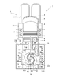
- FIG. 1 is a schematic diagram illustrating a side cross-section of the Stirling engine 1
- FIG. 2 is a schematic diagram illustrating a front cross-section of the Stirling engine 1.
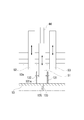
- FIG. 3 is an enlarged schematic view showing a part of the Stirling engine 1 of FIG.
- the ⁇ -type Stirling engine 1 will be described as an example.
- a Stirling engine 1 includes a displacer piston 3 and a power piston 4 that are reciprocally housed in a cylinder 2 in which a working gas such as air, helium gas, or hydrogen is sealed. ing.
- the cylinder 2 has a configuration in which one end is opened and the other end is closed.
- a displacer piston 3 is arranged on the closed end side, and a power piston 4 is arranged on the open end side.
- an expansion space 5 is formed between the closed end and the displacer piston 3
- a compression space 6 is formed between the displacer piston 3 and the power piston 4.
- the expansion space 5 and the compression space 6 in the cylinder 2 are collectively referred to as a working space.
- the Stirling engine 1 is provided with a heat exchanger 7 that raises and lowers the temperature of the working gas in the working space in the cylinder 2.
- the heat exchanger 7 includes a heater 8 that communicates with the expansion space 5 and heats the working gas by heat input from outside, a cooler 9 that communicates with the compression space 6 and cools the working gas by heat radiation to the outside, and a heater 8 and a regenerator 10 that connects the cooler 9 to each other.
- the heater 8 has one end communicating with the expansion space 5 and the other end communicating with one end of the regenerator 10.
- the heater 8 heats the working gas passing through the inside by receiving heat of exhaust gas generated in an incinerator or the like. Although only two tubular heaters 8 are shown in FIGS. 1 and 2, a large number (three or more) of heaters 8 are actually provided.
- the other end of the regenerator 10 communicates with the cooler 9. Further, the cooler 9 communicates with the compression space 6. Cooling water flows in the cooler 9 so as to exchange heat with the working gas, and the working gas is cooled by this heat exchange.
- the regenerator 10 and the cooler 9 are arranged on the outer periphery of the cylinder 2.
- the regenerator 10 is composed of, for example, a laminate of metal fibers or a wire mesh, an array of working gas flow paths arranged in a honeycomb shape, or an envelope of cotton-like metal fibers. Functions as a regenerative heat exchanger. That is, the regenerator 10 stores the heat of the working gas when the high-temperature working gas flows from the heater 8 to the cooler 9, while stores the heat when the low-temperature working gas flows from the cooler 9 to the heater 8. Heat is released to the working gas.
- the Stirling engine 1 includes an output take-out device 11 that converts the reciprocating motion of the power piston 4 into rotational motion and outputs rotational power on the opening end side of the cylinder 2.
- the output take-out device 11 supports a crankshaft 12 connected to the displacer piston 3 and the power piston 4 in a crankcase 13.
- One end side of the crankshaft 12 serves as an output shaft, and is connected to the input shaft 16 of the generator 15 via the flywheel 14 in the crankcase 13.
- a buffer space 17 is formed by the space 17 a on the opening end side of the power piston 4 in the cylinder 2 and the space 17 b in the crankcase 13.
- the displacer piston 3 and the power piston 4 reciprocate in the cylinder 2 with a predetermined phase difference by being connected to the crankshaft 12 of the output take-out device 11.
- the phase difference in the reciprocating operation of the displacer piston 3 and the power piston 4 is 90 °.
- the output take-out device 11 includes a plate 51c fixed to a crankshaft guide groove (through groove) 51a of a displacer piston yoke 51 that reciprocates according to the displacer piston 3, and a power piston yoke that reciprocates according to the power piston 4 (
- the crank pins 54 to 56 of the crankshaft 12 are fitted to the plates 52c and 53c fixed to the crankshaft guide grooves (through grooves) 52a and 53a of the reciprocating motion portions 52 and 53 via bearings 57 to 59, respectively.
- the scotch-yoke mechanism The scotch-yoke mechanism.
- the displacer piston yoke 51 is provided with a crankshaft guide groove 51 a that is long in a direction (lateral direction) intersecting with the axial directions of the crankshaft 12 and the displacer piston 3 at the center portion thereof. Yes.
- Reciprocating guide holes (through holes) 51b are formed in both sides of the displacer piston yoke 51 across the crankshaft guide groove 51a in a direction along the axial direction of the displacer piston 3 (vertical direction).
- a guide shaft 60 fixed to the crankcase 13 is inserted into the reciprocating guide hole 51 b of the displacer piston yoke 51 via a linear motion bearing 63 such as a rotor rib bushing.
- the displacer piston yoke 51 is connected at one end to the other end of the rod 66 connected to the displacer piston 3, and reciprocates in the same direction (vertical direction) as the displacer piston 3 in accordance with the reciprocating motion of the displacer piston 3.
- the power piston yoke 52 is provided with a crankshaft guide groove 52a that is long in the lateral direction at the center thereof, and reciprocating guide holes (on both sides of the crankshaft guide groove 52a).
- a through-hole) 52b is formed in the vertical direction.
- a guide shaft 61 fixed to the crankcase 13 is inserted into the reciprocating guide hole 52 b of the power piston yoke 52 via a linear bearing 64.
- the power piston yoke 52 is connected at one end to the other end of the bridge 67 connected to the power piston 4, and reciprocates in the vertical direction in accordance with the reciprocation of the power piston 4. Since the power piston yoke 53 has the same shape as the power piston yoke 52, a detailed description thereof is omitted.
- through holes 4a and 67a are provided at the center of the power piston 4 and the bridge 67 in the direction (vertical direction) along the axial direction of the power piston 4, and the displacer piston 3 and A connected rod 66 is penetrated.
- the rod 66 is movable relative to the power piston 4 and the bridge 67, and a dynamic seal mechanism (not shown) such as a mechanical seal is formed at the insertion portion of the rod 66 in the power piston 4.
- the crankshaft 12 includes a crank pin 54 connected via a rod 66 and a displacer piston yoke 51 between a crank pin 55 and 56 connected via a bridge 67 and power piston yokes 52 and 53.
- the crankpin 54 is attached to the crankpins 55 and 56 having the same phase with a predetermined phase difference (for example, 90 °).
- a bridge insertion hole 68 into which the bridge 67 is inserted is provided at a portion of the crankcase 13 that is connected to the cylinder 2.
- the bridge insertion hole 68 of the crankcase 13 is formed at a connecting portion between the cylinder 2 and the crankcase 13, and the bridge 67 is configured such that the cylinder 2 side portion of the bridge 67 is inserted into and removed from the bridge insertion hole 68. Reciprocates according to the power piston 4. In order to reduce the fluctuation of the internal pressure due to the volume change accompanying the reciprocation of the power piston 4 in the buffer space 17a on the opening end side of the power piston 4 in the cylinder 2, the buffer space 17a in the cylinder 2 and the crankcase 13 A communication port 17d is provided between the buffer space 17b.
- the displacer piston 3 reciprocates with the rotational power of the crankshaft 12, and the working gas moves back and forth between the expansion space 5 and the compression space 6 to change the internal pressure of the working space. Due to this pressure change, the power piston 4 reciprocates and the reciprocating power is transmitted to the power piston yokes 52 and 53 via the bridge 67. Thereby, the power piston yokes 52 and 53 reciprocate in the vertical direction along the guide shafts 61 and 62, respectively. Then, the reciprocating motion of the power piston yokes 52 and 53 causes the crankshaft 12 to reciprocate in the lateral direction while rotating the crankpins 55 and 56 respectively in the crankshaft guide grooves 52a and 53a.
- the output take-out device 11 that receives the reciprocating power of the power piston 4 converts it into rotational power by the Scotch-yoke mechanism and outputs it from the crankshaft 12, and rotates the generator 15 via the flywheel 14 and the input shaft 16.
- the crankcase 13 includes a lubricating oil reservoir 13a that stores lubricating oil to be supplied to the sliding portion of the output take-out device 11.
- the lubricating oil reservoir 13 a is determined by the installation posture of the Stirling engine 1 and corresponds to the lower part in the vertical direction in the crankcase 13.
- An inner cylinder 131 is erected on the inner surface of the crankcase 13 and in the lubricating oil reservoir 13a. As shown in FIG. 1, the inner cylinder 131 extends in a direction (vertical direction) along the axial direction of the displacer piston 3.
- the inner cylinder 131 is configured to accommodate at least a part of the displacer piston yoke 51 or the power piston yokes 52 and 53 when the displacer piston 3 or the power piston 4 is located at the bottom dead center. That is, the displacer piston yoke 51 or the power piston yokes 52 and 53 correspond to the connecting member of the present invention.
- the inner cylinder 131 is disposed so as to accommodate a part of the displacer piston yoke 51.
- a side surface 131 a of the inner cylinder 131 is disposed between the displacer piston yoke 51 and the power piston yokes 52 and 53.
- the side surface 131a of the inner cylinder 131 is formed with at least one side hole 132 that communicates the inside and outside of the inner cylinder 131.
- the side hole 132 functions as a suction hole for sucking lubricating oil into the inner cylinder 131.
- a first communication hole 133 that communicates the inside and outside of the crankcase 13 is formed on the inner surface of the crankcase 13 surrounded by the inner cylinder 131.
- the first communication hole 133 functions as a discharge hole for discharging the lubricating oil to the outside of the crankcase 13.
- the opening area of the first communication hole 133 is preferably larger than the total opening area of the side holes 132. If the opening area of the first communication hole 133 is smaller than the total opening area of the side holes 132, the displacer piston yoke 51 moves in a direction approaching the first communication hole 133, and the pressure of the lubricating oil in the inner cylinder 131 increases. In this case, the lubricating oil is likely to be discharged out of the crankcase 13 from the side hole 132 instead of the first communication hole 133.
- a second communication hole 134 that communicates the inside and outside of the crankcase 13 is formed at a position on the inner surface of the crankcase 13 and away from the lubricating oil reservoir 13a. That is, the second communication hole 134 is provided at a position higher in the vertical direction than the oil level of the lubricating oil in the crankcase 13.
- the second communication hole 134 functions as a return hole for returning the lubricating oil discharged from the first communication hole 133 to the crankcase 13.
- the first communication hole 133 and the second communication hole 134 are connected by a lubricating oil path 135 provided outside the crankcase 13.
- the lubricating oil discharged from the first communication hole 133 flows to the second communication hole 134 through the lubricating oil path 135.
- the lubricating oil path 135 is provided with a check valve 136 having a forward direction from the first communication hole 133 toward the second communication hole 134. By providing the check valve 136, it is possible to prevent the lubricating oil in the lubricating oil path 135 from flowing back to the first communication hole 133 side.
- an oil meter 137 is provided on the second communication hole 134 side of the check valve 136.
- the oil meter 137 can measure the flow rate of the lubricating oil flowing through the lubricating oil path 135. Thereby, the presence or absence of the lubricating oil in the crankcase 13 circulating through the lubricating oil path 135 can be confirmed.
- a turbine flow meter can be used as the oil amount meter 137.
- the oil meter 137 may output a signal depending on the presence or absence of lubricating oil.
- the Stirling engine 1 extends from the inner surface of the crankcase 13 closer to the lubricating oil reservoir 13a than the second communication hole 134 to a position facing away from the second communication hole 134 and covers the second communication hole 134. It is preferable to further include a double communication hole cover 134a. Accordingly, it is possible to prevent the lubricating oil stirred in the crankcase 13 during driving of the engine from entering the second communication hole 134 and flowing back through the lubricating oil path 135. The presence or absence of lubricating oil can be accurately confirmed.
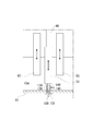
- FIG. 4 is an enlarged schematic view showing a part of the Stirling engine 1 according to the second embodiment.
- This Stirling engine 1 is provided inside the barrel 138 on the inner surface of the crankcase 13 and standing in the lubricating oil reservoir 13a, and the displacer piston 3 or the power piston 4 moves to the bottom dead center.
- a plunger 139 that is sometimes pressed by the displacer piston yoke 51 or the power piston yokes 52 and 53, at least one side hole 140 that is formed on the side surface of the barrel 138 and communicates with the inside and outside of the barrel 138, and is surrounded by the barrel 138
- a first communication hole 133 is formed on the inner surface of the crankcase 13 and communicates with the inside and outside of the crankcase 13.
- the Stirling engine 1 includes a second communication hole 134, a lubricating oil path 135, a check valve 136, and an oil meter 137, as in the first embodiment.
- the second embodiment as in the first embodiment, the presence or absence of lubricating oil in the crankcase 13 circulating through the lubricating oil path 135 can be confirmed.
- a return spring 141 that urges the plunger 139 in a direction away from the first communication hole 133 is provided in the barrel 138.
- the Stirling engine 1 is disposed so that the displacer piston yoke 51 and the power piston yokes 52 and 53 reciprocate in the vertical direction, and the output extraction device 11 is provided below the cylinder 2.
- the Stirling engine 1 is arranged so that the displacer piston yoke 51 and the power piston yokes 52 and 53 reciprocate in the horizontal direction, and the output take-out device 11 is disposed on the side of the cylinder 2. You may make it provide.
- the ⁇ -type Stirling engine 1 has been described.
- other types of Stirling engines such as ⁇ -type and ⁇ -type may be used.
Landscapes
- Engineering & Computer Science (AREA)
- Chemical & Material Sciences (AREA)
- Combustion & Propulsion (AREA)
- Mechanical Engineering (AREA)
- General Engineering & Computer Science (AREA)
- Lubrication Of Internal Combustion Engines (AREA)
Abstract
スターリングエンジン1は、ディスプレーサピストン3とクランク軸12とを連結するディスプレーサピストンヨーク51と、潤滑油貯留部13aを有するクランクケース13と、潤滑油貯留部13aに立設され、ディスプレーサピストン3が下死点に位置するときに、ディスプレーサピストンヨーク51の少なくとも一部を収容する内筒131と、内筒131の側面131aに形成される側面孔132と、内筒131に囲まれたクランクケース13の内面に形成される第1連通孔133と、クランクケース13の内面であって潤滑油貯留部13aから離れた位置に形成される第2連通孔134と、第1連通孔133と第2連通孔134を接続する潤滑油経路135と、潤滑油経路135に設けられる逆止弁136及び油量計137と、を備える。
Description
本発明は、スターリングエンジンに関する。
下記特許文献1は、ディスプレーサピストン及びパワーピストンを同一シリンダに収めるスターリングエンジンにおいて、ディスプレーサピストン及びパワーピストンと連結されるクランク軸をクランクケースに密閉し、クランクケース内に潤滑油を溜める構成を開示する。さらに、パワーピストンの往復動によるクランクケース内の圧力変動を利用して開閉する給油弁と油戻し弁を設けて潤滑油を循環させる構成を開示する。
ところで、通常(内燃式)のエンジンは、運転中の潤滑油の油量(有無)を油圧スイッチのオン・オフで検知する。一方、スターリングエンジンは、作動ガスとして不活性ガスを密閉している関係上、クランクケースの内圧が通常のエンジンより高く、このような静圧が高い状態では油圧スイッチによる潤滑油の油量検知が困難である。そして、焼却炉の煙道に据え付けて廃熱によってスターリングエンジンを運転する状況では、廃熱の供給を受ける期間、常に運転状態となるため、運転中における潤滑油の油量検知が必須である。
しかし、特許文献1は、エンジン作動時のクランクケース内の潤滑油の油量を確認する構成を一切開示していない。
そこで、本発明は上記課題に鑑み、エンジン作動時のクランクケース内の潤滑油の油量を精度よく確認することができるスターリングエンジンを提供することを目的とする。
本発明のスターリングエンジンは、往復動するディスプレーサピストン及びパワーピストンと、
前記ディスプレーサピストン及びパワーピストンと連結されるクランク軸と、
前記ディスプレーサピストン又は前記パワーピストンと前記クランク軸とを連結する連結部材と、
前記クランク軸を軸支するとともに、潤滑油を貯留する潤滑油貯留部を有するクランクケースと、
前記クランクケースの内面であって前記潤滑油貯留部に立設され、前記ディスプレーサピストン又は前記パワーピストンが下死点に位置するときに、前記連結部材の少なくとも一部を収容する内筒と、
前記内筒の側面に形成され、前記内筒の内外を連通する少なくとも一つの側面孔と、
前記内筒に囲まれた前記クランクケースの内面に形成され、前記クランクケースの内外を連通する第1連通孔と、
前記クランクケースの内面であって前記潤滑油貯留部から離れた位置に形成され、前記クランクケースの内外を連通する第2連通孔と、
前記第1連通孔と前記第2連通孔を前記クランクケースの外で接続する潤滑油経路と、
前記潤滑油経路に設けられ、前記第1連通孔から前記第2連通孔に向かう方向を順方向とする逆止弁と、
前記潤滑油経路であって前記逆止弁よりも前記第2連通孔側に設けられた油量計と、を備えるものである。
前記ディスプレーサピストン及びパワーピストンと連結されるクランク軸と、
前記ディスプレーサピストン又は前記パワーピストンと前記クランク軸とを連結する連結部材と、
前記クランク軸を軸支するとともに、潤滑油を貯留する潤滑油貯留部を有するクランクケースと、
前記クランクケースの内面であって前記潤滑油貯留部に立設され、前記ディスプレーサピストン又は前記パワーピストンが下死点に位置するときに、前記連結部材の少なくとも一部を収容する内筒と、
前記内筒の側面に形成され、前記内筒の内外を連通する少なくとも一つの側面孔と、
前記内筒に囲まれた前記クランクケースの内面に形成され、前記クランクケースの内外を連通する第1連通孔と、
前記クランクケースの内面であって前記潤滑油貯留部から離れた位置に形成され、前記クランクケースの内外を連通する第2連通孔と、
前記第1連通孔と前記第2連通孔を前記クランクケースの外で接続する潤滑油経路と、
前記潤滑油経路に設けられ、前記第1連通孔から前記第2連通孔に向かう方向を順方向とする逆止弁と、
前記潤滑油経路であって前記逆止弁よりも前記第2連通孔側に設けられた油量計と、を備えるものである。
本発明のスターリングエンジンにおいて、前記第1連通孔の開口面積は、前記側面孔の総開口面積よりも大きいことが好ましい。
本発明のスターリングエンジンは、前記第2連通孔よりも前記潤滑油貯留部側の前記クランクケースの内面から前記第2連通孔から離間して対向する位置まで延び、前記第2連通孔を覆う第2連通孔カバーをさらに備えることが好ましい。
また、本発明のスターリングエンジンは、往復動するディスプレーサピストン及びパワーピストンと、
前記ディスプレーサピストン及びパワーピストンと連結されるクランク軸と、
前記ディスプレーサピストン又は前記パワーピストンと前記クランク軸とを連結する連結部材と、
前記クランク軸を軸支するとともに、潤滑油を貯留する潤滑油貯留部を有するクランクケースと、
前記クランクケースの内面であって前記潤滑油貯留部に立設されるバレルと、
前記バレルの内部に設けられ、前記ディスプレーサピストン又は前記パワーピストンが下死点に移動するときに前記連結部材によって押圧されるプランジャと、
前記バレルの側面に形成され、前記バレルの内外を連通する少なくとも一つの側面孔と、
前記バレルに囲まれた前記クランクケースの内面に形成され、前記クランクケースの内外を連通する第1連通孔と、
前記クランクケースの内面であって前記潤滑油貯留部から離れた位置に形成され、前記クランクケースの内外を連通する第2連通孔と、
前記第1連通孔と前記第2連通孔を前記クランクケースの外で接続する潤滑油経路と、
前記潤滑油経路に設けられ、前記第1連通孔から前記第2連通孔に向かう方向を順方向とする逆止弁と、
前記潤滑油経路であって前記逆止弁よりも前記第2連通孔側に設けられた油量計と、を備えるものでもよい。
前記ディスプレーサピストン及びパワーピストンと連結されるクランク軸と、
前記ディスプレーサピストン又は前記パワーピストンと前記クランク軸とを連結する連結部材と、
前記クランク軸を軸支するとともに、潤滑油を貯留する潤滑油貯留部を有するクランクケースと、
前記クランクケースの内面であって前記潤滑油貯留部に立設されるバレルと、
前記バレルの内部に設けられ、前記ディスプレーサピストン又は前記パワーピストンが下死点に移動するときに前記連結部材によって押圧されるプランジャと、
前記バレルの側面に形成され、前記バレルの内外を連通する少なくとも一つの側面孔と、
前記バレルに囲まれた前記クランクケースの内面に形成され、前記クランクケースの内外を連通する第1連通孔と、
前記クランクケースの内面であって前記潤滑油貯留部から離れた位置に形成され、前記クランクケースの内外を連通する第2連通孔と、
前記第1連通孔と前記第2連通孔を前記クランクケースの外で接続する潤滑油経路と、
前記潤滑油経路に設けられ、前記第1連通孔から前記第2連通孔に向かう方向を順方向とする逆止弁と、
前記潤滑油経路であって前記逆止弁よりも前記第2連通孔側に設けられた油量計と、を備えるものでもよい。
本発明によれば、ディスプレーサピストン又はパワーピストンが下死点まで移動する区間では、第1連通孔を通じて潤滑油を油量計に向かって流すことができ、一方、ディスプレーサピストン又はパワーピストンが上死点まで移動する区間では、逆止弁によって潤滑油が潤滑油経路を逆流することを防止できるため、エンジン作動時のクランクケース内の潤滑油の油量を精度よく確認することができる。
以下に、本発明の実施形態について図面を参照しながら説明する。
[第1実施形態]
図1は、スターリングエンジン1の側面断面を示す概略図であり、図2は、スターリングエンジン1の正面断面を示す概略図である。また、図3は、図1のスターリングエンジン1の一部を拡大して示す模式図である。なお、以下では、β型のスターリングエンジン1を例に挙げて説明する。
図1は、スターリングエンジン1の側面断面を示す概略図であり、図2は、スターリングエンジン1の正面断面を示す概略図である。また、図3は、図1のスターリングエンジン1の一部を拡大して示す模式図である。なお、以下では、β型のスターリングエンジン1を例に挙げて説明する。
図1及び図2に示すように、スターリングエンジン1は、空気、ヘリウムガス、水素等の作動ガスが封入されたシリンダ2の内部に、ディスプレーサピストン3及びパワーピストン4がそれぞれ往復動可能に収容されている。
シリンダ2は、一端を開口する一方で他端を閉塞した構成で有り、閉塞端部側にディスプレーサピストン3を配置する一方、開口端部側にパワーピストン4を配置している。シリンダ2内には、閉塞端部とディスプレーサピストン3との間に膨張空間5が形成され、ディスプレーサピストン3とパワーピストン4との間に圧縮空間6が形成されている。なお、シリンダ2内の膨張空間5と圧縮空間6とを合わせて、作動空間と呼ぶ。
スターリングエンジン1は、シリンダ2内の作動空間における作動ガスの温度を昇降させる熱交換器7が配設されている。熱交換器7は、膨張空間5と連通して外部からの入熱により作動ガスを加熱するヒータ8と、圧縮空間6と連通して外部への放熱により作動ガスを冷却するクーラ9と、ヒータ8とクーラ9とを連結する再生器10とを備えている。ディスプレーサピストン3がシリンダ2の開口端部側に向けて移動すると、ヒータ8で加熱された作動ガスが膨張空間5に流入することで、作動ガスの温度が上昇する。一方、ディスプレーサピストン3がシリンダ2の閉塞端部側に向けて移動すると、クーラ9で冷却された作動ガスが圧縮空間6に流入することで、作動ガスの温度が低下する。従って、熱交換器7とシリンダ2内の作動空間との間で作動ガスが順逆に流れることで、シリンダ2の作動空間における内圧が変化し、パワーピストン4の往復動を促す。
ヒータ8は、一端部が膨張空間5に連通し、他端部が再生器10の一端部に連通している。ヒータ8は、焼却炉等で発生する排ガスの熱を受けることで、内部を通過する作動ガスを加熱する。図1及び図2では、管状のヒータ8を2個のみ示しているが、実際には多数(3個以上)のヒータ8が設けられている。
再生器10の他端部はクーラ9に連通している。また、クーラ9は圧縮空間6に連通している。クーラ9内には作動ガスと熱交換可能に冷却水が流れており、この熱交換によって作動ガスを冷却する。
再生器10及びクーラ9は、シリンダ2の外周部に配置されている。再生器10は、例えば、金属繊維や金網を積層させたものや、作動ガスの流路をハニカム形状などで配列させたものや、綿状金属繊維を内包させたものなどで構成されており、蓄熱式熱交換器として機能する。すなわち、再生器10は、ヒータ8からクーラ9に高温の作動ガスが流れる際には、作動ガスの熱を蓄熱する一方で、クーラ9からヒータ8に低温の作動ガスが流れる際には、蓄熱した熱を作動ガスに放熱する。
スターリングエンジン1は、シリンダ2の開口端部側に、パワーピストン4の往復動作を回転動作に変換して回転動力を出力する出力取り出し装置11を備える。出力取り出し装置11は、ディスプレーサピストン3及びパワーピストン4それぞれと連結したクランク軸12をクランクケース13内に軸支させている。そして、クランク軸12の一端側が出力軸となり、クランクケース13内で、フライホイール14を介して発電機15の入力軸16と連結されている。また、シリンダ2内におけるパワーピストン4より開口端部側の空間17aと、クランクケース13内の空間17bとにより、バッファ空間17を形成している。
ディスプレーサピストン3及びパワーピストン4は、出力取り出し装置11のクランク軸12と接続することで、シリンダ2内を互いに所定の位相差で往復動する。なお、本実施形態では、ディスプレーサピストン3及びパワーピストン4の往復動作における位相差を90°としている。
出力取り出し装置11は、ディスプレーサピストン3に合わせて往復動するディスプレーサピストンヨーク51のクランク軸案内溝(貫通溝)51aに固定されたプレート51cと、パワーピストン4に合わせて往復動するパワーピストンヨーク(往復動部)52,53のクランク軸案内溝(貫通溝)52a,53aに固定されたプレート52c,53cのそれぞれに、軸受57~59を介してクランク軸12のクランクピン54~56が嵌合わされたスコッチ・ヨーク機構で構成されている。
図2に示すように、ディスプレーサピストンヨーク51は、その中央部分に、クランク軸12及びディスプレーサピストン3それぞれの軸方向に対して交差する方向(横方向)に長いクランク軸案内溝51aが設けられている。ディスプレーサピストンヨーク51におけるクランク軸案内溝51aを挟んだ両側部には、ディスプレーサピストン3の軸方向に沿う方向(縦方向)に、往復動案内穴(貫通穴)51bが穿設されている。そして、ディスプレーサピストンヨーク51の往復動案内穴51bには、ロータリブッシングなどの直動軸受63を介して、クランクケース13に固定されたガイド軸60が挿入されている。ディスプレーサピストンヨーク51は、一端がディスプレーサピストン3と連結したロッド66の他端と連結しており、ディスプレーサピストン3の往復動に合わせて、ディスプレーサピストン3と同一方向(縦方向)で往復動する。
図2に示すように、パワーピストンヨーク52は、その中央部分に、横方向に長いクランク軸案内溝52aが設けられており、クランク軸案内溝52aを挟んだ両側部に、往復動案内穴(貫通穴)52bが縦方向に穿設されている。そして、パワーピストンヨーク52の往復動案内穴52bには、直動軸受64を介して、クランクケース13に固定されたガイド軸61が挿入されている。パワーピストンヨーク52は、一端がパワーピストン4と連結したブリッジ67の他端と連結しており、パワーピストン4の往復動に合わせて縦方向で往復動する。パワーピストンヨーク53は、パワーピストンヨーク52と同様の形状をしているため、詳細な説明は省略する。
図1及び図2に示すように、パワーピストン4及びブリッジ67の中心には、パワーピストン4の軸方向に沿う方向(縦方向)に貫通穴4a,67aが設けられており、ディスプレーサピストン3と連結したロッド66が貫装されている。ロッド66は、パワーピストン4及びブリッジ67と相対的に移動可能であるとともに、パワーピストン4におけるロッド66の挿入部分にメカニカルシールなどによる動的シール機構(図示省略)が構成されている。
図1に示すように、クランク軸12は、ブリッジ67とパワーピストンヨーク52,53を介して連結したクランクピン55,56の間に、ロッド66とディスプレーサピストンヨーク51を介して連結したクランクピン54を設けており、同位相のクランクピン55,56に対して所定の位相差(例えば、90°)でクランクピン54が取り付けられている。クランクケース13におけるシリンダ2との連結部分には、ブリッジ67が嵌挿されるブリッジ挿入穴68が設けられている。クランクケース13のブリッジ挿入穴68は、シリンダ2とクランクケース13との連結部分に構成されており、ブリッジ67のシリンダ2側部分がブリッジ挿入穴68に対して挿脱するようにして、ブリッジ67がパワーピストン4に合わせて往復動する。シリンダ2内におけるパワーピストン4より開口端部側のバッファ空間17aにおける、パワーピストン4の往復動に伴う容積変化による内圧の変動を低減する為に、シリンダ2内のバッファ空間17aとクランクケース13内のバッファ空間17bとの間に連通口17dを設けている。
ディスプレーサピストン3は、クランク軸12の回転動力で往復動し、作動ガスが膨張空間5と圧縮空間6の間を行き来して、作動空間の内圧が変化する。この圧力変化によりパワーピストン4が往復動し、その往復動力がブリッジ67を介してパワーピストンヨーク52,53に伝達される。これにより、パワーピストンヨーク52,53がそれぞれ、ガイド軸61,62のそれぞれに沿って縦方向に往復動する。そして、パワーピストンヨーク52,53それぞれの往復動により、クランク軸案内溝52a,53aそれぞれをクランクピン55,56それぞれが回転しながら横方向に往復することで、クランク軸12が回転する。従って、パワーピストン4の往復動力を受けた出力取り出し装置11は、スコッチ・ヨーク機構により回転動力に変換してクランク軸12より出力し、フライホイール14及び入力軸16を介して発電機15を回転させる。
クランクケース13は、出力取り出し装置11における摺動部分に供給するための潤滑油を貯留する潤滑油貯留部13aを備える。潤滑油貯留部13aは、スターリングエンジン1の設置姿勢によって決定され、クランクケース13内の鉛直方向下部に相当する。
クランクケース13の内面であって潤滑油貯留部13aには、内筒131が立設されている。内筒131は、図1に示すようにディスプレーサピストン3の軸方向に沿う方向(縦方向)に延びている。内筒131は、ディスプレーサピストン3又はパワーピストン4が下死点に位置するときに、ディスプレーサピストンヨーク51又はパワーピストンヨーク52,53の少なくとも一部を収容するように構成されている。すなわち、ディスプレーサピストンヨーク51又はパワーピストンヨーク52,53が本発明の連結部材に相当する。本実施形態では、内筒131は、ディスプレーサピストンヨーク51の一部を収容するように配置されている。内筒131の側面131aは、ディスプレーサピストンヨーク51とパワーピストンヨーク52,53の間に配置される。
内筒131の側面131aには、内筒131の内外を連通する少なくとも一つの側面孔132が形成されている。側面孔132は、潤滑油を内筒131内に吸入する吸入孔として機能する。
内筒131に囲まれたクランクケース13の内面には、クランクケース13の内外を連通する第1連通孔133が形成されている。第1連通孔133は、潤滑油をクランクケース13の外へ排出する排出孔として機能する。
ディスプレーサピストン3が下死点まで移動する区間、すなわちディスプレーサピストンヨーク51が第1連通孔133に接近する方向へ移動する区間では、内筒131内の潤滑油の圧力が高まり、図3に示すように第1連通孔133から潤滑油がクランクケース13の外へ排出される。一方、ディスプレーサピストン3が上死点まで移動する区間、すなわちディスプレーサピストンヨーク51が第1連通孔133から離隔する方向へ移動する区間では、内筒131内の潤滑油の圧力が下がり、内筒131内に潤滑油が流入する。このとき、内筒131の側面131aに側面孔132を設けているため、図3に示すように潤滑油が側面孔132から内筒131内に流入しやすい。
第1連通孔133の開口面積は、側面孔132の総開口面積よりも大きいことが好ましい。第1連通孔133の開口面積が側面孔132の総開口面積よりも小さいと、ディスプレーサピストンヨーク51が第1連通孔133に接近する方向へ移動し、内筒131内の潤滑油の圧力が高まった場合に、第1連通孔133ではなく側面孔132から潤滑油がクランクケース13の外へ排出されやすくなる。
クランクケース13の内面であって潤滑油貯留部13aから離れた位置には、クランクケース13の内外を連通する第2連通孔134が形成されている。すなわち、第2連通孔134は、クランクケース13内の潤滑油の油面よりも鉛直方向で高い位置に設けられている。第2連通孔134は、第1連通孔133から排出された潤滑油をクランクケース13に戻す戻し孔として機能する。
第1連通孔133と第2連通孔134は、クランクケース13の外に設けられた潤滑油経路135で接続されている。第1連通孔133から排出された潤滑油は、潤滑油経路135を介して第2連通孔134へ流れる。潤滑油経路135には、第1連通孔133から第2連通孔134に向かう方向を順方向とする逆止弁136が設けられている。逆止弁136を設けることにより、潤滑油経路135内の潤滑油が第1連通孔133側へ逆流することを防止できる。
また、潤滑油経路135には、逆止弁136よりも第2連通孔134側に油量計137が設けられている。油量計137は、潤滑油経路135を流れる潤滑油の流量を計測することができる。これにより、潤滑油経路135を介して循環するクランクケース13内の潤滑油の有無を確認することができる。なお、油量計137としては、例えばタービン流量計を用いることができる。また、油量計137は、潤滑油の有無により信号を出力するようにしてもよい。
また、スターリングエンジン1は、第2連通孔134よりも潤滑油貯留部13a側のクランクケース13の内面から第2連通孔134から離間して対向する位置まで延び、第2連通孔134を覆う第2連通孔カバー134aをさらに備えるのが好ましい。これにより、エンジンの駆動中にクランクケース13内で撹拌された潤滑油が、第2連通孔134から侵入して潤滑油経路135を逆流することを防止でき、油量計137によるクランクケース13内の潤滑油の有無を正確に確認することができる。
[第2実施形態]
図4は、第2実施形態に係るスターリングエンジン1の一部を拡大して示す模式図である。このスターリングエンジン1は、クランクケース13の内面であって潤滑油貯留部13aに立設されるバレル138と、バレル138の内部に設けられ、ディスプレーサピストン3又はパワーピストン4が下死点に移動するときにディスプレーサピストンヨーク51又はパワーピストンヨーク52,53によって押圧されるプランジャ139と、バレル138の側面に形成され、バレル138の内外を連通する少なくとも一つの側面孔140と、バレル138に囲まれたクランクケース13の内面に形成され、クランクケース13の内外を連通する第1連通孔133と、を備えている。また、このスターリングエンジン1は、第1実施形態と同様に、第2連通孔134と、潤滑油経路135と、逆止弁136と、油量計137と、を備えている。第2実施形態によれば、第1実施形態と同様に、潤滑油経路135を介して循環するクランクケース13内の潤滑油の有無を確認することができる。なお、バレル138内には、プランジャ139を第1連通孔133から離隔する方向へ付勢するリターンスプリング141が設けられている。
図4は、第2実施形態に係るスターリングエンジン1の一部を拡大して示す模式図である。このスターリングエンジン1は、クランクケース13の内面であって潤滑油貯留部13aに立設されるバレル138と、バレル138の内部に設けられ、ディスプレーサピストン3又はパワーピストン4が下死点に移動するときにディスプレーサピストンヨーク51又はパワーピストンヨーク52,53によって押圧されるプランジャ139と、バレル138の側面に形成され、バレル138の内外を連通する少なくとも一つの側面孔140と、バレル138に囲まれたクランクケース13の内面に形成され、クランクケース13の内外を連通する第1連通孔133と、を備えている。また、このスターリングエンジン1は、第1実施形態と同様に、第2連通孔134と、潤滑油経路135と、逆止弁136と、油量計137と、を備えている。第2実施形態によれば、第1実施形態と同様に、潤滑油経路135を介して循環するクランクケース13内の潤滑油の有無を確認することができる。なお、バレル138内には、プランジャ139を第1連通孔133から離隔する方向へ付勢するリターンスプリング141が設けられている。
[他の実施形態]
前述の第1及び第2実施形態では、ディスプレーサピストンヨーク51及びパワーピストンヨーク52,53が鉛直方向に往復動するようにスターリングエンジン1を配置し、シリンダ2の下方に出力取り出し装置11を設ける例を示したが、図5に示すように、ディスプレーサピストンヨーク51及びパワーピストンヨーク52,53が水平方向に往復動するようにスターリングエンジン1を配置し、シリンダ2の側方に出力取り出し装置11を設けるようにしてもよい。
前述の第1及び第2実施形態では、ディスプレーサピストンヨーク51及びパワーピストンヨーク52,53が鉛直方向に往復動するようにスターリングエンジン1を配置し、シリンダ2の下方に出力取り出し装置11を設ける例を示したが、図5に示すように、ディスプレーサピストンヨーク51及びパワーピストンヨーク52,53が水平方向に往復動するようにスターリングエンジン1を配置し、シリンダ2の側方に出力取り出し装置11を設けるようにしてもよい。
また、前述の第1及び第2実施形態では、β型のスターリングエンジン1に基づいて説明したが、α型やγ型等の他の形式のスターリングエンジンであっても構わない。
以上、本発明の実施形態について図面に基づいて説明したが、具体的な構成は、これらの実施形態に限定されるものでないと考えられるべきである。本発明の範囲は、上記した実施形態の説明だけではなく特許請求の範囲によって示され、さらに特許請求の範囲と均等の意味および範囲内でのすべての変更が含まれる。
1 スターリングエンジン
3 ディスプレーサピストン
4 パワーピストン
12 クランク軸
13 クランクケース
13a 潤滑油貯留部
51 ディスプレーサピストンヨーク
52 パワーピストンヨーク
53 パワーピストンヨーク
131 内筒
131a 側面
132 側面孔
133 第1連通孔
134 第2連通孔
134a 第2連通孔カバー
135 潤滑油経路
136 逆止弁
137 油量計
138 バレル
139 プランジャ
140 側面孔
3 ディスプレーサピストン
4 パワーピストン
12 クランク軸
13 クランクケース
13a 潤滑油貯留部
51 ディスプレーサピストンヨーク
52 パワーピストンヨーク
53 パワーピストンヨーク
131 内筒
131a 側面
132 側面孔
133 第1連通孔
134 第2連通孔
134a 第2連通孔カバー
135 潤滑油経路
136 逆止弁
137 油量計
138 バレル
139 プランジャ
140 側面孔
Claims (4)
- 往復動するディスプレーサピストン及びパワーピストンと、
前記ディスプレーサピストン及びパワーピストンと連結されるクランク軸と、
前記ディスプレーサピストン又は前記パワーピストンと前記クランク軸とを連結する連結部材と、
前記クランク軸を軸支するとともに、潤滑油を貯留する潤滑油貯留部を有するクランクケースと、
前記クランクケースの内面であって前記潤滑油貯留部に立設され、前記ディスプレーサピストン又は前記パワーピストンが下死点に位置するときに、前記連結部材の少なくとも一部を収容する内筒と、
前記内筒の側面に形成され、前記内筒の内外を連通する少なくとも一つの側面孔と、
前記内筒に囲まれた前記クランクケースの内面に形成され、前記クランクケースの内外を連通する第1連通孔と、
前記クランクケースの内面であって前記潤滑油貯留部から離れた位置に形成され、前記クランクケースの内外を連通する第2連通孔と、
前記第1連通孔と前記第2連通孔を前記クランクケースの外で接続する潤滑油経路と、
前記潤滑油経路に設けられ、前記第1連通孔から前記第2連通孔に向かう方向を順方向とする逆止弁と、
前記潤滑油経路であって前記逆止弁よりも前記第2連通孔側に設けられた油量計と、を備える、スターリングエンジン。 - 前記第1連通孔の開口面積は、前記側面孔の総開口面積よりも大きい、請求項1に記載のスターリングエンジン。
- 前記第2連通孔よりも前記潤滑油貯留部側の前記クランクケースの内面から前記第2連通孔から離間して対向する位置まで延び、前記第2連通孔を覆う第2連通孔カバーをさらに備える、請求項1又は2に記載のスターリングエンジン。
- 往復動するディスプレーサピストン及びパワーピストンと、
前記ディスプレーサピストン及びパワーピストンと連結されるクランク軸と、
前記ディスプレーサピストン又は前記パワーピストンと前記クランク軸とを連結する連結部材と、
前記クランク軸を軸支するとともに、潤滑油を貯留する潤滑油貯留部を有するクランクケースと、
前記クランクケースの内面であって前記潤滑油貯留部に立設されるバレルと、
前記バレルの内部に設けられ、前記ディスプレーサピストン又は前記パワーピストンが下死点に移動するときに前記連結部材によって押圧されるプランジャと、
前記バレルの側面に形成され、前記バレルの内外を連通する少なくとも一つの側面孔と、
前記バレルに囲まれた前記クランクケースの内面に形成され、前記クランクケースの内外を連通する第1連通孔と、
前記クランクケースの内面であって前記潤滑油貯留部から離れた位置に形成され、前記クランクケースの内外を連通する第2連通孔と、
前記第1連通孔と前記第2連通孔を前記クランクケースの外で接続する潤滑油経路と、
前記潤滑油経路に設けられ、前記第1連通孔から前記第2連通孔に向かう方向を順方向とする逆止弁と、
前記潤滑油経路であって前記逆止弁よりも前記第2連通孔側に設けられた油量計と、を備える、スターリングエンジン。
Applications Claiming Priority (2)
| Application Number | Priority Date | Filing Date | Title |
|---|---|---|---|
| JP2018098733A JP2019203440A (ja) | 2018-05-23 | 2018-05-23 | スターリングエンジン |
| JP2018-098733 | 2018-05-23 |
Publications (1)
| Publication Number | Publication Date |
|---|---|
| WO2019225640A1 true WO2019225640A1 (ja) | 2019-11-28 |
Family
ID=68615824
Family Applications (1)
| Application Number | Title | Priority Date | Filing Date |
|---|---|---|---|
| PCT/JP2019/020249 Ceased WO2019225640A1 (ja) | 2018-05-23 | 2019-05-22 | スターリングエンジン |
Country Status (2)
| Country | Link |
|---|---|
| JP (1) | JP2019203440A (ja) |
| WO (1) | WO2019225640A1 (ja) |
Citations (3)
| Publication number | Priority date | Publication date | Assignee | Title |
|---|---|---|---|---|
| JPS54180849U (ja) * | 1978-06-13 | 1979-12-21 | ||
| JPS56171614U (ja) * | 1980-05-23 | 1981-12-18 | ||
| JP2018066298A (ja) * | 2016-10-18 | 2018-04-26 | ヤンマー株式会社 | スターリングエンジン |
-
2018
- 2018-05-23 JP JP2018098733A patent/JP2019203440A/ja active Pending
-
2019
- 2019-05-22 WO PCT/JP2019/020249 patent/WO2019225640A1/ja not_active Ceased
Patent Citations (3)
| Publication number | Priority date | Publication date | Assignee | Title |
|---|---|---|---|---|
| JPS54180849U (ja) * | 1978-06-13 | 1979-12-21 | ||
| JPS56171614U (ja) * | 1980-05-23 | 1981-12-18 | ||
| JP2018066298A (ja) * | 2016-10-18 | 2018-04-26 | ヤンマー株式会社 | スターリングエンジン |
Also Published As
| Publication number | Publication date |
|---|---|
| JP2019203440A (ja) | 2019-11-28 |
Similar Documents
| Publication | Publication Date | Title |
|---|---|---|
| US8857173B2 (en) | Two piston, concentric cylinder, alpha free piston Stirling machine | |
| KR100862965B1 (ko) | 열기관 | |
| EP2628933A2 (en) | External combustion engine | |
| JP2009236456A (ja) | パルス管型蓄熱機関 | |
| JP2008101477A (ja) | スターリングエンジン発電機 | |
| JP4609577B2 (ja) | ピストン機関 | |
| KR100412299B1 (ko) | 가스 압축 팽창기 | |
| WO2019225640A1 (ja) | スターリングエンジン | |
| JP5181575B2 (ja) | スターリングエンジン | |
| JP2019206926A (ja) | スターリングエンジン | |
| JP6726079B2 (ja) | スターリングエンジン | |
| WO2020189440A1 (ja) | エンジン | |
| JP6626468B2 (ja) | スターリングエンジン | |
| JP7202365B2 (ja) | 段付ピストンを有する高温ガスエンジン | |
| JP6713403B2 (ja) | 出力取り出し装置、及びスターリングエンジン | |
| JP2018150822A (ja) | スターリングエンジン | |
| EP3530921A1 (en) | Stirling engine | |
| US20100064681A1 (en) | Method for increasing performance of a stirling or free-piston engine | |
| JP2021025418A (ja) | β型スターリングエンジン | |
| JP2006188956A (ja) | ピストン機関 | |
| JPH0444098B2 (ja) | ||
| JP2005337179A (ja) | スターリングエンジン | |
| JP3698986B2 (ja) | スターリング冷凍機 | |
| EP3530922A1 (en) | Stirling engine | |
| JP2018150823A (ja) | スターリングエンジン、その潤滑油排出方法、及びその潤滑油供給方法 |
Legal Events
| Date | Code | Title | Description |
|---|---|---|---|
| 121 | Ep: the epo has been informed by wipo that ep was designated in this application |
Ref document number: 19808280 Country of ref document: EP Kind code of ref document: A1 |
|
| NENP | Non-entry into the national phase |
Ref country code: DE |
|
| 122 | Ep: pct application non-entry in european phase |
Ref document number: 19808280 Country of ref document: EP Kind code of ref document: A1 |