WO2019225582A1 - センサモジュール、センサモジュールの製造方法、及び血圧測定装置 - Google Patents
センサモジュール、センサモジュールの製造方法、及び血圧測定装置 Download PDFInfo
- Publication number
- WO2019225582A1 WO2019225582A1 PCT/JP2019/020049 JP2019020049W WO2019225582A1 WO 2019225582 A1 WO2019225582 A1 WO 2019225582A1 JP 2019020049 W JP2019020049 W JP 2019020049W WO 2019225582 A1 WO2019225582 A1 WO 2019225582A1
- Authority
- WO
- WIPO (PCT)
- Prior art keywords
- sensor
- opening
- sensor module
- blood pressure
- wrist
- Prior art date
- Legal status (The legal status is an assumption and is not a legal conclusion. Google has not performed a legal analysis and makes no representation as to the accuracy of the status listed.)
- Ceased
Links
Images


Classifications
-
- A—HUMAN NECESSITIES
- A61—MEDICAL OR VETERINARY SCIENCE; HYGIENE
- A61B—DIAGNOSIS; SURGERY; IDENTIFICATION
- A61B5/00—Measuring for diagnostic purposes; Identification of persons
- A61B5/02—Detecting, measuring or recording for evaluating the cardiovascular system, e.g. pulse, heart rate, blood pressure or blood flow
- A61B5/021—Measuring pressure in heart or blood vessels
- A61B5/02141—Details of apparatus construction, e.g. pump units or housings therefor, cuff pressurising systems, arrangements of fluid conduits or circuits
-
- A—HUMAN NECESSITIES
- A61—MEDICAL OR VETERINARY SCIENCE; HYGIENE
- A61B—DIAGNOSIS; SURGERY; IDENTIFICATION
- A61B5/00—Measuring for diagnostic purposes; Identification of persons
- A61B5/02—Detecting, measuring or recording for evaluating the cardiovascular system, e.g. pulse, heart rate, blood pressure or blood flow
- A61B5/021—Measuring pressure in heart or blood vessels
- A61B5/022—Measuring pressure in heart or blood vessels by applying pressure to close blood vessels, e.g. against the skin; Ophthalmodynamometers
- A61B5/0225—Measuring pressure in heart or blood vessels by applying pressure to close blood vessels, e.g. against the skin; Ophthalmodynamometers the pressure being controlled by electric signals, e.g. derived from Korotkoff sounds
-
- A—HUMAN NECESSITIES
- A61—MEDICAL OR VETERINARY SCIENCE; HYGIENE
- A61B—DIAGNOSIS; SURGERY; IDENTIFICATION
- A61B5/00—Measuring for diagnostic purposes; Identification of persons
- A61B5/68—Arrangements of detecting, measuring or recording means, e.g. sensors, in relation to patient
- A61B5/6801—Arrangements of detecting, measuring or recording means, e.g. sensors, in relation to patient specially adapted to be attached to or worn on the body surface
- A61B5/6802—Sensor mounted on worn items
- A61B5/681—Wristwatch-type devices
-
- A—HUMAN NECESSITIES
- A61—MEDICAL OR VETERINARY SCIENCE; HYGIENE
- A61B—DIAGNOSIS; SURGERY; IDENTIFICATION
- A61B5/00—Measuring for diagnostic purposes; Identification of persons
- A61B5/68—Arrangements of detecting, measuring or recording means, e.g. sensors, in relation to patient
- A61B5/6801—Arrangements of detecting, measuring or recording means, e.g. sensors, in relation to patient specially adapted to be attached to or worn on the body surface
- A61B5/6813—Specially adapted to be attached to a specific body part
- A61B5/6824—Arm or wrist
-
- A—HUMAN NECESSITIES
- A61—MEDICAL OR VETERINARY SCIENCE; HYGIENE
- A61B—DIAGNOSIS; SURGERY; IDENTIFICATION
- A61B5/00—Measuring for diagnostic purposes; Identification of persons
- A61B5/68—Arrangements of detecting, measuring or recording means, e.g. sensors, in relation to patient
- A61B5/6801—Arrangements of detecting, measuring or recording means, e.g. sensors, in relation to patient specially adapted to be attached to or worn on the body surface
- A61B5/6843—Monitoring or controlling sensor contact pressure
-
- A—HUMAN NECESSITIES
- A61—MEDICAL OR VETERINARY SCIENCE; HYGIENE
- A61B—DIAGNOSIS; SURGERY; IDENTIFICATION
- A61B2562/00—Details of sensors; Constructional details of sensor housings or probes; Accessories for sensors
- A61B2562/04—Arrangements of multiple sensors of the same type
- A61B2562/043—Arrangements of multiple sensors of the same type in a linear array
-
- A—HUMAN NECESSITIES
- A61—MEDICAL OR VETERINARY SCIENCE; HYGIENE
- A61B—DIAGNOSIS; SURGERY; IDENTIFICATION
- A61B2562/00—Details of sensors; Constructional details of sensor housings or probes; Accessories for sensors
- A61B2562/12—Manufacturing methods specially adapted for producing sensors for in-vivo measurements
Definitions
- the present invention relates to a sensor module for measuring blood pressure, a method for manufacturing the sensor module, and a blood pressure measuring device.
- blood pressure measuring devices used for blood pressure measurement are used not only in medical facilities but also in the home as a means for confirming the health condition.
- a technique using an oscillometric method for example, a technique using a tonometry method, and the like are known (for example, see Patent Document 1).
- a blood pressure measurement device using an oscillometric method detects the pressure of a cuff wound around the upper arm or wrist of a living body with a pressure sensor, thereby detecting the vibration of the arterial wall and measuring the blood pressure.
- the blood pressure measuring device using the tonometry method measures blood pressure by bringing a sensor module including a plurality of pressure sensors into contact with the wrist in a region where the artery of the wrist exists.
- the sensor module includes, for example, a sensor base on which the pressure sensor is mounted, a sensor head cover that covers the sensor base and has an opening at a position facing the pressure sensor, and a soft resin that is disposed in the opening of the sensor head cover and covers the surface of the pressure sensor The soft part comprised by these.
- the soft portion is formed by injecting a relatively soft resin material such as silicone resin from the opening of the cover.
- a method of forming a soft part by arranging a pressure sensor on the surface of the sensor base, assembling the sensor head cover on the sensor base, and injecting a soft resin from the surface side of the opening of the sensor head cover is known. Since the soft part directly contacts a living body such as a wrist, the surface of the soft part needs to be configured flat. For this reason, when the soft resin is injected from the surface side, the surface is molded by pressing the smooth plate against the opening on the surface side immediately after the injection of the resin. Therefore, the manufacturing process becomes complicated, and a load is applied to the pressure sensor when pressing the smooth plate, which may cause a decrease in sensor accuracy.
- an object of the present invention is to provide a sensor module, a method for manufacturing the sensor module, and a blood pressure measurement device that can ensure high sensor accuracy with high smoothness of the surface in contact with the sensing object.
- the sensor wall and the support wall portion in which the sensor portion is arranged on one main surface side and a flow hole penetrating from the one main surface side to the other main surface side is formed.
- a sensor base having an opening at a position facing the sensor portion, and disposed on one main surface side of the support wall portion of the sensor base via the flow hole and a gap communicating with the opening.
- a sensor module comprising a sensor head cover, and a soft part disposed in the opening and covering the sensor part.
- the process of forming the soft portion is facilitated by filling the soft resin from the other main surface side of the sensor base with a smooth surface provided in the opening. Therefore, for example, a process can be simplified and a surface with high smoothness can be formed as compared with a process of filling a soft resin from the opening side of one main surface and then pressing a smooth surface against the opening. In addition, the load on the sensor unit can be reduced, and high sensor accuracy can be ensured.
- a sensor module in which a plurality of the flow holes are arranged asymmetrically with respect to the sensor unit in an outer periphery of a region where the sensor unit is arranged.
- the flow of the soft resin can be defined, the soft part can be reliably filled on the surface of the sensor part, and a weld line is not generated in an inconvenient place. I can control it.
- a sensor module in which at least one of the flow holes has an opening area different from that of other flow holes.
- the soft resin can be injected from any one of the plurality of flow holes having different opening areas, and air and excess resin can be discharged from the other flow holes, so that the flow of the soft resin is easily defined.
- the sensor unit includes a pressure-sensitive element array having one or more pressure-sensitive elements, and 1 or 2 is provided on each side of the pressure-sensitive element array extending in a predetermined first direction.
- a sensor module in which a plurality of the flow holes are formed, and the total opening area of the flow holes on one side is larger than the total opening area of the flow holes on the other side.
- the soft resin can be injected from the side circulation hole having a large opening area, and air and excess resin can be discharged from the other side circulation hole, so that the flow of the soft resin is from one to the other. Therefore, it is possible to prevent a weld line from being generated in the center sensor part of the sensor part of the soft part.
- a sensor module in which a surface of the front sensor head cover facing the sensor base has an inclined surface inclined toward the opening.
- the soft resin easily flows into the opening due to the inclined surface, and the soft portion can be easily formed.
- a sensing main body including a case that houses the sensor module, and a shape that is provided at a position facing a region where one artery of the wrist exists and is capable of palpating the wrist
- a blood pressure measurement device including an attachment portion having an opening portion and an end portion that is curved to follow the shape of a part of the wrist in the circumferential direction, and a fixture provided in the attachment portion.
- the sensor module in the blood pressure measurement device, can be easily attached, and the pressure of the artery can be measured at a suitable position.
- the sensor base is disposed on one main surface side
- the sensor base includes a support wall portion on which a through hole penetrating from the one main surface side to the other main surface side is disposed, and the sensor A sensor head cover having an opening at a position facing the portion is disposed so as to face one side downward with a gap communicating with the one main surface of the sensor base and the flow hole and the opening.
- the other main surface side of at least one of the flow holes in a state where a facing member having a flat surface is brought into contact with the bottom of the sensor head cover and the opening is closed by the flat surface of the facing member
- a method for manufacturing a sensor module is provided, which includes the step of supplying a resin material from
- the step of forming the soft portion is facilitated by filling the soft resin from the other main surface side of the sensor base in a state where the opening has a smooth surface.
- the flow of the soft resin can be defined by injecting the soft resin from any of the unevenly arranged flow holes, and the surface of the sensor part can be reliably filled with the soft part, and the surface with high smoothness Can be formed. Therefore, for example, the process can be simplified, the load on the sensor unit can be reduced, and high sensor accuracy can be ensured, compared to the process of filling soft resin from the opening side of one main surface and then pressing the smooth surface against the opening. .
- the present invention can provide a sensor module, a method for manufacturing the sensor module, and a blood pressure measurement device that have high surface smoothness and can ensure high sensor accuracy.
- FIG. 1 is a perspective view showing a configuration of a blood pressure measurement device according to an embodiment of the present invention.
- FIG. 2 is a block diagram showing the configuration of the blood pressure measurement device.
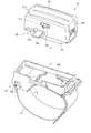
- FIG. 3 is a perspective view showing a configuration of a sensor device of the blood pressure measurement device.
- FIG. 4 is a perspective view showing a configuration of a part of the sensor device of the blood pressure measurement device.
- FIG. 5 is a perspective view showing a configuration of a sensor unit of the blood pressure measurement device.
- FIG. 6 is a plan view showing the configuration of the sensor unit.
- FIG. 7 is a cross-sectional view showing configurations of a sensor module and an air bag of the sensor unit.
- FIG. 1 is a perspective view showing a configuration of a blood pressure measurement device according to an embodiment of the present invention.
- FIG. 2 is a block diagram showing the configuration of the blood pressure measurement device.
- FIG. 3 is a perspective view showing a configuration of a sensor device of the blood pressure measurement device.
- FIG. 8 is a cross-sectional view showing a configuration of a sensor module and an air bag of the sensor unit.
- FIG. 9 is a cross-sectional view showing a configuration of a sensor module and an air bag of the sensor unit.
- FIG. 10 is a cross-sectional view showing the configuration of the blood pressure measurement device as worn on the wrist.
- FIG. 11 is a cross-sectional view showing the configuration of the blood pressure measurement device as worn on the wrist.
- FIG. 12 is a cross-sectional view showing the configuration of the blood pressure measurement device as worn on the wrist.
- FIG. 13 is a cross-sectional view showing a configuration of a sensor module of the sensor unit.
- FIG. 14 is a cross-sectional view showing the configuration of the sensor module.
- FIG. 15 is an explanatory diagram illustrating a partial configuration of the sensor module.
- FIG. 16 is a plan view showing a configuration of a sensor module of the sensor unit.
- FIG. 17 is a perspective view showing a partial configuration of the sensor module.
- FIG. 18 is a plan view showing the configuration of the sensor module.
- FIG. 19 is an explanatory diagram showing an example of a method for manufacturing the sensor module.
- FIG. 20 is an explanatory diagram showing a filling process of the method for manufacturing the sensor unit.
- FIG. 21 is a perspective view showing the configuration of the sensor module.
- FIG. 22 is an explanatory diagram showing position adjustment of the sensor unit of the blood pressure measurement device.
- FIG. 23 is a flowchart showing an example of blood pressure measurement using the blood pressure measurement device.
- FIG. 23 is a flowchart showing an example of blood pressure measurement using the blood pressure measurement device.
- FIG. 24 is an explanatory diagram showing an example of blood pressure measurement using the blood pressure measurement device.
- FIG. 25 is an explanatory diagram showing an example of blood pressure measurement using the blood pressure measurement device.
- FIG. 26 is an explanatory diagram showing an example of blood pressure measurement using the blood pressure measurement device.
- FIG. 27 is an explanatory view showing a method for manufacturing a sensor module of a blood pressure measurement device according to another embodiment of the present invention.
- FIG. 28 is a perspective view showing a configuration of a blood pressure measurement device according to another embodiment of the present invention.
- FIG. 29 is a block diagram showing a configuration of the blood pressure measurement apparatus.
- FIG. 30 is a perspective view showing a configuration of a blood pressure measurement device according to another embodiment of the present invention.
- FIG. 1 is a perspective view showing a configuration of a blood pressure measurement device 1 according to an embodiment of the present invention with a main body fixture 16 closed.
- FIG. 2 is a block diagram illustrating a configuration of the blood pressure measurement device 1.
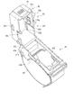
- FIG. 3 is a perspective view showing the configuration of the sensor device 5 of the blood pressure measurement device 1 with the sensing body 42 opened.
- FIG. 4 is a perspective view illustrating a configuration in which the sensor unit 52 is removed from the sensor device 5 of the blood pressure measurement device 1.
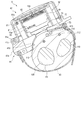
- FIG. 5 is a perspective view showing the configuration of the sensor unit 52 of the blood pressure measurement device 1.
- FIG. 6 is a plan view showing the configuration of the sensor unit 52.
- FIG. 1 is a perspective view showing a configuration of a blood pressure measurement device 1 according to an embodiment of the present invention with a main body fixture 16 closed.
- FIG. 2 is a block diagram illustrating a configuration of the blood pressure measurement device 1.
- FIG. 3 is a perspective view showing the configuration of the sensor device 5 of the blood pressure
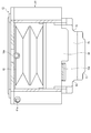
- FIG. 7 is a cross-sectional view showing the configuration of the sensor module 63 and the air bag 62 of the sensor unit 52 along the line VII-VII in FIG.
- FIG. 8 is a cross-sectional view showing the configuration of the sensor module 63 and the air bladder 62 along the line VIII-VIII in FIG.
- FIG. 9 is a cross-sectional view showing the configuration of the sensor module 63 and the air bladder 62 in the cross section taken along line IX-IX in FIG. 10 to 12 are cross-sectional views showing a state in which the configuration of the blood pressure measurement device 1 is attached to the wrist 100.
- 13 and 14 are cross-sectional views showing the configuration of the sensor module 63 of the sensor unit 52.
- FIG. 15 is an explanatory diagram illustrating a partial configuration of the sensor module 63
- FIG. 16 is a plan view illustrating the configuration of the sensor module 63.
- the radial artery of the wrist 100 is denoted by 110
- the radial bone is denoted by 111
- the ulnar artery is denoted by 112
- the ulna is denoted by 113
- the tendon is denoted by 114.
- the blood pressure measurement device 1 is an electronic blood pressure measurement device that is attached to a wrist 100 of a living body and calculates a blood pressure value from the pressure of the radial artery 110. As shown in FIGS. 1 to 16, the blood pressure measurement device 1 includes a device body 4 and a sensor device 5. For example, in the blood pressure measurement device 1, the sensor device 5 is attached to a region of the wrist 100 where the radial artery 110 exists, and the device body 4 is attached to the wrist 100 adjacent to the elbow side of the sensor device 5.
- Such a blood pressure measurement device 1 measures the pressure pulse wave pressure for each heartbeat that changes in conjunction with the heartbeat of the radial artery 110 by compressing the radial artery 110 with the sensor device 5, and the measured pressure Is processed by the apparatus main body 4 based on the tonometry method to determine the blood pressure.
- the apparatus main body 4 includes a main body case 11, an operation unit 12, a display unit 13, a pump 14, a control board 15, and a main body fixture 16. Further, for example, the apparatus main body 4 may be configured to include a cuff in the main body fixture 16 and press the wrist 100 during blood pressure measurement.
- the main body case 11 accommodates a part of the operation unit 12, a part of the display unit 13, and the control board 15, and exposes a part of the operation unit 12 and a part of the display unit 13 from the outer surface. .
- the main body case 11 is attached with a main body fixing tool 16.
- the operation unit 12 is configured to be able to input a command from the user.
- the operation unit 12 includes a plurality of buttons 21 provided on the main body case 11 and a sensor that detects an operation of the buttons 21.
- the operation unit 12 may be a touch panel and may be provided on the display unit 13.
- the operation unit 12 converts a command into an electric signal when operated by a user.
- the sensor that detects the operation of the button 21 is electrically connected to the control board 15 and outputs an electrical signal to the control board 15.
- the display unit 13 is disposed on the main body case 11 so as to be exposed from the outer surface of the main body case 11.
- the display unit 13 is electrically connected to the control board 15.
- the display unit 13 is, for example, a liquid crystal display or an organic electroluminescence display.
- the display unit 13 displays various information including blood pressure values such as date and time, maximum blood pressure, and minimum blood pressure, and measurement results such as heart rate.
- the pump 14 is, for example, a piezoelectric pump.
- the pump 14 has a tube 14a connected to the sensor device 5, compresses air, and supplies the compressed air to the sensor device 5 through the tube 14a.
- the pump 14 is electrically connected to the control board 15.
- the control board 15 includes, for example, a communication unit 31, a storage unit 32, and a control unit 33.
- the control board 15 is configured by mounting the communication unit 31, the storage unit 32, and the control unit 33 on the board.
- the control board 15 is connected to the sensor device 5 via a cable 15a.
- the cable 15 a is disposed outside the main body case 11 through a part of the outer surface of the main body case 11.
- the cable 15 a is arranged in the sensor device 5 from the inside of the main body case 11 through an opening provided on the side surface of the main body case 11.
- the communication unit 31 is configured to be able to transmit and receive information with an external device wirelessly or by wire.
- the communication unit 31 transmits, for example, information controlled by the control unit 33 and information such as measured blood pressure value and pulse to an external device via a network, and software from the external device via the network.
- An update program is received and sent to the control unit.
- the network is, for example, the Internet, but is not limited to this, and may be a network such as a LAN (Local Area Network) provided in a hospital, or a predetermined standard such as USB. It may be a direct wired communication with an external device using a cable having a terminal. Therefore, the communication unit 31 may include a plurality of wireless antennas and micro USB connectors.
- LAN Local Area Network
- USB Universal Serial Bus
- the storage unit 32 calculates a blood pressure value and a pulse from program data for controlling the entire blood pressure measurement device 1, setting data for setting various functions of the blood pressure measurement device 1, and pressure measured by the pressure-sensitive element 71c.
- the calculation data and the like for this are stored in advance. Further, the storage unit 32 stores information such as the calculated blood pressure value, the pulse, and time series data in which these calculated data are associated with time.
- the control unit 33 is configured by, for example, one or a plurality of CPUs (Central Processing Units), and controls the entire operation of the blood pressure measurement device 1 and performs each process based on the program data.
- the control unit 33 is electrically connected to the operation unit 12, the display unit 13, the pump 14, and the sensor device 5, and controls the operation of each component, transmits / receives signals, or supplies power.
- the main body fixing tool 16 includes, for example, one or a plurality of band-shaped bands and a fixing member such as a hook-and-loop fastener that wraps the band around the wrist 100 and fixes the main body case 11 to the wrist 100.
- a fixing member such as a hook-and-loop fastener that wraps the band around the wrist 100 and fixes the main body case 11 to the wrist 100.
- blood pressure data is continuously generated from the pulse wave of the radial artery 110 detected by the sensor device 5 by the control unit 33 performing processing using the program data stored in the storage unit 32.
- the blood pressure data includes blood pressure waveform data corresponding to the measured pulse wave waveform.
- the blood pressure data may further include time-series data of blood pressure feature amounts (blood pressure values). Examples of the blood pressure feature amount include, but are not limited to, systolic blood pressure (SBP) and diastolic blood pressure (DBP).
- SBP systolic blood pressure
- DBP diastolic blood pressure
- the maximum value in the pulse waveform for one heartbeat corresponds to systolic blood pressure
- the minimum value in the pulse waveform for one heartbeat corresponds to diastolic blood pressure.
- the apparatus main body 4 measures a pressure pulse wave as a pulse wave by a tonometry method.
- the tonometry method is a method in which the radial artery 110 is pressed from above the skin with an appropriate pressure to form a flat portion in the radial artery 110, and the sensor device 5 is in a state where the inside and outside of the radial artery 110 are balanced. This is a method of measuring pressure pulse waves. According to the tonometry method, blood pressure values for each heartbeat can be obtained.
- the sensor device 5 includes an attach part 41, a sensing body 42, and a fixture 43.
- the attachment part 41 has a shape in which one main surface follows the circumferential direction of the wrist 100 in the region where the radial artery 110 of the wrist 100 of the left hand exists.
- the attachment unit 41 is provided on the base 41a that is curved to follow the shape of the region in contact with the wrist 100 in the circumferential direction, the opening 41b formed in the base 41a, and the base 41a, and attaches the sensing body 42.
- abuts with the wrist 100 of the base 41a are included.
- the base 41a is configured to be long in one direction.
- the base 41a is disposed on the palm side of the wrist 100 and on the side of the wrist 100 on the side of the rib 111, and in the circumferential shape of the palm of the wrist 100 and the side of the wrist 100 on the side of the rib 111.
- the main surface arranged on the wrist 100 side is curved.
- the base 41 a abuts at least the main surface on the outer peripheral edge side with the sensing body 42.
- the opening 41b is provided on the center side of the base 41a, and is formed in a size that allows one or more fingers to be arranged. That is, the opening 41b can palpate a region where the radial artery 110 of the wrist 100 exposed from the opening 41b exists with a finger when the sensor device 5 is attached to the wrist 100, and a part of the sensing body 42 is It is formed in a size that can contact the wrist 100.
- the mounting portion 41c is a main surface opposite to the surface facing the wrist 100 of the base portion 41a, and is provided on one end side in the longitudinal direction of the base portion 41a.
- the attachment portion 41c is configured to hold the sensing body 42 and to move the sensing body 42 in a direction away from the base portion 41a and a direction approaching the base portion 41a.
- the attachment portion 41c is a shaft support portion that supports the sensing body 42 so as to be rotatable about one axis.
- the attachment portion 41c is formed integrally with the base portion 41a.
- the cushion 41d is, for example, an elastic body configured in a sheet shape with a foamable resin material provided on a main surface that comes into contact with the wrist 100 of the base 41a.
- the cushion 41d protects the wrist 100 by elastically deforming, for example, when the blood pressure measurement device 1 is attached to the wrist 100.
- the sensing main body 42 includes a case 51, a sensor unit 52, and an adjusting unit 53 that adjusts the position of the sensor unit 52.
- the case 51 is configured, for example, in a rectangular shape having an opening on the surface facing the attachment unit 41.
- the case 51 holds the sensor unit 52 and the adjusting means 53.
- the case 51 is attached to the attachment portion 41c so as to be able to reciprocate in a direction away from the base portion 41a.
- the case 51 includes a rotation shaft 51a that is rotatably provided on the attachment portion 41c.
- the case 51 has an engagement portion 51b that fixes the case 51 to the base portion 41a when it contacts the base portion 41a.
- the engaging portion 51b is, for example, a protrusion that engages with an opening provided in the base portion 41a, and is configured to be disengaged from the opening of the base portion 41a when operated.
- the case 51 includes a first hole 51c in which the tube 14a is disposed, a second hole 51d in which the cable 15a is disposed, a third hole 51e that movably supports a part of the adjusting means 53, and a sensor.
- the first hole 51c and the second hole 51d are provided on the same side wall of the case 51 adjacent to the apparatus body 4 when the first hole 51c and the second hole 51d are attached to the wrist 100.
- 3rd hole 51e is provided in the side wall opposite to the side wall of case 51 in which the 1st hole 51c and the 2nd hole 51d are provided.
- the third hole 51 e is a rectangular opening that extends linearly in the longitudinal direction of the case 51, in other words, when the sensor device 5 is attached to the wrist 100.
- the guide groove 51f is provided on the inner surface side of the side wall of the case 51 in which the third hole 51e is provided.
- the guide groove 51f includes a first groove 51f1 extending from the opening end of the case 51 to a midway toward the top wall facing the opening, and a first groove 51f extending in a direction orthogonal to the first groove 51f1. 2 grooves 51f2.
- One end of the second groove 51 f 2 is continuous with the first groove 51 f 1, and one end to the other end extends toward one side in the longitudinal direction of the case 51.
- the sensor unit 52 includes a movable case 61, an air bag 62, a sensor module 63, and a movable base 64 that holds the sensor module 63 movably in one direction with respect to the movable case 61.
- the sensor unit 52 is held by the case 51 so as to be movable within a predetermined range along the longitudinal direction of the case 51 by the adjusting means 53.
- the movable case 61 accommodates the sensor module 63 and the movable base 64, and holds the movable base 64 holding the sensor module 63 movably toward the opening 41b of the attach portion 41.
- the movable case 61 is held in the case 51 so as to be movable along the longitudinal direction of the case 51.
- the movable case 61 is configured in a rectangular box shape in which a surface facing the air bag 62 and the attach portion 41 that houses the sensor module 63 is opened.
- the movable case 61 accommodates the air bag 62, the sensor module 63, and the movable base 64.
- the movable case 61 has an air bag 62 disposed between the top wall and the movable base 64.
- the movable case 61 holds the movable base 64 movably in one direction so that the sensor module 63 can protrude and retract from the opening of the movable case 61.
- the movable case 61 has a guide protrusion 61a that is arranged so that the guide groove 51f can be moved on the outer surface of the side wall of the case 51 that faces the side wall where the guide groove 51f is provided, and a fixed portion to which a part of the adjusting means 53 is fixed. 61b. As the guide protrusion 61 a moves along the second groove 51 f 2, the movable case 61 moves along the longitudinal direction of the case 51.
- the air bag 62 has a bellows structure.
- the air bladder 62 is fluidly connected to the pump 14 via the tube 14a. As shown in FIGS. 7 to 12, the air bag 62 expands in a direction from the top wall of the movable case 61 toward the opening.
- the air bag 62 is inflated so that the sensor module 63 protrudes from the opening of the movable case 61 from the position where the sensor module 63 is accommodated in the movable case 61 and touches the wrist 100 from the opening 41b of the attachment part 41. Until the sensor module 63 is moved.
- the air bag 62 is formed of polyurethane, for example. Such an air bag 62 and the pump 14 constitute a pressing mechanism that presses the sensor module 63 toward the wrist.
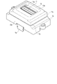
- the sensor module 63 includes a pressure sensor portion 71, a sensor base 72 that holds the pressure sensor portion 71, an opening 73 a that covers the sensor base 72 and faces the pressure sensor portion 71. And a soft part 74 provided in the opening 73a of the sensor head cover 73.
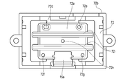
- FIG. 17 is a perspective view showing a partial configuration of the sensor module 63
- FIG. 18 is a plan view of the sensor module 63 as viewed from the other side.
- the sensor module 63 is disposed in the movable case 61 and is held by the movable case 61 so as to be movable within a predetermined movement range along the direction in which the top wall of the movable case 61 and the opening are opposed. That is, the sensor module 63 is held movably in the movable case 61 and its movement is restricted by a restriction means such as a stopper when the sensor module 63 is moved to a position protruding beyond a certain amount from the opening of the movable case 61.
- the pressure sensor unit 71 includes a flexible substrate 71a, a substrate 71b mounted on the flexible substrate 71a, and a plurality of pressure sensitive elements 71c mounted on the substrate 71b.
- the pressure sensor unit 71 is mounted on one main surface of the sensor base 72, and transmits the pressure value measured by the plurality of pressure sensitive elements 71c to the control board 15 via the cable 15a.
- the flexible substrate 71a is formed in a rectangular plate shape, and is bonded onto the sensor base 72 via an adhesive sheet 71e.
- the flexible substrate 71a and the adhesive sheet 71e are formed with openings 71f and cutouts 71g at positions overlapping with later-described flow holes 72d, 72e, 72f, 72g of the sensor base 72, and block the flow holes 72d, 72e, 72f, 72g. It is configured in no shape.
- a predetermined circuit pattern is formed on one main surface of the flexible substrate 71a, and a substrate 71b is mounted.
- the flexible board 71a is connected to the cable 15a, and is electrically connected to the control board 15 via the cable 15a.
- the substrate 71b is formed in a rectangular plate shape and holds a plurality of pressure sensitive elements 71c.
- the substrate 71b and the plurality of pressure sensitive elements 71c constitute a sensor chip.
- a plurality of pressure sensitive elements 71c are arranged in one direction to constitute a pressure sensitive element row 71d.
- the plurality of pressure sensitive elements 71c are arranged in one direction along the width direction of the wrist 100 at the time of wearing, for example.
- One or more pressure-sensitive element rows 71d are provided.
- the plurality of pressure sensitive element rows 71d are arranged at predetermined intervals in a direction orthogonal to the direction in which the plurality of pressure sensitive elements 71c are arranged.
- two pressure-sensitive element rows 71d are arranged.
- the pressure sensitive element 71c is electrically connected to a circuit on the flexible substrate 71a.
- the sensor base 72 is made of, for example, synthetic resin, and includes a support wall portion 72a that holds the pressure sensor portion 71, and a peripheral wall portion 72b that is erected from the outer peripheral edge of the support wall portion 72a on the back surface side opposite to the living body. , And a recess 72c is formed on the back side of the support wall 72a.
- the sensor base 72 holds the pressure sensor unit 71 and the cable 15 a connected to the pressure sensor unit 71.
- the support wall portion 72a is formed in a rectangular plate shape having a predetermined thickness.
- the support wall portion 72a holds the pressure sensor portion 71 in a region facing the opening 73a of the sensor head cover 73 on the surface side that is the living body side.
- a stepped portion 72j whose center is convex is formed on the outer peripheral edge of the support wall 72a.
- the support wall portion 72a includes a plurality of through holes penetrating in the thickness direction. Specifically, a first hole 72d and a second hole 72e serving as an inflow port are arranged on one side portion across the pressure sensor unit 71, and a third hole 72f serving as an outflow port is disposed on the other side portion. A fourth hole 72g is formed. That is, the flow holes 72d, 72e, 72f, 72g are arranged on both sides with the pressure sensitive element row 71d interposed therebetween.
- a first hole 72d is arranged at one end in the longitudinal direction of the pressure sensor 71, and a second hole 72e is arranged at the other end.
- a third hole 72f is formed at one end in the longitudinal direction of the pressure sensor portion 71, and a fourth hole 72g is formed at the other end.
- These flow holes 72d to 72g are unevenly arranged around the area where the pressure sensor unit 71 is disposed.
- the flow holes 72d to 72g have different sizes or shapes, and have different channel resistances.
- the plurality of flow holes 72d to 72g are non-uniformly arranged, and for example, the distance from the pressure sensitive element 71c arranged at the center of the pressure sensor unit 71 is different. That is, the flow holes 72d to 72g are asymmetric with respect to the pressure-sensitive element row 71d of the pressure sensor unit 71.
- the soft resin material forming the soft portion 74 to be described later is transferred from the other main surface side to the one main surface side. It is configured to be able to flow into the opening 73a.
- At least one of the plurality of flow holes 72d to 72g serves as an inlet for the soft resin material, and the other hole serves as an outlet for discharging excess resin material and air when the soft resin material is filled. It becomes.
- the first hole 72d and the second hole 72e are inflow holes
- the other two third holes 72f and fourth holes 72g are outflow holes.
- the first hole 72d has an opening dimension in the longitudinal direction of the pressure sensor unit 71 that is longer than an opening dimension in the width direction of the pressure sensor unit 71, and is formed in an oval shape that is long in the first direction.
- the opening area of the first hole is configured to be larger than the other three holes 72e, 72f, 72g. Further, the inner wall of the first hole 72d is formed in a taper shape in which the diameter on the back side is enlarged.
- the second hole 72e has a circular shape.
- the opening area of the second hole 72e is smaller than that of the first hole 72d.
- the inner wall of the second hole 72e is formed in a taper shape in which the diameter on the back side is enlarged.
- the second hole 72e has the same flow path diameter as the third hole 72f and the fourth hole 72g, and is configured to be tapered, so that the opening area on the back side is larger than that of the third hole 72f and the fourth hole 72g. It is configured.
- the third hole 72f and the fourth hole 72g are formed in a circular shape having a smaller opening diameter than the first hole 72d and the second hole 72e.
- the third hole 72f and the fourth hole 72g are formed constant in the axial direction of the hole, that is, in the thickness direction of the support wall 72a.
- the third hole 72f and the fourth hole 72g are spaced apart, and the distance between the third hole 72f and the fourth hole 72g in the first direction is set larger than the distance between the first hole 72d and the second hole 72e. ing.
- the sum of the opening areas of the first hole 72d and the second hole 72e arranged on one side of the pressure sensor unit 71 is equal to that of the holes 72f and 72g arranged on the other side of the pressure sensor unit 71. It is larger than the total opening area.
- the fifth hole 72h is a circular hole that is disposed in the center of the support wall 72a where the pressure sensor 71 is disposed and penetrates in the thickness direction.
- the peripheral wall portion 72b is erected from the outer periphery of the support wall portion 72a on the side opposite to the living body, and the support wall portion 72a and the peripheral wall portion 72b form a recess 72c that opens on the back side of the sensor base 72. Irregularities along the first direction are formed on the back surface of the support wall portion 72a. Specifically, the protrusions 72i extending in the first direction along the longitudinal direction of the pressure sensor unit 71 are respectively provided on the back surfaces of the regions on both sides of the region where the pressure sensor unit 71 of the support wall 72a is formed. Is formed.
- the sensor head cover 73 is made of, for example, a synthetic resin and has a rectangular shape with a central portion protruding toward the living body.
- the sensor head cover 73 is integrally provided with a convex part 73b having an opening 73a and a frame part 73c provided on the periphery of the convex part 73b.
- the convex portion 73b is configured in a plate shape having a rectangular opening 73a. At least the central part of the main surface that contacts the living body on one side of the convex part 73b is configured to be flat.
- the main surface on the other side of the convex portion 73b is formed in a tapered shape having an inclined surface 73g inclined toward one side toward the central opening 73a.
- the inner wall of the corner portion 73h which is the boundary between the convex portion 73b and the frame portion 73c, is formed with a curved surface with R formed by surface processing.
- the sensor head cover 73 has no corner from the inner wall of the frame portion 73c disposed on the outer periphery to the opening 73a through the curved corner portion 73h, and the gap 79 between the sensor base 72 and the sensor base 72 is formed.
- the fluid resistance is small.
- the frame portion 73c is erected on the sensor base 72 side from the peripheral edge of the convex portion 73b, and engages with a stepped portion 72j on the outer peripheral edge of the support wall portion 72a of the sensor base 72.
- At least a part of the facing surfaces of the sensor head cover 73 and the sensor base 72 is spaced apart, and a gap portion in which the pressure sensor portion 71 and the soft portion 74 are disposed between the inner surface of the sensor head cover 73 and the outer surface of the sensor base 72. 79 is formed.
- a gap 79 is formed between each of the surfaces by gaps formed.
- the gap portion 79 communicates with the plurality of flow holes 72d to 72g of the sensor base 72 through the cutout portion 71g of the flexible substrate 71a and the opening 71f of the adhesive sheet 71e. That is, the gap 79 forms a flow path from the plurality of flow holes 72d to 72g to the opening 73a.
- the soft portion 74 is configured by filling the gap 79 with a soft resin material up to a predetermined height position that covers at least the pressure sensitive element 71c.
- the soft portion 74 is made of a relatively soft resin material such as silicone resin.
- the soft portion 74 is provided in the opening 73 a of the sensor head cover 73 and covers the pressure sensor portion 71 to protect the pressure sensitive element 71 c.
- the soft part 74 is molded by, for example, injecting a soft resin material into the opening 73a.
- the end surface 74 a of the soft part 74 is configured to be flush with the end surface of the sensor head cover 73.
- the soft part 74 may be formed of a material that comes into contact with the wrist 100 and is capable of detecting the pressure of the radial artery 110 with the pressure-sensitive element 71c. Can be set as appropriate.
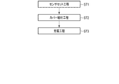
- the manufacturing method of the blood pressure measurement device and the sensor module includes a sensor setting step (step ST1) for setting the pressure sensor unit 71 on the sensor base 72, and a cover assembly step (step ST2) for assembling the sensor head cover 73 to the sensor base 72. And a filling step (step ST3) for supplying a soft resin in a state in which the opening 73a is closed with a facing member.
- the pressure sensor unit 71 is set on the sensor base 72 via the adhesive sheet 71e. Specifically, first, the plurality of pressure sensitive elements 71a are mounted on the substrate 71b. Next, the substrate 71b on which the plurality of pressure sensitive elements 71a are mounted is mounted on the flexible substrate 71a. Thereby, the pressure sensor unit 71 is completed. Next, the pressure sensor unit 71 is fixed on the sensor base 72 via the adhesive sheet 71e.
- the sensor head cover 73 is placed on the sensor base 72 as a cover assembly process (step ST2).
- the pressure sensor unit 71 is disposed in an area corresponding to the opening 73 a of the sensor head cover 73.
- a gap 79 is formed between the sensor base 72 and the sensor head cover 73.
- the gap 79 is a flow path from the opening 73a to the recess 71c on the back side of the sensor base 72 through the openings 71f and notches 71g of the flexible substrate 71a and the adhesive sheet 71e and the flow holes 72d to 72g of the sensor base 72.
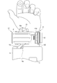
- step ST3 As a filling step (step ST3), first, the sensor base 72 and the sensor head cover 73 are assembled, and the sensor head cover 73 side is disposed so that the sensor head cover 73 faces downward, and an opposing plate 81 (opposing member) having a smooth surface 81a. Are arranged opposite to each other to close the opening 73a. In this state, the nozzle 82 for discharging the soft resin material is inserted into the first hole 72d and the second hole 72e, and the soft resin material is supplied from the first hole 72d and the second hole 72e, respectively.
- the soft resin material flows into the gap 79 from the first hole 72d and is filled up to a predetermined height position that covers the pressure sensor 71, so that the soft resin material is disposed in the opening 73a.
- the other holes 72f and 72g serve as outlets through which air and excess resin material are discharged.
- the flow direction is defined so that the resin flows from the one hole 72d, 72e serving as the inflow port toward the other hole 72f, 72g. It is possible to avoid the occurrence of a weld line in the sensing area where the central pressure sensor unit 71 is arranged. That is, for example, when the resin material flows from the holes on both sides toward the center, the resin material that has flowed in from both sides is joined at a place where the center sensing is affected, so that a weld line is easily formed. If there is a weld line in the soft part of the sensing part (sensitive part), the transmission of pressure is slightly different, so the effect on sensing is greater than in a uniform state where there is no weld line.
- first hole 72d and the second hole 72e have a larger opening area than the third hole 72f and the fourth hole 72g, and the first hole 72d is tapered so that the filling process can be performed smoothly. It can be carried out.
- the soft portion 74 is formed by solidifying the soft resin material filled in the gap 79 including the opening 73a by, for example, cooling treatment or heat treatment according to the type of the soft resin material.
- the sensor base 72, the support plate 77, the circuit board 78, and the sensor head cover 73 are bonded and fixed to each other by the soft portion 74.
- the counter plate 81 is removed at a predetermined timing.
- the counter plate 81 may be removed, and then the soft portion 74 may be further subjected to a surface treatment.
- the sensor module 63 is completed.
- the movable base 64 is held in the movable case 61 so as to be movable along one direction approaching and separating from the wrist 100 in a state where the blood pressure measurement device 1 is attached to the wrist 100.
- the movable base 64 is configured to be movable along a plurality of columnar members provided in the movable case 61.
- the movable base 64 holds the sensor base 72 so that the sensor base 72 can be moved in one direction with respect to the movable case 61 by fixing the end on the wrist 100 side to the sensor base 72.
- the adjusting means 53 is configured to be able to adjust the position of the sensor unit 52 with respect to the case 51 in the circumferential direction of the wrist 100, as shown in FIG.
- the adjustment means 53 has an adjustment knob 53a that is located on the outer surface of the case 51 and that is partly fixed to the fixed portion 61b of the movable case 61 via the third hole 51e.
- the adjustment means 53 includes a scale 53b provided adjacent to the third hole 51e of the case 51, and an instruction part 53c provided on the adjustment knob 53a and pointing to the scale 53b.
- the adjustment knob 53 a is connected to the sensor unit 52 by being fixed to the movable case 61.
- the adjustment knob 53a is configured to be able to move the sensor unit 52. That is, the adjustment means 53 moves the sensor unit 52 along the second groove 51f2 by moving the adjustment knob 53a in the longitudinal direction of the third hole 51e, and adjusts the position with respect to the case 51. It is an adjustment mechanism.
- the scale 53b and the instruction unit 53c are display units that display the position of the adjustment knob 53a, that is, the position of the sensor unit 52 connected to the adjustment knob 53a in a visible manner.
- the fixing tool 43 includes, for example, one or a plurality of band-shaped bands and a fixing member such as a hook-and-loop fastener that wraps the band around the wrist 100 and fixes the attachment part 41 and the sensing body 42 to the wrist 100.
- the fixing tool 43 may be comprised by the 1st belt called the parent which has a buckle, and the 2nd belt called the sword tip fixed to a buckle.
- the fixing tool 43 may further have a configuration for fixing the case 51 to the attachment portion 41 by being wound around the case 51.
- the repulsive force when the sensor module 63 presses the wrist 100 due to the expansion of the air bag 62 is applied to the movable case 61, and the adjustment knob 53a directly or from the movable case 61 by the movable case 61. It may be possible to prevent the case 51 from being indirectly pressed via the movement of the case 51 in a direction away from the attachment portion 41.
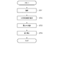
- FIG. 23 is a flowchart showing an example of blood pressure measurement using the blood pressure measurement device 1, and shows both the user operation and the operation of the control unit 33.
- 24 to 26 are explanatory diagrams illustrating an example of blood pressure measurement using the blood pressure measurement device 1.
- the user searches for the position of the radial artery 110 on the wrist 100 by palpation (step ST11).
- the skin on the radial artery 110 may be marked by drawing a line with a pen.
- the user moves the sensing body 42 of the sensor device 5 away from the attachment unit 41.
- the user operates the engagement portion 51b to release the fixing of the case 51 and the base portion 41a, and rotates the sensing body 42 around the rotation shaft 51a in a direction away from the attachment portion 41.
- the user wears the apparatus main body 4 and the sensor apparatus 5 (step ST12).
- the user passes the wrist 100 through the body fixture 16 of the device body 4 and the fixture 43 of the sensor device 5, and places the device body 4 and the sensor device 5 at predetermined positions on the wrist 100.
- the main body fixing tool 16 of the apparatus main body 4 is tightened to fix the apparatus main body 4 to the wrist 100.
- the body fixing tool 16 of the apparatus main body 4 is configured to have a cuff, the skin of the wrist 100 is not sandwiched between the body fixing tool 16 (cuff) and the body fixing tool 16 (cuff) is Check for looseness.
- the position of the sensor device 5 is adjusted so that the opening 41 b of the attach portion 41 of the sensor device 5 is located at the radial artery 110 of the wrist 100. Further, the user fixes the sensor device 5 to the wrist 100 by tightening the fixture 43 of the sensor device 5 while maintaining the radial artery 110 positioned in the opening 41b.
- the user palpates the wrist 100 from the opening 41b of the attach unit 41 (step ST13), and confirms again that the radial artery 110 is located in the opening 41b.
- the user rotates the sensing main body 42 in the direction approaching the attachment part 41 and fixes the sensing main body 42 to the attachment part 41 by the engaging part 51 b.
- the position of the sensing body 42 is adjusted by operating the adjustment knob 53a.
- the control unit 33 measures the blood pressure based on the blood pressure measurement command (step ST14). At this time, the control unit 33 drives and controls the pump 14 to inflate the air bag 62, so that the sensor module 63 is gradually housed in the movable case 61 as shown in FIGS. 9 and FIG. 12, the sensor head cover 73 and the soft part 74 of the sensor module 63 press the area where the radial artery 110 of the wrist 100 exists. When the sensor head cover 73 and the soft part 74 press against the region of the wrist 100, the radial artery 110 is pressed with an appropriate pressure as shown in FIG. In this state, each pressure sensitive element 71c of the pressure sensor unit 71 measures a pressure pulse wave.
- the control unit 33 obtains the blood pressure by the tonometry method from the pressure pulse wave of the radial artery 110 detected by the pressure sensor unit 71. Prior to blood pressure measurement, the control unit 33 may perform blood pressure measurement for calibration based on the program data stored in the storage unit 32, and the mounting state and pressure of the device main body 4 and the sensor device 5 may be measured. You may determine whether the position of the sensor part 71 is correct.
- the sensor module 63 includes the sensor base 72 having the support wall portion 72a having the holes 72d to 72g.
- the soft portion 74 can be formed by filling the soft resin. Therefore, for example, by filling the soft resin from the other main surface side of the sensor base 72 with the opening 73a of the sensor head cover 73 facing the smooth surface 81a, the process of forming the soft portion 74 is facilitated.
- the flow of the soft resin can be defined by injecting the soft resin from any of the unevenly arranged holes, and the soft portion 74 can be reliably filled on the surface of the pressure sensor portion 71, and the smoothness High surface can be formed.
- a process can be simplified and a surface with high smoothness can be formed as compared with a process of filling a soft resin from the opening side of one main surface and then pressing a smooth surface against the opening. Further, the load on the pressure sensor array can be reduced, and high sensor accuracy can be ensured.
- the flow holes 72d to 72g can be unevenly arranged and shaped to define the flow direction. That is, for example, by making the flow of the soft resin in one direction, it is possible to prevent the soft resin material from being biased, and it is possible to prevent a weld line from being generated on the sensor 71a which causes a decrease in sensing accuracy or damage.
- the flow direction of the soft resin can be obtained by using the flow hole on one side as an inflow port and the flow hole on the other side as an outflow port for excess filler or air. And the filling process can be accelerated.
- the sensor module 63 can promote the inflow of the resin material by forming the gap portion 79 having the tapered inclined surface 73g inclined toward the central region where the pressure sensor portion 71 is disposed. At the same time, defoaming near the sensor surface can be promoted. Since the gap 79 has a structure with no corner on the inner wall and low resistance, the inflow of the resin material can be promoted, and filling can be performed only by the weight of the resin without applying pressure or temperature.
- the resin material is injected into an appropriate place, and at the same time the cooling process or heat treatment is performed to cure the soft resin, thereby shortening the assembly time. In such a case, a weld line is generated more. Since it becomes easy, the structure of this embodiment becomes useful.
- the present invention is not limited to the above embodiment.
- the configuration in which the two circulation holes 72d and 72e arranged on one side are used as the injection port as the filling process has been described, but the present invention is not limited to this.
- one inflow port may be provided and a soft resin material may be supplied from one hole 72d.
- the flow direction is defined in one direction, and a weld line is unlikely to occur.
- three or more nozzles 82 may be used to inject the soft resin material into three or more circulation holes.
- the blood pressure measurement device 1 has been described as having a configuration in which the device main body 4 and the sensor device 5 are provided separately, but is not limited thereto.
- the device body 4 and the sensor device 5 may be configured integrally.
- the blood pressure measurement device 1 having such a configuration may be configured such that the operation unit 12, the display unit 13, the pump 14, and the control board 15 used in the device body 4 are provided in the case 51 of the sensing body 42.
- the blood pressure measurement device 1 is configured to move in the direction in which the sensing body 42 moves away from and the direction in which the sensing body 42 moves toward the attachment unit 41, and the sensing body 42 rotates with respect to the attachment unit 41 around one axis.
- the present invention is not limited to this.
- the blood pressure measurement device 1 has a configuration in which the attachment unit 41 and the sensing body 42 are separated as a configuration in which the sensing body 42 moves in a direction in which the sensing body 42 moves away from and a direction in which the sensing body 42 approaches. Also good.
- the engagement portions 51b are provided at a plurality of locations of the case 51 of the sensing body 42, and the sensing body 42 is engaged with the attachment portion 41 at a plurality of positions. do it.
- the configuration in which the sensing body 42 rotates with respect to the attachment unit 41 around one axis is not limited to the above example. That is, in the above-described example, the sensing main body 42 has been described as being configured to rotate about one axis extending in a direction orthogonal to the circumferential direction of the wrist 100 with respect to the attachment unit 41, but is not limited thereto. In other words, the sensing body 42 may be configured to rotate about one axis extending in the tangential direction of the wrist 100 with respect to the attachment unit 41.
- the blood pressure measurement device 1 has been described with respect to the configuration in which the pressure of the radial artery 110 is measured and the blood pressure is obtained by the tonometry method. There may be.
- the blood pressure measurement device 1 may be configured to obtain blood pressure by a method other than the tonometry method.
- the example which mentioned above demonstrated the structure which is the shape which can palpate the wrist 100 for the opening part 41b of the attachment part 41, it is not limited to this.
- the opening 41 b of the attachment unit 41 may have a shape that allows the sensor unit 52 to contact the wrist 100 beyond the opening 41 b in a range in which the position is adjusted by the adjusting unit 53.
- the present invention is not limited to a device that measures blood pressure, and can also be used in a device that uses other measurement methods such as a device that measures pulse waves.
- the sensor unit 52 has been described with the configuration in which the sensor base 72 of the sensor module 63 is held by the movable base 64 that can move in the movable case 61, but the present invention is not limited to this.
- the movable base 64 may be configured integrally with the sensor base 72 of the sensor module 63.
- flow holes (first hole, second hole, third hole, fourth hole, fifth hole), 72i ... ridge, 72j ... a step, 73 ... sensor head cover, 73a ... opening, 73b ... convex portion, 73c ... Frame part, 73g ... inclined surface, 73h ... Corner part, 74 ... soft part, 74a ... end face, 81 ... counter plate, 81a ... smooth surface, 82 ... Nozzle, 100 ... wrist, 110 ... radial artery, 111 ... ribs, 112 ... Ulna artery, 113 ... Ulna, 114 ... Tendon.
Landscapes
- Health & Medical Sciences (AREA)
- Life Sciences & Earth Sciences (AREA)
- Heart & Thoracic Surgery (AREA)
- Medical Informatics (AREA)
- Physics & Mathematics (AREA)
- Veterinary Medicine (AREA)
- Biophysics (AREA)
- Pathology (AREA)
- Engineering & Computer Science (AREA)
- Biomedical Technology (AREA)
- Public Health (AREA)
- General Health & Medical Sciences (AREA)
- Molecular Biology (AREA)
- Surgery (AREA)
- Animal Behavior & Ethology (AREA)
- Cardiology (AREA)
- Vascular Medicine (AREA)
- Physiology (AREA)
- Ophthalmology & Optometry (AREA)
- Measuring Pulse, Heart Rate, Blood Pressure Or Blood Flow (AREA)
Priority Applications (3)
| Application Number | Priority Date | Filing Date | Title |
|---|---|---|---|
| DE112019001923.6T DE112019001923T5 (de) | 2018-05-24 | 2019-05-21 | Sensormodul, verfahren zur herstellung eines sensormoduls und blutdruckmessvorrichtung |
| CN201980028735.6A CN112153937B (zh) | 2018-05-24 | 2019-05-21 | 传感器模块、传感器模块的制造方法以及血压测定装置 |
| US16/950,467 US11883137B2 (en) | 2018-05-24 | 2020-11-17 | Sensor module, method for manufacturing sensor module, and blood pressure measurement device |
Applications Claiming Priority (2)
| Application Number | Priority Date | Filing Date | Title |
|---|---|---|---|
| JP2018-099715 | 2018-05-24 | ||
| JP2018099715A JP7091831B2 (ja) | 2018-05-24 | 2018-05-24 | センサモジュール、センサモジュールの製造方法、及び血圧測定装置 |
Related Child Applications (1)
| Application Number | Title | Priority Date | Filing Date |
|---|---|---|---|
| US16/950,467 Continuation US11883137B2 (en) | 2018-05-24 | 2020-11-17 | Sensor module, method for manufacturing sensor module, and blood pressure measurement device |
Publications (1)
| Publication Number | Publication Date |
|---|---|
| WO2019225582A1 true WO2019225582A1 (ja) | 2019-11-28 |
Family
ID=68617025
Family Applications (1)
| Application Number | Title | Priority Date | Filing Date |
|---|---|---|---|
| PCT/JP2019/020049 Ceased WO2019225582A1 (ja) | 2018-05-24 | 2019-05-21 | センサモジュール、センサモジュールの製造方法、及び血圧測定装置 |
Country Status (5)
| Country | Link |
|---|---|
| US (1) | US11883137B2 (https=) |
| JP (1) | JP7091831B2 (https=) |
| CN (1) | CN112153937B (https=) |
| DE (1) | DE112019001923T5 (https=) |
| WO (1) | WO2019225582A1 (https=) |
Families Citing this family (1)
| Publication number | Priority date | Publication date | Assignee | Title |
|---|---|---|---|---|
| TWI872185B (zh) | 2020-01-10 | 2025-02-11 | 美商菲歐普提斯公司 | 醫療裝置及用於製造醫療裝置的方法 |
Citations (4)
| Publication number | Priority date | Publication date | Assignee | Title |
|---|---|---|---|---|
| JP2010233883A (ja) * | 2009-03-31 | 2010-10-21 | Nippon Zeon Co Ltd | カテーテル |
| JP2011200267A (ja) * | 2010-03-24 | 2011-10-13 | Seiko Epson Corp | センサー装置及び生体情報測定装置 |
| JP2015144628A (ja) * | 2014-01-31 | 2015-08-13 | オムロンヘルスケア株式会社 | 脈波検出装置 |
| JP2016072589A (ja) * | 2014-09-29 | 2016-05-09 | 新科實業有限公司SAE Magnetics(H.K.)Ltd. | 薄膜圧電体素子およびその製造方法並びにそれを有するヘッドジンバルアセンブリ、ハードディスク装置、インクジェットヘッド、可変焦点レンズおよびセンサ |
Family Cites Families (7)
| Publication number | Priority date | Publication date | Assignee | Title |
|---|---|---|---|---|
| JP2613622B2 (ja) | 1988-05-16 | 1997-05-28 | コーリン電子株式会社 | 脈波検出装置 |
| JP3818220B2 (ja) * | 2002-06-03 | 2006-09-06 | オムロンヘルスケア株式会社 | 手首式血圧計用カフ |
| US7314450B2 (en) * | 2003-08-29 | 2008-01-01 | Casio Computer Co., Ltd. | Wearable heartbeat measuring device, system and method |
| JP2006218178A (ja) * | 2005-02-14 | 2006-08-24 | Omron Healthcare Co Ltd | 血圧計用カフおよび血圧計 |
| JP5007193B2 (ja) * | 2007-10-03 | 2012-08-22 | 日本精密測器株式会社 | 血圧計 |
| JP6051732B2 (ja) * | 2012-09-25 | 2016-12-27 | オムロンヘルスケア株式会社 | 血圧情報測定装置用カフ及び血圧情報測定装置 |
| JP6287894B2 (ja) * | 2015-02-27 | 2018-03-07 | オムロンヘルスケア株式会社 | 血圧測定用カフおよび血圧計 |
-
2018
- 2018-05-24 JP JP2018099715A patent/JP7091831B2/ja active Active
-
2019
- 2019-05-21 WO PCT/JP2019/020049 patent/WO2019225582A1/ja not_active Ceased
- 2019-05-21 DE DE112019001923.6T patent/DE112019001923T5/de active Pending
- 2019-05-21 CN CN201980028735.6A patent/CN112153937B/zh active Active
-
2020
- 2020-11-17 US US16/950,467 patent/US11883137B2/en active Active
Patent Citations (4)
| Publication number | Priority date | Publication date | Assignee | Title |
|---|---|---|---|---|
| JP2010233883A (ja) * | 2009-03-31 | 2010-10-21 | Nippon Zeon Co Ltd | カテーテル |
| JP2011200267A (ja) * | 2010-03-24 | 2011-10-13 | Seiko Epson Corp | センサー装置及び生体情報測定装置 |
| JP2015144628A (ja) * | 2014-01-31 | 2015-08-13 | オムロンヘルスケア株式会社 | 脈波検出装置 |
| JP2016072589A (ja) * | 2014-09-29 | 2016-05-09 | 新科實業有限公司SAE Magnetics(H.K.)Ltd. | 薄膜圧電体素子およびその製造方法並びにそれを有するヘッドジンバルアセンブリ、ハードディスク装置、インクジェットヘッド、可変焦点レンズおよびセンサ |
Also Published As
| Publication number | Publication date |
|---|---|
| CN112153937A (zh) | 2020-12-29 |
| DE112019001923T5 (de) | 2020-12-24 |
| JP2019201978A (ja) | 2019-11-28 |
| CN112153937B (zh) | 2023-08-11 |
| JP7091831B2 (ja) | 2022-06-28 |
| US20210068679A1 (en) | 2021-03-11 |
| US11883137B2 (en) | 2024-01-30 |
Similar Documents
| Publication | Publication Date | Title |
|---|---|---|
| JP7106986B2 (ja) | センサモジュール、血圧測定装置 | |
| US11653842B2 (en) | Blood pressure measuring device | |
| US11647912B2 (en) | Blood pressure measuring device | |
| JP2019118407A (ja) | 血圧測定装置 | |
| US11529063B2 (en) | Blood pressure measuring device | |
| JP7087673B2 (ja) | センサモジュール及び血圧測定装置 | |
| WO2019225582A1 (ja) | センサモジュール、センサモジュールの製造方法、及び血圧測定装置 | |
| JP7077776B2 (ja) | 血圧測定装置 | |
| JP7091832B2 (ja) | センサモジュール、センサモジュールの製造方法、及び血圧測定装置 | |
| WO2019225586A1 (ja) | 血圧測定装置 | |
| WO2019225585A1 (ja) | 血圧測定装置 | |
| US11653879B2 (en) | Blood pressure measuring device | |
| US20200323447A1 (en) | Blood pressure measuring device |
Legal Events
| Date | Code | Title | Description |
|---|---|---|---|
| 121 | Ep: the epo has been informed by wipo that ep was designated in this application |
Ref document number: 19807878 Country of ref document: EP Kind code of ref document: A1 |
|
| 122 | Ep: pct application non-entry in european phase |
Ref document number: 19807878 Country of ref document: EP Kind code of ref document: A1 |