WO2019225293A1 - Structure d'absorption sonore - Google Patents
Structure d'absorption sonore Download PDFInfo
- Publication number
- WO2019225293A1 WO2019225293A1 PCT/JP2019/017775 JP2019017775W WO2019225293A1 WO 2019225293 A1 WO2019225293 A1 WO 2019225293A1 JP 2019017775 W JP2019017775 W JP 2019017775W WO 2019225293 A1 WO2019225293 A1 WO 2019225293A1
- Authority
- WO
- WIPO (PCT)
- Prior art keywords
- hole
- perforated plate
- fine perforated
- absorbing structure
- space
- Prior art date
Links
Images
Classifications
-
- B—PERFORMING OPERATIONS; TRANSPORTING
- B60—VEHICLES IN GENERAL
- B60H—ARRANGEMENTS OF HEATING, COOLING, VENTILATING OR OTHER AIR-TREATING DEVICES SPECIALLY ADAPTED FOR PASSENGER OR GOODS SPACES OF VEHICLES
- B60H1/00—Heating, cooling or ventilating [HVAC] devices
-
- G—PHYSICS
- G10—MUSICAL INSTRUMENTS; ACOUSTICS
- G10K—SOUND-PRODUCING DEVICES; METHODS OR DEVICES FOR PROTECTING AGAINST, OR FOR DAMPING, NOISE OR OTHER ACOUSTIC WAVES IN GENERAL; ACOUSTICS NOT OTHERWISE PROVIDED FOR
- G10K11/00—Methods or devices for transmitting, conducting or directing sound in general; Methods or devices for protecting against, or for damping, noise or other acoustic waves in general
- G10K11/16—Methods or devices for protecting against, or for damping, noise or other acoustic waves in general
- G10K11/172—Methods or devices for protecting against, or for damping, noise or other acoustic waves in general using resonance effects
Definitions
- the present disclosure relates to a sound absorbing structure that absorbs sound using a fine perforated plate.
- a plurality of fine through holes are formed in a fine perforated plate used in this type of sound absorbing structure.
- a fine perforated plate is arranged through an air layer (in other words, an intervening space) with respect to the wall and ceiling of the sound field.
- Such an arrangement constitutes a spring-mass system in which the air in the through hole of the fine perforated plate is used as a mass and the air layer between the wall or ceiling and the fine perforated plate is used as a spring.
- the air around the through hole vibrates due to the resonance frequency of the spring-mass system, thereby absorbing sound.
- Patent Document 1 discloses a sound absorbing structure as described above.
- a fine through-hole is formed in a glass building component arranged at a distance from a wall. The glass building component is used as a fine perforated plate for absorbing sound.
- Patent Document 1 The sound absorbing structure of Patent Document 1 is not intended to absorb the sound of the circulation space through which the fluid flows (that is, the sound of the flow field). Therefore, for the purpose of sound absorption in the distribution space, for example, if a fine perforated plate similar to the glass building component of Patent Document 1 is arranged so as to face the distribution space without taking any measures, the through hole of the fine perforated plate The fluid flow in the circulation space might be disturbed around And when the fluid flow is disturbed in such a way, noise resulting from it is generated. As a result of detailed studies by the inventors, the above has been found.
- the present disclosure provides a sound absorbing structure capable of obtaining a sound absorption effect in a target frequency band with a fine perforated plate while suppressing the through hole of the fine perforated plate from disturbing the fluid flow in the circulation space.
- the purpose is to provide.
- the sound absorbing structure includes: A sound absorbing structure using a fine perforated plate, A micro perforated plate having one surface facing the flow space through which the fluid flows and the other surface opposite to the one surface, in which a through hole penetrating from one surface to the other surface is formed; An opposing wall facing the other surface of the fine perforated plate through an intervening space; The through hole is formed so that the hole cross-sectional area of the through hole in the cross section orthogonal to the axial direction of the through hole becomes larger toward the other surface side in the axial direction.
- the volume of the through hole of the fine perforated plate is set to a desired size, and the opening area where the through hole opens with respect to the circulation space is compared with the case where the hole cross-sectional area of the through hole is constant. Can be small. Therefore, it is possible to obtain a sound absorption effect in a target frequency band by the fine perforated plate while suppressing the through-hole from disturbing the fluid flow in the circulation space.
- the sound absorbing structure is A sound absorbing structure using a fine perforated plate, A micro perforated plate having one surface facing the flow space through which the fluid flows and the other surface opposite to the one surface, in which a through hole penetrating from one surface to the other surface is formed; An opposing wall facing the other surface of the fine perforated plate through an intervening space;
- the through-hole has one open end on one side,
- the micro-perforated plate has a hole peripheral portion formed so as to surround the one-surface-side open end, The hole periphery has a chamfered shape.
- FIG. 6 is an arrow view in the VI direction of FIG. 5.
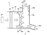
- the sound absorbing structure 10 of this embodiment is a sound absorbing structure using a fine perforated plate, and is applied to the air conditioning unit 2 shown in FIG.
- the air conditioning unit 2 blows conditioned air into the passenger compartment. That is, the air-conditioning unit 2 is a vehicle air-conditioning unit that is installed in the vehicle interior and performs air-conditioning in the vehicle interior.
- the air conditioning unit 2 includes an air conditioning case 21, a blower 23, an evaporator 26, a heater core 27, air mix doors 28 and 29, and a blowout opening door 254. Etc.
- the air conditioning case 21 is formed of a resin having a certain degree of elasticity and excellent in strength.
- the resin forming the air conditioning case 21 include polypropylene.
- the air conditioning case 21 forms an outer shell of the air conditioning unit 2, and an air passage, that is, a ventilation passage 24, through which air blown into the vehicle interior flows is formed inside the air conditioning case 21.
- the air conditioning case 21 has a plurality of blowing openings 251 and 252 for blowing air from the ventilation path 24 to a predetermined area in the passenger compartment on the downstream side of the ventilation path 24 in the air flow direction.
- a blower 23 In the air conditioning case 21, a blower 23, an evaporator 26, a heater core 27, air mix doors 28 and 29, and the like are provided.
- the blower 23 has a fan disposed in the ventilation path 24 and a motor that rotationally drives the fan.
- the blower 23 sucks in air that is inside air or outside air as the fan rotates, and causes the sucked air to flow through the air passage 24.
- the air introduced into the ventilation path 24 by the blower 23 flows through the ventilation path 24 and is blown out from any one of the plurality of blowing openings 251 and 252 into the vehicle interior.
- the air flow in the ventilation path 24 is indicated by white arrows.
- the inside air is the air inside the passenger compartment
- the outside air is the air outside the passenger compartment.
- the blowing opening door 254 is provided in the first blowing opening 251 among the plurality of blowing openings 251 and 252 and adjusts the opening area of the first blowing opening 251.
- the second outlet opening 252 of the plurality of outlet openings 251 and 252 is not provided with an outlet opening door, but the second outlet opening 252 also includes the first outlet opening.
- a blowout opening door may be provided.
- the evaporator 26 is a heat exchanger for cooling the air flowing through the ventilation path 24. Since the evaporator 26 is disposed downstream in the air flow direction with respect to the blower 23, the air blown from the blower 23 flows to the evaporator 26 in the ventilation path 24. The evaporator 26 exchanges heat between the air passing through the evaporator 26 and the refrigerant, thereby cooling the air and evaporating the refrigerant.
- the heater core 27 is a heat exchanger for heating the air flowing through the ventilation path 24.
- the heater core 27 exchanges heat between, for example, engine coolant and air passing through the heater core 27, and heats the air with the heat of the engine coolant. Further, the heater core 27 is disposed on the downstream side in the air flow direction with respect to the evaporator 26.
- the air passage 24 of the air conditioning case 21 includes bypass passages 24a and 24b that are formed in parallel to the heater core 27 and flow air by bypassing the heater core 27.
- Air mix doors 28 and 29 are provided between the evaporator 26 and the heater core 27 in the ventilation path 24 of the air conditioning unit 2.
- the air mix doors 28 and 29 pass between the evaporator 26 and the air volume that flows around the heater core 27 (that is, the air volume that flows through the bypass passages 24 a and 24 b) and the air volume that passes through the evaporator 26 and then passes through the heater core 27. Adjust the percentage.
- the sound absorbing structure 10 of the present embodiment is provided inside the air conditioning case 21 in order to absorb sound generated in the air conditioning case 21.
- the air conditioning case 21 has an installation range Wp in which the sound absorbing structure 10 can be installed, and the sound absorbing structure 10 is provided at any location within the installation range Wp or the entire installation range Wp. ing.
- the installation range Wp of the sound absorbing structure 10 includes the bypass passages 24a and 24b in the ventilation passage 24 and extends from the bypass passages 24a and 24b to the downstream side in the air flow direction.
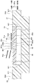
- the installation range Wp is a hatched range in FIG. 2 is a diagram showing the sound absorbing structure 10 assuming that the sound absorbing structure 10 is provided in the II portion of FIG.
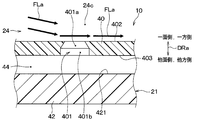
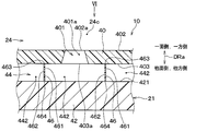
- the sound absorbing structure 10 includes a micro perforated plate 40 in which a plurality of fine through holes 401 are formed, and an opposing wall 42 arranged side by side with respect to the micro perforated plate 40.
- the fine perforated plate 40 of this embodiment is made of resin, for example.
- the facing wall 42 constitutes a part of the air conditioning case 21, it is made of the same resin as the air conditioning case 21.
- the fine perforated plate 40 has a thin plate shape and is fixed to the air conditioning case 21, for example.
- the micro perforated plate 40 is called, for example, MPP (that is, Micro-Perforated Panel).
- the fine perforated plate 40 has one surface 402 and another surface 403 opposite to the one surface 402.
- One surface 402 of the fine perforated plate 40 is a surface provided on one side of the fine perforated plate 40 in the axial direction DRa of the through hole 401.
- the other surface 403 is a surface provided on the other side in the axial direction DRa of the through hole 401 in the fine perforated plate 40.
- the one surface 402 of the fine perforated plate 40 faces the distribution space 24c through which a fluid (specifically, air) flows.
- a fluid specifically, air
- Each of the plurality of through holes 401 penetrates the fine perforated plate 40 from one surface 402 to the other surface 403. Therefore, the axial direction DRa of the through hole 401 is the same as the thickness direction of the fine perforated plate 40.
- the through-hole 401 of this embodiment is a hole of a circular cross section, for example.
- the axial direction DRa of the through hole 401 is also referred to as a hole axial direction DRa.
- each element such as the through hole 401 is displayed in a different size compared to the actual size in order to illustrate each element in an easy-to-understand manner. This is the same in each drawing described later.
- the distribution space 24c of FIG. 2 is included in the ventilation path 24 (see FIG. 1) in the air conditioning case 21 and is fine.
- the perforated plate 40 is provided in the air conditioning case 21.
- the fluid flowing in the circulation space 24 c is air flowing in the ventilation path 24.
- the air flow in the circulation space 24c is represented by an arrow FLa in FIG.
- the facing wall 42 is disposed so as to face the other surface 403 of the fine perforated plate 40 via the intervening air layer 44 (that is, the intervening space 44).
- the facing wall 42 has a facing surface 421 facing the intervening air layer 44, and the facing surface 421 faces the other surface 403 of the fine perforated plate 40.
- the facing surface 421 may or may not be parallel to the other surface 403 of the fine perforated plate 40.
- the hole cross-sectional area Ah of the through hole 401 of the fine perforated plate 40 is not constant in the cross section orthogonal to the hole axial direction DRa. Specifically, the through hole 401 is formed so that the hole cross-sectional area Ah becomes larger toward the other surface 403 side of the hole axial direction DRa.
- the through hole 401 of the fine perforated plate 40 has a cross-sectional area changing portion 401a in which the hole cross-sectional area Ah changes according to the position in the hole axial direction DRa.
- the cross-sectional area changing portion 401a of the present embodiment is a portion where the hole cross-sectional area Ah increases as the position in the hole axial direction DRa is closer to the other surface 403.
- the through hole 401 is formed in the other surface 403 from the position of the portion 402a in which the through hole 401 is formed in the one surface 402 of the fine perforated plate 40 in the hole axial direction DRa. It extends to the position of the part 403a. In short, the cross-sectional area changing portion 401 a reaches the entire length of the through hole 401.
- peripheral edge portion 441 of the intervening air layer 44 is closed by the air conditioning case 21 over the entire circumference.
- the sound absorbing structure 10 is provided with the fine perforated plate 40 and the opposing wall 42 as described above, the air in the through hole 401 of the fine perforated plate 40 is used as a mass, and the air in the intervening air layer 44 is used as a spring.
- a spring-mass system is constructed. Since the air around the through hole 401 vibrates due to the resonance frequency of the spring-mass system, the sound absorbing structure 10 absorbs the sound in the circulation space 24c.
- the air conditioning case 21 of the present embodiment is formed so that the case wall surface of the ventilation path 24 is not uneven due to the fine perforated plate 40 being provided in the air conditioning case 21.
- the ventilation path 24 in the air conditioning case 21 includes a connection space 24d connected to the distribution space 24c.
- the air conditioning case 21 has a connection space case surface 211 facing the connection space 24 d, and the micro perforated plate 40 is disposed so that one surface 402 of the micro perforated plate 40 is continuous with the connection space case surface 211. .
- the through hole 401 of the micro perforated plate 40 is formed such that the hole cross-sectional area Ah increases toward the other surface 403 side of the hole axial direction DRa. ing. Therefore, the opening area of the through-hole 401 with respect to the flow space 24c is set to a desired size while the volume of the through-hole 401 of the fine perforated plate 40 is set as compared with the case where the hole sectional area Ah of the through-hole 401 is constant. And can be made smaller. Therefore, it is possible to obtain a sound absorption effect in a target frequency band by the fine perforated plate 40 while suppressing the through-hole 401 from disturbing the fluid flow in the circulation space 24c. And noise deterioration can be prevented by suppressing the disturbance of the fluid flow in the circulation space 24c.
- the through hole 401 of the fine perforated plate 40 is formed by, for example, molding using a mold or the like, the die can be easily removed from the through hole 401, and therefore the fine perforated plate 40 can be easily manufactured. Is possible.
- the through hole 401 of the fine perforated plate 40 has the cross-sectional area changing portion 401a in which the hole cross-sectional area Ah increases as the position in the hole axial direction DRa is closer to the other surface 403.
- the through hole 401 is formed in the other surface 403 from the position of the portion 402a in which the through hole 401 is formed in the one surface 402 of the fine perforated plate 40 in the hole axial direction DRa. It extends to the position of the part 403a. Therefore, the opening area where the through-hole 401 opens with respect to the flow space 24c can be reduced by a gradual change in the hole cross-sectional area Ah.
- the facing wall 42 of the sound absorbing structure 10 constitutes a part of the air conditioning case 21.
- the distribution space 24 c facing the fine perforated plate 40 of the sound absorbing structure 10 is included in the ventilation path 24 formed in the air conditioning case 21, and the fine perforated plate 40 is provided in the air conditioning case 21. Therefore, before the noise of the air conditioning unit 2 leaks from the air conditioning case 21 to the outside, the noise can be reduced by the sound absorbing structure 10.
- the ventilation path 24 contains the connection space 24d connected to the distribution space 24c, and the air-conditioning case 21 has the connection space case surface 211 which faces the connection space 24d.
- the fine perforated plate 40 is arranged such that one surface 402 of the fine perforated plate 40 is continuous with the connected space case surface 211. Therefore, it is possible to arrange the fine perforated plate 40 so that the fine perforated plate 40 does not easily become an obstacle in the air flow in the ventilation path 24.
- the through hole 401 of the fine perforated plate 40 is formed such that the hole cross-sectional area Ah (see FIG. 2) of the through hole 401 increases toward the other surface 403 side of the hole axial direction DRa.
- the present embodiment is the same as the first embodiment.
- the cross-sectional area changing portion 401a does not reach the entire length of the through-hole 401, and is disposed so as to be biased toward the one surface 402 side of the hole axial direction DRa. That is, in the present embodiment, the through hole 401 of the fine perforated plate 40 has a cross-sectional area changing portion 401a and a cross-sectional area constant portion 401b having a constant hole cross-sectional area Ah regardless of the position in the hole axial direction DRa. Yes.
- the constant cross-sectional area portion 401b is a portion of the through hole 401 that extends in the hole axial direction DRa with a constant hole cross-sectional area Ah.
- the constant cross-sectional area portion 401b is arranged on the other surface 403 side of the hole axial direction DRa with respect to the cross-sectional area changing portion 401a.
- this embodiment is the same as the first embodiment. And in this embodiment, the effect show
- the through hole 401 of the micro perforated plate 40 is formed so that the hole cross-sectional area Ah (see FIG. 2) of the through hole 401 becomes larger toward the other surface 403 side of the hole axial direction DRa. Absent.
- the present embodiment is different from the first embodiment.
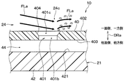
- the through hole 401 of the fine perforated plate 40 has a one-surface-side open end 401c on the one surface 402 side of the hole axial direction DRa.
- the fine perforated plate 40 has a hole peripheral portion 404 formed so as to surround the one surface side open end 401c.
- the hole peripheral portion 404 has a chamfered shape (that is, a chamfered shape). Further, the hole peripheral portion 404 is formed without rising from the one surface 402 of the fine perforated plate 40 in the hole axial direction DRa.
- the chamfered shape of the hole peripheral portion 404 is a chamfered shape with a gradient surface.
- the “chamfered shape” simply defines the shape, and there is no limitation on the method of forming the “chamfered shape”.
- the portion of the through hole 401 excluding the one-surface-side opening end 401c is a constant cross-sectional area portion 401b. Therefore, in the portion of the micro perforated plate 40 where the through hole 401 is formed, the chamfered shape is provided on the one surface 402 side of the hole axial direction DRa, but is provided on the other surface 403 side. Not.
- this embodiment is the same as the first embodiment. And in this embodiment, the effect show
- the hole peripheral portion 404 of the fine perforated plate 40 has a chamfered shape, so that the fluid flow in the circulation space 24 c is disturbed due to the contact with the hole peripheral portion 404. Can be mitigated. Therefore, it is possible to obtain a sound absorption effect in a target frequency band by the fine perforated plate 40 while suppressing the through hole 401 of the fine perforated plate 40 from disturbing the fluid flow in the circulation space 24c. And noise deterioration can be prevented by suppressing the disturbance of the fluid flow in the circulation space 24c.
- the sound absorbing structure 10 of this embodiment includes an intervening space partition wall 46 in addition to the fine perforated plate 40 and the opposing wall 42.
- the intervening space partition wall 46 is provided between the fine perforated plate 40 and the opposing wall 42. That is, the intervening space partition wall 46 is disposed in the intervening air layer 44 (that is, the intervening space 44).
- the intervening space partition 46 partitions the intervening air layer 44 into a plurality of divided spaces 442.
- the intervening space partition wall 46 is provided as a partition wall that separates the plurality of divided spaces 442 from each other.
- the intervening air layer 44 of the present embodiment is composed of a plurality of divided spaces 442 partitioned by intervening space partition walls 46.
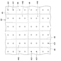
- the intervening space partition 46 is formed so that the shape seen from the hole axis direction DRa is a lattice shape.
- the interstitial space partition 46 is formed so as to extend along the hole axis direction DRa. Specifically, the side wall surfaces 461 and 462 on both sides of the intervening space partition wall 46 are formed so as to extend along the hole axis direction DRa at any location facing the divided space 442. This is because the sound propagation direction in the divided space 442 is aligned along the side wall surfaces 461 and 462.
- the intervening space partition 46 is connected to each of the fine perforated plate 40 and the opposing wall 42. That is, the intervening space partition wall 46 has one end 463 connected to the other surface 403 of the fine perforated plate 40 and the other end 464 connected to the facing surface 421 of the facing wall 42.
- this embodiment is the same as the first embodiment. And in this embodiment, the effect show
- the intervening space partition wall 46 is provided between the fine perforated plate 40 and the facing wall 42 and partitions the intervening air layer 44 into a plurality of divided spaces 442.
- the intervening space partition wall 46 is connected to each of the fine perforated plate 40 and the opposing wall 42. Therefore, it is possible to suppress the micro perforated plate 40 from being deformed by an external force, for example, by the intervening space partition wall 46.
- this embodiment is a modification based on 1st Embodiment, it is also possible to combine this embodiment with the above-mentioned 2nd or 3rd embodiment.
- the fine perforated plate 40 of the sound absorbing structure 10 is made of, for example, resin, but the material of the fine perforated plate 40 is not limited.
- the opposing wall 42 of the sound absorbing structure 10 is made of the same resin as the air conditioning case 21, but if it is molded as a separate member from the air conditioning case 21, May be of different materials. Furthermore, the material of the facing wall 42 is not limited.
- the sound absorbing structure 10 is used in the air conditioning unit 2, but may be used in devices other than the air conditioning unit 2. Absent. Accordingly, the fluid flowing in the circulation space 24c is air flowing in the ventilation path 24, but this is also an example. The fluid flowing in the circulation space 24c may be a fluid other than air.
- the chamfered shape of the hole peripheral portion 404 is a chamfered shape with a gradient surface. There is no problem even if the curved surface is a chamfered surface.
- FIG. 6 shows an example in which two through holes 401 are provided in the fine perforated plate 40 for each divided space 442, but this is an example. Any number of through holes 401 may be provided for each divided space 442. The number of through holes 401 provided for each divided space 442 need not be the same.
- the intervening space partition 46 is formed so that the shape viewed from the hole axis direction DRa is a lattice shape, but this is an example. .
- the shape of the intervening space partition wall 46 as viewed from the hole axial direction DRa is not limited, and the plurality of divided spaces 442 formed by the intervening space partition wall 46 do not need to have the same shape.
- this indication is not limited to the above-mentioned embodiment, It can implement by changing variously.
- a chamfered shape is provided around the opening end 401 c on the one surface side of the through-hole 401 in the fine perforated plate 40, but in embodiments other than the third embodiment, It is also conceivable that a chamfered shape is provided around the one-surface-side opening end 401c.
- a sound absorption structure is provided with a fine perforated board and an opposing wall.
- the micro perforated plate has one surface facing the flow space through which the fluid flows and the other surface opposite to the one surface, and the micro perforated plate has a through hole penetrating from one surface to the other surface. .
- the facing wall faces the other surface of the fine perforated plate via an intervening space.
- the through-hole is formed so that the hole cross-sectional area which the through-hole has in the cross section orthogonal to the axial direction of a through-hole becomes large toward the other surface side of an axial direction.
- the through hole has a one-surface-side opening end on one surface side
- the fine perforated plate has a hole peripheral portion formed so as to surround the one-surface-side opening end.
- the peripheral part of the hole has a chamfered shape.
- the third viewpoint is the same as the second viewpoint.
- the through hole has a cross-sectional area changing portion in which the hole cross-sectional area changes according to the position in the axial direction.
- the cross-sectional area changing portion extends in the axial direction from the position of the portion where the through hole is formed on one surface to the position of the portion where the through hole is formed on the other surface.
- the through hole has a cross-sectional area changing portion in which the hole cross-sectional area increases as the position in the axial direction is closer to the other surface.
- the cross-sectional area changing portion extends in the axial direction from the position of the portion where the through hole is formed on one surface to the position of the portion where the through hole is formed on the other surface. Therefore, the opening area in which the through hole opens with respect to the circulation space can be reduced by a gradual change in the hole cross-sectional area.
- the sound absorbing structure includes a partition wall provided between the fine perforated plate and the facing wall, and the partition partition the intervening space into a plurality of divided spaces. And the partition is connected with each of the fine perforated plate and the opposing wall. Therefore, it is possible to suppress the micro perforated plate from being deformed by an external force, for example, by the partition wall.
- the sound wave propagates along the partition wall in the divided space
- the sound wave propagates in the divided space in the direction along the partition wall regardless of the incident angle of the sound wave entering the through hole from the circulation space. It is possible to align. Thereby, it is possible to suppress the variation in the sound absorption frequency and improve the sound absorption rate of the sound absorption structure.
- the facing wall constitutes a part of the air conditioning case that forms the outer shell of the air conditioning unit that blows the conditioned air into the passenger compartment.
- the circulation space is included in an air passage formed in the air conditioning case, the fluid is air flowing through the air passage, and the fine perforated plate is provided in the air conditioning case. Therefore, before the noise of the air conditioning unit leaks from the air conditioning case to the outside, the noise can be reduced by the sound absorbing structure.
- the air passage includes a connection space connected to the distribution space, and the air conditioning case has a connection space case surface facing the connection space.
- the fine perforated plate is arranged so that one surface is continuous with the connected space case surface. Therefore, it is possible to arrange the fine perforated plate so that the fine perforated plate does not easily become an obstacle in the air flow in the air passage. Therefore, it is possible to suppress the disturbance of the air flow that can occur at the boundary between the location where the fine perforated plate is provided and the location where the fine perforated plate is not provided in the air conditioning case, and to suppress the generation of noise around the fine perforated plate.
Landscapes
- Physics & Mathematics (AREA)
- Engineering & Computer Science (AREA)
- Acoustics & Sound (AREA)
- Multimedia (AREA)
- Thermal Sciences (AREA)
- Mechanical Engineering (AREA)
- Soundproofing, Sound Blocking, And Sound Damping (AREA)
- Air-Conditioning For Vehicles (AREA)
Abstract
L'invention concerne une structure d'absorption sonore qui comprend une plaque finement perforée (40) et une paroi opposée (42). La plaque finement perforée a une première surface (402) faisant face à un espace d'écoulement (24c), à travers lequel un fluide s'écoule, et une autre surface (403) opposée à la première surface. Un trou traversant (401), pénétrant de la première surface à l'autre surface, est formé dans la plaque finement perforée. La paroi opposée fait face à l'autre surface de la plaque finement perforée avec un espace intermédiaire (44) entre celles-ci. En outre, le trou traversant est formé de telle sorte que la zone de section transversale de trou (Ah) du trou traversant dans la section transversale orthogonale à la direction axiale (DRa) du trou traversant devient plus grande vers le côté autre surface dans la direction axiale.
Applications Claiming Priority (2)
| Application Number | Priority Date | Filing Date | Title |
|---|---|---|---|
| JP2018099590A JP2019204010A (ja) | 2018-05-24 | 2018-05-24 | 吸音構造体 |
| JP2018-099590 | 2018-05-24 |
Publications (1)
| Publication Number | Publication Date |
|---|---|
| WO2019225293A1 true WO2019225293A1 (fr) | 2019-11-28 |
Family
ID=68616609
Family Applications (1)
| Application Number | Title | Priority Date | Filing Date |
|---|---|---|---|
| PCT/JP2019/017775 WO2019225293A1 (fr) | 2018-05-24 | 2019-04-25 | Structure d'absorption sonore |
Country Status (2)
| Country | Link |
|---|---|
| JP (1) | JP2019204010A (fr) |
| WO (1) | WO2019225293A1 (fr) |
Cited By (1)
| Publication number | Priority date | Publication date | Assignee | Title |
|---|---|---|---|---|
| EP4270379A1 (fr) * | 2022-04-29 | 2023-11-01 | RTX Corporation | Feuille de face de revêtement acoustique ayant des trous profiles avec des bords allongés |
Citations (5)
| Publication number | Priority date | Publication date | Assignee | Title |
|---|---|---|---|---|
| JP2003015656A (ja) * | 2001-07-04 | 2003-01-17 | National Aerospace Laboratory Of Japan | 微細噴流制御式吸音システム |
| JP2006113323A (ja) * | 2004-10-15 | 2006-04-27 | Kobe Steel Ltd | 多孔板吸音構造体 |
| JP2007024039A (ja) * | 2005-07-13 | 2007-02-01 | United Technol Corp <Utc> | ライナアッセンブリおよびフェイスシートパネルアッセンブリ |
| JP2008231956A (ja) * | 2007-03-16 | 2008-10-02 | Daikyo Nishikawa Kk | 吸音構造体 |
| WO2017090538A1 (fr) * | 2015-11-27 | 2017-06-01 | 株式会社神戸製鋼所 | Plaque insonorisante poreuse |
-
2018
- 2018-05-24 JP JP2018099590A patent/JP2019204010A/ja active Pending
-
2019
- 2019-04-25 WO PCT/JP2019/017775 patent/WO2019225293A1/fr active Application Filing
Patent Citations (5)
| Publication number | Priority date | Publication date | Assignee | Title |
|---|---|---|---|---|
| JP2003015656A (ja) * | 2001-07-04 | 2003-01-17 | National Aerospace Laboratory Of Japan | 微細噴流制御式吸音システム |
| JP2006113323A (ja) * | 2004-10-15 | 2006-04-27 | Kobe Steel Ltd | 多孔板吸音構造体 |
| JP2007024039A (ja) * | 2005-07-13 | 2007-02-01 | United Technol Corp <Utc> | ライナアッセンブリおよびフェイスシートパネルアッセンブリ |
| JP2008231956A (ja) * | 2007-03-16 | 2008-10-02 | Daikyo Nishikawa Kk | 吸音構造体 |
| WO2017090538A1 (fr) * | 2015-11-27 | 2017-06-01 | 株式会社神戸製鋼所 | Plaque insonorisante poreuse |
Cited By (2)
| Publication number | Priority date | Publication date | Assignee | Title |
|---|---|---|---|---|
| EP4270379A1 (fr) * | 2022-04-29 | 2023-11-01 | RTX Corporation | Feuille de face de revêtement acoustique ayant des trous profiles avec des bords allongés |
| US11834997B2 (en) | 2022-04-29 | 2023-12-05 | Rtx Corporation | Face sheet of acoustic liner having streamlined holes with elongated edges |
Also Published As
| Publication number | Publication date |
|---|---|
| JP2019204010A (ja) | 2019-11-28 |
Similar Documents
| Publication | Publication Date | Title |
|---|---|---|
| US8146706B2 (en) | Air duct for vehicle air conditioning and air conditioner for vehicle | |
| WO2016175009A1 (fr) | Soufflante | |
| CN110462222B (zh) | 空调装置 | |
| US20080207111A1 (en) | Ventilation System With Sound Barrier | |
| JP2014163610A (ja) | 熱交換器および空調装置 | |
| US8425284B2 (en) | Heating ventilation and air conditioning case with honeycomb | |
| WO2019225293A1 (fr) | Structure d'absorption sonore | |
| US20100190431A1 (en) | Hvac system including a noise-reducing feature | |
| WO2019176390A1 (fr) | Dispositif de climatisation | |
| WO2016088361A1 (fr) | Unité de climatisation de véhicule | |
| JP2010149741A (ja) | ブロワ装置 | |
| US11164558B2 (en) | Vehicular air conditioning system | |
| WO2019220925A1 (fr) | Unité de climatisation pour véhicule | |
| JP2006335125A (ja) | 空調装置のダクト | |
| JP2008094295A (ja) | 車両用強度部材 | |
| JP2003041528A (ja) | 吸音構造体 | |
| JP2000085339A (ja) | 空調装置 | |
| JP4687099B2 (ja) | 送風装置 | |
| US11446980B2 (en) | HVAC system noise control | |
| WO2023218555A1 (fr) | Climatiseur | |
| WO2021014941A1 (fr) | Dispositif agitateur insonorisant | |
| US11193693B2 (en) | Sound suppression chamber for an HVAC air handling assembly | |
| US11117446B2 (en) | Blower device | |
| WO2023182316A1 (fr) | Dispositif de climatisation | |
| CN114127459A (zh) | 吸音装置 |
Legal Events
| Date | Code | Title | Description |
|---|---|---|---|
| 121 | Ep: the epo has been informed by wipo that ep was designated in this application |
Ref document number: 19807709 Country of ref document: EP Kind code of ref document: A1 |
|
| NENP | Non-entry into the national phase |
Ref country code: DE |
|
| 122 | Ep: pct application non-entry in european phase |
Ref document number: 19807709 Country of ref document: EP Kind code of ref document: A1 |