WO2019225293A1 - Sound absorbing structure - Google Patents
Sound absorbing structure Download PDFInfo
- Publication number
- WO2019225293A1 WO2019225293A1 PCT/JP2019/017775 JP2019017775W WO2019225293A1 WO 2019225293 A1 WO2019225293 A1 WO 2019225293A1 JP 2019017775 W JP2019017775 W JP 2019017775W WO 2019225293 A1 WO2019225293 A1 WO 2019225293A1
- Authority
- WO
- WIPO (PCT)
- Prior art keywords
- hole
- perforated plate
- fine perforated
- absorbing structure
- space
- Prior art date
Links
Images
Classifications
-
- B—PERFORMING OPERATIONS; TRANSPORTING
- B60—VEHICLES IN GENERAL
- B60H—ARRANGEMENTS OF HEATING, COOLING, VENTILATING OR OTHER AIR-TREATING DEVICES SPECIALLY ADAPTED FOR PASSENGER OR GOODS SPACES OF VEHICLES
- B60H1/00—Heating, cooling or ventilating [HVAC] devices
-
- G—PHYSICS
- G10—MUSICAL INSTRUMENTS; ACOUSTICS
- G10K—SOUND-PRODUCING DEVICES; METHODS OR DEVICES FOR PROTECTING AGAINST, OR FOR DAMPING, NOISE OR OTHER ACOUSTIC WAVES IN GENERAL; ACOUSTICS NOT OTHERWISE PROVIDED FOR
- G10K11/00—Methods or devices for transmitting, conducting or directing sound in general; Methods or devices for protecting against, or for damping, noise or other acoustic waves in general
- G10K11/16—Methods or devices for protecting against, or for damping, noise or other acoustic waves in general
- G10K11/172—Methods or devices for protecting against, or for damping, noise or other acoustic waves in general using resonance effects
Definitions
- the present disclosure relates to a sound absorbing structure that absorbs sound using a fine perforated plate.
- a plurality of fine through holes are formed in a fine perforated plate used in this type of sound absorbing structure.
- a fine perforated plate is arranged through an air layer (in other words, an intervening space) with respect to the wall and ceiling of the sound field.
- Such an arrangement constitutes a spring-mass system in which the air in the through hole of the fine perforated plate is used as a mass and the air layer between the wall or ceiling and the fine perforated plate is used as a spring.
- the air around the through hole vibrates due to the resonance frequency of the spring-mass system, thereby absorbing sound.
- Patent Document 1 discloses a sound absorbing structure as described above.
- a fine through-hole is formed in a glass building component arranged at a distance from a wall. The glass building component is used as a fine perforated plate for absorbing sound.
- Patent Document 1 The sound absorbing structure of Patent Document 1 is not intended to absorb the sound of the circulation space through which the fluid flows (that is, the sound of the flow field). Therefore, for the purpose of sound absorption in the distribution space, for example, if a fine perforated plate similar to the glass building component of Patent Document 1 is arranged so as to face the distribution space without taking any measures, the through hole of the fine perforated plate The fluid flow in the circulation space might be disturbed around And when the fluid flow is disturbed in such a way, noise resulting from it is generated. As a result of detailed studies by the inventors, the above has been found.
- the present disclosure provides a sound absorbing structure capable of obtaining a sound absorption effect in a target frequency band with a fine perforated plate while suppressing the through hole of the fine perforated plate from disturbing the fluid flow in the circulation space.
- the purpose is to provide.
- the sound absorbing structure includes: A sound absorbing structure using a fine perforated plate, A micro perforated plate having one surface facing the flow space through which the fluid flows and the other surface opposite to the one surface, in which a through hole penetrating from one surface to the other surface is formed; An opposing wall facing the other surface of the fine perforated plate through an intervening space; The through hole is formed so that the hole cross-sectional area of the through hole in the cross section orthogonal to the axial direction of the through hole becomes larger toward the other surface side in the axial direction.
- the volume of the through hole of the fine perforated plate is set to a desired size, and the opening area where the through hole opens with respect to the circulation space is compared with the case where the hole cross-sectional area of the through hole is constant. Can be small. Therefore, it is possible to obtain a sound absorption effect in a target frequency band by the fine perforated plate while suppressing the through-hole from disturbing the fluid flow in the circulation space.
- the sound absorbing structure is A sound absorbing structure using a fine perforated plate, A micro perforated plate having one surface facing the flow space through which the fluid flows and the other surface opposite to the one surface, in which a through hole penetrating from one surface to the other surface is formed; An opposing wall facing the other surface of the fine perforated plate through an intervening space;
- the through-hole has one open end on one side,
- the micro-perforated plate has a hole peripheral portion formed so as to surround the one-surface-side open end, The hole periphery has a chamfered shape.
- FIG. 6 is an arrow view in the VI direction of FIG. 5.
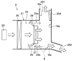
- the sound absorbing structure 10 of this embodiment is a sound absorbing structure using a fine perforated plate, and is applied to the air conditioning unit 2 shown in FIG.
- the air conditioning unit 2 blows conditioned air into the passenger compartment. That is, the air-conditioning unit 2 is a vehicle air-conditioning unit that is installed in the vehicle interior and performs air-conditioning in the vehicle interior.
- the air conditioning unit 2 includes an air conditioning case 21, a blower 23, an evaporator 26, a heater core 27, air mix doors 28 and 29, and a blowout opening door 254. Etc.
- the air conditioning case 21 is formed of a resin having a certain degree of elasticity and excellent in strength.
- the resin forming the air conditioning case 21 include polypropylene.
- the air conditioning case 21 forms an outer shell of the air conditioning unit 2, and an air passage, that is, a ventilation passage 24, through which air blown into the vehicle interior flows is formed inside the air conditioning case 21.
- the air conditioning case 21 has a plurality of blowing openings 251 and 252 for blowing air from the ventilation path 24 to a predetermined area in the passenger compartment on the downstream side of the ventilation path 24 in the air flow direction.
- a blower 23 In the air conditioning case 21, a blower 23, an evaporator 26, a heater core 27, air mix doors 28 and 29, and the like are provided.
- the blower 23 has a fan disposed in the ventilation path 24 and a motor that rotationally drives the fan.
- the blower 23 sucks in air that is inside air or outside air as the fan rotates, and causes the sucked air to flow through the air passage 24.
- the air introduced into the ventilation path 24 by the blower 23 flows through the ventilation path 24 and is blown out from any one of the plurality of blowing openings 251 and 252 into the vehicle interior.
- the air flow in the ventilation path 24 is indicated by white arrows.
- the inside air is the air inside the passenger compartment
- the outside air is the air outside the passenger compartment.
- the blowing opening door 254 is provided in the first blowing opening 251 among the plurality of blowing openings 251 and 252 and adjusts the opening area of the first blowing opening 251.
- the second outlet opening 252 of the plurality of outlet openings 251 and 252 is not provided with an outlet opening door, but the second outlet opening 252 also includes the first outlet opening.
- a blowout opening door may be provided.
- the evaporator 26 is a heat exchanger for cooling the air flowing through the ventilation path 24. Since the evaporator 26 is disposed downstream in the air flow direction with respect to the blower 23, the air blown from the blower 23 flows to the evaporator 26 in the ventilation path 24. The evaporator 26 exchanges heat between the air passing through the evaporator 26 and the refrigerant, thereby cooling the air and evaporating the refrigerant.
- the heater core 27 is a heat exchanger for heating the air flowing through the ventilation path 24.
- the heater core 27 exchanges heat between, for example, engine coolant and air passing through the heater core 27, and heats the air with the heat of the engine coolant. Further, the heater core 27 is disposed on the downstream side in the air flow direction with respect to the evaporator 26.
- the air passage 24 of the air conditioning case 21 includes bypass passages 24a and 24b that are formed in parallel to the heater core 27 and flow air by bypassing the heater core 27.
- Air mix doors 28 and 29 are provided between the evaporator 26 and the heater core 27 in the ventilation path 24 of the air conditioning unit 2.
- the air mix doors 28 and 29 pass between the evaporator 26 and the air volume that flows around the heater core 27 (that is, the air volume that flows through the bypass passages 24 a and 24 b) and the air volume that passes through the evaporator 26 and then passes through the heater core 27. Adjust the percentage.
- the sound absorbing structure 10 of the present embodiment is provided inside the air conditioning case 21 in order to absorb sound generated in the air conditioning case 21.
- the air conditioning case 21 has an installation range Wp in which the sound absorbing structure 10 can be installed, and the sound absorbing structure 10 is provided at any location within the installation range Wp or the entire installation range Wp. ing.
- the installation range Wp of the sound absorbing structure 10 includes the bypass passages 24a and 24b in the ventilation passage 24 and extends from the bypass passages 24a and 24b to the downstream side in the air flow direction.
- the installation range Wp is a hatched range in FIG. 2 is a diagram showing the sound absorbing structure 10 assuming that the sound absorbing structure 10 is provided in the II portion of FIG.
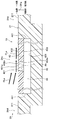
- the sound absorbing structure 10 includes a micro perforated plate 40 in which a plurality of fine through holes 401 are formed, and an opposing wall 42 arranged side by side with respect to the micro perforated plate 40.
- the fine perforated plate 40 of this embodiment is made of resin, for example.
- the facing wall 42 constitutes a part of the air conditioning case 21, it is made of the same resin as the air conditioning case 21.
- the fine perforated plate 40 has a thin plate shape and is fixed to the air conditioning case 21, for example.
- the micro perforated plate 40 is called, for example, MPP (that is, Micro-Perforated Panel).
- the fine perforated plate 40 has one surface 402 and another surface 403 opposite to the one surface 402.
- One surface 402 of the fine perforated plate 40 is a surface provided on one side of the fine perforated plate 40 in the axial direction DRa of the through hole 401.
- the other surface 403 is a surface provided on the other side in the axial direction DRa of the through hole 401 in the fine perforated plate 40.
- the one surface 402 of the fine perforated plate 40 faces the distribution space 24c through which a fluid (specifically, air) flows.
- a fluid specifically, air
- Each of the plurality of through holes 401 penetrates the fine perforated plate 40 from one surface 402 to the other surface 403. Therefore, the axial direction DRa of the through hole 401 is the same as the thickness direction of the fine perforated plate 40.
- the through-hole 401 of this embodiment is a hole of a circular cross section, for example.
- the axial direction DRa of the through hole 401 is also referred to as a hole axial direction DRa.
- each element such as the through hole 401 is displayed in a different size compared to the actual size in order to illustrate each element in an easy-to-understand manner. This is the same in each drawing described later.
- the distribution space 24c of FIG. 2 is included in the ventilation path 24 (see FIG. 1) in the air conditioning case 21 and is fine.
- the perforated plate 40 is provided in the air conditioning case 21.
- the fluid flowing in the circulation space 24 c is air flowing in the ventilation path 24.
- the air flow in the circulation space 24c is represented by an arrow FLa in FIG.
- the facing wall 42 is disposed so as to face the other surface 403 of the fine perforated plate 40 via the intervening air layer 44 (that is, the intervening space 44).
- the facing wall 42 has a facing surface 421 facing the intervening air layer 44, and the facing surface 421 faces the other surface 403 of the fine perforated plate 40.
- the facing surface 421 may or may not be parallel to the other surface 403 of the fine perforated plate 40.
- the hole cross-sectional area Ah of the through hole 401 of the fine perforated plate 40 is not constant in the cross section orthogonal to the hole axial direction DRa. Specifically, the through hole 401 is formed so that the hole cross-sectional area Ah becomes larger toward the other surface 403 side of the hole axial direction DRa.
- the through hole 401 of the fine perforated plate 40 has a cross-sectional area changing portion 401a in which the hole cross-sectional area Ah changes according to the position in the hole axial direction DRa.
- the cross-sectional area changing portion 401a of the present embodiment is a portion where the hole cross-sectional area Ah increases as the position in the hole axial direction DRa is closer to the other surface 403.
- the through hole 401 is formed in the other surface 403 from the position of the portion 402a in which the through hole 401 is formed in the one surface 402 of the fine perforated plate 40 in the hole axial direction DRa. It extends to the position of the part 403a. In short, the cross-sectional area changing portion 401 a reaches the entire length of the through hole 401.
- peripheral edge portion 441 of the intervening air layer 44 is closed by the air conditioning case 21 over the entire circumference.
- the sound absorbing structure 10 is provided with the fine perforated plate 40 and the opposing wall 42 as described above, the air in the through hole 401 of the fine perforated plate 40 is used as a mass, and the air in the intervening air layer 44 is used as a spring.
- a spring-mass system is constructed. Since the air around the through hole 401 vibrates due to the resonance frequency of the spring-mass system, the sound absorbing structure 10 absorbs the sound in the circulation space 24c.
- the air conditioning case 21 of the present embodiment is formed so that the case wall surface of the ventilation path 24 is not uneven due to the fine perforated plate 40 being provided in the air conditioning case 21.
- the ventilation path 24 in the air conditioning case 21 includes a connection space 24d connected to the distribution space 24c.
- the air conditioning case 21 has a connection space case surface 211 facing the connection space 24 d, and the micro perforated plate 40 is disposed so that one surface 402 of the micro perforated plate 40 is continuous with the connection space case surface 211. .
- the through hole 401 of the micro perforated plate 40 is formed such that the hole cross-sectional area Ah increases toward the other surface 403 side of the hole axial direction DRa. ing. Therefore, the opening area of the through-hole 401 with respect to the flow space 24c is set to a desired size while the volume of the through-hole 401 of the fine perforated plate 40 is set as compared with the case where the hole sectional area Ah of the through-hole 401 is constant. And can be made smaller. Therefore, it is possible to obtain a sound absorption effect in a target frequency band by the fine perforated plate 40 while suppressing the through-hole 401 from disturbing the fluid flow in the circulation space 24c. And noise deterioration can be prevented by suppressing the disturbance of the fluid flow in the circulation space 24c.
- the through hole 401 of the fine perforated plate 40 is formed by, for example, molding using a mold or the like, the die can be easily removed from the through hole 401, and therefore the fine perforated plate 40 can be easily manufactured. Is possible.
- the through hole 401 of the fine perforated plate 40 has the cross-sectional area changing portion 401a in which the hole cross-sectional area Ah increases as the position in the hole axial direction DRa is closer to the other surface 403.
- the through hole 401 is formed in the other surface 403 from the position of the portion 402a in which the through hole 401 is formed in the one surface 402 of the fine perforated plate 40 in the hole axial direction DRa. It extends to the position of the part 403a. Therefore, the opening area where the through-hole 401 opens with respect to the flow space 24c can be reduced by a gradual change in the hole cross-sectional area Ah.
- the facing wall 42 of the sound absorbing structure 10 constitutes a part of the air conditioning case 21.
- the distribution space 24 c facing the fine perforated plate 40 of the sound absorbing structure 10 is included in the ventilation path 24 formed in the air conditioning case 21, and the fine perforated plate 40 is provided in the air conditioning case 21. Therefore, before the noise of the air conditioning unit 2 leaks from the air conditioning case 21 to the outside, the noise can be reduced by the sound absorbing structure 10.
- the ventilation path 24 contains the connection space 24d connected to the distribution space 24c, and the air-conditioning case 21 has the connection space case surface 211 which faces the connection space 24d.
- the fine perforated plate 40 is arranged such that one surface 402 of the fine perforated plate 40 is continuous with the connected space case surface 211. Therefore, it is possible to arrange the fine perforated plate 40 so that the fine perforated plate 40 does not easily become an obstacle in the air flow in the ventilation path 24.
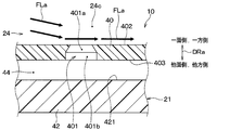
- the through hole 401 of the fine perforated plate 40 is formed such that the hole cross-sectional area Ah (see FIG. 2) of the through hole 401 increases toward the other surface 403 side of the hole axial direction DRa.
- the present embodiment is the same as the first embodiment.
- the cross-sectional area changing portion 401a does not reach the entire length of the through-hole 401, and is disposed so as to be biased toward the one surface 402 side of the hole axial direction DRa. That is, in the present embodiment, the through hole 401 of the fine perforated plate 40 has a cross-sectional area changing portion 401a and a cross-sectional area constant portion 401b having a constant hole cross-sectional area Ah regardless of the position in the hole axial direction DRa. Yes.
- the constant cross-sectional area portion 401b is a portion of the through hole 401 that extends in the hole axial direction DRa with a constant hole cross-sectional area Ah.
- the constant cross-sectional area portion 401b is arranged on the other surface 403 side of the hole axial direction DRa with respect to the cross-sectional area changing portion 401a.
- this embodiment is the same as the first embodiment. And in this embodiment, the effect show
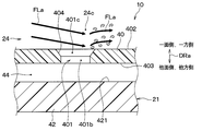
- the through hole 401 of the micro perforated plate 40 is formed so that the hole cross-sectional area Ah (see FIG. 2) of the through hole 401 becomes larger toward the other surface 403 side of the hole axial direction DRa. Absent.
- the present embodiment is different from the first embodiment.
- the through hole 401 of the fine perforated plate 40 has a one-surface-side open end 401c on the one surface 402 side of the hole axial direction DRa.
- the fine perforated plate 40 has a hole peripheral portion 404 formed so as to surround the one surface side open end 401c.
- the hole peripheral portion 404 has a chamfered shape (that is, a chamfered shape). Further, the hole peripheral portion 404 is formed without rising from the one surface 402 of the fine perforated plate 40 in the hole axial direction DRa.
- the chamfered shape of the hole peripheral portion 404 is a chamfered shape with a gradient surface.
- the “chamfered shape” simply defines the shape, and there is no limitation on the method of forming the “chamfered shape”.
- the portion of the through hole 401 excluding the one-surface-side opening end 401c is a constant cross-sectional area portion 401b. Therefore, in the portion of the micro perforated plate 40 where the through hole 401 is formed, the chamfered shape is provided on the one surface 402 side of the hole axial direction DRa, but is provided on the other surface 403 side. Not.
- this embodiment is the same as the first embodiment. And in this embodiment, the effect show
- the hole peripheral portion 404 of the fine perforated plate 40 has a chamfered shape, so that the fluid flow in the circulation space 24 c is disturbed due to the contact with the hole peripheral portion 404. Can be mitigated. Therefore, it is possible to obtain a sound absorption effect in a target frequency band by the fine perforated plate 40 while suppressing the through hole 401 of the fine perforated plate 40 from disturbing the fluid flow in the circulation space 24c. And noise deterioration can be prevented by suppressing the disturbance of the fluid flow in the circulation space 24c.
- the sound absorbing structure 10 of this embodiment includes an intervening space partition wall 46 in addition to the fine perforated plate 40 and the opposing wall 42.
- the intervening space partition wall 46 is provided between the fine perforated plate 40 and the opposing wall 42. That is, the intervening space partition wall 46 is disposed in the intervening air layer 44 (that is, the intervening space 44).
- the intervening space partition 46 partitions the intervening air layer 44 into a plurality of divided spaces 442.
- the intervening space partition wall 46 is provided as a partition wall that separates the plurality of divided spaces 442 from each other.
- the intervening air layer 44 of the present embodiment is composed of a plurality of divided spaces 442 partitioned by intervening space partition walls 46.
- the intervening space partition 46 is formed so that the shape seen from the hole axis direction DRa is a lattice shape.
- the interstitial space partition 46 is formed so as to extend along the hole axis direction DRa. Specifically, the side wall surfaces 461 and 462 on both sides of the intervening space partition wall 46 are formed so as to extend along the hole axis direction DRa at any location facing the divided space 442. This is because the sound propagation direction in the divided space 442 is aligned along the side wall surfaces 461 and 462.
- the intervening space partition 46 is connected to each of the fine perforated plate 40 and the opposing wall 42. That is, the intervening space partition wall 46 has one end 463 connected to the other surface 403 of the fine perforated plate 40 and the other end 464 connected to the facing surface 421 of the facing wall 42.
- this embodiment is the same as the first embodiment. And in this embodiment, the effect show
- the intervening space partition wall 46 is provided between the fine perforated plate 40 and the facing wall 42 and partitions the intervening air layer 44 into a plurality of divided spaces 442.
- the intervening space partition wall 46 is connected to each of the fine perforated plate 40 and the opposing wall 42. Therefore, it is possible to suppress the micro perforated plate 40 from being deformed by an external force, for example, by the intervening space partition wall 46.
- this embodiment is a modification based on 1st Embodiment, it is also possible to combine this embodiment with the above-mentioned 2nd or 3rd embodiment.
- the fine perforated plate 40 of the sound absorbing structure 10 is made of, for example, resin, but the material of the fine perforated plate 40 is not limited.
- the opposing wall 42 of the sound absorbing structure 10 is made of the same resin as the air conditioning case 21, but if it is molded as a separate member from the air conditioning case 21, May be of different materials. Furthermore, the material of the facing wall 42 is not limited.
- the sound absorbing structure 10 is used in the air conditioning unit 2, but may be used in devices other than the air conditioning unit 2. Absent. Accordingly, the fluid flowing in the circulation space 24c is air flowing in the ventilation path 24, but this is also an example. The fluid flowing in the circulation space 24c may be a fluid other than air.
- the chamfered shape of the hole peripheral portion 404 is a chamfered shape with a gradient surface. There is no problem even if the curved surface is a chamfered surface.
- FIG. 6 shows an example in which two through holes 401 are provided in the fine perforated plate 40 for each divided space 442, but this is an example. Any number of through holes 401 may be provided for each divided space 442. The number of through holes 401 provided for each divided space 442 need not be the same.
- the intervening space partition 46 is formed so that the shape viewed from the hole axis direction DRa is a lattice shape, but this is an example. .
- the shape of the intervening space partition wall 46 as viewed from the hole axial direction DRa is not limited, and the plurality of divided spaces 442 formed by the intervening space partition wall 46 do not need to have the same shape.
- this indication is not limited to the above-mentioned embodiment, It can implement by changing variously.
- a chamfered shape is provided around the opening end 401 c on the one surface side of the through-hole 401 in the fine perforated plate 40, but in embodiments other than the third embodiment, It is also conceivable that a chamfered shape is provided around the one-surface-side opening end 401c.
- a sound absorption structure is provided with a fine perforated board and an opposing wall.
- the micro perforated plate has one surface facing the flow space through which the fluid flows and the other surface opposite to the one surface, and the micro perforated plate has a through hole penetrating from one surface to the other surface. .
- the facing wall faces the other surface of the fine perforated plate via an intervening space.
- the through-hole is formed so that the hole cross-sectional area which the through-hole has in the cross section orthogonal to the axial direction of a through-hole becomes large toward the other surface side of an axial direction.
- the through hole has a one-surface-side opening end on one surface side
- the fine perforated plate has a hole peripheral portion formed so as to surround the one-surface-side opening end.
- the peripheral part of the hole has a chamfered shape.
- the third viewpoint is the same as the second viewpoint.
- the through hole has a cross-sectional area changing portion in which the hole cross-sectional area changes according to the position in the axial direction.
- the cross-sectional area changing portion extends in the axial direction from the position of the portion where the through hole is formed on one surface to the position of the portion where the through hole is formed on the other surface.
- the through hole has a cross-sectional area changing portion in which the hole cross-sectional area increases as the position in the axial direction is closer to the other surface.
- the cross-sectional area changing portion extends in the axial direction from the position of the portion where the through hole is formed on one surface to the position of the portion where the through hole is formed on the other surface. Therefore, the opening area in which the through hole opens with respect to the circulation space can be reduced by a gradual change in the hole cross-sectional area.
- the sound absorbing structure includes a partition wall provided between the fine perforated plate and the facing wall, and the partition partition the intervening space into a plurality of divided spaces. And the partition is connected with each of the fine perforated plate and the opposing wall. Therefore, it is possible to suppress the micro perforated plate from being deformed by an external force, for example, by the partition wall.
- the sound wave propagates along the partition wall in the divided space
- the sound wave propagates in the divided space in the direction along the partition wall regardless of the incident angle of the sound wave entering the through hole from the circulation space. It is possible to align. Thereby, it is possible to suppress the variation in the sound absorption frequency and improve the sound absorption rate of the sound absorption structure.
- the facing wall constitutes a part of the air conditioning case that forms the outer shell of the air conditioning unit that blows the conditioned air into the passenger compartment.
- the circulation space is included in an air passage formed in the air conditioning case, the fluid is air flowing through the air passage, and the fine perforated plate is provided in the air conditioning case. Therefore, before the noise of the air conditioning unit leaks from the air conditioning case to the outside, the noise can be reduced by the sound absorbing structure.
- the air passage includes a connection space connected to the distribution space, and the air conditioning case has a connection space case surface facing the connection space.
- the fine perforated plate is arranged so that one surface is continuous with the connected space case surface. Therefore, it is possible to arrange the fine perforated plate so that the fine perforated plate does not easily become an obstacle in the air flow in the air passage. Therefore, it is possible to suppress the disturbance of the air flow that can occur at the boundary between the location where the fine perforated plate is provided and the location where the fine perforated plate is not provided in the air conditioning case, and to suppress the generation of noise around the fine perforated plate.
Abstract
A sound absorbing structure comprises a finely perforated plate (40) and an opposing wall (42). The finely perforated plate has one surface (402) facing a flow space (24c) through which fluid flows and another surface (403) opposite to the one surface. A through hole (401) penetrating from the one surface to the other surface is formed in the finely perforated plate. The opposing wall faces the other surface of the finely perforated plate with an intervening space (44) therebetween. Further, the through hole is formed such that the hole cross-sectional area (Ah) of the through hole in the cross section orthogonal to the axial direction (DRa) of the through hole becomes larger toward the other surface side in the axial direction.
Description
本出願は、2018年5月24日に出願された日本特許出願番号2018-99590号に基づくもので、ここにその記載内容が参照により組み入れられる。
This application is based on Japanese Patent Application No. 2018-99590 filed on May 24, 2018, the contents of which are incorporated herein by reference.
本開示は、微細穿孔板を利用して吸音する吸音構造体に関するものである。
The present disclosure relates to a sound absorbing structure that absorbs sound using a fine perforated plate.
この種の吸音構造体で利用される微細穿孔板には複数の微細な貫通孔が形成されている。そして、その吸音構造体では、音場の壁や天井に対し空気層(別言すれば、介在空間)を介して微細穿孔板が配置される。このような配置により、微細穿孔板の貫通孔中の空気をマスとし、且つ壁や天井と微細穿孔板との間の空気層をバネとするバネ-マス系が構成される。そして、そのバネ-マス系の共鳴周波数により貫通孔周辺の空気が振動することで吸音が為される。
例えば特許文献1には上述したような吸音構造体が表されており、その特許文献1では、壁体から距離をおいて配置されるガラス建築部品に、微細な貫通孔が形成されている。そしてそのガラス建築部品が、吸音するための微細穿孔板として利用されている。 A plurality of fine through holes are formed in a fine perforated plate used in this type of sound absorbing structure. In the sound absorbing structure, a fine perforated plate is arranged through an air layer (in other words, an intervening space) with respect to the wall and ceiling of the sound field. Such an arrangement constitutes a spring-mass system in which the air in the through hole of the fine perforated plate is used as a mass and the air layer between the wall or ceiling and the fine perforated plate is used as a spring. The air around the through hole vibrates due to the resonance frequency of the spring-mass system, thereby absorbing sound.
For example, Patent Document 1 discloses a sound absorbing structure as described above. In Patent Document 1, a fine through-hole is formed in a glass building component arranged at a distance from a wall. The glass building component is used as a fine perforated plate for absorbing sound.
特許文献1の吸音構造体は、流体が流れる流通空間の音(すなわち、流れ場の音)を吸収するためのものではない。従って、流通空間における吸音を目的として、例えば特許文献1のガラス建築部品と同様の微細穿孔板を、何等対策せずに流通空間に面するように配置したとすれば、微細穿孔板の貫通孔の周辺にて流通空間内の流体流れが乱れるおそれがあった。そして、そのように流体流れが乱れると、それに起因した騒音が発生する。発明者らの詳細な検討の結果、以上のようなことが見出された。
The sound absorbing structure of Patent Document 1 is not intended to absorb the sound of the circulation space through which the fluid flows (that is, the sound of the flow field). Therefore, for the purpose of sound absorption in the distribution space, for example, if a fine perforated plate similar to the glass building component of Patent Document 1 is arranged so as to face the distribution space without taking any measures, the through hole of the fine perforated plate The fluid flow in the circulation space might be disturbed around And when the fluid flow is disturbed in such a way, noise resulting from it is generated. As a result of detailed studies by the inventors, the above has been found.
本開示は上記点に鑑みて、微細穿孔板の貫通孔が流通空間の流体流れを乱すことを抑制しつつ、微細穿孔板によって狙いの周波数帯の吸音効果を得ることが可能な吸音構造体を提供することを目的とする。
In view of the above points, the present disclosure provides a sound absorbing structure capable of obtaining a sound absorption effect in a target frequency band with a fine perforated plate while suppressing the through hole of the fine perforated plate from disturbing the fluid flow in the circulation space. The purpose is to provide.
上記目的を達成するため、本開示の1つの観点によれば、吸音構造体は、
微細穿孔板利用の吸音構造体であって、
流体が流れる流通空間に面する一面とその一面とは反対側の他面とを有し、一面から他面へ貫通した貫通孔が形成された微細穿孔板と、
微細穿孔板の他面に対し介在空間を介して対向する対向壁とを備え、
貫通孔の軸方向に直交する横断面においてその貫通孔が有する孔断面積が軸方向の他面側ほど大きくなるように、貫通孔は形成されている。 In order to achieve the above object, according to one aspect of the present disclosure, the sound absorbing structure includes:
A sound absorbing structure using a fine perforated plate,
A micro perforated plate having one surface facing the flow space through which the fluid flows and the other surface opposite to the one surface, in which a through hole penetrating from one surface to the other surface is formed;
An opposing wall facing the other surface of the fine perforated plate through an intervening space;
The through hole is formed so that the hole cross-sectional area of the through hole in the cross section orthogonal to the axial direction of the through hole becomes larger toward the other surface side in the axial direction.
このようにすれば、微細穿孔板の貫通孔の体積を所望の大きさとしつつ、貫通孔が流通空間に対して開口する開口面積を、貫通孔の孔断面積が一定である場合に比して小さくすることができる。従って、その貫通孔が流通空間の流体流れを乱すことを抑制しつつ、微細穿孔板によって狙いの周波数帯の吸音効果を得ることが可能である。
In this way, the volume of the through hole of the fine perforated plate is set to a desired size, and the opening area where the through hole opens with respect to the circulation space is compared with the case where the hole cross-sectional area of the through hole is constant. Can be small. Therefore, it is possible to obtain a sound absorption effect in a target frequency band by the fine perforated plate while suppressing the through-hole from disturbing the fluid flow in the circulation space.
また、本開示の別の観点によれば、吸音構造体は、
微細穿孔板利用の吸音構造体であって、
流体が流れる流通空間に面する一面とその一面とは反対側の他面とを有し、一面から他面へ貫通した貫通孔が形成された微細穿孔板と、
微細穿孔板の他面に対し介在空間を介して対向する対向壁とを備え、
貫通孔は、一面側に一面側開口端を有し、
微細穿孔板は、一面側開口端を取り囲んで形成する孔周縁部を有し、
その孔周縁部は、面取りされた形状となっている。 According to another aspect of the present disclosure, the sound absorbing structure is
A sound absorbing structure using a fine perforated plate,
A micro perforated plate having one surface facing the flow space through which the fluid flows and the other surface opposite to the one surface, in which a through hole penetrating from one surface to the other surface is formed;
An opposing wall facing the other surface of the fine perforated plate through an intervening space;
The through-hole has one open end on one side,
The micro-perforated plate has a hole peripheral portion formed so as to surround the one-surface-side open end,
The hole periphery has a chamfered shape.
このようにすれば、微細穿孔板の孔周縁部が面取りされた形状となっていることにより、流体流れがその孔周縁部に当たることに起因して乱れることを緩和することが可能である。従って、微細穿孔板の貫通孔が流通空間の流体流れを乱すことを抑制しつつ、微細穿孔板によって狙いの周波数帯の吸音効果を得ることが可能である。
In this way, it is possible to mitigate the disturbance caused by the fluid flow hitting the peripheral edge of the hole due to the chamfered shape of the peripheral edge of the fine perforated plate. Therefore, it is possible to obtain a sound absorption effect in a target frequency band by the fine perforated plate while suppressing the through hole of the fine perforated plate from disturbing the fluid flow in the circulation space.
なお、各構成要素等に付された括弧付きの参照符号は、その構成要素等と後述する実施形態に記載の具体的な構成要素等との対応関係の一例を示すものである。
Note that reference numerals with parentheses attached to each component and the like indicate an example of a correspondence relationship between the component and the like and specific components described in the embodiments described later.
以下、図面を参照しながら、各実施形態を説明する。なお、以下の各実施形態相互において、互いに同一もしくは均等である部分には、図中、同一符号を付してある。
Hereinafter, each embodiment will be described with reference to the drawings. In the following embodiments, the same or equivalent parts are denoted by the same reference numerals in the drawings.
(第1実施形態)
本実施形態の吸音構造体10は微細穿孔板利用の吸音構造体であり、図1に示す空調ユニット2に適用される。その空調ユニット2は車室内へ空調風を吹き出す。すなわち、その空調ユニット2は、車室内に設置され車室内の空調を行う車両用空調ユニットである。 (First embodiment)
Thesound absorbing structure 10 of this embodiment is a sound absorbing structure using a fine perforated plate, and is applied to the air conditioning unit 2 shown in FIG. The air conditioning unit 2 blows conditioned air into the passenger compartment. That is, the air-conditioning unit 2 is a vehicle air-conditioning unit that is installed in the vehicle interior and performs air-conditioning in the vehicle interior.
本実施形態の吸音構造体10は微細穿孔板利用の吸音構造体であり、図1に示す空調ユニット2に適用される。その空調ユニット2は車室内へ空調風を吹き出す。すなわち、その空調ユニット2は、車室内に設置され車室内の空調を行う車両用空調ユニットである。 (First embodiment)
The
図1および図2に示すように、その空調ユニット2は、吸音構造体10のほかに、空調ケース21、送風機23、エバポレータ26、ヒータコア27、エアミックスドア28、29、および吹出開口部ドア254などを有している。
As shown in FIGS. 1 and 2, in addition to the sound absorbing structure 10, the air conditioning unit 2 includes an air conditioning case 21, a blower 23, an evaporator 26, a heater core 27, air mix doors 28 and 29, and a blowout opening door 254. Etc.
空調ケース21は、ある程度の弾性を有し、強度的にも優れた樹脂にて形成されている。空調ケース21を形成する樹脂として、例えばポリプロピレンが挙げられる。図1に示すように、空調ケース21は空調ユニット2の外殻を成し、空調ケース21の内側には、車室内へ吹き出る空気が流通する空気通路すなわち通風路24が形成されている。
The air conditioning case 21 is formed of a resin having a certain degree of elasticity and excellent in strength. Examples of the resin forming the air conditioning case 21 include polypropylene. As shown in FIG. 1, the air conditioning case 21 forms an outer shell of the air conditioning unit 2, and an air passage, that is, a ventilation passage 24, through which air blown into the vehicle interior flows is formed inside the air conditioning case 21.
また、空調ケース21は、通風路24の空気流れ方向下流側に、通風路24から車室内の所定領域に空気を送風するための複数の吹出開口部251、252を有している。
In addition, the air conditioning case 21 has a plurality of blowing openings 251 and 252 for blowing air from the ventilation path 24 to a predetermined area in the passenger compartment on the downstream side of the ventilation path 24 in the air flow direction.
空調ケース21の内部には、送風機23、エバポレータ26、ヒータコア27、およびエアミックスドア28、29などが設けられている。
In the air conditioning case 21, a blower 23, an evaporator 26, a heater core 27, air mix doors 28 and 29, and the like are provided.
送風機23は、通風路24に配置されたファンと、そのファンを回転駆動するモータとを有している。送風機23は、ファンの回転により、内気または外気である空気を吸い込むと共に、その吸い込んだ空気を通風路24に流通させる。このようにして送風機23により通風路24に導入された空気は、その通風路24を流れ、複数の吹出開口部251、252のいずれかから車室内へと吹き出される。図1では、その通風路24内の空気流れが白抜き矢印で示されている。なお、内気とは車室内の空気であり、外気とは車室外の空気である。
The blower 23 has a fan disposed in the ventilation path 24 and a motor that rotationally drives the fan. The blower 23 sucks in air that is inside air or outside air as the fan rotates, and causes the sucked air to flow through the air passage 24. Thus, the air introduced into the ventilation path 24 by the blower 23 flows through the ventilation path 24 and is blown out from any one of the plurality of blowing openings 251 and 252 into the vehicle interior. In FIG. 1, the air flow in the ventilation path 24 is indicated by white arrows. The inside air is the air inside the passenger compartment, and the outside air is the air outside the passenger compartment.
吹出開口部ドア254は複数の吹出開口部251、252のうちの第1吹出開口部251に設けられており、その第1吹出開口部251の開口面積を調整する。なお、本実施形態では、複数の吹出開口部251、252のうちの第2吹出開口部252には吹出開口部ドアは設けられていないが、第2吹出開口部252にも第1吹出開口部251と同様に吹出開口部ドアが設けられていてもよい。
The blowing opening door 254 is provided in the first blowing opening 251 among the plurality of blowing openings 251 and 252 and adjusts the opening area of the first blowing opening 251. In the present embodiment, the second outlet opening 252 of the plurality of outlet openings 251 and 252 is not provided with an outlet opening door, but the second outlet opening 252 also includes the first outlet opening. Similarly to 251, a blowout opening door may be provided.
エバポレータ26は、通風路24を流れる空気を冷却するための熱交換器である。エバポレータ26は、送風機23に対し空気流れ方向下流側に配置されているので、送風機23から吹き出された空気は通風路24内でエバポレータ26に流れる。エバポレータ26は、エバポレータ26を通過する空気と冷媒とを熱交換させ、それにより、その空気を冷却すると共に冷媒を蒸発させる。
The evaporator 26 is a heat exchanger for cooling the air flowing through the ventilation path 24. Since the evaporator 26 is disposed downstream in the air flow direction with respect to the blower 23, the air blown from the blower 23 flows to the evaporator 26 in the ventilation path 24. The evaporator 26 exchanges heat between the air passing through the evaporator 26 and the refrigerant, thereby cooling the air and evaporating the refrigerant.
ヒータコア27は、通風路24を流れる空気を加熱するための熱交換器である。ヒータコア27は、例えばエンジン冷却水とヒータコア27を通過する空気とを熱交換させ、エンジン冷却水の熱で空気を加熱する。また、ヒータコア27は、エバポレータ26に対し空気流れ方向下流側に配置されている。
The heater core 27 is a heat exchanger for heating the air flowing through the ventilation path 24. The heater core 27 exchanges heat between, for example, engine coolant and air passing through the heater core 27, and heats the air with the heat of the engine coolant. Further, the heater core 27 is disposed on the downstream side in the air flow direction with respect to the evaporator 26.
また、空調ケース21の通風路24は、ヒータコア27に対し並列に形成されヒータコア27を迂回させて空気を流すバイパス通路24a、24bを含んでいる。
Further, the air passage 24 of the air conditioning case 21 includes bypass passages 24a and 24b that are formed in parallel to the heater core 27 and flow air by bypassing the heater core 27.
空調ユニット2の通風路24においてエバポレータ26とヒータコア27との間には、エアミックスドア28、29が設けられている。エアミックスドア28、29は、エバポレータ26を通過し、ヒータコア27を迂回して流れる風量(すなわち、バイパス通路24a、24bを流れる風量)と、エバポレータ26を通過した後にヒータコア27を通過する風量との割合を調整する。
Air mix doors 28 and 29 are provided between the evaporator 26 and the heater core 27 in the ventilation path 24 of the air conditioning unit 2. The air mix doors 28 and 29 pass between the evaporator 26 and the air volume that flows around the heater core 27 (that is, the air volume that flows through the bypass passages 24 a and 24 b) and the air volume that passes through the evaporator 26 and then passes through the heater core 27. Adjust the percentage.
本実施形態の吸音構造体10は、空調ケース21内で生じる音を吸収するために空調ケース21の内側に設けられている。具体的には、空調ケース21は吸音構造体10が設置されうる設置範囲Wpを有し、吸音構造体10は、その設置範囲Wp内の何れかの箇所またはその設置範囲Wpの全体に設けられている。
The sound absorbing structure 10 of the present embodiment is provided inside the air conditioning case 21 in order to absorb sound generated in the air conditioning case 21. Specifically, the air conditioning case 21 has an installation range Wp in which the sound absorbing structure 10 can be installed, and the sound absorbing structure 10 is provided at any location within the installation range Wp or the entire installation range Wp. ing.
その吸音構造体10の設置範囲Wpは、本実施形態では、通風路24のうち、バイパス通路24a、24bを含んでそのバイパス通路24a、24bから空気流れ方向下流側に及ぶ範囲となっている。要するに、その設置範囲Wpは、図1でハッチングが付された範囲となっている。なお、図2は、図1のII部分に吸音構造体10が設けられているとして、吸音構造体10を表示した図である。
In the present embodiment, the installation range Wp of the sound absorbing structure 10 includes the bypass passages 24a and 24b in the ventilation passage 24 and extends from the bypass passages 24a and 24b to the downstream side in the air flow direction. In short, the installation range Wp is a hatched range in FIG. 2 is a diagram showing the sound absorbing structure 10 assuming that the sound absorbing structure 10 is provided in the II portion of FIG.
図2に示すように、吸音構造体10は、複数の微細な貫通孔401が形成された微細穿孔板40と、その微細穿孔板40に対し並んで配置された対向壁42とを備えている。本実施形態の微細穿孔板40は例えば樹脂製である。また、対向壁42は空調ケース21の一部を構成しているので、その空調ケース21と同じ樹脂製である。
As shown in FIG. 2, the sound absorbing structure 10 includes a micro perforated plate 40 in which a plurality of fine through holes 401 are formed, and an opposing wall 42 arranged side by side with respect to the micro perforated plate 40. . The fine perforated plate 40 of this embodiment is made of resin, for example. Further, since the facing wall 42 constitutes a part of the air conditioning case 21, it is made of the same resin as the air conditioning case 21.
微細穿孔板40は薄肉の板状を成し、例えば空調ケース21に対して固定されている。この微細穿孔板40は、例えばMPP(すなわち、Micro-Perforated Panel)と称される。
The fine perforated plate 40 has a thin plate shape and is fixed to the air conditioning case 21, for example. The micro perforated plate 40 is called, for example, MPP (that is, Micro-Perforated Panel).
微細穿孔板40は、一面402と、その一面402とは反対側の他面403とを有している。微細穿孔板40の一面402は、微細穿孔板40のうち、貫通孔401の軸方向DRaでの一方側に設けられた表面である。そして、他面403は、微細穿孔板40のうち、貫通孔401の軸方向DRaでの他方側に設けられた表面である。
The fine perforated plate 40 has one surface 402 and another surface 403 opposite to the one surface 402. One surface 402 of the fine perforated plate 40 is a surface provided on one side of the fine perforated plate 40 in the axial direction DRa of the through hole 401. The other surface 403 is a surface provided on the other side in the axial direction DRa of the through hole 401 in the fine perforated plate 40.
微細穿孔板40の一面402は、流体(具体的には、空気)が流れる流通空間24cに面している。また、複数の貫通孔401はそれぞれ、微細穿孔板40を一面402から他面403へと貫通している。従って、その貫通孔401の軸方向DRaは微細穿孔板40の厚み方向と同じである。貫通孔401の孔断面形状に限定はないが、例えば本実施形態の貫通孔401は円形断面の孔である。なお、以下の説明では、貫通孔401の軸方向DRaを孔軸方向DRaとも呼ぶ。また、図2では、判りやすく各要素を図示するために、貫通孔401など各要素は実際の大きさと比較して異なる大きさで表示されている。このことは、後述の各図でも同様である。
The one surface 402 of the fine perforated plate 40 faces the distribution space 24c through which a fluid (specifically, air) flows. Each of the plurality of through holes 401 penetrates the fine perforated plate 40 from one surface 402 to the other surface 403. Therefore, the axial direction DRa of the through hole 401 is the same as the thickness direction of the fine perforated plate 40. Although there is no limitation in the hole cross-sectional shape of the through-hole 401, the through-hole 401 of this embodiment is a hole of a circular cross section, for example. In the following description, the axial direction DRa of the through hole 401 is also referred to as a hole axial direction DRa. Further, in FIG. 2, each element such as the through hole 401 is displayed in a different size compared to the actual size in order to illustrate each element in an easy-to-understand manner. This is the same in each drawing described later.
ここで、吸音構造体10は、上述したように空調ケース21の内側に設けられているので、図2の流通空間24cは空調ケース21内の通風路24(図1参照)に含まれ、微細穿孔板40は空調ケース21内に設けられている。そして、流通空間24cに流れる流体は、通風路24に流れる空気である。その流通空間24cの空気の流れは、図2では、矢印FLaで表されている。
Here, since the sound absorbing structure 10 is provided inside the air conditioning case 21 as described above, the distribution space 24c of FIG. 2 is included in the ventilation path 24 (see FIG. 1) in the air conditioning case 21 and is fine. The perforated plate 40 is provided in the air conditioning case 21. The fluid flowing in the circulation space 24 c is air flowing in the ventilation path 24. The air flow in the circulation space 24c is represented by an arrow FLa in FIG.
対向壁42は、微細穿孔板40の他面403に対し介在空気層44(すなわち、介在空間44)を介して対向するように配置されている。別言すれば、対向壁42は、介在空気層44に面する対向面421を有し、その対向面421が微細穿孔板40の他面403に対向している。なお、その対向面421は、微細穿孔板40の他面403に対し平行であってもなくてもよい。
The facing wall 42 is disposed so as to face the other surface 403 of the fine perforated plate 40 via the intervening air layer 44 (that is, the intervening space 44). In other words, the facing wall 42 has a facing surface 421 facing the intervening air layer 44, and the facing surface 421 faces the other surface 403 of the fine perforated plate 40. Note that the facing surface 421 may or may not be parallel to the other surface 403 of the fine perforated plate 40.
また、孔軸方向DRaに直交する横断面において微細穿孔板40の貫通孔401が有する孔断面積Ahは一定ではない。具体的には、その貫通孔401は、孔断面積Ahが孔軸方向DRaの他面403側ほど大きくなるように形成されている。
Further, the hole cross-sectional area Ah of the through hole 401 of the fine perforated plate 40 is not constant in the cross section orthogonal to the hole axial direction DRa. Specifically, the through hole 401 is formed so that the hole cross-sectional area Ah becomes larger toward the other surface 403 side of the hole axial direction DRa.
詳細には、微細穿孔板40の貫通孔401は、孔軸方向DRaの位置に応じて孔断面積Ahが変化する断面積変化部分401aを有している。厳密に言えば、本実施形態の断面積変化部分401aは、孔軸方向DRaの位置が他面403に近いほど孔断面積Ahが拡大する部分である。
Specifically, the through hole 401 of the fine perforated plate 40 has a cross-sectional area changing portion 401a in which the hole cross-sectional area Ah changes according to the position in the hole axial direction DRa. Strictly speaking, the cross-sectional area changing portion 401a of the present embodiment is a portion where the hole cross-sectional area Ah increases as the position in the hole axial direction DRa is closer to the other surface 403.
そして、その断面積変化部分401aは、孔軸方向DRaにおいて、微細穿孔板40の一面402のうち貫通孔401が形成された部位402aの位置から、他面403のうち貫通孔401が形成された部位403aの位置にまで及んでいる。要するに、その断面積変化部分401aは、貫通孔401の全長に及んでいる。
In the cross-sectional area changing portion 401a, the through hole 401 is formed in the other surface 403 from the position of the portion 402a in which the through hole 401 is formed in the one surface 402 of the fine perforated plate 40 in the hole axial direction DRa. It extends to the position of the part 403a. In short, the cross-sectional area changing portion 401 a reaches the entire length of the through hole 401.
また、介在空気層44の周縁部441は、その全周にわたり空調ケース21によって塞がれている。
Further, the peripheral edge portion 441 of the intervening air layer 44 is closed by the air conditioning case 21 over the entire circumference.
吸音構造体10では、上述したように微細穿孔板40と対向壁42とが設けられているので、微細穿孔板40の貫通孔401中の空気をマスとし且つ介在空気層44の空気をバネとするバネ-マス系が構成される。そして、そのバネ-マス系の共鳴周波数により貫通孔401周辺の空気が振動するので、これにより、吸音構造体10は流通空間24cの音を吸収する。
Since the sound absorbing structure 10 is provided with the fine perforated plate 40 and the opposing wall 42 as described above, the air in the through hole 401 of the fine perforated plate 40 is used as a mass, and the air in the intervening air layer 44 is used as a spring. A spring-mass system is constructed. Since the air around the through hole 401 vibrates due to the resonance frequency of the spring-mass system, the sound absorbing structure 10 absorbs the sound in the circulation space 24c.
また、本実施形態の空調ケース21は、微細穿孔板40が空調ケース21内に設けられたことに起因して通風路24のケース壁面に凹凸が生じることのないように形成されている。具体的に言うと、図1および図2に示すように、空調ケース21内の通風路24は、流通空間24cへつながる連結空間24dを含んでいる。そして、空調ケース21は、連結空間24dに面する連結空間ケース面211を有し、微細穿孔板40は、その微細穿孔板40の一面402が連結空間ケース面211に連なるように配置されている。
Further, the air conditioning case 21 of the present embodiment is formed so that the case wall surface of the ventilation path 24 is not uneven due to the fine perforated plate 40 being provided in the air conditioning case 21. Specifically, as shown in FIGS. 1 and 2, the ventilation path 24 in the air conditioning case 21 includes a connection space 24d connected to the distribution space 24c. The air conditioning case 21 has a connection space case surface 211 facing the connection space 24 d, and the micro perforated plate 40 is disposed so that one surface 402 of the micro perforated plate 40 is continuous with the connection space case surface 211. .
上述したように、本実施形態によれば、図2に示すように、微細穿孔板40の貫通孔401は、孔断面積Ahが孔軸方向DRaの他面403側ほど大きくなるように形成されている。そのため、微細穿孔板40の貫通孔401の体積を所望の大きさとしつつ、貫通孔401が流通空間24cに対して開口する開口面積を、貫通孔401の孔断面積Ahが一定である場合に比して小さくすることができる。従って、その貫通孔401が流通空間24cの流体流れを乱すことを抑制しつつ、微細穿孔板40によって狙いの周波数帯の吸音効果を得ることが可能である。そして、流通空間24cの流体流れの乱れを抑制することにより、騒音悪化を防止することが可能である。
As described above, according to the present embodiment, as shown in FIG. 2, the through hole 401 of the micro perforated plate 40 is formed such that the hole cross-sectional area Ah increases toward the other surface 403 side of the hole axial direction DRa. ing. Therefore, the opening area of the through-hole 401 with respect to the flow space 24c is set to a desired size while the volume of the through-hole 401 of the fine perforated plate 40 is set as compared with the case where the hole sectional area Ah of the through-hole 401 is constant. And can be made smaller. Therefore, it is possible to obtain a sound absorption effect in a target frequency band by the fine perforated plate 40 while suppressing the through-hole 401 from disturbing the fluid flow in the circulation space 24c. And noise deterioration can be prevented by suppressing the disturbance of the fluid flow in the circulation space 24c.
また、微細穿孔板40の貫通孔401が例えば金型等により型成形によって形成される場合には、その貫通孔401からの型抜きが容易になるので、微細穿孔板40を容易に製造することが可能である。
In addition, when the through hole 401 of the fine perforated plate 40 is formed by, for example, molding using a mold or the like, the die can be easily removed from the through hole 401, and therefore the fine perforated plate 40 can be easily manufactured. Is possible.
また、本実施形態によれば、微細穿孔板40の貫通孔401は、孔軸方向DRaの位置が他面403に近いほど孔断面積Ahが拡大する断面積変化部分401aを有している。そして、その断面積変化部分401aは、孔軸方向DRaにおいて、微細穿孔板40の一面402のうち貫通孔401が形成された部位402aの位置から、他面403のうち貫通孔401が形成された部位403aの位置にまで及んでいる。従って、緩やかな孔断面積Ahの変化で、貫通孔401が流通空間24cに対して開口する開口面積を小さくすることができる。
Further, according to the present embodiment, the through hole 401 of the fine perforated plate 40 has the cross-sectional area changing portion 401a in which the hole cross-sectional area Ah increases as the position in the hole axial direction DRa is closer to the other surface 403. In the cross-sectional area changing portion 401a, the through hole 401 is formed in the other surface 403 from the position of the portion 402a in which the through hole 401 is formed in the one surface 402 of the fine perforated plate 40 in the hole axial direction DRa. It extends to the position of the part 403a. Therefore, the opening area where the through-hole 401 opens with respect to the flow space 24c can be reduced by a gradual change in the hole cross-sectional area Ah.
また、本実施形態によれば、図1および図2に示すように、吸音構造体10の対向壁42は空調ケース21の一部を構成している。そして、吸音構造体10の微細穿孔板40が面する流通空間24cは、空調ケース21内に形成された通風路24に含まれ、微細穿孔板40は、空調ケース21内に設けられる。従って、空調ユニット2の騒音が空調ケース21から外部へ漏れ出る前に、その騒音を吸音構造体10によって低減することが可能である。
Further, according to the present embodiment, as shown in FIGS. 1 and 2, the facing wall 42 of the sound absorbing structure 10 constitutes a part of the air conditioning case 21. The distribution space 24 c facing the fine perforated plate 40 of the sound absorbing structure 10 is included in the ventilation path 24 formed in the air conditioning case 21, and the fine perforated plate 40 is provided in the air conditioning case 21. Therefore, before the noise of the air conditioning unit 2 leaks from the air conditioning case 21 to the outside, the noise can be reduced by the sound absorbing structure 10.
また、本実施形態によれば、通風路24は、流通空間24cへつながる連結空間24dを含み、空調ケース21は、連結空間24dに面する連結空間ケース面211を有している。そして、微細穿孔板40は、その微細穿孔板40の一面402が連結空間ケース面211に連なるように配置されている。そのため、通風路24での空気の流通において微細穿孔板40が障害物になりにくいように、微細穿孔板40を配置することが可能である。従って、空調ケース21内において微細穿孔板40を設けた箇所と設けていない箇所との境目で生じうる空気流れの乱れを抑制し、微細穿孔板40の周辺での騒音発生を抑制することが可能である。
Moreover, according to this embodiment, the ventilation path 24 contains the connection space 24d connected to the distribution space 24c, and the air-conditioning case 21 has the connection space case surface 211 which faces the connection space 24d. The fine perforated plate 40 is arranged such that one surface 402 of the fine perforated plate 40 is continuous with the connected space case surface 211. Therefore, it is possible to arrange the fine perforated plate 40 so that the fine perforated plate 40 does not easily become an obstacle in the air flow in the ventilation path 24. Therefore, it is possible to suppress the turbulence of the air flow that may occur at the boundary between the location where the fine perforated plate 40 is provided and the location where the fine perforated plate 40 is not provided in the air conditioning case 21, and to suppress noise generation around the fine perforated plate 40. It is.
(第2実施形態)
次に、第2実施形態について説明する。本実施形態では、前述の第1実施形態と異なる点を主として説明する。また、前述の実施形態と同一または均等な部分については省略または簡略化して説明する。このことは後述の実施形態の説明においても同様である。 (Second Embodiment)
Next, a second embodiment will be described. In the present embodiment, differences from the first embodiment will be mainly described. Further, the same or equivalent parts as those of the above-described embodiment will be described by omitting or simplifying them. The same applies to the description of the embodiments described later.
図3に示すように、微細穿孔板40の貫通孔401は、その貫通孔401の孔断面積Ah(図2参照)が孔軸方向DRaの他面403側ほど大きくなるように形成されている。この点では、本実施形態は第1実施形態と同様である。
As shown in FIG. 3, the through hole 401 of the fine perforated plate 40 is formed such that the hole cross-sectional area Ah (see FIG. 2) of the through hole 401 increases toward the other surface 403 side of the hole axial direction DRa. . In this respect, the present embodiment is the same as the first embodiment.
しかし、本実施形態では第1実施形態と異なり、断面積変化部分401aは、貫通孔401の全長に及んでおらず、孔軸方向DRaの一面402側に偏って配置されている。すなわち、本実施形態において、微細穿孔板40の貫通孔401は、断面積変化部分401aと、孔軸方向DRaの位置に拘わらず孔断面積Ahが一定の断面積一定部分401bとを有している。断面積一定部分401bとは、別言すれば、貫通孔401のうち孔断面積Ahを一定として孔軸方向DRaに延びている部分である。
However, in the present embodiment, unlike the first embodiment, the cross-sectional area changing portion 401a does not reach the entire length of the through-hole 401, and is disposed so as to be biased toward the one surface 402 side of the hole axial direction DRa. That is, in the present embodiment, the through hole 401 of the fine perforated plate 40 has a cross-sectional area changing portion 401a and a cross-sectional area constant portion 401b having a constant hole cross-sectional area Ah regardless of the position in the hole axial direction DRa. Yes. In other words, the constant cross-sectional area portion 401b is a portion of the through hole 401 that extends in the hole axial direction DRa with a constant hole cross-sectional area Ah.
そして、その断面積一定部分401bは、断面積変化部分401aに対し孔軸方向DRaの他面403側に配置されている。
The constant cross-sectional area portion 401b is arranged on the other surface 403 side of the hole axial direction DRa with respect to the cross-sectional area changing portion 401a.
以上説明したことを除き、本実施形態は第1実施形態と同様である。そして、本実施形態では、前述の第1実施形態と共通の構成から奏される効果を第1実施形態と同様に得ることができる。
Except as described above, this embodiment is the same as the first embodiment. And in this embodiment, the effect show | played from the structure common to the above-mentioned 1st Embodiment can be acquired similarly to 1st Embodiment.
(第3実施形態)
次に、第3実施形態について説明する。本実施形態では、前述の第1実施形態と異なる点を主として説明する。 (Third embodiment)
Next, a third embodiment will be described. In the present embodiment, differences from the first embodiment will be mainly described.
次に、第3実施形態について説明する。本実施形態では、前述の第1実施形態と異なる点を主として説明する。 (Third embodiment)
Next, a third embodiment will be described. In the present embodiment, differences from the first embodiment will be mainly described.
図4に示すように、微細穿孔板40の貫通孔401は、その貫通孔401の孔断面積Ah(図2参照)が孔軸方向DRaの他面403側ほど大きくなるようには形成されていない。この点で、本実施形態は第1実施形態と異なっている。
As shown in FIG. 4, the through hole 401 of the micro perforated plate 40 is formed so that the hole cross-sectional area Ah (see FIG. 2) of the through hole 401 becomes larger toward the other surface 403 side of the hole axial direction DRa. Absent. In this respect, the present embodiment is different from the first embodiment.
具体的に、微細穿孔板40の貫通孔401は、孔軸方向DRaの一面402側に一面側開口端401cを有している。そして、微細穿孔板40は、その一面側開口端401cを取り囲んで形成する孔周縁部404を有している。その孔周縁部404は、面取りされた形状(すなわち、面取り形状)となっている。また、孔周縁部404は、微細穿孔板40の一面402から孔軸方向DRaに盛り上がることなく形成されている。
Specifically, the through hole 401 of the fine perforated plate 40 has a one-surface-side open end 401c on the one surface 402 side of the hole axial direction DRa. The fine perforated plate 40 has a hole peripheral portion 404 formed so as to surround the one surface side open end 401c. The hole peripheral portion 404 has a chamfered shape (that is, a chamfered shape). Further, the hole peripheral portion 404 is formed without rising from the one surface 402 of the fine perforated plate 40 in the hole axial direction DRa.
本実施形態では、その孔周縁部404の面取りされた形状は、勾配面で面取りされた形状となっている。なお、「面取りされた形状」とは、単にその形状を定義しているだけであるので、その「面取りされた形状」を形成する方法に限定はない。
In the present embodiment, the chamfered shape of the hole peripheral portion 404 is a chamfered shape with a gradient surface. The “chamfered shape” simply defines the shape, and there is no limitation on the method of forming the “chamfered shape”.
また、貫通孔401のうち、一面側開口端401cを除いた部分は、断面積一定部分401bとなっている。従って、微細穿孔板40のうち貫通孔401が形成された部位において、上記の面取りされた形状は、孔軸方向DRaの一面402側には設けられているが、他面403側には設けられていない。
Further, the portion of the through hole 401 excluding the one-surface-side opening end 401c is a constant cross-sectional area portion 401b. Therefore, in the portion of the micro perforated plate 40 where the through hole 401 is formed, the chamfered shape is provided on the one surface 402 side of the hole axial direction DRa, but is provided on the other surface 403 side. Not.
以上説明したことを除き、本実施形態は第1実施形態と同様である。そして、本実施形態では、前述の第1実施形態と共通の構成から奏される効果を第1実施形態と同様に得ることができる。
Except as described above, this embodiment is the same as the first embodiment. And in this embodiment, the effect show | played from the structure common to the above-mentioned 1st Embodiment can be acquired similarly to 1st Embodiment.
また、本実施形態によれば、微細穿孔板40の孔周縁部404が面取りされた形状となっていることにより、流通空間24cの流体流れがその孔周縁部404に当たることに起因して乱れることを緩和することが可能である。従って、微細穿孔板40の貫通孔401が流通空間24cの流体流れを乱すことを抑制しつつ、微細穿孔板40によって狙いの周波数帯の吸音効果を得ることが可能である。そして、流通空間24cの流体流れの乱れを抑制することにより、騒音悪化を防止することが可能である。
Further, according to the present embodiment, the hole peripheral portion 404 of the fine perforated plate 40 has a chamfered shape, so that the fluid flow in the circulation space 24 c is disturbed due to the contact with the hole peripheral portion 404. Can be mitigated. Therefore, it is possible to obtain a sound absorption effect in a target frequency band by the fine perforated plate 40 while suppressing the through hole 401 of the fine perforated plate 40 from disturbing the fluid flow in the circulation space 24c. And noise deterioration can be prevented by suppressing the disturbance of the fluid flow in the circulation space 24c.
(第4実施形態)
次に、第4実施形態について説明する。本実施形態では、前述の第1実施形態と異なる点を主として説明する。 (Fourth embodiment)
Next, a fourth embodiment will be described. In the present embodiment, differences from the first embodiment will be mainly described.
次に、第4実施形態について説明する。本実施形態では、前述の第1実施形態と異なる点を主として説明する。 (Fourth embodiment)
Next, a fourth embodiment will be described. In the present embodiment, differences from the first embodiment will be mainly described.
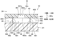
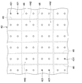
図5および図6に示すように、本実施形態の吸音構造体10は、微細穿孔板40と対向壁42とに加え、介在空間隔壁46を備えている。この介在空間隔壁46は、微細穿孔板40と対向壁42との間に設けられている。すなわち、介在空間隔壁46は、介在空気層44(すなわち、介在空間44)に配置されている。
As shown in FIGS. 5 and 6, the sound absorbing structure 10 of this embodiment includes an intervening space partition wall 46 in addition to the fine perforated plate 40 and the opposing wall 42. The intervening space partition wall 46 is provided between the fine perforated plate 40 and the opposing wall 42. That is, the intervening space partition wall 46 is disposed in the intervening air layer 44 (that is, the intervening space 44).
介在空間隔壁46は、介在空気層44を複数の分割空間442に仕切り分けている。すなわち、介在空間隔壁46は、その複数の分割空間442を相互に隔てる隔壁として設けられている。そして、本実施形態の介在空気層44は、介在空間隔壁46によって仕切り分けられた複数の分割空間442から構成されている。例えば、介在空間隔壁46は、孔軸方向DRaから見た形状が格子状になるように形成されている。
The intervening space partition 46 partitions the intervening air layer 44 into a plurality of divided spaces 442. In other words, the intervening space partition wall 46 is provided as a partition wall that separates the plurality of divided spaces 442 from each other. The intervening air layer 44 of the present embodiment is composed of a plurality of divided spaces 442 partitioned by intervening space partition walls 46. For example, the intervening space partition 46 is formed so that the shape seen from the hole axis direction DRa is a lattice shape.
また、介在空間隔壁46は、孔軸方向DRaに沿って延びるように形成されている。詳細に言えば、介在空間隔壁46が有する両側の側壁面461、462は、分割空間442に面する何れの箇所でも、孔軸方向DRaに沿って延びるように形成されている。分割空間442における音の伝播方向を側壁面461、462に沿わせて揃えるためである。
The interstitial space partition 46 is formed so as to extend along the hole axis direction DRa. Specifically, the side wall surfaces 461 and 462 on both sides of the intervening space partition wall 46 are formed so as to extend along the hole axis direction DRa at any location facing the divided space 442. This is because the sound propagation direction in the divided space 442 is aligned along the side wall surfaces 461 and 462.
介在空間隔壁46は、微細穿孔板40と対向壁42とのそれぞれに連結している。すなわち、介在空間隔壁46は、微細穿孔板40の他面403に連結する一端463と、対向壁42の対向面421に連結する他端464とを有している。
The intervening space partition 46 is connected to each of the fine perforated plate 40 and the opposing wall 42. That is, the intervening space partition wall 46 has one end 463 connected to the other surface 403 of the fine perforated plate 40 and the other end 464 connected to the facing surface 421 of the facing wall 42.
なお、介在空間隔壁46と微細穿孔板40の他面403との間、および、介在空間隔壁46と対向壁42の対向面421との間に気密性は必要ない。従って、その介在空間隔壁46と微細穿孔板40の他面403との間、および、介在空間隔壁46と対向壁42の対向面421との間には、多少の隙間が生じていても構わない。
Note that airtightness is not required between the intervening space partition wall 46 and the other surface 403 of the fine perforated plate 40 and between the intervening space partition wall 46 and the facing surface 421 of the facing wall 42. Therefore, a slight gap may be generated between the intervening space partition wall 46 and the other surface 403 of the fine perforated plate 40 and between the intervening space partition wall 46 and the facing surface 421 of the facing wall 42. .
以上説明したことを除き、本実施形態は第1実施形態と同様である。そして、本実施形態では、前述の第1実施形態と共通の構成から奏される効果を第1実施形態と同様に得ることができる。
Except as described above, this embodiment is the same as the first embodiment. And in this embodiment, the effect show | played from the structure common to the above-mentioned 1st Embodiment can be acquired similarly to 1st Embodiment.
また、本実施形態によれば、介在空間隔壁46は、微細穿孔板40と対向壁42との間に設けられ、介在空気層44を複数の分割空間442に仕切り分けている。そして、介在空間隔壁46は、微細穿孔板40と対向壁42とのそれぞれに連結している。従って、微細穿孔板40が例えば外力により変形することを、その介在空間隔壁46で抑制することが可能である。
Further, according to the present embodiment, the intervening space partition wall 46 is provided between the fine perforated plate 40 and the facing wall 42 and partitions the intervening air layer 44 into a plurality of divided spaces 442. The intervening space partition wall 46 is connected to each of the fine perforated plate 40 and the opposing wall 42. Therefore, it is possible to suppress the micro perforated plate 40 from being deformed by an external force, for example, by the intervening space partition wall 46.
ここで、分割空間442内では音波が介在空間隔壁46の側壁面461、462に沿って伝播する。従って、その音波が分割空間442内で伝播する向きを、流通空間24cから貫通孔401へ入射する音波の入射角に拘わらず、介在空間隔壁46の側壁面461、462に沿った向きに揃えることが可能である。これにより、吸音周波数のバラツキを抑え、吸音構造体10の吸音率を向上させることが可能である。
Here, in the divided space 442, sound waves propagate along the side wall surfaces 461 and 462 of the intervening space partition wall 46. Therefore, the direction in which the sound wave propagates in the divided space 442 is aligned with the direction along the side wall surfaces 461 and 462 of the interstitial space partition wall 46 regardless of the incident angle of the sound wave that enters the through hole 401 from the circulation space 24c. Is possible. Thereby, it is possible to suppress variation in the sound absorption frequency and improve the sound absorption rate of the sound absorption structure 10.
なお、本実施形態は第1実施形態に基づいた変形例であるが、本実施形態を前述の第2または第3実施形態と組み合わせることも可能である。
In addition, although this embodiment is a modification based on 1st Embodiment, it is also possible to combine this embodiment with the above-mentioned 2nd or 3rd embodiment.
(他の実施形態)
(1)上述の各実施形態において、吸音構造体10の微細穿孔板40は例えば樹脂製であるが、その微細穿孔板40の材質に限定はない。 (Other embodiments)
(1) In each of the above-described embodiments, the fineperforated plate 40 of the sound absorbing structure 10 is made of, for example, resin, but the material of the fine perforated plate 40 is not limited.
(1)上述の各実施形態において、吸音構造体10の微細穿孔板40は例えば樹脂製であるが、その微細穿孔板40の材質に限定はない。 (Other embodiments)
(1) In each of the above-described embodiments, the fine
(2)上述の各実施形態において、吸音構造体10の対向壁42は空調ケース21と同じ樹脂製であるが、その空調ケース21と別個の部材として成形されるのであれば、空調ケース21とは異なる材質であってもよい。更に言えば、その対向壁42の材質に限定はない。
(2) In each of the embodiments described above, the opposing wall 42 of the sound absorbing structure 10 is made of the same resin as the air conditioning case 21, but if it is molded as a separate member from the air conditioning case 21, May be of different materials. Furthermore, the material of the facing wall 42 is not limited.
(3)上述の各実施形態では、例えば図1および図2に示すように、吸音構造体10は空調ユニット2に用いられているが、空調ユニット2以外の他の装置に用いられても差し支えない。従って、流通空間24cに流れる流体は、通風路24に流れる空気であるが、これも一例である。その流通空間24cに流れる流体は、空気以外の流体であっても差し支えない。
(3) In each of the embodiments described above, for example, as shown in FIGS. 1 and 2, the sound absorbing structure 10 is used in the air conditioning unit 2, but may be used in devices other than the air conditioning unit 2. Absent. Accordingly, the fluid flowing in the circulation space 24c is air flowing in the ventilation path 24, but this is also an example. The fluid flowing in the circulation space 24c may be a fluid other than air.
(4)上述の第3実施形態では、図4に示すように、孔周縁部404の面取りされた形状は、勾配面で面取りされた形状となっているが、これに限らず、例えば、凸曲面であるR面で面取りされた形状となっていても差し支えない。
(4) In the third embodiment described above, as shown in FIG. 4, the chamfered shape of the hole peripheral portion 404 is a chamfered shape with a gradient surface. There is no problem even if the curved surface is a chamfered surface.
(5)上述の第4実施形態において、図6は、分割空間442毎に2つの貫通孔401が微細穿孔板40に設けられた図示となっているが、これは一例である。分割空間442毎に設けられる貫通孔401の数はいくつでもよい。そして、分割空間442毎に設けられる貫通孔401の数は互いに同じである必要もない。
(5) In the above-described fourth embodiment, FIG. 6 shows an example in which two through holes 401 are provided in the fine perforated plate 40 for each divided space 442, but this is an example. Any number of through holes 401 may be provided for each divided space 442. The number of through holes 401 provided for each divided space 442 need not be the same.
(6)上述の第4実施形態では、図6に示すように、介在空間隔壁46は、孔軸方向DRaから見た形状が格子状になるように形成されているが、これは一例である。その孔軸方向DRaから見た介在空間隔壁46の形状に限定はなく、その介在空間隔壁46が形成する複数の分割空間442が互いに同形状である必要もない。
(6) In the fourth embodiment described above, as shown in FIG. 6, the intervening space partition 46 is formed so that the shape viewed from the hole axis direction DRa is a lattice shape, but this is an example. . The shape of the intervening space partition wall 46 as viewed from the hole axial direction DRa is not limited, and the plurality of divided spaces 442 formed by the intervening space partition wall 46 do not need to have the same shape.
(7)なお、本開示は、上述の実施形態に限定されることなく、種々変形して実施することができる。
(7) In addition, this indication is not limited to the above-mentioned embodiment, It can implement by changing variously.
また、上記各実施形態は、互いに無関係なものではなく、組み合わせが明らかに不可な場合を除き、適宜組み合わせが可能である。例えば図4に示すように、第3実施形態では微細穿孔板40のうち、貫通孔401の一面側開口端401c周りに面取り形状が設けられているが、第3実施形態以外の実施形態において、一面側開口端401c周りに面取り形状が設けられていることも考え得る。
Further, the above embodiments are not irrelevant to each other, and can be appropriately combined unless the combination is clearly impossible. For example, as shown in FIG. 4, in the third embodiment, a chamfered shape is provided around the opening end 401 c on the one surface side of the through-hole 401 in the fine perforated plate 40, but in embodiments other than the third embodiment, It is also conceivable that a chamfered shape is provided around the one-surface-side opening end 401c.
また、上記各実施形態において、実施形態を構成する要素は、特に必須であると明示した場合および原理的に明らかに必須であると考えられる場合等を除き、必ずしも必須のものではないことは言うまでもない。また、上記各実施形態において、実施形態の構成要素の個数、数値、量、範囲等の数値が言及されている場合、特に必須であると明示した場合および原理的に明らかに特定の数に限定される場合等を除き、その特定の数に限定されるものではない。また、上記各実施形態において、構成要素等の材質、形状、位置関係等に言及するときは、特に明示した場合および原理的に特定の材質、形状、位置関係等に限定される場合等を除き、その材質、形状、位置関係等に限定されるものではない。
In each of the above-described embodiments, it is needless to say that elements constituting the embodiment are not necessarily essential unless explicitly stated as essential and clearly considered essential in principle. Yes. Further, in each of the above embodiments, when numerical values such as the number, numerical value, quantity, range, etc. of the constituent elements of the embodiment are mentioned, it is clearly limited to a specific number when clearly indicated as essential and in principle. The number is not limited to the specific number except for the case. In each of the above embodiments, when referring to the material, shape, positional relationship, etc. of the constituent elements, etc., unless otherwise specified, or in principle limited to a specific material, shape, positional relationship, etc. The material, shape, positional relationship, etc. are not limited.
(まとめ)
上記各実施形態の一部または全部で示された第1の観点によれば、吸音構造体は微細穿孔板と対向壁とを備える。その微細穿孔板は、流体が流れる流通空間に面する一面とその一面とは反対側の他面とを有し、微細穿孔板には、一面から他面へ貫通した貫通孔が形成されている。対向壁は、微細穿孔板の他面に対し介在空間を介して対向する。そして、貫通孔の軸方向に直交する横断面においてその貫通孔が有する孔断面積が軸方向の他面側ほど大きくなるように、貫通孔は形成されている。 (Summary)
According to the 1st viewpoint shown by one part or all part of said each embodiment, a sound absorption structure is provided with a fine perforated board and an opposing wall. The micro perforated plate has one surface facing the flow space through which the fluid flows and the other surface opposite to the one surface, and the micro perforated plate has a through hole penetrating from one surface to the other surface. . The facing wall faces the other surface of the fine perforated plate via an intervening space. And the through-hole is formed so that the hole cross-sectional area which the through-hole has in the cross section orthogonal to the axial direction of a through-hole becomes large toward the other surface side of an axial direction.
また、第2の観点によれば、貫通孔は、一面側に一面側開口端を有し、微細穿孔板は、その一面側開口端を取り囲んで形成する孔周縁部を有する。そして、その孔周縁部は、面取りされた形状となっている。第3の観点も、この第2の観点と同様である。
Further, according to the second aspect, the through hole has a one-surface-side opening end on one surface side, and the fine perforated plate has a hole peripheral portion formed so as to surround the one-surface-side opening end. And the peripheral part of the hole has a chamfered shape. The third viewpoint is the same as the second viewpoint.
また、第4の観点によれば、貫通孔は、軸方向の位置に応じて孔断面積が変化する断面積変化部分を有する。そして、その断面積変化部分は、軸方向において、一面のうち貫通孔が形成された部位の位置から、他面のうち貫通孔が形成された部位の位置にまで及んでいる。
Further, according to the fourth aspect, the through hole has a cross-sectional area changing portion in which the hole cross-sectional area changes according to the position in the axial direction. The cross-sectional area changing portion extends in the axial direction from the position of the portion where the through hole is formed on one surface to the position of the portion where the through hole is formed on the other surface.
また、第5の観点によれば、貫通孔は、軸方向の位置が他面に近いほど孔断面積が拡大する断面積変化部分を有する。そして、その断面積変化部分は、軸方向において、一面のうち貫通孔が形成された部位の位置から、他面のうち貫通孔が形成された部位の位置にまで及んでいる。従って、緩やかな孔断面積の変化で、貫通孔が流通空間に対して開口する開口面積を小さくすることができる。
Further, according to the fifth aspect, the through hole has a cross-sectional area changing portion in which the hole cross-sectional area increases as the position in the axial direction is closer to the other surface. The cross-sectional area changing portion extends in the axial direction from the position of the portion where the through hole is formed on one surface to the position of the portion where the through hole is formed on the other surface. Therefore, the opening area in which the through hole opens with respect to the circulation space can be reduced by a gradual change in the hole cross-sectional area.
また、第6の観点によれば、吸音構造体は、微細穿孔板と対向壁との間に設けられた隔壁を備え、その隔壁は、介在空間を複数の分割空間に仕切り分ける。そして、その隔壁は、微細穿孔板と対向壁とのそれぞれに連結している。従って、微細穿孔板が例えば外力により変形することを、その隔壁で抑制することが可能である。
Further, according to the sixth aspect, the sound absorbing structure includes a partition wall provided between the fine perforated plate and the facing wall, and the partition partition the intervening space into a plurality of divided spaces. And the partition is connected with each of the fine perforated plate and the opposing wall. Therefore, it is possible to suppress the micro perforated plate from being deformed by an external force, for example, by the partition wall.
また、分割空間内では音波が隔壁に沿って伝播するので、その音波が分割空間内で伝播する向きを、流通空間から貫通孔へ入射する音波の入射角に拘わらず、隔壁に沿った向きに揃えることが可能である。これにより、吸音周波数のバラツキを抑え、吸音構造体の吸音率を向上させることが可能である。
In addition, since the sound wave propagates along the partition wall in the divided space, the sound wave propagates in the divided space in the direction along the partition wall regardless of the incident angle of the sound wave entering the through hole from the circulation space. It is possible to align. Thereby, it is possible to suppress the variation in the sound absorption frequency and improve the sound absorption rate of the sound absorption structure.
また、第7の観点によれば、対向壁は、車室内へ空調風を吹き出す空調ユニットの外殻を成す空調ケースの一部を構成する。そして、流通空間は、空調ケース内に形成された空気通路に含まれ、上記流体は、空気通路に流れる空気であり、微細穿孔板は、空調ケース内に設けられる。従って、空調ユニットの騒音が空調ケースから外部へ漏れ出る前に、その騒音を吸音構造体によって低減することが可能である。
Further, according to the seventh aspect, the facing wall constitutes a part of the air conditioning case that forms the outer shell of the air conditioning unit that blows the conditioned air into the passenger compartment. The circulation space is included in an air passage formed in the air conditioning case, the fluid is air flowing through the air passage, and the fine perforated plate is provided in the air conditioning case. Therefore, before the noise of the air conditioning unit leaks from the air conditioning case to the outside, the noise can be reduced by the sound absorbing structure.
また、第8の観点によれば、空気通路は、流通空間へつながる連結空間を含み、空調ケースは、連結空間に面する連結空間ケース面を有する。そして、微細穿孔板は、一面が連結空間ケース面に連なるように配置される。そのため、空気通路での空気の流通において微細穿孔板が障害物になりにくいように、微細穿孔板を配置することが可能である。従って、空調ケース内において微細穿孔板を設けた箇所と設けていない箇所との境目で生じうる空気流れの乱れを抑制し、微細穿孔板の周辺での騒音発生を抑制することが可能である。
Further, according to the eighth aspect, the air passage includes a connection space connected to the distribution space, and the air conditioning case has a connection space case surface facing the connection space. The fine perforated plate is arranged so that one surface is continuous with the connected space case surface. Therefore, it is possible to arrange the fine perforated plate so that the fine perforated plate does not easily become an obstacle in the air flow in the air passage. Therefore, it is possible to suppress the disturbance of the air flow that can occur at the boundary between the location where the fine perforated plate is provided and the location where the fine perforated plate is not provided in the air conditioning case, and to suppress the generation of noise around the fine perforated plate.
Claims (8)
- 微細穿孔板利用の吸音構造体であって、
流体が流れる流通空間(24c)に面する一面(402)と該一面とは反対側の他面(403)とを有し、前記一面から前記他面へ貫通した貫通孔(401)が形成された微細穿孔板(40)と、
前記微細穿孔板の前記他面に対し介在空間(44)を介して対向する対向壁(42)とを備え、
前記貫通孔の軸方向(DRa)に直交する横断面において該貫通孔が有する孔断面積(Ah)が前記軸方向の前記他面側ほど大きくなるように、前記貫通孔は形成されている、吸音構造体。 A sound absorbing structure using a fine perforated plate,
A through hole (401) having one surface (402) facing the circulation space (24c) through which the fluid flows and the other surface (403) opposite to the one surface and penetrating from the one surface to the other surface is formed. A fine perforated plate (40),
An opposing wall (42) facing the other surface of the fine perforated plate via an intervening space (44),
The through hole is formed such that a hole cross-sectional area (Ah) of the through hole in a cross section orthogonal to the axial direction (DRa) of the through hole is increased toward the other surface side in the axial direction. Sound absorbing structure. - 前記貫通孔は、前記一面側に一面側開口端(401c)を有し、
前記微細穿孔板は、前記一面側開口端を取り囲んで形成する孔周縁部(404)を有し、
該孔周縁部は、面取りされた形状となっている、請求項1に記載の吸音構造体。 The through hole has a first surface side open end (401c) on the first surface side,
The fine perforated plate has a hole peripheral portion (404) formed so as to surround the one-surface-side open end,
The sound absorbing structure according to claim 1, wherein the hole peripheral portion has a chamfered shape. - 微細穿孔板利用の吸音構造体であって、
流体が流れる流通空間(24c)に面する一面(402)と該一面とは反対側の他面(403)とを有し、前記一面から前記他面へ貫通した貫通孔(401)が形成された微細穿孔板(40)と、
前記微細穿孔板の前記他面に対し介在空間(44)を介して対向する対向壁(42)とを備え、
前記貫通孔は、前記一面側に一面側開口端(401c)を有し、
前記微細穿孔板は、前記一面側開口端を取り囲んで形成する孔周縁部(404)を有し、
該孔周縁部は、面取りされた形状となっている、吸音構造体。 A sound absorbing structure using a fine perforated plate,
A through hole (401) having one surface (402) facing the circulation space (24c) through which the fluid flows and the other surface (403) opposite to the one surface and penetrating from the one surface to the other surface is formed. A fine perforated plate (40),
An opposing wall (42) facing the other surface of the fine perforated plate via an intervening space (44),
The through hole has a first surface side open end (401c) on the first surface side,
The fine perforated plate has a hole peripheral portion (404) formed so as to surround the one-surface-side open end,
The hole peripheral portion is a sound absorbing structure having a chamfered shape. - 前記貫通孔は、前記軸方向の位置に応じて前記孔断面積が変化する断面積変化部分(401a)を有し、
該断面積変化部分は、前記軸方向において、前記一面のうち前記貫通孔が形成された部位(402a)の位置から、前記他面のうち前記貫通孔が形成された部位(403a)の位置にまで及んでいる、請求項1または2に記載の吸音構造体。 The through hole has a cross-sectional area changing portion (401a) in which the hole cross-sectional area changes according to the position in the axial direction,
The cross-sectional area changing portion is located in the axial direction from the position of the portion (402a) where the through hole is formed in the one surface to the position of the portion (403a) where the through hole is formed in the other surface. The sound-absorbing structure according to claim 1 or 2, wherein - 前記貫通孔は、前記軸方向の位置が前記他面に近いほど前記孔断面積が拡大する断面積変化部分(401a)を有し、
該断面積変化部分は、前記軸方向において、前記一面のうち前記貫通孔が形成された部位(402a)の位置から、前記他面のうち前記貫通孔が形成された部位(403a)の位置にまで及んでいる、請求項1に記載の吸音構造体。 The through-hole has a cross-sectional area changing portion (401a) in which the hole cross-sectional area expands as the axial position is closer to the other surface,
The cross-sectional area changing portion is located in the axial direction from the position of the portion (402a) where the through hole is formed in the one surface to the position of the portion (403a) where the through hole is formed in the other surface. The sound absorbing structure according to claim 1, wherein - 前記微細穿孔板と前記対向壁との間に設けられ、前記介在空間を複数の分割空間(442)に仕切り分ける隔壁(46)を備え、
前記隔壁は、前記微細穿孔板と前記対向壁とのそれぞれに連結している、請求項1ないし5のいずれか1つに記載の吸音構造体。 Provided with a partition wall (46) provided between the micro perforated plate and the opposing wall and partitioning the intervening space into a plurality of divided spaces (442);
The sound absorbing structure according to claim 1, wherein the partition wall is connected to each of the fine perforated plate and the facing wall. - 前記対向壁は、車室内へ空調風を吹き出す空調ユニット(2)の外殻を成す空調ケース(21)の一部を構成し、
前記流通空間は、前記空調ケース内に形成された空気通路(24)に含まれ、
前記流体は、前記空気通路に流れる空気であり、
前記微細穿孔板は、前記空調ケース内に設けられる、請求項1ないし6のいずれか1つに記載の吸音構造体。 The opposing wall constitutes a part of the air conditioning case (21) that forms the outer shell of the air conditioning unit (2) that blows the air conditioned air into the passenger compartment.
The distribution space is included in an air passage (24) formed in the air conditioning case,
The fluid is air flowing through the air passage;
The sound absorbing structure according to claim 1, wherein the fine perforated plate is provided in the air conditioning case. - 前記空気通路は、前記流通空間へつながる連結空間(24d)を含み、
前記空調ケースは、前記連結空間に面する連結空間ケース面(211)を有し、
前記微細穿孔板は、前記一面が連結空間ケース面に連なるように配置される、請求項7に記載の吸音構造体。
The air passage includes a connection space (24d) connected to the circulation space,
The air conditioning case has a connected space case surface (211) facing the connected space,
The sound absorbing structure according to claim 7, wherein the fine perforated plate is arranged so that the one surface is continuous with a connected space case surface.
Applications Claiming Priority (2)
| Application Number | Priority Date | Filing Date | Title |
|---|---|---|---|
| JP2018099590A JP2019204010A (en) | 2018-05-24 | 2018-05-24 | Sound absorbing structure |
| JP2018-099590 | 2018-05-24 |
Publications (1)
| Publication Number | Publication Date |
|---|---|
| WO2019225293A1 true WO2019225293A1 (en) | 2019-11-28 |
Family
ID=68616609
Family Applications (1)
| Application Number | Title | Priority Date | Filing Date |
|---|---|---|---|
| PCT/JP2019/017775 WO2019225293A1 (en) | 2018-05-24 | 2019-04-25 | Sound absorbing structure |
Country Status (2)
| Country | Link |
|---|---|
| JP (1) | JP2019204010A (en) |
| WO (1) | WO2019225293A1 (en) |
Cited By (1)
| Publication number | Priority date | Publication date | Assignee | Title |
|---|---|---|---|---|
| EP4270379A1 (en) * | 2022-04-29 | 2023-11-01 | RTX Corporation | Face sheet of acoustic liner having streamlined holes with elongated edges |
Citations (5)
| Publication number | Priority date | Publication date | Assignee | Title |
|---|---|---|---|---|
| JP2003015656A (en) * | 2001-07-04 | 2003-01-17 | National Aerospace Laboratory Of Japan | Fine jet control type sound absorption system |
| JP2006113323A (en) * | 2004-10-15 | 2006-04-27 | Kobe Steel Ltd | Porous-plate sound absorbing structure |
| JP2007024039A (en) * | 2005-07-13 | 2007-02-01 | United Technol Corp <Utc> | Liner assembly and face sheet panel assembly |
| JP2008231956A (en) * | 2007-03-16 | 2008-10-02 | Daikyo Nishikawa Kk | Sound absorbing structure |
| WO2017090538A1 (en) * | 2015-11-27 | 2017-06-01 | 株式会社神戸製鋼所 | Porous sound-absorbing board |
-
2018
- 2018-05-24 JP JP2018099590A patent/JP2019204010A/en active Pending
-
2019
- 2019-04-25 WO PCT/JP2019/017775 patent/WO2019225293A1/en active Application Filing
Patent Citations (5)
| Publication number | Priority date | Publication date | Assignee | Title |
|---|---|---|---|---|
| JP2003015656A (en) * | 2001-07-04 | 2003-01-17 | National Aerospace Laboratory Of Japan | Fine jet control type sound absorption system |
| JP2006113323A (en) * | 2004-10-15 | 2006-04-27 | Kobe Steel Ltd | Porous-plate sound absorbing structure |
| JP2007024039A (en) * | 2005-07-13 | 2007-02-01 | United Technol Corp <Utc> | Liner assembly and face sheet panel assembly |
| JP2008231956A (en) * | 2007-03-16 | 2008-10-02 | Daikyo Nishikawa Kk | Sound absorbing structure |
| WO2017090538A1 (en) * | 2015-11-27 | 2017-06-01 | 株式会社神戸製鋼所 | Porous sound-absorbing board |
Cited By (2)
| Publication number | Priority date | Publication date | Assignee | Title |
|---|---|---|---|---|
| EP4270379A1 (en) * | 2022-04-29 | 2023-11-01 | RTX Corporation | Face sheet of acoustic liner having streamlined holes with elongated edges |
| US11834997B2 (en) | 2022-04-29 | 2023-12-05 | Rtx Corporation | Face sheet of acoustic liner having streamlined holes with elongated edges |
Also Published As
| Publication number | Publication date |
|---|---|
| JP2019204010A (en) | 2019-11-28 |
Similar Documents
| Publication | Publication Date | Title |
|---|---|---|
| US8146706B2 (en) | Air duct for vehicle air conditioning and air conditioner for vehicle | |
| WO2016175009A1 (en) | Blower | |
| CN110462222B (en) | Air conditioner | |
| US20080207111A1 (en) | Ventilation System With Sound Barrier | |
| JP2014163610A (en) | Heat exchanger and air conditioner | |
| US8425284B2 (en) | Heating ventilation and air conditioning case with honeycomb | |
| WO2019225293A1 (en) | Sound absorbing structure | |
| WO2016088361A1 (en) | Vehicular air-conditioning unit | |
| WO2019176390A1 (en) | Air conditioning device | |
| JP2010149741A (en) | Blower device | |
| US11164558B2 (en) | Vehicular air conditioning system | |
| WO2019220925A1 (en) | Air conditioning unit for vehicle | |
| JP2006335125A (en) | Duct of air-conditioner | |
| JP2008094295A (en) | Vehicle reinforcement member | |
| JP2003041528A (en) | Sound absorbing structure | |
| JP4687099B2 (en) | Blower | |
| US11446980B2 (en) | HVAC system noise control | |
| WO2023218555A1 (en) | Air conditioner | |
| WO2021014941A1 (en) | Sound-absorption stirring device | |
| US11193693B2 (en) | Sound suppression chamber for an HVAC air handling assembly | |
| US11117446B2 (en) | Blower device | |
| WO2023182316A1 (en) | Air conditioning device | |
| CN114127459A (en) | Sound absorbing device | |
| WO2017221552A1 (en) | Air conditioning unit for vehicles | |
| JP2006111154A (en) | Air conditioner for automobile |
Legal Events
| Date | Code | Title | Description |
|---|---|---|---|
| 121 | Ep: the epo has been informed by wipo that ep was designated in this application |
Ref document number: 19807709 Country of ref document: EP Kind code of ref document: A1 |
|
| NENP | Non-entry into the national phase |
Ref country code: DE |
|
| 122 | Ep: pct application non-entry in european phase |
Ref document number: 19807709 Country of ref document: EP Kind code of ref document: A1 |