WO2019225101A1 - 無線通信装置およびカプセル型内視鏡システム - Google Patents
無線通信装置およびカプセル型内視鏡システム Download PDFInfo
- Publication number
- WO2019225101A1 WO2019225101A1 PCT/JP2019/007369 JP2019007369W WO2019225101A1 WO 2019225101 A1 WO2019225101 A1 WO 2019225101A1 JP 2019007369 W JP2019007369 W JP 2019007369W WO 2019225101 A1 WO2019225101 A1 WO 2019225101A1
- Authority
- WO
- WIPO (PCT)
- Prior art keywords
- unit
- signal
- vector
- wireless communication
- image data
- Prior art date
- Legal status (The legal status is an assumption and is not a legal conclusion. Google has not performed a legal analysis and makes no representation as to the accuracy of the status listed.)
- Ceased
Links
Images










Classifications
-
- H—ELECTRICITY
- H04—ELECTRIC COMMUNICATION TECHNIQUE
- H04N—PICTORIAL COMMUNICATION, e.g. TELEVISION
- H04N7/00—Television systems
- H04N7/18—Closed-circuit television [CCTV] systems, i.e. systems in which the video signal is not broadcast
- H04N7/183—Closed-circuit television [CCTV] systems, i.e. systems in which the video signal is not broadcast for receiving images from a single remote source
-
- A—HUMAN NECESSITIES
- A61—MEDICAL OR VETERINARY SCIENCE; HYGIENE
- A61B—DIAGNOSIS; SURGERY; IDENTIFICATION
- A61B1/00—Instruments for performing medical examinations of the interior of cavities or tubes of the body by visual or photographical inspection, e.g. endoscopes; Illuminating arrangements therefor
- A61B1/04—Instruments for performing medical examinations of the interior of cavities or tubes of the body by visual or photographical inspection, e.g. endoscopes; Illuminating arrangements therefor combined with photographic or television appliances
- A61B1/041—Capsule endoscopes for imaging
-
- A—HUMAN NECESSITIES
- A61—MEDICAL OR VETERINARY SCIENCE; HYGIENE
- A61B—DIAGNOSIS; SURGERY; IDENTIFICATION
- A61B1/00—Instruments for performing medical examinations of the interior of cavities or tubes of the body by visual or photographical inspection, e.g. endoscopes; Illuminating arrangements therefor
- A61B1/00002—Operational features of endoscopes
- A61B1/00011—Operational features of endoscopes characterised by signal transmission
- A61B1/00016—Operational features of endoscopes characterised by signal transmission using wireless means
-
- H—ELECTRICITY
- H04—ELECTRIC COMMUNICATION TECHNIQUE
- H04B—TRANSMISSION
- H04B1/00—Details of transmission systems, not covered by a single one of groups H04B3/00 - H04B13/00; Details of transmission systems not characterised by the medium used for transmission
- H04B1/06—Receivers
- H04B1/16—Circuits
-
- H—ELECTRICITY
- H04—ELECTRIC COMMUNICATION TECHNIQUE
- H04N—PICTORIAL COMMUNICATION, e.g. TELEVISION
- H04N7/00—Television systems
- H04N7/18—Closed-circuit television [CCTV] systems, i.e. systems in which the video signal is not broadcast
- H04N7/183—Closed-circuit television [CCTV] systems, i.e. systems in which the video signal is not broadcast for receiving images from a single remote source
- H04N7/185—Closed-circuit television [CCTV] systems, i.e. systems in which the video signal is not broadcast for receiving images from a single remote source from a mobile camera, e.g. for remote control
-
- H—ELECTRICITY
- H04—ELECTRIC COMMUNICATION TECHNIQUE
- H04W—WIRELESS COMMUNICATION NETWORKS
- H04W24/00—Supervisory, monitoring or testing arrangements
- H04W24/08—Testing, supervising or monitoring using real traffic
Definitions
- the present invention relates to a wireless communication apparatus and a capsule endoscope system that can specify a wireless signal.
- an endoscope is used for in-vivo observation and the like.
- a capsule endoscope that is introduced into the body when a subject swallows has been proposed as a kind of endoscope.
- the capsule endoscope captures a subject in a body cavity while moving in the body with a peristaltic motion, generates image data, encodes the image data according to a predetermined rule, generates a wireless signal, It transmits to an external receiving device by wireless communication.
- the capsule endoscope is driven by a built-in battery.
- capsule endoscopes transmit wireless signals intermittently or change the symbol rate according to the communication environment and the amount of image data in order to reduce battery power consumption. To be done. For this reason, it is necessary for the receiving apparatus to detect the presence / absence of a radio signal and to detect the symbol rate of the radio signal.
- the decoded signal changes periodically according to the symbol rate.
- the temporal position of the signal change point which is the point where the decoded signal changes, can be represented by the phase.
- Analysis of the phase of a signal change point is generally used as a means for analyzing a received radio signal.
- the phase can be expressed using a vector, for example.
- Japanese Patent Laying-Open No. 2005-318381 discloses a zero cross detection circuit for obtaining a phase center using a vector.
- the receiving device can receive not only a wireless signal transmitted by the capsule endoscope (hereinafter also referred to as a transmission signal) but also an unnecessary wireless signal such as noise. Therefore, the receiving device needs to specify a transmission signal from unnecessary radio signals.
- the transmission signal the phase of the signal change point matches. Therefore, the transmission signal can be specified by analyzing the phase of the signal change point of the received radio signal. As described above, the phase can be expressed using a vector.
- a transmission signal has not been specified using a vector representing the phase of a signal change point.
- the frequency component of the received radio signal is detected using discrete Fourier transform (hereinafter referred to as DFT) or fast Fourier transform (hereinafter referred to as FFT).
- DFT discrete Fourier transform
- FFT fast Fourier transform
- an object of the present invention is to provide a wireless communication apparatus and a capsule endoscope system that can specify a transmission signal without increasing the circuit scale.
- the wireless communication device of one embodiment of the present invention detects a signal change point at which a decoded signal changes in a received radio signal, and temporally detects the signal change point in one cycle defined by a predetermined symbol rate.
- a phase detector that detects a position as a phase; a vector generator that generates a vector corresponding to the phase and having a predetermined magnitude; and a vector combiner that combines a plurality of the vectors to generate a combined vector;
- a calculation unit that calculates a parameter having a correspondence relationship with the magnitude of the combined vector; and a determination unit that determines whether the radio signal is a specific radio signal based on the parameter.
- a wireless communication device is a wireless communication device including a plurality of arithmetic units and one determination unit, wherein each of the plurality of arithmetic units is a signal decoded from a received radio signal. Detecting a signal change point at which the signal changes, and detecting a temporal position of the signal change point in one cycle defined by a predetermined symbol rate as a phase; A vector generation unit that generates a vector having a magnitude; a vector synthesis unit that generates a combined vector by combining a plurality of the vectors; and a calculation unit that calculates a parameter having a correspondence relationship with the size of the combined vector.
- the symbol rate is different for each of the plurality of calculation units, and the determination unit includes the plurality of parameters calculated by the calculation unit of each of the plurality of calculation units. Based on, determines the symbol rate of the wireless signal.
- a capsule endoscope system includes a capsule endoscope that captures an image of a subject, generates image data, and transmits the image data using a wireless signal, and a wireless communication device. I have.
- FIG. 6B is an explanatory diagram showing a combined vector generated by combining the vectors shown in FIGS. 6A to 6E. It is explanatory drawing which shows the vector produced
- FIG. 1 is an explanatory diagram showing a configuration of a capsule endoscope system according to the present embodiment.
- the capsule endoscope system 100 includes a capsule endoscope 101 and the wireless communication apparatus 1 according to the present embodiment.
- the capsule endoscope 101 has a size and a shape that can be placed in the body cavity of the subject, and is introduced into the digestive tract lumen when the subject swallows.
- the capsule endoscope 101 is configured to capture an image of a subject, generate image data, and transmit the image data using a wireless signal.
- the capsule endoscope 101 includes an illumination unit 111, an imaging unit 112, a wireless communication unit 113, a storage unit 114, a power supply unit 115, a control unit 116, and a housing 117.
- the housing 117 has an elongated capsule shape. The components of the capsule endoscope 101 excluding the housing 117 are sealed in the housing 117.
- the illumination unit 111 includes a light emitting element such as an LED, and generates illumination light for illuminating a subject in the subject.
- the imaging unit 112 includes an imaging device such as a CCD, and images the subject illuminated by the illumination unit 111 to generate image data.
- the wireless communication unit 113 includes an encoded modulation unit and an antenna, and transmits a wireless signal encoded according to a predetermined rule.
- a broken arrow represents a radio signal.
- the radio signal is composed of a preamble located at the head portion and main data following the preamble.
- the main data is image data generated by the imaging unit 112.
- the wireless communication unit 113 is not limited to the function of transmitting a wireless signal, and may have a function of receiving a wireless signal transmitted by the wireless communication device 1.
- the radio communication unit 113 is provided with a demodulation unit that restores information from the received radio signal.
- the storage unit 114 includes a memory such as a RAM, and is configured to store image data generated by the imaging unit 112.
- the power supply unit 115 is made of, for example, a battery, and is configured to be able to supply driving power to each unit of the capsule endoscope 101.
- the control unit 116 controls the operation of each unit of the capsule endoscope 101.
- the wireless communication device 1 is physically separated from the capsule endoscope 101.
- the wireless communication device 1 may be a part of a stationary device such as a workstation, or may be a part of a portable terminal device driven by a battery.
- the wireless communication device 1 includes an antenna 2, a signal processing unit 3, and a storage unit 4.
- the antenna 2 receives a wireless signal transmitted by the wireless communication unit 113 of the capsule endoscope 101.
- the signal processing unit 3 performs predetermined processing on the received radio signal.
- the predetermined processing includes processing for acquiring image data included in the wireless signal. The configuration of the signal processing unit 3 will be described in detail later.
- the storage unit 4 is configured to store the acquired image data, the detection result of the signal detection unit described later, and the symbol rate setting.
- the storage unit 4 may be configured by a volatile memory such as a RAM, or may be configured by a rewritable nonvolatile memory such as a flash memory or a magnetic disk device.
- the capsule endoscope system 100 may further include a display unit 10.
- the display unit 10 is configured by a display device such as an LCD, for example.
- the display unit 10 displays an image corresponding to the image data acquired by the signal processing unit 3 of the wireless communication device 1.
- FIG. 1 shows an example in which the display unit 10 is directly connected to the wireless communication device 1.
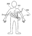
- FIG. 2 is a schematic diagram showing an aspect of use of the capsule endoscope system 100.
- the capsule endoscope 101 is placed in the body cavity of the subject 200.
- the portable terminal device 120 includes a wireless communication device 1, a main body 121, and a battery (not shown).
- the components of the wireless communication device 1 except the antenna 2 are accommodated in the main body 121.
- a battery (not shown) is attached to the main body 121.
- the main body 121 is attached to the outside of the subject 200.
- a plurality of antennas 2 are provided. Each of the plurality of antennas 2 is connected to the main body 121 via a signal line. When the capsule endoscope system 100 is used, the plurality of antennas 2 are arranged on the body surface of the subject 200.
- FIG. 3 is a functional block diagram illustrating a configuration of the wireless communication device 1.
- the signal processing unit 3 includes a demodulation unit 5, a signal detection unit 6, an image acquisition unit 7, and a display control unit 8.
- the demodulator 5 performs a process of restoring the radio signal received by the antenna 2 to a signal in a form that can be processed by the signal detector 6 and the image acquisition unit 7, and the restored signal is processed by the signal detector 6 and the image acquisition unit 7. Output to.
- the radio signal is restored as a signal encoded according to a predetermined rule.
- the signal restored by the demodulator 5 is also referred to as a radio signal.
- the signal detection unit 6 is configured to detect predetermined information from the radio signal received by the radio communication device 1 and output the detection result to the storage unit 4, the image acquisition unit 7, and the display control unit 8. ing.
- the storage unit 4 stores the detection result of the signal detection unit 6. The signal detector 6 will be described in detail later.
- the image acquisition unit 7 acquires image data generated by the imaging unit 112 (see FIG. 1) of the capsule endoscope 101 from wireless signals received by the wireless communication device 1, and stores the acquired image data. 4 and the display control unit 8 can be output.
- the storage unit 4 stores the image data acquired by the image acquisition unit 7.
- the image acquisition unit 7 can acquire image data based on the detection result of the signal detection unit 6. The operation of the image acquisition unit 7 will be described later.
- the display control unit 8 is configured to output information related to the detection result of the signal detection unit 6 and the image data acquired by the image acquisition unit 7 to the display unit 10. Further, the display control unit 8 can control the contents output to the display unit 10 based on the detection result of the signal detection unit 6. The operation of the display control unit 8 will be described later.
- the signal processing unit 3 further includes a clock generation unit (not shown).
- a clock generator (not shown) generates a processing clock having a predetermined frequency.
- the processing clock is input to a phase detector described later.
- each of the demodulation unit 5, the signal detection unit 6, the image acquisition unit 7, and the display control unit 8 may be configured as a separate electronic circuit.
- at least a part of the demodulation unit 5, the signal detection unit 6, the image acquisition unit 7, and the display control unit 8 may be configured as a circuit block in an integrated circuit such as an FPGA (Field Programmable Gate Array).
- the signal processing unit 3 includes at least one central processing unit (hereinafter referred to as a CPU), and the storage unit 4 includes a demodulation unit 5, a signal detection unit 6, an image acquisition unit 7, and a display control unit 8. You may memorize
- FIG. 4 is a functional block diagram showing the configuration of the signal detection unit 6.
- the signal detection unit 6 includes a phase detection unit 61, a vector generation unit 62, a vector synthesis unit 63, a calculation unit 64, and a determination unit 65 provided in this order from the demodulation unit 5 (see FIG. 3) side. Is included.
- the phase detection unit 61 receives a signal obtained by decoding the radio signal restored by the demodulation unit 5 and a processing clock. Further, the phase detector 61 is configured to read the symbol rate setting stored in the storage unit 4. The symbol rate setting is a predetermined symbol rate. In the present embodiment, the phase detector 61 detects the temporal position where the signal obtained by decoding the radio signal changes, detects the temporal position phase based on the symbol rate setting, and detects the detected phase. The data is output to the vector generation unit 62.
- a temporal position where the decoded signal changes is referred to as a signal change point.
- the decoded signal is a 1-bit signal represented by 0 and 1, for example.
- 0 is referred to as a low level signal and 1 is referred to as a high level signal.
- the temporal position at which the signal changes from the low level to the high level or from the high level to the low level is the signal change point.
- the vector generation unit 62 generates a vector corresponding to the phase detected by the phase detection unit 61 and having a predetermined size, and outputs the generated vector to the vector synthesis unit 63.
- the magnitude of the vector is, for example, 1.
- the vector combining unit 63 generates a combined vector by combining a plurality of vectors generated by the vector generating unit 62, and outputs the generated combined vector to the calculating unit 64.
- the combined vector is generated by combining a plurality of vectors generated based on a plurality of signal change points detected during a predetermined period in phase detector 61.
- phase detection unit 61 the vector generation unit 62, and the vector synthesis unit 63, that is, a method of generating a synthesized vector from a radio signal will be described in more detail later.
- the calculating unit 64 calculates a parameter having a correspondence relationship with the size of the combined vector generated by the vector combining unit 63, and outputs the calculated parameter to the determining unit 65.
- the parameter may be the size of the composite vector itself.
- the parameter may be an average value of the sizes of a plurality of vectors used when generating one composite vector. Since the average value of the sizes of the plurality of vectors is obtained by dividing the size of the combined vector by the number of vectors, it has a correspondence relationship with the size of the combined vector.
- the parameter may have a correspondence relationship with a component of the real number axis and a component corresponding to the imaginary number axis when the composite vector is represented by a complex number.
- the determination unit 65 determines whether the radio signal is a specific radio signal based on the parameter calculated by the calculation unit 64. Particularly in the present embodiment, the determination unit 65 determines whether the wireless signal is a specific wireless signal or noise by comparing the parameter with a predetermined threshold.
- the specific radio signal is a radio signal having a symbol rate that is the same as or substantially the same as the symbol rate setting input to phase detector 61.
- the wireless communication unit 113 see FIG. 1 of the capsule endoscope 101 transmits a wireless signal at the same symbol rate as the symbol rate setting, the specific wireless signal is transmitted to the capsule endoscope 101. Are wireless signals transmitted by the wireless communication unit 113.
- the determination unit 65 determines whether the reception state of a specific wireless signal is good or bad by comparing the parameter calculated by the calculation unit 64 with a predetermined threshold value.
- the determination result of whether or not the signal is a specific radio signal and the determination result of the reception state of the specific radio signal correspond to information detected from the radio signal.
- the determination unit 65 is configured to output these determination results as detection results of the signal detection unit 6 to the storage unit 4, the image acquisition unit 7, and the display control unit 8 (see FIG. 3). .
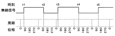
- FIG. 5 is an explanatory diagram illustrating an example of a radio signal and a phase.
- the signal changes from the low level to the high level at each of the times t1, t3, and t5
- the signal changes from the high level to the low level at each of the times t2 and t4.
- a plurality of sections drawn by dotted lines schematically represent a plurality of periods defined by the symbol rate setting, and the length of one section corresponds to one period.
- a period corresponding to five cycles is set as the predetermined period.
- the numbers given below the plurality of sections indicate the phases (units: degrees) of each of the plurality of periods.
- the phase at the start point is 0 ° and the phase at the end point is 360 °.
- the end point of the nth cycle (n is an integer of 1 to 4) coincides with the start point of the (n + 1) th cycle.
- the numeral indicating the phase of the start point that is, 0 is shown at the end point position.
- a broken straight line extending from the signal change point represents a temporal position of the signal change point.
- the temporal position of any one signal change point can be expressed as the temporal position or phase in any one period defined by the symbol rate setting.
- the phase detector 61 detects the time position of the signal change point in one cycle defined by the symbol rate setting as a phase.
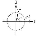
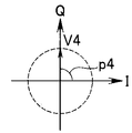
- FIGS. 6A to 6E are explanatory diagrams showing vectors generated from the phases shown in FIG.
- the vectors are represented by arrows.
- the length of the arrow represents the size of the vector.
- FIG. 6A shows a vector V1 generated from the phase p1 corresponding to the time t1 in FIG.
- FIG. 6B shows a vector V2 generated from phase p2 corresponding to time t2 in FIG.
- FIG. 6C shows a vector V3 generated from the phase p3 corresponding to time t3 in FIG.
- FIG. 6D shows a vector V4 generated from phase p4 corresponding to time t4 in FIG.
- FIG. 6E shows a vector V5 generated from the phase p5 corresponding to time t5 in FIG. 6A to 6E, the I axis corresponds to the real axis, and the Q axis corresponds to the imaginary axis.
- the vector generation unit 62 corresponds to the phase detected by the phase detection unit 61, for example, with the phase detected by the phase detection unit 61 as the vector declination angle with respect to the real number axis and the magnitude of the vector as 1.
- To generate a vector When the vector deflection angle is ⁇ and the vector size is 1, the vector real axis component is cos ⁇ , and the vector imaginary axis component is sin ⁇ .
- the vector may be expressed by a real axis component and an imaginary axis component.
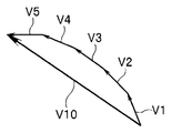
- FIG. 7 shows a combined vector V10 generated by combining the vectors V1 to V5 shown in FIGS. 6A to 6E.
- the vectors V1 to V5 and the combined vector V10 are respectively represented by arrows.
- the vectors V1 to V5 are drawn with arrows having the same length.
- the vector combining unit 63 combines the vectors V1 to V5 generated by the vector generating unit 62 during a predetermined period to generate a combined vector V10.
- the real axis components of the composite vector V10 are calculated by adding the real axis components of the vectors V1 to V5, and the imaginary axis components of the vectors V1 to V5 are added.
- the imaginary axis component of the composite vector V10 thereby calculating the composite vector V10.
- the case where five signal change points are detected during a predetermined period has been described as an example.
- the length of the predetermined period is arbitrary, and the number of signal change points detected during the predetermined period is also arbitrary.
- the number of detected signal change points may change depending on the mode of the radio signal.
- the number of vectors used to generate the composite vector can also change.
- the determination unit 65 calculates the size of the combined vector from the real axis component and the imaginary axis component of the combined vector.
- the determination unit 65 determines whether the wireless signal is a specific wireless signal by comparing the magnitude of the combined vector with a predetermined threshold. For example, when the magnitude of the combined vector is greater than or equal to a predetermined threshold, the determination unit 65 determines that the wireless signal is a specific wireless signal.
- the specific radio signal is a radio signal having the same or almost the same symbol rate as the symbol rate setting input to the phase detection unit 61.
- the determination unit 65 determines that the radio signal is not a specific radio signal. Particularly in the present embodiment, when the magnitude of the combined vector is less than a predetermined threshold, the determination unit 65 determines that the radio signal is noise.
- FIG. 8 shows vectors V1, V2, V3, V4, and V5 generated based on signal change points detected from a radio signal corresponding to a specific radio signal.
- the directions of the vectors V1 to V5 shown in FIG. 8 are different from the directions of the vectors V1 to V5 shown in FIGS. 6A to 6E and FIG.
- FIG. 9 shows a combined vector V10 generated by combining the vectors V1 to V5 shown in FIG.
- FIG. 10 shows vectors V11, V12, V13, V14, and V15 generated based on signal change points detected from a radio signal corresponding to noise.
- FIG. 11 shows a combined vector V110 generated by combining the vectors V11 to V15.
- the vectors are represented by arrows.
- the length of the arrow represents the size of the vector.
- the vectors V1 to V5 and V11 to V15 have the same magnitude. 8 to 11, the vectors V1 to V5 and V11 to V15 are drawn by arrows having the same length.
- the magnitude of the combined vector V110 generated by combining the vectors V11 to V15 is the vector V1 to V15. It becomes smaller than the size of the combined vector V10 generated by combining V5. In this way, by utilizing the property that the magnitude of the synthesized vector generated from noise is smaller than the magnitude of the synthesized vector generated from the specific radio signal, is the radio signal a specific radio signal? Whether it is noise or not can be determined.
- the parameter calculated by the calculation unit 64 is the size of the combined vector.
- the parameter is preferably a parameter that takes into account the number of detected signal change points.
- the determination unit 65 determines whether the radio signal is a specific radio signal as long as it is a parameter having a correspondence relationship with the size of the combined vector, not limited to the size of the combined vector itself or the average value. be able to.
- the determination unit 65 may determine whether the radio signal is a specific radio signal by comparing the real axis component and the imaginary axis component of the combined vector with predetermined threshold values.
- the radio signal may be determined to be a specific radio signal, or the real axis component and the imaginary axis component If both are greater than or equal to a predetermined threshold, the radio signal may be determined to be a specific radio signal.
- the determination unit 65 determines whether the reception state of a specific radio signal is good or bad as well as the above-described radio signal specification. That is, the determination unit 65 determines whether the reception state of a specific radio signal is good or bad by comparing the parameter calculated by the calculation unit 64 with a predetermined threshold value.
- a threshold value used when determining whether the reception state is good or bad is referred to as a threshold value (hereinafter referred to as the first threshold value) used when determining whether or not it is a specific radio signal.
- the first threshold value may be 20% and the second threshold value may be 60%.
- the determination unit 65 first determines whether or not the wireless signal is a specific wireless signal by comparing the parameter with the first threshold value. When the parameter is less than the first threshold (20%), the determination unit 65 determines that the received radio signal is not a specific radio signal.
- the determination unit 65 determines that the received wireless signal is a specific wireless signal. In this case, the determination unit 65 next determines whether the reception state is good or bad by comparing the parameter with the second threshold value. When the parameter is equal to or greater than the second threshold (60%), the determination unit 65 determines that the reception state is good. On the other hand, when the parameter is less than the second threshold, the determination unit 65 determines that the reception state is bad. As a case where the parameter is less than the second threshold and greater than or equal to the first threshold, for example, the jitter of the received specific radio signal may be large.
- a radio signal whose signal changes at a timing that matches or substantially matches the symbol rate setting, that is, a plurality of temporal positions of signal change points in one cycle defined by the symbol rate setting.
- Radio signals that coincide or substantially coincide with each other between the signal change points are determined as specific radio signals. Therefore, the symbol rate of the radio signal determined as a specific radio signal by the determination unit 65 basically matches or substantially matches the symbol rate setting.
- N is an integer of 2 or more
- the temporal position of the signal change point in one cycle defined by the symbol rate setting Are coincident between a plurality of signal change points. Therefore, it is preferable that the symbol rate setting matches the symbol rate of the specific radio signal to be received, that is, the radio signal transmitted by the radio communication unit 113 of the capsule endoscope 101.
- the image acquisition unit 7 receives the radio signal restored by the demodulation unit 5 and the detection result of the signal detection unit 6, that is, the determination result of the determination unit 65. Then, the image acquisition unit 7 acquires image data from the wireless signal determined by the determination unit 65 as a specific wireless signal. Further, the image acquisition unit 7 outputs the acquired image data to the storage unit 4 and the display control unit 8.
- the display control unit 8 receives the detection result of the signal detection unit 6, that is, the determination result of the determination unit 65 and the image data acquired by the image acquisition unit 7.
- the display control unit 8 causes the display unit 10 to display information corresponding to the determination result of the reception state among the determination results of the determination unit 65 and an image corresponding to the image data.
- the information and the image are configured to be simultaneously displayed on one screen of the display unit 10 by the display control unit 8, for example.
- the above information may be expressed by a numerical value or a predetermined index that varies depending on a determination result of whether the reception state is good or bad, or a parameter used for the determination (a parameter calculated by the calculation unit 64).
- the predetermined index there are, for example, a symbol such as ⁇ ⁇ , a color, and a pictogram such as a graph.
- the display control unit 8 may display images corresponding to all image data on the display unit 10, or select the content to be output to the display unit 10 based on the determination result of the reception state. May be. In the latter case, the display control unit 8 may cause the display unit 10 to display only an image corresponding to the image data of the wireless signal determined to have a good reception state. In this case, the image corresponding to the image data of the wireless signal determined to have a poor reception state is not displayed on the display unit 10.
- the detection result of the signal detection unit 6, that is, the determination result of the determination unit 65 and the image data acquired by the image acquisition unit 7 are input to the storage unit 4.
- the storage unit 4 stores the information corresponding to the determination result of the reception state among the determination results of the determination unit 65 and the image data in association with each other.
- the storage unit 4 may store all the image data, or may select the content to be stored based on the determination result of whether the reception state is good or bad. In the latter case, the storage unit 4 may store only the image data of the wireless signal determined to have a good reception state. In this case, the image data of the radio signal determined to have a poor reception state is discarded.
- the received radio signal is converted into a radio communication unit 113 of the capsule endoscope 101 by a series of processes in the phase detection unit 61, the vector generation unit 62, the vector synthesis unit 63, the calculation unit 64, and the determination unit 65. It is possible to determine whether or not the radio signal is transmitted (hereinafter also referred to as a transmission signal).
- the signal change point of the radio signal is detected as a phase, a vector corresponding to the phase is generated, a plurality of vectors are combined to generate a combined vector, and the size and correspondence of the generated combined vector Is calculated.
- the circuit scale can be reduced as compared with the case where the frequency component of the received radio signal is detected using DFT or FFT. From the above, according to the present embodiment, it is possible to specify a transmission signal without increasing the circuit scale.
- the determination unit 65 determines whether the reception state of a specific radio signal is good or bad by comparing the parameter with a predetermined threshold value.
- the user can be notified of the reception state, and the content displayed on the display unit 10 and the storage based on the determination result of the good / bad reception state as described above
- the contents stored in the unit 4 can be controlled.
- the image data of the radio signal determined to be bad is discarded in the storage unit 4. The amount of data stored can be reduced.
- the capsule endoscope 101 intermittently transmits wireless signals in order to reduce power consumption. While the capsule endoscope 101 is transmitting a wireless signal, the parameter calculated by the calculation unit 64 is equal to or greater than a predetermined threshold value, and while the capsule endoscope 101 is not transmitting a wireless signal. , The parameter becomes less than a predetermined threshold.
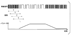
- FIG. 12 is an explanatory diagram schematically showing changes in parameters calculated by the calculation unit 64.
- a period T2 is a period in which the size of the parameter is equal to or greater than a predetermined threshold, and the capsule endoscope 101 is transmitting a radio signal.
- the periods T1 and T3 before and after the period T2 are periods in which the size of the parameter is less than a predetermined threshold, and the capsule endoscope 101 is not transmitting a radio signal. According to the present embodiment, it is possible to specify whether or not it is a period during which the capsule endoscope 101 is transmitting a radio signal based on the parameter.
- the capsule endoscope 101 is not transmitting a wireless signal, it is possible to temporarily stop the operation of at least one of the storage unit 4, the image acquisition unit 7, and the display control unit 8. . Thereby, according to this Embodiment, the power consumption of the radio
- the combined vector is generated by combining a plurality of vectors generated based on a plurality of signal change points detected during a predetermined period.
- the predetermined period is somewhat long, such as a period corresponding to a plurality of periods defined by the symbol rate setting. Note that whether or not the signal is a specific radio signal is determined in a preamble located at the head portion of the radio signal. Therefore, the predetermined period needs to be long enough to fit within the preamble period.
- FIG. 13 is a schematic diagram illustrating a first example of a signal change point detection period.
- FIG. 14 is a schematic diagram illustrating a second example of the signal change point detection period.
- FIG. 13 and FIG. 14 show an example of a radio signal and changes in parameters calculated based on the radio signal.
- an arrow with a symbol T represents a predetermined period for detecting a signal change point.
- FIG. 13 shows an example in which a plurality of periods T do not overlap each other.
- FIG. 14 shows an example in which a plurality of periods T overlap each other.
- the number of generated composite vectors is smaller than in the example shown in FIG. 14, and the phase detector 61, the vector generator 62, the vector combiner 63, the calculator 64, and the determiner
- the amount of processing in 65 can be reduced.
- the amount of the series of processes increases, but it becomes possible for the capsule endoscope 101 to recognize a transient state in which the parameter changes after starting to transmit a radio signal. As a result, the number of signals only for specifying the transmission signal can be reduced.
- the symbol rate setting is fixed to a predetermined value.
- the symbol rate setting may be changed according to time, for example.
- a signal detection unit 106 is provided instead of the signal detection unit 6 in the first embodiment.
- the signal detection unit 106 may detect predetermined information from the wireless signal received by the wireless communication device 1 and output the detection result to the storage unit 4, the image acquisition unit 7, and the display control unit 8 (see FIG. 3). It is configured to be able to.
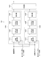
- FIG. 15 is a functional block diagram illustrating a configuration of the signal detection unit 106.
- the signal detection unit 106 includes a plurality of calculation units 106A and 106B and one determination unit 106C.
- the plurality of arithmetic units 106A and 106B are provided in parallel on the demodulator 5 (see FIG. 3) side.
- the determination unit 106C is provided at the subsequent stage of the plurality of calculation units 106A and 106B.
- the calculation unit 106A includes a phase detection unit 161A, a vector generation unit 162A, a vector synthesis unit 163A, and a calculation unit 164A provided in this order from the demodulation unit 5 (see FIG. 3) side.
- the functions of the phase detection unit 161A, the vector generation unit 162A, the vector synthesis unit 163A, and the calculation unit 164A are basically the same as the phase detection unit 61, the vector generation unit 62, the vector synthesis unit 63, and the calculation in the first embodiment.
- the function is the same as that of the unit 64.
- the calculation unit 106B includes a phase detection unit 161B, a vector generation unit 162B, a vector synthesis unit 163B, and a calculation unit 164B provided in this order from the demodulation unit 5 (see FIG. 3) side.
- the functions of the phase detection unit 161B, the vector generation unit 162B, the vector synthesis unit 163B, and the calculation unit 164B are basically the same as the phase detection unit 61, the vector generation unit 62, the vector synthesis unit 63, and the calculation in the first embodiment.
- the function of the unit 64 is the same.
- the phase detectors 161A and 161B are each configured to be able to read the symbol rate setting stored in the storage unit 4 (see FIG. 3).
- the symbol rate setting is different for each of the plurality of arithmetic units 106A and 106B. That is, in the present embodiment, the symbol rate setting read by phase detector 161A and the symbol rate setting read by phase detector 161B are different from each other.
- the symbol rate setting read by the phase detection unit 161A is referred to as a first symbol rate setting
- the symbol rate setting read by the phase detection unit 161B is referred to as a second symbol rate setting.
- the parameter calculated by the calculation unit 164A (hereinafter referred to as the first parameter) and the parameter calculated by the calculation unit 164B (hereinafter referred to as the second parameter) are input to the determination unit 106C.
- the determination unit 106C determines the symbol rate of the received radio signal based on the first and second parameters. This determination is performed using a predetermined threshold value. That is, the determination unit 106C determines the symbol rate of the radio signal by comparing each of the first and second parameters with a predetermined threshold value.
- the received radio signal is a radio signal having the same symbol rate as the first symbol rate setting. Is determined.
- the received radio signal is a radio signal having the same symbol rate as the second symbol rate setting. Is determined.
- the received radio signal has the smaller value of the first symbol rate setting and the second symbol rate setting. That is, it is determined that the radio signal has the same symbol rate as the slower one.
- both the first parameter and the second parameter are less than the predetermined threshold, it is determined that the received radio signal is noise.
- the symbol rate may be changed according to the state of the communication environment and the amount of image data.
- a plurality of arithmetic units 106A and 106B having different symbol rate settings are provided. Thereby, according to the present embodiment, even when the symbol rate of the radio signal is changed, the symbol rate of the radio signal is determined, and the received radio signal is transmitted to the capsule endoscope 101 by radio communication. It can be determined whether or not the wireless signal is transmitted by the unit 113.
- the first symbol rate setting is used.
- the temporal position of the signal change point in one defined cycle coincides between the signal change points. Therefore, it is preferable that the first symbol rate setting matches the symbol rate of the radio signal to be received, that is, the radio signal transmitted by the radio communication unit 113 of the capsule endoscope 101.
- the temporal position of the signal change point in one cycle defined by the second symbol rate setting is , And coincide between a plurality of signal change points.
- the second symbol rate setting is a symbol rate of a radio signal to be received, that is, a radio signal transmitted by the radio communication unit 113 of the capsule endoscope 101, and is different from the first symbol rate setting. It is preferable to match the symbol rate.
- the case where the number of the plurality of arithmetic units is two has been described as an example.
- the number of the plurality of calculation units is not limited to two and may be three or more.
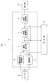
- FIG. 16 is a functional block diagram showing the configuration of the wireless communication apparatus according to this embodiment.
- FIG. 17 is a functional block diagram showing the configuration of the signal detection unit in the present embodiment. Similar to the first embodiment, the signal processing unit 3 includes a demodulation unit 5, a signal detection unit 6, an image acquisition unit 7, and a display control unit 8. As shown in FIG. 17, the configuration of the signal detection unit 6 is basically the same as that of the first embodiment.
- the signal processing unit 3 further includes a radio wave intensity acquisition unit 9.
- the radio wave intensity acquisition unit 9 acquires the radio wave intensity of the radio signal from the radio signal received by the antenna 2, and outputs the radio wave intensity information to the determination unit 65 of the signal detection unit 6.
- the radio wave intensity is represented by the magnitude of received power, for example.
- the determination unit 65 determines whether the reception state of a specific radio signal is good or bad based on the information on the radio field intensity acquired by the radio field intensity acquisition unit 9. Whether the reception state is good or bad is determined by comparing the magnitude of the radio wave intensity with a predetermined threshold (hereinafter referred to as a third threshold).
- a predetermined threshold hereinafter referred to as a third threshold.
- the threshold value used when the determination unit 65 determines whether or not it is a specific radio signal is defined as the first threshold value.
- the determination unit 65 first determines whether or not the radio signal is a specific radio signal by comparing the parameter calculated by the calculation unit 64 with the first threshold value. When the parameter is less than the first threshold, the determination unit 65 determines that the received wireless signal is not a specific wireless signal.
- the determination unit 65 determines that the received wireless signal is a specific wireless signal. In this case, the determination unit 65 next determines whether the reception state is good or bad by comparing the magnitude of the radio wave intensity with the third threshold value. When the magnitude of the radio wave intensity is equal to or greater than the third threshold, the determination unit 65 determines that the reception state is good. On the other hand, when the magnitude of the radio wave intensity is less than the third threshold, the determination unit 65 determines that the reception state is bad. For the determination, for example, information on the radio field intensity of the radio signal received immediately before is used.
- the radio communication apparatus 1 according to the second embodiment may be provided with the radio wave intensity acquisition unit 9 according to the third embodiment.
- the radio wave intensity acquisition unit 9 outputs the radio wave intensity information to the determination unit 106 ⁇ / b> C of the signal detection unit 106.
- the wireless communication device of the present invention may identify a wireless signal transmitted by a specific wireless transmission device from a plurality of wireless signals transmitted by a plurality of wireless transmission devices.
Landscapes
- Health & Medical Sciences (AREA)
- Life Sciences & Earth Sciences (AREA)
- Engineering & Computer Science (AREA)
- Surgery (AREA)
- Biomedical Technology (AREA)
- Molecular Biology (AREA)
- Pathology (AREA)
- Radiology & Medical Imaging (AREA)
- Nuclear Medicine, Radiotherapy & Molecular Imaging (AREA)
- Biophysics (AREA)
- Physics & Mathematics (AREA)
- Heart & Thoracic Surgery (AREA)
- Medical Informatics (AREA)
- Optics & Photonics (AREA)
- Animal Behavior & Ethology (AREA)
- General Health & Medical Sciences (AREA)
- Public Health (AREA)
- Veterinary Medicine (AREA)
- Computer Networks & Wireless Communication (AREA)
- Signal Processing (AREA)
- Multimedia (AREA)
- Endoscopes (AREA)
- Circuits Of Receivers In General (AREA)
Abstract
無線通信装置1は、受信した無線信号において復号した信号が変化する信号変化点を検出し、シンボルレート設定によって規定される1つの周期中の信号変化点の時間的な位置を位相として検出する位相検出部61と、検出した位相に対応し且つ所定の大きさを有するベクトルを生成するベクトル生成部62と、生成した複数のベクトルを合成して合成ベクトルを生成するベクトル合成部63と、生成した合成ベクトルの大きさと対応関係を有するパラメータを算出する算出部64と、算出したパラメータに基づいて無線信号が特定の無線信号であるか否かを判定する判定部65とを備えている。
Description
本発明は、無線信号を特定することができる無線通信装置およびカプセル型内視鏡システムに関する。
一般的に、医療分野において、内視鏡は、生体内の観察等の用途に用いられている。また、近年、内視鏡の一種として、被験者が嚥下することによって体内に導入されるカプセル型内視鏡が提案されている。カプセル型内視鏡は、蠕動運動に伴って体内を移動しながら体腔内の被写体を撮像して画像データを生成し、画像データを所定の規則に従って符号化して無線信号を生成し、無線信号を無線通信によって外部の受信装置に対して送信する。
カプセル型内視鏡は、内蔵されたバッテリによって駆動する。一般的に、カプセル型内視鏡では、バッテリの消費電力を低減するために、無線信号を間欠的に送信したり、通信環境の状態や画像データのデータ量に応じてシンボルレートを変更したりすることが行われる。そのため、受信装置では、無線信号の有無を検出したり、無線信号のシンボルレートを検出したりすることが必要である。
符号化された無線信号では、シンボルレートに応じて復号した信号が周期的に変化する。復号した信号が変化する点である信号変化点の時間的な位置は、位相によって表すことができる。信号変化点の位相の解析は、受信した無線信号を解析する手段として、一般的に用いられている。
位相は、例えばベクトルを用いて表すことができる。特開2005-318381号公報には、ベクトルを用いて位相中心を求めるゼロクロス検出回路が開示されている。
ところで、受信装置は、カプセル型内視鏡が送信した無線信号(以下、送信信号とも記す。)に限らず、ノイズ等の不要な無線信号を受信し得る。従って、受信装置は、不要な無線信号の中から送信信号を特定することが必要である。送信信号では、信号変化点の位相は一致する。従って、受信した無線信号の信号変化点の位相を解析することにより、送信信号を特定することができる。また、前述のように、位相は、ベクトルを用いて表すことができる。しかしながら、従来は、信号変化点の位相を表すベクトルを用いて、送信信号を特定することは行われていなかった。
なお、受信した無線信号を解析する手段としては、離散フーリエ変換(以下、DFTと記す。)や高速フーリエ変換(以下、FFTと記す。)を用いて、受信した無線信号の周波数成分を検出する方法がある。しかし、DFTやFFTを利用すると、回路規模が大きくなってしまうという問題がある。
そこで、本発明は、回路規模を大きくすることなく送信信号を特定することができる無線通信装置およびカプセル型内視鏡システムを提供することを目的とする。
本発明の一態様の無線通信装置は、受信した無線信号において復号した信号が変化する信号変化点を検出し、所定のシンボルレートによって規定される1つの周期中の前記信号変化点の時間的な位置を位相として検出する位相検出部と、前記位相に対応し且つ所定の大きさを有するベクトルを生成するベクトル生成部と、複数の前記ベクトルを合成して合成ベクトルを生成するベクトル合成部と、前記合成ベクトルの大きさと対応関係を有するパラメータを算出する算出部と、前記パラメータに基づいて前記無線信号が特定の無線信号であるか否かを判定する判定部とを備えている。
本発明の他の一態様の無線通信装置は、複数の演算部と1つの判定部とを備えた無線通信装置であって、前記複数の演算部の各々は、受信した無線信号において復号した信号が変化する信号変化点を検出し、所定のシンボルレートによって規定される1つの周期中の前記信号変化点の時間的な位置を位相として検出する位相検出部と、前記位相に対応し且つ所定の大きさを有するベクトルを生成するベクトル生成部と、複数の前記ベクトルを合成して合成ベクトルを生成するベクトル合成部と、前記合成ベクトルの大きさと対応関係を有するパラメータを算出する算出部とを有し、前記シンボルレートは、前記複数の演算部毎に異なっており、前記判定部は、前記複数の演算部の各々の前記算出部によって算出された複数の前記パラメータに基づいて、前記無線信号のシンボルレートを判定する。
本発明の一態様のカプセル型内視鏡システムは、被検体内を撮像して画像データを生成し、無線信号を用いて前記画像データを送信するカプセル型内視鏡と、無線通信装置とを備えている。
以下、図面を参照して、本発明の実施の形態を説明する。
[第1の実施の形態]
(内視鏡システムの構成)
始めに、本発明の第1の実施の形態に係わるカプセル型内視鏡システムの構成について説明する。図1は、本実施の形態に係わるカプセル型内視鏡システムの構成を示す説明図である。図1に示したように、カプセル型内視鏡システム100は、カプセル型内視鏡101と、本実施の形態に係わる無線通信装置1とを備えている。
(内視鏡システムの構成)
始めに、本発明の第1の実施の形態に係わるカプセル型内視鏡システムの構成について説明する。図1は、本実施の形態に係わるカプセル型内視鏡システムの構成を示す説明図である。図1に示したように、カプセル型内視鏡システム100は、カプセル型内視鏡101と、本実施の形態に係わる無線通信装置1とを備えている。
カプセル型内視鏡101は、被検者の体腔内に配置可能な寸法および形状を有しており、被検者が嚥下することにより消化器管腔に導入される。また、カプセル型内視鏡101は、被検体内を撮像して画像データを生成し、無線信号を用いて画像データを送信することができるように構成されている。本実施の形態では、カプセル型内視鏡101は、照明部111と、撮像部112と、無線通信部113と、記憶部114と、電源部115と、制御部116と、筐体117とを備えている。筐体117は、細長いカプセル状の形状を有している。筐体117を除くカプセル型内視鏡101の構成要素は、筐体117内に密封されている。
照明部111は、LED等の発光素子を含んでおり、被検体内の被写体を照明するための照明光を発生する。撮像部112は、CCD等の撮像素子を含んでおり、照明部111により照明された被写体を撮像し、画像データを生成する。
無線通信部113は、符号化変調部とアンテナを含んでおり、所定の規則に従って符号化された無線信号を送信する。図1において、破線の矢印は、無線信号を表している。無線信号は、先頭部分に位置するプリアンブルと、プリアンブルに続く主データとによって構成される。本実施の形態では、主データは、撮像部112が生成した画像データである。
なお、無線通信部113は、無線信号を送信する機能に限らず、無線通信装置1が送信した無線信号を受信する機能を有していてもよい。この場合、無線通信部113には、受信した無線信号から情報を復元する復調部が設けられる。
記憶部114は、例えばRAM等のメモリよりなり、撮像部112が生成した画像データを記憶することができるように構成されている。電源部115は、例えばバッテリよりなり、カプセル型内視鏡101の各部に駆動電力を供給することができるように構成されている。制御部116は、カプセル型内視鏡101の各部の動作を制御する。
無線通信装置1は、カプセル型内視鏡101に対して物理的に分離されている。なお、無線通信装置1は、例えばワークステーションのような据え置き型の装置の一部であってもよいし、バッテリによって駆動する携帯型端末装置の一部であってもよい。
本実施の形態では、無線通信装置1は、アンテナ2と、信号処理部3と、記憶部4とを備えている。アンテナ2は、カプセル型内視鏡101の無線通信部113が送信した無線信号を受信する。信号処理部3は、受信した無線信号に対して所定の処理を行う。所定の処理には、無線信号に含まれる画像データを取得する処理が含まれる。信号処理部3の構成については、後で詳しく説明する。
記憶部4は、取得した画像データと、後述する信号検出部の検出結果およびシンボルレート設定を記憶することができるように構成されている。記憶部4は、RAM等の揮発性のメモリによって構成されていてもよいし、フラッシュメモリまたは磁気ディスク装置等の書き換え可能な不揮発性のメモリによって構成されていてもよい。
カプセル型内視鏡システム100は、更に、表示部10を備えていてもよい。表示部10は、例えば、LCD等の表示装置によって構成されている。表示部10は、無線通信装置1の信号処理部3が取得した画像データに対応する画像を表示する。図1には、表示部10が無線通信装置1に直接接続されている例を示している。
ここで、無線通信装置1が携帯型端末装置120の一部である場合を例にとって、カプセル型内視鏡システム100の使用の態様について説明する。図2は、カプセル型内視鏡システム100の使用の態様を示す模式図である。カプセル型内視鏡システム100の使用時には、カプセル型内視鏡101は、被検者200の体腔内に配置される。
携帯型端末装置120は、無線通信装置1と、本体部121と、図示しないバッテリとを備えている。アンテナ2を除く無線通信装置1の構成要素は、本体部121に収容されている。図示しないバッテリは、本体部121に装着される。カプセル型内視鏡システム100の使用時には、本体部121は、被検者200の体外に装着される。
図2に示した例では、アンテナ2が複数設けられている。複数のアンテナ2の各々は、信号線を介して本体部121に接続されている。カプセル型内視鏡システム100の使用時には、複数のアンテナ2は、被検者200の体表部に配置される。
(信号処理部の構成)
次に、図3を参照して、信号処理部3の構成について説明する。図3は、無線通信装置1の構成を示す機能ブロック図である。図3に示したように、信号処理部3は、復調部5と、信号検出部6と、画像取得部7と、表示制御部8とを含んでいる。
次に、図3を参照して、信号処理部3の構成について説明する。図3は、無線通信装置1の構成を示す機能ブロック図である。図3に示したように、信号処理部3は、復調部5と、信号検出部6と、画像取得部7と、表示制御部8とを含んでいる。
復調部5は、アンテナ2が受信した無線信号を、信号検出部6と画像取得部7において処理可能な形態の信号に復元する処理を行い、復元した信号を信号検出部6と画像取得部7に出力する。本実施の形態では、無線信号は、所定の規則に従って符号化された信号として復元される。以下の説明では、便宜上、復調部5によって復元された信号も無線信号と言う。
信号検出部6は、無線通信装置1が受信した無線信号から所定の情報を検出し、その検出結果を記憶部4、画像取得部7および表示制御部8に出力することができるように構成されている。記憶部4は、信号検出部6の検出結果を記憶する。信号検出部6については、後で詳しく説明する。
画像取得部7は、無線通信装置1が受信した無線信号の中から、カプセル型内視鏡101の撮像部112(図1参照)が生成した画像データを取得し、取得した画像データを記憶部4と表示制御部8に出力することができるように構成されている。記憶部4は、画像取得部7が取得した画像データを記憶する。本実施の形態では、画像取得部7は、信号検出部6の検出結果に基づいて、画像データを取得することができる。画像取得部7の動作については、後で説明する。
表示制御部8は、信号検出部6の検出結果に関する情報と画像取得部7が取得した画像データを表示部10に出力することができるように構成されている。また、表示制御部8は、信号検出部6の検出結果に基づいて、表示部10に出力する内容を制御することができる。表示制御部8の動作については、後で説明する。
信号処理部3は、更に、図示しないクロック発生部を含んでいる。図示しないクロック発生部は、所定の周波数の処理クロックを発生する。処理クロックは、後述する位相検出部に入力される。
なお、本実施の形態では、復調部5、信号検出部6、画像取得部7および表示制御部8の各々は、別個の電子回路として構成されていてもよい。あるいは、復調部5、信号検出部6、画像取得部7および表示制御部8の少なくとも一部は、FPGA(Field Programmable Gate Array)等の集積回路における回路ブロックとして構成されていてもよい。あるいは、信号処理部3は、少なくとも1つの中央演算処理装置(以下、CPUと記す。)を備え、記憶部4は、復調部5、信号検出部6、画像取得部7および表示制御部8の少なくとも一部の機能を実現するプログラムを記憶しておいてもよい。この場合、CPUが記憶部4からプログラムを読み出して実行することにより、復調部5、信号検出部6、画像取得部7および表示制御部8の少なくとも一部の機能が実現される。
(信号検出部の構成)
次に、図4を参照して、信号検出部6の構成について説明する。図4は、信号検出部6の構成を示す機能ブロック図である。図4に示したように、信号検出部6は、復調部5(図3参照)側から順に設けられた位相検出部61、ベクトル生成部62、ベクトル合成部63、算出部64および判定部65を含んでいる。
次に、図4を参照して、信号検出部6の構成について説明する。図4は、信号検出部6の構成を示す機能ブロック図である。図4に示したように、信号検出部6は、復調部5(図3参照)側から順に設けられた位相検出部61、ベクトル生成部62、ベクトル合成部63、算出部64および判定部65を含んでいる。
位相検出部61には、復調部5によって復元された無線信号を復号した信号と、処理クロックが入力される。また、位相検出部61は、記憶部4に記憶されたシンボルレート設定を読み出すことができるように構成されている。なお、シンボルレート設定とは、シンボルレートの所定値である。本実施の形態では、位相検出部61は、無線信号を復号した信号が変化する時間的な位置を検出すると共に、シンボルレート設定に基づいて時間的な位置の位相を検出し、検出した位相をベクトル生成部62に出力する。以下、復号した信号が変化する時間的な位置を、信号変化点と言う。
なお、復号した信号は、例えば、0と1で表現される1bitの信号である。ここで、0をローレベルの信号と言い、1をハイレベルの信号と言う。この場合、信号がローレベルからハイレベルまたはハイレベルからローレベルに変化する時間的な位置が、信号変化点となる。
ベクトル生成部62は、位相検出部61が検出した位相に対応し、且つ所定の大きさを有するベクトルを生成し、生成したベクトルをベクトル合成部63に出力する。ベクトルの大きさは、例えば1である。
ベクトル合成部63は、ベクトル生成部62が生成した複数のベクトルを合成して合成ベクトルを生成し、生成した合成ベクトルを算出部64に出力する。本実施の形態では、合成ベクトルは、位相検出部61において所定の期間中に検出された複数の信号変化点に基づいて生成された複数のベクトルを合成して生成される。
位相検出部61、ベクトル生成部62およびベクトル合成部63における一連の処理、すなわち無線信号から合成ベクトルを生成する方法については、後で更に詳しく説明する。
算出部64は、ベクトル合成部63で生成された合成ベクトルの大きさと対応関係を有するパラメータを算出し、算出したパラメータを判定部65に出力する。パラメータは、合成ベクトルの大きさそのものであってもよい。あるいは、パラメータは、1つの合成ベクトルを生成する際に用いられた複数のベクトルの大きさの平均値であってもよい。複数のベクトルの大きさの平均値は、合成ベクトルの大きさをベクトルの数で割ることによって得られることから、合成ベクトルの大きさと対応関係を有している。あるいは、パラメータは、合成ベクトルを複素数で表したときの実数軸の成分および虚数軸に対応する成分と対応関係を有するものであってもよい。
判定部65は、算出部64が算出したパラメータに基づいて、無線信号が特定の無線信号であるか否かを判定する。本実施の形態では特に、判定部65は、パラメータと所定の閾値とを比較することによって、無線信号が特定の無線信号であるかノイズであるかを判定する。本実施の形態では、特定の無線信号は、位相検出部61に入力されるシンボルレート設定と同じかほぼ同じシンボルレートを有する無線信号である。特に、カプセル型内視鏡101の無線通信部113(図1参照)が、上記シンボルレート設定と同じシンボルレートで無線信号を送信した場合には、特定の無線信号は、カプセル型内視鏡101の無線通信部113が送信した無線信号である。
また、判定部65は、算出部64が算出したパラメータと所定の閾値とを比較することによって、特定の無線信号の受信状態の善し悪しを判定する。特定の無線信号であるか否かの判定結果と、特定の無線信号の受信状態の判定結果は、無線信号から検出された情報に対応する。判定部65は、これらの判定結果を、信号検出部6の検出結果として、記憶部4、画像取得部7および表示制御部8(図3参照)に出力することができるように構成されている。
(合成ベクトルの生成方法)
次に、無線信号から合成ベクトルを生成する方法について詳しく説明する。ここでは、所定の期間中に5つの信号変化点が検出された場合を例にとって説明する。始めに、図5を参照して、位相検出部61における位相の検出方法について説明する。図5は、無線信号と位相の一例を示す説明図である。図5に示した例では、時刻t1,t3,t5の各々において、信号がローレベルからハイレベルに変化し、時刻t2,t4の各々において、信号がハイレベルからローレベルに変化している。
次に、無線信号から合成ベクトルを生成する方法について詳しく説明する。ここでは、所定の期間中に5つの信号変化点が検出された場合を例にとって説明する。始めに、図5を参照して、位相検出部61における位相の検出方法について説明する。図5は、無線信号と位相の一例を示す説明図である。図5に示した例では、時刻t1,t3,t5の各々において、信号がローレベルからハイレベルに変化し、時刻t2,t4の各々において、信号がハイレベルからローレベルに変化している。
図5において、点線で描いた複数の区画は、シンボルレート設定によって規定される複数の周期を模式的に表しており、1つの区画の長さが1周期に対応する。ここでは、5周期に相当する期間を、前記の所定の期間とする。また、複数の区画の下方に付した数字は、複数の周期の各々の位相(単位は°)を示している。複数の周期の各々において、始点の位相は0°であり、終点の位相は360°である。なお、n番目(nは1以上4以下の整数)の周期の終点は、n+1番目の周期の始点に一致する。図5では、便宜上、終点の位置では、始点の位相を示す数字すなわち0のみを示している。
また、図5において、信号変化点から延出した破線の直線は、その信号変化点の時間的な位置を表している。図5に示したように、任意の1つの信号変化点の時間的な位置は、シンボルレート設定によって規定される任意の1つの周期中の時間的な位置すなわち位相として表すことができる。位相検出部61は、シンボルレート設定によって規定される1つの周期中の信号変化点の時間的な位置を、位相として検出する。
次に、図6Aないし図6Eを参照して、ベクトル生成部62におけるベクトルの生成方法について説明する。図6Aないし図6Eは、図5に示した位相から生成されたベクトルを示す説明図である。図6Aないし図6Eでは、ベクトルを矢印で表している。矢印の長さは、ベクトルの大きさを表している。図6Aは、図5における時刻t1に対応する位相p1から生成されたベクトルV1を示している。図6Bは、図5における時刻t2に対応する位相p2から生成されたベクトルV2を示している。図6Cは、図5における時刻t3に対応する位相p3から生成されたベクトルV3を示している。図6Dは、図5における時刻t4に対応する位相p4から生成されたベクトルV4を示している。図6Eは、図5における時刻t5に対応する位相p5から生成されたベクトルV5を示している。また、図6Aないし図6Eにおいて、I軸は実数軸に対応し、Q軸は虚数軸に対応する。
ベクトル生成部62は、例えば、位相検出部61によって検出された位相を、実数軸を基準としたベクトルの偏角とし、ベクトルの大きさを1として、位相検出部61によって検出された位相に対応するベクトルを生成する。なお、ベクトルの偏角をθとし、ベクトルの大きさを1とした場合、ベクトルの実数軸の成分はcosθとなり、ベクトルの虚数軸の成分はsinθとなる。本実施の形態では、ベクトルを、実数軸の成分と虚数軸の成分で表してもよい。
次に、図7を参照して、ベクトル合成部63におけるベクトルの合成方法について説明する。図7は、図6Aないし図6Eに示したベクトルV1~V5を合成して生成された合成ベクトルV10を示している。図7では、図6Aないし図6Eと同様に、ベクトルV1~V5および合成ベクトルV10をそれぞれ矢印で表している。なお、図6Aないし図6Eおよび図7では、ベクトルV1~V5を、同じ長さの矢印で描いている。
ベクトル合成部63は、所定の期間中にベクトル生成部62が生成したベクトルV1~V5を合成して合成ベクトルV10を生成する。具体的には、例えば、ベクトルV1~V5の各々の実数軸の成分を加算することによって合成ベクトルV10の実数軸の成分を算出し、ベクトルV1~V5の各々の虚数軸の成分を加算することによって合成ベクトルV10の虚数軸の成分を算出し、これにより、合成ベクトルV10を算出する。
なお、ここまでは、所定の期間中に5つの信号変化点が検出された場合を例にとって説明してきた。しかし、所定の期間の長さは任意であり、所定の期間中に検出される信号変化点の数も任意である。また、信号変化点を検出する期間を固定した場合、無線信号の態様に応じて、検出される信号変化点の数は変化し得る。そのため、この場合には、合成ベクトルを生成するのに用いられるベクトルの数も変化し得る。
(判定部における判定方法)
次に、判定部65における判定方法について説明する。ここでは、算出部64によって算出されるパラメータが合成ベクトルの大きさそのものである場合を例にとって説明する。算出部64は、例えば、合成ベクトルの実数軸の成分と虚数軸の成分から、合成ベクトルの大きさを算出する。
次に、判定部65における判定方法について説明する。ここでは、算出部64によって算出されるパラメータが合成ベクトルの大きさそのものである場合を例にとって説明する。算出部64は、例えば、合成ベクトルの実数軸の成分と虚数軸の成分から、合成ベクトルの大きさを算出する。
判定部65は、合成ベクトルの大きさと所定の閾値とを比較することによって、無線信号が特定の無線信号であるか否かを判定する。例えば、合成ベクトルの大きさが所定の閾値以上の場合、判定部65は、無線信号が特定の無線信号であると判定する。前述のように、本実施の形態では、特定の無線信号は、位相検出部61に入力されるシンボルレート設定と同じかほぼ同じシンボルレートを有する無線信号である。
一方、合成ベクトルの大きさが所定の閾値未満の場合、判定部65は、無線信号が特定の無線信号ではないと判定する。本実施の形態では特に、合成ベクトルの大きさが所定の閾値未満の場合、判定部65は、無線信号がノイズであると判定する。
以下、図8ないし図11を参照して、合成ベクトルの大きさによって、特定の無線信号であるかノイズであるかを判定することができる理由について説明する。図8は、特定の無線信号に相当する無線信号から検出された信号変化点に基づいて生成されたベクトルV1,V2,V3,V4,V5を示している。なお、便宜上、図8に示したベクトルV1~V5の方向を、図6Aないし図6Eおよび図7に示したベクトルV1~V5の方向と異ならせている。図9は、図8に示したベクトルV1~V5を合成して生成された合成ベクトルV10を示している。図10は、ノイズに相当する無線信号から検出された信号変化点に基づいて生成されたベクトルV11,V12,V13,V14,V15を示している。図11は、ベクトルV11~V15を合成して生成された合成ベクトルV110を示している。
図8ないし図11では、ベクトルを矢印で表している。矢印の長さは、ベクトルの大きさを表している。ベクトルV1~V5,V11~V15の大きさは、互いに等しいものとする。図8ないし図11では、ベクトルV1~V5,V11~V15を、同じ長さの矢印で描いている。
図8に示したように、特定の無線信号に相当する無線信号から検出された複数の信号変化点に基づいてベクトルV1~V5を生成すると、ベクトルV1~V5の各々の方向はある程度一致する。これは、特定の無線信号では、シンボルレート設定にほぼ合致したタイミングで信号が変化しており、シンボルレート設定によって規定される1つの周期中の信号変化点の時間的な位置が、複数の信号変化点の間でほぼ一致し、その結果、位相も複数の信号変化点の間でほぼ一致するからである。
これに対し、図10に示したように、ノイズに相当する無線信号から検出された複数の信号変化点に基づいてベクトルV11~V15を生成すると、ベクトルV11~V15の各々の方向はランダムになる。これは、ノイズでは、ランダムに信号が変化しており、シンボルレート設定によって規定される1つの周期中の信号変化点の時間的な位置が、複数の信号変化点の間でランダムに変化し、その結果、位相も複数の信号変化点の間でランダムに変化するからである。
このように、ベクトルV11~V15の方向がランダムになることから、図9および図11に示したように、ベクトルV11~V15を合成して生成された合成ベクトルV110の大きさは、ベクトルV1~V5を合成して生成された合成ベクトルV10の大きさよりも小さくなる。このように、ノイズから生成された合成ベクトルの大きさは、特定の無線信号から生成された合成ベクトルの大きさよりも小さくなるという性質を利用することにより、無線信号が特定の無線信号であるかノイズであるかを判定することができる。
ここまでは、算出部64によって算出されたパラメータが合成ベクトルの大きさそのものである場合を例にとって説明してきた。前述のように、信号変化点を検出する期間を固定した場合、無線信号の態様に応じて、検出される信号変化点の数は変化し得る。従って、パラメータとしては、検出される信号変化点の数を考慮したパラメータであることが好ましい。このようなパラメータとしては、1つの合成ベクトルを生成する際に用いられた複数のベクトルの大きさの平均値がある。
また、判定部65は、合成ベクトルの大きさそのものまたは上記平均値に限らず、合成ベクトルの大きさと対応関係を有するパラメータであれば、無線信号が特定の無線信号であるか否かを判定することができる。例えば、判定部65は、合成ベクトルの実数軸の成分と虚数軸の成分を、それぞれ所定の閾値と比較することによって、無線信号が特定の無線信号であるか否かを判定してもよい。この場合、実数軸の成分と虚数軸の成分の一方が所定の閾値以上の場合に、無線信号が特定の無線信号であると判定してもよいし、実数軸の成分と虚数軸の成分の両方が所定の閾値以上の場合に、無線信号が特定の無線信号であると判定してもよい。
また、本実施の形態では、判定部65は、上述のような無線信号の特定に限らず、特定の無線信号の受信状態の善し悪しを判定する。すなわち、判定部65は、算出部64によって算出されたパラメータと所定の閾値とを比較することによって、特定の無線信号の受信状態の良し悪しを判定する。
なお、受信状態の良し悪しを判定する際に用いられる閾値(以下、第2の閾値と言う。)は、特定の無線信号であるか否かを判定する際に用いられる閾値(以下、第1の閾値と言う。)と同じでもよいし、異なっていてもよい。例えば、複数のベクトルの方向が完全に一致したときに算出されるパラメータの大きさを100%とした場合、第1の閾値は20%とし、第2の閾値は60%としてもよい。この場合、判定部65は、まず、パラメータと第1の閾値とを比較することによって、無線信号が特定の無線信号であるか否かを判定する。パラメータが第1の閾値(20%)未満である場合、判定部65は、受信した無線信号が特定の無線信号ではないと判定する。
パラメータが第1の閾値以上である場合、判定部65は、受信した無線信号が特定の無線信号であると判定する。この場合、判定部65は、次に、パラメータと第2の閾値とを比較することによって、受信状態の善し悪しを判定する。パラメータが第2の閾値(60%)以上の場合、判定部65は、受信状態が良いと判定する。一方、パラメータが第2の閾値未満の場合、判定部65は、受信状態が悪いと判定する。パラメータが第2の閾値未満第1の閾値以上になる場合としては、例えば、受信した特定の無線信号のジッタが大きい場合がある。
ところで、本実施の形態では、シンボルレート設定に合致またはほぼ合致したタイミングで信号が変化する無線信号、すなわちシンボルレート設定によって規定される1つの周期中の信号変化点の時間的な位置が、複数の信号変化点の間で一致またはほぼ一致する無線信号を、特定の無線信号として判定している。従って、判定部65によって特定の無線信号と判定された無線信号のシンボルレートは、基本的には、シンボルレート設定と一致するかほぼ一致する。ただし、シンボルレート設定の1/N倍(Nは2以上の整数)のシンボルレートを有する無線信号の場合にも、シンボルレート設定によって規定される1つの周期中の信号変化点の時間的な位置は、複数の信号変化点の間で一致する。従って、シンボルレート設定は、受信しようとする特定の無線信号、すなわちカプセル型内視鏡101の無線通信部113が送信した無線信号のシンボルレートに一致させておくことが好ましい。
(画像取得部、表示制御部および記憶部の動作)
次に、図3および図4を参照して、画像取得部7、表示制御部8および記憶部4の動作について説明する。始めに、画像取得部7の動作について説明する。画像取得部7には、復調部5によって復元された無線信号と、信号検出部6の検出結果すなわち判定部65の判定結果が入力される。そして、画像取得部7は、判定部65によって特定の無線信号と判定された無線信号から、画像データを取得する。また、画像取得部7は、取得した画像データを記憶部4と表示制御部8に出力する。
次に、図3および図4を参照して、画像取得部7、表示制御部8および記憶部4の動作について説明する。始めに、画像取得部7の動作について説明する。画像取得部7には、復調部5によって復元された無線信号と、信号検出部6の検出結果すなわち判定部65の判定結果が入力される。そして、画像取得部7は、判定部65によって特定の無線信号と判定された無線信号から、画像データを取得する。また、画像取得部7は、取得した画像データを記憶部4と表示制御部8に出力する。
次に、表示制御部8の動作について説明する。表示制御部8には、信号検出部6の検出結果すなわち判定部65の判定結果と、画像取得部7によって取得された画像データが入力される。表示制御部8は、判定部65の判定結果のうち受信状態の良し悪しの判定結果に対応する情報と、画像データに対応する画像とを、表示部10に表示させる。上記の情報および画像は、例えば、表示制御部8によって、表示部10の1画面上に同時に表示されるように構成される。上記の情報は、受信状態の良し悪しの判定結果や、判定に用いたパラメータ(算出部64によって算出されたパラメータ)によって変化する数字または所定の指標によって表してもよい。所定の指標としては、例えば、○×等の記号や、色や、グラフ等のピクトグラムがある。
また、表示制御部8は、全ての画像データに対応する画像を表示部10に表示させてもよいし、受信状態の良し悪しの判定結果に基づいて、表示部10に出力する内容を選択してもよい。後者の場合、表示制御部8は、受信状態が良いと判定された無線信号の画像データに対応する画像のみを表示部10に表示させてもよい。この場合、受信状態が悪いと判定された無線信号の画像データに対応する画像は、表示部10には表示されない。
次に、記憶部4の動作について説明する。記憶部4には、信号検出部6の検出結果すなわち判定部65の判定結果と、画像取得部7によって取得された画像データが入力される。記憶部4は、判定部65の判定結果のうち受信状態の良し悪しの判定結果に対応する情報と、画像データとを、関連付けて記憶する。
なお、記憶部4は、全ての画像データを記憶してもよいし、受信状態の良し悪しの判定結果に基づいて、記憶する内容を選択してもよい。後者の場合、記憶部4は、受信状態が良いと判定された無線信号の画像データのみを記憶してもよい。この場合、受信状態が悪いと判定された無線信号の画像データは破棄される。
(作用および効果)
次に、本実施の形態に係わる無線通信装置1およびカプセル型内視鏡システム100の作用および効果について説明する。本実施の形態では、位相検出部61、ベクトル生成部62、ベクトル合成部63、算出部64および判定部65における一連の処理によって、受信した無線信号がカプセル型内視鏡101の無線通信部113が送信した無線信号(以下、送信信号とも記す。)であるか否かを判定することができる。上記一連の処理では、無線信号の信号変化点を位相として検出し、位相に対応するベクトルを生成し、複数のベクトルを合成して合成ベクトルを生成し、生成された合成ベクトルの大きさと対応関係を有するパラメータを算出している。この一連の処理に用いられる演算は、DFTやFFTの演算に比べて簡単である。従って、本実施の形態によれば、DFTやFFTを利用して受信した無線信号の周波数成分を検出する場合に比べて、回路規模を小さくすることができる。以上のことから、本実施の形態によれば、回路規模を大きくすることなく送信信号を特定することができる。
次に、本実施の形態に係わる無線通信装置1およびカプセル型内視鏡システム100の作用および効果について説明する。本実施の形態では、位相検出部61、ベクトル生成部62、ベクトル合成部63、算出部64および判定部65における一連の処理によって、受信した無線信号がカプセル型内視鏡101の無線通信部113が送信した無線信号(以下、送信信号とも記す。)であるか否かを判定することができる。上記一連の処理では、無線信号の信号変化点を位相として検出し、位相に対応するベクトルを生成し、複数のベクトルを合成して合成ベクトルを生成し、生成された合成ベクトルの大きさと対応関係を有するパラメータを算出している。この一連の処理に用いられる演算は、DFTやFFTの演算に比べて簡単である。従って、本実施の形態によれば、DFTやFFTを利用して受信した無線信号の周波数成分を検出する場合に比べて、回路規模を小さくすることができる。以上のことから、本実施の形態によれば、回路規模を大きくすることなく送信信号を特定することができる。
なお、一般的に、DFTやFFTを利用して受信した無線信号の周波数成分を検出する回路では、受信しようとする無線信号のシンボルレートの整数倍という比較的速い動作クロックで回路を動作させる必要がある。これに対し、本実施の形態では、上記の要件は必要ない。従って、本実施の形態では、比較的遅い動作クロックを設定可能である。
また、本実施の形態では、判定部65は、パラメータと所定の閾値とを比較することによって、特定の無線信号の受信状態の良し悪しを判定している。これにより、本実施の形態によれば、受信状態を使用者に知らせることができると共に、前述のように、受信状態の良し悪しの判定結果に基づいて、表示部10に表示する内容や、記憶部4に記憶する内容を制御することができる。特に、受信状態の良し悪しの判定結果に基づいて記憶部4に記憶する内容を制御する場合には、受信状態が悪いと判定された無線信号の画像データを破棄することによって、記憶部4に記憶されるデータ量を少なくすることができる。
また、カプセル型内視鏡101では、消費電力を低減するために、無線信号を間欠的に送信する。カプセル型内視鏡101が無線信号を送信している間は、算出部64によって算出されるパラメータは、所定の閾値以上になり、カプセル型内視鏡101が無線信号を送信していない間は、パラメータは、所定の閾値未満になる。
図12は、算出部64によって算出されるパラメータの変化を模式的に示す説明図である。図12において、期間T2は、パラメータの大きさが所定の閾値以上の期間であり、カプセル型内視鏡101が無線信号を送信している期間である。期間T2の前後の期間T1,T3は、パラメータの大きさが所定の閾値未満の期間であり、カプセル型内視鏡101が無線信号を送信していない期間である。本実施の形態によれば、パラメータに基づいて、カプセル型内視鏡101が無線信号を送信している期間であるか否かを特定することができる。
なお、カプセル型内視鏡101が無線信号を送信していない期間では、記憶部4、画像取得部7および表示制御部8のうちの少なくとも1つの動作を一時的に停止することが可能である。これにより、本実施の形態によれば、無線通信装置1の消費電力を低減することができる。
また、本実施の形態では、合成ベクトルは、所定の期間中に検出された複数の信号変化点に基づいて生成された複数のベクトルを合成して生成される。判定部65における判定精度を高める観点から、所定の期間は、シンボルレート設定によって規定される複数の周期に相当する期間にする等、ある程度長いことが好ましい。なお、特定の無線信号であるか否かの判定は、無線信号の先頭部分に位置するプリアンブルにおいて行われる。従って、所定の期間は、プリアンブルの期間に収まるような長さであることが必要である。
また、本実施の形態では、信号変化点を検出する所定の期間として複数の期間が設定され、合成ベクトルが逐次生成される。すなわち、複数の期間にわたって、複数の合成ベクトルが生成される。複数の期間の各々は、互いに重なっていなくてもよいし、互いに重なっていてもよい。図13は、信号変化点の検出期間の第1の例を示す模式図である。図14は、信号変化点の検出期間の第2の例を示す模式図である。図13および図14には、無線信号の一例と、この無線信号に基づいて算出されたパラメータの変化を示している。また、図13および図14において、記号Tを付した矢印は、信号変化点を検出する所定の期間を表している。図13は、複数の期間Tが互いに重なっていない例を示している。図14は、複数の期間Tが互いに重なっている例を示している。
図13に示した例では、図14に示した例に比べて、生成される合成ベクトルの数が少なくなり、位相検出部61、ベクトル生成部62、ベクトル合成部63、算出部64および判定部65における一連の処理の量を少なくすることができる。一方、図14に示した例では、上記一連の処理の量は増加するが、カプセル型内視鏡101が無線信号の送信を開始してパラメータが変化する過渡状態を認識することが可能になり、その結果、送信信号を特定するためだけの信号を少なくすることができる。
なお、本実施の形態では、シンボルレート設定は、所定の値に固定される。しかし、シンボルレート設定は、例えば時間に応じて変化させてもよい。
[第2の実施の形態]
次に、本発明の第2の実施の形態について説明する。本実施の形態に係わる無線通信装置1の構成は、以下の点で第1の実施の形態と異なっている。本実施の形態では、第1の実施の形態における信号検出部6の代わりに、信号検出部106が設けられている。信号検出部106は、無線通信装置1が受信した無線信号から所定の情報を検出し、その検出結果を記憶部4、画像取得部7および表示制御部8(図3参照)に出力することができるように構成されている。
次に、本発明の第2の実施の形態について説明する。本実施の形態に係わる無線通信装置1の構成は、以下の点で第1の実施の形態と異なっている。本実施の形態では、第1の実施の形態における信号検出部6の代わりに、信号検出部106が設けられている。信号検出部106は、無線通信装置1が受信した無線信号から所定の情報を検出し、その検出結果を記憶部4、画像取得部7および表示制御部8(図3参照)に出力することができるように構成されている。
以下、図15を参照して、信号検出部106の構成について説明する。図15は、信号検出部106の構成を示す機能ブロック図である。図15に示したように、信号検出部106は、複数の演算部106A,106Bと、1つの判定部106Cとを含んでいる。複数の演算部106A,106Bは、復調部5(図3参照)側に並列に設けられている。判定部106Cは、複数の演算部106A,106Bの後段に設けられている。
演算部106Aは、復調部5(図3参照)側から順に設けられた位相検出部161A、ベクトル生成部162A、ベクトル合成部163Aおよび算出部164Aを有している。位相検出部161A、ベクトル生成部162A、ベクトル合成部163Aおよび算出部164Aの機能は、基本的には、第1の実施の形態における位相検出部61、ベクトル生成部62、ベクトル合成部63および算出部64の機能と同じである。
演算部106Bは、復調部5(図3参照)側から順に設けられた位相検出部161B、ベクトル生成部162B、ベクトル合成部163Bおよび算出部164Bを有している。位相検出部161B、ベクトル生成部162B、ベクトル合成部163Bおよび算出部164Bの機能は、基本的には、第1の実施の形態における位相検出部61、ベクトル生成部62、ベクトル合成部63および算出部64の機能と同じである。
位相検出部161A,161Bは、それぞれ、記憶部4(図3参照)に記憶されたシンボルレート設定を読み出すことができるように構成されている。本実施の形態では、シンボルレート設定は、複数の演算部106A,106B毎に異なっている。すなわち、本実施の形態では、位相検出部161Aが読み出すシンボルレート設定と位相検出部161Bが読み出すシンボルレート設定は、互いに異なっている。以下、位相検出部161Aが読み出すシンボルレート設定を第1のシンボルレート設定と言い、位相検出部161Bが読み出すシンボルレート設定を第2のシンボルレート設定と言う。
判定部106Cには、算出部164Aが算出したパラメータ(以下、第1のパラメータと言う。)と、算出部164Bが算出したパラメータ(以下、第2のパラメータと言う。)が入力される。判定部106Cは、第1および第2のパラメータに基づいて、受信した無線信号のシンボルレートを判定する。この判定は、所定の閾値を用いて行われる。すなわち、判定部106Cは、第1および第2のパラメータの各々と所定の閾値とを比較することによって、無線信号のシンボルレートを判定する。
例えば、第1のパラメータが所定の閾値以上であり、第2のパラメータが所定の閾値未満の場合には、受信した無線信号は、第1のシンボルレート設定と同じシンボルレートを有する無線信号であると判定する。また、第2のパラメータが所定の閾値以上であり、第1のパラメータが所定の閾値未満の場合には、受信した無線信号は、第2のシンボルレート設定と同じシンボルレートを有する無線信号であると判定する。また、第1のパラメータと第2のパラメータがいずれも所定の閾値以上である場合には、受信した無線信号は、第1のシンボルレート設定と第2のシンボルレート設定のうち、値が小さい方すなわち遅い方と同じシンボルレートを有する無線信号であると判定する。
また、第1のパラメータと第2のパラメータがいずれも所定の閾値未満である場合には、受信した無線信号はノイズであると判定する。
次に、本実施の形態特有の作用および効果について説明する。カプセル型内視鏡101(図1参照)では、通信環境の状態や画像データのデータ量に応じてシンボルレートを変更することがある。これに対し、本実施の形態では、シンボルレート設定が異なる複数の演算部106A,106Bを設けている。これにより、本実施の形態によれば、無線信号のシンボルレートが変更された場合であっても、無線信号のシンボルレートを判定して、受信した無線信号がカプセル型内視鏡101の無線通信部113が送信した無線信号であるか否かを判定することができる。
なお、第1の実施の形態と同様に、第1のシンボルレート設定の1/N倍(Nは2以上の整数)のシンボルレートを有する無線信号の場合にも、第1のシンボルレート設定によって規定される1つの周期中の信号変化点の時間的な位置は、複数の信号変化点の間で一致する。従って、第1のシンボルレート設定は、受信しようとする無線信号、すなわちカプセル型内視鏡101の無線通信部113が送信する無線信号のシンボルレートに一致させておくことが好ましい。同様に、第2のシンボルレート設定の1/N倍のシンボルレートを有する無線信号の場合にも、第2のシンボルレート設定によって規定される1つの周期中の信号変化点の時間的な位置は、複数の信号変化点の間で一致する。従って、第2のシンボルレート設定は、受信しようとする無線信号、すなわちカプセル型内視鏡101の無線通信部113が送信する無線信号のシンボルレートであって、第1のシンボルレート設定とは異なるシンボルレートに一致させておくことが好ましい。
また、本実施の形態では、複数の演算部の数が2つである場合を例にとって説明してきた。しかし、複数の演算部の数は、2つに限らず、3つ以上であってもよい。これにより、カプセル型内視鏡101がシンボルレートを3通り以上変更する場合であっても、受信した無線信号がカプセル型内視鏡101の無線通信部113が送信した無線信号であるか否かを判定することができる。
本実施の形態におけるその他の構成、作用および効果は、第1の実施の形態と同様である。
[第3の実施の形態]
次に、図16および図17を参照して、本発明の第3の実施の形態について説明する。図16は、本実施の形態に係わる無線通信装置の構成を示す機能ブロック図である。図17は、本実施の形態における信号検出部の構成を示す機能ブロック図である。第1の実施の形態と同様に、信号処理部3は、復調部5、信号検出部6、画像取得部7および表示制御部8を含んでいる。図17に示したように、信号検出部6の構成は、基本的には、第1の実施の形態と同様である。
次に、図16および図17を参照して、本発明の第3の実施の形態について説明する。図16は、本実施の形態に係わる無線通信装置の構成を示す機能ブロック図である。図17は、本実施の形態における信号検出部の構成を示す機能ブロック図である。第1の実施の形態と同様に、信号処理部3は、復調部5、信号検出部6、画像取得部7および表示制御部8を含んでいる。図17に示したように、信号検出部6の構成は、基本的には、第1の実施の形態と同様である。
本実施の形態では、信号処理部3は、更に、電波強度取得部9を含んでいる。電波強度取得部9は、アンテナ2が受信した無線信号から無線信号の電波強度を取得し、電波強度の情報を、信号検出部6の判定部65に出力する。電波強度は、例えば、受信電力の大きさで表される。
図17に示したように、判定部65には、電波強度の情報が入力される。本実施の形態では、判定部65における特定の無線信号の受信状態の善し悪しの判定は、電波強度取得部9によって取得された電波強度の情報に基づいて行われる。受信状態の善し悪しは、電波強度の大きさと所定の閾値(以下、第3の閾値と言う。)とを比較することによって判定される。ここで、第1の実施の形態と同様に、判定部65が特定の無線信号であるか否かを判定する際に用いられる閾値を、第1の閾値とする。判定部65は、まず、算出部64によって算出されたパラメータと第1の閾値とを比較することによって、無線信号が特定の無線信号であるか否かを判定する。パラメータが第1の閾値未満である場合、判定部65は、受信した無線信号が特定の無線信号ではないと判定する。
パラメータが第1の閾値以上である場合、判定部65は、受信した無線信号が特定の無線信号であると判定する。この場合、判定部65は、次に、電波強度の大きさと第3の閾値とを比較することによって、受信状態の善し悪しを判定する。電波強度の大きさが第3の閾値以上の場合、判定部65は、受信状態が良いと判定する。一方、電波強度の大きさが第3の閾値未満の場合、判定部65は、受信状態が悪いと判定する。なお、上記の判定には、例えば、直前に受信した無線信号の電波強度の情報が用いられる。
本実施の形態におけるその他の構成、作用および効果は、第1の実施の形態と同様である。
本発明は、上述した実施の形態に限定されるものではなく、本発明の要旨を変えない範囲において、種々の変更、改変等が可能である。例えば、第2の実施の形態に係わる無線通信装置1に、第3の実施の形態における電波強度取得部9を設けてもよい。この場合、電波強度取得部9は、電波強度の情報を、信号検出部106の判定部106Cに出力する。
また、本発明の無線通信装置は、複数の無線送信装置が送信した複数の無線信号の中から、特定の無線送信装置が送信した無線信号を特定するものであってもよい。
本出願は、2018年5月21日に日本国に出願された特願2018-96956号を優先権主張の基礎として出願するものであり、上記の開示内容は、本願明細書、請求の範囲に引用されるものとする。
Claims (11)
- 受信した無線信号において復号した信号が変化する信号変化点を検出し、所定のシンボルレートによって規定される1つの周期中の前記信号変化点の時間的な位置を位相として検出する位相検出部と、
前記位相に対応し且つ所定の大きさを有するベクトルを生成するベクトル生成部と、
複数の前記ベクトルを合成して合成ベクトルを生成するベクトル合成部と、
前記合成ベクトルの大きさと対応関係を有するパラメータを算出する算出部と、
前記パラメータに基づいて前記無線信号が特定の無線信号であるか否かを判定する判定部と
を備えたことを特徴とする無線通信装置。 - 前記合成ベクトルは、所定の期間中に検出された複数の前記信号変化点に基づいて生成された複数の前記ベクトルを合成して生成されることを特徴とする請求項1に記載の無線通信装置。
- 前記判定部は、前記パラメータと所定の閾値とを比較することによって、前記無線信号が前記特定の無線信号であるかノイズであるかを判定することを特徴とする請求項1に記載の無線通信装置。
- 前記判定部は、前記パラメータと所定の閾値とを比較することによって、前記特定の無線信号の受信状態の良し悪しを判定することを特徴とする請求項1に記載の無線通信装置。
- 更に、前記判定部における前記特定の無線信号の受信状態の良し悪しの判定結果に対応する情報を表示部に表示させる表示制御部を備えたことを特徴とする請求項4に記載の無線通信装置。
- 前記特定の無線信号は、画像データを含み、
無線通信装置は、更に、
前記特定の無線信号から前記画像データを取得する取得部と、
前記判定部における前記特定の無線信号の受信状態の良し悪しの判定結果と前記画像データとを関連付けて記憶する記憶部と、
前記判定結果に対応する情報と前記画像データに対応する画像とを表示部に表示させる表示制御部と
を備えたことを特徴とする請求項4に記載の無線通信装置。 - 前記特定の無線信号は、画像データを含み、
無線通信装置は、更に、
前記特定の無線信号から前記画像データを取得する取得部と、
前記判定部において受信状態が良いと判定された前記特定の無線信号の前記画像データのみを記憶する記憶部と
を備えたことを特徴とする請求項4に記載の無線通信装置。 - 前記特定の無線信号は、画像データを含み、
無線通信装置は、更に、
前記特定の無線信号から前記画像データを取得する取得部と、
前記判定部において受信状態が良いと判定された前記特定の無線信号の前記画像データに対応する画像のみを表示部に表示させる表示制御部と
を備えたことを特徴とする請求項4に記載の無線通信装置。 - 複数の演算部と1つの判定部とを備えた無線通信装置であって、
前記複数の演算部の各々は、
受信した無線信号において復号した信号が変化する信号変化点を検出し、所定のシンボルレートによって規定される1つの周期中の前記信号変化点の時間的な位置を位相として検出する位相検出部と、
前記位相に対応し且つ所定の大きさを有するベクトルを生成するベクトル生成部と、
複数の前記ベクトルを合成して合成ベクトルを生成するベクトル合成部と、
前記合成ベクトルの大きさと対応関係を有するパラメータを算出する算出部と
を有し、
前記シンボルレートは、前記複数の演算部毎に異なっており、
前記判定部は、前記複数の演算部の各々の前記算出部によって算出された複数の前記パラメータに基づいて、前記無線信号のシンボルレートを判定することを特徴とする無線通信装置。 - 前記判定部は、前記複数の前記パラメータの各々と所定の閾値とを比較することによって、前記無線信号のシンボルレートを判定することを特徴とする請求項9に記載の無線通信装置。
- 被検体内を撮像して画像データを生成し、無線信号を用いて前記画像データを送信するカプセル型内視鏡と、
請求項1に記載の無線通信装置と
を備えたことを特徴とするカプセル型内視鏡システム。
Priority Applications (2)
| Application Number | Priority Date | Filing Date | Title |
|---|---|---|---|
| JP2020521036A JP6945072B2 (ja) | 2018-05-21 | 2019-02-26 | 無線通信装置、カプセル型内視鏡システムおよび判定方法 |
| US16/951,462 US11265515B2 (en) | 2018-05-21 | 2020-11-18 | Wireless communication apparatus, capsule endoscope system, and judgment method |
Applications Claiming Priority (2)
| Application Number | Priority Date | Filing Date | Title |
|---|---|---|---|
| JP2018-096956 | 2018-05-21 | ||
| JP2018096956 | 2018-05-21 |
Related Child Applications (1)
| Application Number | Title | Priority Date | Filing Date |
|---|---|---|---|
| US16/951,462 Continuation US11265515B2 (en) | 2018-05-21 | 2020-11-18 | Wireless communication apparatus, capsule endoscope system, and judgment method |
Publications (1)
| Publication Number | Publication Date |
|---|---|
| WO2019225101A1 true WO2019225101A1 (ja) | 2019-11-28 |
Family
ID=68615716
Family Applications (1)
| Application Number | Title | Priority Date | Filing Date |
|---|---|---|---|
| PCT/JP2019/007369 Ceased WO2019225101A1 (ja) | 2018-05-21 | 2019-02-26 | 無線通信装置およびカプセル型内視鏡システム |
Country Status (3)
| Country | Link |
|---|---|
| US (1) | US11265515B2 (ja) |
| JP (1) | JP6945072B2 (ja) |
| WO (1) | WO2019225101A1 (ja) |
Families Citing this family (1)
| Publication number | Priority date | Publication date | Assignee | Title |
|---|---|---|---|---|
| CN111281316A (zh) * | 2020-01-15 | 2020-06-16 | 安翰科技(武汉)股份有限公司 | 胶囊内窥镜的控制方法、系统,电子设备及可读存储介质 |
Citations (4)
| Publication number | Priority date | Publication date | Assignee | Title |
|---|---|---|---|---|
| JPS6361535A (ja) * | 1986-09-01 | 1988-03-17 | Hitachi Ltd | デ−タ信号検出法 |
| JPH08163187A (ja) * | 1994-12-05 | 1996-06-21 | Kenwood Corp | 受信信号変調方式識別回路 |
| JP2010004144A (ja) * | 2008-06-18 | 2010-01-07 | Fanuc Ltd | シリアルデータの劣化検出回路を有する制御回路 |
| WO2012169513A1 (ja) * | 2011-06-10 | 2012-12-13 | オリンパスメディカルシステムズ株式会社 | データ再生装置および受信装置 |
Family Cites Families (4)
| Publication number | Priority date | Publication date | Assignee | Title |
|---|---|---|---|---|
| JP2005318381A (ja) | 2004-04-30 | 2005-11-10 | Matsushita Electric Ind Co Ltd | ゼロクロス検出回路、これを用いたクロック再生回路および受信装置 |
| EP2409633A4 (en) * | 2009-03-16 | 2015-10-21 | Olympus Medical Systems Corp | POSITION RECOGNITION SYSTEM AND POSITION DETECTION METHOD |
| JP6406225B2 (ja) * | 2015-01-30 | 2018-10-17 | 株式会社デンソー | 非接触給電装置 |
| US20180295581A1 (en) * | 2017-04-07 | 2018-10-11 | Qualcomm Incorporated | Power savings during positioning measurements |
-
2019
- 2019-02-26 JP JP2020521036A patent/JP6945072B2/ja active Active
- 2019-02-26 WO PCT/JP2019/007369 patent/WO2019225101A1/ja not_active Ceased
-
2020
- 2020-11-18 US US16/951,462 patent/US11265515B2/en active Active
Patent Citations (4)
| Publication number | Priority date | Publication date | Assignee | Title |
|---|---|---|---|---|
| JPS6361535A (ja) * | 1986-09-01 | 1988-03-17 | Hitachi Ltd | デ−タ信号検出法 |
| JPH08163187A (ja) * | 1994-12-05 | 1996-06-21 | Kenwood Corp | 受信信号変調方式識別回路 |
| JP2010004144A (ja) * | 2008-06-18 | 2010-01-07 | Fanuc Ltd | シリアルデータの劣化検出回路を有する制御回路 |
| WO2012169513A1 (ja) * | 2011-06-10 | 2012-12-13 | オリンパスメディカルシステムズ株式会社 | データ再生装置および受信装置 |
Also Published As
| Publication number | Publication date |
|---|---|
| US20210092328A1 (en) | 2021-03-25 |
| US11265515B2 (en) | 2022-03-01 |
| JP6945072B2 (ja) | 2021-10-06 |
| JPWO2019225101A1 (ja) | 2021-03-11 |
Similar Documents
| Publication | Publication Date | Title |
|---|---|---|
| US20050143649A1 (en) | System for detecting travel state of capsule endoscope in subject | |
| US20170196442A1 (en) | Capsule endoscope system | |
| WO2013058277A1 (ja) | アンテナ接続ユニット、受信装置、受信強度補正装置、カプセル型内視鏡システム、補正方法およびプログラム | |
| EP3560413A1 (en) | Capsule endoscope apparatus for reproducing 3d image, operation method for same capsule endoscope, receiver for reproducing 3d image in association with capsule endoscope, method for reproducing 3d image by receiver in association with capsule endoscope, and capsule endoscope system | |
| JP7052022B2 (ja) | 内視鏡装置、内視鏡およびプロセッサならびに内視鏡装置の作動方法 | |
| EP2656775A4 (en) | DEVICE FOR DETECTING THE POSITION OF A CAPSULAR ENDOSCOPE, CAPSULAR ENDOSCOPY SYSTEM AND PROGRAM FOR DETERMINING THE POSITION OF A CAPSULAR ENDOSCOPE | |
| US20190090721A1 (en) | Receiving apparatus and radio wave interference determination method | |
| WO2014208630A1 (ja) | カプセル型医療システム、位置検出装置、及びカプセル型医療装置 | |
| JP2009521978A (ja) | 体内管腔の物体の大きさを推定するためのシステム、装置、及び方法 | |
| JP6945072B2 (ja) | 無線通信装置、カプセル型内視鏡システムおよび判定方法 | |
| WO2015182185A1 (ja) | カプセル型内視鏡装置 | |
| US10939037B2 (en) | Capsule endoscope, receiving device, operation method of capsule endoscope, and computer readable recording medium | |
| US10777881B2 (en) | Receiving antenna, receiving antenna unit, and receiving system | |
| JP5797362B1 (ja) | 位置検出システム | |
| US20200196845A1 (en) | Capsule endoscope system, capsule endoscope, and receiving device | |
| JP6230511B2 (ja) | 内視鏡装置 | |
| US20200373955A1 (en) | Receiving device and receiving method | |
| WO2019077837A1 (ja) | 推定装置、医療システム、推定方法及び推定プログラム | |
| US11103124B2 (en) | Position detection apparatus, position detection system, and position detection method | |
| JP2007090060A (ja) | 生体内病理検出のために解剖学的対象物の空間的寸法を決定するための装置、システム、および方法 | |
| JP2016077683A (ja) | 受信装置およびカプセル型内視鏡システム | |
| JPWO2020121380A1 (ja) | 画像処理装置、消化管の形状モデルの生成方法、及び画像処理装置の作動プログラム | |
| JP5815166B1 (ja) | カプセル型内視鏡装置 | |
| US20180242013A1 (en) | Motion determining apparatus, body-insertable apparatus, method of determining motion, and computer readable recording medium | |
| KR20180078503A (ko) | 마그네틱 센서를 이용한 캡슐 내시경 장치의 동작 방법 및 상기 방법을 사용하는 캡슐 내시경 장치, 및 캡슐 내시경 시스템 |
Legal Events
| Date | Code | Title | Description |
|---|---|---|---|
| 121 | Ep: the epo has been informed by wipo that ep was designated in this application |
Ref document number: 19807685 Country of ref document: EP Kind code of ref document: A1 |
|
| ENP | Entry into the national phase |
Ref document number: 2020521036 Country of ref document: JP Kind code of ref document: A |
|
| NENP | Non-entry into the national phase |
Ref country code: DE |
|
| 122 | Ep: pct application non-entry in european phase |
Ref document number: 19807685 Country of ref document: EP Kind code of ref document: A1 |