WO2019221004A1 - Lithium ion secondary battery - Google Patents
Lithium ion secondary battery Download PDFInfo
- Publication number
- WO2019221004A1 WO2019221004A1 PCT/JP2019/018563 JP2019018563W WO2019221004A1 WO 2019221004 A1 WO2019221004 A1 WO 2019221004A1 JP 2019018563 W JP2019018563 W JP 2019018563W WO 2019221004 A1 WO2019221004 A1 WO 2019221004A1
- Authority
- WO
- WIPO (PCT)
- Prior art keywords
- active material
- electrode active
- positive electrode
- negative electrode
- current collector
- Prior art date
Links
Images


Classifications
-
- H—ELECTRICITY
- H01—ELECTRIC ELEMENTS
- H01M—PROCESSES OR MEANS, e.g. BATTERIES, FOR THE DIRECT CONVERSION OF CHEMICAL ENERGY INTO ELECTRICAL ENERGY
- H01M4/00—Electrodes
- H01M4/02—Electrodes composed of, or comprising, active material
- H01M4/36—Selection of substances as active materials, active masses, active liquids
- H01M4/58—Selection of substances as active materials, active masses, active liquids of inorganic compounds other than oxides or hydroxides, e.g. sulfides, selenides, tellurides, halogenides or LiCoFy; of polyanionic structures, e.g. phosphates, silicates or borates
- H01M4/583—Carbonaceous material, e.g. graphite-intercalation compounds or CFx
-
- H—ELECTRICITY
- H01—ELECTRIC ELEMENTS
- H01M—PROCESSES OR MEANS, e.g. BATTERIES, FOR THE DIRECT CONVERSION OF CHEMICAL ENERGY INTO ELECTRICAL ENERGY
- H01M4/00—Electrodes
- H01M4/02—Electrodes composed of, or comprising, active material
- H01M4/64—Carriers or collectors
- H01M4/66—Selection of materials
- H01M4/661—Metal or alloys, e.g. alloy coatings
-
- H—ELECTRICITY
- H01—ELECTRIC ELEMENTS
- H01M—PROCESSES OR MEANS, e.g. BATTERIES, FOR THE DIRECT CONVERSION OF CHEMICAL ENERGY INTO ELECTRICAL ENERGY
- H01M10/00—Secondary cells; Manufacture thereof
- H01M10/05—Accumulators with non-aqueous electrolyte
- H01M10/052—Li-accumulators
- H01M10/0525—Rocking-chair batteries, i.e. batteries with lithium insertion or intercalation in both electrodes; Lithium-ion batteries
-
- H—ELECTRICITY
- H01—ELECTRIC ELEMENTS
- H01M—PROCESSES OR MEANS, e.g. BATTERIES, FOR THE DIRECT CONVERSION OF CHEMICAL ENERGY INTO ELECTRICAL ENERGY
- H01M10/00—Secondary cells; Manufacture thereof
- H01M10/05—Accumulators with non-aqueous electrolyte
- H01M10/058—Construction or manufacture
- H01M10/0585—Construction or manufacture of accumulators having only flat construction elements, i.e. flat positive electrodes, flat negative electrodes and flat separators
-
- H—ELECTRICITY
- H01—ELECTRIC ELEMENTS
- H01M—PROCESSES OR MEANS, e.g. BATTERIES, FOR THE DIRECT CONVERSION OF CHEMICAL ENERGY INTO ELECTRICAL ENERGY
- H01M4/00—Electrodes
- H01M4/02—Electrodes composed of, or comprising, active material
- H01M4/13—Electrodes for accumulators with non-aqueous electrolyte, e.g. for lithium-accumulators; Processes of manufacture thereof
- H01M4/131—Electrodes based on mixed oxides or hydroxides, or on mixtures of oxides or hydroxides, e.g. LiCoOx
-
- H—ELECTRICITY
- H01—ELECTRIC ELEMENTS
- H01M—PROCESSES OR MEANS, e.g. BATTERIES, FOR THE DIRECT CONVERSION OF CHEMICAL ENERGY INTO ELECTRICAL ENERGY
- H01M4/00—Electrodes
- H01M4/02—Electrodes composed of, or comprising, active material
- H01M4/13—Electrodes for accumulators with non-aqueous electrolyte, e.g. for lithium-accumulators; Processes of manufacture thereof
- H01M4/133—Electrodes based on carbonaceous material, e.g. graphite-intercalation compounds or CFx
-
- H—ELECTRICITY
- H01—ELECTRIC ELEMENTS
- H01M—PROCESSES OR MEANS, e.g. BATTERIES, FOR THE DIRECT CONVERSION OF CHEMICAL ENERGY INTO ELECTRICAL ENERGY
- H01M4/00—Electrodes
- H01M4/02—Electrodes composed of, or comprising, active material
- H01M4/13—Electrodes for accumulators with non-aqueous electrolyte, e.g. for lithium-accumulators; Processes of manufacture thereof
- H01M4/134—Electrodes based on metals, Si or alloys
-
- H—ELECTRICITY
- H01—ELECTRIC ELEMENTS
- H01M—PROCESSES OR MEANS, e.g. BATTERIES, FOR THE DIRECT CONVERSION OF CHEMICAL ENERGY INTO ELECTRICAL ENERGY
- H01M4/00—Electrodes
- H01M4/02—Electrodes composed of, or comprising, active material
- H01M4/36—Selection of substances as active materials, active masses, active liquids
- H01M4/48—Selection of substances as active materials, active masses, active liquids of inorganic oxides or hydroxides
- H01M4/50—Selection of substances as active materials, active masses, active liquids of inorganic oxides or hydroxides of manganese
- H01M4/505—Selection of substances as active materials, active masses, active liquids of inorganic oxides or hydroxides of manganese of mixed oxides or hydroxides containing manganese for inserting or intercalating light metals, e.g. LiMn2O4 or LiMn2OxFy
-
- H—ELECTRICITY
- H01—ELECTRIC ELEMENTS
- H01M—PROCESSES OR MEANS, e.g. BATTERIES, FOR THE DIRECT CONVERSION OF CHEMICAL ENERGY INTO ELECTRICAL ENERGY
- H01M4/00—Electrodes
- H01M4/02—Electrodes composed of, or comprising, active material
- H01M4/36—Selection of substances as active materials, active masses, active liquids
- H01M4/48—Selection of substances as active materials, active masses, active liquids of inorganic oxides or hydroxides
- H01M4/52—Selection of substances as active materials, active masses, active liquids of inorganic oxides or hydroxides of nickel, cobalt or iron
- H01M4/525—Selection of substances as active materials, active masses, active liquids of inorganic oxides or hydroxides of nickel, cobalt or iron of mixed oxides or hydroxides containing iron, cobalt or nickel for inserting or intercalating light metals, e.g. LiNiO2, LiCoO2 or LiCoOxFy
-
- H—ELECTRICITY
- H01—ELECTRIC ELEMENTS
- H01M—PROCESSES OR MEANS, e.g. BATTERIES, FOR THE DIRECT CONVERSION OF CHEMICAL ENERGY INTO ELECTRICAL ENERGY
- H01M4/00—Electrodes
- H01M4/02—Electrodes composed of, or comprising, active material
- H01M4/64—Carriers or collectors
- H01M4/70—Carriers or collectors characterised by shape or form
- H01M4/80—Porous plates, e.g. sintered carriers
- H01M4/808—Foamed, spongy materials
-
- H—ELECTRICITY
- H01—ELECTRIC ELEMENTS
- H01M—PROCESSES OR MEANS, e.g. BATTERIES, FOR THE DIRECT CONVERSION OF CHEMICAL ENERGY INTO ELECTRICAL ENERGY
- H01M4/00—Electrodes
- H01M4/02—Electrodes composed of, or comprising, active material
- H01M2004/026—Electrodes composed of, or comprising, active material characterised by the polarity
- H01M2004/027—Negative electrodes
-
- H—ELECTRICITY
- H01—ELECTRIC ELEMENTS
- H01M—PROCESSES OR MEANS, e.g. BATTERIES, FOR THE DIRECT CONVERSION OF CHEMICAL ENERGY INTO ELECTRICAL ENERGY
- H01M4/00—Electrodes
- H01M4/02—Electrodes composed of, or comprising, active material
- H01M2004/026—Electrodes composed of, or comprising, active material characterised by the polarity
- H01M2004/028—Positive electrodes
-
- Y—GENERAL TAGGING OF NEW TECHNOLOGICAL DEVELOPMENTS; GENERAL TAGGING OF CROSS-SECTIONAL TECHNOLOGIES SPANNING OVER SEVERAL SECTIONS OF THE IPC; TECHNICAL SUBJECTS COVERED BY FORMER USPC CROSS-REFERENCE ART COLLECTIONS [XRACs] AND DIGESTS
- Y02—TECHNOLOGIES OR APPLICATIONS FOR MITIGATION OR ADAPTATION AGAINST CLIMATE CHANGE
- Y02E—REDUCTION OF GREENHOUSE GAS [GHG] EMISSIONS, RELATED TO ENERGY GENERATION, TRANSMISSION OR DISTRIBUTION
- Y02E60/00—Enabling technologies; Technologies with a potential or indirect contribution to GHG emissions mitigation
- Y02E60/10—Energy storage using batteries
-
- Y—GENERAL TAGGING OF NEW TECHNOLOGICAL DEVELOPMENTS; GENERAL TAGGING OF CROSS-SECTIONAL TECHNOLOGIES SPANNING OVER SEVERAL SECTIONS OF THE IPC; TECHNICAL SUBJECTS COVERED BY FORMER USPC CROSS-REFERENCE ART COLLECTIONS [XRACs] AND DIGESTS
- Y02—TECHNOLOGIES OR APPLICATIONS FOR MITIGATION OR ADAPTATION AGAINST CLIMATE CHANGE
- Y02P—CLIMATE CHANGE MITIGATION TECHNOLOGIES IN THE PRODUCTION OR PROCESSING OF GOODS
- Y02P70/00—Climate change mitigation technologies in the production process for final industrial or consumer products
- Y02P70/50—Manufacturing or production processes characterised by the final manufactured product
Definitions
- the present invention relates to a lithium ion secondary battery.
- the active material has a first active material layer having a particle size of 0.1 ⁇ m or more and less than 5 ⁇ m, and a second active material layer having an active material particle size of 5 to 20 ⁇ m,
- a lithium ion secondary battery including an electrode in which each active material layer has a thickness of 20 to 30 ⁇ m is known (see, for example, Patent Document 1).
- the output density can be improved without reducing the energy density.
- the lithium ion secondary battery described in Patent Document 1 has a problem that both the energy density and the output density cannot be improved, although the energy density is not reduced.
- the applicant of the present invention has a positive electrode on a first positive electrode active material layer including a high-capacity active material formed on a current collector, and on the first positive electrode active material layer.
- a lithium ion secondary battery including a formed second positive electrode active material layer containing a high-power active material is proposed (see Japanese Patent Application No. 2017-10187).
- the first positive electrode active material layer includes a high-capacity active material, so that the energy density can be increased
- the second positive electrode active material layer includes a high-power active material. Including the power density can be increased.
- both the positive electrode and the negative electrode include a high capacity type active material formed on both surfaces of a current collector made of metal foil. And a second active material layer containing a high-power active material formed on the first active material layer, wherein the plurality of positive electrodes and the plurality of negative electrodes are alternately arranged. It is conceivable to provide a lithium ion secondary battery having a structure adjacent to each other via a separator.
- the current collector hinders the movement of lithium ions.
- the lithium ions generated in the first negative electrode active material layer and the second negative electrode active material layer move to the positive electrode side through the separator interposed between the positive electrode and the negative electrode, Most of them are consumed in the second positive electrode active material layer, and only the remaining lithium ions reach the first positive electrode active material layer and react with the high capacity positive electrode active material. As a result, the second positive electrode active material layer becomes resistant to the movement of lithium ions, and the output of the first positive electrode active material layer is reduced.
- both the positive electrode and the negative electrode are a first active material layer containing a high-capacity active material formed on both surfaces of a current collector made of metal foil, and a high active material layer formed on the first active material layer.
- each active material layer is coated with a paste containing each active material on the surface of the current collector and dried. It is formed. Therefore, the thickness of the active material layer is about 150 ⁇ m at the maximum, and there is a disadvantage that a sufficient energy density cannot be obtained.
- both the positive electrode and the negative electrode are formed with a first active material layer containing a high-capacity active material formed on both surfaces of a current collector made of metal foil, and a high active material layer formed on the first active material layer.
- the first active material layer and the second active material layer have different expansion / contraction rates, so that charging / discharging at a high rate is possible. If the above is repeated, the interface layer between the first active material layer and the second active material layer is likely to slip, and there is a disadvantage that sufficient charge / discharge cycle characteristics cannot be obtained.
- An object of the present invention is to provide a lithium ion secondary battery that eliminates such inconvenience and has excellent energy density and output density and excellent charge / discharge cycle characteristics.
- the lithium ion secondary battery of the present invention includes a positive electrode current collector made of a metal porous body having a three-dimensional network structure, and a high current held on one surface of the positive electrode current collector.
- At least one positive electrode including a first positive electrode active material including a capacitive active material, a second positive electrode active material including a high-power active material held on the other surface of the positive electrode current collector, and three-dimensional
- a negative electrode current collector made of a porous metal body having a network structure, a first negative electrode active material containing a high-capacity active material held on one surface of the negative electrode current collector, and the negative electrode current collector
- the first positive electrode active material comprises a structure in which at least one negative electrode including a second negative electrode active material containing a high-power active material held on the other surface is alternately adjacent via a separator, Opposing to the first negative electrode active material adjacent through the first separator.
- the second cathode active material is characterized in that is opposed to the second anode active
- each of the positive electrode and the negative electrode uses the metal porous body as a current collector.
- the metal porous body has a three-dimensional network structure in which columnar skeletons are three-dimensionally connected.
- the first positive electrode active material is held on one surface of the current collector, and the second positive electrode active material is held on the other surface.
- the first negative electrode active material is held on one surface of the electric body, and the second negative electrode active material is held on the other surface.
- At least one of the positive electrodes and at least one of the negative electrodes have a structure in which the separators are alternately adjacent to each other, and the first positive electrode active material of the positive electrode Is opposed to the first negative electrode active material of the adjacent negative electrode through the first separator, and the second positive electrode active material is opposed to the second negative electrode active material of the adjacent negative electrode through the second separator.
- the first positive electrode active material can exchange lithium ions with the first negative electrode active material via the first separator, and the second positive electrode active material can be transferred to the second positive electrode active material via the second separator.
- the negative electrode active material can be exchanged with lithium ions.
- lithium ions can be exchanged between the high-capacity active materials or the high-power active materials between the adjacent positive and negative electrodes.
- the lithium ion secondary battery of the present invention it is possible to suppress a decrease in output, and battery reactions between high-capacity active materials or between high-power active materials occur in parallel between adjacent positive and negative electrodes. Output can be added, and an excellent power density can be obtained.
- the first positive electrode active material or the second positive electrode active material is used in the positive electrode.
- Either one or both of the materials, and in the negative electrode, either one or both of the first negative electrode active material or the second negative electrode active material can be made to have a thickness of 150 ⁇ m or more, and excellent energy Density can be obtained.
- the first positive electrode active material can be obtained even when charging and discharging at a high rate are repeated. And an interface layer between the first positive electrode active material and the first negative electrode active material and the second negative electrode active material are prevented from slipping, and excellent charge / discharge cycle characteristics can be obtained.
- the high-capacity active material contained in the first positive electrode active material includes Li (Ni 5/10 Co 2/10 Mn 3/10 ) O 2 , Li (Ni 6 / 10 Co 2/10 Mn 2/10 ) O 2 , Li (Ni 8/10 Co 1/10 Mn 1/10 ) O 2 , Li (Ni 0.8 Co 0.15 Al 0.05 ) O 2
- the high-power active material contained in the second positive electrode active material may be Li (Ni 1/6 Co 4/6 Mn 1/6 ) O 2. And at least one selected from the group consisting of Li (Ni 1/3 Co 1/3 Mn 1/3 ) O 2 .
- the high-capacity active material contained in the first negative electrode active material is at least one selected from the group consisting of artificial graphite, natural graphite, Si, and SiO.
- the high-power active material contained in the second negative electrode active material include hard carbon.
- first positive electrodes 2 and first negative electrodes 3 alternately have first separators 4 or second separators 5.
- the second positive electrode 6 is disposed at one end, and the second negative electrode 7 is disposed at the other end.
- the first positive electrode 2 includes a current collector (not shown), a first positive electrode active material 21 containing a high-capacity active material held on one surface of the current collector, and a high output held on the other surface.
- a positive electrode active material 23 made of a second positive electrode active material 22 containing a mold active material, and a tab 24 connected to the current collector are provided.
- the first negative electrode 3 includes a current collector (not shown), a first negative electrode active material 31 including a high capacity active material held on one surface of the current collector, and a high output held on the other surface.
- a negative electrode active material 33 comprising a second negative electrode active material 32 containing a mold active material, and a tab 34 connected to the current collector are provided.
- the current collector of the positive electrode 2 or the negative electrode 3 is composed of a porous metal body having a three-dimensional network structure in which columnar skeletons are three-dimensionally connected and having open cells.
- the second positive electrode 6 has the same configuration as that of the first positive electrode 2 except that the positive electrode active material 23 includes only one of the first positive electrode active material 21 and the second positive electrode active material 22. It has.
- FIG. 1 shows a case where the positive electrode active material 23 of the second positive electrode 6 includes the first positive electrode active material 21.
- the second negative electrode 7 has the same configuration as that of the first negative electrode 3 except that the negative electrode active material 33 includes only one of the first negative electrode active material 31 and the second negative electrode active material 32. It has. 1 shows a case where the negative electrode active material 33 of the second negative electrode 7 includes the first negative electrode active material 31.
- the first positive electrode active material 21 of the first positive electrode 2 faces the first negative electrode active material 31 of the adjacent first negative electrode 3 with the first separator 4 interposed therebetween, and the second positive electrode active material 22. Is opposed to the second negative electrode active material 32 of the adjacent first negative electrode 3 with the second separator 5 interposed therebetween.
- the second positive electrode 6 is a positive electrode active material when the negative electrode active material 33 of the first negative electrode 3 adjacent via the first separator 4 or the second separator 5 is the first negative electrode active material 31.
- the positive electrode active material 23 includes only the second positive electrode active material 22.
- the second negative electrode 7 is a negative electrode when the positive electrode active material 23 of the first positive electrode 2 adjacent via the first separator 4 or the second separator 5 is the first positive electrode active material 21.
- the active material 33 includes only the first negative electrode active material 31 and the positive electrode active material 23 is the second positive electrode active material 22, the negative electrode active material 33 includes only the second negative electrode active material 32.
- the porous metal body constituting the current collector of the positive electrode 2 or 6 or the negative electrode 3 or 7 is made of a metal having conductivity such as aluminum, nickel, copper, stainless steel, titanium, and the porosity is 90 to 98%.
- the number of holes (cells) is 46 to 50 per inch
- the hole diameter is 0.4 to 0.6 mm
- the specific surface area is 4500 to 5500 m 2 / m 3
- the thickness is 0.8 to 1.2 mm.
- the porous metal body is preferably made of aluminum when used as a positive electrode current collector, and preferably made of copper when used as a negative electrode current collector.
- a carbon paint is applied to a urethane foam having open cells and subjected to a conductive treatment, and then 1-ethyl-3-methylimidazolium chloride and aluminum chloride (AlCl 3) are used.
- AlCl 3 1-ethyl-3-methylimidazolium chloride and aluminum chloride
- an aluminum layer of a predetermined amount is formed by electroplating in an inert atmosphere, and a range of 500 to 660 ° C. It can be produced by thermally decomposing and removing the urethane foam and the carbon coating under conditions that suppress excessive oxidation of the aluminum surface in an oxygen-containing atmosphere at a temperature.
- the metal porous body is made of copper
- a carbon paint is applied to a urethane foam having open cells to conduct a conductive treatment, and a predetermined amount of copper layer is formed by electroplating, and urethane foam is formed.
- the oxidized copper layer can be produced by reduction treatment in a hydrogen gas atmosphere.
- “Aluminum Celmet” registered trademark
- Celmet registered trademark
- the thickness of the first positive electrode active material 21 held on one surface of the current collector may be thicker than the thickness of the second positive electrode active material 22 held on the other surface.
- the thickness of the first negative electrode active material 31 held on one surface of the current collector is thicker than the thickness of the second negative electrode active material 32 held on the other surface. It is preferable.
- the first positive electrode active material 21 or the first negative electrode active material 31 preferably has a thickness in the range of 100 to 250 ⁇ m
- the substance 32 preferably has a thickness in the range of 50 to 150 ⁇ m.
- the high-capacity active material contained in the first positive electrode active material 21 is Li (Ni 5/10 Co 2/10 Mn 3/10 ) O 2 , Li ( Ni 6/10 Co 2/10 Mn 2/10 ) O 2 , Li (Ni 8/10 Co 1/10 Mn 1/10 ) O 2 , Li (Ni 0.8 Co 0.15 Al 0.05 ) O At least one selected from the group consisting of 2 may be mentioned.
- Li (Ni 1/6 Co 4/6 Mn 1/6 ) examples thereof include at least one selected from the group consisting of O 2 , Li (Ni 1/3 Co 1/3 Mn 1/3 ) O 2 , LiCoO 2 , and LiNiO 2 .
- the high-capacity active material contained in the first negative electrode active material 31 is at least one selected from the group consisting of artificial graphite, natural graphite, Si, and SiO.
- Examples of the high-power active material contained in the second negative electrode active material 32 include hard carbon and soft carbon.
- first separator 4 or the second separator 5 for example, a microporous film made of polyethylene, polypropylene or the like can be used.
- the first separator 4 and the second separator 5 may be made of the same material, or may be made of different materials.
- Li (Ni 5/10 Co 2/10 Mn 3/10 ) O 2 , Li (Ni 6/10 Co 2/10 Mn 2/10 ) O 2 , Li (Ni 8 / 10 Co 1/10 Mn 1/10 ) O 2 , Li (Ni 0.8 Co 0.15 Al 0.05 ) O 2 , and polyvinylidene fluoride as a binder (PVDF) and carbon black as a conductive auxiliary agent, high-capacity active material: binder: conductive auxiliary agent 80 to 99: 0.5 to 19.5: mass of 0.5 to 19.5 A first slurry for positive electrode active material is prepared by mixing so that the total amount becomes 100 and diluting with an organic solvent such as N-methylpyrrolidone.
- Li (Ni 1/6 Co 4/6 Mn 1/6 ) O 2 and Li (Ni 1/3 Co 1/3 Mn 1/3 ) O 2 as a high-power active material.
- At least one selected from the group consisting of polyvinylidene fluoride (PVDF) as a binder and carbon black as a conductive assistant, a high-power active material: a binder: a conductive assistant 80 to 99: 0.
- PVDF polyvinylidene fluoride
- a binder: a conductive assistant 80 to 99: 0.
- the second positive electrode active material slurry was mixed by mixing so that the total amount became 100 at a mass ratio of 5 to 19.5: 0.5 to 19.5 and diluted with an organic solvent such as N-methylpyrrolidone. Prepare.
- the first positive electrode active material slurry is applied to one surface of the current collector made of the metal porous body by, for example, extruding from a nozzle at a predetermined pressure.
- the current collector made of the metal porous body coated with the first positive electrode active material slurry is dried in the atmosphere at a temperature in the range of 90 to 130 ° C. for 0.5 to 3 hours.
- the second positive electrode active material slurry is applied to the other surface of the current collector made of the metal porous body by, for example, extruding from a nozzle at a predetermined pressure.
- a current collector made of the porous metal body coated with the first positive electrode active material slurry and the second positive electrode active material slurry is heated in the atmosphere at a temperature in the range of 90 to 130 ° C.
- a positive electrode active material 23 comprising a first positive electrode active material 21 held on one surface of a current collector and a second positive electrode active material 22 held on the other surface after being dried for 0.5 to 3 hours. Form and roll press so that each has a predetermined density.
- the first positive electrode 2 is obtained by drying in a vacuum at a temperature in the range of 110 to 130 ° C. for 11 to 13 hours.
- the first electrode except that only one of the first positive electrode active material slurry and the second positive electrode active material slurry is applied to one surface of the current collector made of the metal porous body.
- the second positive electrode 6 is made exactly the same as the positive electrode 2 of FIG.
- ⁇ Manufacture of negative electrode> at least one selected from the group consisting of artificial graphite, natural graphite, Si, and SiO as a high-capacity active material, and carboxymethyl cellulose, styrene butadiene rubber, sodium polyacrylate, polyfluoride as a binder
- At least one selected from the group consisting of vinylidene and carbon black as a conductive assistant, a high-capacity active material: binder: conductive assistant 80 to 99.5: 0.5 to 20: 0
- a first slurry for the negative electrode active material is prepared by mixing so that the total amount becomes 100 at a mass ratio of ⁇ 10 and diluting with an organic solvent such as N-methylpyrrolidone or pure water.
- hard carbon as a high-capacity active material, at least one selected from the group consisting of carboxymethyl cellulose, styrene butadiene rubber, sodium polyacrylate, polyvinylidene fluoride as a binder, and a conductive auxiliary agent
- Prepare a second slurry for negative electrode active material by diluting with an organic solvent such as methylpyrrolidone or pure water.
- the first negative electrode active material slurry and the second negative electrode active material slurry are used instead of the first positive electrode active material slurry and the second positive electrode active material slurry. Except for the above, the same as in the case of the first positive electrode 2 or the second positive electrode 6, applied to the current collector made of the metal porous body, dried in the air, then roll-pressed, and further in vacuum To make the first negative electrode 3 or the second negative electrode 7.
- first positive electrodes 2 and first negative electrodes 3 are alternately arranged via the first separator 4 or the second separator 5, and the second positive electrode 6 is disposed at one end.
- the second negative electrode 7 is disposed at the other end.
- the first positive electrode active material 21 of the first positive electrode 2 faces the first negative electrode active material 31 of the adjacent first negative electrode 3 with the first separator 4 interposed therebetween, and the second positive electrode active material. 22 opposes the 2nd negative electrode active material 32 of the 1st negative electrode 3 which adjoins through the 2nd separator 5.
- one end of the first positive electrode 2 and the first negative electrode 3 that are alternately arranged via the first separator 4 or the second separator 5 is the first end of the first positive electrode 2.
- the second negative electrode 7 including the negative electrode active material 33 made of only the first negative electrode active material 31 is disposed at the end portion via the first separator 4.
- one end of the first positive electrode 2 and the first negative electrode 3 that are alternately arranged via the first separator 4 or the second separator 5 is the second end of the first positive electrode 2.
- the second negative electrode 7 including the negative electrode active material 33 made of only the second negative electrode active material 32 is disposed at the end portion via the second separator 5.
- the other end of the first positive electrode 2 and the first negative electrode 3 that are alternately arranged via the first separator 4 or the second separator 5 is the first end of the first negative electrode 3.
- the second positive electrode 6 including the positive electrode active material 23 made of only the first positive electrode active material 21 is disposed at the end portion via the first separator 4.
- the other end of the first positive electrode 2 and the first negative electrode 3 that are alternately arranged via the first separator 4 or the second separator 5 is the second end of the first negative electrode 3.
- the second positive electrode 6 including the positive electrode active material 23 made of only the second positive electrode active material 22 is disposed at the end portion via the second separator 5.
- the container is sealed so that the tabs 24 and 34 are exposed from the container, whereby the lithium ion secondary battery of this embodiment is sealed.
- the secondary battery 1 is assumed.
- Examples of the electrolyte include 0.1 to 3 mol / L of a supporting salt such as LiPF 6 , LiBF 4 , and LiClO 4 in a solvent such as ethylene carbonate, propylene carbonate, dimethyl carbonate, diethyl carbonate, and ethyl methyl carbonate. In the range of 0.6 to 1.5 mol / L can be used.
- a supporting salt such as LiPF 6 , LiBF 4 , and LiClO 4
- a solvent such as ethylene carbonate, propylene carbonate, dimethyl carbonate, diethyl carbonate, and ethyl methyl carbonate.
- a current collector made of a metal porous body having a three-dimensional network structure in which columnar skeletons are three-dimensionally connected (hereinafter abbreviated as “three-dimensional skeleton current collector”) is made of aluminum.
- a first positive electrode 2 was prepared as follows.
- a first positive electrode active material slurry containing a high-capacity active material was applied to a region of 80 mm length and 150 mm width at the center of one surface of the three-dimensional skeleton current collector.
- a second positive electrode active material slurry containing a high-power active material is applied to a region corresponding to the region where the first positive electrode active material slurry is applied on the other surface of the three-dimensional skeleton current collector. did.
- the three-dimensional skeleton current collector in which the first positive electrode active material slurry is applied to one surface and the second positive electrode active material slurry is applied to the other surface is heated to 120 ° C. in the atmosphere. After drying at a temperature of 12 hours, a roll press was performed, and further, drying was performed in a vacuum at a temperature of 120 ° C. for 12 hours.
- the first positive electrode 2 was obtained by punching out the first positive electrode active material slurry and the tab 24 to which the second positive electrode active material slurry was not applied.
- the first positive electrode 2 holds the first positive electrode active material 21 formed of the first positive electrode active material slurry on one surface of the three-dimensional skeleton current collector, and the second surface on the second surface.
- the positive electrode active material layer 23 is formed by holding the second positive electrode active material 22 formed of the positive electrode active material slurry.
- the first positive electrode active material 21 held on one surface of the three-dimensional skeleton current collector has a thickness of 0.225 mm and a volume density of 3.2 g / cm 3.
- the held second positive electrode active material 22 has a thickness of 0.056 mm and a volume density of 3.2 g / cm 3 .
- two first positive electrodes 2 were prepared.
- the three-dimensional skeleton current collector is the same as the first positive electrode 2 except that only the first positive electrode active material slurry is applied to one surface of the three-dimensional skeleton current collector.
- One second positive electrode 6 holding a positive electrode active material 23 made of only the first positive electrode active material 21 formed of the first positive electrode active material slurry was prepared on one surface of the first positive electrode active material.
- the three-dimensional skeleton current collector is made of copper, has a porosity of 95%, a number of holes (cells) of 46 to 50 / inch, a hole diameter of 0.5 mm, a specific surface area of 5000 m 2 / m 3 , a thickness of 1
- a first negative electrode 3 was prepared as follows using a 0.0 mm, 150 mm long, and 80 mm wide (Celmet (registered trademark) manufactured by Sumitomo Electric Industries, Ltd.).
- a first negative electrode active material slurry containing a high-capacity active material was applied to a region of 70 mm length and 70 mm width at the center of one surface of the three-dimensional skeleton current collector.
- a second negative electrode active material slurry containing a high-power active material is applied to a region corresponding to the region where the first negative electrode active material slurry is applied on the other surface of the three-dimensional skeleton current collector. did.
- the three-dimensional skeleton current collector in which the first negative electrode active material slurry is applied to one surface and the second negative electrode active material slurry is applied to the other surface is heated to 120 ° C. in the atmosphere. After drying at a temperature of 12 hours, a roll press was performed, and further, drying was performed in a vacuum at a temperature of 120 ° C. for 12 hours.
- the first negative electrode 3 of this example was obtained by punching into a shape composed of a first negative electrode active material slurry and a tab 34 to which the second negative electrode active material slurry was not applied.
- the first negative electrode active material 31 formed of the first negative electrode active material slurry is held on one surface of the three-dimensional skeleton current collector, and the first surface is provided on the other surface.
- the negative electrode active material 33 is formed by holding the second negative electrode active material 32 formed of the second negative electrode active material slurry.
- the first negative electrode active material 31 held on one surface of the three-dimensional skeleton current collector has a thickness of 0.212 mm and a volume density of 1.7 g / cm 3.
- the held second negative electrode active material layer 32 has a thickness of 0.082 mm and a volume density of 1.1 g / cm 3 .
- two first negative electrodes 3 were prepared.
- the three-dimensional skeleton current collector is the same as that of the first negative electrode 3 except that only the first negative electrode active material slurry is applied to one surface of the three-dimensional skeleton current collector.
- One sheet of the second negative electrode 7 was prepared in which the negative electrode active material 33 made of only the first negative electrode active material 31 formed of the first negative electrode active material slurry was held on one surface thereof.
- the first positive electrode 2 and the first negative electrode 3 are sandwiched in the aluminum laminate pouch, and the first separator 4 or the second separator 5 is sandwiched therebetween so that the tabs 24 and 34 come out of the pouch.
- the second positive electrode 6 is disposed at one end
- the first separator 4 is sandwiched between the adjacent first negative electrode 3
- the tab 24 is disposed outside the pouch, and the other is disposed.
- the second negative electrode 7 is disposed at the end portion, and the first separator 4 is sandwiched between the adjacent first positive electrode 2 so that the tab 34 comes out of the pouch.
- the lithium ion secondary battery 1 provided with the structure shown in FIG. 1 was produced by vacuum-sealing.
- a polyethylene microporous film having a thickness of 15 ⁇ m was used as the first separator 4 and the second separator 5.
- LiPF 6 as a supporting salt was dissolved at a concentration of 1.2 mol / L in a mixed solvent in which ethylene carbonate, dimethyl carbonate, and diethyl carbonate were mixed at a volume ratio of 40:30:30. What was made to use was used.
- the first positive electrode active material 21 of the first positive electrode 2 is the first negative electrode 3 or the first negative electrode 7 adjacent through the first separator 4.
- the second positive electrode active material 22 is opposed to the second negative electrode active material 32 of the adjacent first negative electrode 3 with the second separator 5 interposed therebetween.
- the first negative electrode active material 31 of the first negative electrode 3 is opposed to the first positive electrode active material 21 of the adjacent first positive electrode 2 or second positive electrode 6 through the first separator 4. .
- the temporary capacity of the positive electrode at a temperature of 25 ° C. was calculated from the active material amounts of the first positive electrode active material 21 and the second positive electrode active material 22. .
- a current value (0.2 C) that can be discharged in 5 hours was determined.
- the lithium ion secondary battery 1 manufactured in this example was charged at a constant current up to 4.2 V at 0.2 C, charged at a constant voltage of 4.2 V for 1 hour, and then up to 2.4 V at 0.2 C.
- a constant current was discharged. While the capacity at the time of constant current discharge is set as the rated capacity (mAh / g), the voltage at the time of 1/2 of the rated capacity in the charge / discharge curve at the time of constant current discharge is set as the average voltage (V), The energy density (Wh / g) was calculated from the formula (1).
- the resistance R is the slope of a straight line obtained when the current value is plotted on the horizontal axis and the voltage with respect to each current value is plotted on the vertical axis.
- the lithium ion secondary battery 11 of this comparative example has a structure in which the same number of first positive electrodes 12 and first negative electrodes 13 are alternately adjacent to each other with separators 14 therebetween.
- a second positive electrode 16 is disposed at the end of the second electrode, and a second negative electrode 17 is disposed at the other end.
- the first positive electrode 12 includes a current collector 18 made of aluminum foil, a first positive electrode active material layer 21 including a high-capacity active material located on both surfaces of the current collector 18, and both surfaces of the current collector 18.
- a positive electrode active material layer 23 comprising a second positive electrode active material layer 22 containing a high-power active material located on the first positive electrode active material layer 21, and from the positive electrode active material layer 23 of the current collector 18.
- the exposed part is a tab.
- the first negative electrode 13 includes a current collector 19 made of copper foil, a first negative electrode active material layer 31 containing a high-capacity active material located on both surfaces of the current collector 19, and both surfaces of the current collector 19.
- a negative electrode active material layer 33 comprising a second negative electrode active material layer 32 containing a high-power active material located on the first negative electrode active material layer 31, and from the negative electrode active material layer 33 of the current collector 19.
- the exposed part is a tab.
- the second positive electrode 16 has the same configuration as that of the first positive electrode 12 except that the positive electrode active material layer 23 is provided only on one surface of the current collector 18, and the second negative electrode 17. Has the same configuration as that of the first negative electrode 13 except that the negative electrode active material layer 33 is provided only on one surface of the current collector 19.
- the first positive electrode active material layer 21 of the first positive electrode 12 is opposed to the first negative electrode active material layer 31 of the first negative electrode 13 or the second negative electrode 17 adjacent to the second negative electrode 17 with the separator 14 interposed therebetween.
- the first positive electrode active material layer 21 of the positive electrode 16 is opposed to the first negative electrode active material layer 31 of the adjacent first negative electrode 13 with the separator 4 interposed therebetween.
- the lithium ion secondary battery 11 having the configuration shown in FIG. 2 was manufactured as follows.
- a positive electrode was prepared using an aluminum foil having a width of 20 cm, a length of 1 m, and a thickness of 15 ⁇ m as follows.
- a first positive electrode active material slurry containing a high-capacity positive electrode active material is applied to a region of 10 cm in the center of the aluminum foil, dried at a temperature of 130 ° C. for 10 minutes, and then heated at a temperature of 130 ° C.
- the first positive electrode active material layer was formed by pressing with a load of 15 tons.
- a second positive electrode active material slurry containing a high-power positive electrode active material is applied on the first positive electrode active material layer, dried at 130 ° C. for 10 minutes, and then heated to 130 ° C.
- the second positive electrode active material layer was formed by pressing at a load of 5 tons.
- the aluminum foil was punched into a shape consisting of a coating area of 30 mm length and 40 mm width and a tab area of 15 mm length and 30 mm width in contact with the coating area to obtain a positive electrode.
- the first positive electrode active material layer 21 has a thickness of 0.042 mm and a volume density of 3.30 g / cm 3
- the second positive electrode active material layer 22 has a thickness of 0.016 mm and a volume density of 2.65 g / cm 3 .
- four first positive electrodes 2 were prepared.
- the positive electrode active material layer 23 is formed only on one surface of the current collector 18, the positive electrode active material layer 23 is formed on only one surface of the current collector 18 in exactly the same manner as the first positive electrode 12.
- a second positive electrode 16 provided was obtained. In this comparative example, one second positive electrode 16 was prepared.
- a negative electrode was prepared as follows using a copper foil having a width of 20 cm, a length of 1 m, and a thickness of 8 ⁇ m.
- a first negative electrode active material slurry containing a high-capacity negative electrode active material is applied to a region of 10 cm in the center of the copper foil, and dried at a temperature of 130 ° C. for 10 minutes.
- the first negative electrode active material layer was formed by pressing with a load of 15 tons.
- a second negative electrode active material slurry containing a high-power negative electrode active material is applied and dried at a temperature of 130 ° C. for 10 minutes, and then a temperature of 130 ° C.
- the second negative electrode active material layer was formed by pressing at a load of 5 tons.
- the copper foil was punched into a shape consisting of a 34 mm long and 44 mm wide coating region and a 15 mm long and 30 mm wide tab region in contact with the coating region to obtain a negative electrode.
- the first negative electrode active material layer 31 has a thickness of 0.039 mm and a volume density of 1.55 g / cm 3
- the second negative electrode active material layer 32 has a thickness of 0.024 mm and a volume density of 1.00 g / cm 3 .
- four first negative electrodes 13 were prepared.
- the negative electrode active material layer 33 is formed only on one surface of the current collector 19
- the negative electrode active material layer 33 is formed on only one surface of the current collector 8 in exactly the same manner as the first negative electrode 13.
- a second negative electrode 17 provided was obtained. In this comparative example, one second negative electrode 17 was prepared.
- a first positive electrode 12 and a first negative electrode 13 were placed in an aluminum laminate pouch, with a separator 14 interposed therebetween, and a tab was placed outside the pouch.
- the second positive electrode 16 is disposed at one end
- the separator 14 is sandwiched between the adjacent first negative electrode 13, and the tab is disposed outside the pouch, and the other end is disposed at the other end.
- the separator 14 was sandwiched between the second negative electrode 17 and the adjacent first positive electrode 12, and the tabs were disposed outside the pouch. And after impregnating the electrolyte solution in the separator 14, it vacuum-sealed, and the lithium ion secondary battery 11 provided with the structure shown in FIG. 2 was produced.
- a polyethylene microporous film having a thickness of 15 ⁇ m was used as the separator 14.
- LiPF 6 as a supporting salt was dissolved at a concentration of 1.2 mol / L in a mixed solvent in which ethylene carbonate, dimethyl carbonate, and diethyl carbonate were mixed at a volume ratio of 40:30:30. What was made to use was used.
- the capacity of the lithium ion secondary battery 11 of this comparative example was the same as that of the lithium ion secondary battery 1 of Example 1 as a lithium ion secondary battery.
- Example 2 the energy density and the output density were calculated in exactly the same manner as in Example 1 except that the lithium ion secondary battery 11 obtained in this comparative example was used.
- the energy density is shown in FIG. 3, and the output density is shown in FIG.
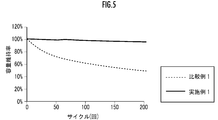
- FIG. 5 shows the change in capacity retention rate with respect to the number of cycles
- FIG. 6 shows the internal resistance before the start of operation (0 cycle) and after 200 cycles when measuring the capacity maintenance rate for the resistance increase rate.
- the lithium ion secondary battery 1 of Example 1 is superior in both energy density and output density to the lithium ion secondary battery 11 of Comparative Example 1, and is also excellent in charge / discharge cycle characteristics. It is clear that
- the basis weight of the positive electrode active material layer 23 or the negative electrode active material layer 33 per electrode is increased by using the three-dimensional skeleton current collector. be able to. Therefore, according to the lithium ion secondary battery 1 of Example 1, compared with the lithium ion secondary battery 11 of Comparative Example 1, the number of electrodes can be reduced, and the mass as a lithium ion secondary battery is reduced. Energy density can be improved.
- SYMBOLS 1 Lithium ion secondary battery, 2 ... 1st positive electrode, 3 ... 1st negative electrode, 6 ... 2nd positive electrode, 7 ... 2nd negative electrode, 21 ... 1st positive electrode active material, 22 ... 2nd Positive electrode active material, 23 ... positive electrode active material, 31 ... first negative electrode active material, 32 ... second negative electrode active material, 33 ... negative electrode active material.
Abstract
Description
まず、高容量型活物質としてのLi(Ni5/10Co2/10Mn3/10)O2、Li(Ni6/10Co2/10Mn2/10)O2、Li(Ni8/10Co1/10Mn1/10)O2、Li(Ni0.8Co0.15Al0.05)O2からなる群から選択される少なくとも1種と、結着剤としてのポリフッ化ビニリデン(PVDF)と、導電助剤としてのカーボンブラックとを、高容量型活物質:結着剤:導電助剤=80~99:0.5~19.5:0.5~19.5の質量比で全量が100となるように混合し、N-メチルピロリドン等の有機溶剤で希釈することにより、第1の正極活物質用スラリーを調製する。 <Production of positive electrode>
First, Li (Ni 5/10 Co 2/10 Mn 3/10 ) O 2 , Li (Ni 6/10 Co 2/10 Mn 2/10 ) O 2 , Li (Ni 8 / 10 Co 1/10 Mn 1/10 ) O 2 , Li (Ni 0.8 Co 0.15 Al 0.05 ) O 2 , and polyvinylidene fluoride as a binder (PVDF) and carbon black as a conductive auxiliary agent, high-capacity active material: binder: conductive auxiliary agent = 80 to 99: 0.5 to 19.5: mass of 0.5 to 19.5 A first slurry for positive electrode active material is prepared by mixing so that the total amount becomes 100 and diluting with an organic solvent such as N-methylpyrrolidone.
まず、高容量型活物質としての人工黒鉛、天然黒鉛、Si、SiOかからなる群から選択される少なくとも1種と、結着剤としてのカルボキシメチルセルロース、スチレンブタジエンゴム、ポリアクリル酸ナトリウム、ポリフッ化ビニリデンからなる群から選択される少なくとも1種と、導電助剤としてのカーボンブラックとを、高容量型活物質:結着剤:導電助剤=80~99.5:0.5~20:0~10の質量比で全量が100となるように混合し、N-メチルピロリドン等の有機溶剤又は純水で希釈することにより、第1の負極活物質用スラリーを調製する。 <Manufacture of negative electrode>
First, at least one selected from the group consisting of artificial graphite, natural graphite, Si, and SiO as a high-capacity active material, and carboxymethyl cellulose, styrene butadiene rubber, sodium polyacrylate, polyfluoride as a binder At least one selected from the group consisting of vinylidene and carbon black as a conductive assistant, a high-capacity active material: binder: conductive assistant = 80 to 99.5: 0.5 to 20: 0 A first slurry for the negative electrode active material is prepared by mixing so that the total amount becomes 100 at a mass ratio of ˜10 and diluting with an organic solvent such as N-methylpyrrolidone or pure water.
次に、同数の第1の正極2と第1の負極3とを、第1のセパレータ4又は第2のセパレータ5を介して交互に配設し、一方の端部には第2の正極6を配設し、他方の端部には第2の負極7を配設する。このとき、第1の正極2の第1の正極活物質21は第1のセパレータ4を介して隣接する第1の負極3の第1の負極活物質31と対向し、第2の正極活物質22は第2のセパレータ5を介して隣接する第1の負極3の第2の負極活物質32と対向するようにする。 <Manufacture of lithium ion secondary batteries>
Next, the same number of first
本実施例では、まず、柱状の骨格が三次元に連なった三次元網目状構造を有する金属多孔体からなる集電体(以下、「三次元骨格集電体」と略記する)として、アルミニウムからなり、気孔率95%、空孔(セル)数46~50個/インチ、空孔径0.5mm、比表面積5000m2/m3、厚さ1.0mm、縦150mm、横200mmのもの(住友電気工業株式会社製セルメット(登録商標))を用いて、次のようにして第1の正極2を作成した。 [Example 1]
In this example, first, a current collector made of a metal porous body having a three-dimensional network structure in which columnar skeletons are three-dimensionally connected (hereinafter abbreviated as “three-dimensional skeleton current collector”) is made of aluminum. With a porosity of 95%, a number of holes (cells) of 46 to 50 / inch, a hole diameter of 0.5 mm, a specific surface area of 5000 m 2 / m 3 , a thickness of 1.0 mm, a length of 150 mm, and a width of 200 mm (Sumitomo Electric) Using the Celmet (registered trademark) manufactured by Kogyo Co., Ltd., a first
次に、本実施例で作製したリチウムイオン二次電池1について、第1の正極活物質21及び第2の正極活物質22の活物質量から、25℃の温度における正極の仮容量を算出した。次に、前記仮容量に基づき、5時間で放電できる(0.2C)電流値を決定した。 <Calculation of energy density>
Next, for the lithium ion
結果を図3に示す。尚、図3では、後述の比較例1のリチウムイオン二次電池11におけるエネルギー密度(Wh/g)を1とし、これに対する比の値として示している。 Energy density (Wh / g) = Rated capacity (mAh / g) x Average voltage (V) (1)
The results are shown in FIG. In FIG. 3, the energy density (Wh / g) in the lithium ion secondary battery 11 of Comparative Example 1 described later is set to 1, and the ratio value is shown.
次に、25℃の温度で、前記定格電流に対し充電率(SOC)が50%となる容量にするために0.2Cで2.5時間充電し、このときの開路電圧(OCV)をE0とした。 <Calculation of output density>
Next, at a temperature of 25 ° C., the battery is charged at 0.2 C for 2.5 hours in order to obtain a capacity with a charge rate (SOC) of 50% with respect to the rated current, and the open circuit voltage (OCV) at this time is E 0 .
結果を図4に示す。尚、図4では、後述の比較例1のリチウムイオン二次電池における出力密度を1とし、これに対する比の値として示している。 W = (| E cutoff− E 0 | / R) × E cutoff (2)
The results are shown in FIG. In FIG. 4, the power density in a lithium ion secondary battery of Comparative Example 1 described later is set to 1, and the ratio value is shown.
次に、前記定格容量に対し、0.5Cで4.2Vまで定電流充電し、0.5Cで2.4Vまで定電流放電を行う操作を1サイクルとし、45℃において該操作を200サイクル繰り返した。サイクル数に対する容量維持率の変化を図5に示す。 <Durability Evaluation: Capacity Maintenance Rate>
Next, with respect to the above-mentioned rated capacity, an operation of constant current charging to 4.2 V at 0.5 C and constant current discharging to 0.5 V at 0.5 C is defined as one cycle, and the operation is repeated 200 cycles at 45 ° C. It was. FIG. 5 shows the change in capacity retention rate with respect to the number of cycles.
本実施例で作製したリチウムイオン二次電池11について、前記容量維持率の測定時に、前記操作の開始前(0サイクル)と、200サイクル後との内部抵抗を測定した。結果を図6に示す。 <Durability Evaluation: Resistance Increase Rate>
For the lithium ion secondary battery 11 produced in this example, the internal resistance before the start of the operation (0 cycle) and after 200 cycles was measured when the capacity retention rate was measured. The results are shown in FIG.
図2に示すように、本比較例のリチウムイオン二次電池11は、同数の第1の正極12と、第1の負極13とが、交互にセパレータ14を介して隣接する構造を備え、一方の端部には第2の正極16が配設され、他方の端部には第2の負極17が配設されている。 [Comparative Example 1]
As shown in FIG. 2, the lithium ion secondary battery 11 of this comparative example has a structure in which the same number of first
Claims (3)
- 三次元網目状構造を有する金属多孔体からなる正極集電体と、前記正極集電体の一方の面に保持された高容量型活物質を含む第1の正極活物質と、前記正極集電体の他方の面に保持された高出力型活物質を含む第2の正極活物質を備える少なくとも一つの正極と、
三次元網目状構造を有する金属多孔体からなる負極集電体と、前記負極集電体の一方の面に保持された高容量型活物質を含む第1の負極活物質と、前記負極集電体の他方の面に保持された高出力型活物質を含む第2の負極活物質を備える少なくとも一つの負極とが、交互にセパレータを介して隣接する構造を備え、
前記第1の正極活物質は、第1のセパレータを介して隣接する前記第1の負極活物質と対向し、前記第2の正極活物質は、第2のセパレータを介して隣接する前記負極の第2の負極活物質と対向していることを特徴とするリチウムイオン二次電池。 A positive electrode current collector made of a porous metal body having a three-dimensional network structure, a first positive electrode active material containing a high capacity active material held on one surface of the positive electrode current collector, and the positive electrode current collector At least one positive electrode comprising a second positive electrode active material comprising a high power active material held on the other side of the body;
A negative electrode current collector made of a porous metal body having a three-dimensional network structure, a first negative electrode active material containing a high-capacity active material held on one surface of the negative electrode current collector, and the negative electrode current collector A structure in which at least one negative electrode including a second negative electrode active material containing a high-power active material held on the other surface of the body is alternately adjacent via a separator;
The first positive electrode active material is opposed to the first negative electrode active material adjacent through a first separator, and the second positive electrode active material is adjacent to the negative electrode through a second separator. A lithium ion secondary battery, characterized by facing the second negative electrode active material. - 請求項1記載のリチウムイオン二次電池において、前記第1の正極活物質は、Li(Ni5/10Co2/10Mn3/10)O2、Li(Ni6/10Co2/10Mn2/10)O2、Li(Ni8/10Co1/10Mn1/10)O2、Li(Ni0.8Co0.15Al0.05)O2からなる群から選択される少なくとも1種を含み、
前記第2の正極活物質は、Li(Ni1/6Co4/6Mn1/6)O2、Li(Ni1/3Co1/3Mn1/3)O2からなる群から選択される少なくとも1種を含むことを特徴とするリチウムイオン二次電池。 2. The lithium ion secondary battery according to claim 1, wherein the first positive electrode active material is Li (Ni 5/10 Co 2/10 Mn 3/10 ) O 2 , Li (Ni 6/10 Co 2/10 Mn). 2/10 ) O 2 , Li (Ni 8/10 Co 1/10 Mn 1/10 ) O 2 , Li (Ni 0.8 Co 0.15 Al 0.05 ) O 2 Including one species,
The second positive electrode active material is selected from the group consisting of Li (Ni 1/6 Co 4/6 Mn 1/6 ) O 2 and Li (Ni 1/3 Co 1/3 Mn 1/3 ) O 2. A lithium ion secondary battery comprising at least one selected from the group consisting of: - 請求項1記載のリチウムイオン二次電池において、前記第1の負極活物質は、人工黒鉛、天然黒鉛、Si、SiOからなる群から選択される少なくとも1種を含み、
前記第2の負極活物質は、ハードカーボンを含むことを特徴とするリチウムイオン二次電池。 2. The lithium ion secondary battery according to claim 1, wherein the first negative electrode active material includes at least one selected from the group consisting of artificial graphite, natural graphite, Si, and SiO,
The lithium ion secondary battery, wherein the second negative electrode active material contains hard carbon.
Priority Applications (4)
| Application Number | Priority Date | Filing Date | Title |
|---|---|---|---|
| JP2020519596A JPWO2019221004A1 (en) | 2018-05-17 | 2019-05-09 | Lithium ion secondary battery |
| EP19802623.9A EP3796453B1 (en) | 2018-05-17 | 2019-05-09 | Lithium ion secondary battery |
| US17/054,697 US11949111B2 (en) | 2018-05-17 | 2019-05-09 | Lithium ion secondary battery |
| CN201980028480.3A CN112204799A (en) | 2018-05-17 | 2019-05-09 | Lithium ion secondary battery |
Applications Claiming Priority (2)
| Application Number | Priority Date | Filing Date | Title |
|---|---|---|---|
| JP2018095344 | 2018-05-17 | ||
| JP2018-095344 | 2018-05-17 |
Publications (1)
| Publication Number | Publication Date |
|---|---|
| WO2019221004A1 true WO2019221004A1 (en) | 2019-11-21 |
Family
ID=68540247
Family Applications (1)
| Application Number | Title | Priority Date | Filing Date |
|---|---|---|---|
| PCT/JP2019/018563 WO2019221004A1 (en) | 2018-05-17 | 2019-05-09 | Lithium ion secondary battery |
Country Status (5)
| Country | Link |
|---|---|
| US (1) | US11949111B2 (en) |
| EP (1) | EP3796453B1 (en) |
| JP (1) | JPWO2019221004A1 (en) |
| CN (1) | CN112204799A (en) |
| WO (1) | WO2019221004A1 (en) |
Citations (7)
| Publication number | Priority date | Publication date | Assignee | Title |
|---|---|---|---|---|
| JP2002151055A (en) | 2000-08-28 | 2002-05-24 | Nissan Motor Co Ltd | Lithium ion secondary battery |
| JP2009032444A (en) * | 2007-07-25 | 2009-02-12 | Toyota Motor Corp | Lithium secondary battery |
| JP2013020735A (en) * | 2011-07-07 | 2013-01-31 | Gs Yuasa Corp | Nonaqueous electrolyte secondary battery and method for manufacturing the same |
| JP2014225430A (en) * | 2013-05-14 | 2014-12-04 | 三星エスディアイ株式会社Samsung SDI Co.,Ltd. | Lithium secondary battery |
| JP2015037024A (en) * | 2013-08-12 | 2015-02-23 | 住友電気工業株式会社 | Lithium ion secondary battery, charge-discharge system, and method for charge and discharge |
| JP2017501535A (en) * | 2013-12-03 | 2017-01-12 | エルジー・ケム・リミテッド | Hybrid secondary battery including electrodes having different output and capacity characteristics |
| JP2017101887A (en) | 2015-12-03 | 2017-06-08 | クボタ空調株式会社 | Humidity controller |
Family Cites Families (15)
| Publication number | Priority date | Publication date | Assignee | Title |
|---|---|---|---|---|
| JP4696557B2 (en) * | 2005-01-06 | 2011-06-08 | 日本電気株式会社 | Active material for lithium secondary battery, production method thereof, raw material used therefor, and lithium secondary battery |
| US20110311854A1 (en) * | 2007-01-03 | 2011-12-22 | Greatbatch Ltd. | Electrochemical Cell Electrode With Sandwich Cathode And Method For Making Same |
| WO2010013405A1 (en) * | 2008-07-29 | 2010-02-04 | パナソニック株式会社 | Current collector for nonaqueous electrolyte secondary battery, electrode for nonaqueous electrolyte secondary battery, method for manufacturing the current collector and the electrode, and nonaqueous electrolyte secondary battery |
| JP2011204563A (en) * | 2010-03-26 | 2011-10-13 | Nissan Motor Co Ltd | Method of manufacturing nonaqueous secondary battery |
| JP2012256584A (en) * | 2011-02-18 | 2012-12-27 | Sumitomo Electric Ind Ltd | Electrochemical element |
| KR101375158B1 (en) * | 2011-11-17 | 2014-03-17 | 주식회사 샤인 | Electrode assembly, manufacturing the samem, and method of charging and discharging a battery |
| JPWO2013140942A1 (en) * | 2012-03-22 | 2015-08-03 | 住友電気工業株式会社 | All-solid lithium secondary battery |
| KR20140148384A (en) * | 2012-03-22 | 2014-12-31 | 스미토모덴키고교가부시키가이샤 | Lithium secondary battery |
| KR101353262B1 (en) * | 2013-04-19 | 2014-01-23 | 주식회사 셀모티브 | Metal foam for electrode of lithium secondary battery, preparing method thereof and lithium secondary battery including the metalfoam |
| KR101558774B1 (en) * | 2013-05-23 | 2015-10-08 | 주식회사 엘지화학 | Lithium secondary battery comprising multilayered active materials |
| JP6056703B2 (en) | 2013-08-12 | 2017-01-11 | トヨタ自動車株式会社 | Lithium ion secondary battery |
| KR20160005555A (en) * | 2014-07-07 | 2016-01-15 | 삼성에스디아이 주식회사 | Lithium battery |
| JP2016058257A (en) * | 2014-09-10 | 2016-04-21 | 三菱マテリアル株式会社 | Positive electrode for lithium ion secondary battery, and lithium ion secondary battery |
| CN108352504B (en) * | 2016-06-14 | 2021-03-30 | 株式会社Lg化学 | Electrode for secondary battery and lithium secondary battery comprising the same |
| JP6895105B2 (en) * | 2016-08-01 | 2021-06-30 | 住友金属鉱山株式会社 | A method for producing nickel-manganese composite hydroxide particles and a method for producing a positive electrode active material for a non-aqueous electrolyte secondary battery. |
-
2019
- 2019-05-09 EP EP19802623.9A patent/EP3796453B1/en active Active
- 2019-05-09 CN CN201980028480.3A patent/CN112204799A/en active Pending
- 2019-05-09 JP JP2020519596A patent/JPWO2019221004A1/en active Pending
- 2019-05-09 US US17/054,697 patent/US11949111B2/en active Active
- 2019-05-09 WO PCT/JP2019/018563 patent/WO2019221004A1/en active Application Filing
Patent Citations (7)
| Publication number | Priority date | Publication date | Assignee | Title |
|---|---|---|---|---|
| JP2002151055A (en) | 2000-08-28 | 2002-05-24 | Nissan Motor Co Ltd | Lithium ion secondary battery |
| JP2009032444A (en) * | 2007-07-25 | 2009-02-12 | Toyota Motor Corp | Lithium secondary battery |
| JP2013020735A (en) * | 2011-07-07 | 2013-01-31 | Gs Yuasa Corp | Nonaqueous electrolyte secondary battery and method for manufacturing the same |
| JP2014225430A (en) * | 2013-05-14 | 2014-12-04 | 三星エスディアイ株式会社Samsung SDI Co.,Ltd. | Lithium secondary battery |
| JP2015037024A (en) * | 2013-08-12 | 2015-02-23 | 住友電気工業株式会社 | Lithium ion secondary battery, charge-discharge system, and method for charge and discharge |
| JP2017501535A (en) * | 2013-12-03 | 2017-01-12 | エルジー・ケム・リミテッド | Hybrid secondary battery including electrodes having different output and capacity characteristics |
| JP2017101887A (en) | 2015-12-03 | 2017-06-08 | クボタ空調株式会社 | Humidity controller |
Non-Patent Citations (1)
| Title |
|---|
| See also references of EP3796453A4 |
Also Published As
| Publication number | Publication date |
|---|---|
| US11949111B2 (en) | 2024-04-02 |
| JPWO2019221004A1 (en) | 2021-06-10 |
| US20210075020A1 (en) | 2021-03-11 |
| EP3796453A4 (en) | 2021-07-07 |
| EP3796453A1 (en) | 2021-03-24 |
| EP3796453B1 (en) | 2022-11-09 |
| CN112204799A (en) | 2021-01-08 |
Similar Documents
| Publication | Publication Date | Title |
|---|---|---|
| EP3573149B1 (en) | Battery and testing method of active specific surface area of electrode plate | |
| RU2361326C2 (en) | Accumulator battery with improved mobility of lithium ions and improved capacitance of cells | |
| JP7254875B2 (en) | Positive electrode active material for lithium secondary battery and lithium secondary battery containing the same | |
| WO2003088404A1 (en) | Nonaqueous electrolyte secondary battery | |
| WO2019230322A1 (en) | Negative electrode for lithium ion secondary battery | |
| JP2016091984A (en) | Power storage element | |
| JP2019160782A (en) | Negative electrode and lithium ion secondary battery | |
| JP2013254647A (en) | Lithium ion-lithium air composite secondary battery, charging/discharging method using the same, and cathode material for lithium ion-lithium air composite secondary battery | |
| KR20110019101A (en) | Lithium powder and silicon oxide double layer anode, method of manufacturing the anode and lithium secondary battery using the anode | |
| JP4839117B2 (en) | Cylindrical lithium secondary battery | |
| CN114050325A (en) | Battery cell and electrochemical device | |
| US20200403224A1 (en) | Lithium molybdate anode material | |
| JP2018198132A (en) | Cathode for lithium ion secondary battery and lithium ion secondary battery employing the same | |
| JPH06260168A (en) | Lithium secondary battery | |
| JP6573150B2 (en) | Electricity storage element | |
| KR20020094530A (en) | Current collector coated with metal, electrodes comprising it, and lithium batteries comprising the electrodes | |
| WO2019221004A1 (en) | Lithium ion secondary battery | |
| JP6613952B2 (en) | Positive electrode active material, and positive electrode and lithium ion secondary battery using the same | |
| KR20140048010A (en) | Positive electrode for lithium ion secondary battery and lithium ion secondary battery including the same | |
| WO2019220985A1 (en) | Lithium ion secondary battery electrode | |
| KR20000075095A (en) | A positive electrode for a lithium secondary battery, a method of preparing the same, and a lithium secondary battery using the same | |
| JP2004234994A (en) | Lithium secondary battery, battery pack of same, and electrode of same | |
| JP3048953B2 (en) | Non-aqueous electrolyte secondary battery | |
| CN113036225B (en) | Method for manufacturing lithium ion battery | |
| WO2021100225A1 (en) | Non-aqueous electrolyte secondary battery |
Legal Events
| Date | Code | Title | Description |
|---|---|---|---|
| 121 | Ep: the epo has been informed by wipo that ep was designated in this application |
Ref document number: 19802623 Country of ref document: EP Kind code of ref document: A1 |
|
| ENP | Entry into the national phase |
Ref document number: 2020519596 Country of ref document: JP Kind code of ref document: A |
|
| NENP | Non-entry into the national phase |
Ref country code: DE |
|
| WWE | Wipo information: entry into national phase |
Ref document number: 2019802623 Country of ref document: EP |
|
| ENP | Entry into the national phase |
Ref document number: 2019802623 Country of ref document: EP Effective date: 20201217 |