WO2019220870A1 - プリズムプレート及び光照射装置 - Google Patents
プリズムプレート及び光照射装置 Download PDFInfo
- Publication number
- WO2019220870A1 WO2019220870A1 PCT/JP2019/016942 JP2019016942W WO2019220870A1 WO 2019220870 A1 WO2019220870 A1 WO 2019220870A1 JP 2019016942 W JP2019016942 W JP 2019016942W WO 2019220870 A1 WO2019220870 A1 WO 2019220870A1
- Authority
- WO
- WIPO (PCT)
- Prior art keywords
- prism
- incident
- exit
- side prism
- light
- Prior art date
- Legal status (The legal status is an assumption and is not a legal conclusion. Google has not performed a legal analysis and makes no representation as to the accuracy of the status listed.)
- Ceased
Links
Images





Classifications
-
- F—MECHANICAL ENGINEERING; LIGHTING; HEATING; WEAPONS; BLASTING
- F21—LIGHTING
- F21S—NON-PORTABLE LIGHTING DEVICES; SYSTEMS THEREOF; VEHICLE LIGHTING DEVICES SPECIALLY ADAPTED FOR VEHICLE EXTERIORS
- F21S2/00—Systems of lighting devices, not provided for in main groups F21S4/00 - F21S10/00 or F21S19/00, e.g. of modular construction
-
- F—MECHANICAL ENGINEERING; LIGHTING; HEATING; WEAPONS; BLASTING
- F21—LIGHTING
- F21V—FUNCTIONAL FEATURES OR DETAILS OF LIGHTING DEVICES OR SYSTEMS THEREOF; STRUCTURAL COMBINATIONS OF LIGHTING DEVICES WITH OTHER ARTICLES, NOT OTHERWISE PROVIDED FOR
- F21V5/00—Refractors for light sources
-
- F—MECHANICAL ENGINEERING; LIGHTING; HEATING; WEAPONS; BLASTING
- F21—LIGHTING
- F21V—FUNCTIONAL FEATURES OR DETAILS OF LIGHTING DEVICES OR SYSTEMS THEREOF; STRUCTURAL COMBINATIONS OF LIGHTING DEVICES WITH OTHER ARTICLES, NOT OTHERWISE PROVIDED FOR
- F21V5/00—Refractors for light sources
- F21V5/02—Refractors for light sources of prismatic shape
-
- G—PHYSICS
- G02—OPTICS
- G02B—OPTICAL ELEMENTS, SYSTEMS OR APPARATUS
- G02B5/00—Optical elements other than lenses
- G02B5/02—Diffusing elements; Afocal elements
-
- G—PHYSICS
- G02—OPTICS
- G02B—OPTICAL ELEMENTS, SYSTEMS OR APPARATUS
- G02B5/00—Optical elements other than lenses
- G02B5/04—Prisms
Definitions
- the present invention relates to a prism plate and a light irradiation device.
- liquid crystal display devices having a light source unit (light irradiation device) for illuminating a liquid crystal panel are widely known.
- a light source unit for illuminating a liquid crystal panel
- a point light source such as a light emitting diode as a light source Are arranged at intervals.
- the amount of incident light is different between the portion facing the light source and the portion between the light sources in the liquid crystal panel, and a difference in light intensity (brightness unevenness) occurs on the liquid crystal panel, resulting in a striped pattern Etc. occurred.
- production of such a brightness nonuniformity is made conventionally (for example, refer patent document 1).
- the conventional light source unit suppresses the luminance unevenness on the liquid crystal panel.
- the conventional light source unit is required to further suppress the luminance unevenness.
- the present invention has been made in view of the above-described problems, and an object of the present invention is to provide a prism plate and light irradiation capable of uniformly distributing light while suppressing unevenness in luminance of light emitted from a plurality of light sources. To provide an apparatus.
- a prism plate includes a translucent base material having a pair of surfaces and a translucency extending side by side forming a prism on one surface of the pair of surfaces.
- An incident-side prism surface having a plurality of incident-side prism portions, and an exit-side prism surface having a plurality of light-transmitting exit-side prism portions extending side by side, forming a prism on the other surface of the pair of surfaces.
- the incident-side prism surface and the emission-side prism surface are different from each other in shape.
- the prism plate which concerns on 1 aspect of this invention WHEREIN The said incident side prism part is the incident side prism part which is convex from one surface of said pair of surface, and the incident side which is concave from one surface of said pair of surface
- One of the prism portions, and the exit-side prism portion is an exit-side prism portion that is convex from the other surface of the pair of surfaces, and an exit-side prism portion that is concave from the other surface of the pair of surfaces Either one of them.
- the plurality of incident side prism portions have the same shape on the incident side prism surface, and the plurality of emission side prism portions on the output side prism surface. Have the same shape.
- the plurality of incident side prism portions have the same shape on the incident side prism surface, and the plurality of emission side prism portions on the output side prism surface. Among them, the remaining ones of the plurality of exit-side prism portions have different shapes.
- the outline in the cross section facing the extending direction of the incident-side prism portion is a curved surface, a part of a polygon, or a mountain shape.
- the contour in the cross section facing the extending direction of the exit side prism portion is a curved surface, a part of a polygon, or a mountain shape.
- a part of the exit side prism portion is sharper than the rest of the exit side prism portion.
- a contour in a cross section facing in the extending direction of a part of the emission-side prism part is a curved surface or a part of a polygon.
- the contour in the remaining cross section facing the extending direction is chevron.
- a part of the exit side prism part and the rest of the exit side prism part are repeatedly arranged in a predetermined combination.
- the incident-side prism portions are arranged adjacent to each other or at a predetermined interval.
- the emission-side prism portions are arranged adjacent to each other or at a predetermined interval.
- a light irradiation apparatus includes a plurality of light sources arranged side by side and a light emitting surface of the plurality of light sources so that the incident-side prism surface faces or is close to the light source. And any one of the prism plates described above.
- the plurality of emission-side prism portions extend in a direction orthogonal to the arrangement direction of the plurality of light sources, and are parallel to the extending direction of the plurality of incident-side prism portions. It extends.
- the prism plate and the light irradiation device it is possible to uniformly distribute light while suppressing unevenness in luminance of light emitted from a plurality of light sources.
- FIG. 1 is a plan view schematically showing the configuration of the light source unit 1 according to the first embodiment of the present invention
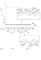
- FIG. 2 is a side view schematically showing the configuration of the light source unit 1.
- FIG. 3 is a partially enlarged plan view schematically showing the configuration of the light source unit 1
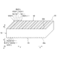
- FIG. 4 is a partially enlarged perspective view schematically showing the configuration of the prism plate 20 according to the embodiment of the present invention.
- the emission direction of the plurality of light sources 10 in FIG. 1 is the short direction of the light source unit 1, for convenience, the arrow ab direction, the arrow a direction is the upper side, and the arrow b direction is the lower side.
- the arrangement direction of the plurality of light sources 10 in FIG. Further, the direction orthogonal to the arrangement direction of the plurality of light sources 10 in FIG. 1 is defined as the depth direction of the light source unit 1 (perpendicular to the paper surface), for convenience, the arrow ef direction, the arrow e direction is the front side, The direction is the back side.
- the positional relationship and direction of each member when explaining the positional relationship and direction of each member using up, down, left and right, etc., it indicates the positional relationship and direction in the drawing to the last, and indicates the positional relationship and direction when incorporated in an actual device is not.
- a light source unit (light irradiation device) 1 includes a plurality of light sources that are arranged side by side on a flexible printed circuit board (hereinafter also referred to as an FPC board) (not shown).
- a light source 10 and a prism plate 20 disposed in contact with or close to the emission surfaces 10a of the plurality of light sources 10 are provided.
- the prism plate 20 includes a translucent base material 30 having a pair of surfaces (incident surface 30a and output surface 30b) and an incident surface 30a as one surface of the pair of surfaces (incident surface 30a and output surface 30b).
- the incident-side prism surface 40 has a plurality of light-transmitting incident-side prism portions 41 extending side by side
- the output-side prism surface 50 is a plurality of light-transmitting output-side prism portions 51 extending side by side. have.
- the shapes of the incident side prism surface 40 and the output side prism surface 50 are different from each other.
- the incident side prism surface 40 and the output side prism surface 50 may be similar to each other.
- the configuration of the light source unit 1 will be described in detail.
- a plurality of light sources 10 are provided on the surface of the FPC board (not shown).
- the prism plate 20 is disposed in contact with or close to the exit surfaces 10a of the plurality of light sources 10 so that the incident-side prism surface 40 faces each other.
- the prism plates 20 are disposed on the exit surfaces 10a of the plurality of light sources 10. It is provided facing.
- the glass substrate 2 is provided on the upper side (arrow a direction) in the emission direction of the light sources 10 (short direction of the light source unit 1 (arrow ab direction)).
- the plurality of light sources 10 are linear or substantially linear with a predetermined interval S1 in the direction in which the plurality of light sources 10 are arranged (longitudinal direction of light source unit 1 (arrow cd direction)). Are arranged side by side.
- positioning form of the several light source 10 is not restricted to this, You may arrange
- the plurality of light sources 10 are electrically connected to the conductive layer (wiring) of the FPC board, and are connected to an external control module or the like (not shown) via the conductive layer (wiring) of the FPC board.
- the plurality of light sources 10 emit light from the emission surface 10a toward the upper side (arrow a direction) in the short direction (arrow ab direction) of the light source unit 1 based on an instruction signal transmitted from the control module or the like. It has become.
- the plurality of light sources 10 are, for example, LEDs (light emitting diodes).
- the plurality of light sources 10 is not limited to this, and may be a known light emitting element such as an LD (laser diode), or may be a light emitting element having red, green, and blue LEDs.
- the prism plate 20 is formed in a rectangular plate shape or a substantially rectangular plate shape as shown in FIGS.
- the prism plate 20 is configured to transmit light emitted from the plurality of light sources 10 and is formed of a translucent material, particularly a colorless and transparent synthetic resin.
- the prism plate 20 is made of, for example, polyethylene terephthalate, polyethylene naphthalate, acrylic resin, polycarbonate resin, polystyrene, polyolefin, cellulose acetate, weather resistant vinyl chloride, active energy ray curable resin, or the like.
- the prism plate 20 includes a base plate 30 formed in a rectangular plate shape or a substantially rectangular plate shape, an incident side prism surface 40 formed on the incident surface 30 a side of the base material 30, and an output surface 30 b side of the base material 30. And an exit-side prism surface 50 formed.
- the incident surface 30 a of the prism plate 20 is disposed to face the emission surfaces 10 a of the plurality of light sources 10.
- the incident surface 30 a of the prism plate 20 is in contact with or close to the emission surfaces 10 a of the plurality of light sources 10.
- the prism plate 20 receives light emitted from the emission surfaces 10a of the plurality of light sources 10 at the incident surface 30a and emits the light from the emission surface 30b.
- the base material 30, the incident side prism surface 40, and the output side prism surface 50 in the prism plate 20 are integrally formed.
- the material of the prism plate 20 is not limited to this, and polyethylene terephthalate, polyethylene naphthalate, or polycarbonate resin may be used as the base material 30, and the incident surface 30a and the output surface 30b are made of ultraviolet curable resin or the like.
- the incident side prism surface 40 and the output side prism surface 50 may be formed. Further, the incident-side prism surface 40 is formed in a single sheet shape, and the output-side prism surface 50 is formed in a single sheet shape, and these sheets are formed on the incident surface 30a,
- the prism plate 20 may be formed by affixing one or more to the exit surface 30b.
- the incident-side prism surface 40 has a plurality of light-transmitting incident-side prism portions 41.
- the incident-side prism portions 41 extend side by side.
- the incident side prism portion 41 is, for example, one of an incident side prism portion 41 that is convex from the incident surface 30a and an incident side prism portion 41 that is concave from the incident surface 30a.
- the incident-side prism portion 41 is convex from the incident surface 30a.
- the exit-side prism surface 50 has a plurality of light-transmitting exit-side prism portions 51, and the exit-side prism portions 51 extend side by side on the exit-side prism surface 50.
- the exit side prism portion 51 is, for example, one of the exit side prism portion 51 that is convex from the exit surface 30b and the exit side prism portion 51 that is concave from the exit surface 30b.
- the exit-side prism portion 51 is convex from the exit surface 30 b.
- the plurality of incident side prism portions 41 may have the same shape, and a part of the plurality of incident side prism portions 41 and the plurality of incident side prism portions 41 are arranged. You may have a mutually different shape from the remainder of them.
- the plurality of incident-side prism portions 41 have the same or substantially the same shape.
- the incident side prism portion 41 of the prism plate 20 according to the present embodiment is referred to as an incident side convex prism portion 42.
- the plurality of exit side prism parts 51 may have the same shape, and a part of the plurality of exit side prism parts 51 and the plurality of exit side prism parts 51 You may have a mutually different shape from the remainder of them.
- a part of the plurality of exit-side prism parts 51 has a different shape from the rest of the plurality of exit-side prism parts 51. have.
- the exit-side prism surface 50 includes an exit-side convex prism portion 52 that is a part of the plurality of exit-side prism portions 51 and an exit-side pointed convex that is the remainder of the plurality of exit-side prism portions 51. And a prism portion 53.
- the plurality of incident-side convex prism portions 42 are respectively lower (arrow b direction) in the emission direction of the light sources 10 (short direction of the light source unit 1 (arrow ab direction)) from the incident surface 30 a.
- the light sources 10 are arranged in parallel or substantially parallel to the direction in which the light sources 10 are arranged (the longitudinal direction of the light source unit 1 (arrow cd direction)).
- the plurality of incident-side convex prism portions 42 extend in a direction orthogonal to or substantially orthogonal to the arrangement direction of the plurality of light sources 10 (the depth direction of the light source unit 1 (arrow ef direction)).
- Each of the plurality of incident-side convex prism portions 42 may extend obliquely with respect to the arrangement direction of the plurality of light sources 10 (longitudinal direction of the light source unit 1 (arrow cd direction)).
- the incident-side convex prism portion 42 has, for example, a curved contour in a cross section facing the extending direction (depth direction (arrow ef direction)) of the incident-side convex prism portion 42.
- the incident-side convex prism portion 42 is an arc having a constant curvature in a cross section facing in the extending direction (depth direction (arrow ef direction)).
- the width in the longitudinal direction (arrow cd direction) of the incident side convex prism portion 42 is longer than the height in the short direction (arrow ab direction).
- the incident-side convex prism portion 42 is, for example, a part of a cylindrical shape or a substantially cylindrical shape, and is formed by a lenticular lens, a cylindrical lens, or the like.
- the outline in the cross section facing the extending direction (depth direction (arrow ef direction)) of the incident-side convex prism portion 42 is not limited thereto, and may be a curved surface having a plurality of curvatures.
- the incident-side convex prism portion 42 has, for example, a part of an elliptical column shape or a substantially elliptical column shape, or a part of a bowl shape or a substantially bowl shape, and is formed by a lenticular lens or a cylindrical lens.
- the contour of the cross section facing the extending direction (depth direction (arrow ef direction)) of the incident-side convex prism portion 42 is not limited to this, and may be a part of a polygon such as a triangle, pentagon, or hexagon. Good.
- the cross section facing the extending direction (depth direction (arrow ef direction)) in the incident side convex prism portion 42 is, for example, a part of a polygon extending in an arc shape.
- the outline of the cross section in the extending direction of the incident side convex prism portion 42 is not limited to the shape described above, and may be another shape in which the incident side convex prism portion 42 protrudes from the incident surface 30a.
- the incident side convex prism portions 42 extend side by side with a predetermined interval S2.
- the width in the longitudinal direction (arrow cd direction) of the incident side convex prism portion 42 is longer than the width in the longitudinal direction (arrow cd direction) of the predetermined interval S2.
- interval S2 does not need to be provided between the incident side convex prism part 42 and the incident side convex prism part 42 adjacent to this. Further, the interval S2 may not have a constant width in the depth direction (arrow ef direction).
- the plurality of exit-side convex prism portions 52 are convex from the exit surface 30 b toward the upper side (arrow a direction) in the exit direction (short direction (arrow ab direction)) of the plurality of light sources 10. And extending parallel to or substantially parallel to the direction of arrangement of the light sources 10 (longitudinal direction (arrow cd direction)).
- Each of the plurality of exit-side convex prisms 52 extends in a direction (depth direction (arrow ef direction)) orthogonal to or substantially orthogonal to the direction in which the plurality of light sources 10 are arranged.
- the prism portion 42 extends in parallel or substantially in parallel with the extending direction (depth direction (arrow ef direction)). Note that the plurality of emission-side convex prism portions 52 may extend obliquely with respect to the arrangement direction (longitudinal direction (arrow cd direction)) of the plurality of light sources 10.
- the exit-side convex prism portion 52 has, for example, a curved contour in a cross section facing the extending direction (depth direction (arrow ef direction)) of the output-side convex prism portion 52.
- the exit-side convex prism portion 52 is an arc having a constant curvature in a cross section facing the extending direction (depth direction (arrow ef direction)).
- the width in the longitudinal direction (arrow cd direction) of the exit-side convex prism portion 52 is longer than the height in the short direction (arrow ab direction).
- the emission-side convex prism portion 52 is, for example, a part of a cylindrical shape or a substantially cylindrical shape, and is formed by a lenticular lens, a cylindrical lens, or the like.
- the outline in the cross section facing the extending direction (depth direction (arrow ef direction)) of the exit-side convex prism portion 52 is not limited thereto, and may be a curved surface having a plurality of curvatures.
- the exit-side convex prism portion 52 has, for example, a part of an elliptical column shape or a substantially elliptical column shape, or a part of a bowl shape or a substantially bowl shape, and is formed by a lenticular lens or a cylindrical lens.
- the contour of the cross section facing the extending direction (depth direction (arrow ef direction)) of the exit-side convex prism portion 52 is not limited to this, and may be a part of a polygon such as a triangle, pentagon, or hexagon. Good.
- the cross section facing the extending direction (depth direction (arrow ef direction)) in the exit-side convex prism portion 52 is, for example, a part of a polygon extending in an arc shape.
- the exit-side convex prism portion 52 may be the same as or substantially the same as or different from the incident-side convex prism portion 42.
- the outline of the cross section in the extending direction of the exit-side convex prism portion 52 is not limited to the above-described shape, and may be another shape in which the exit-side convex prism portion 52 protrudes from the exit surface 30b.
- the plurality of emission-side ridge-shaped convex prism portions 53 are directed from the emission surface 30b to the upper side (arrow a direction) in the emission direction (short direction (arrow ab direction)) of the plurality of light sources 10, respectively.
- Each of the plurality of light sources 10 is arranged in the direction of alignment (longitudinal direction (arrow cd direction)) and extends alternately with the exit-side convex prism portion 52. That is, the exit-side ridged prism portion 53 is formed between the exit-side ridge prism portions 52 adjacent to each other.
- the plurality of emission-side sharp ridge prism portions 53 each extend in a direction (depth direction (arrow ef direction)) orthogonal to or substantially orthogonal to the arrangement direction of the plurality of light sources 10, and the plurality of incident sides It extends in parallel or substantially in parallel with the extending direction (depth direction (arrow ef direction)) of the convex prism portion 42 and the output-side convex prism portion 52.
- the plurality of emission-side ridge-shaped convex prism portions 53 may extend obliquely with respect to the arrangement direction (longitudinal direction (arrow cd direction)) of the plurality of light sources 10. There is no gap between the exit-side convex prism portion 52 and the exit-side convex prism portion 53.
- interval between the output side convex prism part 52 and the output side pointed convex prism part 53 may have a predetermined space
- Each of the plurality of emission-side convex ridge prism portions 53 is formed to be sharper than the emission-side ridge prism portion 52.
- the width in the longitudinal direction (arrow cd direction) of the plurality of exit-side convex ridge prism portions 53 is smaller than the width in the longitudinal direction (arrow cd direction) of each of the plurality of exit-side convex ridge prism portions 52.
- the heights in the emission direction (short direction (arrow ab direction)) of the plurality of light sources 10 in the plurality of emission-side convex ridge prism portions 53 are the plurality of light sources in the plurality of emission-side ridge prism portions 52, respectively. It is higher than the height of 10 emission directions (short direction (arrow ab direction)).
- the exit-side ridge-shaped convex prism portion 53 has, for example, a mountain-shaped contour in a cross section facing the extending direction (depth direction (arrow ef direction)) of the emission-side ridge-shaped prism portion 53.
- the emission-side ridge-shaped prism portion 53 faces the extending direction (depth direction (arrow ef direction)) of the emission-side ridge-shaped prism portion 53.
- the top 54 in the outline in the cross section is a curve.
- the exit-side ridge-shaped ridge prism portion 53 has a pair of inclined surfaces facing each other whose contours in the cross section facing the extending direction (depth direction (arrow ef direction)) of the exit-side ridge-shaped ridge prism portion 53 respectively.
- Straight lines 55 and 56 are inclined in a direction away from each other toward the lower side (arrow b direction) in the emission direction (short direction (arrow ab direction)) of the plurality of light sources 10.
- the angle formed by the pair of inclined straight lines 55 and 56 is an acute angle.
- the top part 54 of the emission side pointed convex prism part 53 is not limited to this, and may be a straight line where a pair of inclined straight lines 55 and 56 intersect.
- the angle formed by the pair of inclined straight lines 55 and 56 is not limited to this, and may be a right angle or an obtuse angle.
- the outline of the cross section facing the extending direction (depth direction (arrow ef direction)) of the emission-side ridge-shaped convex prism portion 53 is not limited to this, and is a part of a polygon such as a triangle, pentagon, or hexagon. May be.
- the plurality of emission-side ridge-shaped convex prism portions 53 are formed by, for example, a triangular prism-shaped or substantially triangular prism-shaped prism lens.
- the glass substrate 2 is disposed to face the emission surface 30 b of the prism plate 20.
- the exit surface 30 b of the prism plate 20 is in contact with or close to the end surface 2 a of the glass substrate 2.
- the glass substrate 2 receives light emitted from the emission surface 30 b of the prism plate 20 at the end surface 2 a of the glass substrate 2 and emits the light from the emission surface 2 b of the glass substrate 2. And after that, the light radiate
- the incident-side convex prism portion 42 of the incident-side prism surface 40 which is disposed in contact with or close to the emission surfaces 10a of the plurality of light sources 10,
- a prism plate 20 having an exit-side convex prism portion 52 and an exit-side convex prism portion 53 on the exit-side prism surface 50 is provided.
- incident light from the plurality of light sources 10 is diffused by the R-shaped incident-side convex prism portion 42 so that the light uniformly reaches the exit surface 30 b of the prism plate 20.
- the outgoing light of the prism plate 20 is diffused via the outgoing-side convex prism portion 52 and condensed (raised) through the outgoing-side convex prism portion 53.
- the light between the adjacent light sources 10 is weakened, but the light is collected by the exit-side convex prism portion 53.
- the brightness between the adjacent light sources 10 is increased by the light. For this reason, light incident from the plurality of light sources 10 is emitted from the glass substrate 2 as uniform light via the prism plate 20.
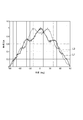
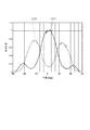
- FIG. 5 is a graph showing a simulation result of the light distribution in the light source unit 1 according to the embodiment of the present invention.
- the light receiver disposed on the emission surface 30 b of the prism plate 20 is directly above the light source 10.
- the relative luminous intensity ratio between the luminous intensity L1 measured in step 1 and the luminous intensity L2 measured immediately above the interval S1 between the light sources 10 can be made substantially equal when the light distribution angle is 0 degrees or in the vicinity of 0 degrees.
- FIG. 7 shows a simulation result of the light distribution in the light source unit 1 having another prism plate as another comparative example.
- the other prism plate has the same prism surface on the entrance surface and the exit surface. More specifically, this other prism plate has a prism surface similar to the incident side prism surface 40 having the plurality of incident side convex prism portions 42 of the prism plate 20 on the incident surface and the output surface. As shown in FIG.
- the light intensity LC3 measured just above the light source 10 and the light intensity LC4 measured just above the light source 10 The relative light intensity ratio of the light source unit 1 according to the embodiment of the present invention is larger than that of the light source unit 1 according to the embodiment of the present invention (FIG. 5). It can be seen that the brightness unevenness of the light emitted from the light can be suppressed and the light can be uniformly distributed.
- the prism plate 20 and the light source unit 1 according to the first embodiment of the present invention it is possible to uniformly distribute light while suppressing luminance unevenness of light emitted from a plurality of light sources. it can.
- the prism plate 60 according to the second embodiment of the present invention is different from the prism plate 20 according to the first embodiment of the present invention described above in that the incident-side prism surface 40 and the exit-side prism surface 50 are different from each other. Different incident-side prism surfaces 61 and output-side prism surfaces 62 are provided.
- configurations having the same or similar functions as those of the prism plate 20 according to the first embodiment of the present invention described above will be denoted by the same reference numerals, description thereof will be omitted, and different configurations will be described.
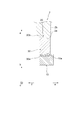
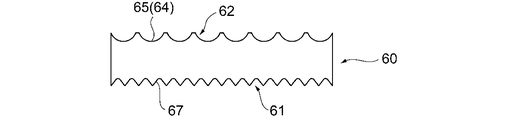
- FIG. 8 is a side view schematically showing the configuration of the prism plate 60 according to the second embodiment of the present invention.
- the incident-side prism surface 61 has a plurality of incident-side concave prism portions 63 that are concave from the incident surface 30a as incident-side prism portions.
- the plurality of incident-side concave prism portions 63 have the same or substantially the same shape.
- the contour in the cross section facing the extending direction (depth direction (arrow ef direction)) of the incident-side concave prism portion 63 has the same shape as the incident-side convex prism portion 42 described above.
- the exit-side prism surface 62 has a plurality of exit-side prism portions 64 that are concave from the exit surface 30b as the exit-side prism portion.
- a part of the plurality of emission-side prism parts 64 has a different shape from the rest of the plurality of emission-side prism parts 64.
- the exit-side prism surface 62 includes an exit-side concave prism portion 65 that is a part of the plurality of exit-side prism portions 64 and an exit-side pointed concave that is the remainder of the plurality of exit-side prism portions 64.
- a prism portion 66 is included in the prism plate 60, as shown in FIG. 8, the exit-side prism surface 62.
- the contour in the cross section facing the extending direction (depth direction (arrow ef direction)) of the exit-side concave prism portion 65 has the same shape as the above-described exit-side convex prism portion 52, and the exit-side cusp
- the contour in the cross section facing the extending direction (depth direction (arrow ef direction)) of the concave prism portion 66 has the same shape as the above-described emission-side convex convex prism portion 53.
- the prism plate 60 according to the second embodiment of the present invention having the above-described configuration also operates in the same manner as the prism plate 20 according to the first embodiment of the present invention described above, and is emitted from a plurality of light sources. It is possible to uniformly distribute light while suppressing unevenness in luminance of the light.
- the plurality of exit-side prism portions 51 may have the same shape.
- the exit-side prism surface 50 of the prism plate 20 may have only the exit-side ridged prism portion 53 as the exit-side prism portion 51.
- the exit-side prism surface 50 of the prism plate 20 includes only the exit-side convex prism portion 52 as the exit-side prism portion 51, and the entrance-side prism surface 40 of the prism plate 20.
- the incident-side prism portion 41 may have an incident-side ridge-shaped ridge prism portion 43 similar to the emission-side ridge-shaped ridge prism portion 53.
- the plurality of exit-side prism portions 64 may have the same shape.
- the exit-side prism surface 62 of the prism plate 60 may have only the exit-side sharpened prism portion 66 as the exit-side prism portion 64.
- the exit side prism surface 62 of the prism plate 60 has only the exit side concave prism portion 65 as the exit side prism portion 64, and the entrance side prism surface 61 of the prism plate 60. May have an incident side pointed concave prism portion 67 similar to the output side pointed concave prism portion 66 as the incident side prism portion.
- the prism plate 20 may have the incident-side prism surface 40 having the same configuration as the above-described exit-side prism surface 50.
- the exit-side prism surface 50 may have the same configuration as the above-described entrance-side prism surface 40.
- the prism plate 60 has an incident-side prism surface 61 having the same configuration as the above-described exit-side prism surface 62.
- the exit-side prism surface 62 may have the same configuration as the above-described entrance-side prism surface 61.
- it may be configured so that outgoing light is incident on a transparent substrate made of resin instead of glass, or it may be configured so that outgoing light is irradiated on a reflector, a diffuser, etc. instead of a transparent body. Good.
- SYMBOLS 1 Light source unit, 2 ... Glass substrate, 10 ... Light source, 10a ... Outgoing surface, 20, 60 ... Prism plate, 30 ... Base material, 30a ... Incident surface, 30b ... Outgoing surface, 40, 61 ... Incident side prism surface, DESCRIPTION OF SYMBOLS 41 ... Incident side prism part, 42 ... Incident side convex prism part, 43 ... Incident side sharp convex prism part, 50, 62 ... Outgoing side prism surface, 51, 64 ... Outgoing side prism part, 52 ... Outgoing side convex part Strip prism portion, 53... Exit side sharp convex prism portion, 54 .. top portion, 55 and 56... Straight line, 63... Incident side concave prism portion, 65. Strip prism portion, 67... Incident side pointed concave prism portion, S 1, S 2 .. spacing
Landscapes
- Physics & Mathematics (AREA)
- Engineering & Computer Science (AREA)
- General Engineering & Computer Science (AREA)
- General Physics & Mathematics (AREA)
- Optics & Photonics (AREA)
- Planar Illumination Modules (AREA)
- Optical Elements Other Than Lenses (AREA)
- Liquid Crystal (AREA)
Abstract
複数の光源から出射される光の輝度ムラを抑制して光を均一に配光することができるプリズムプレート及び光照射装置を提供する。 光源ユニット(光照射装置)(1)のプリズムプレート(20)は、入射面(30a)及び出射面(30b)を有する透光性の基材(30)と、入射面(30a)にプリズムを形成する、互いに並んで延びる透光性の複数の入射側プリズム面(40)と、プリズムプレート(20)は、出射面(30b)にプリズムを形成する、互いに並んで延びる透光性の複数の出射側プリズム面(50)とを備えている。入射側プリズム面(40)と出射側プリズム面(50)とは形状が互いに異なる。
Description
本発明は、プリズムプレート及び光照射装置に関する。
従来から、液晶パネルを照明するための光源ユニット(光照射装置)を有する液晶表示装置が広く知られている。このような液晶表示装置の光源ユニットの中には、導光板の端面側から光を入射して導光板を介して液晶パネルに光を入射する方式のものがあり光源として発光ダイオード等の点光源が間隔を有して配置されている。このような点光源を用いた光源ユニットでは、液晶パネルにおいて光源に対向する部分と光源間の部分で入射する光量が異なり、液晶パネル上で光強度の差(輝度ムラ)が発生し、縞模様等が発生していた。このため、従来から、このような輝度ムラの発生を抑制するための改良がなされている(例えば、特許文献1参照)。
このように、従来の光源ユニットは、液晶パネル上の輝度ムラの抑制を図っているが、従来の光源ユニットに対しては、更なる輝度ムラの抑制が求められていた。このように、従来の光源ユニットに対しては、複数の光源から出射される光の輝度ムラを抑制して光を均一に配光することができる構造が求められていた。
本発明は、上述の課題に鑑みてなされたものであり、その目的は、複数の光源から出射される光の輝度ムラを抑制して光を均一に配光することができるプリズムプレート及び光照射装置を提供することにある。
上記目的を達成するために、本発明に係るプリズムプレートは、一対の面を有する透光性の基材と、前記一対の面の一方の面においてプリズムを形成する、互いに並んで延びる透光性の複数の入射側プリズム部を有する入射側プリズム面と、前記一対の面の他方の面においてプリズムを形成する、互いに並んで延びる透光性の複数の出射側プリズム部を有する出射側プリズム面とを備え、前記入射側プリズム面と前記出射側プリズム面とは形状が互いに異なることを特徴とする。
本発明の一態様に係るプリズムプレートにおいて、前記入射側プリズム部は、前記一対の面の一方の面から凸である入射側プリズム部、及び前記一対の面の一方の面から凹である入射側プリズム部のいずれか一方であり、前記出射側プリズム部は、前記一対の面の他方の面から凸である出射側プリズム部、及び前記一対の面の他方の面から凹である出射側プリズム部のいずれか一方である。
本発明の一態様に係るプリズムプレートにおいて、前記入射側プリズム面において、前記複数の入射側プリズム部は互いに同一の形状を有しており、前記出射側プリズム面において、前記複数の出射側プリズム部は互いに同一の形状を有している。
本発明の一態様に係るプリズムプレートにおいて、前記入射側プリズム面において、前記複数の入射側プリズム部は互いに同一の形状を有しており、前記出射側プリズム面において、前記複数の出射側プリズム部のうちの一部と前記複数の出射側プリズム部のうち残りとは、互いに異なる形状を有している。
本発明の一態様に係るプリズムプレートにおいて、前記入射側プリズム部の延び方向に面する断面における輪郭は、曲面、多角形の一部、又は山形である。
本発明の一態様に係るプリズムプレートにおいて、前記出射側プリズム部の延び方向に面する断面における輪郭は、曲面、多角形の一部、又は山形である。
本発明の一態様に係るプリズムプレートにおいて、前記出射側プリズム部のうちの一部は、前記出射側プリズム部のうちの残りよりも尖っている。
本発明の一態様に係るプリズムプレートにおいて、前記出射側プリズム部のうちの一部の延び方向に面する断面における輪郭は、曲面又は多角形の一部であり、前記出射側プリズム部のうちの残りの延び方向に面する断面における輪郭は、山形である。
本発明の一態様に係るプリズムプレートにおいて、前記出射側プリズム部のうちの一部と、前記出射側プリズム部のうちの残りとは、所定の組み合わせで繰り返し並んでいる。
本発明の一態様に係るプリズムプレートにおいて、前記入射側プリズム部は、互いに隣接して又は所定の間隔を空けて互いに並んでいる。
本発明の一態様に係るプリズムプレートにおいて、前記出射側プリズム部は、互いに隣接して又は所定の間隔を空けて互いに並んでいる。
上記目的を達成するために、本発明に係る光照射装置は、並んで配置された複数の光源と、前記複数の光源の出射面に、前記入射側プリズム面が対向するように当接又は近接して配置された上述のいずれかのプリズムプレートとを備えることを特徴とする。
本発明の一態様に係る光照射装置において、前記複数の出射側プリズム部は、前記複数の光源の並び方向に直行する方向に延びており、前記複数の入射側プリズム部の延び方向と平行に延びている。
本発明に係るプリズムプレート及び光照射装置によれば、複数の光源から出射される光の輝度ムラを抑制して光を均一に配光することができる。
以下、本発明の実施の形態について図面を参照しながら説明する。
図1は、本発明の第1の実施の形態に係る光源ユニット1の構成を概略的に示す平面図であり、図2は、光源ユニット1の構成を概略的に示す側面図である。図3は、光源ユニット1の構成を概略的に示す部分拡大平面図であり、図4は、本発明の実施の形態に係るプリズムプレート20の構成を概略的に示す部分拡大斜視図である。
以下、説明の便宜上、図1における複数の光源10の出射方向を光源ユニット1の短手方向とし、便宜的に矢印ab方向とし、矢印a方向を上側、矢印b方向を下側とする。また、図1における複数の光源10の並び方向を光源ユニット1の長手方向とし、便宜的に矢印cd方向とし、矢印c方向を左側、矢印d方向を右側とする。また、図1における複数の光源10の並び方向に直交する方向を光源ユニット1の奥行き方向(紙面に対して垂直方向)とし、便宜的に矢印ef方向とし、矢印e方向を手前側、矢印f方向を奥側とする。以下の説明において、各部材の位置関係や方向を上下左右等を用いて説明するときは、あくまで図面における位置関係や方向を示し、実際の機器に組み込まれたときの位置関係や方向を示すものではない。
図1~4に示すように、本発明の実施の形態に係る光源ユニット(光照射装置)1は、図示しないフレキシブルプリント基板(以下、FPC基板ともいう。)上に並んで配置された複数の光源10と、複数の光源10の出射面10aに当接又は近接して配置されたプリズムプレート20とを備えている。プリズムプレート20は、一対の面(入射面30a,出射面30b)を有する透光性の基材30と、一対の面(入射面30a,出射面30b)の一方の面としての入射面30aにおいてプリズムを形成する入射側プリズム面40と、一対の面(入射面30a,出射面30b)の他方の面としての出射面30bにおいてプリズムを形成する出射側プリズム面50とを備えている。入射側プリズム面40は、互いに並んで延びる透光性の複数の入射側プリズム部41を有しており、出射側プリズム面50は、互いに並んで延びる透光性の複数の出射側プリズム部51を有している。入射側プリズム面40と出射側プリズム面50とは形状が互いに異なる。入射側プリズム面40と出射側プリズム面50とは互いに相似であってもよい。以下、光源ユニット1の構成について具体的に説明する。
光源ユニット1において、複数の光源10は、FPC基板の表面に設けられている(不図示)。プリズムプレート20は、複数の光源10の出射面10aに、入射側プリズム面40が対向するように当接又は近接して配置されており、具体的には、複数の光源10の出射面10aに面して設けられている。ガラス基板2は、複数の光源10の出射方向(光源ユニット1の短手方向(矢印ab方向))における上側(矢印a方向)に設けられている。
複数の光源10は、図1~4に示すように、複数の光源10の並び方向(光源ユニット1の長手方向(矢印cd方向))に所定の間隔S1を有して直線状又は略直線状に並んで配置されている。なお、複数の光源10の配置形態はこれに限らず、曲線状やジグザグ状に並んで配置されていてもよい。複数の光源10は、FPC基板の導電層(配線)に電気的に接続され、FPC基板の導電層(配線)を介して外部の制御モジュール等(図示せず)に接続される。
複数の光源10は、制御モジュール等から送信される指示信号に基づいて、出射面10aから光源ユニット1の短手方向(矢印ab方向)における上側(矢印a方向)に向かって光を照射するようになっている。複数の光源10は、例えば、LED(発光ダイオード)である。なお、複数の光源10はこれに限らず、LD(レーザダイオード)等の公知の発光素子であってもよく、赤色、緑色及び青色のLEDを各々有する発光素子であってもよい。
光源ユニット1において、プリズムプレート20は、図1~4に示すように、矩形板状又は略矩形板状に形成されている。プリズムプレート20は、複数の光源10から出射される光を透過するようになっており、透光性を有する材料、特に無色透明の合成樹脂により形成されている。プリズムプレート20は、例えば、ポリエチレンテレフタレート、ポリエチレンナフタレート、アクリル樹脂、ポリカーボネート系樹脂、ポリスチレン、ポリオレフィン、セルロースアセテート、耐候性塩化ビニル、活性エネルギー線硬化型樹脂等により形成されている。
プリズムプレート20は、矩形板状又は略矩形板状に形成された基材30と、基材30の入射面30a側に形成された入射側プリズム面40と、基材30の出射面30b側に形成された出射側プリズム面50とを有している。プリズムプレート20の入射面30aは、複数の光源10の出射面10aに対向して配置されている。プリズムプレート20の入射面30aは、複数の光源10の出射面10aに当接又は近接している。プリズムプレート20は、複数の光源10の出射面10aから照射される光を入射面30aにおいて受光し、出射面30bから出射するようになっている。
プリズムプレート20における基材30、入射側プリズム面40、出射側プリズム面50は、一体に形成されている。なお、プリズムプレート20の材料はこれに限らず、基材30としてポリエチレンテレフタレート、ポリエチレンナフタレート又はポリカーボネート系樹脂が用いられていてもよく、その入射面30a及び出射面30bに紫外線硬化性樹脂等により入射側プリズム面40、出射側プリズム面50が形成されていてもよい。また、入射側プリズム面40が一枚のシート状に形成されており、また、出射側プリズム面50が一枚のシート状に形成されており、これらのシートが基材30の入射面30a、出射面30bに夫々一枚又は複数貼り付けられてプリズムプレート20が形成されていてもよい。
入射側プリズム面40は、透光性の入射側プリズム部41を複数有しており、入射側プリズム面40において、入射側プリズム部41は互いに並んで延びている。入射側プリズム部41は、例えば、入射面30aから凸である入射側プリズム部41、及び入射面30aから凹である入射側プリズム部41のいずれか一方である。本実施の形態に係るプリズムプレート20においては、図3,4に示すように、入射側プリズム部41は、入射面30aから凸である。
出射側プリズム面50は、透光性の出射側プリズム部51を複数有しており、出射側プリズム面50において、出射側プリズム部51は互いに並んで延びている。出射側プリズム部51は、例えば、出射面30bから凸である出射側プリズム部51、及び出射面30bから凹である出射側プリズム部51のいずれか一方である。本実施の形態に係るプリズムプレート20においては、図3,4に示すように、出射側プリズム部51は、出射面30bから凸である。
また、入射側プリズム面40において、複数の入射側プリズム部41は互いに同一の形状を有していてもよく、複数の入射側プリズム部41のうちの一部と複数の入射側プリズム部41のうちの残りとは互いに異なる形状を有していてもよい。本実施の形態に係るプリズムプレート20においては、図3,4に示すように、複数の入射側プリズム部41は互いに同一又は略同一の形状を有している。以下、本実施の形態に係るプリズムプレート20の入射側プリズム部41を入射側凸条プリズム部42という。
また、出射側プリズム面50において、複数の出射側プリズム部51は互いに同一の形状を有していてもよく、複数の出射側プリズム部51のうちの一部と複数の出射側プリズム部51のうちの残りとは互いに異なる形状を有していてもよい。本実施の形態に係るプリズムプレート20においては、図3,4に示すように、複数の出射側プリズム部51のうちの一部は、複数の出射側プリズム部51のうちの残りとは異なる形状を有している。つまり、出射側プリズム面50は、複数の出射側プリズム部51のうちの一部である出射側凸条プリズム部52と、複数の出射側プリズム部51のうちの残りである出射側尖形凸条プリズム部53とを有している。
プリズムプレート20において、複数の入射側凸条プリズム部42は、各々入射面30aから複数の光源10の出射方向(光源ユニット1の短手方向(矢印ab方向))における下側(矢印b方向)に向かって凸であり、互いに複数の光源10の並び方向(光源ユニット1の長手方向(矢印cd方向))に平行又は略平行に並んでいる。また、複数の入射側凸条プリズム部42は、互いに複数の光源10の並び方向に直交又は略直交する方向(光源ユニット1の奥行き方向(矢印ef方向))に延びている。なお、複数の入射側凸条プリズム部42は、各々複数の光源10の並び方向(光源ユニット1の長手方向(矢印cd方向))に対して斜めに延びていてもよい。
入射側凸条プリズム部42は、例えば、入射側凸条プリズム部42の延び方向(奥行き方向(矢印ef方向))に面する断面における輪郭が曲面である。具体的には、図3及び4に示すように、入射側凸条プリズム部42は、延び方向(奥行き方向(矢印ef方向))に面する断面における輪郭が一定の曲率を有する円弧である。入射側凸条プリズム部42の長手方向(矢印cd方向)における幅は、短手方向(矢印ab方向)における高さよりも長くなっている。入射側凸条プリズム部42は、例えば、各々円柱形状若しくは略円柱形状の一部であり、レンチキュラーレンズやシリンドリカルレンズ等により形成される。
なお、入射側凸条プリズム部42の延び方向(奥行き方向(矢印ef方向))に面する断面における輪郭はこれに限らず、複数の曲率を有する曲面であってもよい。入射側凸条プリズム部42は、例えば、各々楕円柱形状若しくは略楕円柱形状の一部、又は蒲鉾形状若しくは略蒲鉾形状の一部であり、レンチキュラーレンズやシリンドリカルレンズにより形成される。また、入射側凸条プリズム部42における延び方向(奥行き方向(矢印ef方向))に面する断面における輪郭はこれに限らず、三角形や五角形、六角形等の多角形の一部であってもよい。入射側凸条プリズム部42における延び方向(奥行き方向(矢印ef方向))に面する断面は、例えば、円弧状に延びる多角形の一部である。入射側凸条プリズム部42の延び方向における断面の輪郭は、上述の形状に限らず、入射側凸条プリズム部42が入射面30aから突出するようになる他の形状であってもよい。
入射側凸条プリズム部42は、所定の間隔S2を空けて互いに並んで延びている。入射側凸条プリズム部42の長手方向(矢印cd方向)における幅は、所定の間隔S2の長手方向(矢印cd方向)における幅よりも長くなっている。なお、入射側凸条プリズム部42とこれに隣接する入射側凸条プリズム部42との間には、所定の間隔S2が設けられていなくてもよい。また、間隔S2は、奥行き方向(矢印ef方向)に一定の幅でなくてもよい。
プリズムプレート20において、複数の出射側凸条プリズム部52は、各々出射面30bから複数の光源10の出射方向(短手方向(矢印ab方向))における上側(矢印a方向)に向かって凸であり、互いに複数の光源10の並び方向(長手方向(矢印cd方向))に平行又は略平行に並んで延びている。また、複数の出射側凸条プリズム部52は、各々複数の光源10の並び方向に直交又は略直交する方向(奥行き方向(矢印ef方向))に延びており、また、複数の入射側凸条プリズム部42の延び方向(奥行き方向(矢印ef方向))と平行又は略平行に延びている。なお、複数の出射側凸条プリズム部52は、各々複数の光源10の並び方向(長手方向(矢印cd方向))に対して斜めに延びていてもよい。
出射側凸条プリズム部52は、例えば、出射側凸条プリズム部52の延び方向(奥行き方向(矢印ef方向))に面する断面における輪郭が曲面である。具体的には、図3及び4に示すように、出射側凸条プリズム部52は、延び方向(奥行き方向(矢印ef方向))に面する断面における輪郭が一定の曲率を有する円弧である。出射側凸条プリズム部52の長手方向(矢印cd方向)における幅は、短手方向(矢印ab方向)における高さよりも長くなっている。出射側凸条プリズム部52は、例えば、各々円柱形状若しくは略円柱形状の一部であり、レンチキュラーレンズやシリンドリカルレンズ等により形成される。
なお、出射側凸条プリズム部52の延び方向(奥行き方向(矢印ef方向))に面する断面における輪郭はこれに限らず、複数の曲率を有する曲面であってもよい。出射側凸条プリズム部52は、例えば、各々楕円柱形状若しくは略楕円柱形状の一部、又は蒲鉾形状若しくは略蒲鉾形状の一部であり、レンチキュラーレンズやシリンドリカルレンズにより形成される。また、出射側凸条プリズム部52における延び方向(奥行き方向(矢印ef方向))に面する断面における輪郭はこれに限らず、三角形や五角形、六角形等の多角形の一部であってもよい。出射側凸条プリズム部52における延び方向(奥行き方向(矢印ef方向))に面する断面は、例えば、円弧状に延びる多角形の一部である。出射側凸条プリズム部52は、入射側凸条プリズム部42と同一又は略同一であってもよく異なっていてもよい。出射側凸条プリズム部52の延び方向における断面の輪郭は、上述の形状に限らず、出射側凸条プリズム部52が出射面30bから突出するようになる他の形状であってもよい。
プリズムプレート20において、複数の出射側尖形凸条プリズム部53は、各々出射面30bから複数の光源10の出射方向(短手方向(矢印ab方向))における上側(矢印a方向)に向かって凸であり、夫々複数の光源10の並び方向(長手方向(矢印cd方向))に出射側凸条プリズム部52と交互に並んで延びている。すなわち、出射側尖形凸条プリズム部53は、互いに隣接する出射側凸条プリズム部52の間に形成されている。また、複数の出射側尖形凸条プリズム部53は、各々複数の光源10の並び方向に直交又は略直交する方向(奥行き方向(矢印ef方向))に延びており、また、複数の入射側凸条プリズム部42及び出射側凸条プリズム部52の延び方向(奥行き方向(矢印ef方向))と平行又は略平行に延びている。なお、複数の出射側尖形凸条プリズム部53は、各々複数の光源10の並び方向(長手方向(矢印cd方向))に対して斜めに延びていてもよい。出射側凸条プリズム部52と出射側尖形凸条プリズム部53との間は間隔を有していない。なお、出射側凸条プリズム部52と出射側尖形凸条プリズム部53との間はこれに限らず所定の間隔を有していてもよい。
複数の出射側尖形凸条プリズム部53は、各々出射側凸条プリズム部52よりも尖って形成されている。例えば、複数の出射側尖形凸条プリズム部53の長手方向(矢印cd方向)における幅は、各々複数の出射側凸条プリズム部52の長手方向(矢印cd方向)における幅よりも小さくなっている。また、複数の出射側尖形凸条プリズム部53における複数の光源10の出射方向(短手方向(矢印ab方向))の高さは、各々複数の出射側凸条プリズム部52における複数の光源10の出射方向(短手方向(矢印ab方向))の高さよりも高くなっている。
出射側尖形凸条プリズム部53は、例えば、出射側尖形凸条プリズム部53の延び方向(奥行き方向(矢印ef方向))に面する断面における輪郭が山形である。具体的には、図3及び4に示すように、出射側尖形凸条プリズム部53は、各々出射側尖形凸条プリズム部53の延び方向(奥行き方向(矢印ef方向))に面する断面における輪郭における頂部54が曲線である。出射側尖形凸条プリズム部53は、各々出射側尖形凸条プリズム部53の延び方向(奥行き方向(矢印ef方向))に面する断面における輪郭が頂部54に続く互いに対向する一対の傾斜する直線55,56を有している。一対の傾斜する直線55,56は、各々複数の光源10の出射方向(短手方向(矢印ab方向))における下側(矢印b方向)に向かうに連れて離れる方向に傾斜している。一対の傾斜する直線55,56がなす角度は鋭角である。
なお、出射側尖形凸条プリズム部53の頂部54はこれに限らず、一対の傾斜する直線55,56が交わる直線であってもよい。また、一対の傾斜する直線55,56がなす角度はこれに限らず、直角であってもよく、鈍角であってもよい。また、出射側尖形凸条プリズム部53における延び方向(奥行き方向(矢印ef方向))に面する断面における輪郭はこれに限らず、三角形や五角形、六角形等の多角形の一部であってもよい。複数の出射側尖形凸条プリズム部53は、例えば、三角柱形状又は略三角柱形状のプリズムレンズ等により形成される。
プリズムプレート20の出射面30bには、ガラス基板2が対向して配置されている。プリズムプレート20の出射面30bは、ガラス基板2の端面2aに当接又は近接している。ガラス基板2は、プリズムプレート20の出射面30bから出射される光をガラス基板2の端面2aにおいて受光し、ガラス基板2の出射面2bから出射するようになっている。そして、その後、ガラス基板2の出射面2bから出射される光は、液晶パネル(図示せず)に入射するようになっている。
このように、本発明の実施の形態に係る光源ユニット1では、複数の光源10の出射面10aに当接又は近接して配置された、入射側プリズム面40の入射側凸条プリズム部42、出射側プリズム面50の出射側凸条プリズム部52及び出射側尖形凸条プリズム部53を有するプリズムプレート20を備えている。プリズムプレート20において、複数の光源10からの入射光は、プリズムプレート20の出射面30bに光が均一に届くように、R形状の入射側凸条プリズム部42により拡散される。そして、プリズムプレート20の出射光は、出射側凸条プリズム部52を介して拡散され、また、出射側尖形凸条プリズム部53を介して集光される(立ち上げられる)。これにより、出射側凸条プリズム部52を介して拡散されて光の均一化が図られても、隣接する光源10の間の光は弱くなるが、出射側尖形凸条プリズム部53による集光により、この隣接する光源10の間の輝度が高められる。このため、複数の光源10から入射される光は、プリズムプレート20を介して均一な光となってガラス基板2から出射される。
図5は、本発明の実施の形態に係る光源ユニット1における配光分布のシミュレーション結果を示すグラフである。本発明の実施の形態に係る光源ユニット1では、図5に示す光源ユニット1における配光分布のシミュレーション結果のように、プリズムプレート20の出射面30bに配置された受光器において、光源10の直上で測定した光度L1と光源10の間の間隔S1の直上で測定した光度L2との相対光度比を、配光角度が0度又は0度近傍において、略同等にすることができる。
従って、本発明の実施の形態に係る光源ユニット1では、図6に示す比較例としてのプリズムプレート20を有しない光源ユニット1における配光分布のシミュレーション結果における光源10の直上で測定した光度LC1と光源10の間の間隔S1の直上で測定した光度LC2との相対光度比よりも相対光度比を小さくすることができるため、複数の光源10から出射される光の輝度ムラを抑制して光を均一に配光することができる。
また、図7は、他の比較例としての他のプリズムプレートを有する光源ユニット1における配光分布のシミュレーション結果を示している。この他のプリズムプレートは、入射面及び出射面に同一のプリズム面を有している。より具体的には、この他のプリズムプレートは、プリズムプレート20の複数の入射側凸条プリズム部42を有する入射側プリズム面40と同様のプリズム面を入射面及び出射面に有している。図7に示すように、この入射面及び出射面に同一のR形状のプリズム面を有する比較例においては、光源10の直上で測定した光度LC3と光源10の間の直上で測定した光度LC4との相対光度比が、本発明の実施の形態に係る光源ユニット1のもの(図5)よりも大きく、この比較例よりも、本発明の実施の形態に係る光源ユニット1は、複数の光源10から出射される光の輝度ムラを抑制して光を均一に配光することができることが分かる。
このように、本発明の第1の実施の形態に係るプリズムプレート20及び光源ユニット1によれば、複数の光源から出射される光の輝度ムラを抑制して光を均一に配光することができる。
次いで、本発明の第2の実施の形態に係るプリズムプレート60について説明する。本発明の第2の実施の形態に係るプリズムプレート60は、上述の本発明の第1の実施の形態に係るプリズムプレート20に対して、入射側プリズム面40及び出射側プリズム面50とは夫々異なる入射側プリズム面61及び出射側プリズム面62を有している。以下、上述の本発明の第1の実施の形態に係るプリズムプレート20と同一又は類似する機能を有する構成については同一の符号を付してその説明を省略し、異なる構成について説明する。
図8は、本発明の第2の実施の形態に係るプリズムプレート60の構成を概略的に示す側面図である。プリズムプレート60においては、図8に示すように、入射側プリズム面61は、入射側プリズム部として入射面30aから内部に凹の入射側凹条プリズム部63を複数有している。複数の入射側凹条プリズム部63は、互いに同一又は略同一の形状を有している。入射側凹条プリズム部63の延び方向(奥行き方向(矢印ef方向))に面する断面における輪郭は、上述の入射側凸条プリズム部42と同様の形状を有している。
また、プリズムプレート60においては、図8に示すように、出射側プリズム面62は、出射側プリズム部として出射面30bから内部に凹の出射側プリズム部64を複数有している。プリズムプレート60においては、図8に示すように、複数の出射側プリズム部64のうちの一部は、複数の出射側プリズム部64のうちの残りとは異なる形状を有している。つまり、出射側プリズム面62は、複数の出射側プリズム部64のうちの一部である出射側凹条プリズム部65と、複数の出射側プリズム部64のうちの残りである出射側尖形凹条プリズム部66とを有している。出射側凹条プリズム部65の延び方向(奥行き方向(矢印ef方向))に面する断面における輪郭は、上述の出射側凸条プリズム部52と同様の形状を有しており、出射側尖形凹条プリズム部66の延び方向(奥行き方向(矢印ef方向))に面する断面における輪郭は、上述の出射側尖形凸条プリズム部53と同様の形状を有している。
上述の構成を有する本発明の第2の実施の形態に係るプリズムプレート60においても、上述した本発明の第1の実施の形態に係るプリズムプレート20と同様に作用し、複数の光源から出射される光の輝度ムラを抑制して光を均一に配光することができる。
次いで、本発明の第1の実施の形態に係るプリズムプレート20の変形例を示す。上述したように、出射側プリズム面50において、複数の出射側プリズム部51は互いに同一の形状を有していてもよい。例えば、図9に示すように、プリズムプレート20の出射側プリズム面50は、出射側プリズム部51として、出射側尖形凸条プリズム部53のみを有していてもよい。また、図10に示すように、プリズムプレート20の出射側プリズム面50は、出射側プリズム部51として、出射側凸条プリズム部52のみを有しており、プリズムプレート20の入射側プリズム面40は、入射側プリズム部41として、出射側尖形凸条プリズム部53と同様の入射側尖形凸条プリズム部43を有していてもよい。
次いで、本発明の第2の実施の形態に係るプリズムプレート60の変形例を示す。上述したように、出射側プリズム面62において、複数の出射側プリズム部64は互いに同一の形状を有していてもよい。例えば、図11に示すように、プリズムプレート60の出射側プリズム面62は、出射側プリズム部64として、出射側尖形凹条プリズム部66のみを有していてもよい。また、図12に示すように、プリズムプレート60の出射側プリズム面62は、出射側プリズム部64として、出射側凹条プリズム部65のみを有しており、プリズムプレート60の入射側プリズム面61は、入射側プリズム部として、出射側尖形凹条プリズム部66と同様の入射側尖形凹条プリズム部67を有していてもよい。
また、上述の本発明の第1の実施の形態に係るプリズムプレート20の変形例として、プリズムプレート20は、入射側プリズム面40が上述の出射側プリズム面50と同様の構成となっていてもよく、出射側プリズム面50が上述の入射側プリズム面40と同様の構成となっていてもよい。同様に、上述の本発明の第2の実施の形態に係るプリズムプレート60の変形例として、プリズムプレート60は、入射側プリズム面61が上述の出射側プリズム面62と同様の構成となっていてもよく、出射側プリズム面62が上述の入射側プリズム面61と同様の構成となっていてもよい。
以上、本発明の実施の形態について説明したが、本発明は上記実施の形態に限定されるものではなく、本発明の概念及び請求の範囲に含まれるあらゆる態様を含む。また、上述した課題及び効果の少なくとも一部を奏するように、各構成を適宜選択的に組み合わせてもよい。例えば、上記実施の形態における、各構成要素の形状、材料、配置、サイズ等は、本発明の具体的使用態様によって適宜変更され得る。また、上記実施の形態における光源ユニット1は、出射光をガラス基板2に入射するように構成されているが、本発明はこれに限定されない。例えば、ガラスに代えて樹脂からなる透明基板に出射光を入射するように構成してもよいし、透明体に代えて反射体や、拡散体などに出射光を照射するように構成してもよい。
1…光源ユニット、2…ガラス基板、10…光源、10a…出射面、20,60…プリズムプレート、30…基材、30a…入射面、30b…出射面、40,61…入射側プリズム面、41…入射側プリズム部、42…入射側凸条プリズム部、43…入射側尖形凸条プリズム部、50,62…出射側プリズム面、51,64…出射側プリズム部、52…出射側凸条プリズム部、53…出射側尖形凸条プリズム部、54…頂部、55,56…直線、63…入射側凹条プリズム部、65…出射側凹条プリズム部、66…出射側尖形凹条プリズム部、67…入射側尖形凹状プリズム部、S1,S2…間隔
Claims (13)
- 一対の面を有する透光性の基材と、
前記一対の面の一方の面においてプリズムを形成する、互いに並んで延びる透光性の複数の入射側プリズム部を有する入射側プリズム面と、
前記一対の面の他方の面においてプリズムを形成する、互いに並んで延びる透光性の複数の出射側プリズム部を有する出射側プリズム面とを備え、
前記入射側プリズム面と前記出射側プリズム面とは形状が互いに異なることを特徴とするプリズムプレート。 - 前記入射側プリズム部は、前記一対の面の一方の面から凸である入射側プリズム部、及び前記一対の面の一方の面から凹である入射側プリズム部のいずれか一方であり、
前記出射側プリズム部は、前記一対の面の他方の面から凸である出射側プリズム部、及び前記一対の面の他方の面から凹である出射側プリズム部のいずれか一方であることを特徴とする請求項1項記載のプリズムプレート。 - 前記入射側プリズム面において、前記複数の入射側プリズム部は互いに同一の形状を有しており、
前記出射側プリズム面において、前記複数の出射側プリズム部は互いに同一の形状を有していることを特徴とする請求項1又は2記載のプリズムプレート。 - 前記入射側プリズム面において、前記複数の入射側プリズム部は互いに同一の形状を有しており、
前記出射側プリズム面において、前記複数の出射側プリズム部のうちの一部と前記複数の出射側プリズム部のうち残りとは、互いに異なる形状を有していることを特徴とする請求項1又は2記載のプリズムプレート。 - 前記入射側プリズム部の延び方向に面する断面における輪郭は、曲面、多角形の一部、又は山形であることを特徴とする請求項3又は4記載のプリズムプレート。
- 前記出射側プリズム部の延び方向に面する断面における輪郭は、曲面、多角形の一部、又は山形であることを特徴とする請求項3又は4記載のプリズムプレート。
- 前記出射側プリズム部のうちの一部は、前記出射側プリズム部のうちの残りよりも尖っていることを特徴とする請求項4記載のプリズムプレート。
- 前記出射側プリズム部のうちの一部の延び方向に面する断面における輪郭は、曲面又は多角形の一部であり、
前記出射側プリズム部のうちの残りの延び方向に面する断面における輪郭は、山形であることを特徴とする請求項7記載のプリズムプレート。 - 前記出射側プリズム部のうちの一部と、前記出射側プリズム部のうちの残りとは、所定の組み合わせで繰り返し並んでいることを特徴とする請求項4,7,8のいずれか1項記載のプリズムプレート。
- 前記入射側プリズム部は、互いに隣接して又は所定の間隔を空けて互いに並んでいることを特徴とする請求項1乃至9のいずれか1項記載のプリズムプレート。
- 前記出射側プリズム部は、互いに隣接して又は所定の間隔を空けて互いに並んでいることを特徴とする請求項1乃至10のいずれか1項記載のプリズムプレート。
- 並んで配置された複数の光源と、
前記複数の光源の出射面に、前記入射側プリズム面が対向するように当接又は近接して配置された請求項1乃至11のいずれか1項記載のプリズムプレートと
を備えることを特徴とする光照射装置。 - 前記複数の出射側プリズム部は、前記複数の光源の並び方向に直行する方向に延びており、前記複数の入射側プリズム部の延び方向と平行に延びていることを特徴とする請求項12記載の光照射装置。
Applications Claiming Priority (2)
| Application Number | Priority Date | Filing Date | Title |
|---|---|---|---|
| JP2018095576A JP6850765B2 (ja) | 2018-05-17 | 2018-05-17 | プリズムプレート及び光照射装置 |
| JP2018-095576 | 2018-05-17 |
Publications (1)
| Publication Number | Publication Date |
|---|---|
| WO2019220870A1 true WO2019220870A1 (ja) | 2019-11-21 |
Family
ID=68540142
Family Applications (1)
| Application Number | Title | Priority Date | Filing Date |
|---|---|---|---|
| PCT/JP2019/016942 Ceased WO2019220870A1 (ja) | 2018-05-17 | 2019-04-22 | プリズムプレート及び光照射装置 |
Country Status (2)
| Country | Link |
|---|---|
| JP (1) | JP6850765B2 (ja) |
| WO (1) | WO2019220870A1 (ja) |
Cited By (2)
| Publication number | Priority date | Publication date | Assignee | Title |
|---|---|---|---|---|
| WO2025190306A1 (zh) * | 2024-03-13 | 2025-09-18 | 苏州欧普照明有限公司 | 棱镜板及灯具 |
| US12422611B2 (en) * | 2022-04-20 | 2025-09-23 | Denso Corporation | Optical member |
Families Citing this family (1)
| Publication number | Priority date | Publication date | Assignee | Title |
|---|---|---|---|---|
| JP2025062246A (ja) * | 2023-10-02 | 2025-04-14 | 株式会社ジャパンディスプレイ | 液晶表示装置 |
Citations (8)
| Publication number | Priority date | Publication date | Assignee | Title |
|---|---|---|---|---|
| JP2005326819A (ja) * | 2004-04-12 | 2005-11-24 | Kuraray Co Ltd | 光拡散板 |
| JP2006100125A (ja) * | 2004-09-29 | 2006-04-13 | Fuji Photo Film Co Ltd | プリズムレンズフィルム及びこれを用いた平面型発光装置 |
| JP2007173031A (ja) * | 2005-12-22 | 2007-07-05 | Dainippon Printing Co Ltd | 光制御シート、面光源装置 |
| WO2008047794A1 (en) * | 2006-10-17 | 2008-04-24 | Kuraray Co., Ltd. | Lighting device and image display device using same |
| JP2009204781A (ja) * | 2008-02-27 | 2009-09-10 | Toppan Printing Co Ltd | レンズシート、ディスプレイ用光学シート及びそれを用いたバックライト・ユニット、ディスプレイ装置 |
| JP2010164657A (ja) * | 2009-01-13 | 2010-07-29 | Toppan Printing Co Ltd | 光学シート、バックライトユニット及びディスプレイ装置 |
| JP2013003320A (ja) * | 2011-06-15 | 2013-01-07 | Dainippon Printing Co Ltd | レンズシート、面光源装置、透過型表示装置、レンズシートの製造方法 |
| KR20170112530A (ko) * | 2016-03-31 | 2017-10-12 | 에스엘 주식회사 | 차량용 램프 |
Family Cites Families (1)
| Publication number | Priority date | Publication date | Assignee | Title |
|---|---|---|---|---|
| JP4694931B2 (ja) * | 2005-09-22 | 2011-06-08 | 大日本印刷株式会社 | 光制御シート、面光源装置 |
-
2018
- 2018-05-17 JP JP2018095576A patent/JP6850765B2/ja active Active
-
2019
- 2019-04-22 WO PCT/JP2019/016942 patent/WO2019220870A1/ja not_active Ceased
Patent Citations (8)
| Publication number | Priority date | Publication date | Assignee | Title |
|---|---|---|---|---|
| JP2005326819A (ja) * | 2004-04-12 | 2005-11-24 | Kuraray Co Ltd | 光拡散板 |
| JP2006100125A (ja) * | 2004-09-29 | 2006-04-13 | Fuji Photo Film Co Ltd | プリズムレンズフィルム及びこれを用いた平面型発光装置 |
| JP2007173031A (ja) * | 2005-12-22 | 2007-07-05 | Dainippon Printing Co Ltd | 光制御シート、面光源装置 |
| WO2008047794A1 (en) * | 2006-10-17 | 2008-04-24 | Kuraray Co., Ltd. | Lighting device and image display device using same |
| JP2009204781A (ja) * | 2008-02-27 | 2009-09-10 | Toppan Printing Co Ltd | レンズシート、ディスプレイ用光学シート及びそれを用いたバックライト・ユニット、ディスプレイ装置 |
| JP2010164657A (ja) * | 2009-01-13 | 2010-07-29 | Toppan Printing Co Ltd | 光学シート、バックライトユニット及びディスプレイ装置 |
| JP2013003320A (ja) * | 2011-06-15 | 2013-01-07 | Dainippon Printing Co Ltd | レンズシート、面光源装置、透過型表示装置、レンズシートの製造方法 |
| KR20170112530A (ko) * | 2016-03-31 | 2017-10-12 | 에스엘 주식회사 | 차량용 램프 |
Cited By (2)
| Publication number | Priority date | Publication date | Assignee | Title |
|---|---|---|---|---|
| US12422611B2 (en) * | 2022-04-20 | 2025-09-23 | Denso Corporation | Optical member |
| WO2025190306A1 (zh) * | 2024-03-13 | 2025-09-18 | 苏州欧普照明有限公司 | 棱镜板及灯具 |
Also Published As
| Publication number | Publication date |
|---|---|
| JP2019200358A (ja) | 2019-11-21 |
| JP6850765B2 (ja) | 2021-03-31 |
Similar Documents
| Publication | Publication Date | Title |
|---|---|---|
| KR101473552B1 (ko) | 면광원 장치, 액정 표시 장치 및 모바일 기기 | |
| KR100483209B1 (ko) | 면 광원장치 | |
| JP5202906B2 (ja) | 液晶表示装置 | |
| JP6220152B2 (ja) | 表示装置 | |
| JP5267531B2 (ja) | 導光パネル | |
| US8514349B2 (en) | Image display apparatus and backlight apparatus used therefor | |
| KR102222433B1 (ko) | 백라이트 유닛 및 이를 포함하는 표시 장치 | |
| WO2014017490A1 (ja) | 照明装置及び表示装置 | |
| WO2019220870A1 (ja) | プリズムプレート及び光照射装置 | |
| US8681293B2 (en) | Liquid crystal display device | |
| US10534126B2 (en) | Lighting device and display device | |
| WO2019021952A1 (ja) | 照明装置及び表示装置 | |
| WO2017170017A1 (ja) | 照明装置及び表示装置 | |
| JP5751988B2 (ja) | 照明ユニット及びこれを用いた表示装置 | |
| JP5533611B2 (ja) | バックライトユニット及びこれを用いた映像表示装置 | |
| JP5696799B2 (ja) | 面光源装置、液晶表示装置及びモバイル機器 | |
| KR102652314B1 (ko) | 백라이트 유닛 및 이를 포함하는 표시장치 | |
| WO2012144409A1 (ja) | 照明装置および表示装置 | |
| JP2008098190A (ja) | 面光源装置 | |
| TWM558920U (zh) | 背光模組及顯示裝置 | |
| JP2006134750A (ja) | バックライト | |
| KR102065361B1 (ko) | 도광판 및 이를 포함하는 액정 표시 장치 | |
| WO2011039896A1 (ja) | 光源モジュール、及びそれを備えた電子機器 | |
| KR20120012127A (ko) | 광원 유도 램프 | |
| JP5034984B2 (ja) | バックライト装置、及び表示装置 |
Legal Events
| Date | Code | Title | Description |
|---|---|---|---|
| 121 | Ep: the epo has been informed by wipo that ep was designated in this application |
Ref document number: 19804563 Country of ref document: EP Kind code of ref document: A1 |
|
| NENP | Non-entry into the national phase |
Ref country code: DE |
|
| 122 | Ep: pct application non-entry in european phase |
Ref document number: 19804563 Country of ref document: EP Kind code of ref document: A1 |