WO2019220564A1 - 油圧システム - Google Patents
油圧システム Download PDFInfo
- Publication number
- WO2019220564A1 WO2019220564A1 PCT/JP2018/018923 JP2018018923W WO2019220564A1 WO 2019220564 A1 WO2019220564 A1 WO 2019220564A1 JP 2018018923 W JP2018018923 W JP 2018018923W WO 2019220564 A1 WO2019220564 A1 WO 2019220564A1
- Authority
- WO
- WIPO (PCT)
- Prior art keywords
- valve
- increases
- electromagnetic proportional
- set value
- secondary pressure
- Prior art date
- Legal status (The legal status is an assumption and is not a legal conclusion. Google has not performed a legal analysis and makes no representation as to the accuracy of the status listed.)
- Ceased
Links
Images

Classifications
-
- E—FIXED CONSTRUCTIONS
- E02—HYDRAULIC ENGINEERING; FOUNDATIONS; SOIL SHIFTING
- E02F—DREDGING; SOIL-SHIFTING
- E02F9/00—Component parts of dredgers or soil-shifting machines, not restricted to one of the kinds covered by groups E02F3/00 - E02F7/00
- E02F9/20—Drives; Control devices
- E02F9/22—Hydraulic or pneumatic drives
-
- F—MECHANICAL ENGINEERING; LIGHTING; HEATING; WEAPONS; BLASTING
- F15—FLUID-PRESSURE ACTUATORS; HYDRAULICS OR PNEUMATICS IN GENERAL
- F15B—SYSTEMS ACTING BY MEANS OF FLUIDS IN GENERAL; FLUID-PRESSURE ACTUATORS, e.g. SERVOMOTORS; DETAILS OF FLUID-PRESSURE SYSTEMS, NOT OTHERWISE PROVIDED FOR
- F15B11/00—Servomotor systems without provision for follow-up action ; Circuits therefor
- F15B11/02—Systems essentially incorporating special features for controlling the speed or the actuating force of an output member
- F15B11/04—Systems essentially incorporating special features for controlling the speed or the actuating force of an output member for controlling the speed
- F15B11/042—Systems essentially incorporating special features for controlling the speed or the actuating force of an output member for controlling the speed by means in the feed line
-
- F—MECHANICAL ENGINEERING; LIGHTING; HEATING; WEAPONS; BLASTING
- F15—FLUID-PRESSURE ACTUATORS; HYDRAULICS OR PNEUMATICS IN GENERAL
- F15B—SYSTEMS ACTING BY MEANS OF FLUIDS IN GENERAL; FLUID-PRESSURE ACTUATORS, e.g. SERVOMOTORS; DETAILS OF FLUID-PRESSURE SYSTEMS, NOT OTHERWISE PROVIDED FOR
- F15B11/00—Servomotor systems without provision for follow-up action ; Circuits therefor
- F15B11/08—Servomotor systems without provision for follow-up action ; Circuits therefor with only one servomotor
-
- F—MECHANICAL ENGINEERING; LIGHTING; HEATING; WEAPONS; BLASTING
- F15—FLUID-PRESSURE ACTUATORS; HYDRAULICS OR PNEUMATICS IN GENERAL
- F15B—SYSTEMS ACTING BY MEANS OF FLUIDS IN GENERAL; FLUID-PRESSURE ACTUATORS, e.g. SERVOMOTORS; DETAILS OF FLUID-PRESSURE SYSTEMS, NOT OTHERWISE PROVIDED FOR
- F15B20/00—Safety arrangements for fluid actuator systems; Applications of safety devices in fluid actuator systems; Emergency measures for fluid actuator systems
Definitions
- the present invention relates to an electric positive control hydraulic system.
- Patent Document 1 discloses a hydraulic system 100 for a construction machine as shown in FIG.
- hydraulic oil is supplied from the variable displacement pump 110 to each hydraulic actuator 130 via the control valve 120.
- the control valve 120 increases the opening area of the passage for supplying the hydraulic oil to the hydraulic actuator 130 as the operation amount with respect to the operation unit (operation lever in FIG. 6) of the corresponding operation device 140 increases.
- the tilt angle of the pump 110 is adjusted by the regulator 111.
- the regulator 111 is connected to the first electromagnetic proportional valve 112.
- the first electromagnetic proportional valve 112 outputs a higher secondary pressure as the operation amount with respect to the operation unit of the operation device 140 increases. Thereby, the discharge flow rate of the pump 110 increases as the operation amount with respect to the operation unit of the operation device 140 increases.
- the hydraulic system 100 is provided with an unload valve 150 for releasing hydraulic oil discharged from the pump 110 to the tank during standby (when all the operation devices 140 are not operated).
- the unload valve 150 has a pilot port, and is configured such that the opening area decreases from the fully open state toward the fully closed state as the pilot pressure guided to the pilot port increases.
- the pilot port of the unload valve 150 is connected to the second electromagnetic proportional valve 160.
- the second electromagnetic proportional valve 160 outputs a higher secondary pressure as the operation amount with respect to the operation unit of the operation device 140 increases.
- an object of the present invention is to make it possible to operate a hydraulic actuator even when an electromagnetic proportional valve for an unloading valve fails and the secondary pressure of the electromagnetic proportional valve becomes zero.
- the present invention provides, from one aspect, an operation device that outputs an operation signal corresponding to an operation amount with respect to an operation unit, and a hydraulic actuator that operates as the operation signal output from the operation device increases.
- a control valve that increases the opening area of the passage for supplying oil, a variable displacement pump connected to the control valve by a supply line, and a higher secondary pressure as the operation signal output from the operation device increases.
- An unload valve having a pilot port, the higher the pilot pressure guided to the pilot port, the more the valve is moved from the fully open state to the fully closed state.
- the second electromagnetic proportional valve when the second electromagnetic proportional valve is normal, the secondary pressure of the second electromagnetic proportional valve is guided to the pilot port of the unload valve. Can be controlled.
- the second electromagnetic proportional valve fails and the secondary pressure of the second electromagnetic proportional valve becomes zero, the secondary pressure of the first electromagnetic proportional valve is led to the pilot port of the unload valve. Therefore, the opening area of the unload valve decreases as the operation signal increases. As a result, the discharge pressure of the pump increases in accordance with the operation amount with respect to the operation unit of the operation device, and the hydraulic actuator can be operated.
- the unload valve has an opening area that decreases from a maximum value to an intermediate value with a first slope when the pilot pressure increases from zero to a first set value, and the pilot pressure decreases from the first set value to the second set value.
- the opening area may be configured to decrease from the intermediate value to zero with a second inclination that is gentler than the first inclination when increasing to a set value.
- the opening area decreases from the maximum value to the intermediate value with a first slope, and the pilot pressure decreases from the first set value.
- the opening area decreases from the intermediate value to zero along a curve that protrudes upward with respect to a straight line having a second inclination that is gentler than the first inclination. It may be configured. According to this configuration, the opening area during standby is ensured without sacrificing the control gain in the range required for the control of the unload valve and without excessively increasing the spool stroke of the unload valve. it can. As a result, the power of the engine that drives the pump can be reduced during standby of the hydraulic system.
- an operation device that outputs an operation signal corresponding to an operation amount with respect to the operation unit, and a passage that supplies hydraulic oil to the hydraulic actuator as the operation signal output from the operation device increases.
- a control valve that increases the opening area, a variable displacement pump connected to the control valve by a supply line, and a first electromagnetic proportional valve that outputs a higher secondary pressure as the operation signal output from the operation device increases.
- a regulator that increases the tilt angle of the pump as the secondary pressure output from the first electromagnetic proportional valve increases, and an unload having a pilot port provided in an unload line that branches from the supply line And a second electric power that outputs a higher secondary pressure to the pilot port of the unload valve as the operation signal output from the valve and the operating device increases.
- a proportional valve wherein the unload valve changes between a first set value and a second set value greater than the first set value, the secondary pressure output from the second electromagnetic proportional valve.
- the opening area continuously changes between the fully open state and the fully closed state, the secondary pressure is smaller than the third set value smaller than the first set value and greater than the second set value.
- a hydraulic system configured so that the opening area becomes an intermediate value between a fully open state and a fully closed state when the value is equal to or greater than a fourth set value.
- the second electromagnetic proportional valve fails and the secondary pressure of the second electromagnetic proportional valve becomes zero, the opening area of the unload valve becomes an intermediate value, and the unload valve Functions as an aperture.
- the pump discharge pressure increases to some extent, and when the operating device is operated, the pump discharge pressure increases according to the operation amount, and the hydraulic actuator can be operated.
- the opening area of the unload valve becomes an intermediate value.
- the pump discharge pressure does not increase to the relief pressure during standby, and the pump discharge pressure can be prevented from becoming excessive.
- the hydraulic actuator can be operated even when the electromagnetic proportional valve for the unloading valve fails and the secondary pressure of the electromagnetic proportional valve becomes zero.
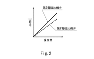
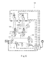
- FIG. 1 is a schematic configuration diagram of a hydraulic system according to a first embodiment of the present invention. It is a graph which shows the relationship between the operation amount with respect to the operation part of an operating device, and the secondary pressure of a 1st electromagnetic proportional valve and a 2nd electromagnetic proportional valve.
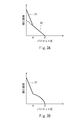
- FIG. 3A is a graph showing the relationship between the pilot pressure and the opening area of the unload valve in the first embodiment
- FIG. 3B is a graph showing the relationship between the pilot pressure and the opening area of the unload valve in the modification.
- It is a schematic block diagram of the hydraulic system which concerns on 2nd Embodiment of this invention. It is a graph which shows the relationship between the pilot pressure and opening area of an unload valve. It is a schematic block diagram of the hydraulic system of the conventional construction machine.
- FIG. 1 shows a hydraulic system 1A according to the first embodiment of the present invention.
- the hydraulic system 1A is mounted on, for example, a construction machine such as a hydraulic excavator or a hydraulic crane, a civil engineering machine, an agricultural machine, or an industrial machine.
- the hydraulic system 1 ⁇ / b> A includes a hydraulic actuator 24 and a main pump 21 that supplies hydraulic oil to the hydraulic actuator 24 via the control valve 3.
- a hydraulic actuator 24 and a main pump 21 that supplies hydraulic oil to the hydraulic actuator 24 via the control valve 3.
- the main pump 21 is a variable displacement pump whose tilt angle can be changed.
- the main pump 21 may be a swash plate pump or an oblique shaft pump.
- the tilt angle of the main pump 21 is adjusted by the regulator 22.
- the main pump 21 is connected to the control valve 3 by the supply line 11.
- the discharge pressure of the main pump 21 is kept below the relief pressure by the relief valve 12.
- the hydraulic actuator 24 is a double-acting cylinder, and the control valve 3 is connected to the hydraulic actuator 24 by a pair of supply / discharge lines 31.
- the hydraulic actuator 24 may be a single-acting cylinder, and the control valve 3 may be connected to the hydraulic actuator 24 by a single supply / discharge line 31.
- the hydraulic actuator 24 may be a hydraulic motor.
- the control valve 3 is moved from the neutral position to the first position (position where the hydraulic actuator 24 is operated in one direction) or the second position (position where the hydraulic actuator 24 is operated in the reverse direction) by operating the operation device 4. Can be switched.
- the control valve 3 is a hydraulic pilot type and has a pair of pilot ports.
- the control valve 3 may be an electromagnetic pilot type.
- the operation device 4 includes an operation unit 41 and outputs an operation signal corresponding to an operation amount with respect to the operation unit 41. That is, the operation signal output from the controller device 4 increases as the operation amount increases.
- the operation unit 41 is, for example, an operation lever, but may be a foot pedal or the like.
- the operation device 4 is a pilot operation valve that outputs a pilot pressure as an operation signal.
- the operating device 4 is connected to the pilot port of the control valve 3 by a pair of pilot lines 42.
- the controller device 4 may be an electric joystick that outputs an electrical signal as an operation signal.
- each pilot port of the control valve 3 is connected to the secondary pressure port of the electromagnetic proportional valve.
- the regulator 22 described above is connected to the secondary pressure port of the first electromagnetic proportional valve 6 by the secondary pressure line 62.
- a primary pressure port of the first electromagnetic proportional valve 6 is connected to the sub pump 23 by a primary pressure line 61.
- the discharge pressure of the sub pump 23 is maintained at a set pressure by the relief valve 15.
- the first electromagnetic proportional valve 6 is a direct proportional type that outputs a higher secondary pressure as the command current increases.
- the regulator 22 increases the tilt angle of the main pump 21 as the secondary pressure output from the first electromagnetic proportional valve 6 increases.
- the first electromagnetic proportional valve 6 is controlled by the control device 9.
- the control device 9 has a memory such as a ROM and a RAM and a CPU, and a program stored in the ROM is executed by the CPU.
- the control device 9 is electrically connected to a pressure sensor 91 provided in each of the pair of pilot lines 42 described above. However, in FIG. 1, only a part of the signal lines is drawn for simplification of the drawing.
- the pressure sensor 91 detects the pilot pressure output from the operating device 4.
- the control device 9 increases the command current supplied to the first electromagnetic proportional valve 6 as the pilot pressure output from the operation device 4 increases. That is, the first electromagnetic proportional valve 6 outputs a higher secondary pressure as the pilot pressure output from the operating device 4 increases. Thereby, the discharge flow rate of the main pump 21 increases as the operation amount with respect to the operation unit 41 of the operation device 4 increases.
- the unload line 13 branches from the supply line 11 described above.
- the unload line 13 is connected to a tank.
- the unload line 13 is provided with an unload valve 5A.
- the unloading valve 5A is a pilot type and has a pilot port 5c.
- the unload valve 5A is configured such that the opening area between the pump port 5a and the tank port 5b decreases from the fully open state to the fully closed state as the pilot pressure guided to the pilot port 5c increases. . That is, when the unload valve 5A is in a neutral state, the opening area is maximized.
- the opening area of the unload valve 5A decreases from the maximum value to the intermediate value with the first slope S1.
- the opening area decreases from the intermediate value to zero with a second slope S2 that is gentler than the first slope S1.
- the absolute value of the first gradient S1 is larger than the absolute value of the second gradient S2.
- the first set value ⁇ is 20% to 80% of the second set value ⁇ .
- the opening area of the unloading valve 5A does not necessarily reduce the pilot pressure linearly between the first set value ⁇ and the second set value ⁇ .
- the second slope S2 It may be reduced along a curve that is convex upward with respect to the straight line.
- the pilot port 5c of the unload valve 5A is connected to the secondary pressure port of the second electromagnetic proportional valve 7 via the high pressure selection valve 8.
- a primary pressure port of the second electromagnetic proportional valve 7 is connected to the sub pump 23 by a primary pressure line 71.
- the high pressure selection valve 8 has two input ports and one output port, and the pilot port 5c of the unloading valve 5A is connected to the output port of the high pressure selection valve 8 through the output line 83.
- One input port 8 is connected to the secondary pressure port of the second electromagnetic proportional valve 7 by the first input line 81.
- the other input port of the high pressure selection valve 8 is connected to the secondary pressure line 62 extending from the secondary pressure port of the first electromagnetic proportional valve 6 by the second input line 82. That is, the high pressure selection valve 8 selects the higher one of the secondary pressure output from the first electromagnetic proportional valve 6 and the secondary pressure output from the second electromagnetic proportional valve 7 to select the pilot port of the unload valve 5A. Guide to 5c.
- the second electromagnetic proportional valve 7 is a direct proportional type that outputs a higher secondary pressure as the command current increases.
- the second electromagnetic proportional valve 7 is controlled by the control device 9.
- the control device 9 increases the command current supplied to the second electromagnetic proportional valve 7 as the pilot pressure output from the operating device 4 increases. That is, the second electromagnetic proportional valve 7 outputs a higher secondary pressure as the pilot pressure output from the operating device 4 increases.
- the secondary pressure of the second electromagnetic proportional valve 7 is higher than the secondary pressure of the first electromagnetic proportional valve 6 for the same pilot pressure (operation signal) output from the operating device 4. It is set high.
- the second electromagnetic proportional valve 7 when the second electromagnetic proportional valve 7 is normal, the secondary pressure of the second electromagnetic proportional valve 7 is guided to the pilot port 5 c of the unload valve 5.
- the opening area of the valve 5A can be controlled.
- the second electromagnetic proportional valve 7 fails and the secondary pressure of the second electromagnetic proportional valve 7 becomes zero, the secondary pressure of the first electromagnetic proportional valve 6 is applied to the pilot port 5c of the unload valve 5A. Is guided. Therefore, the opening area of the unload valve 5A decreases as the operation signal increases. As a result, the discharge pressure of the main pump 21 increases according to the amount of operation with respect to the operation unit 41 of the operation device 4, and the hydraulic actuator 24 can be operated.
- the opening area of the unload valve 5A is sharply reduced at the beginning and gradually decreased from the middle. Therefore, the unload valve 5A is not sacrificed without sacrificing the control gain in the range required for control of the unload valve 5A (the range where the pilot pressure is between the first set value ⁇ and the second set value ⁇ ).
- the opening area during standby can be secured without making the spool stroke longer.
- the power of the engine (not shown) that drives the main pump 21 can be reduced during standby of the hydraulic system 1A. This effect can be obtained even in the case shown in FIG. 3B.
- the main pump 21 may be driven by an electric motor.
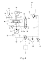
- FIG. 4 shows a hydraulic system 1B according to the second embodiment of the present invention.
- the same components as those in the first embodiment are denoted by the same reference numerals, and a duplicate description is omitted.
- the unload valve 5A which is a two-position valve
- an unload valve 5B which is a four-position valve
- the pilot port 5c of the unload valve 5B is connected to the secondary pressure port of the second electromagnetic proportional valve 7 by the secondary pressure line 72, and the second electromagnetic proportional valve 7 is unloaded valve 5B.
- the secondary pressure is output to the pilot port 5c.
- the secondary pressure of the second electromagnetic proportional valve 7 is equal to the secondary pressure of the first electromagnetic proportional valve 6 with respect to the same pilot pressure (operation signal) output from the operating device 4. It may be lower, lower, or higher as in the first embodiment.
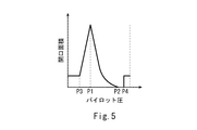
- the unload valve 5B has a second set value P2 in which the secondary pressure (pilot pressure) output from the second electromagnetic proportional valve 7 is larger than the first set value P1 and the first set value P1. Is configured such that the opening area between the pump port 5a and the tank port 5b continuously changes between the fully open state and the fully closed state.
- the opening area of the unload valve 5B decreases from the maximum value to zero as the secondary pressure of the second electromagnetic proportional valve 7 increases from the first set value P1 to the second set value P2.
- the unload valve 5B is equal to or higher than the fourth set value P4 larger than the second set value P2 when the secondary pressure of the second electromagnetic proportional valve 7 is equal to or smaller than the third set value P3 smaller than the first set value P1.
- the opening area is configured to be an intermediate value between the fully open state and the fully closed state.
- the intermediate value is 0.5 to 50% of the maximum value of the opening area.
- the intermediate value of the opening area when the secondary pressure of the second electromagnetic proportional valve 7 is the third set value P3 or less is the opening when the secondary pressure of the second electromagnetic proportional valve 7 is the fourth set value P4 or more. It may be equal to or different from the middle value of the area.
- the spool of the unload valve 5B slightly moves while the opening area of the unload valve 5B is maintained at the intermediate value. To do.
- the pilot pressure increases from the third set value P3 to the first set value P1
- the spool of the unload valve 5B moves so that the opening area of the unload valve 5B increases from the intermediate value to the maximum value.
- the pilot pressure increases from the first set value P1 to the second set value P2
- the spool of the unload valve 5B moves so that the opening area of the unload valve 5B decreases from the maximum value to zero.
- the spool of the unload valve 5B moves slightly while the opening area of the unload valve 5B is maintained at zero.
- the tank port 5b communicates with the pump port 5a again by the movement of the spool of the unload valve 5B, and the opening area of the unload valve 5B is maintained at an intermediate value.
- the opening area of the unload valve 5B becomes an intermediate value.
- the unload valve 5B functions as a throttle.
- the opening area of the unload valve 5B becomes an intermediate value.
- the discharge pressure of the main pump 21 does not increase to the relief pressure during standby, and the discharge pressure of the main pump 21 can be prevented from becoming excessive.
- the operation device 4 is operated, the discharge pressure of the main pump 21 increases according to the operation amount, and the hydraulic actuator 24 can be operated.
Landscapes
- Engineering & Computer Science (AREA)
- General Engineering & Computer Science (AREA)
- Physics & Mathematics (AREA)
- Fluid Mechanics (AREA)
- Mechanical Engineering (AREA)
- Chemical & Material Sciences (AREA)
- Analytical Chemistry (AREA)
- Mining & Mineral Resources (AREA)
- Civil Engineering (AREA)
- Structural Engineering (AREA)
- Fluid-Pressure Circuits (AREA)
Abstract
油圧システムは、操作装置と、操作装置から出力される操作信号が大きくなるほど油圧アクチュエータへ作動油を供給する通路の開口面積を増大させる制御弁と、可変容量型のポンプと、操作装置から出力される操作信号が大きくなるほど高い二次圧を出力する第1電磁比例弁および第2電磁比例弁と、第1電磁比例弁から出力される二次圧が高くなるほどポンプの傾転角を増大させるレギュレータと、パイロットポートに導かれるパイロット圧が高くなるほど全開状態から全閉状態に向かって開口面積が減少するアンロード弁と、第1電磁比例弁から出力される二次圧と第2電磁比例弁から出力される二次圧のうち高い方を選択してアンロード弁のパイロットポートへ導く高圧選択弁と、を備える。
Description
本発明は、電気ポジコン方式の油圧システムに関する。
従来から、建設機械や産業機械などでは、電気ポジコン方式の油圧システムが採用されている。例えば、特許文献1には、図6に示すような建設機械の油圧システム100が開示されている。
この油圧システム100では、可変容量型のポンプ110から制御弁120を介して各油圧アクチュエータ130へ作動油が供給される。制御弁120は、油圧アクチュエータ130へ作動油を供給する通路の開口面積を、対応する操作装置140の操作部(図6では操作レバー)に対する操作量が大きくなるほど増大させる。
ポンプ110の傾転角は、レギュレータ111によって調整される。レギュレータ111は、第1電磁比例弁112と接続されている。第1電磁比例弁112は、操作装置140の操作部に対する操作量が大きくなるほど高い二次圧を出力する。これにより、操作装置140の操作部に対する操作量が大きくなるほどポンプ110の吐出流量が増大する。
油圧システム100には、スタンバイ時(全ての操作装置140が操作されていない状態)にポンプ110から吐出される作動油をタンクへ逃すためのアンロード弁150が設けられている。アンロード弁150は、パイロットポートを有し、パイロットポートに導かれるパイロット圧が高くなるほど全開状態から全閉状態に向かって開口面積が減少するように構成されている。アンロード弁150のパイロットポートは、第2電磁比例弁160と接続されている。第2電磁比例弁160は、操作装置140の操作部に対する操作量が大きくなるほど高い二次圧を出力する。
しかしながら、図6に示す油圧システム100では、第2電磁比例弁160が故障した場合に、第2電磁比例弁160の二次圧がゼロになるか一次圧と等しくなる。第2電磁比例弁160の二次圧がゼロとなった場合には、アンロード弁150が全開状態となる。従って、操作装置140の操作部が操作されてもポンプ110の吐出圧が上昇せずに、油圧アクチュエータを作動させることができない。一方、第2電磁比例弁160の二次圧が一次圧と等しくなった場合は、アンロード弁150が全閉状態となる。従って、スタンバイ時にポンプ110の吐出圧が過大となる(リリーフ圧と等しくなる)。
そこで、本発明は、アンロード弁用の電磁比例弁が故障してその電磁比例弁の二次圧がゼロとなった場合でも油圧アクチュエータを作動させることができるようにすることを目的とする。
前記課題を解決するために、本発明は、一つの側面から、操作部に対する操作量に応じた操作信号を出力する操作装置と、前記操作装置から出力される操作信号が大きくなるほど油圧アクチュエータへ作動油を供給する通路の開口面積を増大させる制御弁と、供給ラインにより前記制御弁と接続された可変容量型のポンプと、前記操作装置から出力される操作信号が大きくなるほど高い二次圧を出力する第1電磁比例弁と、前記第1電磁比例弁から出力される二次圧が高くなるほど前記ポンプの傾転角を増大させるレギュレータと、前記供給ラインから分岐するアンロードラインに設けられた、パイロットポートを有するアンロード弁であって、前記パイロットポートに導かれるパイロット圧が高くなるほど全開状態から全閉状態に向かって開口面積が減少するアンロード弁と、前記操作装置から出力される操作信号が大きくなるほど高い二次圧を出力する第2電磁比例弁であって、同一の操作信号に対して当該第2電磁比例弁の二次圧が前記第1比例弁の二次圧よりも高く設定された第2電磁比例弁と、前記第1電磁比例弁から出力される二次圧と前記第2電磁比例弁から出力される二次圧のうち高い方を選択して前記アンロード弁のパイロットポートへ導く高圧選択弁と、を備える、油圧システムを提供する。
上記の構成によれば、第2電磁比例弁が正常な場合は、アンロード弁のパイロットポートには第2電磁比例弁の二次圧が導かれるために、第2電磁比例弁によってアンロード弁の開口面積を制御することができる。一方、第2電磁比例弁が故障して第2電磁比例弁の二次圧がゼロとなった場合は、アンロード弁のパイロットポートには第1電磁比例弁の二次圧が導かれる。従って、アンロード弁の開口面積は操作信号が大きくなるほど減少する。その結果、操作装置の操作部に対する操作量に応じてポンプの吐出圧が上昇し、油圧アクチュエータを作動させることができる。
前記アンロード弁は、パイロット圧がゼロから第1設定値まで上昇するときに開口面積が最大値から中間値まで第1の傾きで減少し、かつ、パイロット圧が前記第1設定値から第2設定値まで上昇するときに開口面積が前記中間値からゼロまで前記第1の傾きよりも緩やかな第2の傾きで減少するように構成されていてもよい。あるいは、前記アンロード弁は、パイロット圧がゼロから第1設定値まで上昇するときに開口面積が最大値から中間値まで第1の傾きで減少し、かつ、パイロット圧が前記第1設定値から第2設定値まで上昇するときに、開口面積が前記中間値からゼロまで前記第1の傾きよりも緩やかな第2の傾きの直線に対して上向きに凸となる曲線に沿って減少するように構成されていてもよい。この構成によれば、アンロード弁の制御上必要とされる範囲における制御ゲインを犠牲にすることなく、かつ、アンロード弁のスプールのストロークをあまり長くすることなく、スタンバイ時の開口面積を確保できる。その結果、油圧システムのスタンバイ時に、ポンプを駆動するエンジンの動力を低減することができる。
また、本発明は、別の側面から、操作部に対する操作量に応じた操作信号を出力する操作装置と、前記操作装置から出力される操作信号が大きくなるほど油圧アクチュエータへ作動油を供給する通路の開口面積を増大させる制御弁と、供給ラインにより前記制御弁と接続された可変容量型のポンプと、前記操作装置から出力される操作信号が大きくなるほど高い二次圧を出力する第1電磁比例弁と、前記第1電磁比例弁から出力される二次圧が高くなるほど前記ポンプの傾転角を増大させるレギュレータと、前記供給ラインから分岐するアンロードラインに設けられた、パイロットポートを有するアンロード弁と、前記操作装置から出力される操作信号が大きくなるほど高い二次圧を前記アンロード弁のパイロットポートへ出力する第2電磁比例弁と、を備え、前記アンロード弁は、前記第2電磁比例弁から出力される二次圧が第1設定値と前記第1設定値よりも大きな第2設定値との間で変化するときは開口面積が全開状態と全閉状態との間で連続的に変化し、前記二次圧が前記第1設定値よりも小さな第3設定値以下のときおよび前記第2設定値よりも大きな第4設定値以上のときは開口面積が全開状態と全閉状態との間の中間値となるように構成されている、油圧システムを提供する。
上記の構成によれば、第2電磁比例弁が故障して第2電磁比例弁の二次圧がゼロとなった場合は、アンロード弁の開口面積が中間値となって、アンロード弁が絞りとして機能する。その結果、操作装置が操作されないときでもポンプの吐出圧がある程度高くなるとともに、操作装置が操作されたときには操作量に応じてポンプの吐出圧が上昇し、油圧アクチュエータを作動させることができる。
さらに、上記の構成では、第2電磁比例弁が故障して第2電磁比例弁の二次圧が一次圧と等しくなった場合も、アンロード弁の開口面積が中間値となる。その結果、スタンバイ時にはポンプの吐出圧がリリーフ圧まで上昇せずに、ポンプの吐出圧が過大となることを防止することができる。
本発明によれば、アンロード弁用の電磁比例弁が故障してその電磁比例弁の二次圧がゼロとなった場合でも油圧アクチュエータを作動させることができる。
(第1実施形態)
図1に、本発明の第1実施形態に係る油圧システム1Aを示す。油圧システム1Aは、例えば、油圧ショベルや油圧クレーンのような建設機械、土木機械、農業機械または産業機械に搭載される。
図1に、本発明の第1実施形態に係る油圧システム1Aを示す。油圧システム1Aは、例えば、油圧ショベルや油圧クレーンのような建設機械、土木機械、農業機械または産業機械に搭載される。
具体的に、油圧システム1Aは、油圧アクチュエータ24と、油圧アクチュエータ24に制御弁3を介して作動油を供給する主ポンプ21を含む。図例では、油圧アクチュエータ24と制御弁3のセットが1つであるが、油圧アクチュエータ24と制御弁3のセットは複数設けられてもよい。
主ポンプ21は、傾転角が変更可能な、可変容量型のポンプである。主ポンプ21は、斜板ポンプであってもよいし、斜軸ポンプであってもよい。主ポンプ21の傾転角は、レギュレータ22により調整される。
主ポンプ21は、供給ライン11により制御弁3と接続されている。主ポンプ21の吐出圧は、リリーフ弁12によってリリーフ圧以下に保たれる。
本実施形態では、油圧アクチュエータ24が複動シリンダであり、制御弁3が一対の給排ライン31により油圧アクチュエータ24と接続されている。ただし、油圧アクチュエータ24が単動シリンダであり、制御弁3が1本の給排ライン31により油圧アクチュエータ24と接続されてもよい。あるいは、油圧アクチュエータ24は、油圧モータであってもよい。
制御弁3は、操作装置4が操作されることによって、中立位置から第1位置(油圧アクチュエータ24を一方向に作動させる位置)または第2位置(油圧アクチュエータ24を逆方向に作動させる位置)に切り換えられる。本実施形態では、制御弁3が油圧パイロット式であり、一対のパイロットポートを有する。ただし、制御弁3は、電磁パイロット式であってもよい。
操作装置4は、操作部41を有し、操作部41に対する操作量に応じた操作信号を出力する。つまり、操作装置4から出力される操作信号は、操作量が大きくなるほど大きくなる。操作部41は、例えば操作レバーであるが、フットペダルなどであってもよい。
本実施形態では、操作装置4が、操作信号としてパイロット圧を出力するパイロット操作弁である。このため、操作装置4が一対のパイロットライン42により制御弁3のパイロットポートと接続されている。そして、操作装置4から出力されるパイロット圧(操作信号)が大きくなるほど、制御弁3が油圧アクチュエータ24へ作動油を供給する通路の開口面積を増大させる。ただし、操作装置4は、操作信号として電気信号を出力する電気ジョイスティックであってもよい。この場合、制御弁3の各パイロットポートは、電磁比例弁の二次圧ポートと接続される。
上述したレギュレータ22は、二次圧ライン62により第1電磁比例弁6の二次圧ポートと接続されている。第1電磁比例弁6の一次圧ポートは、一次圧ライン61により副ポンプ23と接続されている。副ポンプ23の吐出圧は、リリーフ弁15によって設定圧に維持される。
第1電磁比例弁6は、指令電流が大きくなるほど高い二次圧を出力する正比例型である。レギュレータ22は、第1電磁比例弁6から出力される二次圧が高くなるほど主ポンプ21の傾転角を増大させる。
第1電磁比例弁6は、制御装置9により制御される。例えば、制御装置9は、ROMやRAMなどのメモリとCPUを有し、ROMに格納されたプログラムがCPUにより実行される。
制御装置9は、上述した一対のパイロットライン42のそれぞれに設けられた圧力センサ91と電気的に接続されている。ただし、図1では、図面の簡略化のために一部の信号線のみを描いている。
圧力センサ91は、操作装置4から出力されるパイロット圧を検出する。そして、制御装置9は、操作装置4から出力されるパイロット圧が大きくなるほど第1電磁比例弁6へ送給する指令電流を大きくする。つまり、第1電磁比例弁6は、操作装置4から出力されるパイロット圧が大きくなるほど高い二次圧を出力する。これにより、操作装置4の操作部41に対する操作量が大きくなるほど主ポンプ21の吐出流量が増大する。
上述した供給ライン11からはアンロードライン13が分岐している。アンロードライン13は、タンクへつながれている。アンロードライン13には、アンロード弁5Aが設けられている。
アンロード弁5Aは、パイロット式であり、パイロットポート5cを有する。そして、アンロード弁5Aは、パイロットポート5cに導かれるパイロット圧が高くなるほど全開状態から全閉状態に向かって、ポンプポート5aとタンクポート5bの間の開口面積が減少するように構成されている。つまり、アンロード弁5Aが中立状態のときは開口面積が最大となる。
本実施形態では、アンロード弁5Aが、図3Aに示すように、パイロット圧がゼロから第1設定値αまで上昇するときに開口面積が最大値から中間値まで第1の傾きS1で減少し、かつ、パイロット圧が第1設定値αから第2設定値βまで上昇するときに開口面積が前記中間値からゼロまで第1の傾きS1よりも緩やかな第2の傾きS2で減少するように構成されている。換言すれば、第1の傾きS1の絶対値は、第2の傾きS2の絶対値よりも大きい。例えば、第1設定値αは、第2設定値βの20%~80%である。ただし、アンロード弁5Aの開口面積は、パイロット圧が第1設定値αと第2設定値βの間で必ずしも直線的に減少する必要はなく、図3Bに示すように、第2の傾きS2の直線に対して上向きに凸となる曲線に沿って減少してもよい。
図1に戻って、アンロード弁5Aのパイロットポート5cは、高圧選択弁8を介して第2電磁比例弁7の二次圧ポートと接続されている。第2電磁比例弁7の一次圧ポートは、一次圧ライン71により副ポンプ23と接続されている。
より詳しくは、高圧選択弁8は、2つの入力ポートと1つの出力ポートを有し、アンロード弁5Aのパイロットポート5cが出力ライン83により高圧選択弁8の出力ポートと接続され、高圧選択弁8の1つの入力ポートが第1入力ライン81により第2電磁比例弁7の二次圧ポートと接続されている。さらに、高圧選択弁8のもう1つの入力ポートは、第2入力ライン82により、第1電磁比例弁6の二次圧ポートから延びる二次圧ライン62と接続されている。つまり、高圧選択弁8は、第1電磁比例弁6から出力される二次圧と第2電磁比例弁7から出力される二次圧のうち高い方を選択してアンロード弁5Aのパイロットポート5cへ導く。
第2電磁比例弁7は、指令電流が大きくなるほど高い二次圧を出力する正比例型である。第2電磁比例弁7は、制御装置9により制御される。
第1電磁比例弁6と同様に、制御装置9は、操作装置4から出力されるパイロット圧が大きくなるほど第2電磁比例弁7へ送給する指令電流を大きくする。つまり、第2電磁比例弁7は、操作装置4から出力されるパイロット圧が大きくなるほど高い二次圧を出力する。ただし、図2に示すように、操作装置4から出力される同一のパイロット圧(操作信号)に対し、第2電磁比例弁7の二次圧は第1電磁比例弁6の二次圧よりも高く設定されている。
このため、第2電磁比例弁7が正常な場合は、アンロード弁5のパイロットポート5cには第2電磁比例弁7の二次圧が導かれるために、第2電磁比例弁7によってアンロード弁5Aの開口面積を制御することができる。一方、第2電磁比例弁7が故障して第2電磁比例弁7の二次圧がゼロとなった場合は、アンロード弁5Aのパイロットポート5cには第1電磁比例弁6の二次圧が導かれる。従って、アンロード弁5Aの開口面積は操作信号が大きくなるほど減少する。その結果、操作装置4の操作部41に対する操作量に応じて主ポンプ21の吐出圧が上昇し、油圧アクチュエータ24を作動させることができる。
さらに、本実施形態では、図3Aに示すようにアンロード弁5Aの開口面積が最初は急激に、途中からはゆるやかに減少する。従って、アンロード弁5Aの制御上必要とされる範囲(パイロット圧が第1設定値αと第2設定値βの間の範囲)における制御ゲインを犠牲にすることなく、かつ、アンロード弁5Aのスプールのストロークをあまり長くすることなく、スタンバイ時の開口面積を確保できる。その結果、油圧システム1Aのスタンバイ時に、主ポンプ21を駆動するエンジン(図示せず)の動力を低減することができる。なお、この効果は、図3Bに示す場合でも得ることができる。ただし、主ポンプ21は、電動モータによって駆動されてもよい。
(第2実施形態)
図4に、本発明の第2実施形態に係る油圧システム1Bを示す。なお、本実施形態において、第1実施形態と同一構成要素には同一符号を付し、重複した説明は省略する。
図4に、本発明の第2実施形態に係る油圧システム1Bを示す。なお、本実施形態において、第1実施形態と同一構成要素には同一符号を付し、重複した説明は省略する。
第1実施形態では2位置弁であるアンロード弁5Aが採用されていたが、本実施形態では4位置弁であるアンロード弁5Bが採用されている。また、本実施形態では、アンロード弁5Bのパイロットポート5cが二次圧ライン72により第2電磁比例弁7の二次圧ポートと接続されており、第2電磁比例弁7がアンロード弁5Bのパイロットポート5cへ二次圧を出力する。
なお、本実施形態では、操作装置4から出力される同一のパイロット圧(操作信号)に対し、第2電磁比例弁7の二次圧は第1電磁比例弁6の二次圧と等しくてもよいし、それよりも低くてもよいし、第1実施形態と同様に高くてもよい。
アンロード弁5Bは、図5に示すように、第2電磁比例弁7から出力される二次圧(パイロット圧)が第1設定値P1と第1設定値P1よりも大きな第2設定値P2との間で変化するときは、ポンプポート5aとタンクポート5bの間の開口面積が全開状態と全閉状態との間で連続的に変化するように構成されている。本実施形態では、第2電磁比例弁7の二次圧が第1設定値P1から第2設定値P2へ上昇するにつれてアンロード弁5Bの開口面積が最大値からゼロまで減少する。
さらに、アンロード弁5Bは、第2電磁比例弁7の二次圧が第1設定値P1よりも小さな第3設定値P3以下のときおよび第2設定値P2よりも大きな第4設定値P4以上のときは、開口面積が全開状態と全閉状態との間の中間値となるように構成されている。例えば、中間値は、開口面積の最大値の0.5~50%である。なお、第2電磁比例弁7の二次圧が第3設定値P3以下のときの開口面積の中間値は、第2電磁比例弁7の二次圧が第4設定値P4以上のときの開口面積の中間値と等しくてもよいし、異なっていてもよい。
アンロード弁5Bのパイロットポート5cに導かれるパイロット圧がゼロから第3設定値P3まで上昇すると、アンロード弁5Bの開口面積が中間値に維持されたままでアンロード弁5Bのスプールが少しだけ移動する。パイロット圧が第3設定値P3から第1設定値P1まで上昇すると、アンロード弁5Bの開口面積が中間値から最大値まで増大するようにアンロード弁5Bのスプールが移動する。パイロット圧が第1設定値P1から第2設定値P2まで上昇すると、アンロード弁5Bの開口面積が最大値からゼロまで減少するようにアンロード弁5Bのスプールが移動する。パイロット圧が第2設定値P2から第4設定値P4まで上昇すると、アンロード弁5Bの開口面積がゼロに維持されたままでアンロード弁5Bのスプールが少しだけ移動する。パイロット圧が第4設定値P4以上となると、アンロード弁5Bのスプールの移動によってタンクポート5bがポンプポート5aと再度連通し、アンロード弁5Bの開口面積が中間値に維持される。
本実施形態の油圧システム1Bでは、第2電磁比例弁7が故障して第2電磁比例弁7の二次圧がゼロとなった場合は、アンロード弁5Bの開口面積が中間値となって、アンロード弁5Bが絞りとして機能する。その結果、操作装置4が操作されないときでも主ポンプ21の吐出圧がある程度高くなるとともに、操作装置4が操作されたときには操作量に応じて主ポンプ21の吐出圧が上昇し、油圧アクチュエータ24を作動させることができる。
さらに、本実施形態では、第2電磁比例弁7が故障して第2電磁比例弁7の二次圧が一次圧と等しくなった場合も、アンロード弁5Bの開口面積が中間値となる。その結果、スタンバイ時には主ポンプ21の吐出圧がリリーフ圧まで上昇せずに、主ポンプ21の吐出圧が過大となることを防止することができる。そして、操作装置4が操作されたときには操作量に応じて主ポンプ21の吐出圧が上昇し、油圧アクチュエータ24を作動させることができる。
(その他の実施形態)
本発明は上述した実施形態に限定されるものではなく、本発明の要旨を逸脱しない範囲で種々の変形が可能である。
本発明は上述した実施形態に限定されるものではなく、本発明の要旨を逸脱しない範囲で種々の変形が可能である。
1A,1B 油圧システム
11 供給ライン
21 主ポンプ
22 レギュレータ
24 油圧アクチュエータ
3 制御弁
4 操作装置
41 操作部
5A,5B アンロード弁
5c パイロットポート
6 第1電磁比例弁
7 第2電磁比例弁
8 高圧選択弁
11 供給ライン
21 主ポンプ
22 レギュレータ
24 油圧アクチュエータ
3 制御弁
4 操作装置
41 操作部
5A,5B アンロード弁
5c パイロットポート
6 第1電磁比例弁
7 第2電磁比例弁
8 高圧選択弁
Claims (4)
- 操作部に対する操作量に応じた操作信号を出力する操作装置と、
前記操作装置から出力される操作信号が大きくなるほど油圧アクチュエータへ作動油を供給する通路の開口面積を増大させる制御弁と、
供給ラインにより前記制御弁と接続された可変容量型のポンプと、
前記操作装置から出力される操作信号が大きくなるほど高い二次圧を出力する第1電磁比例弁と、
前記第1電磁比例弁から出力される二次圧が高くなるほど前記ポンプの傾転角を増大させるレギュレータと、
前記供給ラインから分岐するアンロードラインに設けられた、パイロットポートを有するアンロード弁であって、前記パイロットポートに導かれるパイロット圧が高くなるほど全開状態から全閉状態に向かって開口面積が減少するアンロード弁と、
前記操作装置から出力される操作信号が大きくなるほど高い二次圧を出力する第2電磁比例弁であって、同一の操作信号に対して当該第2電磁比例弁の二次圧が前記第1比例弁の二次圧よりも高く設定された第2電磁比例弁と、
前記第1電磁比例弁から出力される二次圧と前記第2電磁比例弁から出力される二次圧のうち高い方を選択して前記アンロード弁のパイロットポートへ導く高圧選択弁と、
を備える、油圧システム。 - 前記アンロード弁は、パイロット圧がゼロから第1設定値まで上昇するときに開口面積が最大値から中間値まで第1の傾きで減少し、かつ、パイロット圧が前記第1設定値から第2設定値まで上昇するときに開口面積が前記中間値からゼロまで前記第1の傾きよりも緩やかな第2の傾きで減少するように構成されている、請求項1に記載の油圧システム。
- 前記アンロード弁は、パイロット圧がゼロから第1設定値まで上昇するときに開口面積が最大値から中間値まで第1の傾きで減少し、かつ、パイロット圧が前記第1設定値から第2設定値まで上昇するときに、開口面積が前記中間値からゼロまで前記第1の傾きよりも緩やかな第2の傾きの直線に対して上向きに凸となる曲線に沿って減少するように構成されている、請求項1に記載の油圧システム。
- 操作部に対する操作量に応じた操作信号を出力する操作装置と、
前記操作装置から出力される操作信号が大きくなるほど油圧アクチュエータへ作動油を供給する通路の開口面積を増大させる制御弁と、
供給ラインにより前記制御弁と接続された可変容量型のポンプと、
前記操作装置から出力される操作信号が大きくなるほど高い二次圧を出力する第1電磁比例弁と、
前記第1電磁比例弁から出力される二次圧が高くなるほど前記ポンプの傾転角を増大させるレギュレータと、
前記供給ラインから分岐するアンロードラインに設けられた、パイロットポートを有するアンロード弁と、
前記操作装置から出力される操作信号が大きくなるほど高い二次圧を前記アンロード弁のパイロットポートへ出力する第2電磁比例弁と、を備え、
前記アンロード弁は、前記第2電磁比例弁から出力される二次圧が第1設定値と前記第1設定値よりも大きな第2設定値との間で変化するときは開口面積が全開状態と全閉状態との間で連続的に変化し、前記二次圧が前記第1設定値よりも小さな第3設定値以下のときおよび前記第2設定値よりも大きな第4設定値以上のときは開口面積が全開状態と全閉状態との間の中間値となるように構成されている、油圧システム。
Priority Applications (2)
| Application Number | Priority Date | Filing Date | Title |
|---|---|---|---|
| PCT/JP2018/018923 WO2019220564A1 (ja) | 2018-05-16 | 2018-05-16 | 油圧システム |
| CN201880077057.8A CN111373160B (zh) | 2018-05-16 | 2018-05-16 | 油压系统 |
Applications Claiming Priority (1)
| Application Number | Priority Date | Filing Date | Title |
|---|---|---|---|
| PCT/JP2018/018923 WO2019220564A1 (ja) | 2018-05-16 | 2018-05-16 | 油圧システム |
Publications (1)
| Publication Number | Publication Date |
|---|---|
| WO2019220564A1 true WO2019220564A1 (ja) | 2019-11-21 |
Family
ID=68539778
Family Applications (1)
| Application Number | Title | Priority Date | Filing Date |
|---|---|---|---|
| PCT/JP2018/018923 Ceased WO2019220564A1 (ja) | 2018-05-16 | 2018-05-16 | 油圧システム |
Country Status (2)
| Country | Link |
|---|---|
| CN (1) | CN111373160B (ja) |
| WO (1) | WO2019220564A1 (ja) |
Cited By (1)
| Publication number | Priority date | Publication date | Assignee | Title |
|---|---|---|---|---|
| CN115638151A (zh) * | 2022-09-08 | 2023-01-24 | 江苏徐工工程机械研究院有限公司 | 液压系统的控制方法和液压系统 |
Citations (1)
| Publication number | Priority date | Publication date | Assignee | Title |
|---|---|---|---|---|
| JP2004360898A (ja) * | 2003-05-15 | 2004-12-24 | Kobelco Contstruction Machinery Ltd | 作業機械の油圧制御装置 |
Family Cites Families (4)
| Publication number | Priority date | Publication date | Assignee | Title |
|---|---|---|---|---|
| JP3535667B2 (ja) * | 1996-08-24 | 2004-06-07 | コベルコ建機株式会社 | 建設機械の油圧駆動装置 |
| US7155909B2 (en) * | 2003-05-15 | 2007-01-02 | Kobelco Construction Machinery Co., Ltd. | Hydraulic controller for working machine |
| CN104302931B (zh) * | 2012-10-30 | 2016-06-08 | 川崎重工业株式会社 | 液压控制装置 |
| CN105926696B (zh) * | 2016-06-20 | 2017-12-29 | 浙江大学 | 一种挖掘机动臂势能分级回收及释放装置及其方法 |
-
2018
- 2018-05-16 CN CN201880077057.8A patent/CN111373160B/zh not_active Expired - Fee Related
- 2018-05-16 WO PCT/JP2018/018923 patent/WO2019220564A1/ja not_active Ceased
Patent Citations (1)
| Publication number | Priority date | Publication date | Assignee | Title |
|---|---|---|---|---|
| JP2004360898A (ja) * | 2003-05-15 | 2004-12-24 | Kobelco Contstruction Machinery Ltd | 作業機械の油圧制御装置 |
Cited By (1)
| Publication number | Priority date | Publication date | Assignee | Title |
|---|---|---|---|---|
| CN115638151A (zh) * | 2022-09-08 | 2023-01-24 | 江苏徐工工程机械研究院有限公司 | 液压系统的控制方法和液压系统 |
Also Published As
| Publication number | Publication date |
|---|---|
| CN111373160B (zh) | 2022-02-25 |
| CN111373160A (zh) | 2020-07-03 |
Similar Documents
| Publication | Publication Date | Title |
|---|---|---|
| CN110651127B (zh) | 油压系统 | |
| CN103827490B (zh) | 油压控制系统 | |
| US9932995B2 (en) | Hydraulic excavator drive system | |
| US6584770B2 (en) | Hydraulic drive system | |
| US10590963B2 (en) | Hydraulic excavator drive system | |
| US10370825B2 (en) | Hydraulic drive system of construction machine | |
| US10619632B2 (en) | Hydraulic drive system of construction machine | |
| JP6463649B2 (ja) | 建設機械の油圧駆動システム | |
| JP6757238B2 (ja) | 油圧駆動システム | |
| WO2018230642A1 (ja) | 油圧システム | |
| JP6799480B2 (ja) | 油圧システム | |
| JP6726127B2 (ja) | 油圧システム | |
| US8522541B2 (en) | Hydraulic circuit of winch for crane | |
| CN111373160B (zh) | 油压系统 | |
| CN110431317B (zh) | 油压系统 | |
| JP5946184B2 (ja) | 作業機械の油圧駆動装置 | |
| US10794380B2 (en) | Pump device | |
| JP2005299931A (ja) | 建設機械の油圧制御装置 | |
| WO2025234163A1 (ja) | 油圧システムおよび制御装置 | |
| JP6331010B2 (ja) | 油圧駆動装置 | |
| JP5110846B2 (ja) | ロードセンシング式油圧制御装置 | |
| WO2018178961A1 (ja) | 油圧システム | |
| JP2001227504A (ja) | 走行油圧制御装置 |
Legal Events
| Date | Code | Title | Description |
|---|---|---|---|
| 121 | Ep: the epo has been informed by wipo that ep was designated in this application |
Ref document number: 18918980 Country of ref document: EP Kind code of ref document: A1 |
|
| NENP | Non-entry into the national phase |
Ref country code: DE |
|
| 122 | Ep: pct application non-entry in european phase |
Ref document number: 18918980 Country of ref document: EP Kind code of ref document: A1 |
|
| NENP | Non-entry into the national phase |
Ref country code: JP |