WO2019220527A1 - ヘッドマウントディスプレイ、画像表示方法およびコンピュータプログラム - Google Patents
ヘッドマウントディスプレイ、画像表示方法およびコンピュータプログラム Download PDFInfo
- Publication number
- WO2019220527A1 WO2019220527A1 PCT/JP2018/018709 JP2018018709W WO2019220527A1 WO 2019220527 A1 WO2019220527 A1 WO 2019220527A1 JP 2018018709 W JP2018018709 W JP 2018018709W WO 2019220527 A1 WO2019220527 A1 WO 2019220527A1
- Authority
- WO
- WIPO (PCT)
- Prior art keywords
- image
- eye
- screen
- lens
- size
- Prior art date
- Legal status (The legal status is an assumption and is not a legal conclusion. Google has not performed a legal analysis and makes no representation as to the accuracy of the status listed.)
- Ceased
Links
Images





Classifications
-
- G—PHYSICS
- G02—OPTICS
- G02B—OPTICAL ELEMENTS, SYSTEMS OR APPARATUS
- G02B27/00—Optical systems or apparatus not provided for by any of the groups G02B1/00 - G02B26/00, G02B30/00
- G02B27/01—Head-up displays
- G02B27/017—Head mounted
- G02B27/0172—Head mounted characterised by optical features
-
- G—PHYSICS
- G09—EDUCATION; CRYPTOGRAPHY; DISPLAY; ADVERTISING; SEALS
- G09G—ARRANGEMENTS OR CIRCUITS FOR CONTROL OF INDICATING DEVICES USING STATIC MEANS TO PRESENT VARIABLE INFORMATION
- G09G3/00—Control arrangements or circuits, of interest only in connection with visual indicators other than cathode-ray tubes
- G09G3/20—Control arrangements or circuits, of interest only in connection with visual indicators other than cathode-ray tubes for presentation of an assembly of a number of characters, e.g. a page, by composing the assembly by combination of individual elements arranged in a matrix no fixed position being assigned to or needed to be assigned to the individual characters or partial characters
-
- H—ELECTRICITY
- H04—ELECTRIC COMMUNICATION TECHNIQUE
- H04N—PICTORIAL COMMUNICATION, e.g. TELEVISION
- H04N13/00—Stereoscopic video systems; Multi-view video systems; Details thereof
- H04N13/30—Image reproducers
- H04N13/327—Calibration thereof
-
- H—ELECTRICITY
- H04—ELECTRIC COMMUNICATION TECHNIQUE
- H04N—PICTORIAL COMMUNICATION, e.g. TELEVISION
- H04N13/00—Stereoscopic video systems; Multi-view video systems; Details thereof
- H04N13/30—Image reproducers
- H04N13/332—Displays for viewing with the aid of special glasses or head-mounted displays [HMD]
- H04N13/344—Displays for viewing with the aid of special glasses or head-mounted displays [HMD] with head-mounted left-right displays
-
- G—PHYSICS
- G02—OPTICS
- G02B—OPTICAL ELEMENTS, SYSTEMS OR APPARATUS
- G02B27/00—Optical systems or apparatus not provided for by any of the groups G02B1/00 - G02B26/00, G02B30/00
- G02B27/01—Head-up displays
- G02B27/0101—Head-up displays characterised by optical features
- G02B2027/0138—Head-up displays characterised by optical features comprising image capture systems, e.g. camera
-
- G—PHYSICS
- G02—OPTICS
- G02B—OPTICAL ELEMENTS, SYSTEMS OR APPARATUS
- G02B27/00—Optical systems or apparatus not provided for by any of the groups G02B1/00 - G02B26/00, G02B30/00
- G02B27/01—Head-up displays
- G02B27/0101—Head-up displays characterised by optical features
- G02B2027/014—Head-up displays characterised by optical features comprising information/image processing systems
-
- G—PHYSICS
- G02—OPTICS
- G02B—OPTICAL ELEMENTS, SYSTEMS OR APPARATUS
- G02B27/00—Optical systems or apparatus not provided for by any of the groups G02B1/00 - G02B26/00, G02B30/00
- G02B27/01—Head-up displays
- G02B27/0179—Display position adjusting means not related to the information to be displayed
- G02B2027/0187—Display position adjusting means not related to the information to be displayed slaved to motion of at least a part of the body of the user, e.g. head, eye
Definitions
- the present invention relates to data processing technology, and more particularly to a head mounted display, an image display method, and a computer program.
- HMD head-mounted display
- the position of the left panel and the position of the right panel may shift due to assembly errors, and the position of the left lens and the position of the right lens may shift. If the left and right panels or the left and right lenses are displaced, the user may not be able to obtain a correct stereoscopic effect, and the user may be tired. It is very expensive to reduce assembly errors in the manufacturing process of the HMD. For this reason, after manufacturing the HMD, the displacement of the panel or lens is measured, and a left-eye image and a right-eye image in which the drawing positions are shifted from each other may be created according to the displacement.
- the present invention has been made in view of the above problems, and one object is to provide a technique for efficiently absorbing assembly errors of the HMD or reducing the data transfer amount.
- a head-mounted display enlarges a left screen displaying a left-eye image, a right screen displaying a right-eye image, and a left-eye image displayed on the left screen.
- a left lens to be presented to the user a right lens to be displayed to the user by enlarging the right-eye image displayed on the right screen, a storage unit, an acquisition unit, and a control unit.
- the left screen has a part larger than the size of the left lens, the image for the left eye displayed in the area of the left screen exceeding the size of the left lens is not visually recognized by the user, and the right screen has a part larger than the size of the right lens.
- the storage unit displays the display start position of the left-eye image on the left screen and the right-eye image on the right screen.
- the display start position of the left eye image and the display start position of the right eye image are determined according to at least one of a shift between the left screen and the right screen and a shift between the left lens and the right lens. Different values are set, and the acquisition unit acquires an image for the left eye having a size corresponding to the size of the left lens and an image for the right eye having a size corresponding to the size of the right lens, which are images generated by an external device.
- the control unit Display the left-eye image acquired by the acquisition unit from the display start position of the left-eye image stored in the storage unit, and acquire from the display start position of the right-eye image in the right screen stored in the storage unit The right-eye image acquired by the unit is displayed.
- the head-mounted display includes a left screen that displays an image for the left eye, a right screen that displays an image for the right eye, a left lens that enlarges and displays the left-eye image displayed on the left screen, and a right screen A right lens that enlarges the displayed right-eye image and presents it to the user, a storage unit, a generation unit, and a control unit.
- the left screen has a part larger than the size of the left lens, the image for the left eye displayed in the area of the left screen exceeding the size of the left lens is not visually recognized by the user, and the right screen has a part larger than the size of the right lens.
- the storage unit displays the display start position of the left-eye image on the left screen and the right-eye image on the right screen.
- the display start position of the left eye image and the display start position of the right eye image are determined according to at least one of a shift between the left screen and the right screen and a shift between the left lens and the right lens. Different values are set, and the generation unit generates a left-eye image having a size corresponding to the size of the left lens and a right-eye image having a size corresponding to the size of the right lens, and the control unit is stored in the storage unit.
- the image for the left eye generated by the generation unit is displayed from the display start position of the image, and the image for the right eye generated by the generation unit is displayed from the display start position of the image for the right eye on the right screen stored in the storage unit. .
- Still another aspect of the present invention is an image display method.
- This method includes a left screen that displays a left-eye image, a right screen that displays a right-eye image, a left lens that enlarges the left-eye image displayed on the left screen and presents it to the user, and a right screen that is displayed on the right screen.
- the method is executed by a head-mounted display that includes a right lens for enlarging and presenting a right-eye image to a user and a storage unit, and the left screen has a portion larger than the size of the left lens, and the size of the left lens
- the left-eye image displayed in the area of the left screen exceeding the size of the left screen is not visible to the user, and the right screen has a portion larger than the size of the right lens and is displayed in the area of the right screen exceeding the size of the right lens.
- the right-eye image is not visually recognized by the user, and the storage unit stores the display start position of the left-eye image on the left screen and the display start position of the right-eye image on the right screen, and the display start position of the left-eye image and the right eye Image display
- the start position is an image generated by an external device with different values depending on at least one of the deviation between the left screen and the right screen and the deviation between the left lens and the right lens, and the size of the left lens
- the assembly error of the HMD can be efficiently absorbed or the data transfer amount can be reduced.
- HMD typically. It is a figure which shows the structure of HMD typically. It is a figure which shows the example of the assembly error of HMD. It is a figure which shows the size of a panel and the size of a lens. It is a figure which shows an example of an assembly error absorption process typically. It is a figure which shows typically the assembly error absorption process in an Example. It is a figure which shows the structure of the entertainment system of 1st Example. It is a figure which shows the structure of the entertainment system of 2nd Example. It is a figure which shows the structure of the entertainment system of 3rd Example.
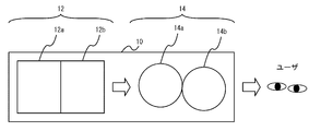
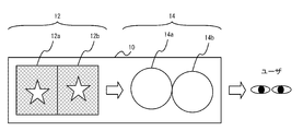
- FIG. 1 schematically shows the configuration of the HMD 10.
- the HMD 10 includes a left panel 12a and a right panel 12b that are collectively referred to as a panel 12, and a left lens 14a and a right lens 14b that are collectively referred to as a lens 14.
- the panel 12 includes a screen configured by, for example, a liquid crystal display (LCD) or an organic light-emitting diode (OLED).
- the left panel 12a includes a screen that displays an image to be presented to the user's left eye (hereinafter “left-eye image”), and the right panel 12b displays an image to be presented to the user's right eye (hereinafter “right-eye image”). Includes screens.
- LCD liquid crystal display
- OLED organic light-emitting diode
- the left lens 14a and the right lens 14b are, for example, convex lenses.
- the left lens 14a enlarges the left-eye image displayed on the left panel 12a and presents it to the user's left eye.
- the right lens 14b enlarges the image for the right eye displayed on the right panel 12b and presents it to the user's right eye. This provides the user with a large viewing angle.
- a parallax is provided between the left-eye image and the right-eye image, providing a stereoscopic effect to the user who views the left-eye image and the right-eye image at the same time.
- the HMD 10 presents a stereoscopic video to the user.
- FIG. 2 shows an example of assembly error of the HMD 10.
- the position of the left lens 14a and the position of the right lens 14b are shifted in the vertical direction.
- the deviation in the left-right direction is less likely to be a problem because it is offset by the adjustment of the interpupillary distance (Pupil Distance; PD) that differs for each user (the person wearing the HMD 10).
- PD interpupillary distance
- the size of each of the left panel 12a and the right panel 12b is 960 horizontal by 1080 vertical pixels (horizontal 8: vertical 9).
- a general-purpose lens is usually circular.
- the size of the left panel 12a is larger than the size of the left lens 14a, and similarly, the size of the right panel 12b is larger than the size of the right lens 14b.
- the diameter of the left lens 14a corresponds to the length (960 pixels) in the short direction of the left panel 12a (same in the embodiment).
- the diameter of the right lens 14b is the same (960 pixels).
- the light that does not pass through the lens 14 out of the light output from the panel 12 does not reach the user's eyes. Therefore, the image displayed in the area of the left panel 12a exceeding the size of the left lens 14a is not visible to the user and is not visually recognized by the user. Similarly, the image displayed in the area of the right panel 12b exceeding the size of the right lens 14b is not visually recognized by the user.
- the area of the panel 12 that exceeds the size of the lens 14 can be said to be an area of the panel 12 that is not covered by the lens 14 and can be said to be an area of the panel 12 that is outside the range of the user's field of view through the lens. It can also be said that the region of the panel 12 is invisible.
- the light that passes through the lens 14 out of the light output from the panel 12 reaches the eyes of the user. Therefore, an image displayed in the area of the left panel 12a that does not exceed the size of the left lens 14a is visually recognized by the user. Similarly, an image displayed in an area of the right panel 12b that does not exceed the size of the right lens 14b is visually recognized by the user.
- the area of the panel 12 that does not exceed the size of the lens 14 can be said to be the area of the panel 12 covered by the lens 14 and the area of the panel 12 that falls within the range of the user's field of view through the lens. It can be said that the area of the panel 12 reaches the eyes.
- FIG. 3 is a diagram showing the size of the panel 12 and the size of the lens 14.
- the size of the left panel 12a is 960 pixels wide ⁇ 1080 pixels long, while the size of the left lens 14a is a length corresponding to a diameter of 960 pixels.
- the image displayed in the range not covered by the left lens 14a in the left panel 12a (the shaded portion in FIG. 3, which can be said to be the range exceeding the size of the left lens 14a) is not visually recognized by the user. Therefore, a total of 120 pixels (about 11%) at the upper and lower parts of the left panel 12a is an area where the displayed image is not visible to the user, which is a useless area.
- an assembly error (such as a shift between the left lens 14a and the right lens 14b) of the HMD 10 is measured. Then, a process for shifting the drawing position of various objects in the left-eye image (also referred to as “rendering target”) and the drawing position of the various objects in the right-eye image (“assembly error absorption process”) by the measurement value of the assembly error. May be executed).
- FIG. 4 schematically shows an example of assembly error absorption processing.
- the position of the left lens 14a is shifted above the position of the right lens 14b due to an assembly error.
- the drawing position of the drawing target in the right eye image displayed on the right panel 12b is higher than the drawing position of the drawing target in the left eye image displayed on the left panel 12a.
- Adjust as follows As a result, the height of the left-eye image and the right-eye image appear to coincide with the user's eyes, and a correct stereoscopic effect can be provided to the user.
- This method effectively utilizes the non-viewing area of the panel 12 shown in FIG.
- FIG. 5 schematically shows an assembly error absorption process in the embodiment.
- the image generation apparatus (such as PC 30 described later) of the embodiment generates an image having a size corresponding to the size of the lens 14 regardless of whether there is an assembly error in the HMD 10, in other words, without considering the assembly error.
- This image is an image showing the state of the virtual space presented to the user, and is hereinafter also referred to as “original image”.
- the original image 16 in the embodiment includes a left-eye original image 16a and a right-eye original image 16b.
- the left-eye original image 16a has the same size as the left lens 14a (horizontal 960 pixels ⁇ vertical 960 pixels) and is smaller than the left panel 12a.
- the original image 16b for the right eye has the same size as the right lens 14b (horizontal 960 pixels ⁇ vertical 960 pixels) and is smaller than the right panel 12b.
- the left-eye original image 16a and the right-eye original image 16b are provided with a parallax, but do not include a shift due to an assembly error. That is, the left-eye original image 16a and the right-eye original image 16b are obtained by arranging objects to be drawn at normal positions determined by the image generation application.
- the signal conversion mechanism (image output unit 50 described later) of the HMD 10 adds a left-eye display image 18a in which a fixed image 20 is added to an insufficient portion of the left-eye original image 16a to the left panel 12a to the left panel 12a.
- the HMD 10 causes the right panel 12b to display a right-eye display image 18b in which the fixed image 20 is added to the lacking portion of the right-eye original image 16b with respect to the right panel 12b.
- the fixed image 20 is content independent of the content of the left-eye original image 16a and content independent of the content of the right-eye original image 16b.
- the fixed image 20 of the embodiment is an image having a fixed pixel value such as one black color.
- the display start position of the left-eye original image 16a on the left panel 12a and the display start position of the right-eye original image 16b on the right panel 12b can be set independently, whereby the HMD 10 Absorb assembly errors.
- the assembly error absorbing process of the HMD 10 can be realized only by the HMD 10.
- the image generation device only needs to generate the original image 16 in the range visually recognized by the user, and can reduce the complexity of the processing related to image generation.
- the amount of communication between the image generation apparatus and the HMD 10 can be reduced.
- FIG. 6 shows the configuration of the entertainment system 100 of the first embodiment.
- the entertainment system 100 is an information processing system including a PC 30 that is an information processing apparatus that generates an image and an HMD 10 that is an information processing apparatus that displays an image.
- the PC 30 and the HMD 10 may be connected by HDMI (High-Definition Multimedia Interface) (registered trademark).
- HDMI High-Definition Multimedia Interface
- the entertainment system 100 may be configured to include a game device, a smartphone, a tablet terminal, and the like instead of the PC 40.
- FIG. 6 includes a block diagram showing functional blocks of the PC 30.
- the PC 30 includes an image generation unit 32 and a transmission unit 34.
- Each block shown in the block diagram of the present specification can be realized in hardware by an element such as a computer CPU or memory, an electronic circuit, a mechanical device, and in software by a computer program or the like.
- functional blocks realized by the cooperation are illustrated. Therefore, those skilled in the art will understand that these functional blocks can be realized in various forms by a combination of hardware and software.
- the storage of the PC 30 may store a computer program including a plurality of modules corresponding to the image generation unit 32 and the transmission unit 34 (for example, an image generation application such as a VR (Virtual Reality) game).
- the CPU or GPU of the PC 30 may exhibit the functions of the image generation unit 32 and the transmission unit 34 by reading the computer program into the main memory and executing it.
- the image generation unit 32 generates the original image 16 showing the state of the virtual space to be presented to the user according to the progress of the game. Specifically, the image generation unit 32 generates the left-eye original image 16a displayed on the left panel 12a of the HMD 10 and the right-eye original image 16b displayed on the right panel 12b of the HMD 10.
- the image generation unit 32 generates the left-eye original image 16a having a size corresponding to the size of the left lens 14a, and the right-eye original image having a size corresponding to the size of the right lens 14b. 16b is generated.
- the size of the left lens 14a and the size of the left-eye original image 16a are the same, and the size of the left lens 14a and the size of the left-eye original image 16a are also the same.
- the image generation unit 32 provides a parallax between the left-eye original image 16a and the right-eye original image 16b, but draws the drawing target at a normal position regardless of whether there is an assembly error in the HMD 10. For example, as shown in FIG. 4, even when the left lens 14a and the right lens 14b are shifted in the vertical direction, the left-eye original image 16a and the right-eye original image 16b are generated as shown in FIG. To do.
- the transmission unit 34 transmits the left-eye original image 16a and the right-eye original image 16b generated by the image generation unit 32 to the HMD 10.
- FIG. 6 includes a block diagram showing functional blocks of the HMD 10.
- the HMD 10 includes a display unit 40, an image storage unit 44, a start position storage unit 46, an image acquisition unit 48, and an image output unit 50.
- the storage of the HMD 10 may store a computer program (for example, image display software) including a plurality of modules corresponding to the plurality of functional blocks.
- the CPU or GPU of the HMD 10 may exhibit the functions of the plurality of functional blocks by reading the computer program into the main memory and executing it.
- the HMD 10 also includes a lens 14 as shown in FIG.
- the display unit 40 includes a panel 12 and a panel controller 42.
- the panel 12 of the embodiment is a single OLED panel of 1920 pixels wide ⁇ 1080 pixels vertical. A range of 960 pixels horizontally ⁇ 1080 pixels vertically on the panel 12 as viewed from the user functions as the left panel 12a, and a region of 960 pixels horizontally ⁇ 1080 pixels on the right as viewed from the user functions as the right panel 12b.
- the panel 12 may be one in which a left panel 12a and a right panel 12b that are independent from each other are integrated.
- the panel controller 42 drives the display element in the panel 12 according to the signal output from the image output unit 50 and displays the display image 18 on the panel 12.
- the panel controller 42 displays the left-eye display image 18a on the left panel 12a, and displays the right-eye display image 18b on the right panel 12b.
- the image storage unit 44 is a storage area for temporarily storing data of the original image 16 transmitted from the PC 30.
- the image storage unit 44 further stores predetermined data of the fixed image 20 (for example, pixel values of the fixed image 20).
- the start position storage unit 46 is a non-volatile memory that permanently stores the display start position of the left-eye original image 16a on the left panel 12a and the display start position of the right-eye original image 16b on the right panel 12b.
- the display start position may be a vertical coordinate value at which the display of the original image should be started, or data specifying a distance (number of lines) from the upper end of the panel.
- the display start position of the left-eye original image 16a is determined so that the left-eye original image 16a falls within the range covered by the left lens 14a.
- the display start position of the right-eye original image 16b is determined so that the right-eye original image 16b is within the range covered by the right lens 14b.
- the display start position of the left-eye original image 16 a and the display start position of the right-eye original image 16 b are values that reflect the assembly error of the HMD 10. This will be described in detail below.
- an assembly error for example, the magnitude of vertical displacement
- the display start position of the left-eye original image 16a and the right-eye element The display start position of the image 16b is determined in advance. Specifically, the display start position of the left-eye original image 16a and the display start position of the right-eye original image 16b are set according to a predetermined rule for eliminating the assembly error using the measurement value of the assembly error as a parameter. It is determined. This rule may be determined by developer knowledge, experiments using the entertainment system 100, or the like.
- the display start position of the left-eye original image 16a and the display start position of the right-eye original image 16b can be set to different values according to the assembly error. As described above in part with reference to FIGS. 4 and 5, when the position of the left lens 14a is shifted above the position of the right lens 14b, the display start position of the right-eye original image 16b is the left-eye original image. It may be determined to be above the display start position of 16a. For example, the display start position of the left-eye original image 16a may be set to the 120th line from the upper end, and the display start position of the right-eye original image 16b may be set to the 0th line from the upper end (that is, display from the upper end).
- the assembly error for example, the magnitude
- the display start position of the left-eye original image 16a on the left panel 12a according to at least one of the measurement value of the assembly error of the left lens 14a and the right lens 14b and the measurement value of the assembly error of the left panel 12a and the right panel 12b.
- the display start position of the right-eye original image 16b on the right panel 12b may be determined.
- the image acquisition unit 48 receives data of the left-eye original image 16a and the right-eye original image 16b transmitted from the PC 30.
- the image acquisition unit 48 stores the received data of the left-eye original image 16 a and the right-eye original image 16 b in the image storage unit 44.
- the image output unit 50 and the display unit 40 may be connected by MIPI (Mobile Industry Processor Interface).
- the image output unit 50 displays the display image 18 on the panel 12 via the panel controller 42 by outputting a signal (for example, MIPI signal) indicating the content of the display image 18 to the panel controller 42.
- MIPI Mobile Industry Processor Interface
- this processing is simply expressed as displaying an image on the panel 12.
- the image output unit 50 functions as a control unit that controls display of the display image 18 on the panel 12.
- the image output unit 50 obtains the left-eye original image 16a stored in the image storage unit 44 from the display start position of the left-eye original image 16a stored in the start position storage unit 46. Display. Further, the image output unit 50 causes the right panel 12b to display the right-eye original image 16b stored in the image storage unit 44 from the display start position of the right-eye original image 16b stored in the start position storage unit 46.
- the image output unit 50 displays the fixed image 20 in the area of the left panel 12a where the left-eye original image 16a is not displayed. Further, the image output unit 50 displays the fixed image 20 in the area of the right panel 12b where the right-eye original image 16b is not displayed. Thereby, the left-eye display image 18a and the right-eye display image 18b as shown in FIG. 5 are displayed.
- the transmission unit 34 of the PC 30 sequentially transmits the data of the original image 16 to the HMD 10 for each line (scanning line).
- the image storage unit 44 the data of the original image 16 is accumulated for each line.
- the image output unit 50 is stored in the image storage unit 44 until the display start position of the left-eye original image 16a stored in the start position storage unit 46 is reached.
- the data of the fixed image 20 is scanned out line by line (ie, output to the panel controller 42), and the fixed image 20 is displayed on the left panel 12a.
- the image output unit 50 scans out the data of the left-eye original image 16a stored in the image storage unit 44 line by line.
- the left-eye original image 16a is displayed on the left panel 12a.
- the image output unit 50 sets the fixed image 20 data to 1 The line is scanned out line by line, and the fixed image 20 is displayed up to the lower end of the left panel 12a.
- the process for displaying the right-eye display image 18b on the right panel 12b is the same as the process for displaying the left-eye display image 18a on the left panel 12a.
- the image output unit 50 may execute the process of displaying the left-eye display image 18a on the left panel 12a and the process of displaying the right-eye display image 18b on the right panel 12b in parallel.
- the PC 30 of the first embodiment may be a general-purpose PC
- the display unit 40 of the HMD 10 may be a general-purpose display device.
- the assembly error is absorbed even when a general-purpose PC (in other words, a general-purpose image generation application) in which a process for absorbing the assembly error of the HMD 10 is not mounted is used. It is possible to present to the user a video that does not tire the user. Further, since the amount of image data generated by the PC 30 is reduced, the amount of communication between the PC 30 and the HMD 10 can be reduced, and the size of the image storage unit 44 of the HMD 10 can also be reduced. Thereby, the power consumption in the entertainment system 100 can also be reduced. Note that the reduction in the amount of image data is an effect that can be achieved regardless of whether there is an assembly error of the HMD 10.
- FIG. 7 shows the configuration of the entertainment system 100 of the second embodiment.
- the entertainment system 100 according to the second embodiment differs from the first embodiment in that the HMD 10 generates the original image 16.
- the same or corresponding components as those of the entertainment system 100 of the first embodiment are denoted by the same reference numerals as those of the first embodiment. Further, the description of the first embodiment will be omitted as appropriate.
- the HMD 10 of the second embodiment includes an image generation unit 52 instead of the image acquisition unit 48 of the first embodiment (FIG. 6), but the other functional blocks are the same as those of the first embodiment.
- the image generation unit 52 corresponds to the image generation unit 32 of the PC 30 in the first embodiment, and generates the original image 16 showing the state of the virtual space according to the progress of the game or the like. Specifically, the image generation unit 52 generates a left-eye original image 16a having a size corresponding to the size of the left lens 14a, and generates a right-eye original image 16b having a size corresponding to the size of the right lens 14b.
- the image generation unit 32 provides a parallax between the left-eye original image 16a and the right-eye original image 16b, but draws the drawing target in each image at a normal position that does not consider the assembly error in the HMD 10.
- the image generation unit 52 stores the generated left-eye original image 16 a and right-eye original image 16 b in the image storage unit 44. Thereafter, as in the first embodiment, the image output unit 50 determines the left eye stored in the image storage unit 44 from the display start position of the left-eye original image 16a stored in the start position storage unit 46 for the left panel 12a. The original image 16a is displayed. Further, the image output unit 50 causes the right panel 12b to display the right-eye original image 16b stored in the image storage unit 44 from the display start position of the right-eye original image 16b stored in the start position storage unit 46.
- the image generation unit 52 may be realized by a general-purpose GPU, and the display unit 40 may be realized by a general-purpose display device.
- the image generation unit 52 and the image output unit 50 are mounted on a SoC 54 (System54on a Chip).
- SoC 54 may exhibit the functions of the image generation unit 52 and the image output unit 50 by executing an image generation application such as a VR game.
- the entertainment system 100 of the second embodiment also has the same effect as that of the first embodiment. That is, even when an image generation application that does not include a process for absorbing the assembly error of the HMD 10 is used, it is possible to provide the user with an image in which the assembly error is absorbed and the eyes are less tired. Further, since the data amount of the image generated by the image generation unit 52 is reduced, the size of the image storage unit 44 can be reduced.
- the HMD 10 of the third embodiment includes a display device (display unit 40) having a register capable of designating a video display start position.
- the HMD 10 of the third embodiment has a mechanism for setting the display start position recorded in advance in the nonvolatile memory in the register.
- the same or corresponding components as those of the entertainment system 100 of the first embodiment are denoted by the same reference numerals as in the first embodiment. The description of the first embodiment will be omitted as appropriate.
- FIG. 8 shows the configuration of the entertainment system 100 of the third embodiment.
- the configuration of the PC 30 of the third embodiment is the same as that of the first embodiment.
- the HMD 10 of the third embodiment further includes a register update unit 58, and the display unit 40 of the HMD 10 further includes a register 56.
- the register 56 stores the display start position of the left-eye original image 16a on the left panel 12a and the display start position of the right-eye original image 16b on the right panel 12b.
- the register update unit 58 reads the display start position of the left-eye original image 16 a and the display start position of the right-eye original image 16 b stored in the start position storage unit 46 at a predetermined timing, and stores them in the register 56.
- the predetermined timing may be, for example, when the HMD 10 is activated or when the image display is started on the HMD 10.
- the image output unit 50 of the third embodiment scans out the data of the left-eye original image 16a stored in the image storage unit 44 line by line, regardless of the assembly error in the HMD 10.
- the image output unit 50 sequentially outputs only the data of the left-eye original image 16a stored in the image storage unit 44 to the panel controller 42 in units of lines without scanning out the fixed image 20.
- the image output unit 50 scans out the data of the right-eye original image 16b stored in the image storage unit 44 line by line, regardless of the assembly error in the HMD 10.
- the panel controller 42 functions as a control unit that controls the display of the display image 18 on the panel 12. That is, the panel controller 42 causes the left panel 12a to display the left-eye original image 16a output from the image output unit 50 from the display start position of the left-eye original image 16a stored in the register 56.
- the image output unit 50 displays the right-eye original image 16b output from the image output unit 50 from the display start position of the right-eye original image 16b stored in the register 56 on the right panel 12b.
- the panel controller 42 drives the display elements in the region in which the left-eye original image 16a is to be displayed among the display elements (for example, OLEDs) constituting the left panel 12a, thereby causing the left eye 12a to move to the left panel 12a.
- the original image 16a is displayed.
- the panel controller 42 outputs an output signal (data of the left-eye original image 16a) from the display start position (specific line) of the left-eye original image 16a on the left panel 12a stored in the register 56. Then, the display element is started to be driven.
- the panel controller 42 suppresses driving of display elements outside the area where the left-eye original image 16a is to be displayed among display elements constituting the left panel 12a, in other words, skips control of driving of the display elements. .
- the panel controller 42 does not drive the display elements in the region from the upper end of the left panel 12 a to the display start position (specific line) of the left-eye original image 16 a stored in the register 56.
- the panel controller 42 configures an uncontrolled line even if an uncontrolled line remains on the left panel 12a. The drive of the display element is suppressed.
- the panel controller 42 drives the display elements in the region in which the right-eye original image 16b is to be displayed among the display elements (for example, OLEDs) constituting the right panel 12b, thereby causing the right panel 12b to display the right-eye element.
- the image 16b is displayed.
- the panel controller 42 suppresses driving of display elements outside the region in which the right-eye original image 16b is to be displayed among the display elements constituting the right panel 12b.
- the default color is displayed outside the area where the left-eye original image 16a is to be displayed on the left panel 12a. Further, a default color is also displayed outside the area where the right-eye original image 16b is to be displayed on the right panel 12b.
- the default color varies depending on the type of the panel 12, but in the case of an OLED, it is black. Therefore, also in the third embodiment, the display image 18 (for example, FIG. 5) substantially the same as that in the first embodiment can be displayed on the panel 12.
- the PC 30 of the third embodiment may be a general-purpose PC, and the image output unit 50 of the HMD 10 may be a general-purpose signal conversion mechanism.
- the entertainment system 100 of the third embodiment also has the same effects as the entertainment system 100 of the first embodiment. Also, unlike the first and second embodiments, in the third embodiment, since the fixed image 20 is not scanned out, it becomes unnecessary to store the original image 16 during the scan-out of the fixed image 20, The capacity of the image storage unit 44 can be reduced.
- the HMD 10 may generate the original image 16 as in the second embodiment.
- the HMD 10 may include an image generation unit 52 instead of the image acquisition unit 48 from the configuration of the third embodiment (FIG. 8).
- the image generation unit 52 of the HMD 10 may be realized by a general-purpose GPU, and the image output unit 50 of the HMD 10 may also be realized by a general-purpose signal conversion mechanism.
- the configuration of this modification also has the same effect as the entertainment system 100 of the third embodiment.
- a second modification will be described.
- the techniques described in the above-described embodiments and modifications are particularly suitable for correcting a shift in the number of pixels. Therefore, a deviation in units of pixels due to an assembly error is corrected using the technique described in any of the embodiments or modifications, while a deviation in sub-pixel units (in other words, a deviation of less than one pixel) is corrected by another system.
- a combination of correcting by a known method is also possible.
- a third modification will be described.
- the techniques described in the above embodiments and modifications can also be applied to display position adjustment due to factors other than assembly errors.
- the present invention can be applied to the case where the display position of the original image 16 is finely adjusted according to the amount of movement of the HMD 10 after the image generation unit 32 or the image generation unit 52 generates the original image 16. It is also possible to combine the adjustment for absorbing the assembly error and the adjustment according to the amount of movement of the HMD 10.
- a rectangular image is exemplified as the original image 16 (FIG. 5).
- the original image 16 may have the same shape as the lens 14, that is, a circular shape.
- the size of the left panel 12a is larger than the lens 14a
- the size of the right panel 12b is larger than the right lens 14b
- the lens 14 (for example, a circle) is inside the panel 12 (for example, a rectangle). Need not be completely included.
- one of the vertical size and the horizontal size may have a large lens 14 and the other may have a large panel 12. The techniques described in the above-described embodiments and modifications are widely applicable when the left panel 12a has a portion larger than the size of the left lens 14a and the right panel 12b has a portion larger than the size of the right lens 14b. .
- the HMD 10 may be a combination of a left lens 14a (or right lens 14b) having a diameter of 8.5 combined with a left panel 12a (or right panel 12b) that is 9 ⁇ 8 in length. That is, even if the horizontal size is larger for the left lens 14a (or the right lens 14b) and the vertical size is larger for the left panel 12a (or the right panel 12b), the above-described embodiments and modifications are used. The described technique is preferred.
- control unit described in the claims may be realized by one of the image output unit 50 and the panel controller 42 described in the above-described embodiment or modification, and the image output unit 50 and the panel controller 42 cooperate with each other. May be realized.
- the technology described in this disclosure can be used for a head mounted display.
Landscapes
- Physics & Mathematics (AREA)
- Engineering & Computer Science (AREA)
- General Physics & Mathematics (AREA)
- Optics & Photonics (AREA)
- Multimedia (AREA)
- Signal Processing (AREA)
- Computer Hardware Design (AREA)
- Theoretical Computer Science (AREA)
- Testing, Inspecting, Measuring Of Stereoscopic Televisions And Televisions (AREA)
- Controls And Circuits For Display Device (AREA)
- Devices For Indicating Variable Information By Combining Individual Elements (AREA)
Abstract
左パネル12aは左レンズ14aのサイズより大きい部分を有し、左レンズ14aのサイズを超えた左パネル12aの領域に表示された左目用画像はユーザに視認されない。右パネル12bは右レンズ14bのサイズより大きい部分を有し、右レンズ14bのサイズを超えた右パネル12bの領域に表示された右目用画像はユーザに視認されない。HMD10は、左目用画像の表示開始位置と、右目用画像の表示開始位置を記憶する。HMD10は、外部装置により生成された、左レンズ14aのサイズに対応するサイズの左目用画像と、右レンズ14bのサイズに対応するサイズの右目用画像を取得する。HMD10は、予め記憶した左目用画像の表示開始位置から左目用画像を表示させ、予め記憶した右目用画像の表示開始位置から右目用画像を表示させる。
Description
この発明は、データ処理技術に関し、特にヘッドマウントディスプレイ、画像表示方法およびコンピュータプログラムに関する。
近年、立体映像を提示するための技術開発が進み、奥行きを持った立体映像を提示することが可能なヘッドマウントディスプレイ(Head Mounted Display)(以下「HMD」とも呼ぶ。)が普及してきている。このようなHMDでは、互いに視差を設けた左目用画像と右目用画像が入力されると、左パネルに左目用画像を表示し、左目用画像を左レンズにより拡大してユーザに提示し、また、右パネルに右目用画像を表示し、右目用画像を右レンズにより拡大してユーザに提示する。これにより、HMDが提示する映像の立体感を高め、ユーザに深い没入感を与えることができる。
HMDの製造過程において、組立誤差により、左パネルの位置と右パネルの位置がずれることがあり、また、左レンズの位置と右レンズの位置がずれることがある。左右のパネルまたは左右のレンズにずれが生じると、ユーザが正しい立体感を得られず、また、ユーザが疲労してしまうことがある。HMDの製造過程における組立誤差を低減するには多大なコストがかかる。そのため、HMDの製造後に、パネルまたはレンズのずれを計測し、そのずれに応じて、描画位置を互いにずらした左目用画像と右目用画像が作成されることがある。
左目用画像と右目用画像の描画位置をずらす場合、HMDごとに異なる組立誤差の値を、描画処理を実行する上位層のソフトウェア(アプリケーション)へ伝達するという煩雑な処理が必要になる。また、当該アプリケーションは、組立誤差を吸収するように、左目用画像と右目用画像の描画位置をずらす処理が実装される必要があり、アプリケーションの開発コストが増大することがある。
本発明は、上記課題に鑑みてなされたものであり、1つの目的は、HMDの組立誤差を効率的に吸収し、または、データ転送量を削減する技術を提供することである。
上記課題を解決するために、本発明のある態様のヘッドマウントディスプレイは、左目用画像を表示する左画面と、右目用画像を表示する右画面と、左画面に表示された左目用画像を拡大してユーザに提示する左レンズと、右画面に表示された右目用画像を拡大してユーザに提示する右レンズと、記憶部と、取得部と、制御部と、を備える。左画面は左レンズのサイズより大きい部分を有し、左レンズのサイズを超えた左画面の領域に表示された左目用画像はユーザに視認されず、右画面は右レンズのサイズより大きい部分を有し、右レンズのサイズを超えた右画面の領域に表示された右目用画像はユーザに視認されず、記憶部は、左画面における左目用画像の表示開始位置と、右画面における右目用画像の表示開始位置を記憶し、左目用画像の表示開始位置と、右目用画像の表示開始位置は、左画面と右画面とのずれと、左レンズと右レンズとのずれの少なくとも一方に応じて、異なる値が設定され、取得部は、外部装置により生成された画像であって、左レンズのサイズに対応するサイズの左目用画像と、右レンズのサイズに対応するサイズの右目用画像を取得し、制御部は、記憶部に記憶された左画面における左目用画像の表示開始位置から、取得部により取得された左目用画像を表示させ、記憶部に記憶された右画面における右目用画像の表示開始位置から、取得部により取得された右目用画像を表示させる。
本発明の別の態様もまた、ヘッドマウントディスプレイである。このヘッドマウントディスプレイは、左目用画像を表示する左画面と、右目用画像を表示する右画面と、左画面に表示された左目用画像を拡大してユーザに提示する左レンズと、右画面に表示された右目用画像を拡大してユーザに提示する右レンズと、記憶部と、生成部と、制御部と、を備える。左画面は左レンズのサイズより大きい部分を有し、左レンズのサイズを超えた左画面の領域に表示された左目用画像はユーザに視認されず、右画面は右レンズのサイズより大きい部分を有し、右レンズのサイズを超えた右画面の領域に表示された右目用画像はユーザに視認されず、記憶部は、左画面における左目用画像の表示開始位置と、右画面における右目用画像の表示開始位置を記憶し、左目用画像の表示開始位置と、右目用画像の表示開始位置は、左画面と右画面とのずれと、左レンズと右レンズとのずれの少なくとも一方に応じて、異なる値が設定され、生成部は、左レンズのサイズに対応するサイズの左目用画像と、右レンズのサイズに対応するサイズの右目用画像を生成し、制御部は、記憶部に記憶された左画面における左目用画像の表示開始位置から、生成部により生成された左目用画像を表示させ、記憶部に記憶された右画面における右目用画像の表示開始位置から、生成部により生成された右目用画像を表示させる。
本発明のさらに別の態様は、画像表示方法である。この方法は、左目用画像を表示する左画面と、右目用画像を表示する右画面と、左画面に表示された左目用画像を拡大してユーザに提示する左レンズと、右画面に表示された右目用画像を拡大してユーザに提示する右レンズと、記憶部とを備えるヘッドマウントディスプレイが実行する方法であって、左画面は左レンズのサイズより大きい部分を有し、左レンズのサイズを超えた左画面の領域に表示された左目用画像はユーザに視認されず、右画面は右レンズのサイズより大きい部分を有し、右レンズのサイズを超えた右画面の領域に表示された右目用画像はユーザに視認されず、記憶部は、左画面における左目用画像の表示開始位置と、右画面における右目用画像の表示開始位置を記憶し、左目用画像の表示開始位置と、右目用画像の表示開始位置は、左画面と右画面とのずれと、左レンズと右レンズとのずれの少なくとも一方に応じて、異なる値が設定され、外部装置により生成された画像であって、左レンズのサイズに対応するサイズの左目用画像と、右レンズのサイズに対応するサイズの右目用画像を取得するステップと、記憶部に記憶された左画面における左目用画像の表示開始位置から、取得するステップで取得された左目用画像を表示させ、記憶部に記憶された右画面における右目用画像の表示開始位置から、取得するステップで取得された右目用画像を表示させるステップと、を備える。
なお、以上の構成要素の任意の組合せ、本発明の表現を、システム、プログラム、プログラムを格納した記録媒体などの間で変換したものもまた、本発明の態様として有効である。
本発明によれば、HMDの組立誤差を効率的に吸収し、または、データ転送量を削減することができる。
(第1実施例)
図1は、HMD10の構成を模式的に示す。HMD10は、パネル12で総称される左パネル12aと右パネル12b、レンズ14で総称される左レンズ14aと右レンズ14bを備える。パネル12は、例えば、液晶ディスプレイ(Liquid Crystal Display;LCD)または有機発光ダイオード(Organic Light-Emitting Diode;OLED)により構成される画面を含む。左パネル12aは、ユーザの左目に提示する画像(以下「左目用画像」)を表示する画面を含み、右パネル12bは、ユーザの右目に提示する画像(以下「右目用画像」)を表示する画面を含む。
図1は、HMD10の構成を模式的に示す。HMD10は、パネル12で総称される左パネル12aと右パネル12b、レンズ14で総称される左レンズ14aと右レンズ14bを備える。パネル12は、例えば、液晶ディスプレイ(Liquid Crystal Display;LCD)または有機発光ダイオード(Organic Light-Emitting Diode;OLED)により構成される画面を含む。左パネル12aは、ユーザの左目に提示する画像(以下「左目用画像」)を表示する画面を含み、右パネル12bは、ユーザの右目に提示する画像(以下「右目用画像」)を表示する画面を含む。
左レンズ14aおよび右レンズ14bは、例えば凸レンズである。左レンズ14aは、左パネル12aに表示された左目用画像を拡大してユーザの左目に提示する。右レンズ14bは、右パネル12bに表示された右目用画像を拡大してユーザの右目に提示する。これにより、大きな視野角をユーザに提供する。また、左目用画像と右目用画像の間には視差が設けられ、左目用画像と右目用画像を同時に見るユーザに立体感を提供する。このように、HMD10は、ユーザに立体映像を提示する。
HMD10では、製造過程において組立誤差が生じ、左レンズ14aの位置と右レンズ14bの位置がずれることがある。また、左パネル12aと右パネル12bが異なるパネルを合体させたものである場合、左レンズ14aの位置と右レンズ14bの位置がずれることがある。図2は、HMD10の組立誤差の例を示す。同図では、左レンズ14aの位置と右レンズ14bの位置が上下方向にずれている。左右方向のズレは、ユーザ(HMD10の装着者)ごとに異なる瞳孔間距離(Pupil Distance;PD)の調整で相殺されるため問題になりにくい。一方、上下方向にずれると、ユーザに正しい立体感を与えることができず、また、ユーザを疲労させてしまう。
また、HMD10の製造コストを低減するため、大量生産されている汎用品のパネル(言い替えれば一般的な解像度のパネル)を使用するという制約がある。汎用品のパネルは、例えば、フルHD(横1920×縦1080ピクセル=16:9)のOLEDパネルである。実施例では、左パネル12aと右パネル12bのサイズはそれぞれ、横960×縦1080ピクセル(横8:縦9)である。
また、HMD10の製造コストを低減するため、大量生産されている汎用品のレンズを使用するという制約がある。汎用品のレンズは、通常、円形である。また、実施例のHMD10では、左パネル12aのサイズは、左レンズ14aのサイズより大きく、同様に、右パネル12bのサイズは、右レンズ14bのサイズより大きい。実施例では、左レンズ14aの直径は、左パネル12aの短手方向の長さ(960ピクセル)に対応する(実施例では同一)長さである。右レンズ14bの直径も同様(960ピクセル)である。
パネル12から出力された光のうちレンズ14を通過しない光はユーザの目に届かない。したがって、左レンズ14aのサイズを超えた左パネル12aの領域に表示された画像はユーザから見えず、ユーザに視認されない。同様に、右レンズ14bのサイズを超えた右パネル12bの領域に表示された画像はユーザに視認されない。レンズ14のサイズを超えたパネル12の領域は、レンズ14によりカバーされないパネル12の領域とも言え、レンズを通したユーザの視野の範囲外となるパネル12の領域とも言え、出力した光がユーザの目に届かないパネル12の領域とも言える。
逆に、パネル12から出力された光のうちレンズ14を通過する光はユーザの目に届く。したがって、左レンズ14aのサイズを超えない左パネル12aの領域に表示された画像はユーザに視認される。同様に、右レンズ14bのサイズを超えない右パネル12bの領域に表示された画像はユーザに視認される。レンズ14のサイズを超えないパネル12の領域は、レンズ14によりカバーされるパネル12の領域とも言え、レンズを通したユーザの視野の範囲内となるパネル12の領域とも言え、出力した光がユーザの目に届くパネル12の領域とも言える。
図3は、パネル12のサイズとレンズ14のサイズを示す図である。左パネル12aのサイズは、横960ピクセル×縦1080ピクセルである一方、左レンズ14aのサイズは、直径が960ピクセルに対応する長さである。そのため、左パネル12aのうち左レンズ14aによりカバーされない範囲(図3の網掛け部分。左レンズ14aのサイズを超えた範囲とも言える。)に表示された画像はユーザに視認されない。したがって、左パネル12aの上部と下部の合計120ピクセル(約11%)は、表示した画像がユーザに見えない領域であり、言わば無駄な領域になる。
HMD10の製造過程における組立誤差を低減するために、工場におけるHMD10の製造機器等を厳密に調整することが考えられるが、これには多大な時間や費用が掛かる。そこで、HMD10の製造後に、HMD10の組立誤差(左レンズ14aと右レンズ14bのズレ等)を計測する。そして組立誤差の計測値の分、左目用画像における各種オブジェクト(「描画対象」とも呼ぶ。)の描画位置と、右目用画像における各種オブジェクトの描画位置とをずらす処理(「組立誤差吸収処理」とも呼ぶ。)が実行されることがある。
図4は、組立誤差吸収処理の一例を模式的に示す。同図のHMD10では、組立誤差により左レンズ14aの位置が右レンズ14bの位置より上にずれている。この場合、画像生成装置(後述のPC30等)は、右パネル12bに表示する右目用画像における描画対象の描画位置が、左パネル12aの表示する左目用画像における描画対象の描画位置より上になるよう調整する。この結果、ユーザの目には、左目用画像と右目用画像の高さが一致して見え、正しい立体感をユーザに提供できる。この方法は、図3で示したパネル12の非視認領域を有効に活用したものである。
ただし、上記の組立誤差吸収処理には以下の課題がある。
(1)煩雑な処理および負荷の増加:
HMDごとに異なる組立誤差の値を、描画処理を実行する上位層のソフトウェア(アプリケーション)へ伝達するという煩雑な処理が必要になる。また、当該アプリケーションは、組立誤差を吸収するように、左目用画像と右目用画像の描画位置をずらす処理が実装される必要があり、アプリケーションの開発コストが増大することがある。
(1)煩雑な処理および負荷の増加:
HMDごとに異なる組立誤差の値を、描画処理を実行する上位層のソフトウェア(アプリケーション)へ伝達するという煩雑な処理が必要になる。また、当該アプリケーションは、組立誤差を吸収するように、左目用画像と右目用画像の描画位置をずらす処理が実装される必要があり、アプリケーションの開発コストが増大することがある。
(2)転送する画像データのサイズが増加:
現在の計算機では、データの記憶およびデータの転送に要する電力が相対的に大きくなっており、消費電力の面で不利になる。例えば、画像生成装置(後述のPC30等)とHMD10との通信に必要な電力が増加する。このことは、HMD10を電池で動作させる場合に顕著な問題となる。
現在の計算機では、データの記憶およびデータの転送に要する電力が相対的に大きくなっており、消費電力の面で不利になる。例えば、画像生成装置(後述のPC30等)とHMD10との通信に必要な電力が増加する。このことは、HMD10を電池で動作させる場合に顕著な問題となる。
このような課題を解決するため、実施例では、HMD10における表示系半導体または表示デバイスに、組立誤差を吸収する仕組みを導入する。図5は、実施例における組立誤差吸収処理を模式的に示す。実施例の画像生成装置(後述のPC30等)は、HMD10における組立誤差の有無にかかわらず、言い換えれば組立誤差を考慮することなく、レンズ14のサイズに対応するサイズの画像を生成する。この画像は、ユーザに提示する仮想空間の様子を示す画像であり、以下「元画像」とも呼ぶ。
実施例における元画像16は、左目用元画像16aと右目用元画像16bを含む。左目用元画像16aは、左レンズ14aと同じサイズ(横960ピクセル×縦960ピクセル)であり、左パネル12aより小さい。同様に、右目用元画像16bは、右レンズ14bと同じサイズ(横960ピクセル×縦960ピクセル)であり、右パネル12bより小さい。左目用元画像16aと右目用元画像16bは、互いに視差が設けられているが、組立誤差に起因するズレを含まない。すなわち、左目用元画像16aと右目用元画像16bは、画像生成アプリケーションが決定した通常の位置に描画対象のオブジェクトが配置されたものである。
第1実施例では、HMD10の信号変換機構(後述の画像出力部50)は、左パネル12aに対する左目用元画像16aの不足部分に固定画像20を付加した左目用表示画像18aを左パネル12aに表示させる。同様に、HMD10は、右パネル12bに対する右目用元画像16bの不足部分に固定画像20を付加した右目用表示画像18bを右パネル12bに表示させる。固定画像20は、左目用元画像16aの内容に非依存の内容であり、右目用元画像16bの内容にも非依存の内容である。実施例の固定画像20は、黒一色等、固定画素値の画像である。左目用表示画像18aと右目用表示画像18bを総称する場合、「表示画像18」と呼ぶ。
また、第1実施例では、左パネル12aにおける左目用元画像16aの表示開始位置と、右パネル12bにおける右目用元画像16bの表示開始位置とを独立して設定可能であり、これにより、HMD10の組立誤差を吸収する。このような構成により、HMD10の組立誤差の吸収処理をHMD10のみで実現できる。画像生成装置は、ユーザに視認される範囲の元画像16を生成すればよく、画像生成に係る処理の煩雑さを低減することができる。また、画像生成装置とHMD10との通信量を低減することができる。
図6は、第1実施例のエンタテインメントシステム100の構成を示す。エンタテインメントシステム100は、画像を生成する情報処理装置であるPC30と、画像を表示する情報処理装置であるHMD10を備える情報処理システムである。PC30とHMD10は、HDMI(High-Definition Multimedia Interface)(登録商標)により接続されてもよい。なお、エンタテインメントシステム100は、PC40に代えて、ゲーム装置、スマートフォン、タブレット端末等を備える構成であってもよい。
図6は、PC30の機能ブロックを示すブロック図を含む。PC30は、画像生成部32と送信部34を備える。本明細書のブロック図で示す各ブロックは、ハードウェア的にはコンピュータのCPUやメモリをはじめとする素子や電子回路、機械装置で実現でき、ソフトウェア的にはコンピュータプログラム等によって実現されるが、ここでは、それらの連携によって実現される機能ブロックを描いている。したがって、これらの機能ブロックはハードウェア、ソフトウェアの組合せによっていろいろなかたちで実現できることは、当業者に理解されるところである。
PC30のストレージは、画像生成部32および送信部34に対応する複数のモジュールを含むコンピュータプログラム(例えばVR(Virtual Reality)ゲーム等の画像生成アプリケーション)を記憶してもよい。PC30のCPUまたはGPUは、そのコンピュータプログラムをメインメモリへ読み出して実行することにより、画像生成部32および送信部34の機能を発揮してもよい。
画像生成部32は、ゲームの進行状況等に応じて、ユーザに提示すべき仮想空間の様子を示す元画像16を生成する。具体的には、画像生成部32は、HMD10の左パネル12aに表示される左目用元画像16aと、HMD10の右パネル12bに表示される右目用元画像16bを生成する。
図5に関連して説明したように、画像生成部32は、左レンズ14aのサイズに対応するサイズの左目用元画像16aを生成し、右レンズ14bのサイズに対応するサイズの右目用元画像16bを生成する。実施例では、左レンズ14aのサイズと左目用元画像16aのサイズは同一とし、左レンズ14aのサイズと左目用元画像16aのサイズも同一とする。また、画像生成部32は、左目用元画像16aと右目用元画像16bの間に視差を設けるが、HMD10における組立誤差の有無にかかわらず、描画対象を通常の位置に描画する。例えば、図4のように、左レンズ14aと右レンズ14bが縦方向にずれている場合でも、図5に示すような縦方向にずれのない左目用元画像16aと右目用元画像16bを生成する。
送信部34は、画像生成部32により生成された左目用元画像16aおよび右目用元画像16bをHMD10へ送信する。
図6は、HMD10の機能ブロックを示すブロック図を含む。HMD10は、表示部40、画像記憶部44、開始位置記憶部46、画像取得部48、画像出力部50を備える。HMD10のストレージは、これら複数の機能ブロックに対応する複数のモジュールを含むコンピュータプログラム(例えば画像表示ソフトウェア)を記憶してもよい。HMD10のCPUまたはGPUは、そのコンピュータプログラムをメインメモリへ読み出して実行することにより、上記複数の機能ブロックの機能を発揮してもよい。なお、図6には示していないが、図1に示したように、HMD10はレンズ14も備える。
表示部40は、パネル12とパネルコントローラ42を含む。実施例のパネル12は、横1920ピクセル×縦1080ピクセルの1枚のOLEDパネルである。パネル12におけるユーザから見て左側の横960ピクセル×縦1080ピクセルの範囲が左パネル12aとして機能し、ユーザから見て右側の横960ピクセル×縦1080ピクセルの範囲が右パネル12bとして機能する。変形例として、パネル12は、互いに独立した左パネル12aと右パネル12bとが一体化されたものでもよい。
パネルコントローラ42は、画像出力部50から出力された信号にしたがって、パネル12内の表示素子を駆動し、パネル12に表示画像18を表示させる。パネルコントローラ42は、左パネル12aに左目用表示画像18aを表示させ、右パネル12bに右目用表示画像18bを表示させる。
画像記憶部44は、PC30から送信された元画像16のデータを一時的に記憶する記憶領域である。画像記憶部44は、予め定められた固定画像20のデータ(例えば固定画像20の画素値)をさらに記憶する。開始位置記憶部46は、左パネル12aにおける左目用元画像16aの表示開始位置と、右パネル12bにおける右目用元画像16bの表示開始位置とを永続的に記憶する不揮発性メモリである。
表示開始位置は、元画像の表示を開始すべき縦方向の座標値であってもよく、また、パネルの上端からの距離(ライン数)を指定するデータであってもよい。左目用元画像16aの表示開始位置は、左目用元画像16aが左レンズ14aによりカバーされる範囲に収まるように決定される。右目用元画像16bの表示開始位置は、右目用元画像16bが右レンズ14bによりカバーされる範囲に収まるように決定される。また、左目用元画像16aの表示開始位置と、右目用元画像16bの表示開始位置は、HMD10の組立誤差を反映した値になる。以下詳細に説明する。
HMD10の製造後、左レンズ14aと右レンズ14bの組立誤差(例えば縦方向のずれの大きさ)が計測され、その計測値に基づいて、左目用元画像16aの表示開始位置と、右目用元画像16bの表示開始位置とが予め定められる。具体的には、左目用元画像16aの表示開始位置と、右目用元画像16bの表示開始位置は、組立誤差の計測値をパラメータとし、組立誤差を解消するための予め定められた規則にしたがって決定される。この規則は、開発者の知見や、エンタテインメントシステム100を用いた実験等により定められてよい。
左目用元画像16aの表示開始位置と、右目用元画像16bの表示開始位置は、組立誤差に応じて、異なる値が設定されうる。図4および図5に関連して一部既述したように、左レンズ14aの位置が右レンズ14bの位置より上にずれている場合、右目用元画像16bの表示開始位置が左目用元画像16aの表示開始位置より上になるよう定められてもよい。例えば、左目用元画像16aの表示開始位置が上端から120ライン目に設定され、右目用元画像16bの表示開始位置が上端から0ライン目(すなわち上端から表示)に設定されてもよい。
なお、左パネル12aと右パネル12bが独立したパネルである場合、左パネル12aと右パネル12bの組立誤差(例えば縦方向のずれの大きさ)も計測されてよい。そして、左レンズ14aと右レンズ14bの組立誤差の計測値と、左パネル12aと右パネル12bの組立誤差の計測値の少なくとも一方に応じて、左パネル12aにおける左目用元画像16aの表示開始位置と、右パネル12bにおける右目用元画像16bの表示開始位置とが定められてもよい。
画像取得部48は、PC30から送信された左目用元画像16aおよび右目用元画像16bのデータを受け付ける。画像取得部48は、受け付けた左目用元画像16aおよび右目用元画像16bのデータを画像記憶部44に格納する。
画像出力部50と表示部40(パネルコントローラ42)は、MIPI(Mobile Industry Processor Interface)により接続されてもよい。画像出力部50は、表示画像18の内容を示す信号(例えばMIPI信号)をパネルコントローラ42へ出力することにより、パネルコントローラ42を介して、パネル12に表示画像18を表示させる。以下、この処理を単に、パネル12に画像を表示させると表現する。第1実施例では、画像出力部50は、パネル12における表示画像18の表示を制御する制御部として機能する。
具体的には、画像出力部50は、左パネル12aについて、開始位置記憶部46に記憶された左目用元画像16aの表示開始位置から、画像記憶部44に記憶された左目用元画像16aを表示させる。また、画像出力部50は、右パネル12bについて、開始位置記憶部46に記憶された右目用元画像16bの表示開始位置から、画像記憶部44に記憶された右目用元画像16bを表示させる。
また、画像出力部50は、左目用元画像16aを未表示の左パネル12aの領域に固定画像20を表示させる。また、画像出力部50は、右目用元画像16bを未表示の右パネル12bの領域に固定画像20を表示させる。これにより、図5に示したような左目用表示画像18aと右目用表示画像18bを表示させる。
第1実施例では、PC30の送信部34は、元画像16のデータを1ライン(走査線)ごとに順次HMD10へ送信する。画像記憶部44には、元画像16のデータが1ラインごとに蓄積される。まず、左パネル12aに左目用表示画像18aを表示させる処理を説明する。画像出力部50は、左目用表示画像18aの出力タイミングになった場合、開始位置記憶部46に記憶された左目用元画像16aの表示開始位置に達するまでは、画像記憶部44に記憶された固定画像20のデータを1ラインずつスキャンアウトし(すなわちパネルコントローラ42へ出力し)、固定画像20を左パネル12aに表示させる。
画像出力部50は、開始位置記憶部46に記憶された左目用元画像16aの表示開始位置に達すると、画像記憶部44に記憶された左目用元画像16aのデータを1ラインずつスキャンアウトし、左目用元画像16aを左パネル12aに表示させる。画像記憶部44に記憶された左目用元画像16aのデータのスキャンアウトが完了し、かつ、左パネル12aに画像未表示の領域が残る場合、画像出力部50は、固定画像20のデータを1ラインずつスキャンアウトし、左パネル12aの下端まで固定画像20を表示させる。
右パネル12bに右目用表示画像18bを表示させる処理も、左パネル12aに左目用表示画像18aを表示させる処理と同様である。画像出力部50は、左パネル12aに左目用表示画像18aを表示させる処理と、右パネル12bに右目用表示画像18bを表示させる処理を並行して実行してもよい。
第1実施例のPC30は汎用のPCであってもよく、また、HMD10の表示部40は、汎用の表示デバイスであってもよい。第1実施例のエンタテインメントシステム100によると、HMD10の組立て誤差を吸収する処理が実装されていない汎用PC(言い換えれば汎用の画像生成アプリケーション)が使用される場合でも、組立誤差が吸収された、目を疲れさせない映像をユーザに提示できる。また、PC30により生成される画像のデータ量が削減されるため、PC30とHMD10との通信量が削減でき、また、HMD10の画像記憶部44のサイズも削減できる。これにより、エンタテインメントシステム100における消費電力も低減することができる。なお、画像のデータ量削減は、HMD10の組立て誤差の有無にかかわらず奏する効果である。
(第2実施例)
図7は、第2実施例のエンタテインメントシステム100の構成を示す。第2実施例のエンタテインメントシステム100は、HMD10が元画像16を生成する点で第1実施例と異なる。第2実施例のエンタテインメントシステム100の構成要素のうち、第1実施例のエンタテインメントシステム100の構成要素と同一または対応するものには、第1実施例と同じ符号を付している。また、第1実施例で説明した内容は、再度の説明を適宜省略する。
図7は、第2実施例のエンタテインメントシステム100の構成を示す。第2実施例のエンタテインメントシステム100は、HMD10が元画像16を生成する点で第1実施例と異なる。第2実施例のエンタテインメントシステム100の構成要素のうち、第1実施例のエンタテインメントシステム100の構成要素と同一または対応するものには、第1実施例と同じ符号を付している。また、第1実施例で説明した内容は、再度の説明を適宜省略する。
第2実施例のHMD10は、第1実施例(図6)の画像取得部48に代えて画像生成部52を備えるが、他の機能ブロックは第1実施例と同様である。画像生成部52は、第1実施例におけるPC30の画像生成部32に対応し、ゲーム等の進行に応じて、仮想空間の様子を示す元画像16を生成する。具体的には、画像生成部52は、左レンズ14aのサイズに対応するサイズの左目用元画像16aを生成し、右レンズ14bのサイズに対応するサイズの右目用元画像16bを生成する。また、画像生成部32は、左目用元画像16aと右目用元画像16bの間に視差を設けるが、各画像における描画対象を、HMD10における組立誤差を考慮しない通常の位置に描画する。
画像生成部52は、生成した左目用元画像16aおよび右目用元画像16bを画像記憶部44に格納する。以降、第1実施例と同様に、画像出力部50は、左パネル12aについて、開始位置記憶部46に記憶された左目用元画像16aの表示開始位置から、画像記憶部44に記憶された左目用元画像16aを表示させる。また、画像出力部50は、右パネル12bについて、開始位置記憶部46に記憶された右目用元画像16bの表示開始位置から、画像記憶部44に記憶された右目用元画像16bを表示させる。
第2実施例では、画像生成部52は汎用のGPUにより実現されてもよく、表示部40は汎用の表示デバイスにより実現されてもよい。また、画像生成部52と画像出力部50は、SoC54(System on a Chip)上に実装される。例えば、SoC54が、VRゲーム等の画像生成アプリケーションを実行することにより、画像生成部52と画像出力部50の機能を発揮してもよい。
第2実施例のエンタテインメントシステム100も、第1実施例と同様の効果を奏する。すなわち、HMD10の組立て誤差を吸収する処理が実装されていない画像生成アプリケーションが使用される場合も、組立誤差が吸収された、目が疲れにくい映像をユーザに提供できる。また、画像生成部52により生成される画像のデータ量が削減されるため、画像記憶部44のサイズを削減できる。
(第3実施例)
第3実施例のHMD10は、映像の表示開始位置を指定可能なレジスタを有する表示デバイス(表示部40)を備える。また、第3実施例のHMD10は、不揮発性メモリに予め記録された表示開始位置を上記のレジスタに設定する機構を有する。第3実施例のエンタテインメントシステム100の構成要素のうち、第1実施例のエンタテインメントシステム100の構成要素と同一または対応するものには、第1実施例と同じ符号を付している。第1実施例で説明した内容は、再度の説明を適宜省略する。
第3実施例のHMD10は、映像の表示開始位置を指定可能なレジスタを有する表示デバイス(表示部40)を備える。また、第3実施例のHMD10は、不揮発性メモリに予め記録された表示開始位置を上記のレジスタに設定する機構を有する。第3実施例のエンタテインメントシステム100の構成要素のうち、第1実施例のエンタテインメントシステム100の構成要素と同一または対応するものには、第1実施例と同じ符号を付している。第1実施例で説明した内容は、再度の説明を適宜省略する。
図8は、第3実施例のエンタテインメントシステム100の構成を示す。第3実施例のPC30の構成は、第1実施例と同様である。第3実施例のHMD10はレジスタ更新部58をさらに備え、HMD10の表示部40はレジスタ56をさらに備える。レジスタ56は、左パネル12aにおける左目用元画像16aの表示開始位置と、右パネル12bにおける右目用元画像16bの表示開始位置を記憶する。
レジスタ更新部58は、所定のタイミングにおいて、開始位置記憶部46に記憶された左目用元画像16aの表示開始位置と、右目用元画像16bの表示開始位置とを読み出し、レジスタ56に格納する。所定のタイミングは、例えば、HMD10の起動時でもよく、HMD10において画像の表示を開始する時点であってもよい。
第3実施例の画像出力部50は、HMD10における組立誤差に関わらず、画像記憶部44に記憶された左目用元画像16aのデータを1ラインずつスキャンアウトする。言い換えれば、画像出力部50は、固定画像20をスキャンアウトすることなく、画像記憶部44に記憶された左目用元画像16aのデータのみをライン単位で順次パネルコントローラ42へ出力する。同様に、画像出力部50は、HMD10における組立誤差に関わらず、画像記憶部44に記憶された右目用元画像16bのデータを1ラインずつスキャンアウトする。
第3実施例では、パネルコントローラ42は、パネル12における表示画像18の表示を制御する制御部として機能する。すなわち、パネルコントローラ42は、左パネル12aについて、レジスタ56に記憶された左目用元画像16aの表示開始位置から、画像出力部50から出力された左目用元画像16aを表示させる。また、画像出力部50は、右パネル12bについて、レジスタ56に記憶された右目用元画像16bの表示開始位置から、画像出力部50から出力された右目用元画像16bを表示させる。
具体的には、パネルコントローラ42は、左パネル12aを構成する表示素子(例えばOLED)のうち、左目用元画像16aを表示させるべき領域内の表示素子を駆動することにより、左パネル12aに左目用元画像16aを表示させる。例えば、パネルコントローラ42は、レジスタ56に記憶された左パネル12aにおける左目用元画像16aの表示開始位置(特定のライン)から、画像出力部50からの出力信号(左目用元画像16aのデータ)にしたがって表示素子を駆動することを開始する。
一方、パネルコントローラ42は、左パネル12aを構成する表示素子のうち、左目用元画像16aを表示させるべき領域外の表示素子の駆動を抑制し、言い換えれば、表示素子の駆動の制御をスキップする。例えば、パネルコントローラ42は、左パネル12aの上端から、レジスタ56に記憶された左目用元画像16aの表示開始位置(特定のライン)までの領域における表示素子を駆動しない。また、パネルコントローラ42は、画像出力部50から1枚の左目用元画像16aの出力が終了した場合に、左パネル12aに未制御のラインが残っていても、その未制御のラインを構成する表示素子の駆動を抑制する。
同様に、パネルコントローラ42は、右パネル12bを構成する表示素子(例えばOLED)のうち、右目用元画像16bを表示させるべき領域内の表示素子を駆動することにより、右パネル12bに右目用元画像16bを表示させる。一方、パネルコントローラ42は、右パネル12bを構成する表示素子のうち、右目用元画像16bを表示させるべき領域外の表示素子の駆動を抑制する。
これにより、左パネル12aにおける左目用元画像16aを表示させるべき領域の外にはデフォルトの色が表示される。また、右パネル12bにおける右目用元画像16bを表示させるべき領域の外にもデフォルトの色が表示される。デフォルトの色は、パネル12の種類により異なるが、OLEDの場合は黒である。したがって、第3実施例においても、第1実施例と実質的に同じ表示画像18(例えば図5)をパネル12に表示させることができる。
第3実施例のPC30は汎用のPCであってもよく、また、HMD10の画像出力部50も汎用の信号変換機構であってもよい。第3実施例のエンタテインメントシステム100においても、第1実施例のエンタテインメントシステム100と同様の効果を奏する。また、第1実施例および第2実施例とは異なり、第3実施例では、固定画像20をスキャンアウトしないため、固定画像20のスキャンアウト中に元画像16を蓄積することが不要になり、画像記憶部44の容量を低減することができる。
以上、本発明を第1実施例から第3実施例をもとに説明した。各実施例は例示であり、それらの構成要素や処理プロセスの組合せにいろいろな変形例が可能なこと、またそうした変形例も本発明の範囲にあることは当業者に理解されるところである。
第1変形例を説明する。第3実施例の変形例として、第2実施例と同様に、HMD10が元画像16を生成してもよい。この場合、HMD10は、第3実施例の構成(図8)から、画像取得部48に代えて画像生成部52を備えてもよい。この変形例では、HMD10の画像生成部52は、汎用的なGPUにより実現されてもよく、また、HMD10の画像出力部50も汎用的な信号変換機構により実現されてもよい。この変形例の構成でも、第3実施例のエンタテインメントシステム100と同様の効果を奏する。
第2変形例を説明する。上記の実施例および変形例に記載の技術は、ピクセル数単位のずれを補正することに特に好適である。そこで、組立誤差に伴うピクセル数単位のズレを、いずれかの実施例または変形例に記載の技術を用いて補正する一方、サブピクセル単位のズレ(言い換えれば1ピクセル未満のズレ)を別のシステム(公知の方法でよい)により補正するという組み合わせも可能である。
第3変形例を説明する。上記の実施例および変形例に記載の技術は、組立誤差以外の要因による表示位置調整にも適用可能である。例えば、画像生成部32または画像生成部52が元画像16を生成後に、HMD10が動いた量に応じて、元画像16の表示位置を微調整する場合に適用可能である。また、組立誤差を吸収するための調整と、HMD10が動いた量に応じた調整とを組み合わせることも可能である。
第4変形例を説明する。第1実施例の説明において、元画像16として矩形の画像を例示したが(図5)、元画像16は、レンズ14と同じ形状であってもよく、すなわち円形であってもよい。
なお、上記の実施例では、左パネル12aのサイズはレンズ14aより大きく、右パネル12bのサイズは右レンズ14bより大きいこととしたが、レンズ14(例えば円形)がパネル12(例えば矩形)の内側に完全に含まれる必要はない。例えば、縦方向のサイズと横方向のサイズの一方はレンズ14が大きく、他方はパネル12が大きくてもよい。上記の実施例および変形例に記載の技術は、左パネル12aが左レンズ14aのサイズより大きい部分を有し、右パネル12bが右レンズ14bのサイズより大きい部分を有する場合に広く適用可能である。言い換えれば、上記の実施例および変形例に記載の技術は、左パネル12a(または右パネル12b)の一部の領域が、左レンズ14a(または右レンズ14b)を通したユーザの視野の範囲外となる場合に広く適用可能である。この構成においても、上記の実施例および変形例と同様の効果を奏する。例えば、HMD10は、縦9×横8の左パネル12a(または右パネル12b)に、直径8.5の左レンズ14a(または右レンズ14b)を組み合わせたものであってもよい。すなわち、横方向のサイズは左レンズ14a(または右レンズ14b)の方が大きく、縦方向のサイズは左パネル12a(または右パネル12b)の方が大きい場合でも、上記の実施例および変形例に記載の技術は好適である。
上述した実施の形態および変形例の任意の組み合わせもまた本発明の実施の形態として有用である。組み合わせによって生じる新たな実施の形態は、組み合わされる実施の形態および変形例それぞれの効果をあわせもつ。また、請求項に記載の各構成要件が果たすべき機能は、実施の形態および変形例において示された各構成要素の単体もしくはそれらの連携によって実現されることも当業者には理解されるところである。例えば、請求項に記載の制御部は、上述の実施例または変形例に記載の画像出力部50とパネルコントローラ42の一方により実現されてもよく、画像出力部50とパネルコントローラ42とが連携することにより実現されてもよい。
10 HMD、 12 パネル、 14 レンズ、 30 PC、 32 画像生成部、 42 パネルコントローラ、 46 開始位置記憶部、 50 画像出力部、 100 エンタテインメントシステム。
本開示に記載の技術は、ヘッドマウントディスプレイに利用可能である。
Claims (6)
- 左目用画像を表示する左画面と、
右目用画像を表示する右画面と、
前記左画面に表示された左目用画像を拡大してユーザに提示する左レンズと、
前記右画面に表示された右目用画像を拡大してユーザに提示する右レンズと、
記憶部と、
取得部と、
制御部と、
を備え、
前記左画面は前記左レンズのサイズより大きい部分を有し、前記左レンズのサイズを超えた前記左画面の領域に表示された左目用画像はユーザに視認されず、
前記右画面は前記右レンズのサイズより大きい部分を有し、前記右レンズのサイズを超えた前記右画面の領域に表示された右目用画像はユーザに視認されず、
前記記憶部は、前記左画面における前記左目用画像の表示開始位置と、前記右画面における前記右目用画像の表示開始位置を記憶し、
前記左目用画像の表示開始位置と、前記右目用画像の表示開始位置は、前記左画面と前記右画面とのずれと、前記左レンズと前記右レンズとのずれの少なくとも一方に応じて、異なる値が設定され、
前記取得部は、外部装置により生成された画像であって、前記左レンズのサイズに対応するサイズの左目用画像と、前記右レンズのサイズに対応するサイズの右目用画像を取得し、
前記制御部は、前記記憶部に記憶された前記左画面における前記左目用画像の表示開始位置から、前記取得部により取得された左目用画像を表示させ、前記記憶部に記憶された前記右画面における前記右目用画像の表示開始位置から、前記取得部により取得された右目用画像を表示させることを特徴とするヘッドマウントディスプレイ。 - 左目用画像を表示する左画面と、
右目用画像を表示する右画面と、
前記左画面に表示された左目用画像を拡大してユーザに提示する左レンズと、
前記右画面に表示された右目用画像を拡大してユーザに提示する右レンズと、
記憶部と、
生成部と、
制御部と、
を備え、
前記左画面は前記左レンズのサイズより大きい部分を有し、前記左レンズのサイズを超えた前記左画面の領域に表示された左目用画像はユーザに視認されず、
前記右画面は前記右レンズのサイズより大きい部分を有し、前記右レンズのサイズを超えた前記右画面の領域に表示された右目用画像はユーザに視認されず、
前記記憶部は、前記左画面における前記左目用画像の表示開始位置と、前記右画面における前記右目用画像の表示開始位置を記憶し、
前記左目用画像の表示開始位置と、前記右目用画像の表示開始位置は、前記左画面と前記右画面とのずれと、前記左レンズと前記右レンズとのずれの少なくとも一方に応じて、異なる値が設定され、
前記生成部は、前記左レンズのサイズに対応するサイズの左目用画像と、前記右レンズのサイズに対応するサイズの右目用画像を生成し、
前記制御部は、前記記憶部に記憶された前記左画面における前記左目用画像の表示開始位置から、前記生成部により生成された左目用画像を表示させ、前記記憶部に記憶された前記右画面における前記右目用画像の表示開始位置から、前記生成部により生成された右目用画像を表示させることを特徴とするヘッドマウントディスプレイ。 - 前記制御部は、前記左目用画像を未表示の前記左画面の領域に、前記左目用画像に非依存の予め定められた画像を表示させ、前記右目用画像を未表示の前記右画面の領域に、前記右目用画像に非依存の予め定められた画像を表示させることを特徴とする請求項1または2に記載のヘッドマウントディスプレイ。
- 前記制御部は、前記左画面において前記左目用画像を表示させるべき領域内の表示素子を駆動することにより前記左目用画像を表示させる一方、前記左画面において前記左目用画像を表示させるべき領域外の表示素子の駆動を抑制し、前記右画面において前記右目用画像を表示させるべき領域内の表示素子を駆動することにより前記右目用画像を表示させる一方、前記右画面において前記右目用画像を表示させるべき領域外の表示素子の駆動を抑制することを特徴とする請求項1または2に記載のヘッドマウントディスプレイ。
- 左目用画像を表示する左画面と、右目用画像を表示する右画面と、前記左画面に表示された左目用画像を拡大してユーザに提示する左レンズと、前記右画面に表示された右目用画像を拡大してユーザに提示する右レンズと、記憶部とを備えるヘッドマウントディスプレイが実行する方法であって、
前記左画面は前記左レンズのサイズより大きい部分を有し、前記左レンズのサイズを超えた前記左画面の領域に表示された左目用画像はユーザに視認されず、
前記右画面は前記右レンズのサイズより大きい部分を有し、前記右レンズのサイズを超えた前記右画面の領域に表示された右目用画像はユーザに視認されず、
前記記憶部は、前記左画面における前記左目用画像の表示開始位置と、前記右画面における前記右目用画像の表示開始位置を記憶し、
前記左目用画像の表示開始位置と、前記右目用画像の表示開始位置は、前記左画面と前記右画面とのずれと、前記左レンズと前記右レンズとのずれの少なくとも一方に応じて、異なる値が設定され、
外部装置により生成された画像であって、前記左レンズのサイズに対応するサイズの左目用画像と、前記右レンズのサイズに対応するサイズの右目用画像を取得するステップと、
前記記憶部に記憶された前記左画面における前記左目用画像の表示開始位置から、前記取得するステップで取得された左目用画像を表示させ、前記記憶部に記憶された前記右画面における前記右目用画像の表示開始位置から、前記取得するステップで取得された右目用画像を表示させるステップと、
を備えることを特徴とする画像表示方法。 - 左目用画像を表示する左画面と、右目用画像を表示する右画面と、前記左画面に表示された左目用画像を拡大してユーザに提示する左レンズと、前記右画面に表示された右目用画像を拡大してユーザに提示する右レンズと、記憶部とを備えるヘッドマウントディスプレイを制御するコンピュータプログラムであって、
前記左画面は前記左レンズのサイズより大きい部分を有し、前記左レンズのサイズを超えた前記左画面の領域に表示された左目用画像はユーザに視認されず、
前記右画面は前記右レンズのサイズより大きい部分を有し、前記右レンズのサイズを超えた前記右画面の領域に表示された右目用画像はユーザに視認されず、
前記記憶部は、前記左画面における前記左目用画像の表示開始位置と、前記右画面における前記右目用画像の表示開始位置を記憶し、
前記左目用画像の表示開始位置と、前記右目用画像の表示開始位置は、前記左画面と前記右画面とのずれと、前記左レンズと前記右レンズとのずれの少なくとも一方に応じて、異なる値が設定され、
外部装置により生成された画像であって、前記左レンズのサイズに対応するサイズの左目用画像と、前記右レンズのサイズに対応するサイズの右目用画像を取得する機能と、
前記記憶部に記憶された前記左画面における前記左目用画像の表示開始位置から、前記取得する機能により取得された左目用画像を表示させ、前記記憶部に記憶された前記右画面における前記右目用画像の表示開始位置から、前記取得する機能により取得された右目用画像を表示させる機能と、
を前記ヘッドマウントディスプレイに実現させるためのコンピュータプログラム。
Priority Applications (3)
| Application Number | Priority Date | Filing Date | Title |
|---|---|---|---|
| US17/052,280 US11327319B2 (en) | 2018-05-15 | 2018-05-15 | Head mounted display, image display method, and computer program |
| JP2020518846A JP7198277B2 (ja) | 2018-05-15 | 2018-05-15 | ヘッドマウントディスプレイ、画像表示方法およびコンピュータプログラム |
| PCT/JP2018/018709 WO2019220527A1 (ja) | 2018-05-15 | 2018-05-15 | ヘッドマウントディスプレイ、画像表示方法およびコンピュータプログラム |
Applications Claiming Priority (1)
| Application Number | Priority Date | Filing Date | Title |
|---|---|---|---|
| PCT/JP2018/018709 WO2019220527A1 (ja) | 2018-05-15 | 2018-05-15 | ヘッドマウントディスプレイ、画像表示方法およびコンピュータプログラム |
Publications (1)
| Publication Number | Publication Date |
|---|---|
| WO2019220527A1 true WO2019220527A1 (ja) | 2019-11-21 |
Family
ID=68539737
Family Applications (1)
| Application Number | Title | Priority Date | Filing Date |
|---|---|---|---|
| PCT/JP2018/018709 Ceased WO2019220527A1 (ja) | 2018-05-15 | 2018-05-15 | ヘッドマウントディスプレイ、画像表示方法およびコンピュータプログラム |
Country Status (3)
| Country | Link |
|---|---|
| US (1) | US11327319B2 (ja) |
| JP (1) | JP7198277B2 (ja) |
| WO (1) | WO2019220527A1 (ja) |
Cited By (2)
| Publication number | Priority date | Publication date | Assignee | Title |
|---|---|---|---|---|
| JP2024515142A (ja) * | 2022-01-05 | 2024-04-05 | 恵州華星光電顕示有限公司 | 接合ディスプレイ及び駆動方法、接合表示装置 |
| WO2025013397A1 (ja) * | 2023-07-07 | 2025-01-16 | ソニーセミコンダクタソリューションズ株式会社 | 表示装置 |
Families Citing this family (4)
| Publication number | Priority date | Publication date | Assignee | Title |
|---|---|---|---|---|
| JP7198277B2 (ja) * | 2018-05-15 | 2022-12-28 | 株式会社ソニー・インタラクティブエンタテインメント | ヘッドマウントディスプレイ、画像表示方法およびコンピュータプログラム |
| US11449137B2 (en) * | 2021-02-12 | 2022-09-20 | Rockwell Collins, Inc. | Soldier and surface vehicle heads-up display imagery compensation system to align imagery with surroundings |
| CN116107421A (zh) * | 2021-11-11 | 2023-05-12 | 华为技术有限公司 | 一种显示方法与电子设备 |
| US12242063B2 (en) * | 2023-03-20 | 2025-03-04 | Microsoft Technology Licensing, Llc | Vertical misalignment correction in binocular display systems |
Citations (2)
| Publication number | Priority date | Publication date | Assignee | Title |
|---|---|---|---|---|
| JPH03292091A (ja) * | 1990-04-10 | 1991-12-24 | Seiko Epson Corp | 立体画像表示装置 |
| JPH06343184A (ja) * | 1993-06-01 | 1994-12-13 | Sony Corp | 両眼視眼鏡型ディスプレイ |
Family Cites Families (14)
| Publication number | Priority date | Publication date | Assignee | Title |
|---|---|---|---|---|
| NO152479C (no) * | 1982-10-14 | 1985-10-02 | Arnvid Sakariassen | Fjernsynsapparat for individuell bruk |
| JPS6133744A (ja) | 1984-07-25 | 1986-02-17 | Kobe Steel Ltd | タンデイツシユライニング構造 |
| US5485172A (en) | 1993-05-21 | 1996-01-16 | Sony Corporation | Automatic image regulating arrangement for head-mounted image display apparatus |
| KR100406945B1 (ko) | 2001-02-19 | 2003-11-28 | 삼성전자주식회사 | 착용형 디스플레이 장치 |
| JP2003172868A (ja) * | 2001-09-28 | 2003-06-20 | Pentax Corp | 自動合焦機構を備えた撮影機能付観察光学装置 |
| JP4508569B2 (ja) * | 2003-07-29 | 2010-07-21 | オリンパス株式会社 | 双眼立体観察装置、電子画像実体顕微鏡、電子画像立体観察装置、電子画像観察装置 |
| JP4312238B2 (ja) | 2007-02-13 | 2009-08-12 | 株式会社ソニー・コンピュータエンタテインメント | 画像変換装置および画像変換方法 |
| JP4857196B2 (ja) | 2007-05-31 | 2012-01-18 | キヤノン株式会社 | 頭部装着型表示装置、及びその制御方法 |
| JP2011145488A (ja) | 2010-01-14 | 2011-07-28 | Sony Corp | ヘッドマウントディスプレイ |
| CN105974587B (zh) | 2011-11-24 | 2018-09-28 | 松下知识产权经营株式会社 | 头戴式显示器装置 |
| JP6708444B2 (ja) | 2016-03-04 | 2020-06-10 | キヤノン株式会社 | 画像処理装置および画像処理方法 |
| WO2018129234A1 (en) * | 2017-01-05 | 2018-07-12 | Lang Philipp K | Improved accuracy of displayed virtual data with optical head mount displays for mixed reality |
| JP7036572B2 (ja) * | 2017-11-02 | 2022-03-15 | マクセル株式会社 | 虚像表示装置およびそれを用いたヘッドマウントディスプレイ |
| JP7198277B2 (ja) * | 2018-05-15 | 2022-12-28 | 株式会社ソニー・インタラクティブエンタテインメント | ヘッドマウントディスプレイ、画像表示方法およびコンピュータプログラム |
-
2018
- 2018-05-15 JP JP2020518846A patent/JP7198277B2/ja active Active
- 2018-05-15 WO PCT/JP2018/018709 patent/WO2019220527A1/ja not_active Ceased
- 2018-05-15 US US17/052,280 patent/US11327319B2/en active Active
Patent Citations (2)
| Publication number | Priority date | Publication date | Assignee | Title |
|---|---|---|---|---|
| JPH03292091A (ja) * | 1990-04-10 | 1991-12-24 | Seiko Epson Corp | 立体画像表示装置 |
| JPH06343184A (ja) * | 1993-06-01 | 1994-12-13 | Sony Corp | 両眼視眼鏡型ディスプレイ |
Cited By (3)
| Publication number | Priority date | Publication date | Assignee | Title |
|---|---|---|---|---|
| JP2024515142A (ja) * | 2022-01-05 | 2024-04-05 | 恵州華星光電顕示有限公司 | 接合ディスプレイ及び駆動方法、接合表示装置 |
| US12183248B2 (en) | 2022-01-05 | 2024-12-31 | Tcl China Star Optoelectronics Technology Co., Ltd. | Splicing display, driving method, and splicing display device |
| WO2025013397A1 (ja) * | 2023-07-07 | 2025-01-16 | ソニーセミコンダクタソリューションズ株式会社 | 表示装置 |
Also Published As
| Publication number | Publication date |
|---|---|
| JP7198277B2 (ja) | 2022-12-28 |
| US20210157144A1 (en) | 2021-05-27 |
| US11327319B2 (en) | 2022-05-10 |
| JPWO2019220527A1 (ja) | 2021-07-01 |
Similar Documents
| Publication | Publication Date | Title |
|---|---|---|
| JP7198277B2 (ja) | ヘッドマウントディスプレイ、画像表示方法およびコンピュータプログラム | |
| US8797231B2 (en) | Display controller, display device, image processing method, and image processing program for a multiple viewpoint display | |
| KR102275707B1 (ko) | 디스플레이 드라이버, 디스플레이 장치 및 디스플레이 시스템 | |
| US10043318B2 (en) | Display synchronized image warping | |
| US11436787B2 (en) | Rendering method, computer product and display apparatus | |
| CN109427283B (zh) | 图像产生方法和使用该方法的显示装置 | |
| KR101977251B1 (ko) | 멀티 뷰 무안경 입체 영상 표시장치와 그 최적 시청 거리 제어 방법 | |
| CN108605148A (zh) | 视频显示系统 | |
| US20200168001A1 (en) | Display unit for ar/vr/mr systems | |
| JP6957299B2 (ja) | 頭部装着型表示装置 | |
| CN102385831A (zh) | 信息显示设备 | |
| US11284060B2 (en) | Display device and display system | |
| US8427530B2 (en) | Image processing apparatus, image processing method, and program | |
| KR20120053548A (ko) | 디스플레이 구동 회로, 그것의 동작 방법, 및 그것을 포함하는 사용자 장치 | |
| KR102551131B1 (ko) | 표시 장치 및 표시 장치를 포함하는 헤드 마운트 장치 | |
| JP2014216920A (ja) | 表示装置 | |
| US10212414B2 (en) | Dynamic realignment of stereoscopic digital consent | |
| CN110402462A (zh) | 无用户感知情况下的低延时断裂 | |
| CN112882672B (zh) | 近眼显示控制方法、装置及近眼显示设备 | |
| US20240296769A1 (en) | Display device and driving method thereof | |
| US9137522B2 (en) | Device and method for 3-D display control | |
| WO2017185557A1 (zh) | 一种虚拟现实头盔全屏驱动显示方法及其虚拟现实头盔 | |
| KR102833619B1 (ko) | 디스플레이 장치 및 그 제어 방법 | |
| US20240404455A1 (en) | Display driving circuit, display device, and display system | |
| KR102087841B1 (ko) | 패널 타임 워프를 갖는 ar/vr/mr 시스템용 디스플레이 유닛 |
Legal Events
| Date | Code | Title | Description |
|---|---|---|---|
| 121 | Ep: the epo has been informed by wipo that ep was designated in this application |
Ref document number: 18919039 Country of ref document: EP Kind code of ref document: A1 |
|
| ENP | Entry into the national phase |
Ref document number: 2020518846 Country of ref document: JP Kind code of ref document: A |
|
| NENP | Non-entry into the national phase |
Ref country code: DE |
|
| 122 | Ep: pct application non-entry in european phase |
Ref document number: 18919039 Country of ref document: EP Kind code of ref document: A1 |