WO2019208331A1 - 管理システム、制御装置及び管理システムの制御方法 - Google Patents
管理システム、制御装置及び管理システムの制御方法 Download PDFInfo
- Publication number
- WO2019208331A1 WO2019208331A1 PCT/JP2019/016328 JP2019016328W WO2019208331A1 WO 2019208331 A1 WO2019208331 A1 WO 2019208331A1 JP 2019016328 W JP2019016328 W JP 2019016328W WO 2019208331 A1 WO2019208331 A1 WO 2019208331A1
- Authority
- WO
- WIPO (PCT)
- Prior art keywords
- power
- power receiving
- receiving device
- control
- mode
- Prior art date
- Legal status (The legal status is an assumption and is not a legal conclusion. Google has not performed a legal analysis and makes no representation as to the accuracy of the status listed.)
- Ceased
Links
Images






Classifications
-
- H—ELECTRICITY
- H02—GENERATION; CONVERSION OR DISTRIBUTION OF ELECTRIC POWER
- H02J—ELECTRIC POWER NETWORKS; CIRCUIT ARRANGEMENTS OR SYSTEMS FOR SUPPLYING OR DISTRIBUTING ELECTRIC POWER; SYSTEMS FOR STORING ELECTRIC ENERGY
- H02J13/00—Circuit arrangements for providing remote monitoring or remote control of equipment in a power distribution network
-
- H—ELECTRICITY
- H02—GENERATION; CONVERSION OR DISTRIBUTION OF ELECTRIC POWER
- H02J—ELECTRIC POWER NETWORKS; CIRCUIT ARRANGEMENTS OR SYSTEMS FOR SUPPLYING OR DISTRIBUTING ELECTRIC POWER; SYSTEMS FOR STORING ELECTRIC ENERGY
- H02J50/00—Circuit arrangements or systems for wireless supply or distribution of electric power
- H02J50/20—Circuit arrangements or systems for wireless supply or distribution of electric power using microwaves or radio frequency waves
-
- H—ELECTRICITY
- H02—GENERATION; CONVERSION OR DISTRIBUTION OF ELECTRIC POWER
- H02J—ELECTRIC POWER NETWORKS; CIRCUIT ARRANGEMENTS OR SYSTEMS FOR SUPPLYING OR DISTRIBUTING ELECTRIC POWER; SYSTEMS FOR STORING ELECTRIC ENERGY
- H02J50/00—Circuit arrangements or systems for wireless supply or distribution of electric power
- H02J50/80—Circuit arrangements or systems for wireless supply or distribution of electric power involving the exchange of data, concerning supply or distribution of electric power, between transmitting devices and receiving devices
-
- H—ELECTRICITY
- H02—GENERATION; CONVERSION OR DISTRIBUTION OF ELECTRIC POWER
- H02J—ELECTRIC POWER NETWORKS; CIRCUIT ARRANGEMENTS OR SYSTEMS FOR SUPPLYING OR DISTRIBUTING ELECTRIC POWER; SYSTEMS FOR STORING ELECTRIC ENERGY
- H02J7/00—Circuit arrangements for charging or discharging batteries or for supplying loads from batteries
-
- Y—GENERAL TAGGING OF NEW TECHNOLOGICAL DEVELOPMENTS; GENERAL TAGGING OF CROSS-SECTIONAL TECHNOLOGIES SPANNING OVER SEVERAL SECTIONS OF THE IPC; TECHNICAL SUBJECTS COVERED BY FORMER USPC CROSS-REFERENCE ART COLLECTIONS [XRACs] AND DIGESTS
- Y02—TECHNOLOGIES OR APPLICATIONS FOR MITIGATION OR ADAPTATION AGAINST CLIMATE CHANGE
- Y02B—CLIMATE CHANGE MITIGATION TECHNOLOGIES RELATED TO BUILDINGS, e.g. HOUSING, HOUSE APPLIANCES OR RELATED END-USER APPLICATIONS
- Y02B90/00—Enabling technologies or technologies with a potential or indirect contribution to GHG emissions mitigation
- Y02B90/20—Smart grids as enabling technology in buildings sector
-
- Y—GENERAL TAGGING OF NEW TECHNOLOGICAL DEVELOPMENTS; GENERAL TAGGING OF CROSS-SECTIONAL TECHNOLOGIES SPANNING OVER SEVERAL SECTIONS OF THE IPC; TECHNICAL SUBJECTS COVERED BY FORMER USPC CROSS-REFERENCE ART COLLECTIONS [XRACs] AND DIGESTS
- Y04—INFORMATION OR COMMUNICATION TECHNOLOGIES HAVING AN IMPACT ON OTHER TECHNOLOGY AREAS
- Y04S—SYSTEMS INTEGRATING TECHNOLOGIES RELATED TO POWER NETWORK OPERATION, COMMUNICATION OR INFORMATION TECHNOLOGIES FOR IMPROVING THE ELECTRICAL POWER GENERATION, TRANSMISSION, DISTRIBUTION, MANAGEMENT OR USAGE, i.e. SMART GRIDS
- Y04S40/00—Systems for electrical power generation, transmission, distribution or end-user application management characterised by the use of communication or information technologies, or communication or information technology specific aspects supporting them
- Y04S40/12—Systems for electrical power generation, transmission, distribution or end-user application management characterised by the use of communication or information technologies, or communication or information technology specific aspects supporting them characterised by data transport means between the monitoring, controlling or managing units and monitored, controlled or operated electrical equipment
- Y04S40/126—Systems for electrical power generation, transmission, distribution or end-user application management characterised by the use of communication or information technologies, or communication or information technology specific aspects supporting them characterised by data transport means between the monitoring, controlling or managing units and monitored, controlled or operated electrical equipment using wireless data transmission
Definitions
- the present disclosure relates to a management system, a control apparatus, and a management system control method.
- Patent Document 1 discloses a power transmission device that supplies power to a device by using a microwave.
- the management system includes at least one power receiving device that transmits a wireless signal requesting power transmission, a power transmitting device that transmits wireless power in the arrival direction of the wireless signal, and a control device.
- the control device has a first mode for managing a predetermined area and a second mode for canceling the management of the predetermined area.
- the control device causes the power transmission device to transmit wireless power to a predetermined power reception device among the at least one power reception device when in the first mode.
- the management system includes at least one power receiving device that transmits a wireless signal requesting power transmission, and a control device that transmits wireless power in the arrival direction of the wireless signal.
- the control device has a first mode for managing a predetermined area and a second mode for canceling the management of the predetermined area.
- the control device transmits wireless power to a predetermined power receiving device among the at least one power receiving device when in the first mode.
- the control device has a first mode for managing a predetermined area and a second mode for canceling the management of the predetermined area.
- the control device includes a control unit that controls at least one power receiving device that transmits a wireless signal requesting power transmission, and a power transmitting device that transmits wireless power in an arrival direction of the wireless signal.
- the control unit causes the power transmission device to transmit wireless power to a predetermined power reception device among the at least one power reception device when in the first mode.
- a management system control method includes a management system including at least one power receiving device, a power transmission device, and a control device having a first mode for managing a predetermined area and a second mode for releasing the management of the predetermined area.
- the control method of the management system includes a step in which the power receiving device transmits a radio signal requesting power transmission. Furthermore, the control method of the management system includes a step in which the power transmission device transmits wireless power in the arrival direction of the wireless signal. Furthermore, the control method of the management system includes a step of causing the power transmission device to transmit wireless power to a predetermined power reception device among the at least one power reception device when the control device is in the first mode.
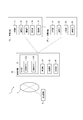
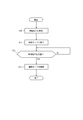
- FIG. 6 It is a figure showing a schematic structure of a management system concerning a 1st embodiment of this indication. It is a figure which shows schematic structure of the control apparatus shown in FIG. It is a functional block diagram of the management system shown in FIG. It is a flowchart which shows operation
- movement of the management system shown in FIG. 6 is a flowchart illustrating an operation of a power receiving device according to a second embodiment of the present disclosure.
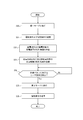
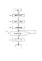
- 6 is a flowchart illustrating an operation of a power transmission device according to a second embodiment of the present disclosure. 6 is a flowchart illustrating an operation of a control device according to a second embodiment of the present disclosure. It is a sequence diagram showing operation of a management system concerning a 2nd embodiment of this indication. It is a functional block diagram of a management system concerning a modification of this indication.
- This disclosure is intended to provide an improved management system, control apparatus, and management system control method.
- an improved management system, control apparatus, and management system control method can be provided.
- FIG. 1 is a diagram illustrating a schematic configuration of a management system 1 according to the first embodiment of the present disclosure.
- the management system 1 is installed in a predetermined area.
- the management system 1 manages the safety of a predetermined area.
- the predetermined area is the house 2.
- the “predetermined area” in the present disclosure is not limited to the house 2.
- the “predetermined area” of the present disclosure may include a building over a plurality of floors, a planar area, a room in the building, and the like.
- the house 2 may be a detached house or an apartment house.
- the house 2 shown in FIG. 1 has one door 3 and one window 4.
- the number of doors 3 and the number of windows 4 that the house 2 has are not limited to one.
- the house 2 may have two or more doors 3 and two or more windows 4.
- the door 3 is installed at the entrance.
- the window 4 is provided on the outer wall of the house 2.
- the window 4 separates the inside of the house 2 from the outside.
- the resident goes out of the house 2 by passing through the entrance where the door 3 is installed.
- the resident who has gone out enters the house 2 by passing through the entrance where the door 3 is installed.
- “resident” in the present disclosure means a person who has the authority to live in the house 2. There may be one resident or a plurality of residents.
- the management system 1 includes power reception devices 10A, 10B, 10C, 10D, 10E, 10F, and 10G, a power transmission device 20, and a control device 30.
- the power transmission device 20 and the control device 30 are configured as separate devices. However, the power transmission device 20 and the control device 30 may be configured as one device.
- the power receiving devices 10A to 10G are not particularly distinguished, they are referred to as “power receiving device 10”.
- the management system 1 shown in FIG. 1 includes seven power receiving apparatuses 10. However, the number of power receiving devices 10 included in the management system 1 is not limited to seven.
- the management system 1 may include at least one power receiving device 10.
- the power receiving device 10 is disposed in the house 2.
- the power receiving device 10 receives wireless power from the power transmitting device 20.
- the power receiving device 10 can exhibit a desired function of the power receiving device 10 by the received wireless power. Further, the power receiving device 10 transmits a wireless signal requesting power transmission in order to cause the power transmitting device 20 to transmit wireless power to the power receiving device 10.
- the power receiving device 10 may be any device as long as it is configured to receive wireless power.
- the power receiving device 10 may be a security device.
- the power receiving device 10 that is a crime prevention device include a power receiving device 10A that is a monitoring camera described later, a power receiving device 10B that is a human sensor described later, and a power receiving device 10C that is an opening / closing sensor described later.
- the power receiving device 10 that is a security device is not limited to these.
- the power receiving device 10 that is a security device may include the power receiving device 10 that is a recording device.
- the power receiving device 10, which is a security device shifts to the operation mode based on the control of the control device 30.
- the “operation mode” means a state in which the apparatus can perform a desired function.
- the power receiving device 10 may be a disaster prevention device.
- the power receiving device 10 that is a disaster prevention device include a power receiving device 10D that is a fire alarm described later and a power receiving device 10E that is a gas detector described later.
- the power receiving device 10 which is a disaster prevention device is not limited to these.
- the power reception device 10 that is a disaster prevention device may include the power reception device 10 that is a water leakage sensor that detects water leakage in the house 2 and the power reception device 10 that is an earthquake sensor that detects an earthquake.
- the power receiving device 10, which is a disaster prevention device may shift to the operation mode based on the control of the control device 30.
- the power receiving device 10 may be a daily equipment. Living equipment is equipment used by residents in their daily lives. Examples of the power receiving device 10 that is a household device include a power receiving device 10F that is a temperature sensor described later, and a power receiving device 10G that is an illuminance sensor described later. However, the power receiving device 10 which is a daily life device is not limited to this.
- the power receiving device 10 that is a daily life device may include a wireless speaker, a cordless telephone, an electric shaver, an electric toothbrush, an electric vehicle, and the like.
- the power receiving device 10A is a surveillance camera.
- the power receiving device 10A may be capable of capturing a still image or capable of capturing a moving image.
- the power receiving device 10 ⁇ / b> A shifts to the operation mode based on the control of the control device 30.
- the power receiving device 10A captures an image of the inside of the house 2 when in the operation mode.
- the power receiving device 10B is a human sensor.
- the power receiving device 10B may include an infrared sensor or the like.
- the power receiving device 10B shifts to the operation mode based on the control of the control device 30.
- the power receiving device 10B can detect the location of a person in the house 2 when in the operation mode.
- the power receiving device 10C is an open / close sensor.
- the power receiving device 10 ⁇ / b> C is installed in the window 4.
- the power receiving device 10 ⁇ / b> C detects opening / closing of the window 4.
- the power receiving device 10 ⁇ / b> C shifts to the operation mode based on the control of the control device 30.
- the power receiving device 10C can detect opening and closing of the window 4 when in the operation mode.
- the power receiving device 10D is a fire alarm.
- the power receiving device 10 ⁇ / b> D detects the fire generated in the house 2 by detecting heat or smoke generated by the fire.
- the power receiving apparatus 10 ⁇ / b> D detects a fire that has occurred in the house 2
- the power receiving apparatus 10 ⁇ / b> D notifies, for example, by outputting sound.
- the power receiving device 10 ⁇ / b> D shifts to the operation mode based on the control of the control device 30.
- the power receiving device 10D can detect a fire that has occurred in the house 2 when in the operation mode.
- the power receiving device 10E is a gas detector.
- the power receiving device 10E detects a predetermined gas generated, for example, due to leakage or incomplete combustion.
- the predetermined gas may include a combustible gas and a toxic gas.
- the power receiving device 10E shifts to the operation mode based on the control of the control device 30.
- the power receiving device 10E can detect a predetermined gas in the house 2 when in the operation mode.
- the power receiving device 10F is a temperature sensor.
- the power receiving device 10F detects the ambient temperature.
- the power receiving device 10F shifts to the operation mode based on an operation by a resident or the like.
- the power receiving device 10F detects the temperature in the house 2 when in the operation mode.
- the power receiving device 10F displays the detected temperature on a display or the like included in the power receiving device 10F.
- the power receiving device 10G is an illuminance sensor.
- the power receiving device 10G detects ambient illuminance.
- the power receiving device 10G shifts to the operation mode based on an operation by a resident or the like.
- the power receiving device 10G detects the illuminance in the house 2 when in the operation mode.
- the power receiving device 10 ⁇ / b> G transmits the detected temperature to the luminaire installed in the house 2.
- the power transmission device 20 is disposed in the house 2.
- the power transmission device 20 can receive a signal requesting power transmission from the power receiving device 10.
- the power transmission device 20 transmits wireless power in the arrival direction of the wireless signal.
- the wireless power reaches the power receiving device 10 by going back the path through which the wireless signal has passed from the power receiving device 10 to the power transmitting device 20.
- the control device 30 is disposed in the house 2.
- the control device 30 may be installed in the vicinity of the door 3.
- FIG. 2 shows a schematic configuration of the control device 30 shown in FIG. As shown in FIG. 2, the control device 30 may be disposed on the left side toward the door 3.
- the control device 30 has a first mode for managing the safety of the house 2 and a second mode for releasing the management of the house 2. For example, when detecting a user operation on the management button 31A illustrated in FIG. 2, the control device 30 shifts to the first mode.
- the control device 30 shifts the operation mode of the power receiving devices 10A to 10C, which are security devices, to the operation mode.
- the control device 30 monitors the intrusion of a suspicious person in the house 2 by shifting the operation mode of the power receiving devices 10A to 10C, which are security devices, to the operation mode.
- the control device 30 shifts the operation mode of the power receiving devices 10D and 10E that are disaster prevention devices to the operation mode.
- the control device 30 monitors a disaster in the house 2 by shifting the operation mode of the power receiving devices 10D and 10E, which are disaster prevention devices, to the operation mode.
- the control device 30 causes the power transmission device 20 to transmit wireless power to the predetermined power reception device 10 among the power reception devices 10 arranged in the house 2 when in the first mode.
- the predetermined power receiving devices 10 are power receiving devices 10A to 10C that are crime prevention devices and power receiving devices 10D and 10E that are disaster prevention devices.
- the power receiving devices 10A to 10C that are crime prevention devices and the power receiving devices 10D and 10E that are disaster prevention devices are in the operation mode when the control device 30 is in the first mode.
- the control device 30 when the control device 30 is in the first mode, the power consumption of the power receiving devices 10A to 10C that are crime prevention devices and the power consumption of the power receiving devices 10D and 10E that are disaster prevention devices are the same as those in the second mode. It ’s bigger than it is.
- the power reception devices 10A to 10C that are crime prevention devices and the power reception device 10D that is a disaster prevention device. , 10E can be operated efficiently.
- the wireless power to the power receiving device 10 other than the predetermined power receiving device 10 among the power receiving devices 10 arranged in the house 2 is set to the power transmitting device 20. You may stop the power transmission.
- the power receiving devices 10 excluding the predetermined power receiving device 10 may be power receiving devices 10F and 10G that are daily life devices. In many cases, the power receiving devices 10F and 10G, which are household devices, are not used by residents when the control device 30 is in the first mode. For this reason, the power receiving devices 10F and 10G, which are household devices, often do not consume power when the control device 30 is in the first mode.
- the control device 30 when the control device 30 is in the first mode, the power receiving device as the predetermined power receiving device 10 from the power transmitting device 20 is stopped by stopping the transmission of the wireless power to the power receiving devices 10F and 10G that are living devices. Transmission of wireless power to 10A to 10E can be stabilized.
- FIG. 3 is a functional block diagram of the management system 1 shown in FIG.
- the management system 1 includes a power receiving device 10, a power transmission device 20, and a control device 30.
- the power receiving device 10, the power transmitting device 20, and the control device 30 can wirelessly communicate with each other.
- the power transmission device 20 and the control device 30 can wirelessly communicate with each other.
- the control device 30 and the communication device 6 can perform wireless communication with each other via the network 5.
- the wireless communication standard between the power receiving device 10 and the power transmitting device 20 and the control device 30 may be a short-range wireless communication standard.
- the wireless communication standard between the power transmission device 20 and the control device 30 may be a short-range wireless communication standard.
- the short-range wireless communication standards include, for example, wireless LAN, Bluetooth (registered trademark), IrDA (Infrared Data Association), NFC (Near Field Communication), and the like.
- the wireless communication standard between the control device 30 and the communication device 6 may be a long-distance wireless communication standard.
- the network 5 is, for example, the Internet. However, the network 5 is not limited to the Internet. The network 5 may be an appropriately configured network.
- the communication device 6 may be a communication device possessed or owned by a resident of the house 2 shown in FIG.
- the communication device 6 may be a communication device possessed or owned by the manager of the house 2 shown in FIG.
- the communication device 6 may be, for example, a communication device owned by a security company with which a resident has a contract.
- a resident or the like operates the communication device 6 to obtain identification information of the power receiving device 10 that performs wireless power feeding by the power transmitting device 20 when the control device 30 is in the first mode via the network 5. 30 may be transmitted.
- the power receiving device 10 that performs wireless power feeding by the power transmitting device 20 when the control device 30 is in the first mode is also referred to as “power receiving target power receiving device 10”.
- the power receiving device 10 to be fed may include the power receiving devices 10A to 10C shown in FIG. 1 which are crime prevention devices and the power receiving devices 10D and 10E shown in FIG. 1 which are disaster prevention devices.
- the resident or the like operates the communication device 6 to control the identification information of the power receiving device 10 that stops the power supply of the wireless power from the power transmitting device 20 when the control device 30 is in the first mode via the network 5. You may transmit to the apparatus 30.
- the power receiving device 10 that stops the feeding of the wireless power from the power transmitting device 20 when the control device 30 is in the first mode is also referred to as “a power receiving device 10 that is a non-power feeding target”.
- the power receiving device 10 that is a non-power supply target may include the power receiving devices 10F and 10G illustrated in FIG.
- the power receiving device 10 includes a power receiving unit 11, a communication unit 12, a power storage unit 13, a storage unit 14, and a control unit 15.
- the components included in the power receiving device 10 are not limited to these.
- the power receiving device 10 may include a component that exhibits a desired function of the power receiving device 10.
- the power receiving device 10 when the power receiving device 10 is a fire alarm, the power receiving device 10 may further include a sensor that detects heat or smoke generated by the fire and a buzzer that outputs sound.
- the power reception unit 11 receives wireless power from the power transmission device 20 based on the control of the control unit 15.
- the power reception unit 11 may include an antenna and a rectifier circuit.
- the antenna receives electromagnetic waves from the power transmission device 20.
- the rectifier circuit converts the electromagnetic wave received by the antenna into DC power.
- the communication unit 12 wirelessly communicates with the power transmission device 20 and the control device 30 based on the control of the control unit 15.
- the communication unit 12 may include a wireless communication module corresponding to the short-range wireless communication standard.
- the power storage unit 13 may include a secondary battery.
- the secondary battery is electrically connected to the power receiving unit 11.
- the secondary battery can store the power received by the power receiving unit 11.
- the power storage unit 13 supplies the stored power to each component of the power receiving device 10.
- the power storage unit 13 may include a primary battery in addition to the secondary battery.
- the storage unit 14 may be composed of a semiconductor memory or a magnetic memory.
- the storage unit 14 stores various information, a program for operating the power receiving device 10, and the like.
- the storage unit 14 may function as a work memory.
- the storage unit 14 may store identification information of the power receiving device 10.
- the control unit 15 is a processor that controls and manages the entire power receiving apparatus 10 including each functional block of the power receiving apparatus 10.
- the control unit 15 may be configured by a processor such as a CPU (Central Processing Unit) that executes a program that defines a control procedure, or a dedicated processor specialized for processing each function.
- a processor such as a CPU (Central Processing Unit) that executes a program that defines a control procedure, or a dedicated processor specialized for processing each function.
- the control unit 15 transmits a wireless signal requesting power transmission by the communication unit 12.
- the wireless signal may include identification information of the power receiving device 10.
- the radio signal may be a pilot signal or a beacon signal.
- the control unit 15 can receive a driving instruction from the control device 30 through the communication unit 12 when the power receiving device 10 is a security device or a disaster prevention device.
- the operation instruction is an instruction to shift the operation mode of the power receiving device 10 to the operation mode.
- the driving instruction is transmitted from the control device 30 to the power receiving device 10 when the control device 30 shifts to the first mode.
- the control unit 15 shifts the operation mode of the power receiving device 10 to the operation mode in accordance with the received operation instruction. For example, in the power receiving device 10A that is the monitoring camera illustrated in FIG. 1, the control unit 15 shifts to the operation mode and images the inside of the house 2 illustrated in FIG. 1.
- the control unit 15 may transmit information acquired when in the operation mode to the control device 30 by the communication unit 12. For example, in the power receiving device 10 ⁇ / b> A that is the monitoring camera illustrated in FIG. 1, the control unit 15 may transmit the captured data to the control device 30 through the communication unit 12.
- the control unit 15 can receive a setting instruction from the control device 30 together with the above-described driving instruction by the communication unit 12.
- the setting instruction is an instruction for causing the power receiving apparatus 10 to set the function of the power receiving apparatus 10 to a predetermined state.
- the setting instruction is an instruction to set the photographing angle of the monitoring camera so that the image of the monitoring camera includes the door 3 shown in FIG. May be included. Further, when the power receiving device 10A illustrated in FIG.
- the setting instruction may include an instruction for setting a shooting frequency at which the monitoring camera captures a still image to a predetermined frequency.
- the control unit 15 sets the function of the power receiving device 10 to a predetermined state in accordance with the received setting instruction.
- the control unit 15 may store the setting of the function before the change of the power receiving device 10 in the storage unit 14.
- the control unit 15 can receive a release instruction from the control device 30 by the communication unit 12 after receiving the power supply instruction and the driving instruction.
- the cancellation instruction is an instruction to cancel the power supply instruction and the operation instruction.
- the release instruction is transmitted from the control device 30 to the power receiving device 10 when the control device 30 shifts to the second mode.
- the control unit 15 releases the operation mode of the power receiving device 10.
- the control part 15 may stop transmission of the radio signal which requests
- control unit 15 acquires the setting of the function before the change of the power receiving device 10 from the storage unit 14. Good. Further, the control unit 15 may return the function setting of the power receiving device 10 to the function setting before change acquired from the storage unit 14.
- the power transmission device 20 includes a power transmission unit 21, a communication unit 22, a storage unit 23, and a control unit 24.
- the component which the power transmission apparatus 20 has is not limited to these.
- the power transmission device 20 may further include a power storage unit that supplies power to each component of the power transmission device 20.
- the power transmission unit 21 transmits wireless power to the power receiving device 10 based on the control of the control unit 24.
- the power transmission unit 21 may include an antenna and an oscillator.
- the oscillator generates AC power having a predetermined frequency based on, for example, power supplied to the power transmission device 20 from a power source such as a power distribution facility.
- the antenna radiates AC power of a predetermined frequency generated by the oscillator as an electromagnetic wave.
- the communication unit 22 wirelessly communicates with the power receiving device 10 and the control device 30 based on the control of the control unit 24.
- the communication unit 12 may include a wireless communication module corresponding to the short-range wireless communication standard.
- the storage unit 23 may be composed of a semiconductor memory or a magnetic memory.
- the storage unit 23 stores various information, a program for operating the power transmission device 20, and the like.
- the storage unit 23 may function as a work memory.
- the control unit 24 is a processor that controls and manages the entire power transmission device 20 including each functional block of the power transmission device 20.
- the control unit 24 may be configured by a processor such as a CPU (Central Processing Unit) that executes a program that defines a control procedure, or a dedicated processor specialized for processing of each function.
- a processor such as a CPU (Central Processing Unit) that executes a program that defines a control procedure, or a dedicated processor specialized for processing of each function.
- CPU Central Processing Unit
- the control unit 24 can receive a radio signal requesting power transmission from the power receiving device 10 through the communication unit 22. When the control unit 24 receives a wireless signal requesting power transmission, the control unit 24 transmits wireless power in the arrival direction of the wireless signal by the power transmission unit 21.
- the control unit 24 can receive the power supply instruction and the identification information of the power receiving device 10 to be supplied from the control device 30 by the communication unit 22.
- the control unit 24 uses, as the identification information of the power receiving device 10 to be supplied with power, the identification information of the power receiving devices 10A to 10C shown in FIG. 1 that is a security device and the power receiving devices 10D and 10E shown in FIG. Identification information may be received.
- the power supply instruction is an instruction for causing the power transmission apparatus 20 to transmit wireless power to the power receiving apparatus 10 to be supplied with power.
- the power supply instruction is transmitted from the control device 30 to the power transmission device 20 when the control device 30 shifts to the first mode.
- the control unit 24 When receiving the power supply instruction, the control unit 24 transmits wireless power to the power receiving device 10 specified by the identification information received together with the power supply instruction. For example, it is assumed that the control unit 24 receives a wireless signal requesting power transmission from the power receiving device 10 by the communication unit 22. In this case, when the identification information included in the wireless signal is included in the identification information of the power receiving device 10 that is the power supply target received from the control device 30, the control unit 24 transmits wireless power to the power receiving device 10. .
- control unit 24 can receive the power supply stop instruction and the identification information of the power receiving device 10 that is the non-power supply target from the control device 30 by the communication unit 22.
- the control unit 24 can receive the identification information of the power receiving devices 10F and 10G shown in FIG.
- the power supply stop instruction is an instruction to cause the power transmission apparatus 20 to stop the transmission of wireless power to the power reception apparatus 10 that is the non-power supply target.
- the power supply stop instruction is transmitted from the control apparatus 30 to the power transmission apparatus 20 when the control apparatus 30 shifts to the first mode, similarly to the above-described power supply instruction.
- the control unit 24 stops the transmission of wireless power to the power receiving device 10 specified by the received identification information together with the power supply stop instruction.
- control unit 24 receives a wireless signal requesting power transmission from the power receiving device 10 by the communication unit 22.
- the control unit 24 transmits wireless power to the power receiving device 10. To stop.
- the control unit 24 can receive a release instruction from the control device 30 by the communication unit 22 after receiving the power supply instruction and the power supply stop instruction.
- the release instruction is transmitted from the control device 30 to the power transmission device 20 when the control device 30 shifts to the second mode.
- the control unit 24 may stop the transmission of the wireless power to the power receiving device 10 that is transmitting the wireless power according to the power supply instruction.
- the control unit 24 may stop the transmission of wireless power to the power receiving devices 10A to 10C shown in FIG. 1 that are crime prevention devices and the power receiving devices 10D and 10E shown in FIG. 1 that are disaster prevention devices. .
- control unit 24 may resume the transmission of the wireless power to the power receiving apparatus 10 that has stopped the transmission of the wireless power in accordance with the instruction to stop the power supply. For example, the control unit 24 may resume the transmission of wireless power to the power receiving apparatuses 10F and 10G illustrated in FIG.
- the control device 30 includes an input unit 31, a communication unit 32, a storage unit 33, and a control unit 34.
- the component which the control apparatus 30 has is not limited to these.
- the control device 30 may further include a sound output unit.
- the input unit 31 accepts user operation (resident operation).
- the input unit 31 may include a management button 31A and a release button 31B.
- the management button 31A may be disposed in front of the control device 30 as shown in FIG.
- the management button 31A is operated by the resident when the resident wants the management system 1 to manage the safety of the house 2.
- the management button 31A is operated by the resident when the resident wants the management system 1 to manage the safety of the house 2.
- the resident wants the management system 1 to manage the safety of the house 2, for example, when the resident goes out of the house 2 or when the resident goes to bed.
- the release button 31B may be disposed in front of the control device 30 as shown in FIG.
- the release button 31 ⁇ / b> B is operated by the resident when the resident wants to release the management of the safety of the house 2 by the management system 1.
- the release button 31 ⁇ / b> B is operated by the resident when the resident wants to release the management of the safety of the house 2 by the management system 1.
- the resident wants to cancel the safety management of the house 2 by the management system 1, for example, when the resident who has gone out returns to the house 2, and when the resident who has gone to bed gets up.
- the communication unit 32 wirelessly communicates with the power receiving device 10 and the power transmission device 20 based on the control of the control unit 34.
- the communication unit 32 performs long-distance wireless communication with the communication device 6 via the network 5 based on the control of the control unit 34.
- the communication unit 32 may include a wireless communication module corresponding to the short-range wireless communication standard and a wireless communication module corresponding to the long-range wireless communication standard.
- the communication unit 32 may include a wireless communication module corresponding to the non-contact communication standard.
- the non-contact communication standard may be an NFC (Near Field Communication) standard.
- NFC Near Field Communication
- a part of the communication unit 32 may be disposed in front of the control device 30 as shown in FIG.
- the storage unit 33 may be composed of a semiconductor memory or a magnetic memory.
- the storage unit 33 stores various information and a program for operating the control device 30.
- the storage unit 33 may function as a work memory.
- the storage unit 33 stores, for example, the identification information of the power receiving device 10 that is the power supply target acquired from the communication device 6.
- the storage unit 33 uses, as the identification information of the power receiving device 10 to be supplied with power, the identification information of the power receiving devices 10A to 10C shown in FIG. 1 which is a security device and the power receiving devices 10D and 10E shown in FIG. The identification information is stored.
- the storage unit 33 stores, for example, the identification information of the power receiving device 10 that is a non-power supply target acquired from the communication device 6.
- the storage unit 33 stores the identification information of the power receiving devices 10F and 10G illustrated in FIG.
- the control unit 34 is a processor that controls and manages the entire control device 30 including each functional block of the control device 30.
- the control unit 34 may be configured by a processor such as a CPU (Central Processing Unit) that executes a program defining a control procedure, or a dedicated processor specialized for processing each function.
- a processor such as a CPU (Central Processing Unit) that executes a program defining a control procedure, or a dedicated processor specialized for processing each function.
- CPU Central Processing Unit
- the control unit 34 When the control unit 34 detects a user operation on the management button 31A, the control unit 34 shifts the operation mode of the control device 30 to the first mode.
- the control unit 34 shifts the operation mode of the control device 30 to the first mode when the communication unit 32 detects an electromagnetic wave from the non-contact card. It's okay.
- the control unit 34 may shift the operation mode of the control device 30 to the first mode at the first time.
- the first time may be set in advance. The first time may be, for example, the time when the resident of the house 2 shown in FIG. 1 goes to bed, the time when the resident leaves the house 2 for commuting, or the like.
- the control unit 34 When the control unit 34 shifts the operation mode of the control device 30 to the first mode, the control unit 34 gives driving instructions to the power receiving devices 10A to 10E shown in FIG. 1 which is a crime prevention device and the power receiving device shown in FIG. 1 which is a disaster prevention device. 10D and 10E are transmitted by the communication unit 32. When the setting instruction is stored in the storage unit 33, the control unit 34 may transmit the setting instruction together with the driving instruction.
- the control unit 34 shifts the operation mode of the control device 30 to the first mode, acquires the identification information of the power receiving target device 10 from the storage unit 33.
- the control unit 34 shows from the storage unit 33, as the identification information of the power receiving device 10 to be fed, the identification information of the power receiving devices 10A to 10C shown in FIG.
- the identification information of the power receiving apparatuses 10D and 10E is acquired.
- the control unit 34 transmits the power supply instruction and the identification information of the power receiving device 10 to be supplied to the power transmission device 20 through the communication unit 32.
- the control unit 34 shifts the operation mode of the control device 30 to the first mode, acquires the identification information of the power receiving device 10 that is the non-power supply target from the storage unit 33. For example, the control unit 34 acquires, from the storage unit 33, identification information of the power receiving devices 10F and 10G illustrated in FIG. The control unit 34 transmits the power supply stop instruction and the identification information of the power receiving device 10 to be unpowered to the power transmission device 20 by the communication unit 32.
- the control unit 34 When the control unit 34 detects a user operation on the release button 31B, the control unit 34 shifts the operation mode of the control device 30 to the second mode.
- the control unit 34 causes the operation mode of the control device 30 to shift to the second mode when the communication unit 32 detects an electromagnetic wave from the non-contact card. It's okay.
- the control unit 34 may shift the operation mode of the control device 30 to the second mode at the second time.
- the second time may be set in advance. The second time may be, for example, the time when the resident of the house 2 shown in FIG. 1 gets up, the time when the resident who has gone out for commuting or the like returns to the house 2, and the like.
- control unit 34 When the control unit 34 shifts the operation mode of the control device 30 to the second mode, the control unit 34 transmits a release instruction to the power receiving device 10 and the power transmission device 20 by the communication unit 32.
- FIG. 4 is a flowchart showing the operation of the power receiving device 10 shown in FIG.
- the control unit 15 executes the process illustrated in FIG.
- the control unit 15 receives a driving instruction from the control device 30 through the communication unit 12 (step S10).
- the control unit 15 can receive a driving instruction by the process of step S10.
- the control unit 15 may further receive a setting instruction from the control device 30 by the communication unit 12.
- the control unit 15 shifts the operation mode of the power receiving apparatus 10 to the operation mode (step S11).
- step S11 when receiving the setting instruction in the process of step S10, the control unit 15 sets the function of the power receiving device 10 to a predetermined state according to the setting instruction.
- the control unit 15 may store the setting of the function before the change of the power receiving device 10 in the storage unit 14.
- the control unit 15 determines whether or not a release instruction has been received from the control device 30 by the communication unit 12 (step S12). When it determines with the control part 15 having received the cancellation
- control unit 15 cancels the operation mode of the power receiving device 10.
- the control unit 15 may acquire the function setting before the change of the power receiving device 10 from the storage unit 14. Furthermore, the control unit 15 may return the function setting of the power receiving device 10 to the function setting before change acquired from the storage unit 14.
- FIG. 5 is a flowchart showing the operation of the power transmission device 20 shown in FIG. For example, when the power of the power transmission device 20 is turned on, the control unit 24 starts the process illustrated in FIG.
- the control unit 24 receives the power supply instruction and the identification information of the power receiving device 10 to be supplied from the control device 30 by the communication unit 22 (step S20).
- the control unit 24 transmits wireless power to the power receiving device 10 specified by the identification information received together with the power supply instruction (step S21).
- the control unit 24 receives from the control device 30 by the communication unit 22 an instruction to stop power supply and the identification information of the power receiving device 10 that is the non-power supply target (step S22).
- the control unit 24 stops the transmission of wireless power to the power receiving device 10 specified by the identification information received together with the power supply stop instruction (step S23).
- the control unit 24 determines whether or not a release instruction is received from the control device 30 by the communication unit 22 (step S24).
- control unit 24 determines that the release instruction has been received (step S24: Yes)
- the process ends.
- the control unit 24 may stop the transmission of wireless power by the process of step S21.
- the control unit 24 may resume the transmission of the wireless power to the power receiving device 10 that stopped the transmission of the wireless power in the process of step S23.
- step S24 when determining that the release instruction is not received (step S24: No), the control unit 24 executes the process of step S24 again.
- FIG. 6 is a flowchart showing the operation of the control device 30 shown in FIG.
- the control unit 34 starts the process shown in FIG.
- the control part 34 may start the process shown in FIG. Further, the control unit 34 may start the processing illustrated in FIG. 6 at the first time.
- the control unit 34 shifts the operation mode of the control device 30 to the first mode (step S30).
- the control unit 34 transmits a driving instruction by the communication unit 32 to the power receiving devices 10A to 10C shown in FIG. 1 which are crime prevention devices and the power receiving devices 10D and 10E shown in FIG. 1 which are disaster prevention devices (step S31).
- the control unit 34 may transmit the setting instruction together with the driving instruction.
- the control unit 34 acquires the identification information of the power receiving device 10 to be supplied from the storage unit 33.
- the control unit 34 transmits the power supply instruction and the identification information of the power receiving device 10 to be supplied to the power transmission device 20 through the communication unit 32 (step S32).
- the control unit 34 acquires the identification information of the power receiving device 10 that is the non-power supply target from the storage unit 33.
- the control unit 34 transmits an instruction to stop power feeding and the identification information of the power receiving device 10 to be unpowered to the power transmission device 20 by the communication unit 32 (step S33).
- the control unit 34 determines whether a user operation on the release button 31B has been detected (step S34). When it determines with the control part 34 having detected the user operation with respect to the cancellation
- step S35 the control unit 34 shifts the operation mode of the control device 30 to the second mode.
- step S ⁇ b> 36 the control unit 34 transmits a release instruction to the power receiving device 10 and the power transmission device 20 by the communication unit 32.
- control part 34 may determine whether the electromagnetic wave from the non-contact type card
- FIG. 7 is a sequence diagram showing an operation of the management system 1 shown in FIG.
- the management system 1 starts the process illustrated in FIG.
- the communication unit 32 of the control device 30 is compatible with the non-contact communication standard
- the management system 1 shows that when the control device 30 detects electromagnetic waves from the non-contact type card by the communication unit 32, FIG. The processing shown may be performed.
- the management system 1 may start the process shown in FIG. 7 at the first time.
- control unit 34 shifts the operation mode of the control device 30 to the first mode (step S40).
- control unit 34 transmits a driving instruction to the power receiving devices 10A to 10C that are crime prevention devices and the power receiving devices 10D and 10E that are disaster prevention devices by the communication unit 32 (step S41).
- control unit 34 may transmit a setting instruction together with the driving instruction to the power receiving apparatuses 10A to 10E through the communication unit 32.
- control unit 15 shifts the operation mode of the power receiving devices 10A to 10E to the operation mode (step S42).
- control unit 34 transmits the power supply instruction and the identification information of the power receiving devices 10A to 10E as the identification information of the power receiving device 10 to be supplied to the power transmission device 20 by the communication unit 32 (step S43A).
- control unit 34 transmits the power supply stop instruction and the identification information of the power receiving devices 10 ⁇ / b> F and 10 ⁇ / b> G to the power transmission device 20 by the communication unit 32 as the identification information of the power reception device 10 that is the non-power supply target (step S ⁇ b> 3 S43B).
- the control unit 15 transmits a radio signal requesting power transmission by the communication unit 12 (step S44A).
- the control unit 24 receives wireless signals from the power reception devices 10A to 10E through the communication unit 22.
- the control unit 24 transmits wireless power in the arrival direction of the wireless signal by the power transmission unit 21 (step S44B).
- the control unit 15 transmits a radio signal requesting power transmission by the communication unit 12 (step S44C).
- the control unit 24 receives a wireless signal requesting power transmission from the power reception devices 10 ⁇ / b> F and 10 ⁇ / b> G through the communication unit 22.
- the identification information of the power reception devices 10F and 10G included in the wireless signal received by the power transmission device 20 is included in the identification information of the power reception device 10 that is the non-power supply target received by the power transmission device 20 from the control device 30 in the process of step S43B. Therefore, the control unit 24 does not execute wireless power transmission to the power receiving apparatuses 10F and 10G.
- control unit 34 detects a user operation on the release button 31B (step S45). In the control device 30, the control unit 34 shifts the operation mode of the control device 30 to the second mode (step S46).
- control unit 34 transmits a release instruction to the power transmission device 20 by the communication unit 12 (step S47A). In the control device 30, the control unit 34 transmits a release instruction to the power receiving devices 10A to 10E through the communication unit 12 (step S47B).
- control unit 15 cancels the operation mode of the power receiving device 10 (step S48).
- the control device 30 when the control device 30 shifts to the first mode, the control device 30 transmits a power feeding instruction and identification information of the power receiving device 10 to be fed to the power transmitting device 20.
- the control device 30 causes the power transmission device 20 to transmit wireless power to the power reception device 10 that is the power supply target as the predetermined power reception device 10 when in the first mode.
- wireless power transmission / reception between the power transmission device 20 and the power reception device 10 can be controlled by the control device 30 that manages the safety of the house 2 illustrated in FIG. . That is, in the management system 1 according to the present embodiment, transmission / reception of wireless power between the power transmission device 20 and the power reception device 10 is controlled by using the control device 30 that manages the safety of the house 2 illustrated in FIG. be able to. With such control, in the management system 1 according to the present embodiment, it is not necessary to separately provide a device that controls transmission / reception of wireless power between the power transmission device 20 and the power reception device 10. Therefore, in the management system 1 according to the present embodiment, it is possible to prevent an increase in cost by separately providing a device that controls transmission and reception of wireless power between the power transmission device 20 and the power reception device 10.
- the power receiving devices 10A to 10C shown in FIG. 1 that are crime prevention devices and the power receiving devices 10D and 10E shown in FIG. 1 that are disaster prevention devices are in the operation mode when the control device 30 is in the first mode. Therefore, when the control device 30 is in the first mode, the power consumption of the power receiving devices 10A to 10C that are crime prevention devices and the power consumption of the power receiving devices 10D and 10E that are disaster prevention devices are the same as those in the second mode. It ’s bigger than it is.
- wireless power is transmitted to the power receiving devices 10A to 10C that are crime prevention devices and the power receiving devices 10D and 10E that are disaster prevention devices. With this control, in this embodiment, the power receiving devices 10A to 10C that are crime prevention devices and the power receiving devices 10D and 10E that are disaster prevention devices can be efficiently operated.
- the control device 30 when the control device 30 shifts to the first mode, the control device 30 transmits to the power transmission device 20 an instruction to stop power feeding and identification information of the power receiving device 10 that is not to be fed.
- the power receiving device 10F, 10G which is a living device as the power receiving device 10 excluding the predetermined power receiving device 10
- Wireless power to can be stopped.
- the management system 1 according to the second embodiment can adopt the same configuration as the management system 1 according to the first embodiment. Therefore, the following description will focus on differences from the first embodiment with reference to FIGS. 1 to 3.
- control unit 34 gives priority to receiving power supplied from the power transmission device 20 to the power reception device 10 included in the management system 1 when the control device 30 is in the first mode. Set.
- control unit 34 may set higher priority levels for the power receiving devices 10A to 10C shown in FIG. 1 that are crime prevention devices and the power receiving devices 10D and 10E that are disaster prevention devices. Moreover, the control part 34 may set the priority of the power receiving apparatus 10F and 10G which are living devices low.
- the control unit 34 may set the priority based on the remaining battery level of the power storage unit 13 of the power receiving device 10. In this case, the control unit 34 may set a high priority for the power receiving device 10 having the power storage unit 13 with a small remaining battery level. Further, the control unit 34 may set a low priority for the power receiving device 10 having the power storage unit 13 with a large remaining battery level. In this example, the control unit 15 of the power receiving device 10 may transmit the remaining battery level of the power storage unit 13 to the control device 30 through the communication unit 12.
- control part 34 may transmit the battery remaining amount of the primary battery of the electrical storage part 13 to the communication apparatus 6 by the communication part 32, when the electrical storage part 13 is comprised including a primary battery and a secondary battery.
- a resident or the like can grasp the remaining battery level of the primary battery of the power storage unit 13 of the power receiving device 10. For example, a resident who is out can know that the remaining battery level of the primary battery of the power storage unit 13 of the power receiving device 10 is low via the communication device 6. In this case, the resident who is going out can purchase a new primary battery on the go. Further, the resident can return to the house 2 and replace the primary battery of the power storage unit 13 of the power receiving device 10 with a new purchased primary battery.
- control unit 34 When the control unit 34 shifts the operation mode of the control device 30 to the first mode, the control unit 34 transmits the power supply instruction and the priority set for each power receiving device 10 to the power transmission device 20 by the communication unit 32. In addition, when the control unit 34 shifts the operation mode of the control device 30 to the second mode, the control unit 34 transmits a release instruction to the power transmission device 20 and the power reception device 10 by the communication unit 32.
- the control unit 24 receives the supply instruction and the priority set for each power receiving device 10 from the control device 30 by the communication unit 22. Based on the priority set for each power receiving device 10, the control unit 24 transmits wireless power to a predetermined power receiving device 10 among at least one power receiving device 10 included in the management system 1.
- control unit 24 may transmit wireless power to the power receiving device 10 in which a priority level exceeding a predetermined value is set.
- the control unit 24 may transmit equivalent wireless power to the power receiving device 10 for which a priority level exceeding a predetermined value is set.
- control unit 24 may transmit a larger amount of wireless power to the power receiving device 10 having a higher priority.
- control unit 24 may perform control so that the high priority set for the power receiving device 10 is proportional to the wireless power transmitted to the power receiving device.
- the control unit 24 may cancel the transmission of the wireless power based on the priority when receiving the cancellation instruction from the control device 30 by the communication unit 22.
- FIG. 8 is a flowchart illustrating an operation of the power receiving device 10 according to the second embodiment of the present disclosure. For example, when the power of the power receiving device 10 is turned on, the control unit 15 executes the process illustrated in FIG.
- the control unit 15 executes the processes of steps S50 and S51 in the same manner as the processes of steps S10 and S11 shown in FIG.
- the control unit 15 transmits the remaining battery level of the power storage unit 13 to the control device 30 through the communication unit 12 (step S52).
- the control unit 15 may further transmit the remaining battery level of the primary battery to the control device 30 by the communication unit 12. .
- the control unit 15 executes the processes of steps S53 and S54 in the same manner as the processes of steps S12 and S13 shown in FIG.
- control part 15 does not need to perform the process of step S52, when the control apparatus 30 does not set a priority based on the battery remaining charge of the electrical storage part 13.
- FIG. 9 is a flowchart illustrating an operation of the power transmission device 20 according to the second embodiment of the present disclosure. For example, when the power of the power transmission device 20 is turned on, the control unit 24 starts the process illustrated in FIG.
- the control unit 24 receives the power supply instruction and the priority set for each power receiving device 10 from the control device 30 by the communication unit 22 (step S60).
- the control unit 24 transmits wireless power to the power receiving device 10 by the power transmission unit 21 based on the priority of each power receiving device 10 received in the process of step S60 (step S61).
- the control part 24 performs the process of step S62 similarly to the process of step S24 shown in FIG. In the process of step S ⁇ b> 63, the control unit 24 cancels the transmission of wireless power based on the priority of each power receiving device 10.
- FIG. 10 is a flowchart illustrating an operation of the control device 30 according to the second embodiment of the present disclosure.
- the control unit 34 starts the processing illustrated in FIG.
- the control part 34 may start the process shown in FIG.
- the control unit 34 may start the process illustrated in FIG. 10 when the first time described in the first embodiment is reached.
- the control unit 34 executes the processes of steps S70 and S71 in the same manner as the processes of steps S30 and S31 shown in FIG.
- the control unit 34 receives the remaining battery level of the power storage unit 13 of the power receiving device 10 from the power receiving device 10 through the communication unit 32 (step S72).
- the control unit 34 receives the remaining battery level of the primary battery of the power storage unit 13 from the power receiving device 10 by the communication unit 32. You can do it. Further, the control unit 34 may transmit the remaining battery level of the primary battery of the power storage unit 13 to the communication device 6 through the communication unit 32.
- the control unit 34 sets priority for the power receiving apparatus 10 (step S73).
- the control unit 34 transmits the power supply instruction and the priority set in the process of step S73 to the power transmission device 20 by the communication unit 32 (step S74).
- the control unit 34 performs the processes of steps S75, S76, and S77 in the same manner as the processes of steps S34, S35, and S36 shown in FIG.
- control part 34 does not need to perform the process of step S72, when not setting a priority based on the battery remaining charge of the electrical storage part 13 of the power receiving apparatus 10 in the process of step S73.
- FIG. 11 is a sequence diagram illustrating an operation of the management system 1 according to the second embodiment of the present disclosure.
- the management system 1 starts the process illustrated in FIG.
- curd by the communication part 32 the management system 1 will be shown in FIG. The processing shown may be performed.
- the management system 1 may start the processing illustrated in FIG. 11 when the first time described in the first embodiment is reached.
- the control device 30 executes the processes of steps S80 and S81 in the same manner as the processes of steps S40 and S41 shown in FIG.
- the power receiving apparatuses 10A to 10E execute the process of step S82 in the same manner as the process of step S42 shown in FIG.
- control unit 15 transmits the remaining battery level of power storage unit 13 (step S83A).
- control unit 15 transmits the remaining battery level of power storage unit 13 (step S83B).
- the control unit 15 of the power receiving device 10 may further transmit the remaining battery level of the primary battery when the power storage unit 13 includes the primary battery and the secondary battery.
- the control unit 34 receives the remaining battery level of the power storage unit 13 from the power receiving device 10 through the communication unit 32.
- the control unit 34 may receive the remaining battery level of the primary battery of the power storage unit 13 from the power receiving device 10 through the communication unit 32. Further, the control unit 34 may transmit the remaining battery level of the primary battery of the power storage unit 13 to the communication device 6 through the communication unit 32.
- control unit 34 sets the priority of each power receiving device 10 (step S84A).
- the control unit 34 transmits the power supply instruction and the priority set in the process of step S84A to the power transmission device 20 by the communication unit 32 (step S84B).
- the power receiving apparatuses 10A to 10E execute the process of step S85A in the same manner as the process of step S44A shown in FIG.
- the power transmission device 20 performs the process of step S85B in the same manner as the process of step S44B illustrated in FIG.
- the power receiving apparatuses 10F and 10G execute the process of step S85C in the same manner as the process of step S44C illustrated in FIG.
- the control device 30 executes the processes of steps S86 and S87 in the same manner as the processes of steps S45 and S46 shown in FIG.
- the control device 30 executes the processes of steps S88A and S88B in the same manner as the processes of steps S47A and S47B shown in FIG.
- the power receiving apparatuses 10A to 10E execute the process of step S89 in the same manner as the process of step S48 shown in FIG.
- step S84A When the control unit 34 of the control device 30 does not set the priority based on the remaining battery level of the power storage unit 13 of the power receiving device 10 in the process of step S84A, the power receiving devices 10A to 10G each of steps S83A and S84B There is no need to execute processing.
- Such a management system 1 according to the second embodiment can achieve the same effects as the management system 1 according to the first embodiment.
- Other configurations of the management system 1 according to the second embodiment are the same as those of the management system 1 according to the first embodiment.
- the control device 30 gives a setting instruction together with the driving instruction to the power receiving devices 10A to 10C that are crime prevention devices and the power receiving devices 10D and 10E that are disaster prevention devices. Sent directly to. However, the control device 30 may transmit a setting instruction together with the driving instruction to the power receiving devices 10A to 10C that are crime prevention devices and the power receiving devices 10D and 10E that are disaster prevention devices via the power transmission device 20.
- the control device 30 when detecting a user operation on the management button 31A, the control device 30 shifts to the first mode and transmits a power supply instruction to the power transmission device 20.
- the timing at which the control device 30 transmits the power supply instruction is not limited to this.
- the control device 30 may transmit the power supply instruction to the power transmission device 20 in a time zone (for example, a night time zone) when the electricity rate is reduced.
- FIG. 12 illustrates a functional block diagram of the management system 101 according to a modification example of the present disclosure.
- the management system 101 according to the modification includes a control device 130 instead of the power transmission device 20 and the control device 30 illustrated in FIG. 3.
- the control device 130 includes the power transmission device 20 and the control device 30 illustrated in FIG. 3 as one device.
- the control device 130 includes a power transmission unit 21, an input unit 31, a communication unit 32, a storage unit 33, and a control unit 134.
- the control unit 134 can execute the same processing as that performed by the control unit 24 of the power transmission device 20 illustrated in FIG.
- the control unit 134 can receive a radio signal requesting power transmission from the power receiving device 10 by the communication unit 32.
- the control unit 134 can transmit the wireless power by the power transmission unit 21 in the arrival direction of the wireless signal.
- the control part 134 can perform the process similar to the control part 34 of the control apparatus 30 shown in FIG. For example, when the control device 130 is in the first mode, the control unit 134 can transmit wireless power to the predetermined power receiving device of the power receiving device 10 by the power transmitting unit 21.
- the control unit 15 of the power receiving device 10 in the first embodiment described above also includes the battery remaining in the power storage unit 13 as in the second embodiment.
- the amount may be transmitted to the control device 30 by the communication unit 12.
- the control unit 34 of the control device 30 may transmit the remaining battery level of the primary battery of the power storage unit 13 received from the power receiving device 10 to the communication device 6 through the communication unit 32.
- descriptions such as “first” and “second” are identifiers for distinguishing the configuration.
- the configurations distinguished by the description of “first” and “second” in the present disclosure can exchange numbers in the configurations.
- the first mode can exchange the identifiers “first” and “second” with the second mode.
- the identifier exchange is performed at the same time.
- the configuration is distinguished even after the identifier is exchanged.
- the identifier may be deleted.
- the configuration from which the identifier is deleted is distinguished by a code. Based on only the description of identifiers such as “first” and “second” in the present disclosure, it should not be used as an interpretation of the order of the configuration, or as a basis for the existence of identifiers with smaller numbers.
Landscapes
- Engineering & Computer Science (AREA)
- Power Engineering (AREA)
- Computer Networks & Wireless Communication (AREA)
- Alarm Systems (AREA)
- Remote Monitoring And Control Of Power-Distribution Networks (AREA)
- Charge And Discharge Circuits For Batteries Or The Like (AREA)
Abstract
管理システムは、送電を要求する無線信号を発信する少なくとも1つの受電装置と、無線信号の到来方向に、無線電力を送電する送電装置と、制御装置とを備える。制御装置は、所定領域を管理する第1モードと、当該所定領域の管理を解除する第2モードとを有する制御装置とを有する。制御装置は、第1モードであるとき、送電装置に、少なくとも1つの受電装置のうちの所定受電装置へ無線電力を送電させる。
Description
本出願は、2018年4月24日に日本国に特許出願された特願2018-083401の優先権を主張するものであり、この先の出願の開示全体を、ここに参照のために取り込む。
本開示は、管理システム、制御装置及び管理システムの制御方法に関する。
従来、電磁波によって電力を電子機器に供給する技術が知られている(例えば、特許文献1)。特許文献1には、マイクロ波によって電力をデバイスに供給する送電装置が開示されている。
一態様の管理システムは、送電を要求する無線信号を発信する少なくとも1つの受電装置と、前記無線信号の到来方向に、無線電力を送電する送電装置と、制御装置とを備える。前記制御装置は、所定領域を管理する第1モードと、当該所定領域の管理を解除する第2モードとを有する。前記制御装置は、前記第1モードであるとき、前記送電装置に、前記少なくとも1つの受電装置のうちの所定受電装置へ無線電力を送電させる。
一態様の管理システムは、送電を要求する無線信号を発信する少なくとも1つの受電装置と、前記無線信号の到来方向に、無線電力を送電する制御装置とを備える。前記制御装置は、所定領域を管理する第1モードと、当該所定領域の管理を解除する第2モードとを有する。前記制御装置は、前記第1モードであるとき、前記少なくとも1つの受電装置のうちの所定受電装置に無線電力を送電する。
一態様の制御装置は、所定領域を管理する第1モードと、当該所定領域の管理を解除する第2モードとを有する。前記制御装置は、送電を要求する無線信号を発信する少なくとも1つの受電装置と、前記無線信号の到来方向に、無線電力を送電する送電装置とを制御する制御部を有する。前記制御部は、前記第1モードであるとき、前記送電装置に、前記少なくとも1つの受電装置のうちの所定受電装置へ無線電力を送電させる。
一態様の管理システムの制御方法は、少なくとも1つの受電装置と、送電装置と、所定領域を管理する第1モード及び当該所定領域の管理を解除する第2モードを有する制御装置とを備える管理システムの制御方法である。当該管理システムの制御方法は、前記受電装置が、送電を要求する無線信号を発信するステップを含む。さらに、前記管理システムの制御方法は、前記送電装置が、前記無線信号の到来方向に、無線電力を送電するステップを含む。さらに、前記管理システムの制御方法は、前記制御装置が、前記第1モードであるとき、前記送電装置に、前記少なくとも1つの受電装置のうちの所定受電装置へ無線電力を送電させるステップを含む。
従来の電磁波によって電力を供給する技術には、改善の余地がある。
本開示は、改善された、管理システム、制御装置及び管理システムの制御方法を提供することを目的とする。
本開示によれば、改善された、管理システム、制御装置及び管理システムの制御方法が提供され得る。
以下、本発明に係る実施形態について、図面を参照して説明する。以下、各図において共通の構成部には、同一符号を付す。
(第1実施形態)
図1は、本開示の第1実施形態に係る管理システム1の概略構成を示す図である。管理システム1は、所定領域に設置される。管理システム1は、所定領域の安全を管理する。本実施形態では、所定領域は、住宅2である。ただし、本開示において「所定領域」は、住宅2に限定されない。本開示の「所定領域」は、複数階に渡る建物、平面的な領域及び建物内の一室等を含んでよい。
図1は、本開示の第1実施形態に係る管理システム1の概略構成を示す図である。管理システム1は、所定領域に設置される。管理システム1は、所定領域の安全を管理する。本実施形態では、所定領域は、住宅2である。ただし、本開示において「所定領域」は、住宅2に限定されない。本開示の「所定領域」は、複数階に渡る建物、平面的な領域及び建物内の一室等を含んでよい。
住宅2は、戸建住宅であってよいし、集合住宅であってよい。図1に示す住宅2は、1つのドア3及び1つの窓4を有する。ただし、住宅2が有するドア3の数及び窓4の数は、1つに限定されない。住宅2は、2つ以上のドア3及び2つ以上の窓4を有してよい。
ドア3は、玄関口に設置される。窓4は、住宅2の外壁に設けられる。窓4は、住宅2の内部と外部とを隔てる。居住者は、ドア3が設置される玄関口を通過することにより、住宅2から外出する。また、外出していた居住者は、ドア3が設置される玄関口を通過することにより、住宅2に入る。ここで、本開示において「居住者」とは、住宅2に居住する権限を有する者を意味する。居住者は、一人であってもよいし、複数人であってもよい。
管理システム1は、受電装置10A,10B,10C,10D,10E,10F,10Gと、送電装置20と、制御装置30とを備える。なお、図1では、送電装置20と制御装置30とは、別の装置として構成される。ただし、送電装置20と制御装置30とは、1つの装置として構成されてよい。以下、受電装置10A~10Gを特に区別しない場合、これらを「受電装置10」と記載する。
ここで、図1に示す管理システム1は、7つの受電装置10を備える。ただし、管理システム1が備える受電装置10の数は、7つに限定されない。管理システム1は、少なくとも1つの受電装置10を備えればよい。
受電装置10は、住宅2に配置される。受電装置10は、送電装置20から無線電力を受電する。受電装置10は、受電した無線電力によって、受電装置10が有する所望の機能を発揮することができる。また、受電装置10は、送電装置20に受電装置10へ無線電力を送電させるために、送電を要求する無線信号を発信する。受電装置10は、無線電力を受電可能な構成であれば、任意の機器であってよい。
一例として、受電装置10は、防犯用機器であってよい。防犯用機器である受電装置10として、後述の監視カメラである受電装置10A、後述の人感センサである受電装置10B、及び、後述の開閉センサである受電装置10C等がある。ただし、防犯用機器である受電装置10は、これらに限定されない。例えば、防犯用機器である受電装置10は、録音機器である受電装置10等を含んでよい。防犯用機器である受電装置10は、制御装置30の制御に基づいて、運転モードに移行する。ここで、本開示において「運転モード」とは、装置が所望の機能を発揮できる状態を意味する。
他の例として、受電装置10は、防災用機器であってよい。防災用機器である受電装置10としては、後述の火災報知機である受電装置10D、及び、後述のガス検知器である受電装置10E等がある。ただし、防災用機器である受電装置10は、これらに限定されない。例えば、防災用機器である受電装置10は、住宅2内の漏水を検出する漏水センサである受電装置10、及び、地震を検知する地震センサである受電装置10を含んでよい。防災用機器である受電装置10は、制御装置30の制御に基づいて、運転モードに移行してよい。
さらに他の例として、受電装置10は、生活機器であってよい。生活機器は、居住者が生活で使用する機器である。生活機器である受電装置10として、後述の温度センサである受電装置10F、及び、後述の照度センサである受電装置10G等がある。ただし、生活機器である受電装置10は、これに限定されない。例えば、生活機器である受電装置10は、ワイヤレススピーカ、コードレス電話機、電気シェーバ、電動歯ブラシ及び電気自動車等を含んでよい。
受電装置10Aは、監視カメラである。受電装置10Aは、静止画を撮影可能なものであってよいし、動画を撮影可能なものであってよい。受電装置10Aは、制御装置30の制御に基づいて、運転モードに移行する。受電装置10Aは、運転モードであるとき、住宅2の内部を撮影する。
受電装置10Bは、人感センサである。受電装置10Bは、赤外線センサ等を含んで構成されてよい。受電装置10Bは、制御装置30の制御に基づいて、運転モードに移行する。受電装置10Bは、運転モードであるとき、住宅2内の人の所在を検出し得る。
受電装置10Cは、開閉センサである。受電装置10Cは、窓4に設置される。受電装置10Cは、窓4の開閉を検出する。受電装置10Cは、制御装置30の制御に基づいて、運転モードに移行する。受電装置10Cは、運転モードであるとき、窓4の開閉を検出し得る。
受電装置10Dは、火災報知機である。受電装置10Dは、火災により生じる熱又は煙を検出することにより、住宅2で生じた火災を検出する。受電装置10Dは、住宅2で生じた火災を検出すると、例えば音を出力することにより、報知する。受電装置10Dは、制御装置30の制御に基づいて、運転モードに移行する。受電装置10Dは、運転モードであるとき、住宅2で生じた火災を検出し得る。
受電装置10Eは、ガス検知器である。受電装置10Eは、例えば漏洩又は不完全燃焼により発生した、所定ガスを検出する。所定ガスは、可燃性ガス及び有毒ガスを含んでよい。受電装置10Eは、制御装置30の制御に基づいて、運転モードに移行する。受電装置10Eは、運転モードであるとき、住宅2内の所定ガスを検出し得る。
受電装置10Fは、温度センサである。受電装置10Fは、周囲の温度を検出する。受電装置10Fは、居住者等の操作に基づいて、運転モードに移行する。受電装置10Fは、運転モードであるとき、住宅2内の温度を検出する。受電装置10Fは、検出した温度を、受電装置10Fが有するディスプレイ等に表示する。
受電装置10Gは、照度センサである。受電装置10Gは、周囲の照度を検出する。受電装置10Gは、居住者等の操作に基づいて、運転モードに移行する。受電装置10Gは、運転モードであるとき、住宅2内の照度を検出する。受電装置10Gは、検出した温度を、住宅2に設置された照明器具に送信する。
送電装置20は、住宅2に配置される。送電装置20は、受電装置10から、送電を要求する信号を受信し得る。送電装置20は、送電を要求する無線信号を受信すると、当該無線信号の到来方向に無線電力を送電する。無線信号の到来方向に無線電力が送電されることにより、無線電力は、当該無線信号が受電装置10から送電装置20へ通過した経路を逆行して、受電装置10に到達する。
制御装置30は、住宅2に配置される。制御装置30は、ドア3の近辺に設置されてよい。図2に、図1に示す制御装置30の概略構成を示す。図2に示すように、制御装置30は、ドア3に向かって左側に配置されてよい。
制御装置30は、住宅2の安全を管理する第1モードと、住宅2の管理を解除する第2モードとを有する。制御装置30は、例えば図2に示す管理ボタン31Aに対するユーザ操作を検出すると、第1モードに移行する。
制御装置30は、第1モードであるとき、防犯用機器である受電装置10A~10Cの動作モードを運転モードに移行させる。制御装置30は、防犯用機器である受電装置10A~10Cの動作モードを運転モードに移行させることにより、住宅2における不審者の侵入等を監視する。また、制御装置30は、第1モードであるとき、防災用機器である受電装置10D,10Eの動作モードを運転モードに移行させる。制御装置30は、防災用機器である受電装置10D,10Eの動作モードを運転モードに移行させることにより、住宅2における災害を監視する。
ここで、本実施形態に係る制御装置30は、第1モードであるとき、送電装置20に、住宅2に配置された受電装置10のうちの所定受電装置10へ無線電力を送電させる。第1実施形態では、所定受電装置10は、防犯用機器である受電装置10A~10C及び防災用機器である受電装置10D,10Eである。防犯用機器である受電装置10A~10C及び防災用機器である受電装置10D,10Eは、制御装置30が第1モードであるとき、運転モードになる。そのため、制御装置30が第1モードであるとき、防犯用機器である受電装置10A~10Cの消費電力及び防災用機器である受電装置10D,10Eの消費電力は、制御装置30が第2モードであるときよりも、大きくなる。防犯用機器である受電装置10A~10C及び防災用機器である受電装置10D,10Eへ無線電力が送電されることにより、防犯用機器である受電装置10A~10C及び防災用機器である受電装置10D,10Eを、効率良く運転させることができる。
さらに、本実施形態に係る制御装置30は、第1モードであるとき、送電装置20に、住宅2に配置された受電装置10のうちの、所定受電装置10を除く受電装置10への無線電力の送電を停止させてよい。第1実施形態では、所定受電装置10を除く受電装置10は、生活機器である受電装置10F,10Gであってよい。生活機器である受電装置10F,10Gは、制御装置30が第1モードであるとき、居住者によって使用されない場合が多い。そのため、生活機器である受電装置10F,10Gは、制御装置30が第1モードであるとき、電力を消費しない場合が多い。本実施形態では、制御装置30が第1モードであるときに、生活機器である受電装置10F,10Gへの無線電力の送電を停止させることにより、送電装置20から所定受電装置10としての受電装置10A~10Eへの無線電力の送電を安定化させることができる。
図3は、図1に示す管理システム1の機能ブロック図である。管理システム1は、受電装置10と、送電装置20と、制御装置30とを備える。受電装置10と、送電装置20及び制御装置30とは、互いに無線通信が可能である。また、送電装置20と制御装置30とは、互いに無線通信が可能である。また、制御装置30と通信機器6とは、互いにネットワーク5を介して無線通信が可能である。
受電装置10と、送電装置20及び制御装置30との間の無線通信規格は、近距離無線通信規格であってよい。送電装置20と制御装置30との間の無線通信規格は、近距離無線通信規格であってよい。当該近距離無線通信規格として、例えば、無線LAN、Bluetooth(登録商標)、IrDA(Infrared Data Association)及びNFC(Near Field Communication)等がある。
制御装置30と通信機器6との間の無線通信規格は、遠距離無線通信規格であってよい。当該遠距離無線通信として、例えば、2G(2nd Generation)、3G(3rd Generation)、4G(4th Generation)、LTE(Long Term Evolution)、WiMAX(Worldwide Interoperability for Microwave Access)及びPHS(Personal Handy-phone System)等がある。
ネットワーク5は、例えば、インターネットである。ただし、ネットワーク5は、インターネットに限定されない。ネットワーク5は、適宜構成されたネットワークであってよい。
通信機器6は、図1に示す住宅2の居住者が所持又は所有する通信機器であってよい。通信機器6は、図1に示す住宅2の管理者が所持又は所有する通信機器であってよい。通信機器6は、例えば居住者が契約している警備会社等が所有する通信機器であってよい。
居住者等は、通信機器6を操作して、制御装置30が第1モードであるときに送電装置20によって無線電力の給電を実行する受電装置10の識別情報を、ネットワーク5を介して制御装置30に送信してよい。以下、制御装置30が第1モードであるときに送電装置20によって無線電力の給電を実行する受電装置10は、「給電対象の受電装置10」ともいう。例えば、給電対象の受電装置10は、防犯用機器である図1に示す受電装置10A~10C及び防災用機器である図1に示す受電装置10D,10Eを含んでよい。
居住者等は、通信機器6を操作して、制御装置30が第1モードであるときに送電装置20からの無線電力の給電を停止する受電装置10の識別情報を、ネットワーク5を介して制御装置30に送信してよい。以下、制御装置30が第1モードであるときに送電装置20からの無線電力の給電を停止する受電装置10は、「非給電対象の受電装置10」ともいう。非給電対象の受電装置10は、生活機器である図1に示す受電装置10F,10Gを含んでよい。
受電装置10は、受電部11と、通信部12と、蓄電部13と、記憶部14と、制御部15とを有する。ただし、受電装置10が有する構成要素は、これらに限定されない。例えば、受電装置10は、受電装置10の所望の機能を発揮する構成要素を有してよい。例えば受電装置10が火災報知機である場合、受電装置10は、火災により生じる熱又は煙を検出するセンサと、音を出力するブザーとをさらに有してよい。
受電部11は、制御部15の制御に基づいて、送電装置20から無線電力を受電する。受電部11は、アンテナ及び整流回路を含んで構成されてよい。アンテナは、送電装置20からの電磁波を受信する。整流回路は、アンテナが受信した電磁波を、直流電力に変換する。
通信部12は、制御部15の制御に基づいて、送電装置20及び制御装置30と無線通信する。通信部12は、近距離無線通信規格に対応する無線通信モジュールを含んで構成されてよい。
蓄電部13は、二次電池を含んで構成されてよい。二次電池は、受電部11と電気的に接続される。二次電池は、受電部11が受電した電力を蓄えることができる。蓄電部13は、蓄えた電力を、受電装置10の各構成要素に供給する。なお、蓄電部13は、二次電池に加えて、一次電池を含んで構成されてよい。
記憶部14は、半導体メモリ又は磁気メモリ等で構成されてよい。記憶部14は、各種情報及び受電装置10を動作させるためのプログラム等を記憶する。記憶部14は、ワークメモリとして機能してもよい。例えば、記憶部14は、受電装置10の識別情報を記憶してよい。
制御部15は、受電装置10の各機能ブロックをはじめとして、受電装置10の全体を制御及び管理するプロセッサである。制御部15は、制御手順を規定したプログラムを実行するCPU(Central Processing Unit)等のプロセッサ又は各機能の処理に特化した専用のプロセッサで構成されてよい。
制御部15は、送電を要求する無線信号を、通信部12によって発信する。当該無線信号は、受電装置10の識別情報を含んでよい。当該無線信号は、パイロット信号であってもよいし、ビーコン信号であってもよい。受電装置10が無線信号を発信することにより、送電装置20から受電装置10へ無線電力が送電される。制御部15は、送電装置20からの無線電力を、受電部11によって受電する。
制御部15は、受電装置10が防犯用機器又は防災用機器である場合、通信部12によって制御装置30から、運転指示を受信し得る。運転指示は、受電装置10の動作モードを運転モードに移行させる指示である。運転指示は、制御装置30が第1モードに移行したとき、制御装置30から受電装置10に送信される。制御部15は、受信した運転指示に従い、受電装置10の動作モードを運転モードに移行させる。例えば、図1に示す監視カメラである受電装置10Aでは、制御部15は、運転モードに移行して、図1に示す住宅2の内部を撮影する。なお、制御部15は、運転モードであるときに取得した情報を、通信部12によって制御装置30に送信してよい。例えば、図1に示す監視カメラである受電装置10Aでは、制御部15は、撮影したデータを、通信部12によって制御装置30に送信してよい。
また、制御部15は、受電装置10が防犯用機器又は防災用機器である場合、通信部12によって制御装置30から、上述の運転指示と併せて、設定指示を受信し得る。設定指示は、受電装置10に、受電装置10の機能を所定状態に設定させる指示である。例えば、図1に示す監視カメラである受電装置10Aの場合、設定指示は、当該監視カメラの撮影角度を、当該監視カメラの画像に図1に示すドア3が含まれるような状態に設定させる指示を含んでよい。また、図1に示す受電装置10Aが静止画を撮影可能な監視カメラである場合、設定指示は、当該監視カメラが静止画を撮影する撮影頻度を所定頻度に設定させる指示を含んでよい。制御部15は、受信した設定指示に従い、受電装置10の機能を所定状態に設定する。なお、制御部15は、受信した設定指示に応じて受電装置10の機能の設定を変更する場合、受電装置10の変更前の機能の設定を、記憶部14に記憶させてもよい。
制御部15は、受電装置10が防犯用機器又は防災用機器である場合、給電指示及び運転指示を受信した後、通信部12によって制御装置30から、解除指示を受信し得る。解除指示は、給電指示及び運転指示を解除する指示である。解除指示は、制御装置30が第2モードに移行したとき、制御装置30から受電装置10に送信される。制御部15は、解除指示を受信すると、受電装置10の運転モードを解除する。また、制御部15は、解除指示を受信すると、送電を要求する無線信号の発信を停止してよい。なお、制御部15は、運転指示と併せて受信した設定指示に応じて受電装置10の機能の設定を変更した場合、記憶部14から、受電装置10の変更前の機能の設定を取得してよい。さらに、制御部15は、受電装置10の機能の設定を、記憶部14から取得した変更前の機能の設定に戻してよい。
送電装置20は、送電部21と、通信部22と、記憶部23と、制御部24とを有する。ただし、送電装置20が有する構成要素は、これらに限定されない。例えば、送電装置20は、送電装置20の各構成要素に電力を供給する蓄電部をさらに有してよい。
送電部21は、制御部24の制御に基づいて、受電装置10に無線電力を送電する。送電部21は、アンテナ及び発振器を含んで構成されてよい。発振器は、例えば配電設備等の電源から送電装置20に供給された電力に基づいて、所定周波数の交流電力を生成する。アンテナは、発振器が生成した所定周波数の交流電力を、電磁波として放射する。
通信部22は、制御部24の制御に基づいて、受電装置10及び制御装置30と無線通信する。通信部12は、近距離無線通信規格に対応する無線通信モジュールを含んで構成されてよい。
記憶部23は、半導体メモリ又は磁気メモリ等で構成されてよい。記憶部23は、各種情報及び送電装置20を動作させるためのプログラム等を記憶する。記憶部23は、ワークメモリとして機能してもよい。
制御部24は、送電装置20の各機能ブロックをはじめとして、送電装置20の全体を制御及び管理するプロセッサである。制御部24は、制御手順を規定したプログラムを実行するCPU(Central Processing Unit)等のプロセッサ又は各機能の処理に特化した専用のプロセッサで構成されてよい。
制御部24は、通信部22によって受電装置10から、送電を要求する無線信号を受信し得る。制御部24は、送電を要求する無線信号を受信すると、当該無線信号の到来方向に、無線電力を送電部21によって送電する。
本実施形態では、制御部24は、給電指示と、給電対象の受電装置10の識別情報とを、通信部22によって制御装置30から受信し得る。例えば、制御部24は、給電対象の受電装置10の識別情報として、防犯用機器である図1に示す受電装置10A~10Cの識別情報及び防災用機器である図1に示す受電装置10D,10Eの識別情報を受信し得る。ここで、給電指示は、送電装置20に、給電対象の受電装置10へ無線電力を送電させる指示である。給電指示は、制御装置30が第1モードに移行したときに、制御装置30から送電装置20に送信される。制御部24は、給電指示を受信すると、当該給電指示と併せて受信した識別情報によって特定される受電装置10に対して、無線電力を送電する。例えば、制御部24は、送電を要求する無線信号を通信部22によって受電装置10から受信したとする。この場合、制御部24は、当該無線信号に含まれる識別情報が、制御装置30から受信した給電対象の受電装置10の識別情報に含まれる場合、当該受電装置10に対して無線電力を送電する。
また、制御部24は、給電の停止指示と、非給電対象の受電装置10の識別情報とを、通信部22によって制御装置30から受信し得る。例えば、制御部24は、非給電対象の受電装置10の識別情報として、生活機器である図1に示す受電装置10F,10Gの識別情報を受信し得る。ここで、給電の停止指示は、送電装置20に、非給電対象の受電装置10への無線電力の送電を停止させる指示である。給電の停止指示は、上述の給電指示と同様に、制御装置30が第1モードに移行したとき、制御装置30から送電装置20に送信される。制御部24は、給電の停止指示を受信すると、当該給電の停止指示と併せて受信した識別情報によって特定される受電装置10に対して、無線電力の送電を停止する。例えば、制御部24は、送電を要求する無線信号を通信部22によって受電装置10から受信したとする。この場合、制御部24は、当該無線信号に含まれる識別情報が、制御装置30から受電した非給電対象の受電装置10の識別情報に含まれる場合、当該受電装置10に対して無線電力の送電を停止する。
制御部24は、給電指示及び給電の停止指示を受信した後、通信部22によって制御装置30から、解除指示を受信し得る。解除指示は、制御装置30が第2モードに移行したとき、制御装置30から送電装置20へ送信される。制御部24は、解除指示を受信すると、給電指示に従い無線電力を送電している受電装置10に対して、無線電力の送電を停止してもよい。例えば、制御部24は、防犯用機器である図1に示す受電装置10A~10C及び防災用機器である図1に示す受電装置10D,10Eに対して、無線電力の送電を停止してもよい。また、制御部24は、解除指示を受信すると、給電の停止指示に従い無線電力の送電を停止した受電装置10に対して、無線電力の送電を再開してもよい。例えば、制御部24は、生活機器である図1に示す受電装置10F,10Gに対して、無線電力の送電を再開してもよい。
制御装置30は、入力部31と、通信部32と、記憶部33と、制御部34とを有する。ただし、制御装置30が有する構成要素は、これらに限定されない。例えば、制御装置30は、音出力部をさらに有してもよい。
入力部31は、ユーザ操作(居住者の操作)を受付ける。入力部31は、管理ボタン31A及び解除ボタン31Bを含んでよい。
管理ボタン31Aは、図2に示すように、制御装置30の正面に配置されてよい。管理ボタン31Aは、居住者が管理システム1に住宅2の安全を管理させたいとき、当該居住者によって操作される。居住者が管理システム1に住宅2の安全を管理させたいときは、例えば、居住者が住宅2から外出するとき及び居住者が就寝するとき等である。
解除ボタン31Bは、図2に示すように、制御装置30の正面に配置されてよい。解除ボタン31Bは、居住者が管理システム1による住宅2の安全の管理を解除したいとき、当該居住者によって操作される。居住者が管理システム1による住宅2の安全管理を解除したいときは、例えば、外出していた居住者が住宅2に帰宅したとき、及び、就寝していた居住者が起床したとき等である。
通信部32は、制御部34の制御に基づいて、受電装置10及び送電装置20と無線通信する。通信部32は、制御部34の制御に基づいて、ネットワーク5を介して通信機器6と遠距離無線通信する。通信部32は、近距離無線通信規格に対応する無線通信モジュール及び遠距離無線通信規格に対応する無線通信モジュールを含んで構成されてよい。
通信部32は、非接触通信規格に対応する無線通信モジュールを含んで構成されてよい。当該非接触通信規格は、NFC(Near Field Communication)規格であってよい。この場合、通信部32の一部は、図2に示すように、制御装置30の正面に配置されてよい。居住者は、管理システム1に住宅2の安全を管理させたいときに、非接触型カードを、図2に示す通信部32にかざしてよい。また、居住者は、管理システム1による住宅2の安全管理を解除したいとき、非接触型カードを、図2に示す通信部32にかざしてよい。
記憶部33は、半導体メモリ又は磁気メモリ等で構成されてよい。記憶部33は、各種情報及び制御装置30を動作させるためのプログラム等を記憶する。記憶部33は、ワークメモリとして機能してもよい。
記憶部33は、例えば通信機器6から取得した、給電対象の受電装置10の識別情報を記憶する。例えば、記憶部33は、給電対象の受電装置10の識別情報として、防犯用機器である図1に示す受電装置10A~10Cの識別情報及び防災用機器である図1に示す受電装置10D,10Eの識別情報を記憶する。
記憶部33は、例えば通信機器6から取得した、非給電対象の受電装置10の識別情報を記憶する。例えば、記憶部33は、非給電対象の受電装置10の識別情報として、生活機器である図1に示す受電装置10F,10Gの識別情報を記憶する。
制御部34は、制御装置30の各機能ブロックをはじめとして、制御装置30の全体を制御及び管理するプロセッサである。制御部34は、制御手順を規定したプログラムを実行するCPU(Central Processing Unit)等のプロセッサ又は各機能の処理に特化した専用のプロセッサで構成されてよい。
制御部34は、管理ボタン31Aに対するユーザ操作を検出すると、制御装置30の動作モードを第1モードに移行させる。制御部34は、通信部32が非接触通信規格に対応している場合、当該通信部32によって非接触型カードからの電磁波を検出したとき、制御装置30の動作モードを第1モードに移行させてよい。また、制御部34は、第1時刻になると、制御装置30の動作モードを第1モードに移行させてよい。第1時刻は、予め設定されてよい。第1時刻は、例えば、図1に示す住宅2の居住者が就寝する時刻、及び、通勤等のために居住者が住宅2から出発する時刻等であってよい。
制御部34は、制御装置30の動作モードを第1モードに移行させると、運転指示を、防犯用機器である図1に示す受電装置10A~10E及び防災用機器である図1に示す受電装置10D,10Eに、通信部32によって送信する。制御部34は、記憶部33に設定指示が格納されている場合、運転指示と併せて設定指示を送信してもよい。
また、制御部34は、制御装置30の動作モードを第1モードに移行させると、記憶部33から、給電対象の受電装置10の識別情報を取得する。例えば、制御部34は、記憶部33から、給電対象の受電装置10の識別情報として、防犯用機器である図1に示す受電装置10A~10Cの識別情報及び防災用機器である図1に示す受電装置10D,10Eの識別情報を取得する。制御部34は、給電指示と、給電対象の受電装置10の識別情報とを、通信部32によって送電装置20に送信する。
また、制御部34は、制御装置30の動作モードを第1モードに移行させると、記憶部33から、非給電対象の受電装置10の識別情報を取得する。例えば、制御部34は、記憶部33から、非給電対象の受電装置10の識別情報として生活機器である図1に示す受電装置10F,10Gの識別情報を取得する。制御部34は、給電の停止指示と、非給電対象の受電装置10の識別情報とを、通信部32によって送電装置20に送信する。
制御部34は、解除ボタン31Bに対するユーザ操作を検出すると、制御装置30の動作モードを第2モードに移行させる。制御部34は、通信部32が非接触通信規格に対応している場合、当該通信部32によって非接触型カードからの電磁波を検出したとき、制御装置30の動作モードを第2モードに移行させてよい。また、制御部34は、第2時刻になると、制御装置30の動作モードを第2モードに移行させてよい。第2時刻は、予め設定されてよい。第2時刻は、例えば、図1に示す住宅2の居住者が起床する時刻、及び、通勤等のために外出していた居住者が住宅2に帰宅する時刻等であってよい。
制御部34は、制御装置30の動作モードを第2モードに移行させると、解除指示を、通信部32によって受電装置10及び送電装置20に送信する。
[受電装置の動作]
図4は、図3に示す受電装置10の動作を示すフローチャートである。例えば、制御部15は、受電装置10の電源がオン状態になると、図4に示す処理を実行する。
図4は、図3に示す受電装置10の動作を示すフローチャートである。例えば、制御部15は、受電装置10の電源がオン状態になると、図4に示す処理を実行する。
制御部15は、通信部12によって制御装置30から、運転指示を受信する(ステップS10)。受電装置10が防犯用機器又は防災用機器である場合、制御部15は、ステップS10の処理によって運転指示を受信し得る。ステップS10の処理では、制御部15は、通信部12によって制御装置30から、設定指示をさらに受信してもよい。
制御部15は、受電装置10の動作モードを運転モードに移行させる(ステップS11)。ステップS11の処理では、制御部15は、ステップS10の処理で設定指示を受信した場合、当該設定指示に従い、受電装置10の機能を所定状態に設定する。なお、制御部15は、受信した設定指示に応じて受電装置10の機能の設定を変更する場合、受電装置10の変更前の機能の設定を、記憶部14に記憶させてよい。
制御部15は、通信部12によって制御装置30から、解除指示を受信したか否か判定する(ステップS12)。制御部15は、解除指示を受信したと判定するとき(ステップS12:Yes)、ステップS13の処理に進む。一方、制御部15は、解除指示を受信しないと判定するとき(ステップS12:No)、再びステップS12の処理を実行する。
ステップS13の処理では、制御部15は、受電装置10の運転モードを解除する。なお、制御部15は、ステップS11の処理において受電装置10の機能設定を変更した場合、記憶部14から、受電装置10の変更前の機能設定を取得してよい。さらに、制御部15は、受電装置10の機能設定を、記憶部14から取得した変更前の機能設定に戻してよい。
[送電装置の動作]
図5は、図3に示す送電装置20の動作を示すフローチャートである。例えば、制御部24は、送電装置20の電源がオン状態になると、図5に示す処理を開始する。
図5は、図3に示す送電装置20の動作を示すフローチャートである。例えば、制御部24は、送電装置20の電源がオン状態になると、図5に示す処理を開始する。
制御部24は、給電指示と、給電対象の受電装置10の識別情報とを、通信部22によって制御装置30から受信する(ステップS20)。制御部24は、給電指示と併せて受信した識別情報によって特定される受電装置10に対して、無線電力を送電する(ステップS21)。
制御部24は、給電の停止指示と、非給電対象の受電装置10の識別情報とを、通信部22によって制御装置30から受信する(ステップS22)。制御部24は、給電の停止指示と併せて受信した識別情報によって特定される受電装置10に対して、無線電力の送電を停止する(ステップS23)。
制御部24は、解除指示を、通信部22によって制御装置30から受信したか否か判定する(ステップS24)。
制御部24は、解除指示を受信したと判定するとき(ステップS24:Yes)、処理を終了する。このとき、制御部24は、ステップS21の処理による無線電力の送電を停止してもよい。また、制御部24は、ステップS23の処理において無線電力の送電を停止した受電装置10に対して、無線電力の送電を再開してもよい。
一方、制御部24は、解除指示を受信しないと判定するとき(ステップS24:No)、再びステップS24の処理を実行する。
[制御装置の動作]
図6は、図3に示す制御装置30の動作を示すフローチャートである。例えば、制御部34は、管理ボタン31Aに対するユーザ操作を検出すると、図6に示す処理を開始する。なお、制御部34は、通信部32が非接触通信規格に対応している場合、通信部32によって非接触型カードからの電磁波を検出したとき、図6に示す処理を開始してよい。また、制御部34は、第1時刻になると、図6に示す処理を開始してよい。
図6は、図3に示す制御装置30の動作を示すフローチャートである。例えば、制御部34は、管理ボタン31Aに対するユーザ操作を検出すると、図6に示す処理を開始する。なお、制御部34は、通信部32が非接触通信規格に対応している場合、通信部32によって非接触型カードからの電磁波を検出したとき、図6に示す処理を開始してよい。また、制御部34は、第1時刻になると、図6に示す処理を開始してよい。
制御部34は、制御装置30の動作モードを第1モードに移行させる(ステップS30)。制御部34は、運転指示を、防犯用機器である図1に示す受電装置10A~10C及び防災用機器である図1に示す受電装置10D,10Eに、通信部32によって送信する(ステップS31)。ステップS31の処理では、制御部34は、記憶部33に設定指示が格納されている場合、運転指示と併せて設定指示を送信してもよい。
制御部34は、記憶部33から、給電対象の受電装置10の識別情報を取得する。制御部34は、給電指示と、給電対象の受電装置10の識別情報とを、通信部32によって送電装置20に送信する(ステップS32)。
制御部34は、記憶部33から、非給電対象の受電装置10の識別情報を取得する。制御部34は、給電の停止指示と、非給電対象の受電装置10の識別情報とを、通信部32によって送電装置20に送信する(ステップS33)。
制御部34は、解除ボタン31Bに対するユーザ操作を検出したか否か判定する(ステップS34)。制御部34は、解除ボタン31Bに対するユーザ操作を検出したと判定するとき(ステップS34:Yes)、ステップS35の処理に進む。一方、制御部34は、解除ボタン31Bに対するユーザ操作を検出しないと判定するとき(ステップS34:No)、再びステップS34の処理を実行する。
ステップS35の処理では、制御部34は、制御装置30の動作モードを、第2モードに移行させる。ステップS36の処理では、制御部34は、解除指示を、通信部32によって受電装置10及び送電装置20に、送信する。
なお、制御部34は、通信部32が非接触通信規格に対応している場合、ステップS34の処理において、通信部32によって非接触型カードからの電磁波を検出したか否か判定してよい。この場合、制御部34は、通信部32によって非接触型カードからの電磁波を検出したと判定するとき、ステップS35の処理に進んでよい。また、制御部34は、通信部32によって非接触型カードからの電磁波を検出しないと判定するとき、再びステップS34の処理を実行してよい。
[管理システムの動作]
図7は、図3に示す管理システム1の動作を示すシーケンス図である。例えば、管理システム1は、制御装置30が管理ボタン31Aに対するユーザ操作を検出すると、図7に示す処理を開始する。なお、管理システム1は、制御装置30の通信部32が非接触通信規格に対応している場合、制御装置30が、通信部32によって非接触型カードからの電磁波を検出したとき、図7に示す処理を実行してよい。また、管理システム1は、第1時刻になると、図7に示す処理を開始してよい。
図7は、図3に示す管理システム1の動作を示すシーケンス図である。例えば、管理システム1は、制御装置30が管理ボタン31Aに対するユーザ操作を検出すると、図7に示す処理を開始する。なお、管理システム1は、制御装置30の通信部32が非接触通信規格に対応している場合、制御装置30が、通信部32によって非接触型カードからの電磁波を検出したとき、図7に示す処理を実行してよい。また、管理システム1は、第1時刻になると、図7に示す処理を開始してよい。
制御装置30では、制御部34は、制御装置30の動作モードを第1モードに移行させる(ステップS40)。
制御装置30では、制御部34は、運転指示を、通信部32によって防犯用機器である受電装置10A~10C及び防災用機器である受電装置10D,10Eに送信する(ステップS41)。ステップS41Aの処理では、制御部34は、運転指示と併せて設定指示を、通信部32によって受電装置10A~10Eに送信してもよい。
受電装置10A~10Eでは、制御部15は、受電装置10A~10Eの動作モードを運転モードに移行させる(ステップS42)。
制御装置30では、制御部34は、給電指示と、給電対象の受電装置10の識別情報として受電装置10A~10Eの識別情報とを、通信部32によって送電装置20に送信する(ステップS43A)。
制御装置30では、制御部34は、給電の停止指示と、非給電対象の受電装置10の識別情報として受電装置10F,10Gの識別情報とを、通信部32によって送電装置20に送信する(ステップS43B)。
受電装置10A~10Eでは、制御部15は、送電を要求する無線信号を、通信部12によって発信する(ステップS44A)。送電装置20では、制御部24は、通信部22によって受電装置10A~10Eから、無線信号を受信する。送電装置20では、制御部24は、当該無線信号の到来方向に無線電力を、送電部21によって送電する(ステップS44B)。
受電装置10F,10Gでは、制御部15は、送電を要求する無線信号を、通信部12によって発信する(ステップS44C)。送電装置20では、制御部24は、通信部22によって受電装置10F,10Gから、送電を要求する無線信号を受信する。送電装置20が受信した無線信号に含まれる受電装置10F,10Gの識別情報は、ステップS43Bの処理により送電装置20が制御装置30から受信した非給電対象の受電装置10の識別情報に含まれる。そのため、制御部24は、受電装置10F,10Gへの無線電力の送電を実行しない。
制御装置30では、制御部34は、解除ボタン31Bに対するユーザ操作を検出する(ステップS45)。制御装置30では、制御部34は、制御装置30の動作モードを、第2モードに移行させる(ステップS46)。
制御装置30では、制御部34は、通信部12によって送電装置20に、解除指示を送信する(ステップS47A)。制御装置30では、制御部34は、通信部12によって受電装置10A~10Eに、解除指示を送信する(ステップS47B)。
受電装置10A~10Eでは、制御部15は、受電装置10の運転モードを解除する(ステップS48)。
このように第1実施形態に係る管理システム1では、制御装置30は、第1モードに移行すると、給電指示と、給電対象の受電装置10の識別情報とを、送電装置20に送信する。換言すると、第1実施形態に係る管理システム1では、制御装置30は、第1モードであるとき、送電装置20に、所定受電装置10としての給電対象の受電装置10に無線電力を送電させる。このような制御によって、本実施形態では、以下に説明するように、改善された管理システム1が提供され得る。
例えば、本実施形態に係る管理システム1では、図1に示す住宅2の安全を管理する制御装置30によって、送電装置20と受電装置10との間の無線電力の送受電を制御することができる。つまり、本実施形態に係る管理システム1では、図1に示す住宅2の安全を管理する制御装置30を利用することにより、送電装置20と受電装置10との間の無線電力の送受信を制御することができる。このような制御によって、本実施形態に係る管理システム1では、送電装置20と受電装置10との間の無線電力の送受信を制御する装置を別途設けなくてもよい。従って、本実施形態に係る管理システム1では、送電装置20と受電装置10との間の無線電力の送受信を制御する装置を別途設けることによりコストが増加してしまうことを防ぐことができる。
例えば、防犯用機器である図1に示す受電装置10A~10C及び防災用機器である図1に示す受電装置10D,10Eは、制御装置30が第1モードであるとき、運転モードになる。そのため、制御装置30が第1モードであるとき、防犯用機器である受電装置10A~10Cの消費電力及び防災用機器である受電装置10D,10Eの消費電力は、制御装置30が第2モードであるときよりも、大きくなる。本実施形態では、防犯用機器である受電装置10A~10C及び防災用機器である受電装置10D,10Eへ無線電力が送電される。このような制御によって、本実施形態では、防犯用機器である受電装置10A~10C及び防災用機器である受電装置10D,10Eを、効率良く運転させることができる。
さらに、本実施形態に係る管理システム1では、制御装置30は、第1モードに移行すると、給電の停止指示と、非給電対象の受電装置10の識別情報とを、送電装置20に送信する。換言すると、本実施形態に係る管理システム1では、制御装置30は、第1モードであるとき、送電装置20に、所定受電装置10を除く受電装置10としての生活機器である受電装置10F,10Gへの無線電力を停止させることができる。このような制御によって、送電装置20から所定受電装置10としての受電装置10A~10Eへの無線電力の送電を安定化させることができる。
(第2実施形態)
次に、本開示の第2実施形態に係る管理システム1について説明する。第2実施形態に係る管理システム1は、第1実施形態に係る管理システム1と同様の構成を採用することができる。従って、以下では、図1から図3を参照しつつ、第1実施形態との相違点を中心に説明する。
次に、本開示の第2実施形態に係る管理システム1について説明する。第2実施形態に係る管理システム1は、第1実施形態に係る管理システム1と同様の構成を採用することができる。従って、以下では、図1から図3を参照しつつ、第1実施形態との相違点を中心に説明する。
第2実施形態に係る制御装置30では、制御部34は、管理システム1が備える受電装置10に、制御装置30が第1モードであるときに送電装置20からの無線電力の供給を受ける優先度を設定する。
優先度の設定の一例として、制御部34は、防犯用機器である図1に示す受電装置10A~10C及び防災用機器である受電装置10D,10Eの優先度を高く設定してよい。また、制御部34は、生活機器である受電装置10F,10Gの優先度を低く設定してよい。
優先度の設定の他の例として、制御部34は、受電装置10の蓄電部13の電池残量に基づいて、優先度を設定してよい。この場合、制御部34は、電池残量が少ない蓄電部13を有する受電装置10に対して、高い優先度を設定してよい。また、制御部34は、電池残量が多い蓄電部13を有する受電装置10に対して、低い優先度を設定してよい。この例では、受電装置10の制御部15は、蓄電部13の電池残量を、通信部12によって制御装置30に送信してよい。
なお、制御部34は、蓄電部13が一次電池及び二次電池を含んで構成される場合、蓄電部13の一次電池の電池残量を、通信部32によって通信機器6に送信してよい。このような制御によって、居住者等は、受電装置10の蓄電部13の一次電池の電池残量を把握することができる。例えば、外出中の居住者は、通信機器6を介して受電装置10の蓄電部13の一次電池の電池残量が少ないことを知ることができる。この場合、外出中の居住者は、外出先で新しい一次電池を購入することができる。さらに、居住者は、住宅2に帰宅した後、受電装置10の蓄電部13の一次電池を、購入した新しい一次電池に交換することができる。
制御部34は、制御装置30の動作モードを第1モードに移行させると、給電指示と、上述の各受電装置10に設定した優先度とを、通信部32によって送電装置20に送信する。また、制御部34は、制御装置30の動作モードを第2モードに移行させるとき、解除指示を、通信部32によって送電装置20及び受電装置10に送信する。
送電装置20では、制御部24は、制御装置30が第1モードに移行すると、供給指示と、各受電装置10に設定された優先度とを、通信部22によって制御装置30から受信する。制御部24は、各受電装置10に設定された優先度に基づいて、管理システム1が備える少なくとも1つの受電装置10のうちの所定受電装置10に、無線電力を送電する。
例えば、制御部24は、所定値を超える優先度が設定された受電装置10に対して、無線電力を送電してよい。この場合、制御部24は、所定値を超える優先度が設定された受電装置10に対して、同等の無線電力を送電してよい。
例えば、制御部24は、優先度の高い受電装置10ほど、大きな無線電力を送電してよい。例えば、制御部24は、受電装置10に設定された優先度の高さと、当該受電装置に送電する無線電力とが比例するように、制御してよい。
制御部24は、解除指示を、通信部22によって制御装置30から受信すると、優先度に基づく無線電力の送電を解除してよい。
[受電装置の動作]
図8は、本開示の第2実施形態に係る受電装置10の動作を示すフローチャートである。例えば、制御部15は、受電装置10の電源がオン状態になると、図8に示す処理を実行する。
図8は、本開示の第2実施形態に係る受電装置10の動作を示すフローチャートである。例えば、制御部15は、受電装置10の電源がオン状態になると、図8に示す処理を実行する。
制御部15は、図4に示すステップS10,S11の処理と同様にして、ステップS50,S51の処理を実行する。
制御部15は、蓄電部13の電池残量を、通信部12によって制御装置30に送信する(ステップS52)。ステップS52の処理では、制御部15は、蓄電部13が一次電池及び二次電池を含んで構成される場合、一次電池の電池残量を、通信部12によって制御装置30にさらに送信してよい。
制御部15は、図4に示すステップS12,S13の処理と同様にして、ステップS53,S54の処理を実行する。
なお、制御部15は、制御装置30が優先度を蓄電部13の電池残量に基づいて設定しない場合、ステップS52の処理を実行しなくてよい。
[送電装置の動作]
図9は、本開示の第2実施形態に係る送電装置20の動作を示すフローチャートである。例えば、制御部24は、送電装置20の電源がオン状態になると、図9に示す処理を開始する。
図9は、本開示の第2実施形態に係る送電装置20の動作を示すフローチャートである。例えば、制御部24は、送電装置20の電源がオン状態になると、図9に示す処理を開始する。
制御部24は、給電指示と、各受電装置10に設定された優先度とを、通信部22によって制御装置30から受信する(ステップS60)。
制御部24は、ステップS60の処理で受信した各受電装置10の優先度に基づいて、受電装置10に、送電部21によって無線電力を送電する(ステップS61)。
制御部24は、図5に示すステップS24の処理と同様にして、ステップS62の処理を実行する。ステップS63の処理では、制御部24は、各受電装置10の優先度に基づく無線電力の送電を解除する。
[制御装置の動作]
図10は、本開示の第2実施形態に係る制御装置30の動作を示すフローチャートである。例えば、制御部34は、管理ボタン31Aに対するユーザ操作を検出すると、図10に示す処理を開始する。なお、制御部34は、通信部32が非接触通信規格に対応している場合、通信部32によって非接触型カードからの電磁波を検出したとき、図10に示す処理を開始してよい。また、制御部34は、第1実施形態にて上述した第1時刻になると、図10に示す処理を開始してよい。
図10は、本開示の第2実施形態に係る制御装置30の動作を示すフローチャートである。例えば、制御部34は、管理ボタン31Aに対するユーザ操作を検出すると、図10に示す処理を開始する。なお、制御部34は、通信部32が非接触通信規格に対応している場合、通信部32によって非接触型カードからの電磁波を検出したとき、図10に示す処理を開始してよい。また、制御部34は、第1実施形態にて上述した第1時刻になると、図10に示す処理を開始してよい。
制御部34は、図6に示すステップS30,S31の処理と同様にして、ステップS70,S71の処理を実行する。
制御部34は、通信部32によって受電装置10から、受電装置10の蓄電部13の電池残量を受信する(ステップS72)。ステップS72の処理では、制御部34は、蓄電部13が一次電池及び二次電池を含んで構成される場合、蓄電部13の一次電池の電池残量を、通信部32によって受電装置10から受信してよい。さらに、制御部34は、蓄電部13の一次電池の電池残量を、通信部32によって通信機器6に送信してよい。
制御部34は、受電装置10に対して、優先度を設定する(ステップS73)。制御部34は、給電指示と、ステップS73の処理で設定した優先度とを、通信部32によって送電装置20に、送信する(ステップS74)。
制御部34は、図6に示すステップS34,S35,S36の処理と同様にして、ステップS75,S76,S77の処理を実行する。
なお、制御部34は、ステップS73の処理において受電装置10の蓄電部13の電池残量に基づいて優先度を設定しない場合、ステップS72の処理を実行しなくてもよい。
[管理システムの動作]
図11は、本開示の第2実施形態に係る管理システム1の動作を示すシーケンス図である。例えば、管理システム1は、制御装置30が管理ボタン31Aに対するユーザ操作を検出すると、図11に示す処理を開始する。なお、管理システム1は、制御装置30の通信部32が非接触通信規格に対応している場合、制御装置30が、通信部32によって非接触型カードからの電磁波を検出したとき、図11に示す処理を実行してよい。また、管理システム1は、第1実施形態にて上述した第1時刻になると、図11に示す処理を開始してよい。
図11は、本開示の第2実施形態に係る管理システム1の動作を示すシーケンス図である。例えば、管理システム1は、制御装置30が管理ボタン31Aに対するユーザ操作を検出すると、図11に示す処理を開始する。なお、管理システム1は、制御装置30の通信部32が非接触通信規格に対応している場合、制御装置30が、通信部32によって非接触型カードからの電磁波を検出したとき、図11に示す処理を実行してよい。また、管理システム1は、第1実施形態にて上述した第1時刻になると、図11に示す処理を開始してよい。
制御装置30は、図7に示すステップS40,S41の処理と同様にして、ステップS80,S81の処理を実行する。受電装置10A~10Eは、図7に示すステップS42の処理と同様にして、ステップS82の処理を実行する。
受電装置10A~10Eでは、制御部15は、蓄電部13の電池残量を送信する(ステップS83A)。受電装置10F,10Gでは、制御部15は、蓄電部13の電池残量を送信する(ステップS83B)。ステップS83A,S84Bの処理では、受電装置10の制御部15は、蓄電部13が一次電池及び二次電池を含んで構成される場合、一次電池の電池残量をさらに送信してよい。制御装置30では、制御部34は、通信部32によって受電装置10から、蓄電部13の電池残量を受信する。制御部34は、蓄電部13が一次電池及び二次電池を含んで構成される場合、蓄電部13の一次電池の電池残量を、通信部32によって受電装置10から受信してよい。さらに、制御部34は、蓄電部13の一次電池の電池残量を、通信部32によって通信機器6に送信してよい。
制御装置30では、制御部34は、各受電装置10の優先度を設定する(ステップS84A)。制御部34は、給電指示と、ステップS84Aの処理で設定した優先度とを、通信部32によって送電装置20に送信する(ステップS84B)。
受電装置10A~10Eは、図7に示すステップS44Aの処理と同様にして、ステップS85Aの処理を実行する。送電装置20は、図7に示すステップS44Bの処理と同様にして、ステップS85Bの処理を実行する。受電装置10F,10Gは、図7に示すステップS44Cの処理と同様にして、ステップS85Cの処理を実行する。
制御装置30は、図7に示すステップS45,S46の処理と同様にして、ステップS86,S87の処理を実行する。制御装置30は、図7に示すステップS47A,S47Bの処理と同様にして、ステップS88A,S88Bの処理を実行する。
受電装置10A~10Eは、図7に示すステップS48の処理と同様にして、ステップS89の処理を実行する。
なお、ステップS84Aの処理において制御装置30の制御部34が受電装置10の蓄電部13の電池残量に基づいて優先度を設定しない場合、受電装置10A~10Gは、それぞれ、ステップS83A,S84Bの処理を実行しなくてよい。
このような第2実施形態に係る管理システム1は、第1実施形態に係る管理システム1と同様の効果を奏することできる。第2実施形態に係る管理システム1のその他の構成は、第1実施形態に係る管理システム1と同様である。
本開示に係る実施形態について、諸図面及び実施例に基づき説明してきたが、当業者であれば本開示に基づき種々の変形又は修正を行うことが容易であることに注意されたい。従って、これらの変形又は修正は本開示の範囲に含まれることに留意されたい。例えば、各構成部又は各ステップ等に含まれる機能等は論理的に矛盾しないように再配置可能であり、複数の構成部又はステップ等を1つに組み合わせたり、或いは分割したりすることが可能である。本開示に係る実施形態について装置を中心に説明してきたが、本開示に係る実施形態は装置の各構成部が実行するステップを含む方法としても実現し得るものである。本開示に係る実施形態は装置が備えるプロセッサにより実行される方法、プログラム、又はプログラムを記録した記憶媒体としても実現し得るものである。本開示の範囲にはこれらも包含されるものと理解されたい。
例えば、上述の第1実施形態及び第2実施形態では、制御装置30は、運転指示と併せて設定指示を、防犯用機器である受電装置10A~10C及び防災用機器である受電装置10D,10Eに直接送信した。ただし、制御装置30は、運転指示と併せて設定指示を、送電装置20を介して、防犯用機器である受電装置10A~10C及び防災用機器である受電装置10D,10Eに送信してよい。
例えば、上述の第1実施形態及び第2実施形態では、制御装置30は、管理ボタン31Aに対するユーザ操作を検出すると、第1モードに移行して給電指示を送電装置20に送信した。ただし、制御装置30が給電指示を送信するタイミングは、これに限定されない。例えば、制御装置30は、給電指示を、電気料金が安くなる時間帯(例えば、夜間の時間帯)に、送電装置20に送信してよい。
例えば、上述の第1実施形態及び第2実施形態では、送電装置20と制御装置30とは、別の装置であるものとして説明した。ただし、送電装置20と制御装置30とは、1つの装置として構成されてよい。図12に、本開示の変形例に係る管理システム101の機能ブロック図を示す。変形例に係る管理システム101は、図3に示す送電装置20及び制御装置30の代わりに、制御装置130を備える。制御装置130は、図3に示す送電装置20と制御装置30とを1つの装置として構成されたものである。制御装置130は、図12に示すように、送電部21と、入力部31と、通信部32と、記憶部33と、制御部134とを有する。制御部134は、図3に示す送電装置20の制御部24が実行する処置と同様の処理を実行することができる。例えば、制御部134は、通信部32によって受電装置10から、送電を要求する無線信号を受信することができる。さらに、制御部134は、無線信号の到来方向に、送電部21によって無線電力を送電することができる。また、制御部134は、図3に示す制御装置30の制御部34と同様の処理を実行することができる。例えば、制御部134は、制御装置130が第1モードであるとき、受電装置10のうちの所定受電装置に、送電部21によって無線電力を送電することができる。
例えば、蓄電部13が一次電池及び二次電池を含んで構成される場合、上述の第1実施形態でも第2実施形態と同様に、受電装置10の制御部15は、蓄電部13の電池残量を、通信部12によって制御装置30に送信してよい。この場合、制御装置30の制御部34は、受電装置10から受信した蓄電部13の一次電池の電池残量を、通信部32によって通信機器6に送信してよい。
本開示において「第1」及び「第2」等の記載は、当該構成を区別するための識別子である。本開示における「第1」及び「第2」等の記載で区別された構成は、当該構成における番号を交換することができる。例えば、第1モードは、第2モードと識別子である「第1」と「第2」とを交換することができる。識別子の交換は同時に行われる。識別子の交換後も当該構成は区別される。識別子は削除してよい。識別子を削除した構成は、符号で区別される。本開示における「第1」及び「第2」等の識別子の記載のみに基づいて、当該構成の順序の解釈、小さい番号の識別子が存在することの根拠に利用してはならない。
1,101 管理システム
2 住宅
3 ドア
4 窓
5 ネットワーク
6 通信機器
10,10A~10G 受電装置
11 受電部
12 通信部
13 蓄電部
14 記憶部
15 制御部
20 送電装置
21 送電部
22 通信部
23 記憶部
24 制御部
30,130 制御装置
31 入力部
31A 管理ボタン
31B 解除ボタン
32 通信部
33 記憶部
34,134 制御部
2 住宅
3 ドア
4 窓
5 ネットワーク
6 通信機器
10,10A~10G 受電装置
11 受電部
12 通信部
13 蓄電部
14 記憶部
15 制御部
20 送電装置
21 送電部
22 通信部
23 記憶部
24 制御部
30,130 制御装置
31 入力部
31A 管理ボタン
31B 解除ボタン
32 通信部
33 記憶部
34,134 制御部
Claims (12)
- 送電を要求する無線信号を発信する少なくとも1つの受電装置と、
前記無線信号の到来方向に、無線電力を送電する送電装置と、
所定領域を管理する第1モードと、当該所定領域の管理を解除する第2モードとを有する制御装置と、を備え、
前記制御装置は、前記第1モードであるとき、前記送電装置に、前記少なくとも1つの受電装置のうちの所定受電装置へ無線電力を送電させる、管理システム。 - 前記制御装置は、前記第1モードであるとき、前記送電装置に、前記少なくとも1つの受電装置のうちの前記所定受電装置を除く受電装置への無線電力の送電を停止させる、請求項1に記載の管理システム。
- 前記所定受電装置は、防犯用機器である前記受電装置及び防災用機器である前記受電装置のうちの少なくとも1つを含む、請求項1又は2に記載の管理システム。
- 前記制御装置は、前記少なくとも1つの受電装置に、前記第1モードであるときに前記送電装置からの無線電力を受ける優先度を設定し、
前記送電装置は、前記優先度に基づいて、前記少なくとも1つの受電装置のうちの所定受電装置に、無線電力を送電する、請求項1に記載の管理システム。 - 前記制御装置は、防犯用機器である前記受電装置及び防災用機器である前記受電装置に対して、高い前記優先度を設定する、請求項4に記載の管理システム。
- 前記制御装置は、前記受電装置が有する蓄電部の電池残量に基づいて、前記優先度を設定する、請求項4に記載の管理システム。
- 前記制御装置は、前記第1モードに移行すると、防犯用機器である前記受電装置及び防災用機器である前記受電装置に、当該受電装置の動作モードを運転モードに移行させる運転指示を送信する、請求項1から6までの何れか一項に記載の管理システム。
- 前記制御装置は、前記防犯用機器である受電装置及び前記防災用機器である受電装置に、前記運転指示と併せて、当該受電装置の機能を所定状態に設定させる設定指示を送信する、請求項7に記載の管理システム。
- 前記防犯用機器である受電装置及び前記防災用機器である受電装置は、
前記設定指示に応じて前記受電装置の機能の設定を変更する場合、前記受電装置の変更前の機能の設定を、当該受電装置が有する記憶部に記憶させ、
前記制御装置が前記第2モードに移行したとき、前記記憶部から、前記受電装置の変更前の機能の設定を取得し、前記受電装置の機能の設定を、前記変更前の機能の設定に戻す、請求項8に記載の管理システム。 - 送電を要求する無線信号を発信する少なくとも1つの受電装置と、
前記無線信号の到来方向に、無線電力を送電する制御装置と、を備え、
前記制御装置は、所定領域を管理する第1モードと、当該所定領域の管理を解除する第2モードとを有し、
前記制御装置は、前記第1モードであるとき、前記少なくとも1つの受電装置のうちの所定受電装置に無線電力を送電する、管理システム。 - 所定領域を管理する第1モードと、当該所定領域の管理を解除する第2モードとを有する制御装置であって、
送電を要求する無線信号を発信する少なくとも1つの受電装置と、前記無線信号の到来方向に、無線電力を送電する送電装置とを制御する制御部を有し、
前記制御部は、前記第1モードであるとき、前記送電装置に、前記少なくとも1つの受電装置のうちの所定受電装置へ無線電力を送電させる、制御装置。 - 少なくとも1つの受電装置と、送電装置と、所定領域を管理する第1モード及び当該所定領域の管理を解除する第2モードを有する制御装置とを備える管理システムの制御方法であって、
前記受電装置が、送電を要求する無線信号を発信するステップと、
前記送電装置が、前記無線信号の到来方向に、無線電力を送電するステップと、
前記制御装置が、前記第1モードであるとき、前記送電装置に、前記少なくとも1つの受電装置のうちの所定受電装置へ無線電力を送電させるステップと、
を含む管理システムの制御方法。
Applications Claiming Priority (2)
| Application Number | Priority Date | Filing Date | Title |
|---|---|---|---|
| JP2018083401A JP2019193422A (ja) | 2018-04-24 | 2018-04-24 | 管理システム、制御装置及び管理システムの制御方法 |
| JP2018-083401 | 2018-04-24 |
Publications (1)
| Publication Number | Publication Date |
|---|---|
| WO2019208331A1 true WO2019208331A1 (ja) | 2019-10-31 |
Family
ID=68295486
Family Applications (1)
| Application Number | Title | Priority Date | Filing Date |
|---|---|---|---|
| PCT/JP2019/016328 Ceased WO2019208331A1 (ja) | 2018-04-24 | 2019-04-16 | 管理システム、制御装置及び管理システムの制御方法 |
Country Status (2)
| Country | Link |
|---|---|
| JP (1) | JP2019193422A (ja) |
| WO (1) | WO2019208331A1 (ja) |
Cited By (1)
| Publication number | Priority date | Publication date | Assignee | Title |
|---|---|---|---|---|
| JP7258987B1 (ja) | 2021-11-09 | 2023-04-17 | ソフトバンク株式会社 | 無線送電装置、無線電力伝送システム、方法及びプログラム |
Families Citing this family (2)
| Publication number | Priority date | Publication date | Assignee | Title |
|---|---|---|---|---|
| JP2023076909A (ja) * | 2021-11-24 | 2023-06-05 | 株式会社Lixil | 無線送電装置、無線送電システム |
| JP2025007837A (ja) * | 2023-07-03 | 2025-01-17 | 株式会社東芝 | 給電装置、給電システム、およびプログラム |
Citations (3)
| Publication number | Priority date | Publication date | Assignee | Title |
|---|---|---|---|---|
| JP2009239838A (ja) * | 2008-03-28 | 2009-10-15 | Yamatake Corp | 無線電力配電システム |
| JP2013247797A (ja) * | 2012-05-28 | 2013-12-09 | Toshiba Corp | 充電装置 |
| JP2017093223A (ja) * | 2015-11-13 | 2017-05-25 | 株式会社東芝 | 受電装置、送電装置、及び無線電力伝送システム |
-
2018
- 2018-04-24 JP JP2018083401A patent/JP2019193422A/ja active Pending
-
2019
- 2019-04-16 WO PCT/JP2019/016328 patent/WO2019208331A1/ja not_active Ceased
Patent Citations (3)
| Publication number | Priority date | Publication date | Assignee | Title |
|---|---|---|---|---|
| JP2009239838A (ja) * | 2008-03-28 | 2009-10-15 | Yamatake Corp | 無線電力配電システム |
| JP2013247797A (ja) * | 2012-05-28 | 2013-12-09 | Toshiba Corp | 充電装置 |
| JP2017093223A (ja) * | 2015-11-13 | 2017-05-25 | 株式会社東芝 | 受電装置、送電装置、及び無線電力伝送システム |
Cited By (4)
| Publication number | Priority date | Publication date | Assignee | Title |
|---|---|---|---|---|
| JP7258987B1 (ja) | 2021-11-09 | 2023-04-17 | ソフトバンク株式会社 | 無線送電装置、無線電力伝送システム、方法及びプログラム |
| JP2023070445A (ja) * | 2021-11-09 | 2023-05-19 | ソフトバンク株式会社 | 無線送電装置、無線電力伝送システム、方法及びプログラム |
| WO2023085054A1 (ja) * | 2021-11-09 | 2023-05-19 | ソフトバンク株式会社 | 無線送電装置、無線電力伝送システム、方法及びプログラム |
| US12107436B1 (en) | 2021-11-09 | 2024-10-01 | Softbank Corp. | Wireless-power transfer apparatus, wireless-power transfer system, method and program |
Also Published As
| Publication number | Publication date |
|---|---|
| JP2019193422A (ja) | 2019-10-31 |
Similar Documents
| Publication | Publication Date | Title |
|---|---|---|
| US11627013B2 (en) | Display apparatus, terminal apparatus, and methods of controlling at least one peripheral device using same | |
| US10645288B2 (en) | Monitoring camera system and monitoring method | |
| US8421624B2 (en) | Home security system | |
| WO2019208331A1 (ja) | 管理システム、制御装置及び管理システムの制御方法 | |
| JP2007179555A (ja) | 監視システム | |
| CN107113564A (zh) | 信息处理设备、信息处理方法和非暂态计算机可读介质 | |
| KR101559682B1 (ko) | 실내,외 감시가 가능한 디지털 도어락 시스템 | |
| JP2006279927A (ja) | 監視制御装置、監視システム、監視方法、プログラムおよび記録媒体 | |
| JP2006245829A (ja) | 電気機器制御装置、電気機器制御システム、電気機器制御方法、電気機器制御プログラム、および記録媒体 | |
| JP2008206022A (ja) | 移動体位置検出システム | |
| KR20210019213A (ko) | 스마트 도어 | |
| KR100681392B1 (ko) | 무선보안과 관제 기능을 갖는 조명제어장치 | |
| KR20210058336A (ko) | 화재감지기능과 IoT허브 기능을 가진 차임벨 | |
| KR20150130712A (ko) | 지능형 디지털 출입문 제어시스템 및 그 방법 | |
| JP6490961B2 (ja) | 警報器および警報器システム | |
| CN107786399A (zh) | 一种基于无线通讯的智能家居控制系统 | |
| JP2006279926A (ja) | 無線通信装置、無線通信システム、無線通信方法、プログラム、およびそのプログラムを記録した記録媒体 | |
| KR20190083470A (ko) | 전자장치 및 그 제어방법 | |
| JP2019074255A (ja) | 冷蔵庫 | |
| JP2018169812A (ja) | 警備システム、携帯端末、警備装置、警備方法及びプログラム | |
| KR102475872B1 (ko) | 홈 세이프티를 위한 IoT 도어락 | |
| CN207095720U (zh) | 一种远程无人监控环境温度装置 | |
| JP2017076938A (ja) | 情報処理装置 | |
| WO2019208332A1 (ja) | 管理システム、制御装置及び管理システムの制御方法 | |
| WO2019208329A1 (ja) | 管理システム、送電装置、受電装置及び管理システムの制御方法 |
Legal Events
| Date | Code | Title | Description |
|---|---|---|---|
| 121 | Ep: the epo has been informed by wipo that ep was designated in this application |
Ref document number: 19792954 Country of ref document: EP Kind code of ref document: A1 |
|
| NENP | Non-entry into the national phase |
Ref country code: DE |
|
| 122 | Ep: pct application non-entry in european phase |
Ref document number: 19792954 Country of ref document: EP Kind code of ref document: A1 |