WO2019207811A1 - Fuel cell gas feed diffusion layer, fuel cell separator, and fuel cell stack - Google Patents
Fuel cell gas feed diffusion layer, fuel cell separator, and fuel cell stack Download PDFInfo
- Publication number
- WO2019207811A1 WO2019207811A1 PCT/JP2018/017353 JP2018017353W WO2019207811A1 WO 2019207811 A1 WO2019207811 A1 WO 2019207811A1 JP 2018017353 W JP2018017353 W JP 2018017353W WO 2019207811 A1 WO2019207811 A1 WO 2019207811A1
- Authority
- WO
- WIPO (PCT)
- Prior art keywords
- fuel cell
- gas
- diffusion layer
- gas supply
- supply diffusion
- Prior art date
Links
Images


Classifications
-
- H—ELECTRICITY
- H01—ELECTRIC ELEMENTS
- H01M—PROCESSES OR MEANS, e.g. BATTERIES, FOR THE DIRECT CONVERSION OF CHEMICAL ENERGY INTO ELECTRICAL ENERGY
- H01M8/00—Fuel cells; Manufacture thereof
- H01M8/02—Details
- H01M8/0202—Collectors; Separators, e.g. bipolar separators; Interconnectors
- H01M8/0258—Collectors; Separators, e.g. bipolar separators; Interconnectors characterised by the configuration of channels, e.g. by the flow field of the reactant or coolant
- H01M8/0263—Collectors; Separators, e.g. bipolar separators; Interconnectors characterised by the configuration of channels, e.g. by the flow field of the reactant or coolant having meandering or serpentine paths
-
- H—ELECTRICITY
- H01—ELECTRIC ELEMENTS
- H01M—PROCESSES OR MEANS, e.g. BATTERIES, FOR THE DIRECT CONVERSION OF CHEMICAL ENERGY INTO ELECTRICAL ENERGY
- H01M8/00—Fuel cells; Manufacture thereof
- H01M8/02—Details
- H01M8/0202—Collectors; Separators, e.g. bipolar separators; Interconnectors
- H01M8/0258—Collectors; Separators, e.g. bipolar separators; Interconnectors characterised by the configuration of channels, e.g. by the flow field of the reactant or coolant
- H01M8/026—Collectors; Separators, e.g. bipolar separators; Interconnectors characterised by the configuration of channels, e.g. by the flow field of the reactant or coolant characterised by grooves, e.g. their pitch or depth
-
- H—ELECTRICITY
- H01—ELECTRIC ELEMENTS
- H01M—PROCESSES OR MEANS, e.g. BATTERIES, FOR THE DIRECT CONVERSION OF CHEMICAL ENERGY INTO ELECTRICAL ENERGY
- H01M8/00—Fuel cells; Manufacture thereof
- H01M8/02—Details
- H01M8/0202—Collectors; Separators, e.g. bipolar separators; Interconnectors
- H01M8/0204—Non-porous and characterised by the material
- H01M8/0206—Metals or alloys
-
- H—ELECTRICITY
- H01—ELECTRIC ELEMENTS
- H01M—PROCESSES OR MEANS, e.g. BATTERIES, FOR THE DIRECT CONVERSION OF CHEMICAL ENERGY INTO ELECTRICAL ENERGY
- H01M8/00—Fuel cells; Manufacture thereof
- H01M8/02—Details
- H01M8/0202—Collectors; Separators, e.g. bipolar separators; Interconnectors
- H01M8/023—Porous and characterised by the material
- H01M8/0234—Carbonaceous material
-
- H—ELECTRICITY
- H01—ELECTRIC ELEMENTS
- H01M—PROCESSES OR MEANS, e.g. BATTERIES, FOR THE DIRECT CONVERSION OF CHEMICAL ENERGY INTO ELECTRICAL ENERGY
- H01M8/00—Fuel cells; Manufacture thereof
- H01M8/02—Details
- H01M8/0202—Collectors; Separators, e.g. bipolar separators; Interconnectors
- H01M8/023—Porous and characterised by the material
- H01M8/0239—Organic resins; Organic polymers
-
- H—ELECTRICITY
- H01—ELECTRIC ELEMENTS
- H01M—PROCESSES OR MEANS, e.g. BATTERIES, FOR THE DIRECT CONVERSION OF CHEMICAL ENERGY INTO ELECTRICAL ENERGY
- H01M8/00—Fuel cells; Manufacture thereof
- H01M8/02—Details
- H01M8/0202—Collectors; Separators, e.g. bipolar separators; Interconnectors
- H01M8/023—Porous and characterised by the material
- H01M8/0241—Composites
- H01M8/0243—Composites in the form of mixtures
-
- H—ELECTRICITY
- H01—ELECTRIC ELEMENTS
- H01M—PROCESSES OR MEANS, e.g. BATTERIES, FOR THE DIRECT CONVERSION OF CHEMICAL ENERGY INTO ELECTRICAL ENERGY
- H01M8/00—Fuel cells; Manufacture thereof
- H01M8/02—Details
- H01M8/0202—Collectors; Separators, e.g. bipolar separators; Interconnectors
- H01M8/023—Porous and characterised by the material
- H01M8/0241—Composites
- H01M8/0245—Composites in the form of layered or coated products
-
- H—ELECTRICITY
- H01—ELECTRIC ELEMENTS
- H01M—PROCESSES OR MEANS, e.g. BATTERIES, FOR THE DIRECT CONVERSION OF CHEMICAL ENERGY INTO ELECTRICAL ENERGY
- H01M8/00—Fuel cells; Manufacture thereof
- H01M8/02—Details
- H01M8/0202—Collectors; Separators, e.g. bipolar separators; Interconnectors
- H01M8/0258—Collectors; Separators, e.g. bipolar separators; Interconnectors characterised by the configuration of channels, e.g. by the flow field of the reactant or coolant
- H01M8/0265—Collectors; Separators, e.g. bipolar separators; Interconnectors characterised by the configuration of channels, e.g. by the flow field of the reactant or coolant the reactant or coolant channels having varying cross sections
-
- H—ELECTRICITY
- H01—ELECTRIC ELEMENTS
- H01M—PROCESSES OR MEANS, e.g. BATTERIES, FOR THE DIRECT CONVERSION OF CHEMICAL ENERGY INTO ELECTRICAL ENERGY
- H01M8/00—Fuel cells; Manufacture thereof
- H01M8/24—Grouping of fuel cells, e.g. stacking of fuel cells
- H01M8/241—Grouping of fuel cells, e.g. stacking of fuel cells with solid or matrix-supported electrolytes
-
- H—ELECTRICITY
- H01—ELECTRIC ELEMENTS
- H01M—PROCESSES OR MEANS, e.g. BATTERIES, FOR THE DIRECT CONVERSION OF CHEMICAL ENERGY INTO ELECTRICAL ENERGY
- H01M4/00—Electrodes
- H01M4/86—Inert electrodes with catalytic activity, e.g. for fuel cells
- H01M2004/8678—Inert electrodes with catalytic activity, e.g. for fuel cells characterised by the polarity
- H01M2004/8689—Positive electrodes
-
- H—ELECTRICITY
- H01—ELECTRIC ELEMENTS
- H01M—PROCESSES OR MEANS, e.g. BATTERIES, FOR THE DIRECT CONVERSION OF CHEMICAL ENERGY INTO ELECTRICAL ENERGY
- H01M8/00—Fuel cells; Manufacture thereof
- H01M8/10—Fuel cells with solid electrolytes
- H01M2008/1095—Fuel cells with polymeric electrolytes
-
- Y—GENERAL TAGGING OF NEW TECHNOLOGICAL DEVELOPMENTS; GENERAL TAGGING OF CROSS-SECTIONAL TECHNOLOGIES SPANNING OVER SEVERAL SECTIONS OF THE IPC; TECHNICAL SUBJECTS COVERED BY FORMER USPC CROSS-REFERENCE ART COLLECTIONS [XRACs] AND DIGESTS
- Y02—TECHNOLOGIES OR APPLICATIONS FOR MITIGATION OR ADAPTATION AGAINST CLIMATE CHANGE
- Y02E—REDUCTION OF GREENHOUSE GAS [GHG] EMISSIONS, RELATED TO ENERGY GENERATION, TRANSMISSION OR DISTRIBUTION
- Y02E60/00—Enabling technologies; Technologies with a potential or indirect contribution to GHG emissions mitigation
- Y02E60/30—Hydrogen technology
- Y02E60/50—Fuel cells
Definitions
- the present invention relates to a gas supply diffusion layer for fuel cells, a separator for fuel cells, and a fuel cell stack.
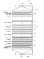
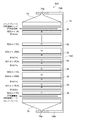
- FIG. 26 is a front view schematically showing a conventional fuel cell stack 920.
- 27 and 28 are plan views of a type CA separator 921 in a conventional fuel cell stack 920.
- FIG. 27 is a plan view seen from the fuel cell gas supply diffusion layer (cathode gas supply diffusion layer) 942 side
- FIG. 28 is seen from the fuel cell gas supply diffusion layer (anode gas supply diffusion layer) 941 side.
- FIG. 29 is a sectional view taken along line AA in FIG.
- a conventional fuel cell stack 920 includes a plurality of separators having a structure in which a gas supply diffusion layer for a fuel cell made of a porous body layer is provided on at least one surface of a metal plate 30 (see FIG. A type CA separator 921, a type A separator 922, a type C separator 923, and a type AW separator 924) are stacked.
- A in the type CA separator 921, the type A separator 922, and the type AW separator 924 represents the gas supply diffusion layer (anode gas supply diffusion layer) 941 for the fuel cell, and the type CA separator 921 and type C.
- the fuel cell gas supply diffusion layers 941 and 942 formed of the porous body layer are formed on the separator itself, so that the fuel cell gas is supplied to the fuel cell gas supply diffusion layer. Can diffuse uniformly over the entire surface. As a result, the fuel cell gas can be supplied uniformly over the entire surface of the membrane electrode assembly (MEA) 81, and the power generation efficiency of the fuel cell can be increased as compared with the conventional case.
- MEA membrane electrode assembly
- an object of the present invention is to provide a fuel cell gas supply diffusion layer, a fuel cell separator, and a fuel cell stack, which can increase the power generation efficiency of the fuel cell as compared with the prior art.
- a gas supply diffusion layer for a fuel cell is a gas supply diffusion layer for a fuel cell, is capable of gas permeation and diffusion, and has a conductive sheet-like porous body layer.
- a plurality of gas flow channel grooves formed in parallel on one surface of the porous body layer, and each of which is formed in a zigzag shape or a wave shape from the inflow side to the outflow side of the gas.
- a first rectangular region R1 circumscribing one gas channel groove among the plurality of gas channel grooves, a first rectangular region R1 circumscribing one gas channel groove; The first rectangular region R1 and the second rectangular region overlap with a second rectangular region R2 that circumscribes the gas channel groove adjacent to the one gas channel groove.
- An overlapping region R3 overlapping with R2 is a cross section of the plurality of gas flow channel grooves. Also present at any depth position of said plurality of gas flow path grooves regardless of Jo.
- a fuel cell separator is a fuel cell separator comprising a gas shielding plate and a fuel cell gas supply diffusion layer disposed on at least one surface of the gas shielding plate,
- the fuel cell gas supply diffusion layer is the fuel cell gas supply diffusion layer of the present invention, and the gas supply diffusion layer for the fuel cell has the plurality of gas flow channel grooves positioned on the gas shielding plate side.
- the gas flow path is constituted by the gas flow path groove and the gas shield plate.
- a fuel cell stack according to an embodiment of the present invention is a fuel cell stack in which a fuel cell separator and a membrane electrode assembly are laminated, and the fuel cell separator is for the fuel cell of the present invention.
- the fuel cell separator and the membrane electrode assembly are separators on the surface of the fuel cell gas supply diffusion layer where the gas channel grooves are not formed. They are stacked in a positional relationship.
- the power generation efficiency of the fuel cell can be made higher than before, and further, the drainage performance is better than before.
- a fuel cell gas supply diffusion layer, a fuel cell separator, and a fuel cell stack are obtained.
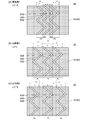
- FIG. 5 is a cross-sectional view of FIG. 4. It is a figure which shows the planar structure of the groove
- FIG. 7 is a plan view of a fuel cell gas supply diffusion layer 42a according to Modification 1.
- FIG. 10 is a plan view of a fuel cell gas supply diffusion layer 42b according to Modification 2.
- FIG. 14 is a plan view of a fuel cell gas supply diffusion layer 42c according to Modification 3.
- FIG. 10 is a plan view of a fuel cell gas supply diffusion layer 42d according to Modification 4.
- FIG. 10 is a plan view of a fuel cell gas supply diffusion layer 42d according to Modification 4.
- FIG. 10 is a plan view of a fuel cell gas supply diffusion layer 42e according to Modification 5.
- 14 is a plan view of a fuel cell gas supply diffusion layer 42f according to Modification 6.
- FIG. 14 is a plan view of a fuel cell gas supply diffusion layer 42g according to Modification 7.
- FIG. 14 is a plan view of a fuel cell gas supply diffusion layer 42h according to Modification 8.
- FIG. 10 is a plan view of a fuel cell gas supply diffusion layer 42i according to Modification 9.
- 14 is a plan view of a fuel cell gas supply diffusion layer 42j according to Modification 10.
- FIG. 14 is a plan view of a fuel cell separator 23k according to Modification 11.
- FIG. 14 is a plan view of a fuel cell separator 23L according to Modification 12.
- FIG. 9 is a plan view of a fuel cell separator 921 of type CA in a conventional fuel cell stack 920.
- FIG. 9 is a plan view of a fuel cell separator 921 of type CA in a conventional fuel cell stack 920.
- FIG. 28 is a cross-sectional view taken along line AA in FIG. 27.
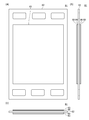
- FIG. 1 is a front view schematically showing a fuel cell stack 20 according to an embodiment.
- FIG. 2 is a side view schematically showing the fuel cell stack 20 according to the embodiment.
- the fuel cell stack 20 is a polymer electrolyte fuel cell (PEFC: Polymer Electrolyte Fuel Cell).
- PEFC Polymer Electrolyte Fuel Cell
- the fuel cell stack 20 has a plurality of single cells.
- Each cell of the fuel cell stack 20 includes a membrane electrode assembly 81, an element constituting the cathode side and an element constituting the anode side with the membrane electrode assembly 81 interposed therebetween.
- the fuel cell separator 21 has a cathode gas supply diffusion layer C formed on one surface of a metal plate 30 as a gas shielding plate, and an anode gas supply diffusion layer A formed on the other surface (type CA separator). ).
- the fuel cell separator 22 has an anode gas supply diffusion layer A formed on one surface of a metal plate 30 (type A separator).
- a cathode gas supply diffusion layer C is formed on one surface of a metal plate 30 (type C separator).
- the cathode gas supply diffusion layer C is formed on one surface of the metal plate 30, and the cooling water supply diffusion layer W is formed on the other surface (type CW separator).
- Each cell is arranged so that the cathode side and the anode side alternate.
- the cathode gas supply diffusion layer C and the anode gas supply diffusion layer A are provided to face each other with a membrane electrode assembly (MEA) 81 interposed therebetween.
- MEA membrane electrode assembly
- a cooling water supply diffusion layer W that supplies cooling water every time two single cells are arranged is provided.
- the cooling water supply diffusion layer W may be provided every other single cell, or every three or more.
- Fuel cell separators 21 to 24 are combined and laminated so that the cooling water supply diffusion layer W faces the metal plate 30 (preferably the metal plate 30 in the type A or type C separator).
- the anode gas supply diffusion layer A is formed on one surface of the metal plate 30, and the cooling water supply diffusion is formed on the other surface. It may be provided with a layer W formed (type AW separator). Further, a separator (type W separator) in which the cooling water supply diffusion layer W is formed on one surface of the metal plate 30 may be provided. Moreover, the separator by which the cooling water supply diffusion layer W was formed in both surfaces of the metal plate may be provided. Details of the configuration of each fuel cell separator will be described later.
- Current collector plates 27A and 27B are disposed at both ends of the stacked cells. Further, end plates 75 and 76 are disposed outside the current collecting plates 27A and 27B via insulating sheets 28A and 28B. The fuel cell separators 21 to 24 are pressed from both sides by end plates 75 and 76. For the fuel cell separators located at both ends of the fuel cell stack 20 and in contact with the current collector plates 27A and 27B, the metal plate 30 (corrosion resistant layer) is preferably directed outward.
- the fuel cell separators 21 to 24, the membrane electrode assembly 81, the current collector plates 27A and 27B, the insulating sheets 28A and 28B, and the end plates 75 and 76 are shown for easy understanding. Although depicted spaced apart, they are intimately joined to each other in the order shown.
- the method for joining is not particularly limited.
- the members may be joined only by pressing the members from both sides with the end plates 75, 76, or the respective members may be joined from both sides by the end plates 75, 76 after bonding the appropriate positions of the members with an adhesive. It may be joined by pressing, or may be joined by other methods.
- Each of the fuel cell separators 21 to 24, the membrane electrode assembly 81, the current collecting plates 27A and 27B, the insulating sheets 28A and 28B, and the like have a thickness of about 100 ⁇ m to about 10 mm, for example. Each figure in each embodiment of the present specification is drawn with exaggerated thickness.
- An anode gas supply port 71A, a cathode gas discharge port 72B, and a cooling water discharge port 73B are provided at one end of the anode side end plate 75, respectively.
- an anode gas discharge port 71B, a cathode gas supply port 72A, and a cooling water supply port 73A are the ends of the cathode side end plate 76 (the side opposite to the one end of the end plate 75)). (Shown collectively in broken lines).
- Corresponding fluid supply pipes and discharge pipes are connected to the supply ports and the discharge ports, respectively.
- Each of the fuel cell separators 21 to 24 has an anode gas inlet 61A communicating with the anode gas supply port 71A, a cathode gas (and product water) outlet 62B communicating with the cathode gas outlet 72B, and cooling water.
- a cooling water outlet 63B communicating with the discharge port 73B is provided.
- Each of the fuel cell separators 21 to 24 has an anode gas outlet 61B communicating with the anode gas discharge port 71B, a cathode gas inlet 62A communicating with the cathode gas supply port 72A, and a cooling water supply port 73A.
- a cooling water inlet 63 ⁇ / b> A communicating with the cooling water is provided.
- the cathode gas, the anode gas, and the cooling water are supplied through the anode gas supply port 71A, the cathode gas supply port 72A, and the cooling water supply port 73A.
- the cathode gas supply port 72A In the embodiment, a case where hydrogen gas is used as the anode gas and air is used as the cathode gas is illustrated.
- FIG. 3 is a view for explaining a membrane electrode assembly (MEA) 81.
- 3A is a plan view of the membrane electrode assembly 81
- FIG. 3B is a front view of the membrane electrode assembly 81
- FIG. 3C is a side view of the membrane electrode assembly.
- the membrane electrode assembly 81 is arranged on an electrolyte membrane (PEM) 82, catalyst layers (CL) 85 arranged on both surfaces of the electrolyte membrane 82, and on the outer surface of each catalyst layer 85.
- the microporous layer (MPL) 83 is provided.
- a structure composed of the electrolyte membrane 82 and the catalyst layers 85 disposed on both sides thereof is referred to as a catalyst coated electrolyte membrane (Catalyst Coated Membrame: CCM).
- the microporous layer 83 has pores (pores) with a diameter smaller than that of the porous body layer 40.
- the microporous layer 83 can be omitted.
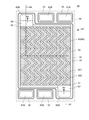
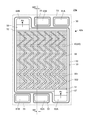
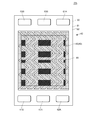
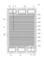
- FIG. 4 is a plan view of the type C fuel cell separator 23 as viewed from the metal plate 30 side. However, in FIG. 4, the illustration of the metal plate 30 is omitted for easy understanding of the flow path pattern of the fuel cell separator 23.
- FIG. 5 is a cross-sectional view of FIG. 5A is a cross-sectional view along A1-A4 in FIG. 4 (however, the A2-A3 portion is omitted), and FIG. 5B is a cross-sectional view along A2-A3 in FIG. In FIG.
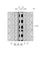
- FIG. 6 is a diagram showing a planar structure of the gas flow channel groove 55.
- FIG. 7 is a diagram showing a planar structure and a cross-sectional structure of the gas channel groove 55.
- FIG. 7A is a plan view
- FIG. 7B is a cross-sectional view taken along the line AA in FIG. 7A.
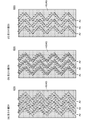
- FIG. 8 is a diagram showing a planar structure of the gas flow path groove 55 at different depth positions.
- FIG. 8A shows a planar structure of the gas flow path groove 55 at the depth position D1 (depth position on the surface of the porous body layer 40 (or the gas flow path groove 55))
- FIG. 8C shows the planar structure of the gas channel groove 55 at the depth position D2 (a depth position that is half the depth of the gas channel groove 55), and FIG.
- the planar structure of the gas channel groove 55 at the depth position at the bottom of the channel groove 55 is shown.
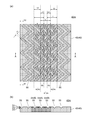
- reference numeral 55 indicates a gas flow path groove
- reference numeral 55A indicates one gas flow path groove among the gas flow path grooves 55
- reference numeral 55B indicates one gas flow path groove 55A.
- the gas channel groove adjacent to is shown. Accordingly, since one gas flow channel groove 55A is also a gas flow channel groove 55, it may be referred to as a gas flow channel groove 55 (55A). Since the flow channel groove 55B is also the gas flow channel groove 55, the gas flow channel groove 55 (55B) may be denoted. In FIG.
- the area surrounded by the thick solid line is the first rectangular area R1
- the area surrounded by the thick broken lines on the left and right is the second rectangular area R2
- the first rectangular area R1 and the second rectangular area A region where the region R2 overlaps is an overlapping region R3, which is shown with a darker color.
- Reference numeral R denotes a rectangular region that circumscribes each gas passage groove among the plurality of gas passage grooves 55
- reference symbol R1 denotes a first rectangular region that circumscribes one gas passage groove 55A
- Reference numeral R2 denotes a second rectangular area circumscribing the gas flow path groove 55B adjacent to one gas flow path groove 55A
- reference numeral R3 denotes an overlap where the first rectangular area R1 and the second rectangular area R2 overlap.
- the first rectangular area R1 is also the rectangular area R, it may be referred to as the first rectangular area R (R1), and since the second rectangular area R2 is also the rectangular area R, the second rectangular area R Sometimes referred to as (R2). Further, in FIG. 7A, the symbol L ⁇ b> 2 indicates the arrangement pitch of the gas flow channel grooves 55.
- FIG. 7 and 8 show the flow of the cathode gas.
- the arrow in the gas flow channel groove 55 is the flow along the gas flow channel groove 55
- the vertical upward arrow written in the porous body layer 40 is the gas flow.
- This is a cathode gas flow (downflow gas flow) extruded from the channel groove 55 into the porous body layer 40 (gas diffusion layer 43).
- FIG. 7B the arrows in the lateral direction and the downward direction (the direction toward the membrane electrode assembly side) indicated in the porous body layer 40 indicate the porous body layer 40 (from the gas channel groove 55).
- FIG. 9 is a diagram illustrating the relationship between the first rectangular region R1, the second rectangular region R2, and the overlapping region R3.
- the fuel cell separator 23 has a structure in which a fuel cell gas supply diffusion layer 42 is formed on one surface of the metal plate 30.
- the metal plate 30 is hatched to indicate a cross section.
- the metal plate 30 is preferably a metal composed of one or more of Inconel, nickel, gold, silver and platinum, or a metal plating or clad material on an austenitic stainless steel plate. Corrosion resistance can be improved by using these metals.
- a cathode gas inlet 62A, a cooling water inlet 63A, and an anode are arranged at one end (the lower part in FIG. 4) of the metal plate 30 in the order of right, center, and left in FIG.
- a gas outlet 61B is provided.
- a cathode gas outlet 62B, a cooling water outlet 63B, and an anode gas inlet 61A are provided at the other end (upper part of FIG. 4) in the order of left, center, and right in FIG.
- Each of the inlets 61A, 62A, 63A, each of the outlets 61B, 62B, 63B, and the periphery of the formation region of the fuel cell gas supply diffusion layer 42 is surrounded by an electron conductive or non-electron conductive dense frame 32. being surrounded.
- the dense frame 32 prevents leakage of anode gas, cathode gas and cooling water.
- the respective inlets 61 ⁇ / b> A, 62 ⁇ / b> A, 63 ⁇ / b> A, the outlets 61 ⁇ / b> B, 62 ⁇ / b> B, 63 ⁇ / b> B, and the fuel cell gas supply diffusion layer 42 are formed.
- a groove 33A is formed (not shown in FIG. 4).
- a gasket (a sealing material such as a packing and an O-ring) 33 is disposed in the groove 33A.
- the entire surface of the metal plate 30 has a corrosion-resistant layer having electronic conductivity (Not shown in FIG. 5).
- Corrosion-resistant layers may be formed on the inner peripheral surfaces of the inflow ports 61A, 62A, and 63A and the outflow ports 61B, 62B, and 63B.
- Corrosion-resistant layers may be formed on the side surfaces and end surfaces of the metal plate 30.
- the corrosion-resistant layer is preferably a dense layer having the same composition as the dense frame 32 and has an action of suppressing corrosion of the metal plate 30.
- the gasket 33 is joined to another fuel cell separator, membrane electrode assembly 81 or current collector plate 27A, Close contact with 27B to suppress fluid leakage.
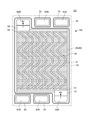
- the fuel cell separator 23 is a type C fuel cell separator. As shown in FIGS. 4 and 5, the cathode gas is supplied and diffused to the central portion of one surface of a rectangular metal plate 30 as a substrate. A fuel cell gas supply diffusion layer 42 is formed.
- the fuel cell gas supply diffusion layer 42 is capable of gas permeation and diffusion, and has a conductive sheet-like porous body layer 40 in parallel on one surface of the porous body layer 40, and A plurality of gas passage grooves 55 each formed in a zigzag shape or a wave shape from the gas inflow side to the outflow side, and gas diffusion that is a portion of the porous body layer 40 other than the gas passage groove 55 And a layer 43 (see FIG. 4).
- the first gas flow channel groove 55 is circumscribed first.
- the rectangular region R1 and the second rectangular region R2 that circumscribes the gas flow channel groove adjacent to the one gas flow channel groove overlap each other along the contacted region (see FIGS. 6 and 9).
- the overlapping region R3 where the first rectangular region R1 and the second rectangular region R2 overlap each other has any depth position D1 of the gas channel grooves 55 regardless of the cross-sectional shape of the gas channel grooves 55. It exists also in D2 and D3 (see FIGS. 7 and 8).
- the “rectangular region” is a rectangular region R that circumscribes each gas channel groove among a plurality of gas channel grooves (see FIGS. 6 and 7), but is porous.
- One or a plurality of gas pressure equalization grooves are formed in the body layer 40 across the entire width direction orthogonal to the direction from the gas inflow side to the outflow side so as to intersect with the plurality of gas flow path grooves.
- each rectangular region R formed in the region divided by the gas pressure equalizing groove also has a difference in width and / or length. It is assumed that it is included in the rectangular area of the present invention.
- the “downflow region” refers to a region of the rectangular region excluding the gas flow channel groove 55, and in the downflow region, a large amount of gas has a shortest distance toward the outflow side. It will flow along the route.
- “from the gas inflow side to the outflow side” means “almost along the gas flow direction”, and the direction “from the gas inflow side to the outflow side” is This is the direction of gas flow in the porous body layer 40 when viewed as the whole porous body layer 40. This is because when the cathode gas inlet 62A and the cathode gas outlet 62B are arranged at diagonal positions on the metal plate 30 as in the fuel cell gas supply diffusion layer 42 according to the embodiment.
- the path does not have to be formed along the above diagonal line, and the direction “from the gas inflow side to the outflow side” as in the embodiment is “a porous body when viewed as the entire porous body layer 40”
- the gas flow channel groove may be formed, or may be formed along other directions.
- the gas pressure equalization groove is substantially in the direction of “from the gas inflow side to the outflow side”, that is, the gas flow direction in the porous body layer 40 when viewed as the entire porous body layer 40. It is good to arrange so that it may orthogonally cross.
- a rectangular region circumscribing the gas flow channel groove 55 is defined as a rectangular region R.
- the first rectangular region R1 and the second rectangular region R2 are configured so as to overlap with each other, that is, as shown in FIG.
- the arrangement pitch L2 of the (rectangular region R) and the width L of the rectangular region R are set to satisfy the relationship of L2 ⁇ L
- the adjacent zigzag gas The other crest side protrudes to one trough side of the flow path groove 55 to the extent that the flow paths do not overlap each other.
- the end of the porous body layer 40 includes the vicinity of the end of the porous body layer 40.
- the width L1 of the overlapping region R3 and the width L of the rectangular region R are “L1 ⁇ 0. 1 ⁇ L ”is preferably satisfied,“ L1 ⁇ 0.2 ⁇ L ”is more preferable, and“ L1 ⁇ 0.3 ⁇ L ”is more preferable (FIG. 7). reference.).
- the porous body layer 40 includes a mixture of a conductive material (preferably a carbon-based conductive material) and a polymer resin.
- a conductive material preferably a carbon-based conductive material
- the fluid resistance of the porous body layer 40 depends on the porosity of the porous body layer and the area of the surface through which the fluid flows. As the porosity increases, the fluid resistance decreases. If the area through which the fluid flows increases, the fluid resistance decreases.
- the porosity of the porous body layer 40 is about 50 to 85%.
- the porosity of the porous body layer 40 is about 30 to 85%.
- the porosity of the porous body layer 40 is configured as described above, the cathode between the gas passage groove 55 and the porous body layer 40 via the inner surface of the gas passage groove 55.
- a large amount of fuel cell gas can be uniformly supplied to the membrane electrode assembly, and cathode gas that has not been used during power generation
- water vapor and condensed water generated during power generation can be efficiently discharged out of the gas channel groove.
- a gas permeation filter such as a gas impervious layer made of metal, ceramics, resin, or the like in which many fine gas flow holes are opened on the inner surface of the gas flow channel groove 55.
- the porosity of the fuel cell gas supply diffusion layer 42 can be adjusted, and consequently the movement resistance of the fuel cell gas supply diffusion layer 42 can be adjusted. .
- the content of the carbon-based conductive material is increased, the movement resistance is decreased (the porosity is increased).
- the content of the carbon-based conductive material is lowered, the movement resistance is increased (the porosity is decreased).
- the corrosion-resistant layer and the dense frame 32 are also a mixture of a carbon-based conductive material and a polymer resin, and are preferably densified while ensuring conductivity by an appropriate content of the carbon-based conductive material.
- the carbon-based conductive material is not particularly limited.
- graphite, carbon black, diamond-coated carbon black, silicon carbide, titanium carbide, carbon fiber, carbon nanotube, and the like can be used.
- the polymer resin any of a thermosetting resin and a thermoplastic resin can be used. Examples of the polymer resin include phenol resin, epoxy resin, melamine resin, rubber-based resin, furan resin, vinylidene fluoride resin, and the like.
- An inflow passage 57 is formed between the cathode gas inlet 62A and the region where the porous body layer 40 is formed (see FIG. 4).
- An outflow passage 58 is formed between the cathode gas outlet 62B and the region where the porous body layer 40 is formed.
- These inflow passage 57 and outflow passage 58 are for supporting the membrane electrode assembly 81 or its frame 81A. Accordingly, any structure that can smoothly flow the cathode gas and can support the membrane electrode assembly 81 may be used. For example, a porous layer having a very large porosity or a structure in which a large number of support columns are arranged may be used.
- An elongated inflow side groove 51 is formed along the width direction of the metal plate 30 in a region facing the inflow passage 57 in the porous body layer 40.
- An elongated outflow side groove 52 is also formed in the region facing the outflow passage 58 in the porous body layer 40 along the width direction of the metal plate 30.
- the inflow side groove 51 and the outflow side groove 52 can be omitted.
- the porous body layer 40, the inflow passage 57, and the outflow passage 58 are formed at the same height (thickness) as the dense frame 32, as shown in FIG.
- a plurality of gas flow channel grooves 55 formed of voids are provided on the surface of the fuel cell gas supply diffusion layer 42 facing the metal plate 30, and the plurality of gas flow channel grooves 55 and the metal plate are provided.
- a plurality of gas flow paths are formed in the gap with 30.
- a plurality of gas flow channel grooves 55 are formed with a predetermined gap.
- Each gas flow channel groove 55 communicates with the inflow passage 57 via the inflow side groove 51 on the inflow side, and communicates with the outflow passage 58 via the outflow side groove 52 on the outflow side.
- the number and structure of the gas channel grooves 55 are not limited to those shown in the drawing.
- the width of the porous body layer 40 is, for example, 30 mm, depending on the type and size of the transportation equipment. About 300 mm.
- the width W of the gas channel groove 55 is, for example, about 0.3 mm to 2 mm.
- the thickness of the porous body layer 40 is, for example, about 150 to 400 ⁇ m, and the depth of the gas flow path groove 55 is, for example, about 100 to 300 ⁇ m.
- the bottom of the gas flow path groove and the other of the porous body layer 40 The distance from the surface (ceiling thickness) is, for example, about 100 to 300 ⁇ m.
- the size is not limited to the above-described size, and the required performance, etc. Depending on the size, an appropriate size can be used.
- the gas channel groove 55 has a zigzag shape. That is, the gas flow channel groove 55 includes a straight portion 551 and a corner portion 552 that changes the direction of air flow.
- the length of the straight line portion 551 and the angle of the corner portion 552 are not limited to those shown in the drawing.
- the angle of the corner portion 552 is substantially a right angle, but may be an acute angle or an obtuse angle. Further, the corner portion 552 may be appropriately chamfered or rounded.
- each straight portion 551 and the shape of each corner portion 552 are equal.
- a plurality of rectangular regions (rectangular regions) R that circumscribe each gas channel groove among the plurality of gas channel grooves 55 are defined in plan view, one gas is defined.
- a first rectangular region R1 circumscribing the flow channel groove 55 and a second rectangular region R2 circumscribing the gas flow channel groove 55 adjacent to one gas flow channel groove overlap each other along the region in contact with the first rectangular region R1.
- an overlapping region R3 where the first rectangular region R1 and the second rectangular region R2 overlap is present at any depth position D1, D2, D3 of the plurality of gas flow channel grooves 55.
- the fuel cell gas supply diffusion layer 41 in the type A fuel cell separator 22 basically has the same configuration as the fuel cell gas supply diffusion layer 42. However, since the gas supplied to the fuel cell gas supply diffusion layer is hydrogen gas, the porosity is lower than that of the fuel cell gas supply diffusion layer 42 and the thickness is smaller (FIG. 10B described later). reference.).
- the fuel cell gas supply diffusion layer 41 and the fuel cell gas supply diffusion layer 42 are used as the fuel cell gas supply diffusion layer (see FIG. 10A described later).
- the type CW fuel cell separator 24 is obtained by forming a cooling water supply diffusion layer on the surface of the type C fuel cell separator 23 where the fuel cell gas supply diffusion layer 42 is not formed. 10 (c)).
- a cooling water supply diffusion layer is formed on the surface of the type A fuel cell separator 22 where the fuel cell gas supply diffusion layer 41 is not formed (see FIG. 10 (d).)
- protons H +
- anode gas hydrogen gas
- Protons diffuse through the membrane electrode assembly 81 and move to the oxygen electrode side, and react with oxygen to produce water.
- the generated water is discharged from the oxygen electrode side.
- the air flowing in from the cathode gas inlet 62A passes through the inflow passage 57 and the inflow side groove 51, and then flows into the gas. It flows into the channel groove 55.
- Part of the air flowing into the inflow side groove 51 enters the gas flow path groove 55 and enters the porous body layer 40 (gas diffusion layer 43) from the gas flow path groove 55, and the other part is porous.
- the porous body layer 40 (gas diffusion layer 43) enters the porous body layer 40 (gas diffusion layer 43) directly from the end face of the porous body layer 40 (gas diffusion layer 43), and diffuses in the porous body layer 40 (gas diffusion layer 43).
- Gas that has not been used for power generation (unused oxygen gas and nitrogen gas) and water generated during power generation (water vapor or condensed water) are porous body layer 40 (gas diffusion layer 43), gas channel groove 55, and outflow. It flows out to the outflow passage 58 through the side groove 52.
- the oxygen gas, nitrogen gas and water flowing out to the outflow passage 58 are finally discharged from the outflow passage 58 through the cathode gas outlet 62B and the cathode gas outlet 72B.
- all the water is not discharged and a part of the water stays in the porous body layer 40 (gas diffusion layer 43).
- the fuel cell gas supply diffusion layer 42 Since the fuel cell gas supply diffusion layer 42 according to the embodiment has the characteristics as described above, water (water vapor or condensed water) generated in the membrane electrode assembly during power generation is converted into the porous body layer 40 and the gas flow.
- the gas can be efficiently discharged out of the gas channel groove through the channel groove 55. Further, in the downflow region, water can be efficiently discharged out of the gas flow channel groove by being pushed out by the downflow gas flow.
- the plurality of gas flow channel grooves 55 are formed on one surface of the porous body layer 40, Since the fuel cell gas is always supplied to the membrane electrode assembly 81 disposed on the other surface through the porous body layer 40, a plurality of gas flow paths are formed from one surface of the porous body layer to the other. The fuel cell gas can be supplied more uniformly to the membrane electrode assembly than in the case of opening over the surface. Further, according to the fuel cell gas supply diffusion layer 42 according to the embodiment, the plurality of gas flow channel grooves 55 are formed in a zigzag shape on one surface of the porous body layer 40 from the gas inflow side to the outflow side.
- the fuel cell gas supply diffusion layer 42 in the first rectangular region R1 that circumscribes one gas flow channel 55A among the plurality of gas flow channel grooves 55, the one gas A part of the fuel cell gas flowing in the flow channel groove 55A enters the porous body layer 40 to form a so-called downflow region in the first rectangular region R1, and the one gas flow channel groove 55A described above.
- a part of the fuel cell gas flowing in the gas flow passage groove 55B adjacent to the porous body layer 40 enters the so-called downflow region in the second rectangular region R2, and these first rectangular regions R1 and Since the second rectangular region R2 overlaps with the region in contact with the second rectangular region R2 (see FIGS. 6 and 7), the fuel cell gas supply path supplied to the porous body layer 40 has no gap in the plane. Gas fuel cell gas to be dispersed It can be further uniformly supplied to the membrane electrode assembly 81.
- the overlapping region R3 where the first rectangular region R1 and the second rectangular region R2 overlap is located at which depth position of the plurality of gas flow channel grooves 55. Since it also exists in D1, D2, and D3 (see FIG. 7 and FIG. 8), the fuel cell gas supply path supplied to the porous body layer 40 has any depth position D1 of the gas flow channel groove 55. , D2 and D3 are dispersed without any gap in the plane, so that the fuel cell gas can be supplied more uniformly to the membrane electrode assembly.
- the fuel cell gas supply diffusion layer 42 can uniformly supply a larger amount of fuel cell gas to the membrane electrode assembly 81 than in the prior art.
- the fuel cell gas supply diffusion layer can be improved.
- the fuel cell gas in this case, cathode gas (oxygen gas, nitrogen gas)
- the fuel cell gas in this case, cathode gas (oxygen gas, nitrogen gas)
- it can be efficiently discharged out of the gas flow channel groove 55 through the porous body layer 40 and the gas flow channel groove 55, and is used for power generation in the downflow region by being pushed out by the downflow gas flow.
- the fuel cell gas in this case, the cathode gas (oxygen gas, nitrogen gas)
- the movement resistance of the fuel cell gas is lower than in the prior art. This makes it possible to maintain the reaction gas concentration at a high level, and thus to provide a fuel cell gas supply diffusion layer that can increase the power generation efficiency of the fuel cell as compared with the prior art.
- the fuel cell gas supply diffusion layer 42 since the fuel cell gas supply diffusion layer 42 according to the embodiment has the above-described characteristics, the water vapor or the condensed water generated in the membrane electrode assembly 81 during power generation is converted into the porous body layer 40 and the gas flow. Since the gas can be efficiently discharged to the outside of the gas passage groove 55 through the passage groove 55, the steam or condensed water is pushed out by the downflow gas flow in the downflow region. Therefore, it becomes a gas supply diffusion layer for a fuel cell that is more excellent in drainage than before.
- the width L1 of the overlapping region R3 and the width L of the rectangular region satisfy the relationship of “L1 ⁇ 0.1 ⁇ L”.
- the plane area ratio of the overlapping region R3 occupying the fuel cell gas supply diffusion layer 42 can be increased, and the fuel cell gas can be supplied to the membrane electrode assembly 81 more uniformly.
- the fuel cell separator 23 is a fuel cell separator including a metal plate 30 and a fuel cell gas supply diffusion layer disposed on at least one surface of the metal plate 30.
- the gas supply diffusion layer is the fuel cell gas supply diffusion layer 42 according to the embodiment, and the fuel cell gas supply diffusion layer 42 is made of metal such that the plurality of gas flow channel grooves 55 are located on the metal plate 30 side. Since the gas flow path is constituted by the gas flow path groove 55 and the metal plate 30, it is possible to increase the power generation efficiency of the fuel cell as compared with the prior art.
- the fuel cell separator is excellent in drainage.
- the fuel cell stack 20 according to the embodiment is a fuel cell stack in which a fuel cell separator and a membrane electrode assembly are stacked, and the fuel cell separator is the fuel cell separator 23 according to the embodiment.
- the fuel cell separator 23 and the membrane electrode assembly 81 are formed on the surface of the fuel cell gas supply diffusion layer 42 where the plurality of gas flow channel grooves 55 are not formed. Since they are stacked in a positional relationship, the fuel cell power generation efficiency can be made higher than that of the conventional one, and furthermore, a fuel cell stack having better drainage than the conventional one can be obtained.
- the corrosion-resistant layer, the dense frame 32, the fuel cell gas supply diffusion layer 42, and the like are formed by isotropic pressure.
- a thermosetting resin a thermoplastic resin may be used
- carbon-based conductive material powder and carbon fiber depending on the situation
- resin powder and volatile solvent are kneaded to form a paste.
- Many types of pastes such as a corrosion-resistant layer, a dense frame, and a fluid supply diffusion layer, are prepared.
- a corrosion-resistant layer, a dense frame 32 pattern, a fuel cell gas supply diffusion layer 42 pattern, and the like are sequentially formed on the metal plate 30 by printing, stamping, squeezing, or the like.
- the solvent is volatilized for each pattern formation.
- the whole metal plate 30 on which all the above patterns are formed is put in a soft thin rubber bag, degassed to a vacuum, and then the rubber bag is put in a pressure vessel, and a heating fluid is introduced into the vessel. Press the isotropic pressure to cure the resin.
- the height (thickness) of the dense frame 32 and the fuel cell gas supply diffusion layer 42 the same height (thickness)
- each of these may be selected according to the degree of shrinkage during resin curing. It is preferable to adjust the height (thickness) of the frame, wall, layer, and the like at the time of pattern formation.
- a corrosion-resistant layer can be formed on the metal plate 30, the dense frame 32 and the fuel cell gas supply diffusion layer 42 can be formed on the other side, and finally these can be manufactured by thermocompression bonding.
- the dense frame 32 may be formed simultaneously with the corrosion-resistant layer on the metal plate 30.
- a corrosion-resistant layer and a dense frame 32 are formed on the metal plate 30, and then in the second stage, the paste of the fuel cell gas supply diffusion layer 42 is sequentially printed on the corrosion-resistant layer of the metal plate 30 and dried. After making it harden
- the following manufacturing method can be used. Green before curing after kneading carbon fiber (CF), a small amount of black smoke fine particles (GCB), and thermoplastic or thermosetting resin to form a binder, or a fiber-forming resin.
- CF carbon fiber
- GCB black smoke fine particles
- thermoplastic or thermosetting resin to form a binder, or a fiber-forming resin.
- a stamp mold having a shape corresponding to the inflow passage 57, the outflow passage 58, the inflow side groove 51, the outflow side groove 52, and the gas flow path groove 55 is pressed against the sheet, and the inflow passage 57, the outflow A passage 58, an inflow side groove 51, an outflow side groove 52, and a gas flow path groove 55 are formed.
- the green sheet is heat treated and bonded to the metal plate 30 on which the corrosion resistant layer is formed.
- the movement resistance (or fluid resistance) of the fuel cell gas supply diffusion layer 42 is the surface area (height (thickness) and width of each layer) orthogonal to the porosity of the porous body layer 40 and the fluid flow direction. Dependent. If the porosity increases, the movement resistance decreases. If the area through which the fluid flows increases, the movement resistance decreases (the movement resistance per unit area is constant).
- the porosity of the fuel cell gas supply diffusion layer is about 30 to 85% for the fuel cell gas supply diffusion layer 42 (for the anode gas), and the fuel cell gas supply diffusion for the cathode gas.
- the layer 41 is about 50 to 85%.
- the manufacturing method described above is also used when manufacturing fuel cell separators other than the fuel cell separator 23 (fuel cell separator 21, fuel cell separator 22, fuel cell separator 24, and fuel cell separator 25). Applicable.
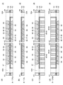
- FIG. 10 is a cross-sectional view of a fuel cell separator (a fuel cell separator 21, a fuel cell separator 22, a fuel cell separator 24, and a fuel cell separator 25) other than the fuel cell separator 23.
- 10A is a sectional view of a fuel cell separator 21 of type CA
- FIG. 10B is a sectional view of a fuel cell separator 22 of type A
- FIG. 10C is a fuel of type CW.
- FIG. 10D is a cross-sectional view of the battery separator 24, and
- FIG. 10D is a cross-sectional view of a fuel cell separator 25 of type AW.
- the fuel cell gas supply diffusion layer of the present invention is applied to the fuel cell gas supply diffusion layer (for cathode gas) 42 and / or the fuel cell gas supply diffusion layer 41 (for anode gas) of the fuel cell separator 21. (See FIG. 10 (a)). Further, the fuel cell gas supply diffusion layer of the present invention can be applied to the fuel cell gas supply diffusion layer 41 (for anode gas) of the fuel cell separator 22 (see FIG. 10B). Further, the fuel cell gas supply diffusion layer of the present invention can be applied to the fuel cell gas supply diffusion layer 42 (for cathode gas) of the fuel cell separator 24 (see FIG. 10C). Further, the fuel cell gas supply diffusion layer of the present invention can be applied to the fuel cell gas supply diffusion layer 41 (for anode gas) of the fuel cell separator 25 (see FIG. 10B).
- the fuel cell gas supply diffusion layer of the present invention is applied to the fuel cell gas supply diffusion layers of the fuel cell separators 21, 22, 24, and 25 as described above, a larger amount than in the conventional case. Since the fuel cell gas can be uniformly supplied to the membrane electrode assembly, it becomes a fuel cell gas supply diffusion layer that can increase the power generation efficiency of the fuel cell as compared with the conventional case.
- FIG. 11 is a view for explaining a planar structure (seen from the metal plate 30 side) of the fuel cell gas supply diffusion layer 42a according to the first modification.
- the metal plate 30 is not shown in order to easily show the flow path pattern of the fuel cell separator 23.
- the fuel cell gas supply diffusion layer 42a according to Modification 1 has basically the same configuration as the fuel cell gas supply diffusion layer 42 according to the embodiment, but the configuration of the gas flow channel groove 55 is an embodiment. This is different from the fuel cell gas supply diffusion layer 42 according to the above. That is, in the fuel cell gas supply diffusion layer 42a according to the first modified example, as shown in FIG.
- the gas channel groove 55 includes the width W1 of the end portion on the inflow side of the gas channel groove 55 and the gas
- the width W2 of the outflow side end of the channel groove 55 satisfies the relationship of “W2 ⁇ W1”.
- the linear velocity of the gas flow in the gas flow channel groove is increased on the outflow end side.
- the downflow ratio is increased, and a larger amount of fuel cell gas can be evenly fed into the porous body layer, and the decrease in the concentration of fuel cell gas in the so-called downflow region can be suppressed even in the outflow region. Can do.
- the width W of the channel groove 55 gradually decreases from the gas inflow side to the outflow side.
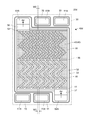
- FIG. 12 is a view for explaining the planar structure of the fuel cell gas supply diffusion layer 42b according to the second modification.
- symbol R4 indicates a “divided overlap region” described later.
- the fuel cell gas supply diffusion layer 42b according to the modified example 2 basically has the same configuration as the fuel cell gas supply diffusion layer 42 according to the embodiment, but includes a gas pressure in addition to the gas flow channel groove. The point where the equalizing grooves are formed is different from the case of the fuel cell gas supply diffusion layer 42 according to the embodiment. That is, in the fuel cell gas supply diffusion layer 42b according to Modification 2, as shown in FIG. 12, the porous body layer 40 has a gas inflow so as to intersect with the plurality of gas flow channel grooves 55.
- One gas pressure equalizing groove 56 is formed over the entire width direction orthogonal to the direction from the side toward the outflow side. Further, when the overlapping region divided by the gas pressure equalizing groove 56 is defined as “divided overlapping region R4”, the divided overlapping region R4 exists at any depth position of the plurality of gas flow channel grooves 55. To do. According to the fuel cell gas supply diffusion layer 42b according to the modified example 2, the gas pressure equalization groove 56 causes the fuel cell gas to flow over the entire width direction perpendicular to the direction from the gas inflow side to the outflow side. The supply amount can be made even.
- the fuel cell gas supply path supplied to the porous body layer is dispersed without any gaps, so that the fuel Battery gas can be supplied more uniformly to the membrane electrode assembly.
- the depth of the gas flow path groove 55 and the depth of the gas pressure equalizing groove 56 are made equal. For this reason, since the gas flow channel groove 55 and the gas pressure equalizing groove 56 can be formed using a mold having the same manufacturing process and a simple structure, the gas pressure equalizing groove is formed. This also has the effect of suppressing an increase in manufacturing cost due to the operation.
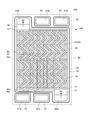
- FIG. 13 is a view for explaining the planar structure of the fuel cell gas supply diffusion layer 42c according to the third modification.
- the fuel cell gas supply diffusion layer 42c according to Modification 3 basically has the same configuration as that of the fuel cell gas supply diffusion layer 42b according to Modification 2, except that the gas flow channel groove 55 has a configuration. This is different from the fuel cell gas supply diffusion layer 42c according to the second modification. That is, in the fuel cell gas supply diffusion layer 42c according to the modified example 3, as shown in FIG. 13, the gas flow path groove 55 has the width W1 of the inflow side end of the gas flow path groove 55 and the gas flow. The width W2 of the outflow side end of the road groove 55 satisfies the relationship “W2 ⁇ W1”.
- the linear velocity of the gas flow in the gas flow channel groove is increased on the outflow end side.
- the downflow ratio is increased, and a large amount of fuel cell gas can be sent evenly into the entire area of the porous body layer. Even in the outflow area, the concentration of fuel cell gas in the so-called downflow area decreases. Can be suppressed.
- steam or condensed water which arises as a reaction product and increases toward the downstream can be discharged
- the width W of the channel groove 55 is gradually narrowed from the gas inflow side to the outflow side, but may be narrowed stepwise.
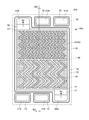
- FIG. 14 is a view for explaining a planar structure of a fuel cell gas supply diffusion layer 42d according to Modification 4.
- the fuel cell gas supply diffusion layer 42d according to the modification 4 has basically the same configuration as the fuel cell gas supply diffusion layer 42b according to the modification 2, but has a planar structure of the gas flow channel groove 55. Is different from the fuel cell gas supply diffusion layer 42b according to the second modification. That is, in the fuel cell gas supply diffusion layer 42d according to the modified example 4, as shown in FIG. 14, the formation density of gas channel grooves 55 at the outflow side end (the number formed per unit area) is the inflow side end. It is higher than the formation density of gas channel grooves 55 (number of formation per unit area) in the part.
- the fuel cell gas is consumed as it flows downstream with the progress of the reaction, so that the supply tends to be reduced.
- the fuel cell gas concentration in the fuel cell can be suppressed from decreasing, and water vapor or condensed water generated as a reaction product and increasing downstream can be effectively discharged.
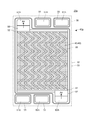
- FIG. 15 is a view for explaining the planar structure of the fuel cell gas supply diffusion layer 42e according to the fifth modification.
- the fuel cell gas supply diffusion layer 42e according to the modified example 5 basically has the same configuration as the fuel cell gas supply diffusion layer 42b according to the modified example 2, but includes a planar structure of the gas flow channel groove 55. Is different from the fuel cell gas supply diffusion layer 42b according to the second modification. That is, as shown in FIG. 15, the fuel cell gas supply diffusion layer 42e according to the modified example 5 has a formation density (unit area) of the gas flow channel grooves 55 at the end on the outflow side, as in the modified example 4.
- the number of formations per unit area) is higher than the formation density (number of formations per unit area) of the gas flow channel grooves 55 at the inflow side end.
- the fuel cell gas supply diffusion layer 42d according to the modified example 5 the fuel cell gas is consumed as it flows downstream with the progress of the reaction, so that the supply is likely to be reduced.
- the fuel cell gas concentration in the fuel cell can be suppressed from decreasing, and water vapor or condensed water generated as a reaction product and increasing downstream can be effectively discharged.
- the vertical zigzag pitch of the gas flow channel groove 55 is made shorter than in the fourth modification.
- FIG. 16 is a view for explaining a planar structure of a fuel cell gas supply diffusion layer 42f according to Modification 6.
- the fuel cell gas supply diffusion layer 42f according to Modification 6 has basically the same configuration as the fuel cell gas supply diffusion layers 42b to 42e according to Modifications 2 to 5, but for gas pressure equalization.
- the number of grooves 56 formed is different from that of the fuel cell gas supply diffusion layers 42b to 42e according to the second to fifth modifications. That is, in the fuel cell gas supply diffusion layer 42f according to Modification 6, as shown in FIG. 16, the number of gas pressure equalization grooves 56 is two.
- the number of gas pressure equalization grooves 56 is two, so that the gas pressure equalization grooves 56 cause the gas inflow side to flow from the gas inflow side.
- the supply amount of the fuel cell gas can be made more uniform over the entire width direction orthogonal to the direction toward the outflow side.
- the width W of the channel groove 55 is gradually reduced from the gas inflow side to the outflow side, but may be gradually reduced.
- FIG. 17 is a view for explaining a planar structure of a fuel cell gas supply diffusion layer 42g according to Modification 7.
- the fuel cell gas supply diffusion layer 42g according to the modified example 7 basically has the same configuration as the fuel cell gas supply diffusion layer 42 according to the embodiment, but the gas flow channel groove on the most inflow side. Is different from the fuel cell gas supply diffusion layer according to the embodiment. That is, in the fuel cell gas supply diffusion layer 42g according to the modified example 7, as shown in FIG. 17, the angle of formation of the gas flow channel groove 55 on the most inflow side is such that the fuel cell gas is in the gas flow channel. The angle is easy to enter the groove 55.
- the angle of formation of the gas flow channel groove 55 located on the most inflow side is such that the fuel cell gas can easily enter the gas flow channel groove 55. Therefore, the movement resistance of the fuel cell gas is reduced, and a larger amount of fuel cell gas can be supplied to the membrane electrode assembly.
- FIG. 18 is a view for explaining the planar structure of the fuel cell gas supply diffusion layer 42h according to Modification 8.
- the fuel cell gas supply diffusion layer 42h according to the modified example 8 basically has the same configuration as the fuel cell gas supply diffusion layer 42 according to the embodiment, but the inflow side end of the gas flow channel groove 55. And the outflow side end are formed at different angles from those of the fuel cell gas supply diffusion layer 42 according to the embodiment. That is, in the fuel cell gas supply diffusion layer 42h according to the modified example 8, as shown in FIG. 18, both the formation angles of the inflow side end and the outflow side end of the gas flow channel groove 55 are gas. The angle is parallel to the direction from the inflow side to the outflow side (longitudinal direction of the metal plate 30).
- both of the formation angles of the inflow side end portion and the outflow side end portion of the gas flow path groove 55 extend from the gas inflow side to the outflow side. Since the angle is parallel to the direction (longitudinal direction of the metal plate 30), the movement resistance during the inflow of the fuel cell gas and the inflow during the outflow is reduced, and the membrane electrode assembly A much larger amount of fuel cell gas can be supplied.
- FIG. 19 is a view for explaining a planar structure of a fuel cell gas supply diffusion layer 42i according to Modification 9.
- the fuel cell gas supply diffusion layer 42i according to the modification 9 has basically the same configuration as the fuel cell gas supply diffusion layer 42h according to the modification 8, but the inflow side of the gas flow channel groove 55.
- the formation width of the end portion and the outflow side end portion is different from that of the fuel cell gas supply diffusion layer 42h according to the modified example 8. That is, in the fuel cell gas supply diffusion layer 42i according to the modified example 9, as shown in FIG. 19, the formation width of the inflow side end and the outflow side end of the gas flow channel groove 55 is related to the modified example 8. It is wider than the case of the fuel cell gas supply diffusion layer 42h.
- the formation width of the inflow side end and the outflow side end of the gas flow path groove 55 is the fuel cell gas supply diffusion layer 42h according to the modification 8. Since it has a taper shape that is wider than that in the case of, and becomes wider toward the end, movement resistance at the time of inflow and outflow of fuel cell gas is further reduced, and membrane electrode joining A larger amount of fuel cell gas can be supplied to the body.
- FIG. 20 is a view for explaining the planar structure of the fuel cell gas supply diffusion layer 42j according to Modification 10.
- the fuel cell gas supply diffusion layer 42j according to Modification 10 has basically the same configuration as the fuel cell gas supply diffusion layer 42 according to the embodiment, but the planar shape of the gas flow channel groove 55 Is different from the fuel cell gas supply diffusion layer 42 according to the embodiment. That is, in the fuel cell gas supply diffusion layer 42j according to Modification 10, as shown in FIG. 20, the planar shapes of the plurality of gas flow channel grooves 55 are wavy. According to the fuel cell gas supply diffusion layer 42j according to the modification 10, the planar shape of the gas flow channel groove 55 is different from that of the fuel cell gas supply diffusion layer 42 according to the embodiment, but according to the embodiment.
- the fuel cell gas supply path supplied to the porous body layer is widely dispersed in the plane, so that a plurality of gas flow channel grooves are formed in the gas.
- the fuel cell gas can be supplied more uniformly to the membrane electrode assembly than in the case where it is formed linearly from the inflow side to the outflow side.
- FIG. 21 is a view for explaining a planar structure of a fuel cell separator 23k according to the eleventh modification.
- the fuel cell separator 23k according to the modification 11 is a C-type fuel cell separator, and basically has the same configuration as the fuel cell separator 23 according to the embodiment, but has a cathode gas inlet 62A.
- the planar structure including the cathode gas outlet 62B, the anode gas inlet 61A and the anode gas outlet 61B, and the cooling water inlet 63A and the cooling water outlet 63B is different from that of the fuel cell separator 23 according to the embodiment. That is, in the fuel cell separator 23k according to the modified example 11, as shown in FIG.
- cathode gas inlet 62A and the cathode gas outlet 62B are formed at both longitudinal ends of the metal plate 30, respectively.
- the inlet 61 ⁇ / b> A and the anode gas outlet 61 ⁇ / b> B, the cooling water inlet 63 ⁇ / b> A and the cooling water outlet 63 ⁇ / b> B are respectively formed at both lateral ends of the metal plate 30.
- the fuel cell gas supply diffusion layer can be further improved in power generation efficiency of the fuel cell.
- the fuel cell gas supply diffusion layer 23k according to the modified example 11 the water vapor or condensed water generated in the membrane electrode assembly during power generation can be efficiently discharged out of the gas flow channel groove. It becomes a gas supply diffusion layer for a fuel cell that is further excellent in drainage.
- the membrane electrode assembly 81 having the catalyst layer 85 having substantially the same area as the fuel cell gas supply diffusion layers 42 and 41 is used as the membrane electrode assembly.
- the present invention is not limited to this. It is not something.
- a membrane electrode assembly having a catalyst layer 85 having a smaller area than the fuel cell gas supply diffusion layers 42 and 41 may be used.
- FIG. 22 is a plan view of a fuel cell separator 23L according to Modification 12.
- a membrane electrode assembly having a catalyst layer 85 having a smaller area than the fuel cell gas supply diffusion layers 42 and 41 is used as the membrane electrode assembly 81.
- Catalyst of the membrane electrode assembly 81 in the central part of the gas supply diffusion layers 42 and 41 portions where the cathode gas is uniformly supplied to the surface of the fuel cell gas supply diffusion layers 42 and 41 on the membrane electrode assembly 81 side
- the fuel cell separator 23L according to the modified example 12 the fuel cell gas is uniformly supplied and power generation can be performed in a region where the power generation efficiency is high, and the power generation efficiency of the fuel cell can be further increased.
- the width of the gas flow channel groove on the surface of the porous body layer 40 (or the gas flow channel groove 55) and the gas at the bottom of the gas flow channel groove 55 are used.
- the gas channel groove 55 having the same width as the channel groove and the rectangular cross section is used (see FIGS. 5 and 7), the present invention is not limited to this.
- the gas channel groove may have a triangular cross section whose bottom is narrower than the surface, or may be a gas channel groove whose semicircular cross section is narrower than the surface.
- the groove for the gas flow path having the shape may be used.
- FIG. 23 and FIG. 24 are diagrams for explaining the formation pattern of the gas flow path groove 55 according to the modified example 13.
- FIG. 23 is a diagram showing the structure of the gas channel groove 55
- FIG. 24 is a diagram for explaining the planar structure of the gas channel groove 55 at different depth positions.
- FIG. 23A is a plan view
- FIG. 23B is a cross-sectional view taken along line AA in FIG.
- FIG. 24A shows a planar structure of the gas flow channel groove 55 at the depth position D1 (depth position on the surface of the porous body layer 40 (or the gas flow channel groove 55)
- FIG. FIG. 24C shows a planar structure of the gas flow path groove 55 at the depth position D2 (a depth position that is half the depth of the gas flow path groove 55).
- D1 depth position on the surface of the porous body layer 40 (or the gas flow channel groove 55)
- FIG. 24C shows a planar structure of the gas flow path groove 55 at the depth position D2 (a depth position that is half the depth of the gas flow path groove 55).
- D1 depth position on the surface of the porous body layer 40 (or the gas flow
- the planar structure of the gas channel groove 55 at the depth position at the bottom of the channel groove 55 is shown.
- 23 and 24 show the flow of the cathode gas.
- the arrow in the gas flow channel groove 55 is the flow along the gas flow channel groove 55
- the vertical upward arrow written in the porous body layer 40 is the gas flow.
- This is a cathode gas flow (downflow gas flow) extruded from the channel groove 55 into the porous body layer 40 (gas diffusion layer 43).
- FIG. 24B the arrows in the lateral direction and the downward direction (the direction toward the membrane electrode assembly side) indicated in the porous body 40 are directed from the gas channel groove 55m toward the membrane electrode assembly side.
- the flow of the cathode gas extruded into the porous body layer 40 (gas diffusion layer 43) is shown.
- a gas flow channel groove 55 having a triangular cross section whose bottom is narrower than the surface can also be used as the gas flow channel groove.
- the area of the rectangular region R at the depth position D3 is smaller than the area of the rectangular region R at the depth position D1, and the fuel cell gas is uniformly supplied to the membrane electrode assembly.
- the overlapping region R3 in which the first rectangular region R1 and the second rectangular region R2 overlap each other has a plurality of gas flow channel grooves 55.
- the fuel cell gas can be supplied more uniformly to the membrane electrode assembly. . Therefore, the effect that the fuel cell gas supply diffusion layer of the present invention can supply the fuel cell gas more uniformly to the membrane electrode assembly has the effect that the overlapping region R3 is used for a plurality of gas flow paths.
- the gas channel groove 55 can be obtained regardless of the cross-sectional shape.
- FIG. 25 is a cross-sectional view of a fuel cell gas supply diffusion layer 42n according to Modification 14.
- the fuel cell separator 23 n in a state where the membrane electrode assembly 81 is joined is shown.
- a porous body layer 40 having a gas channel groove 55 formed on one surface and a microporous layer 44 disposed on the other surface of the porous body layer 40 are provided.
- a fuel cell gas supply diffusion layer can also be used.
- a fuel cell separator can be configured using a membrane electrode assembly that does not include a microporous layer.
- the metal plate 30 is used as the gas shielding plate, but the present invention is not limited to this.
- a plate for example, a ceramic plate or a resin plate
- made of a material having a property of shielding gas other than the metal plate 30 can also be used.
- each said modification applies the characteristic as described in each modification to the fuel cell gas supply diffusion layer 42, the fuel cell separator 23, and the fuel cell stack 20 according to the embodiment
- the features described in the modified example are not limited to this, and can be applied to the fuel cell gas supply diffusion layer, the fuel cell separator, and the fuel cell stack of the present invention.
- the characteristics described in each of the modified examples are that the gas supply diffusion layer 21 for a fuel cell of type CA, the gas supply diffusion layer 24 for a fuel cell of type CW, the gas supply diffusion layer 22 for a fuel cell of type A, and the type AW
- the present invention can also be applied to the fuel cell gas supply diffusion layer 25, a fuel cell separator and a fuel cell stack provided with these fuel cell gas supply diffusion layers.
Abstract
Description
図1は、実施形態に係る燃料電池セルスタック20を模式的に示す正面図である。図2は、実施形態に係る燃料電池セルスタック20を模式的に示す側面図である。 [Embodiment]
FIG. 1 is a front view schematically showing a
図3は、膜電極接合体(MEA)81を説明するために示す図である。図3(a)は膜電極接合体81の平面図であり、図3(b)は膜電極接合体81の正面図であり、図3(c)は膜電極接合体の側面図である。 Next, the
FIG. 3 is a view for explaining a membrane electrode assembly (MEA) 81. 3A is a plan view of the
図4は、タイプCの燃料電池用セパレータ23の金属板30の側から見た平面図である。但し、図4においては、燃料電池用セパレータ23の流路パターンを分かり易く表すために、金属板30の図示は省略している。図5は、図4の断面図である。図5(a)は図4のA1-A4断面図(但し、A2-A3部分は省略)であり、図5(b)は図4のA2-A3断面図である。図5においては、燃料電池用セパレータ23と膜電極接合体81との位置関係を示すために、膜電極接合体81が接合された状態の燃料電池用セパレータ23を示している。また、膜電極接合体81の断面構造は省略している。 Next, the
FIG. 4 is a plan view of the type C
実施形態に係る燃料電池用ガス供給拡散層42によれば、多孔質体層40の一方の面において複数のガス流路用溝55が形成されていることから、従来よりも燃料電池用ガスの移動抵抗が減少し、膜電極接合体に対して従来よりも多量の燃料電池用ガスを供給できる。 [Effect of the embodiment]
According to the fuel cell gas
一例として、耐食層、緻密枠32、燃料電池用ガス供給拡散層42等は等方圧加圧により形成する。たとえば熱硬化性樹脂を用いる場合(熱可塑性樹脂でもよい)、炭素系導電材粉末(および、状況に応じて炭素繊維)、樹脂粉末および揮発性溶剤を混錬してペースト状にする。このペーストには、耐食層、および緻密枠用のもの、流体供給拡散層用のもの等、多数種類を用意しておく。そして、金属板30上に、耐食層、緻密枠32のパターン、燃料電池用ガス供給拡散層42のパターン等を順次プリント、スタンプ、絞り出し等により形成する。各パターンの形成ごとに溶剤を揮発させる。上記のすべてのパターンが形成された金属板30の全体を軟質の薄いゴムバックに入れ、真空に脱気した後、ゴムバックを耐圧容器に入れ、加熱流体を容器内に導入して、加熱流体で等方圧加圧して樹脂を硬化させる。緻密枠32、燃料電池用ガス供給拡散層42の高さ(厚さ)を最終的に同じ高さ(厚さ)にするために、樹脂硬化の際の収縮の程度に応じて、これらの各枠、壁、層等の高さ(厚さ)をパターン作製時に調整しておくことが好ましい。 [Method for Producing Fuel Cell Separator 23]
As an example, the corrosion-resistant layer, the
図10は、燃料電池用セパレータ23以外の燃料電池用セパレータ(燃料電池用セパレータ21、燃料電池用セパレータ22、燃料電池用セパレータ24及び燃料電池用セパレータ25)の断面図である。図10(a)はタイプCAの燃料電池用セパレータ21の断面図であり、図10(b)はタイプAの燃料電池用セパレータ22の断面図であり、図10(c)はタイプCWの燃料電池用セパレータ24の断面図であり、図10(d)はタイプAWの燃料電池用セパレータ25の断面図である。 [Fuel cell separators other than the fuel cell separator 23]
FIG. 10 is a cross-sectional view of a fuel cell separator (a
図11は、変形例1に係る燃料電池用ガス供給拡散層42aの(金属板30の側から見た)平面構造を説明するために示す図である。但し、図4の場合と同様に、燃料電池用セパレータ23の流路パターンを分かり易く表すために、金属板30の図示は省略している。以降の図12~図21においても同様である。変形例1に係る燃料電池用ガス供給拡散層42aは、基本的には実施形態に係る燃料電池用ガス供給拡散層42と同様の構成を有するが、ガス流路用溝55の構成が実施形態に係る燃料電池用ガス供給拡散層42の場合と異なる。すなわち、変形例1に係る燃料電池用ガス供給拡散層42aにおいては、図11に示すように、ガス流路用溝55が、ガス流路用溝55の流入側端部の幅W1と、ガス流路用溝55の流出側端部の幅W2とが、「W2<W1」の関係を満たすような構成を有する。変形例1に係る燃料電池用ガス供給拡散層42aによれば、ガス流路用溝中のガス流の線速度が流出端部側で高くなることから、流路間の多孔質中のガスの伏流割合が高くなり、より一層多量の燃料電池用ガスを均等に多孔質体層に送り込むことが可能となり、流出側の領域においても、いわゆる伏流領域における燃料電池用ガス濃度の低下を抑制することができる。また、反応生成物として生じ下流に向かって増加する水蒸気又は凝縮水を効果的に排出できる。流路用溝55の幅Wは、ガスの流入側から流出側に向かって徐々に狭くなっている。 [Modification 1]
FIG. 11 is a view for explaining a planar structure (seen from the
図12は、変形例2に係る燃料電池用ガス供給拡散層42bの平面構造を説明するために示す図である。図12において、符号R4は後述する「分割重なり領域」を示す。変形例2に係る燃料電池用ガス供給拡散層42bは、基本的には、実施形態に係る燃料電池用ガス供給拡散層42と同様の構成を有するが、ガス流路用溝に加えてガス圧均等化用溝が形成されている点が実施形態に係る燃料電池用ガス供給拡散層42の場合と異なる。すなわち、変形例2に係る燃料電池用ガス供給拡散層42bにおいては、図12に示すように、多孔質体層40には、複数のガス流路用溝55と交差するように、ガスの流入側から流出側に向かう方向に直交する幅方向全体にわたって、1本のガス圧均等化用溝56が形成されている。また、当該ガス圧均等化用溝56によって分割された重なり領域を「分割重なり領域R4」と定義したとき、分割重なり領域R4が、複数のガス流路用溝55のどの深さ位置においても存在する。変形例2に係る燃料電池用ガス供給拡散層42bによれば、ガス圧均等化用溝56の作用により、ガスの流入側から流出側に向かう方向に直交する幅方向全体にわたって燃料電池用ガスの供給量を均等にできる。また、分割重なり領域R4が、複数のガス流路用溝のどの深さ位置においても存在することから、多孔質体層に供給される燃料電池用ガスの供給経路が隙間無く分散するため、燃料電池用ガスを膜電極接合体に対してより一層均一に供給できる。 [Modification 2]
FIG. 12 is a view for explaining the planar structure of the fuel cell gas
図13は、変形例3に係る燃料電池用ガス供給拡散層42cの平面構造を説明するために示す図である。変形例3に係る燃料電池用ガス供給拡散層42cは、基本的には、変形例2に係る燃料電池用ガス供給拡散層42bと同様の構成を有するが、ガス流路用溝55の構成が変形例2に係る燃料電池用ガス供給拡散層42cの場合と異なる。すなわち、変形例3に係る燃料電池用ガス供給拡散層42cにおいては、図13に示すように、ガス流路用溝55が、ガス流路用溝55の流入側端部の幅W1とガス流路用溝55の流出側端部の幅W2とが「W2<W1」の関係を満たすような構成を有する。変形例3に係る燃料電池用ガス供給拡散層42cによれば、ガス流路用溝中のガス流の線速度が流出端部側で高くなることから、流路間の多孔質中のガスの伏流割合が高くなり、多量の燃料電池用ガスをより一層均等に多孔質体層の全領域に送り込むことが可能となり、流出側の領域においても、いわゆる伏流領域での燃料電池用ガス濃度の低下を抑制することができる。また、反応生成物として生じ下流に向かって増加する水蒸気又は凝縮水を効果的に排出できる。流路用溝55の幅Wは、ガスの流入側から流出側に向かって徐々に狭くなっているが、段階的に狭くなっていてもよい。 [Modification 3]
FIG. 13 is a view for explaining the planar structure of the fuel cell gas
図14は、変形例4に係る燃料電池用ガス供給拡散層42dの平面構造を説明するために示す図である。変形例4に係る燃料電池用ガス供給拡散層42dは、基本的には、変形例2に係る燃料電池用ガス供給拡散層42bと同様の構成を有するが、ガス流路用溝55の平面構造が変形例2に係る燃料電池用ガス供給拡散層42bの場合と異なる。すなわち、変形例4に係る燃料電池用ガス供給拡散層42dは、図14に示すように、流出側端部におけるガス流路用溝55の形成密度(単位面積当たりの形成本数)が流入側端部におけるガス流路用溝55の形成密度(単位面積当たりの形成本数)よりも高い。変形例4に係る燃料電池用ガス供給拡散層42dによれば、反応の進行に伴い燃料電池用ガスが下流に向かって流れるに従って消費されるために供給が少なくなりがちな流出側においても伏流領域における燃料電池用ガス濃度の低下を抑制することができ、また、反応生成物として生じ下流に向かって増加する水蒸気又は凝縮水を効果的に排出できる。 [Modification 4]
FIG. 14 is a view for explaining a planar structure of a fuel cell gas
図15は、変形例5に係る燃料電池用ガス供給拡散層42eの平面構造を説明するために示す図である。変形例5に係る燃料電池用ガス供給拡散層42eは、基本的には、変形例2に係る燃料電池用ガス供給拡散層42bと同様の構成を有するが、ガス流路用溝55の平面構造が変形例2に係る燃料電池用ガス供給拡散層42bの場合と異なる。すなわち、変形例5に係る燃料電池用ガス供給拡散層42eは、図15に示すように、変形例4の場合と同様に、流出側端部におけるガス流路用溝55の形成密度(単位面積当たりの形成本数)が流入側端部におけるガス流路用溝55の形成密度(単位面積当たりの形成本数)よりも高い。変形例5に係る燃料電池用ガス供給拡散層42dによれば、反応の進行に伴い燃料電池用ガスが下流に向かって流れるに従って消費されるために供給が少なくなりがちな流出側においても伏流領域における燃料電池用ガス濃度の低下を抑制することができ、また、反応生成物として生じ下流に向かって増加する水蒸気又は凝縮水を効果的に排出できる。なお、変形例5においては、変形例4においてよりもガス流路用溝55の縦方向のジグザグピッチを短くしている。 [Modification 5]
FIG. 15 is a view for explaining the planar structure of the fuel cell gas
図16は、変形例6に係る燃料電池用ガス供給拡散層42fの平面構造を説明するために示す図である。変形例6に係る燃料電池用ガス供給拡散層42fは、基本的には、変形例2~5に係る燃料電池用ガス供給拡散層42b~42eと同様の構成を有するが、ガス圧均等化用溝56の形成本数が、変形例2~5に係る燃料電池用ガス供給拡散層42b~42eの場合と異なる。すなわち、変形例6に係る燃料電池用ガス供給拡散層42fにおいては、図16に示すように、ガス圧均等化用溝56の形成本数が2本である。変形例6に係る燃料電池用ガス供給拡散層42fにおいては、ガス圧均等化用溝56の形成本数が2本であることから、ガス圧均等化用溝56の作用により、ガスの流入側から流出側に向かう方向に直交する幅方向全体にわたって燃料電池用ガスの供給量をより一層均等にできる。流路用溝55の幅Wは、ガスの流入側から流出側に向かって段階的に狭くなっているが、徐々に狭くなっていてもよい。 [Modification 6]
FIG. 16 is a view for explaining a planar structure of a fuel cell gas
図17は、変形例7に係る燃料電池用ガス供給拡散層42gの平面構造を説明するために示す図である。変形例7に係る燃料電池用ガス供給拡散層42gは、基本的には、実施形態に係る燃料電池用ガス供給拡散層42と同様の構成を有するが、最も流入側にあるガス流路用溝の形成角度が、実施形態に係る燃料電池用ガス供給拡散層42の場合と異なる。すなわち、変形例7に係る燃料電池用ガス供給拡散層42gにおいては、図17に示すように、最も流入側にあるガス流路用溝55の形成角度が、燃料電池用ガスが当該ガス流路用溝55に入り易い角度になっている。変形例7に係る燃料電池用ガス供給拡散層42gによれば、最も流入側にあるガス流路用溝55の形成角度が、当該燃料電池用ガスがガス流路用溝55に入り易い角度になっていることから、燃料電池用ガスの移動抵抗が減少し、膜電極接合体に対してより一層多量の燃料電池用ガスを供給できる。 [Modification 7]
FIG. 17 is a view for explaining a planar structure of a fuel cell gas
図18は、変形例8に係る燃料電池用ガス供給拡散層42hの平面構造を説明するために示す図である。変形例8に係る燃料電池用ガス供給拡散層42hは、基本的には、実施形態に係る燃料電池用ガス供給拡散層42と同様の構成を有するが、ガス流路用溝55の流入側端部と流出側端部の形成角度が、実施形態に係る燃料電池用ガス供給拡散層42の場合と異なる。すなわち、変形例8に係る燃料電池用ガス供給拡散層42hにおいては、図18に示すように、ガス流路用溝55の流入側端部と流出側端部の形成角度のいずれもが、ガスの流入側から流出側に沿う方向(金属板30の縦長方向)に平行となる角度になっている。変形例8に係る燃料電池用ガス供給拡散層42hによれば、ガス流路用溝55の流入側端部と流出側端部の形成角度のいずれもが、ガスの流入側から流出側に沿う方向(金属板30の縦長方向)に平行となる角度になっていることから、燃料電池用ガスの流入の際及び流出の際の流入の際の移動抵抗が減少し、膜電極接合体に対してより一層多量の燃料電池用ガスを供給できる。 [Modification 8]
FIG. 18 is a view for explaining the planar structure of the fuel cell gas
図19は、変形例9に係る燃料電池用ガス供給拡散層42iの平面構造を説明するために示す図である。変形例9に係る燃料電池用ガス供給拡散層42iは、基本的には、変形例8に係る燃料電池用ガス供給拡散層42hと同様の構成を有するが、ガス流路用溝55の流入側端部と流出側端部の形成幅が変形例8に係る燃料電池用ガス供給拡散層42hの場合と異なる。すなわち、変形例9に係る燃料電池用ガス供給拡散層42iにおいては、図19に示すように、ガス流路用溝55の流入側端部と流出側端部の形成幅が変形例8に係る燃料電池用ガス供給拡散層42hの場合よりも広い。また、端部に向かうにつれて広くなるようなテーパー状になっている。変形例9に係る燃料電池用ガス供給拡散層42iによれば、ガス流路用溝55の流入側端部と流出側端部の形成幅が変形例8に係る燃料電池用ガス供給拡散層42hの場合よりも広く、また、端部に向かうにつれて広くなるようなテーパー状になっていることから、燃料電池用ガスの流入の際及び流出の際の移動抵抗がより一層減少し、膜電極接合体に対してより一層多量の燃料電池用ガスを供給できる。 [Modification 9]
FIG. 19 is a view for explaining a planar structure of a fuel cell gas
図20は、変形例10に係る燃料電池用ガス供給拡散層42jの平面構造を説明するために示す図である。変形例10に係る燃料電池用ガス供給拡散層42jは、基本的には、実施形態に係る係る燃料電池用ガス供給拡散層42と同様の構成を有するが、ガス流路用溝55の平面形状が実施形態に係る燃料電池用ガス供給拡散層42の場合と異なる。すなわち、変形例10に係る燃料電池用ガス供給拡散層42jにおいては、図20に示すように、複数のガス流路用溝55の平面形状が波状である。変形例10に係る燃料電池用ガス供給拡散層42jによれば、ガス流路用溝55の平面形状が実施形態に係る燃料電池用ガス供給拡散層42の場合とは異なるが、実施形態に係る燃料電池用ガス供給拡散層42の場合と同様に、多孔質体層に供給される燃料電池用ガスの供給経路が面内に広く分散するようになるため、複数のガス流路用溝がガスの流入側から流出側に向かって直線状に形成されている場合よりも燃料電池用ガスを膜電極接合体に対して均一に供給できる。 [Modification 10]
FIG. 20 is a view for explaining the planar structure of the fuel cell gas
図21は、変形例11に係る燃料電池用セパレータ23kの平面構造を説明するために示す図である。変形例11に係る燃料電池用セパレータ23kはCタイプの燃料電池用セパレータであって、基本的には、実施形態に係る係る燃料電池用セパレータ23と同様の構成を有するが、カソードガス流入口62A及びカソードガス流出口62B、アノードガス流入口61A及びアノードガス流出口61B、並びに、冷却水流入口63A及び冷却水流出口63Bを含む平面構造が実施形態に係る燃料電池用セパレータ23の場合と異なる。すなわち、変形例11に係る燃料電池用セパレータ23kにおいては、図21に示すように、金属板30の縦方向両端部にそれぞれカソードガス流入口62A及びカソードガス流出口62Bのみが形成され、アノードガス流入口61A及びアノードガス流出口61B並びに冷却水流入口63A及び冷却水流出口63Bは、金属板30の横方向両端部にそれぞれ形成されている。変形例11に係る燃料電池用セパレータ23kによれば、アノードガスよりも燃料電池用ガス供給拡散層中を拡散し難いカソードガスを流通させるためのカソードガス流入口62A及びカソードガス流出口62Bの形成幅を広くできることから、より一層多量のカソードガスを膜電極接合体に対して均一に供給できる。また、発電に使用されなかった酸素ガス及び窒素ガスをガス流路用溝外に効率良く排出できるようになるため、燃料電池の発電効率をより一層高くできる、燃料電池用ガス供給拡散層となる。また、変形例11に係る燃料電池用ガス供給拡散層23kによれば、発電時に膜電極接合体で生成した水蒸気又は凝縮水をガス流路用溝外に効率良く排出できるようになるため、より一層排水性に優れた燃料電池用ガス供給拡散層となる。 [Modification 11]
FIG. 21 is a view for explaining a planar structure of a
上記した実施形態においては、膜電極接合体として、燃料電池用ガス供給拡散層42,41とほぼ同じ面積の触媒層85を有する膜電極接合体81を用いたが、本発明はこれに限定されるものではない。膜電極接合体として、燃料電池用ガス供給拡散層42,41よりも小さい面積の触媒層85を有する膜電極接合体を用いてもよい。図22は、変形例12に係る燃料電池用セパレータ23Lの平面図である。変形例12に係る燃料電池用セパレータ23Lにおいては、膜電極接合体81として、燃料電池用ガス供給拡散層42,41よりも小さい面積の触媒層85を有する膜電極接合体を用いるとともに、燃料電池用ガス供給拡散層42,41の中央部分(燃料電池用ガス供給拡散層42,41の膜電極接合体81側の表面にカソードガスが均一に供給される部分)に膜電極接合体81の触媒層85が位置するようにこれらを積層したものである。変形例12に係る燃料電池用セパレータ23Lによれば、燃料電池用ガスが均一に供給され発電効率のよい領域で発電を行うことができるようになり燃料電池の発電効率をより一層高くできる。 [Modification 12]
In the above-described embodiment, the
上記した実施形態においては、ガス流路用溝として、多孔質体層40(又はガス流路用溝55)の表面のガス流路用溝の幅と、ガス流路用溝55の底のガス流路用溝の幅とが等しく、断面が長方形状のガス流路用溝55を用いたが(図5及び図7参照。)、本発明はこれに限定されるものではない。溝の底が表面よりも狭い断面三角形状のガス流路用溝であってもよいし、溝の底が表面よりも狭い断面半円形状のガス流路用溝であってもよいし、その他の形状のガス流路用溝であってもよい。図23及び図24は、変形例13に係るガス流路用溝55の形成パターンを説明するために示す図である。このうち、図23はガス流路用溝55の構造を示す図であり、図24は、異なる深さ位置におけるガス流路用溝55の平面構造を説明するために示す図である。図23(a)は平面図であり、図23(b)は図23(a)のA-A断面図である。図24(a)は深さ位置D1(多孔質体層40(又はガス流路用溝55)の表面における深さ位置)におけるガス流路用溝55の平面構造を示し、図24(b)は深さ位置D2(ガス流路用溝55の深さの1/2の深さ位置)におけるガス流路用溝55の平面構造を示し、図24(c)は深さ位置D3(ガス流路用溝55の底における深さ位置)におけるガス流路用溝55の平面構造を示す。図23及び図24においては、カソードガスの流れを図示している。図23(a)及び図24中、ガス流路用溝55内の矢印はガス流路用溝55に沿った流れであり、多孔質体層40内に記した縦方向上向きの矢印はガス流路用溝55から多孔質体層40(ガス拡散層43)中に押し出されたカソードガスの流れ(伏流ガス流れ)である。また、図24(b)中、多孔質体40内に記した横方向及び下方向(膜電極接合体側に向かう方向)向きの矢印は、ガス流路用溝55mから膜電極接合体側に向けて多孔質体層40(ガス拡散層43)中に押し出されたカソードガスの流れを示す。 [Modification 13]
In the above-described embodiment, as the gas flow channel groove, the width of the gas flow channel groove on the surface of the porous body layer 40 (or the gas flow channel groove 55) and the gas at the bottom of the gas
上記した実施形態においては、燃料電池用ガス供給拡散層として、一方の面にガス流路用溝55が形成された多孔質体層40を備える燃料電池用ガス供給拡散層42を用いたが(図5参照。)、本発明はこれに限定されるものではない。図25は、変形例14に係る燃料電池用ガス供給拡散層42nの断面図である。図5の場合と同様に、膜電極接合体81が接合された状態の燃料電池用セパレータ23nを示している。図25に示すように、一方の面にガス流路用溝55が形成された多孔質体層40と、当該多孔質体層40の他方の面に配設されたマイクロポーラスレイヤ44とを備える燃料電池用ガス供給拡散層を用いこともできる。このような構成とした場合には、マイクロポーラスレイヤを備えない膜電極接合体を用いて燃料電池用セパレータを構成することができるようになる。 [Modification 14]
In the above-described embodiment, the fuel cell gas
上記した実施形態においては、ガス遮蔽板として、金属板30を用いたが、本発明はこれに限定されるものではない。金属板30以外の、ガスを遮蔽する性質をもった材料からなる板(例えば、セラミックス板、樹脂板)を用いることもできる。 [Modification 15]
In the above embodiment, the
Claims (11)
- 燃料電池用ガス供給拡散層であって、
ガスの透過及び拡散が可能で、かつ、導電性を有するシート状の多孔質体層と、
前記多孔質体層の一方の面において並列に、かつ、それぞれが前記ガスの流入側から流出側に向かってジグザグ状又は波状に形成された複数のガス流路用溝とを有し、
平面的に見て、前記複数のガス流路用溝のうちそれぞれのガス流路用溝が外接する複数の矩形領域Rのうち、一のガス流路用溝が外接する第1矩形領域R1と、前記一のガス流路用溝に隣接するガス流路用溝が外接する第2矩形領域R2とがその接する領域に沿って重なっており、かつ、前記第1矩形領域R1と前記第2矩形領域R2とが重なる重なり領域R3が、前記複数のガス流路用溝の断面形状を問わず前記複数のガス流路用溝のどの深さ位置においても存在することを特徴とする燃料電池用ガス供給拡散層。 A gas supply diffusion layer for a fuel cell,
A sheet-like porous body layer capable of gas permeation and diffusion and having conductivity;
A plurality of gas flow channel grooves formed in a zigzag shape or a wave shape in parallel from one side of the porous body layer toward the outflow side from the gas inflow side,
As viewed in a plan view, among the plurality of rectangular regions R circumscribing each gas channel groove among the plurality of gas channel grooves, the first rectangular region R1 circumscribing one gas channel groove and The second rectangular region R2 circumscribing the gas flow channel groove adjacent to the one gas flow channel groove overlaps with the contacted region, and the first rectangular region R1 and the second rectangular region are overlapped with each other. A fuel cell gas characterized in that an overlapping region R3 overlapping the region R2 exists at any depth position of the plurality of gas flow channel grooves regardless of the cross-sectional shape of the plurality of gas flow channel grooves. Supply diffusion layer. - 請求項1に記載の燃料電池用ガス供給拡散層において、
前記重なり領域R3の幅L1と、前記矩形領域の幅Lとは、「L1≧0.1×L」の関係を満たすことを特徴とする燃料電池用ガス供給拡散層。 In the fuel cell gas supply diffusion layer according to claim 1,
The fuel cell gas supply diffusion layer, wherein a width L1 of the overlapping region R3 and a width L of the rectangular region satisfy a relationship of “L1 ≧ 0.1 × L”. - 請求項1又は2に記載の燃料電池用ガス供給拡散層において、
前記多孔質体層には、前記複数のガス流路用溝と交差するように、前記ガスの流入側から流出側に向かう方向に直交する幅方向全体にわたって、1又は複数のガス圧均等化用溝が形成され、
前記のガス圧均等化用溝によって分割された前記重なり領域を「分割重なり領域R4」と定義したとき、前記分割重なり領域R4は、前記複数のガス流路用溝の断面形状を問わず前記複数のガス流路用溝のどの深さ位置においても存在することを特徴とする燃料電池用ガス供給拡散層。 In the gas supply diffusion layer for a fuel cell according to claim 1 or 2,
The porous body layer has one or more gas pressure equalizations over the entire width direction orthogonal to the direction from the gas inflow side to the outflow side so as to intersect the gas flow channel grooves. Grooves are formed,
When the overlapping region divided by the gas pressure equalizing grooves is defined as a “divided overlapping region R4”, the divided overlapping region R4 includes the plurality of gas passage grooves regardless of the cross-sectional shape of the gas channel grooves. A gas supply diffusion layer for a fuel cell, which exists at any depth position of the gas flow channel groove. - 請求項3に記載の燃料電池用ガス供給拡散層において、
前記ガス流路用溝の深さと、前記ガス圧均等化用溝の深さは等しいことを特徴とする燃料電池用ガス供給拡散層。 In the fuel cell gas supply diffusion layer according to claim 3,
The gas supply diffusion layer for a fuel cell, wherein a depth of the gas flow path groove is equal to a depth of the gas pressure equalization groove. - 請求項1~4のいずれかに記載の燃料電池用ガス供給拡散層において、
前記多孔質体層の他方の面に配設されたマイクロポーラスレイヤをさらに備えることを特徴とする燃料電池用ガス供給拡散層。 The fuel cell gas supply diffusion layer according to any one of claims 1 to 4,
A gas supply diffusion layer for a fuel cell, further comprising a microporous layer disposed on the other surface of the porous body layer. - 請求項1~5のいずれかに記載の燃料電池用ガス供給拡散層において、
前記燃料電池用ガス供給拡散層が、カソードガス用の燃料電池用ガス供給拡散層であることを特徴とする燃料電池用ガス供給拡散層。 In the gas supply diffusion layer for a fuel cell according to any one of claims 1 to 5,
The fuel cell gas supply diffusion layer is a fuel cell gas supply diffusion layer for cathode gas. - 請求項6に記載の燃料電池用ガス供給拡散層において、
前記カソードガスが空気であることを特徴とする燃料電池用ガス供給拡散層。 The gas supply diffusion layer for a fuel cell according to claim 6,
A gas supply diffusion layer for a fuel cell, wherein the cathode gas is air. - 請求項6又は7に記載の燃料電池用ガス供給拡散層において、
前記ガス流路用溝の流入側端部の幅W1と、前記ガス流路用溝の流出側端部の幅W2とは、「W2<W1」の関係を満たすことを特徴とする燃料電池用ガス供給拡散層。 In the gas supply diffusion layer for a fuel cell according to claim 6 or 7,
The width W1 of the inflow side end of the gas flow channel groove and the width W2 of the outflow side end of the gas flow channel groove satisfy the relationship of “W2 <W1”. Gas supply diffusion layer. - 請求項6~8のいずれかに記載の燃料電池用ガス供給拡散層において、
流出側端部における前記ガス流路用溝の形成密度は、流入側端部における前記ガス流路用溝の形成密度よりも高いことを特徴とする燃料電池用ガス供給拡散層。 The gas supply diffusion layer for a fuel cell according to any one of claims 6 to 8,
The gas supply diffusion layer for a fuel cell, wherein a formation density of the gas flow path groove at the outflow side end is higher than a formation density of the gas flow path groove at the inflow side end. - ガス遮蔽板と、
前記ガス遮蔽板の少なくとも一方の面に配設された燃料電池用ガス供給拡散層とを備える燃料電池用セパレータであって、
前記燃料電池用ガス供給拡散層は、請求項1~9のいずれかに記載の燃料電池用ガス供給拡散層であり、
前記燃料電池用ガス供給拡散層は、前記複数のガス流路用溝が前記ガス遮蔽板側に位置するように前記ガス遮蔽板に対して配置されており、
前記ガス流路用溝と前記ガス遮蔽板とでガス流路が構成されていることを特徴とする燃料電池用セパレータ。 A gas shield,
A fuel cell separator comprising a fuel cell gas supply diffusion layer disposed on at least one surface of the gas shielding plate,
The gas supply diffusion layer for a fuel cell is the gas supply diffusion layer for a fuel cell according to any one of claims 1 to 9,
The gas supply diffusion layer for the fuel cell is disposed with respect to the gas shielding plate such that the plurality of gas flow channel grooves are located on the gas shielding plate side,
A fuel cell separator, wherein a gas channel is constituted by the gas channel groove and the gas shielding plate. - 燃料電池用セパレータと、膜電極接合体とが積層されてなる燃料電池セルスタックであって、
前記燃料電池用セパレータは、請求項10に記載の燃料電池用セパレータであり、
前記燃料電池用セパレータと前記膜電極接合体とは、前記燃料電池用ガス供給拡散層の前記複数のガス流路用溝が形成されていない側の面に前記膜電極接合体が位置する位置関係で積層されていることを特徴とする燃料電池セルスタック。 A fuel cell stack in which a fuel cell separator and a membrane electrode assembly are laminated,
The fuel cell separator is the fuel cell separator according to claim 10,
The fuel cell separator and the membrane electrode assembly are in a positional relationship in which the membrane electrode assembly is located on the surface of the fuel cell gas supply diffusion layer where the gas channel grooves are not formed. A fuel cell stack characterized by being stacked with
Priority Applications (6)
| Application Number | Priority Date | Filing Date | Title |
|---|---|---|---|
| KR1020207030416A KR102490771B1 (en) | 2018-04-28 | 2018-04-28 | Gas supply diffusion layer for fuel cell, separator and fuel cell cell stack for fuel cell |
| PCT/JP2018/017353 WO2019207811A1 (en) | 2018-04-28 | 2018-04-28 | Fuel cell gas feed diffusion layer, fuel cell separator, and fuel cell stack |
| CN201880091648.0A CN111886731B (en) | 2018-04-28 | 2018-04-28 | Gas supply diffusion layer for fuel cell, separator for fuel cell, and fuel cell stack |
| JP2020515996A JP6876197B2 (en) | 2018-04-28 | 2018-04-28 | Fuel cell gas supply diffusion layer, fuel cell separator and fuel cell cell stack |
| EP18916875.0A EP3790088A4 (en) | 2018-04-28 | 2018-04-28 | Fuel cell gas feed diffusion layer, fuel cell separator, and fuel cell stack |
| US17/049,871 US11670780B2 (en) | 2018-04-28 | 2018-04-28 | Fuel cell gas supply and diffusion layer, fuel cell separator and fuel cell stack |
Applications Claiming Priority (1)
| Application Number | Priority Date | Filing Date | Title |
|---|---|---|---|
| PCT/JP2018/017353 WO2019207811A1 (en) | 2018-04-28 | 2018-04-28 | Fuel cell gas feed diffusion layer, fuel cell separator, and fuel cell stack |
Publications (1)
| Publication Number | Publication Date |
|---|---|
| WO2019207811A1 true WO2019207811A1 (en) | 2019-10-31 |
Family
ID=68295229
Family Applications (1)
| Application Number | Title | Priority Date | Filing Date |
|---|---|---|---|
| PCT/JP2018/017353 WO2019207811A1 (en) | 2018-04-28 | 2018-04-28 | Fuel cell gas feed diffusion layer, fuel cell separator, and fuel cell stack |
Country Status (6)
| Country | Link |
|---|---|
| US (1) | US11670780B2 (en) |
| EP (1) | EP3790088A4 (en) |
| JP (1) | JP6876197B2 (en) |
| KR (1) | KR102490771B1 (en) |
| CN (1) | CN111886731B (en) |
| WO (1) | WO2019207811A1 (en) |
Cited By (1)
| Publication number | Priority date | Publication date | Assignee | Title |
|---|---|---|---|---|
| WO2021190757A1 (en) | 2020-03-26 | 2021-09-30 | Eh Group Engineering Ag | Fuel cell |
Citations (5)
| Publication number | Priority date | Publication date | Assignee | Title |
|---|---|---|---|---|
| JP2004327358A (en) * | 2003-04-28 | 2004-11-18 | Nissan Motor Co Ltd | Polymer electrolyte fuel cell |
| JP2008293811A (en) * | 2007-05-25 | 2008-12-04 | Toyota Motor Corp | Gas supply member of fuel cell, and fuel cell |
| JP2011233537A (en) * | 2009-09-10 | 2011-11-17 | Panasonic Corp | Gas diffusion layer and method for producing the same, and fuel cell |
| JP2013020843A (en) * | 2011-07-12 | 2013-01-31 | Mitsubishi Rayon Co Ltd | Gas diffusion electrode and fuel cell using the same |
| WO2015072584A1 (en) | 2013-11-18 | 2015-05-21 | 国立大学法人山梨大学 | Separator and cell stack for fuel cell |
Family Cites Families (8)
| Publication number | Priority date | Publication date | Assignee | Title |
|---|---|---|---|---|
| JP4245091B2 (en) * | 1998-10-01 | 2009-03-25 | 本田技研工業株式会社 | Fuel cell |
| KR100718113B1 (en) * | 2006-01-27 | 2007-05-15 | 삼성에스디아이 주식회사 | Bipolar plate for fuel cell and fuel cell |
| JP2007299656A (en) | 2006-04-28 | 2007-11-15 | Equos Research Co Ltd | Electrode of fuel cell |
| JP4717160B2 (en) | 2009-10-13 | 2011-07-06 | パナソニック株式会社 | Fuel cell and manufacturing method thereof |
| DE102014213555A1 (en) | 2014-07-11 | 2016-01-14 | Sgl Carbon Se | Membrane-electrode assembly |
| JP6741917B2 (en) * | 2015-03-27 | 2020-08-19 | パナソニックIpマネジメント株式会社 | Fuel cell catalyst layer and fuel cell |
| KR101766098B1 (en) | 2015-12-30 | 2017-08-08 | 현대자동차주식회사 | Porous panel for fuelcell |
| WO2018155220A1 (en) * | 2017-02-23 | 2018-08-30 | パナソニックIpマネジメント株式会社 | Membrane electrode assembly and fuel cell |
-
2018
- 2018-04-28 CN CN201880091648.0A patent/CN111886731B/en active Active
- 2018-04-28 EP EP18916875.0A patent/EP3790088A4/en active Pending
- 2018-04-28 JP JP2020515996A patent/JP6876197B2/en active Active
- 2018-04-28 KR KR1020207030416A patent/KR102490771B1/en active IP Right Grant
- 2018-04-28 WO PCT/JP2018/017353 patent/WO2019207811A1/en unknown
- 2018-04-28 US US17/049,871 patent/US11670780B2/en active Active
Patent Citations (5)
| Publication number | Priority date | Publication date | Assignee | Title |
|---|---|---|---|---|
| JP2004327358A (en) * | 2003-04-28 | 2004-11-18 | Nissan Motor Co Ltd | Polymer electrolyte fuel cell |
| JP2008293811A (en) * | 2007-05-25 | 2008-12-04 | Toyota Motor Corp | Gas supply member of fuel cell, and fuel cell |
| JP2011233537A (en) * | 2009-09-10 | 2011-11-17 | Panasonic Corp | Gas diffusion layer and method for producing the same, and fuel cell |
| JP2013020843A (en) * | 2011-07-12 | 2013-01-31 | Mitsubishi Rayon Co Ltd | Gas diffusion electrode and fuel cell using the same |
| WO2015072584A1 (en) | 2013-11-18 | 2015-05-21 | 国立大学法人山梨大学 | Separator and cell stack for fuel cell |
Non-Patent Citations (1)
| Title |
|---|
| See also references of EP3790088A4 |
Cited By (1)
| Publication number | Priority date | Publication date | Assignee | Title |
|---|---|---|---|---|
| WO2021190757A1 (en) | 2020-03-26 | 2021-09-30 | Eh Group Engineering Ag | Fuel cell |
Also Published As
| Publication number | Publication date |
|---|---|
| CN111886731A (en) | 2020-11-03 |
| EP3790088A1 (en) | 2021-03-10 |
| JPWO2019207811A1 (en) | 2020-12-03 |
| KR20200134294A (en) | 2020-12-01 |
| CN111886731B (en) | 2023-06-16 |
| US11670780B2 (en) | 2023-06-06 |
| KR102490771B1 (en) | 2023-01-20 |
| US20210242472A1 (en) | 2021-08-05 |
| JP6876197B2 (en) | 2021-05-26 |
| EP3790088A4 (en) | 2021-12-15 |
Similar Documents
| Publication | Publication Date | Title |
|---|---|---|
| JP6534015B2 (en) | Separator and cell stack for fuel cell | |
| JP5584177B2 (en) | Gas diffusion layer, method for producing the same, and fuel cell | |
| JP4700910B2 (en) | Fuel cell flow field plate | |
| KR101693993B1 (en) | Bipolar plate for fuel cell | |
| US7736785B2 (en) | Fuel cell | |
| JP6573192B2 (en) | Separator, cell structure and cell stack for fuel cell | |
| JP2020123547A (en) | Fuel cell separator | |
| JP7187346B2 (en) | Fuel cell and fuel cell stack | |
| JP5180946B2 (en) | Fuel cell | |
| WO2019207811A1 (en) | Fuel cell gas feed diffusion layer, fuel cell separator, and fuel cell stack | |
| JP2016042463A (en) | Fuel cell improved in distribution of reactant | |
| JP7047090B2 (en) | Gas supply diffusion layer for fuel cells, separators for fuel cells and fuel cell stack | |
| US10826097B2 (en) | Fuel cell | |
| JP2011192525A (en) | Fuel cell | |
| JP5123824B2 (en) | FUEL CELL STACK AND METHOD OF OPERATING FUEL CELL STACK | |
| JP7379481B2 (en) | Fuel cell with fluid guide channel and method for manufacturing the same | |
| US20240120510A1 (en) | Gas diffusion layer, separator and electrochemical reactor | |
| JP2008123901A (en) | Fuel cell | |
| US20230332306A1 (en) | COx ELECTROLYZER CELL FLOW FIELDS AND GAS DIFFUSION LAYERS | |
| US20240014412A1 (en) | Separator module for fuel cells and unit cell for fuel cells including the same | |
| US20230147601A1 (en) | Gas diffusion member, gas diffusion unit, and fuel cell | |
| JP2017162750A (en) | Gas diffusion layer for fuel cell, and fuel cell | |
| JP2020053266A (en) | Fuel cell stack | |
| JP2015018661A (en) | Separator for fuel cell |
Legal Events
| Date | Code | Title | Description |
|---|---|---|---|
| 121 | Ep: the epo has been informed by wipo that ep was designated in this application |
Ref document number: 18916875 Country of ref document: EP Kind code of ref document: A1 |
|
| ENP | Entry into the national phase |
Ref document number: 2020515996 Country of ref document: JP Kind code of ref document: A |
|
| ENP | Entry into the national phase |
Ref document number: 20207030416 Country of ref document: KR Kind code of ref document: A |
|
| NENP | Non-entry into the national phase |
Ref country code: DE |
|
| ENP | Entry into the national phase |
Ref document number: 2018916875 Country of ref document: EP Effective date: 20201130 |