JP4700910B2 - Fuel cell flow field plate - Google Patents
Fuel cell flow field plate Download PDFInfo
- Publication number
- JP4700910B2 JP4700910B2 JP2003543127A JP2003543127A JP4700910B2 JP 4700910 B2 JP4700910 B2 JP 4700910B2 JP 2003543127 A JP2003543127 A JP 2003543127A JP 2003543127 A JP2003543127 A JP 2003543127A JP 4700910 B2 JP4700910 B2 JP 4700910B2
- Authority
- JP
- Japan
- Prior art keywords
- groove
- field plate
- flow
- flow field
- bipolar
- Prior art date
- Legal status (The legal status is an assumption and is not a legal conclusion. Google has not performed a legal analysis and makes no representation as to the accuracy of the status listed.)
- Expired - Fee Related
Links
Images


Classifications
-
- H—ELECTRICITY
- H01—ELECTRIC ELEMENTS
- H01M—PROCESSES OR MEANS, e.g. BATTERIES, FOR THE DIRECT CONVERSION OF CHEMICAL ENERGY INTO ELECTRICAL ENERGY
- H01M8/00—Fuel cells; Manufacture thereof
- H01M8/02—Details
- H01M8/0202—Collectors; Separators, e.g. bipolar separators; Interconnectors
- H01M8/0258—Collectors; Separators, e.g. bipolar separators; Interconnectors characterised by the configuration of channels, e.g. by the flow field of the reactant or coolant
- H01M8/026—Collectors; Separators, e.g. bipolar separators; Interconnectors characterised by the configuration of channels, e.g. by the flow field of the reactant or coolant characterised by grooves, e.g. their pitch or depth
-
- H—ELECTRICITY
- H01—ELECTRIC ELEMENTS
- H01M—PROCESSES OR MEANS, e.g. BATTERIES, FOR THE DIRECT CONVERSION OF CHEMICAL ENERGY INTO ELECTRICAL ENERGY
- H01M8/00—Fuel cells; Manufacture thereof
- H01M8/02—Details
- H01M8/0202—Collectors; Separators, e.g. bipolar separators; Interconnectors
- H01M8/0258—Collectors; Separators, e.g. bipolar separators; Interconnectors characterised by the configuration of channels, e.g. by the flow field of the reactant or coolant
- H01M8/0263—Collectors; Separators, e.g. bipolar separators; Interconnectors characterised by the configuration of channels, e.g. by the flow field of the reactant or coolant having meandering or serpentine paths
-
- H—ELECTRICITY
- H01—ELECTRIC ELEMENTS
- H01M—PROCESSES OR MEANS, e.g. BATTERIES, FOR THE DIRECT CONVERSION OF CHEMICAL ENERGY INTO ELECTRICAL ENERGY
- H01M8/00—Fuel cells; Manufacture thereof
- H01M8/02—Details
- H01M8/0202—Collectors; Separators, e.g. bipolar separators; Interconnectors
- H01M8/0258—Collectors; Separators, e.g. bipolar separators; Interconnectors characterised by the configuration of channels, e.g. by the flow field of the reactant or coolant
- H01M8/0265—Collectors; Separators, e.g. bipolar separators; Interconnectors characterised by the configuration of channels, e.g. by the flow field of the reactant or coolant the reactant or coolant channels having varying cross sections
-
- H—ELECTRICITY
- H01—ELECTRIC ELEMENTS
- H01M—PROCESSES OR MEANS, e.g. BATTERIES, FOR THE DIRECT CONVERSION OF CHEMICAL ENERGY INTO ELECTRICAL ENERGY
- H01M8/00—Fuel cells; Manufacture thereof
- H01M8/24—Grouping of fuel cells, e.g. stacking of fuel cells
- H01M8/2465—Details of groupings of fuel cells
- H01M8/2483—Details of groupings of fuel cells characterised by internal manifolds
-
- Y—GENERAL TAGGING OF NEW TECHNOLOGICAL DEVELOPMENTS; GENERAL TAGGING OF CROSS-SECTIONAL TECHNOLOGIES SPANNING OVER SEVERAL SECTIONS OF THE IPC; TECHNICAL SUBJECTS COVERED BY FORMER USPC CROSS-REFERENCE ART COLLECTIONS [XRACs] AND DIGESTS
- Y02—TECHNOLOGIES OR APPLICATIONS FOR MITIGATION OR ADAPTATION AGAINST CLIMATE CHANGE
- Y02E—REDUCTION OF GREENHOUSE GAS [GHG] EMISSIONS, RELATED TO ENERGY GENERATION, TRANSMISSION OR DISTRIBUTION
- Y02E60/00—Enabling technologies; Technologies with a potential or indirect contribution to GHG emissions mitigation
- Y02E60/30—Hydrogen technology
- Y02E60/50—Fuel cells
Description
本発明は、燃料電池に関し、特に、固体高分子型燃料電池 (solid polymer electrolyte fuel cells)で用いるのに適した流れ場プレートに関する。この流れ場プレートは、燃料電池セルの電極面に対し流体供給路として働く。 The present invention relates to fuel cells, and more particularly to flow field plates suitable for use in solid polymer electrolyte fuel cells. This flow field plate serves as a fluid supply path to the electrode surface of the fuel cell.
既存の電気化学燃料電池は、燃料及び酸化剤を、電気エネルギー及び反応生成物に変換する。図1には、既存の燃料電池セル10の典型的構成が図示されている。図示では明確化のため、幾つかの異なる層を分解状態で示してある。固体高分子型イオン移動膜(solid polymer ion transfer membrane)11が、アノード12とカソード13との間に配置される。その高分子膜は、プロトン(proton)については通過を許容するが、電子については通過を遮断する。アノード12及びカソード13は、典型的には、両者ともポーラス・カーボンなどの導電性多孔質材で構成され、当該導電性多孔質材には、白金触媒及び/または他の貴金属触媒の微粒子が付着される。多くの場合、アノード12及びカソード13は、それぞれ、膜11の隣り合う面に直接に接合される。この組立体は、一般には、膜−電極組立体、即ち、MEAと称される。
Existing electrochemical fuel cells convert fuel and oxidant into electrical energy and reaction products. FIG. 1 shows a typical configuration of an existing
アノード流れ場プレート14及びカソード流れ場プレート15が、多孔質電極層の間に高分子膜を挟む。更に、アノード流れ場プレート14とアノード12との間、及び、カソード流れ場プレート15とカソード13との間には、中間裏張り層12a、12bが用いられる。これらの裏張り層は多孔質であり、アノード表面及びカソード表面に、並びに、アノード表面及びカソード表面からガスを有効に拡散させるとともに、水蒸気及び液体の水の統御を支援するように構成される。本明細書において、電極(アノード及び/またはカソード)に言及する場合、このような裏張り層を備えた電極、または、裏張り層を備えていない電極が含まれるとする。
The anode
流れ場プレート14、15は、導電性の非多孔質材で構成され、これにより、アノード電極12またはカソード電極13にそれぞれ電気的に接触する。同時に、これらの流れ場プレートは、液状の燃料、酸化剤及び/または反応生成物(及び/または、反応に関与しない他の希釈ガス)を、多孔質電極に供給、及び/または、多孔質電極から排出できるようにするものでなくてはならない。通常、これは、多孔質電極に付与された表面に溝(grooves or channels)16を形成するなど、流れ場プレートの表面に流体の流路を形成することによって達成される。
The
更に図2を参照すると、米国特許第5,108,849号で教示された構成のような、従来技術における流れ溝の一構成として、蛇行構造20が示されている。この蛇行構造20は、アノード14(またはカソード)の表面に設けられており、導入マニホールド(inlet manifold)21及び排出マニホールド(outlet manifold)22を備えている。
Still referring to FIG. 2, a
典型的な使用例として述べると、アノード流れ場プレート14では、水素ガスが導入マニホールド21から蛇行溝20に供給される。カソード流れ場プレート15では、酸化剤(例えば酸素ガス)が導入マニホールドから蛇行溝20に供給される。多孔質カソード電極13に酸素を充分に供給し続けることが重要であるとともに、そこに反応生成物(水)が蓄積されるから、導入マニホールド21から排出マニホールド22までの蛇行溝20を通る酸素ガスについて高い流速を維持し、減損したガス及び生成した水を排出することが、多くの場合、重要である。
As a typical use example, in the anode
1つの燃料電池セルで生じる電圧はかなり低いので(典型的には約0.7V)、通常は、複数の燃料電池セルを直列に接続し、1つの燃料電池セルに備えられた導電性のカソード流れ場プレートを、隣りのセルに備えられた隣接のアノード流れ場プレートに電気的に接触するように配置する。 Since the voltage generated in one fuel cell is quite low (typically about 0.7 V), usually, a plurality of fuel cells are connected in series, and a conductive cathode provided in one fuel cell. The flow field plate is placed in electrical contact with the adjacent anode flow field plate provided in the adjacent cell.
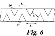
直列接続される燃料電池セルの配列体もしくは積層体30の構成を簡単化するため、従来技術では、図3に示すように、互いに隣り合うセルの間で単一の流れ場プレート31、32を利用する旨、提案されている。例えば、セル34は、これに隣り合うセル35との間でプレート32を共有する。二極プレート32の左側の面(図3で見た左側の)は、セル34のためのカソードとして働き、カソード流れ溝(cathode fluid flow channels)36を備えており、右側の面は、セル35のためのアノードとして働き、アノード流れ溝(anode fluid flow channels)37を備えている。このように、二極流れ場プレート32ではプレートの両面に溝が形成されるから、燃料電池積層体に要求される個々の流れ場プレートの数が低減される。
In order to simplify the configuration of the array or
本発明は、流れ場プレートの構成を更に改善すること、及び、燃料電池積層体の寸法を低減することに関する。 The present invention relates to further improving the configuration of the flow field plate and reducing the size of the fuel cell stack.
本発明では、1つの態様として、燃料電池用の二極流れ場プレートが提供され、この二極流れ場プレートは、導電性の非多孔質シートを含んでいる。導電性非多孔質シートは、該シートの第1の面にパターニングされた第1の流れ溝と、該シートの反対面にパターニングされた第2の流れ溝とを有しており、第1の流れ溝のパターンは、シートの実質領域でみて第2の流れ溝のパターンに直接に重なる部分をもたないように構成されている。 In one aspect, the present invention provides a bipolar flow field plate for a fuel cell, the bipolar flow field plate comprising a conductive non-porous sheet. The conductive non-porous sheet has a first flow groove patterned on the first side of the sheet and a second flow groove patterned on the opposite side of the sheet. The flow groove pattern is configured not to have a portion directly overlapping the second flow groove pattern when viewed in the substantial area of the sheet.
本発明では、もう1つの態様として、燃料電池用の二極流れ場プレートが提供され、この二極流れ場プレートは、導電性の非多孔質シートを含んでいる。導電性非多孔質シートは、該シートの第1の面にパターニングされた第1の流れ溝と、該シートの反対面にパターニングされた第2の流れ溝とを有しており、プレートの有効領域における第1、第2の流れ溝の深さの和は、プレートの全厚よりも大きい。 In another aspect, the present invention provides a bipolar flow field plate for a fuel cell, the bipolar flow field plate comprising a conductive non-porous sheet. The conductive non-porous sheet has a first flow groove patterned on the first side of the sheet and a second flow groove patterned on the opposite side of the sheet, so that the effective plate The sum of the depths of the first and second flow grooves in the region is greater than the total thickness of the plate.
次に、添付図面を参照し、例を挙げて本発明の実施例を説明する。 Embodiments of the present invention will now be described by way of example with reference to the accompanying drawings.
燃料電池の商業的実現にあたって重要な要素の1つは、燃料電池の単位体積あたりでみた供給エネルギー量である。単位体積あたりでより大きな出力を供給する旨の要求が高まっており、これにより、ある程度の改善、例えば、図3及び図4に示された二極流れ場プレート構成がもたらされた。燃料電池積層体の寸法を更に低減するにあたり、本発明者らは、プレート31、32の反対面双方における溝の構成を調和させることにより二極プレートの厚みをかなり低減させることができることを見出した。
One of the important factors in the commercial realization of the fuel cell is the amount of energy supplied per unit volume of the fuel cell. There has been an increasing demand to provide greater power per unit volume, which has led to some improvement, such as the bipolar flow field plate configuration shown in FIGS. In further reducing the dimensions of the fuel cell stack, the inventors have found that the thickness of the bipolar plate can be significantly reduced by harmonizing the groove configuration on both opposite faces of the
図4に示された従来の構成では、二極プレート31、32の厚みは、(プレートの両側面で要求される溝の深さ)+(溝の底部間の厚みであって、プレート構造の一体性を確保するのに充分な厚み)に応じて定められる。このことは図4に示されている。図示のように、二極プレートの厚みTPは、(アノード溝の深さdA)+(カソード溝の深さdC)+(プレートの中間厚みTi)にほぼ等しい。
In the conventional configuration shown in FIG. 4, the thicknesses of the
本発明によれば、プレートの両面におけるアノード流れ溝の構成及びカソード流れ溝の構成は、アノード流れ溝37がカソード流れ溝36に重なるような交差点の数を低減するように調和され、好ましくは該交差点の数をゼロとするように調和される。
According to the present invention, the anode flow groove configuration and the cathode flow groove configuration on both sides of the plate are harmonized to reduce the number of intersections where the
これを達成するため、アノード流れ溝36及びカソード流れ溝37は、図5に示すように交互に配置されて調和された溝となっている。かかる構成の場合、プレートの厚みTPは、(アノード溝の深さdA)+(カソード溝の深さdC)−(溝深さの重なりTO)にほぼ等しい。プレートの各側面における溝の間隔もしくは壁厚み(SA,SC)は、(プレートの他方の側面において間に挟まる溝の幅)+(プレートの反対面で隣り合う各溝の、プレート内部における溝内側の間隔Si)を確保するのに充分な程度、増大させてある。
In order to achieve this, the
図5では、方形状の溝断面(channel profile)が示されており、このような溝断面は各種の化学的エッチング技術、電気化学的加工、研磨加工または他の材料除去プロセスを用い、簡便に形成することができる。図6を参照すると明らかなように、三角形状断面などの他の溝断面を用いても同様な効果が得られる。但し、図6の場合、特定の溝断面となっているから、プレートの各側面における溝間隔SA、SCを、有効な内部溝間隔Siを確保する目的で図5に示されたのと同じ程度に増大させる必要はない。このような例の場合、溝36、37を、プレートの厚み中心よりも大きい深さに形成するため、“中心を超えた位置(past centre)”の材料を除去するプロセスが用いられる。
In FIG. 5, a square channel profile is shown, which can be simplified using various chemical etching techniques, electrochemical machining, polishing or other material removal processes. Can be formed. As apparent from FIG. 6, the same effect can be obtained even if other groove cross sections such as a triangular cross section are used. However, in the case of FIG. 6, since it has a specific groove cross section, the groove intervals S A and S C on each side surface of the plate are shown in FIG. 5 for the purpose of securing an effective internal groove interval S i . Need not be increased to the same extent as In such an example, a process of removing the “past centre” material is used to form the
“中心超え位置”材料除去プロセスを利用できるようにするため、アノード流れ溝及びカソード流れ溝の構成は、実質部分において溝の如何なる重なり合いも回避するように調和され、好ましくは、二極プレート面の有効領域の全てにおいて溝の如何なる重なり合いも回避するように調和される。 In order to be able to take advantage of the “over-center” material removal process, the anode and cathode flow groove configurations are harmonized to avoid any overlap of grooves in a substantial portion, preferably on the bipolar plate surface. It is harmonized to avoid any overlap of grooves in all of the effective area.
典型例となるパターンであって、蛇行し、相互に入り込む掌指状(interdigitated)の櫛状パターンが、図7に概略的に示されている。図7を参照すると、二極流れ場プレート70は、第1の導入マニホールド(first inlet manifold)71を有している。第1の導入マニホールド71は、プレート70の全厚にわたる孔を含んでいることが好ましい。第1の導入マニホールド71は、二極プレートの第1の面に形成された櫛状構造の溝74に通じている。櫛状構造の溝73は、流体を、当該溝に対応する第1の排出マニホールド(first outlet manifold)72に導く。この第1の排出マニホールド72も、プレート70の全厚にわたる孔を含んでいることが好ましい。
A typical example of an interdigitated comb pattern that meanders and interleaves is shown schematically in FIG. Referring to FIG. 7, the bipolar
第2の導入マニホールド75及び第2の排出マニホールド76は、それぞれ、プレート70の全厚にわたる孔を含んでいることが好ましい。二極プレートの反対面では、反対面ゆえ破線で蛇行溝77を示してある。蛇行溝77は、第2の導入マニホールド75及び第2の排出マニホールド76に個別に通じている。使用状態では、ガスが第2の導入マニホールド75を通して供給され、蛇行溝77を通過し、そこから、隣接する多孔質電極に運ばれる(裏張り層が用いられている場合、裏張り層を経由して運ばれる)。利用されなかったガスは、反応生成物とともに、蛇行溝77からカソード排出マニホールド76に排出される。
Each of the second introduction manifold 75 and the
図7に示された溝73、74、77は概略的にしか表示されておらず、相互に入り込む掌指状の櫛構造となっている溝パターンのそれぞれに含まれる“歯”の数、及び、蛇行構造に含まれるターンの数は、かなり多いことが理解されよう。典型例について述べると、プレートの溝密度は、プレート面1センチメートルあたり溝5つである。電極寸法が10cm×10cmとなっている典型的プレートの場合、プレート幅に沿って一方向に横断する部分を25備えた蛇行溝を与えることとなり、相互に入り込む掌指状の一対の櫛構造が、蛇行溝の横断部分の間でプレート幅に沿って延びる歯の当該対応数を与えることとなる。
The
略方形状断面の溝を備えた好ましい本構成の場合、二極流れ場プレートの厚みTPの典型値は0.8mmであり、アノード/カソード溝73、74、77の深さ(dA,dC)は約0.5mmである。従って、溝深さの重なりTOは0.2mmとなる。好ましくは、溝の幅は0.7mmであり、二極プレートの各側面における溝間隔SC、SAは1.1mmであり、内部溝間隔Siは0.2mmである。 For the present preferred configuration with a substantially square cross-sectional groove, the typical value of the bipolar flow field plate thickness T P is 0.8 mm and the depth (d A , d C ) is about 0.5 mm. Therefore, the groove depth overlap T O is 0.2 mm. Preferably, the groove width is 0.7 mm, the groove spacings S C and S A on each side of the bipolar plate are 1.1 mm, and the internal groove spacing S i is 0.2 mm.
好ましい例において、プレート厚みTPは0.3mmから1.5mmまでの範囲にあり、溝深さdA、dCは0.2mmから1.1mmまでの範囲にあり、溝深さの重なりは0.1mmから0.4mmの範囲にあり、溝間隔SC、SAは0.5mmから1.5mmまでの範囲にあり、内部溝間隔は0.05mmから0.35mmまでの範囲にある。 In a preferred example, the plate thickness T P is in the range from 0.3 mm to 1.5 mm, the groove depths d A and d C are in the range from 0.2 mm to 1.1 mm, and the groove depth overlap is It is in the range of 0.1 mm to 0.4 mm, the groove intervals S C and S A are in the range of 0.5 mm to 1.5 mm, and the internal groove interval is in the range of 0.05 mm to 0.35 mm.
図示された好ましい構成では、アノード溝73及びカソード溝77の両者は、深さが等しく、かつ、その深さがプレート厚みの1/2よりも大きくなるように形成されている。しかし、溝の深さは等しくなくてもよく、この場合、二極プレートの一方の側面における材料除去プロセスは、他方の側面における材料除去プロセスよりも深く行うことになることが理解されよう。
In the preferred configuration shown, both the
更に、アノード溝とカソード溝との相対的な幅も変更できることも理解されよう。アノード溝とカソード溝との相対的な幅及び深さを変更すると、アノード溝 対 カソード溝の相対的体積を変更することが可能となり、この相対的体積の変更は、例えば、さまざまな流体について適正な流れを維持するのに有効となり得る。 It will also be appreciated that the relative widths of the anode and cathode grooves can be varied. Changing the relative width and depth of the anode and cathode grooves can change the relative volume of the anode and cathode grooves, which can be appropriate for various fluids, for example. Can be effective in maintaining a smooth flow.
二極流れ場プレートにおける他の溝パターンとしては、かなりの数の溝パターンが用いられ得る。図10には、このような他の溝パターンが2つ示されている。図10aの場合、溝パターン100は、第1の(例えばアノードの)溝パターンを含んでいる。第1の溝パターンは4つの櫛状構造101を含んでおり、これらの櫛状構造に含まれている“歯”は、隣接する多孔質電極を通して為される拡散により、それぞれの中間溝部分102に通じることになる。従って、マニホールド103から溝101、102を経由してマニホールド104に至る流体の流れを維持することができる。
A number of groove patterns can be used as other groove patterns in the bipolar flow field plate. FIG. 10 shows two such other groove patterns. In the case of FIG. 10a, the
第2の(例えばカソードの)溝パターンが、二極流れ場プレートの有効領域(但し、二極流れ場プレートの反対面上ではない)を横切って延びている。第2の溝パターンは、一対の溝105、106を含んでおり、これら溝105、106のそれぞれは、分岐して再合流する連続的な溝である。かような溝105、106により、マニホールド107、108の間で流体の流れを維持することが可能となる。
A second (eg, cathode) groove pattern extends across the effective area of the bipolar flow field plate (but not on the opposite side of the bipolar flow field plate). The second groove pattern includes a pair of
今までアノード及びカソードに言及したことについては逆にすることができ、この場合、櫛状パターンがカソード溝に用いられ、蛇行パターンがアノード溝に用いられることが理解されよう。 It will be appreciated that what has been said so far to the anode and cathode can be reversed, in which case a comb-like pattern is used for the cathode groove and a serpentine pattern is used for the anode groove.
図10bは、図10aに示された溝パターンに対する他の溝パターン110を示している。この溝パターン110では、櫛状パターンの溝101に備えられた中間溝部分102について長さを異ならせることが必要とされており、分れ、分岐して再合流する連続的な溝105がパターニングされている。
FIG. 10b shows another
概略的に述べるが、今まで説明された実施例を考慮すると、次の組み合わせ態様、すなわち、二極流れ場プレートの一方の側面に、分岐して再合流する連続的な流れ溝を備えるとともに、二極流れ場プレートの他方の側面に、相互に入り込む掌指状の“櫛”状流れ溝を備え、これらの流れ溝の両方とも深さがプレート厚みの1/2よりも大きいような組み合わせ態様があり得る。かかる構成によれば、どんなプレート厚みが与えられた場合でも、それぞれの流体流路内で大きな流れ断面積を与えることができる。従って、与えられたプレート厚みについて、上述の流路内でどんな圧力降下量が規定されても、容量でみた処理能力を改善することができる。 In summary, in view of the embodiment described so far, the following combination is provided: a continuous flow groove that branches and rejoins on one side of the bipolar flow field plate; A combination mode in which the other side surface of the bipolar flow field plate has finger-like “comb” -like flow grooves that penetrate each other, and both of these flow grooves have a depth greater than ½ of the plate thickness. There can be. According to such a configuration, regardless of the plate thickness, a large flow cross-sectional area can be provided in each fluid flow path. Therefore, for any given plate thickness, whatever the amount of pressure drop is defined in the flow path described above, the capacity in terms of capacity can be improved.
図7、図10a及び図10bを参照すると、アノード溝構造のうち何れかの部分が、カソード溝構造のうち何れかの部分に重なり合うような交差点は、1つもないことがわかるであろう。この構成では、二極流れ場プレートの各側面における溝の面積を最大化することと、プレート厚みを最小化することとの間で、効果的なバランスが示されている。他のアノード溝及びカソード溝の幾何学的パターンとしては、この基準をさまざまな程度に合わせた多くの幾何学的パターンが用いられ得る。図10aの実施例及び図10bの実施例の場合、(正確には流れ場プレートの面から)隣接する多孔質電極を通して為される拡散により、(例えば、溝部分102、103間における)溝の“不連続部分”を超えて流れる流体流れが生じることになる。
Referring to FIGS. 7, 10a and 10b, it can be seen that there is no single intersection where any portion of the anode groove structure overlaps any portion of the cathode groove structure. This configuration shows an effective balance between maximizing the groove area on each side of the bipolar flow field plate and minimizing the plate thickness. As other geometric patterns of the anode groove and the cathode groove, many geometric patterns adapted to various standards can be used. In the embodiment of FIG. 10a and the embodiment of FIG. 10b, the diffusion of the groove (e.g. between the
図8を参照すると、交差点は、適切には、例えば、櫛状構造に含まれているそれぞれの歯に導かれている溝の位置など、シートの有効領域の外側に配置できることが認識されよう。図示では、このことは、溝73が交差溝77に重なる領域80で、溝73の深さdAを断続的に減らすことにより、行われる。この配置の場合、溝深さが一時的に減らされたことを補うため、領域80で溝73の幅を局所的に増大させ、溝の流れ容量を維持することが好ましいかもしれない。
Referring to FIG. 8, it will be appreciated that the intersection can suitably be located outside the effective area of the sheet, for example, the location of a groove leading to each tooth included in the comb structure. In the illustration, this is done by intermittently reducing the depth d A of the
この方法のほかに、アノード流れ溝がカソード流れ溝(正確には交差方向のカソード流れ溝)に重ならねばならず、隣接する電極を通して為される拡散が充分に良好であるとはいえないような交差点を制限できるような他の方法も存在する。 In addition to this method, the anode flow groove must overlap the cathode flow groove (exactly the cross-direction cathode flow groove), so that the diffusion done through the adjacent electrodes is not good enough. There are other ways to limit the number of intersections.
流れ場プレート及びその流れ場プレートに形成される溝に隣接する多孔質電極は、適切には、機械加工、研磨加工またはエンボス加工された面で製造することができ、この多孔質電極では、多孔質電極に形成される局所的な溝の小部分を利用することにより、二極プレートの不連続な流れ溝を超えて流れる流体流路を付与できると認識されている。 The flow field plate and the porous electrode adjacent to the groove formed in the flow field plate can suitably be manufactured with a machined, polished or embossed surface, in which the porous electrode It has been recognized that the use of a small portion of a local groove formed in a porous electrode can provide a fluid flow path that flows beyond the discontinuous flow groove of the bipolar plate.
図9を参照すると、二極流れ場プレート91はアノード溝94を含んでおり、アノード溝94は(図示のように図面を横切って延び)、領域95に不連続部分を備えている。この領域95の真下では、カソード溝96が交差方向に延びている。矢印で示された流体の流れに連続性を与えるため、小さなバイパス溝97がアノード92の表面に形成されており、このバイパス溝97は、二極流れ場プレート91の不連続な溝94の端部に合わさる。従って、バイパス溝97により、交差溝96の何れかの側にある溝94の端部の間で、二極プレート91の面の外側に流体を通じさせることが可能となる。
Referring to FIG. 9, the bipolar
カソード溝が、その下側にあるアノード溝に交差しなければならない場合も、同様な構造を採用することができる。このように、バイパス溝97は、アノードの表面に形成するのと同じ様に、カソードの表面に形成することができる。
A similar structure can be employed when the cathode groove must intersect the underlying anode groove. Thus, the
好ましくは、多孔質アノード92または多孔質カソードに形成されるバイパス溝97は、交差溝96を覆う領域95を横切るのに必要なだけの長さとなっている。好ましい実施例では、バイパス溝の長さは0.1mmから2.0mmまでの範囲にある。バイパス溝の幅及び深さは、好ましくは、二極流れ場プレートの溝であって該バイパス溝が通じることになる溝の幅及び深さに対応する。好ましくは、バイパス溝は、粒子衝突などによる周知の研磨除去法を用いることにより、多孔質炭素電極に形成される。
Preferably, the
上述のように協働するアノード及びカソード流れ溝36、37について述べる。(図3に示されているように)同一構成の複数の二極プレート32を積層体として用いる場合、膜−電極組立体(11〜13)の両側にあって向かい合うアノード流れ溝及びカソード流れ溝は、互いに偏位した位置となるであろう。もし、これらの溝を互いに重ねて配置したい場合には、隣り合う二極プレートの流れ溝(積層体の積層方向でみて交互関係となる)を、横方向に互いに偏位させて配置し、これにより、アノード流れ溝及びカソード流れ溝の位置を合わせてもよい。
The anode and
反対性のガス蒸気を必要とする燃料電池装置について本発明の例を説明したが、この方法論は、“ゼロ−ギャップ”セル内で電解生成されるガスに、膜(membrane)または隔膜(diaphragm)による分離を適用した合成セルにも応用することができる。 Although an example of the invention has been described for a fuel cell device that requires an opposite gas vapor, this methodology can be applied to the gas produced electrolytically in a “zero-gap” cell by a membrane or diaphragm. The present invention can also be applied to a synthesis cell to which separation by is applied.
本発明の他の実施例は、添付された特許請求の範囲内に在る。 Other embodiments of the invention are within the scope of the appended claims.
Claims (9)
導電性非多孔質シートは、第1の面にパターニングされた第1の流れ溝と、前記第1の面の反対面にパターニングされた第2の流れ溝とを有しており、
プレートの有効領域における前記第1及び第2の流れ溝の深さの和は、プレートの全厚よりも大きく、
少なくとも前記第1の流れ溝は、前記第1の面において不連続となっており、
前記多孔質電極は、バイパス溝を含み、少なくとも前記第1の面に隣接して装着されており、
前記バイパス溝は、該不連続な流れ溝に合わさることによって、該不連続な流れ溝の間で流体を通じさせる、
二極流れ場プレート。A bipolar flow field plate for a fuel cell, comprising a conductive non-porous sheet and a porous electrode ,
The conductive non-porous sheet has a first flow groove patterned on the first surface and a second flow groove patterned on the opposite surface of the first surface .
The sum of the depth of the first and second flow grooves in the effective area of the plate is much larger than the total thickness of the plate,
At least the first flow groove is discontinuous in the first surface;
The porous electrode includes a bypass groove and is mounted adjacent to at least the first surface;
The bypass grooves allow fluid to pass between the discontinuous flow grooves by mating with the discontinuous flow grooves;
Bipolar flow field plate.
導電性非多孔質シートは、第1の面にパターニングされた第1の流れ溝と、前記第1の面の反対面にパターニングされた第2の流れ溝とを有しており、The conductive non-porous sheet has a first flow groove patterned on the first surface and a second flow groove patterned on the opposite surface of the first surface.
プレートの有効領域における第1、第2の流れ溝の深さの和は、プレートの全厚よりも大きく、The sum of the depths of the first and second flow grooves in the effective area of the plate is greater than the total thickness of the plate,
少なくとも前記第1の流れ溝は、前記第1の面において不連続となっており、At least the first flow groove is discontinuous in the first surface;
前記多孔質電極は、少なくとも前記第1の面に隣接して装着されており、The porous electrode is mounted adjacent to at least the first surface;
この多孔質電極を通して為される拡散により、該不連続な流れ溝の間で流体を通じさせる、Fluid is passed between the discontinuous flow grooves by diffusion performed through the porous electrode;
二極流れ場プレート。Bipolar flow field plate.
前記第1の流れ溝の深さ及び前記第2の流れ溝の深さの両方が、それぞれ、プレート厚みの1/2よりも大きい、
二極流れ場プレート。A bipolar flow field plate according to claim 1 or 2 ,
Both the depth of the first depth and the second flow grooves of flow grooves, respectively, greater than 1/2 of the plate thickness,
Bipolar flow field plate.
溝深さは、プレートの有効領域全体にわたって実質的に均一である、
二極流れ場プレート。A bipolar flow field plate according to any of claims 1 to 3 ,
The groove depth is substantially uniform throughout the effective area of the plate,
Bipolar flow field plate.
前記バイパス溝は、二極流れ場プレートの反対面に形成された第2の流れ溝が第1の面の溝パターンに交差する部分に重なるように配置されている、
二極流れ場プレート。A bipolar flow field plate according to claim 1 , comprising:
The bypass groove is disposed such that a second flow groove formed on the opposite surface of the bipolar flow field plate overlaps a portion intersecting the groove pattern of the first surface.
Bipolar flow field plate.
第1の流れ溝のパターンは、シートの実質領域でみて第2の流れ溝のパターンに直接に重なる部分をもたないように構成されている、
二極流れ場プレート。A bipolar flow field plate according to claim 1 or 2 ,
The first flow groove pattern is configured not to have a portion that directly overlaps the second flow groove pattern when viewed in the substantial area of the sheet.
Bipolar flow field plate.
第1の流れ溝のパターンは、シートの領域全体でみて第2の流れ溝のパターンに直接に重なる部分をもたないように構成されている、
二極流れ場プレート。A bipolar flow field plate according to claim 6,
The first flow groove pattern is configured not to have a portion that directly overlaps the second flow groove pattern when viewed in the entire area of the sheet.
Bipolar flow field plate.
プレートの反対面双方に形成された溝の間の内部溝間隔は、0.1mm以上である、
二極流れ場プレート。A bipolar flow field plate according to claim 1 or 2 ,
The internal groove interval between the grooves formed on both opposite surfaces of the plate is 0.1 mm or more.
Bipolar flow field plate.
前記バイパス溝の長さは、0.1mmから2.0mmまでの範囲にある、
二極流れ場プレート。A bipolar flow field plate according to claim 1 , comprising:
The length of the bypass groove is in a range from 0.1 mm to 2.0 mm.
Bipolar flow field plate.
Applications Claiming Priority (3)
| Application Number | Priority Date | Filing Date | Title |
|---|---|---|---|
| GB0126688A GB2382455B (en) | 2001-11-07 | 2001-11-07 | Fuel cell fluid flow field plates |
| GB0126688.1 | 2001-11-07 | ||
| PCT/GB2002/004483 WO2003041199A2 (en) | 2001-11-07 | 2002-10-03 | Fuel cell fluid flow field plates |
Publications (3)
| Publication Number | Publication Date |
|---|---|
| JP2005509260A JP2005509260A (en) | 2005-04-07 |
| JP2005509260A5 JP2005509260A5 (en) | 2006-01-05 |
| JP4700910B2 true JP4700910B2 (en) | 2011-06-15 |
Family
ID=9925290
Family Applications (1)
| Application Number | Title | Priority Date | Filing Date |
|---|---|---|---|
| JP2003543127A Expired - Fee Related JP4700910B2 (en) | 2001-11-07 | 2002-10-03 | Fuel cell flow field plate |
Country Status (11)
| Country | Link |
|---|---|
| US (1) | US8304139B2 (en) |
| EP (1) | EP1442491B1 (en) |
| JP (1) | JP4700910B2 (en) |
| BR (1) | BR0206313A (en) |
| CA (1) | CA2471122C (en) |
| GB (1) | GB2382455B (en) |
| MX (1) | MXPA04004279A (en) |
| NO (1) | NO333667B1 (en) |
| RU (1) | RU2302689C2 (en) |
| WO (1) | WO2003041199A2 (en) |
| ZA (1) | ZA200304912B (en) |
Families Citing this family (36)
| Publication number | Priority date | Publication date | Assignee | Title |
|---|---|---|---|---|
| GB2412784B (en) * | 2002-01-18 | 2006-08-23 | Intelligent Energy Ltd | Fuel cell oxygen removal and pre-conditioning system |
| GB2390738B (en) * | 2002-07-09 | 2005-05-11 | Intelligent Energy Ltd | Fuel cell direct water injection |
| GB2401986B (en) * | 2003-05-17 | 2005-11-09 | Intelligent Energy Ltd | Improvements in fuel utilisation in electrochemical fuel cells |
| GB2409763B (en) | 2003-12-31 | 2007-01-17 | Intelligent Energy Ltd | Water management in fuel cells |
| GB2413002B (en) * | 2004-04-08 | 2006-12-06 | Intelligent Energy Ltd | Fuel cell gas distribution |
| WO2005117177A1 (en) * | 2004-05-31 | 2005-12-08 | Toyota Jidosha Kabushiki Kaisha | Fuel cell |
| KR100647666B1 (en) * | 2004-11-29 | 2006-11-23 | 삼성에스디아이 주식회사 | Bipolar plate and direct liquid feed fuel cell stack |
| GB2422716B (en) * | 2005-01-26 | 2007-08-22 | Intelligent Energy Ltd | Multi-layer fuel cell diffuser |
| KR100627373B1 (en) * | 2005-04-08 | 2006-09-22 | 삼성에스디아이 주식회사 | Stack for fuel cell |
| KR100722093B1 (en) * | 2005-10-19 | 2007-05-25 | 삼성에스디아이 주식회사 | Membrane-electrode assembly for fuel cell, method for manufacturing the same, and fuel cell system comprising the same |
| GB2434845B (en) * | 2006-02-01 | 2010-10-13 | Intelligent Energy Ltd | Variable compressibility gaskets |
| CN101346842B (en) * | 2006-06-21 | 2012-04-18 | 松下电器产业株式会社 | Fuel cell |
| DE102007062033A1 (en) * | 2007-12-21 | 2009-06-25 | Robert Bosch Gmbh | Electro-chemical fuel cell, has current flow plate with micro-reaction chamber arranged in external surface and at flow channel, and catalyst arranged in part of chamber such that catalyst contacts with membrane element and reactant |
| US8884237B2 (en) * | 2008-02-12 | 2014-11-11 | Nova Scientific, Inc. | Neutron detection |
| US8986905B2 (en) * | 2008-11-11 | 2015-03-24 | Bloom Energy Corporation | Fuel cell interconnect |
| WO2010100872A1 (en) * | 2009-03-04 | 2010-09-10 | パナソニック株式会社 | Separator for fuel cell, and fuel cell comprising same |
| US8568941B2 (en) | 2009-03-04 | 2013-10-29 | Panasonic Corporation | Fuel cell separator and fuel cell including same |
| US20110014537A1 (en) * | 2009-07-16 | 2011-01-20 | Ford Motor Company | Fuel cell |
| US8916313B2 (en) * | 2009-07-16 | 2014-12-23 | Ford Motor Company | Fuel cell |
| CN102201583A (en) * | 2011-04-22 | 2011-09-28 | 沈阳建筑大学 | Proton exchange membrane fuel cell flow field structure |
| US9444105B2 (en) | 2011-11-04 | 2016-09-13 | Fluidic, Inc. | Immersible gaseous oxidant cathode for electrochemical cell system |
| US20150263358A1 (en) * | 2011-12-20 | 2015-09-17 | United Technologies Corporation | Flow battery with mixed flow |
| WO2017073530A1 (en) * | 2015-10-28 | 2017-05-04 | 日本特殊陶業株式会社 | Interconnector-electrochemical reaction unit cell composite body, electrochemical reaction cell stack, and production method for interconnector-electrochemical reaction unit cell composite body |
| TWI624989B (en) | 2016-12-14 | 2018-05-21 | 財團法人工業技術研究院 | Bipolar plate, fuel cell and fuel cell stack |
| CN106602100B (en) * | 2017-01-04 | 2023-05-12 | 沈阳建筑大学 | Novel fuel cell flow field plate |
| WO2018183047A1 (en) * | 2017-03-29 | 2018-10-04 | Ballard Power Systems Inc. | Flow field plate for an electrochemical fuel cell |
| WO2019046724A1 (en) | 2017-09-01 | 2019-03-07 | Itn Energy Systems, Inc. | Segmented frames for redox flow batteries |
| US10497948B2 (en) * | 2017-09-25 | 2019-12-03 | GM Global Technology Operations LLC | Fuel cell stack with asymmetrical bipolar plates |
| WO2019133702A1 (en) | 2017-12-29 | 2019-07-04 | Staq Energy, Inc. | Long life sealed alkaline secondary batteries |
| MA53343A (en) | 2018-07-27 | 2022-03-23 | Form Energy Inc | NEGATIVE ELECTRODES FOR ELECTROCHEMICAL CELLS |
| US11056698B2 (en) | 2018-08-02 | 2021-07-06 | Raytheon Technologies Corporation | Redox flow battery with electrolyte balancing and compatibility enabling features |
| CN109509896B (en) * | 2018-12-11 | 2020-10-02 | 中国科学院大连化学物理研究所 | Flow field structure for improving effective area of flow field of wavy flow channel of bipolar plate of fuel cell |
| DE102020114066A1 (en) | 2020-05-26 | 2021-12-02 | Audi Aktiengesellschaft | Bipolar plate |
| US11271226B1 (en) | 2020-12-11 | 2022-03-08 | Raytheon Technologies Corporation | Redox flow battery with improved efficiency |
| CN114824347A (en) * | 2022-03-31 | 2022-07-29 | 潍柴巴拉德氢能科技有限公司 | Bipolar plate and fuel cell |
| CN115642270B (en) * | 2022-12-23 | 2023-04-07 | 南方科技大学 | Flow field plate of flow battery and flow battery |
Citations (9)
| Publication number | Priority date | Publication date | Assignee | Title |
|---|---|---|---|---|
| JPS5912572A (en) * | 1982-06-28 | 1984-01-23 | Sanyo Electric Co Ltd | Fuel cell |
| JPS59217955A (en) * | 1983-05-25 | 1984-12-08 | Mitsubishi Electric Corp | Phosphoric-acid-type fuel cell |
| JPH02278667A (en) * | 1989-04-18 | 1990-11-14 | Fuji Electric Co Ltd | Repair method for fuel cell stack |
| JPH04306568A (en) * | 1990-08-27 | 1992-10-29 | Gebr Sulzer Ag | Method for dissipating heat from fuel cell and temperature balancing member |
| JPH09504901A (en) * | 1993-09-24 | 1997-05-13 | バラード パワー システムズ インコーポレイティド | Fuel cell assembly with integral selective oxidizer |
| JPH09259904A (en) * | 1996-03-19 | 1997-10-03 | Ishikawajima Harima Heavy Ind Co Ltd | Fuel battery |
| US5776624A (en) * | 1996-12-23 | 1998-07-07 | General Motors Corporation | Brazed bipolar plates for PEM fuel cells |
| JP2000251907A (en) * | 1999-02-24 | 2000-09-14 | Sanyo Electric Co Ltd | Solid polymer fuel cell |
| WO2001004982A1 (en) * | 1999-07-08 | 2001-01-18 | Loughborough University Innovations Limited | Flow field plates |
Family Cites Families (25)
| Publication number | Priority date | Publication date | Assignee | Title |
|---|---|---|---|---|
| GB959557A (en) | 1960-04-01 | 1964-06-03 | Nat Res Dev | Improvements in fuel cells |
| GB1151373A (en) | 1965-05-18 | 1969-05-07 | Energy Conversion Ltd | Improvements in and relating to Electrochemical Cell Arrangements |
| US4988583A (en) * | 1989-08-30 | 1991-01-29 | Her Majesty The Queen As Represented By The Minister Of National Defence Of Her Majesty's Canadian Government | Novel fuel cell fluid flow field plate |
| US5108849A (en) * | 1989-08-30 | 1992-04-28 | Her Majesty The Queen In Right Of Canada, As Represented By The Minister Of National Defence In Her Britannic Majesty's Government Of The United Kingdom Of Great Britain And Northern Ireland | Fuel cell fluid flow field plate |
| US5300370A (en) * | 1992-11-13 | 1994-04-05 | Ballard Power Systems Inc. | Laminated fluid flow field assembly for electrochemical fuel cells |
| US5527363A (en) * | 1993-12-10 | 1996-06-18 | Ballard Power Systems Inc. | Method of fabricating an embossed fluid flow field plate |
| RU2174728C2 (en) * | 1994-10-12 | 2001-10-10 | Х Пауэр Корпорейшн | Fuel cell using integrated plate technology for liquid-distribution |
| JPH08287928A (en) | 1995-04-17 | 1996-11-01 | Sanyo Electric Co Ltd | Flat fuel cell and its manufacture |
| US6071635A (en) * | 1998-04-03 | 2000-06-06 | Plug Power, L.L.C. | Easily-formable fuel cell assembly fluid flow plate having conductivity and increased non-conductive material |
| US6207312B1 (en) * | 1998-09-18 | 2001-03-27 | Energy Partners, L.C. | Self-humidifying fuel cell |
| US6322919B1 (en) | 1999-08-16 | 2001-11-27 | Alliedsignal Inc. | Fuel cell and bipolar plate for use with same |
| US6296964B1 (en) * | 1999-12-23 | 2001-10-02 | The Regents Of The University Of California | Enhanced methanol utilization in direct methanol fuel cell |
| US7001688B2 (en) * | 2000-09-18 | 2006-02-21 | Mitsubishi Heavy Industries, Ltd. | Solid polymer type fuel battery |
| US6544681B2 (en) | 2000-12-26 | 2003-04-08 | Ballard Power Systems, Inc. | Corrugated flow field plate assembly for a fuel cell |
| US6503653B2 (en) * | 2001-02-23 | 2003-01-07 | General Motors Corporation | Stamped bipolar plate for PEM fuel cell stack |
| GB2412784B (en) * | 2002-01-18 | 2006-08-23 | Intelligent Energy Ltd | Fuel cell oxygen removal and pre-conditioning system |
| GB2387959C (en) * | 2002-03-28 | 2005-02-09 | Intelligent Energy Ltd | Fuel cell compression assembly |
| GB2390738B (en) * | 2002-07-09 | 2005-05-11 | Intelligent Energy Ltd | Fuel cell direct water injection |
| GB2396688B (en) * | 2002-11-22 | 2006-06-28 | Intelligent Energy Ltd | Thermal energy management in electrochemical fuel cells |
| GB2401986B (en) * | 2003-05-17 | 2005-11-09 | Intelligent Energy Ltd | Improvements in fuel utilisation in electrochemical fuel cells |
| GB2409763B (en) * | 2003-12-31 | 2007-01-17 | Intelligent Energy Ltd | Water management in fuel cells |
| GB2413002B (en) * | 2004-04-08 | 2006-12-06 | Intelligent Energy Ltd | Fuel cell gas distribution |
| GB2422716B (en) * | 2005-01-26 | 2007-08-22 | Intelligent Energy Ltd | Multi-layer fuel cell diffuser |
| GB2422717B (en) * | 2005-02-01 | 2007-11-14 | Intelligent Energy Ltd | Detachable fuel cell power unit for vehicle applications |
| GB2434845B (en) * | 2006-02-01 | 2010-10-13 | Intelligent Energy Ltd | Variable compressibility gaskets |
-
2001
- 2001-11-07 GB GB0126688A patent/GB2382455B/en not_active Expired - Lifetime
-
2002
- 2002-10-03 JP JP2003543127A patent/JP4700910B2/en not_active Expired - Fee Related
- 2002-10-03 CA CA2471122A patent/CA2471122C/en not_active Expired - Fee Related
- 2002-10-03 MX MXPA04004279A patent/MXPA04004279A/en active IP Right Grant
- 2002-10-03 RU RU2004117094/09A patent/RU2302689C2/en not_active IP Right Cessation
- 2002-10-03 EP EP02765083.7A patent/EP1442491B1/en not_active Expired - Lifetime
- 2002-10-03 WO PCT/GB2002/004483 patent/WO2003041199A2/en active Application Filing
- 2002-10-03 US US10/494,628 patent/US8304139B2/en active Active
- 2002-10-03 BR BR0206313-1A patent/BR0206313A/en not_active Application Discontinuation
-
2003
- 2003-06-24 ZA ZA200304912A patent/ZA200304912B/en unknown
- 2003-07-07 NO NO20033090A patent/NO333667B1/en not_active IP Right Cessation
Patent Citations (9)
| Publication number | Priority date | Publication date | Assignee | Title |
|---|---|---|---|---|
| JPS5912572A (en) * | 1982-06-28 | 1984-01-23 | Sanyo Electric Co Ltd | Fuel cell |
| JPS59217955A (en) * | 1983-05-25 | 1984-12-08 | Mitsubishi Electric Corp | Phosphoric-acid-type fuel cell |
| JPH02278667A (en) * | 1989-04-18 | 1990-11-14 | Fuji Electric Co Ltd | Repair method for fuel cell stack |
| JPH04306568A (en) * | 1990-08-27 | 1992-10-29 | Gebr Sulzer Ag | Method for dissipating heat from fuel cell and temperature balancing member |
| JPH09504901A (en) * | 1993-09-24 | 1997-05-13 | バラード パワー システムズ インコーポレイティド | Fuel cell assembly with integral selective oxidizer |
| JPH09259904A (en) * | 1996-03-19 | 1997-10-03 | Ishikawajima Harima Heavy Ind Co Ltd | Fuel battery |
| US5776624A (en) * | 1996-12-23 | 1998-07-07 | General Motors Corporation | Brazed bipolar plates for PEM fuel cells |
| JP2000251907A (en) * | 1999-02-24 | 2000-09-14 | Sanyo Electric Co Ltd | Solid polymer fuel cell |
| WO2001004982A1 (en) * | 1999-07-08 | 2001-01-18 | Loughborough University Innovations Limited | Flow field plates |
Also Published As
| Publication number | Publication date |
|---|---|
| US20050048351A1 (en) | 2005-03-03 |
| WO2003041199A3 (en) | 2003-11-27 |
| GB2382455A (en) | 2003-05-28 |
| EP1442491A2 (en) | 2004-08-04 |
| NO20033090L (en) | 2003-09-02 |
| GB2382455B (en) | 2004-10-13 |
| WO2003041199A2 (en) | 2003-05-15 |
| US8304139B2 (en) | 2012-11-06 |
| ZA200304912B (en) | 2004-09-27 |
| CA2471122C (en) | 2010-11-30 |
| EP1442491B1 (en) | 2017-08-16 |
| NO20033090D0 (en) | 2003-07-07 |
| JP2005509260A (en) | 2005-04-07 |
| RU2302689C2 (en) | 2007-07-10 |
| MXPA04004279A (en) | 2005-05-16 |
| CA2471122A1 (en) | 2003-05-15 |
| RU2004117094A (en) | 2005-11-20 |
| BR0206313A (en) | 2004-02-10 |
| NO333667B1 (en) | 2013-08-05 |
| GB0126688D0 (en) | 2002-01-02 |
Similar Documents
| Publication | Publication Date | Title |
|---|---|---|
| JP4700910B2 (en) | Fuel cell flow field plate | |
| TWI411155B (en) | Fuel cell fluid distribution plates | |
| WO2010082589A1 (en) | Fuel cell stack | |
| JP2002260710A (en) | Solid polymer cell assembly, fuel cell stack and supply method of reactive gas for fuel cell | |
| EP1639664A1 (en) | Flow field plate geometries | |
| WO2004114446A1 (en) | Flow field plate geometries | |
| JP3459300B2 (en) | Polymer electrolyte fuel cell | |
| JP2004079245A (en) | Fuel cell | |
| JP4936663B2 (en) | Fuel cell direct water injection | |
| JP5449838B2 (en) | Fuel cell stack | |
| US20060003220A1 (en) | Fuel cell | |
| JPH0437550B2 (en) | ||
| WO2009154082A1 (en) | Fuel cell stack | |
| EP1627443B1 (en) | Improvements in fuel utilisation in electrochemical fuel cells | |
| US6203676B1 (en) | Ionic conduction device | |
| JP2004047214A (en) | Fuel cell | |
| JP2001250568A (en) | Collector panel for solid polymer fuel cell | |
| JP4572252B2 (en) | Fuel cell stack | |
| JP2007149358A (en) | Separator for fuel cell | |
| WO2019207811A1 (en) | Fuel cell gas feed diffusion layer, fuel cell separator, and fuel cell stack | |
| JPH081806B2 (en) | Fuel cell separator and fuel cell using the same | |
| JPS5830074A (en) | Fuel cell | |
| US8916313B2 (en) | Fuel cell | |
| JP2008123901A (en) | Fuel cell | |
| GB2403061A (en) | Flow field plate geometries |
Legal Events
| Date | Code | Title | Description |
|---|---|---|---|
| A521 | Request for written amendment filed |
Free format text: JAPANESE INTERMEDIATE CODE: A523 Effective date: 20050824 |
|
| A621 | Written request for application examination |
Free format text: JAPANESE INTERMEDIATE CODE: A621 Effective date: 20050824 |
|
| RD04 | Notification of resignation of power of attorney |
Free format text: JAPANESE INTERMEDIATE CODE: A7424 Effective date: 20090225 |
|
| A131 | Notification of reasons for refusal |
Free format text: JAPANESE INTERMEDIATE CODE: A131 Effective date: 20090624 |
|
| A601 | Written request for extension of time |
Free format text: JAPANESE INTERMEDIATE CODE: A601 Effective date: 20090907 |
|
| A602 | Written permission of extension of time |
Free format text: JAPANESE INTERMEDIATE CODE: A602 Effective date: 20090914 |
|
| A521 | Request for written amendment filed |
Free format text: JAPANESE INTERMEDIATE CODE: A523 Effective date: 20091021 |
|
| A131 | Notification of reasons for refusal |
Free format text: JAPANESE INTERMEDIATE CODE: A131 Effective date: 20100414 |
|
| A521 | Request for written amendment filed |
Free format text: JAPANESE INTERMEDIATE CODE: A523 Effective date: 20100702 |
|
| A01 | Written decision to grant a patent or to grant a registration (utility model) |
Free format text: JAPANESE INTERMEDIATE CODE: A01 Effective date: 20110216 |
|
| A61 | First payment of annual fees (during grant procedure) |
Free format text: JAPANESE INTERMEDIATE CODE: A61 Effective date: 20110307 |
|
| FPAY | Renewal fee payment (event date is renewal date of database) |
Free format text: PAYMENT UNTIL: 20140311 Year of fee payment: 3 |
|
| S531 | Written request for registration of change of domicile |
Free format text: JAPANESE INTERMEDIATE CODE: R313531 |
|
| FPAY | Renewal fee payment (event date is renewal date of database) |
Free format text: PAYMENT UNTIL: 20140311 Year of fee payment: 3 |
|
| R350 | Written notification of registration of transfer |
Free format text: JAPANESE INTERMEDIATE CODE: R350 |
|
| R250 | Receipt of annual fees |
Free format text: JAPANESE INTERMEDIATE CODE: R250 |
|
| R250 | Receipt of annual fees |
Free format text: JAPANESE INTERMEDIATE CODE: R250 |
|
| R250 | Receipt of annual fees |
Free format text: JAPANESE INTERMEDIATE CODE: R250 |
|
| LAPS | Cancellation because of no payment of annual fees |