JP6876197B2 - Fuel cell gas supply diffusion layer, fuel cell separator and fuel cell cell stack - Google Patents
Fuel cell gas supply diffusion layer, fuel cell separator and fuel cell cell stack Download PDFInfo
- Publication number
- JP6876197B2 JP6876197B2 JP2020515996A JP2020515996A JP6876197B2 JP 6876197 B2 JP6876197 B2 JP 6876197B2 JP 2020515996 A JP2020515996 A JP 2020515996A JP 2020515996 A JP2020515996 A JP 2020515996A JP 6876197 B2 JP6876197 B2 JP 6876197B2
- Authority
- JP
- Japan
- Prior art keywords
- fuel cell
- gas
- diffusion layer
- flow path
- gas supply
- Prior art date
- Legal status (The legal status is an assumption and is not a legal conclusion. Google has not performed a legal analysis and makes no representation as to the accuracy of the status listed.)
- Active
Links
- 239000000446 fuel Substances 0.000 title claims description 445
- 238000009792 diffusion process Methods 0.000 title claims description 273
- 239000012528 membrane Substances 0.000 claims description 69
- 230000015572 biosynthetic process Effects 0.000 claims description 27
- 239000007789 gas Substances 0.000 description 618
- 230000004048 modification Effects 0.000 description 59
- 238000012986 modification Methods 0.000 description 59
- 229910052751 metal Inorganic materials 0.000 description 51
- 239000002184 metal Substances 0.000 description 51
- XLYOFNOQVPJJNP-UHFFFAOYSA-N water Substances O XLYOFNOQVPJJNP-UHFFFAOYSA-N 0.000 description 31
- 239000000498 cooling water Substances 0.000 description 30
- 238000010248 power generation Methods 0.000 description 24
- 238000005755 formation reaction Methods 0.000 description 21
- 238000010586 diagram Methods 0.000 description 20
- 229910001868 water Inorganic materials 0.000 description 20
- 238000005260 corrosion Methods 0.000 description 16
- 230000007797 corrosion Effects 0.000 description 16
- 239000012530 fluid Substances 0.000 description 13
- OKTJSMMVPCPJKN-UHFFFAOYSA-N Carbon Chemical compound [C] OKTJSMMVPCPJKN-UHFFFAOYSA-N 0.000 description 11
- 239000004020 conductor Substances 0.000 description 10
- 229910052799 carbon Inorganic materials 0.000 description 9
- 239000003054 catalyst Substances 0.000 description 9
- 229920005989 resin Polymers 0.000 description 9
- 239000011347 resin Substances 0.000 description 9
- 239000011148 porous material Substances 0.000 description 8
- 230000007423 decrease Effects 0.000 description 7
- 238000004519 manufacturing process Methods 0.000 description 7
- 239000002952 polymeric resin Substances 0.000 description 7
- 229920003002 synthetic resin Polymers 0.000 description 7
- IJGRMHOSHXDMSA-UHFFFAOYSA-N Atomic nitrogen Chemical compound N#N IJGRMHOSHXDMSA-UHFFFAOYSA-N 0.000 description 6
- MYMOFIZGZYHOMD-UHFFFAOYSA-N Dioxygen Chemical compound O=O MYMOFIZGZYHOMD-UHFFFAOYSA-N 0.000 description 6
- 229910001873 dinitrogen Inorganic materials 0.000 description 6
- 229910001882 dioxygen Inorganic materials 0.000 description 6
- 239000003792 electrolyte Substances 0.000 description 5
- 229920000049 Carbon (fiber) Polymers 0.000 description 4
- 239000004917 carbon fiber Substances 0.000 description 4
- 239000007795 chemical reaction product Substances 0.000 description 4
- 230000000694 effects Effects 0.000 description 4
- UFHFLCQGNIYNRP-UHFFFAOYSA-N Hydrogen Chemical compound [H][H] UFHFLCQGNIYNRP-UHFFFAOYSA-N 0.000 description 3
- QVGXLLKOCUKJST-UHFFFAOYSA-N atomic oxygen Chemical compound [O] QVGXLLKOCUKJST-UHFFFAOYSA-N 0.000 description 3
- 238000006243 chemical reaction Methods 0.000 description 3
- 229920001971 elastomer Polymers 0.000 description 3
- 239000000463 material Substances 0.000 description 3
- VNWKTOKETHGBQD-UHFFFAOYSA-N methane Chemical compound C VNWKTOKETHGBQD-UHFFFAOYSA-N 0.000 description 3
- 239000000203 mixture Substances 0.000 description 3
- 239000001301 oxygen Substances 0.000 description 3
- 229910052760 oxygen Inorganic materials 0.000 description 3
- 239000005518 polymer electrolyte Substances 0.000 description 3
- 239000005060 rubber Substances 0.000 description 3
- 229920001187 thermosetting polymer Polymers 0.000 description 3
- PXHVJJICTQNCMI-UHFFFAOYSA-N Nickel Chemical compound [Ni] PXHVJJICTQNCMI-UHFFFAOYSA-N 0.000 description 2
- 239000006229 carbon black Substances 0.000 description 2
- 239000000919 ceramic Substances 0.000 description 2
- 238000010438 heat treatment Methods 0.000 description 2
- 238000000034 method Methods 0.000 description 2
- BASFCYQUMIYNBI-UHFFFAOYSA-N platinum Chemical compound [Pt] BASFCYQUMIYNBI-UHFFFAOYSA-N 0.000 description 2
- 238000003825 pressing Methods 0.000 description 2
- 229920005992 thermoplastic resin Polymers 0.000 description 2
- BQCIDUSAKPWEOX-UHFFFAOYSA-N 1,1-Difluoroethene Chemical compound FC(F)=C BQCIDUSAKPWEOX-UHFFFAOYSA-N 0.000 description 1
- 229920000877 Melamine resin Polymers 0.000 description 1
- 239000004640 Melamine resin Substances 0.000 description 1
- BQCADISMDOOEFD-UHFFFAOYSA-N Silver Chemical compound [Ag] BQCADISMDOOEFD-UHFFFAOYSA-N 0.000 description 1
- 230000001154 acute effect Effects 0.000 description 1
- 239000000853 adhesive Substances 0.000 description 1
- 230000001070 adhesive effect Effects 0.000 description 1
- 229910001566 austenite Inorganic materials 0.000 description 1
- 239000011230 binding agent Substances 0.000 description 1
- 239000002041 carbon nanotube Substances 0.000 description 1
- 229910021393 carbon nanotube Inorganic materials 0.000 description 1
- 239000003575 carbonaceous material Substances 0.000 description 1
- 230000001419 dependent effect Effects 0.000 description 1
- 229910003460 diamond Inorganic materials 0.000 description 1
- 239000010432 diamond Substances 0.000 description 1
- 238000005516 engineering process Methods 0.000 description 1
- 239000003822 epoxy resin Substances 0.000 description 1
- 239000002657 fibrous material Substances 0.000 description 1
- 239000010419 fine particle Substances 0.000 description 1
- 239000007849 furan resin Substances 0.000 description 1
- PCHJSUWPFVWCPO-UHFFFAOYSA-N gold Chemical compound [Au] PCHJSUWPFVWCPO-UHFFFAOYSA-N 0.000 description 1
- 229910052737 gold Inorganic materials 0.000 description 1
- 239000010931 gold Substances 0.000 description 1
- 229910002804 graphite Inorganic materials 0.000 description 1
- 239000010439 graphite Substances 0.000 description 1
- 229910001026 inconel Inorganic materials 0.000 description 1
- 238000009413 insulation Methods 0.000 description 1
- 238000005304 joining Methods 0.000 description 1
- 150000002739 metals Chemical class 0.000 description 1
- 229910052759 nickel Inorganic materials 0.000 description 1
- 238000012856 packing Methods 0.000 description 1
- 230000002093 peripheral effect Effects 0.000 description 1
- 239000005011 phenolic resin Substances 0.000 description 1
- 238000007747 plating Methods 0.000 description 1
- 229910052697 platinum Inorganic materials 0.000 description 1
- 229920000647 polyepoxide Polymers 0.000 description 1
- 239000000843 powder Substances 0.000 description 1
- 238000007639 printing Methods 0.000 description 1
- 239000012495 reaction gas Substances 0.000 description 1
- 230000007261 regionalization Effects 0.000 description 1
- HBMJWWWQQXIZIP-UHFFFAOYSA-N silicon carbide Chemical compound [Si+]#[C-] HBMJWWWQQXIZIP-UHFFFAOYSA-N 0.000 description 1
- 229910010271 silicon carbide Inorganic materials 0.000 description 1
- 229910052709 silver Inorganic materials 0.000 description 1
- 239000004332 silver Substances 0.000 description 1
- 239000000779 smoke Substances 0.000 description 1
- 239000002904 solvent Substances 0.000 description 1
- 229910001220 stainless steel Inorganic materials 0.000 description 1
- 239000010935 stainless steel Substances 0.000 description 1
- 239000000758 substrate Substances 0.000 description 1
- 229920001169 thermoplastic Polymers 0.000 description 1
- 239000004416 thermosoftening plastic Substances 0.000 description 1
- MTPVUVINMAGMJL-UHFFFAOYSA-N trimethyl(1,1,2,2,2-pentafluoroethyl)silane Chemical compound C[Si](C)(C)C(F)(F)C(F)(F)F MTPVUVINMAGMJL-UHFFFAOYSA-N 0.000 description 1
- 238000011144 upstream manufacturing Methods 0.000 description 1
Images


Classifications
-
- H—ELECTRICITY
- H01—ELECTRIC ELEMENTS
- H01M—PROCESSES OR MEANS, e.g. BATTERIES, FOR THE DIRECT CONVERSION OF CHEMICAL ENERGY INTO ELECTRICAL ENERGY
- H01M8/00—Fuel cells; Manufacture thereof
- H01M8/02—Details
- H01M8/0202—Collectors; Separators, e.g. bipolar separators; Interconnectors
- H01M8/0258—Collectors; Separators, e.g. bipolar separators; Interconnectors characterised by the configuration of channels, e.g. by the flow field of the reactant or coolant
- H01M8/0263—Collectors; Separators, e.g. bipolar separators; Interconnectors characterised by the configuration of channels, e.g. by the flow field of the reactant or coolant having meandering or serpentine paths
-
- H—ELECTRICITY
- H01—ELECTRIC ELEMENTS
- H01M—PROCESSES OR MEANS, e.g. BATTERIES, FOR THE DIRECT CONVERSION OF CHEMICAL ENERGY INTO ELECTRICAL ENERGY
- H01M8/00—Fuel cells; Manufacture thereof
- H01M8/02—Details
- H01M8/0202—Collectors; Separators, e.g. bipolar separators; Interconnectors
- H01M8/0258—Collectors; Separators, e.g. bipolar separators; Interconnectors characterised by the configuration of channels, e.g. by the flow field of the reactant or coolant
- H01M8/026—Collectors; Separators, e.g. bipolar separators; Interconnectors characterised by the configuration of channels, e.g. by the flow field of the reactant or coolant characterised by grooves, e.g. their pitch or depth
-
- H—ELECTRICITY
- H01—ELECTRIC ELEMENTS
- H01M—PROCESSES OR MEANS, e.g. BATTERIES, FOR THE DIRECT CONVERSION OF CHEMICAL ENERGY INTO ELECTRICAL ENERGY
- H01M8/00—Fuel cells; Manufacture thereof
- H01M8/02—Details
- H01M8/0202—Collectors; Separators, e.g. bipolar separators; Interconnectors
- H01M8/0204—Non-porous and characterised by the material
- H01M8/0206—Metals or alloys
-
- H—ELECTRICITY
- H01—ELECTRIC ELEMENTS
- H01M—PROCESSES OR MEANS, e.g. BATTERIES, FOR THE DIRECT CONVERSION OF CHEMICAL ENERGY INTO ELECTRICAL ENERGY
- H01M8/00—Fuel cells; Manufacture thereof
- H01M8/02—Details
- H01M8/0202—Collectors; Separators, e.g. bipolar separators; Interconnectors
- H01M8/023—Porous and characterised by the material
- H01M8/0234—Carbonaceous material
-
- H—ELECTRICITY
- H01—ELECTRIC ELEMENTS
- H01M—PROCESSES OR MEANS, e.g. BATTERIES, FOR THE DIRECT CONVERSION OF CHEMICAL ENERGY INTO ELECTRICAL ENERGY
- H01M8/00—Fuel cells; Manufacture thereof
- H01M8/02—Details
- H01M8/0202—Collectors; Separators, e.g. bipolar separators; Interconnectors
- H01M8/023—Porous and characterised by the material
- H01M8/0239—Organic resins; Organic polymers
-
- H—ELECTRICITY
- H01—ELECTRIC ELEMENTS
- H01M—PROCESSES OR MEANS, e.g. BATTERIES, FOR THE DIRECT CONVERSION OF CHEMICAL ENERGY INTO ELECTRICAL ENERGY
- H01M8/00—Fuel cells; Manufacture thereof
- H01M8/02—Details
- H01M8/0202—Collectors; Separators, e.g. bipolar separators; Interconnectors
- H01M8/023—Porous and characterised by the material
- H01M8/0241—Composites
- H01M8/0243—Composites in the form of mixtures
-
- H—ELECTRICITY
- H01—ELECTRIC ELEMENTS
- H01M—PROCESSES OR MEANS, e.g. BATTERIES, FOR THE DIRECT CONVERSION OF CHEMICAL ENERGY INTO ELECTRICAL ENERGY
- H01M8/00—Fuel cells; Manufacture thereof
- H01M8/02—Details
- H01M8/0202—Collectors; Separators, e.g. bipolar separators; Interconnectors
- H01M8/023—Porous and characterised by the material
- H01M8/0241—Composites
- H01M8/0245—Composites in the form of layered or coated products
-
- H—ELECTRICITY
- H01—ELECTRIC ELEMENTS
- H01M—PROCESSES OR MEANS, e.g. BATTERIES, FOR THE DIRECT CONVERSION OF CHEMICAL ENERGY INTO ELECTRICAL ENERGY
- H01M8/00—Fuel cells; Manufacture thereof
- H01M8/02—Details
- H01M8/0202—Collectors; Separators, e.g. bipolar separators; Interconnectors
- H01M8/0258—Collectors; Separators, e.g. bipolar separators; Interconnectors characterised by the configuration of channels, e.g. by the flow field of the reactant or coolant
- H01M8/0265—Collectors; Separators, e.g. bipolar separators; Interconnectors characterised by the configuration of channels, e.g. by the flow field of the reactant or coolant the reactant or coolant channels having varying cross sections
-
- H—ELECTRICITY
- H01—ELECTRIC ELEMENTS
- H01M—PROCESSES OR MEANS, e.g. BATTERIES, FOR THE DIRECT CONVERSION OF CHEMICAL ENERGY INTO ELECTRICAL ENERGY
- H01M8/00—Fuel cells; Manufacture thereof
- H01M8/24—Grouping of fuel cells, e.g. stacking of fuel cells
- H01M8/241—Grouping of fuel cells, e.g. stacking of fuel cells with solid or matrix-supported electrolytes
-
- H—ELECTRICITY
- H01—ELECTRIC ELEMENTS
- H01M—PROCESSES OR MEANS, e.g. BATTERIES, FOR THE DIRECT CONVERSION OF CHEMICAL ENERGY INTO ELECTRICAL ENERGY
- H01M4/00—Electrodes
- H01M4/86—Inert electrodes with catalytic activity, e.g. for fuel cells
- H01M2004/8678—Inert electrodes with catalytic activity, e.g. for fuel cells characterised by the polarity
- H01M2004/8689—Positive electrodes
-
- H—ELECTRICITY
- H01—ELECTRIC ELEMENTS
- H01M—PROCESSES OR MEANS, e.g. BATTERIES, FOR THE DIRECT CONVERSION OF CHEMICAL ENERGY INTO ELECTRICAL ENERGY
- H01M8/00—Fuel cells; Manufacture thereof
- H01M8/10—Fuel cells with solid electrolytes
- H01M2008/1095—Fuel cells with polymeric electrolytes
-
- Y—GENERAL TAGGING OF NEW TECHNOLOGICAL DEVELOPMENTS; GENERAL TAGGING OF CROSS-SECTIONAL TECHNOLOGIES SPANNING OVER SEVERAL SECTIONS OF THE IPC; TECHNICAL SUBJECTS COVERED BY FORMER USPC CROSS-REFERENCE ART COLLECTIONS [XRACs] AND DIGESTS
- Y02—TECHNOLOGIES OR APPLICATIONS FOR MITIGATION OR ADAPTATION AGAINST CLIMATE CHANGE
- Y02E—REDUCTION OF GREENHOUSE GAS [GHG] EMISSIONS, RELATED TO ENERGY GENERATION, TRANSMISSION OR DISTRIBUTION
- Y02E60/00—Enabling technologies; Technologies with a potential or indirect contribution to GHG emissions mitigation
- Y02E60/30—Hydrogen technology
- Y02E60/50—Fuel cells
Description
本発明は、燃料電池用ガス供給拡散層、燃料電池用セパレータ及び燃料電池セルスタックに関する。 The present invention relates to a gas supply diffusion layer for a fuel cell, a separator for a fuel cell, and a fuel cell stack.
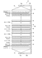
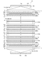
固体高分子形燃料電池(PEFC:Polymer Electrolyte Fuel Cell)の技術分野において、燃料電池用ガス(アノードガス、カソードガス)を均一に供給及び拡散させることが可能な燃料電池セルスタックが知られている(例えば、特許文献1参照。)。図26は、従来の燃料電池セルスタック920を模式的に示す正面図である。図27及び図28は、従来の燃料電池セルスタック920におけるタイプCAのセパレータ921の平面図である。このうち図27は燃料電池用ガス供給拡散層(カソードガス供給拡散層)942側から見た平面図であり、図28は燃料電池用ガス供給拡散層(アノードガス供給拡散層)941側から見た平面図である。図29は、図27のA−A線に沿った断面図である。
In the technical field of polymer electrolyte fuel cells (PEFCs), fuel cell stacks capable of uniformly supplying and diffusing fuel cell gases (anode gas, cathode gas) are known. (See, for example,
従来の燃料電池セルスタック920は、図26〜図29に示すように、金属板30の少なくとも一方の面に多孔質体層による燃料電池用ガス供給拡散層が設けられた構造の複数のセパレータ(タイプCAのセパレータ921、タイプAのセパレータ922、タイプCのセパレータ923、タイプAWのセパレータ924)が積層された構造を有する。なお、タイプCAのセパレータ921、タイプAのセパレータ922及びタイプAWのセパレータ924の「A」は燃料電池用ガス供給拡散層(アノードガス供給拡散層)941を表し、タイプCAのセパレータ921及びタイプCのセパレータ923の「C」は燃料電池用ガス供給拡散層(カソードガス供給拡散層)942を表し、タイプAWのセパレータ924の「W」は冷却水供給拡散層を表す。従来の燃料電池セルスタック920によれば、セパレータそのものに多孔質体層からなる燃料電池用ガス供給拡散層941,942が形成されていることから、燃料電池用ガスを燃料電池用ガス供給拡散層の全面にわたって均一に拡散できる。その結果、燃料電池用ガスを膜電極接合体(MEA)81の全面にわたって均一に供給でき、燃料電池の発電効率を従来よりも高くできる。
As shown in FIGS. 26 to 29, the conventional
ところで、燃料電池の技術分野においては、従来よりも燃料電池の発電効率を高くできる技術が求められており、固体高分子形燃料電池の技術分野においても同様である。そこで、本発明は、従来よりも燃料電池の発電効率を高くできる、燃料電池用ガス供給拡散層、燃料電池用セパレータ及び燃料電池セルスタックを提供することを目的とする。 By the way, in the technical field of fuel cells, a technology capable of increasing the power generation efficiency of fuel cells is required, and the same is true in the technical field of polymer electrolyte fuel cells. Therefore, an object of the present invention is to provide a gas supply diffusion layer for a fuel cell, a separator for a fuel cell, and a fuel cell stack capable of increasing the power generation efficiency of the fuel cell as compared with the conventional case.
本発明の一実施形態による燃料電池用ガス供給拡散層は、燃料電池用ガス供給拡散層であって、ガスの透過及び拡散が可能で、かつ、導電性を有するシート状の多孔質体層と、前記多孔質体層の一方の面において並列に、かつ、それぞれが前記ガスの流入側から流出側に向かってジグザグ状又は波状に形成された複数のガス流路用溝とを有し、平面的に見て、前記複数のガス流路用溝のうちそれぞれのガス流路用溝が外接する複数の矩形領域Rのうち、一のガス流路用溝が外接する第1矩形領域R1と、前記一のガス流路用溝に隣接するガス流路用溝が外接する第2矩形領域R2とがその接する領域に沿って重なっており、かつ、前記第1矩形領域R1と前記第2矩形領域R2とが重なる重なり領域R3が、前記複数のガス流路用溝の断面形状を問わず前記複数のガス流路用溝のどの深さ位置においても存在する。 The gas supply / diffusion layer for a fuel cell according to an embodiment of the present invention is a gas supply / diffusion layer for a fuel cell, and is a sheet-like porous body layer capable of permeating and diffusing gas and having conductivity. , Each having a plurality of gas flow path grooves formed in parallel on one surface of the porous body layer and in a zigzag shape or a wavy shape from the inflow side to the outflow side of the gas, and is a flat surface. In view of the above, among the plurality of rectangular regions R to which the respective gas flow path grooves circulate among the plurality of gas flow path grooves, the first rectangular region R1 to which one gas flow path groove circulates, and The second rectangular region R2 to which the gas flow path groove adjacent to the one gas flow path groove is in contact overlaps along the tangent region, and the first rectangular region R1 and the second rectangular region are overlapped with each other. An overlapping region R3 that overlaps with R2 exists at any depth position of the plurality of gas flow path grooves regardless of the cross-sectional shape of the plurality of gas flow path grooves.
本発明の一実施形態による燃料電池用セパレータは、ガス遮蔽板と、前記ガス遮蔽板の少なくとも一方の面に配設された燃料電池用ガス供給拡散層とを備える燃料電池用セパレータであって、前記燃料電池用ガス供給拡散層は、本発明の燃料電池用ガス供給拡散層であり、前記燃料電池用ガス供給拡散層は、前記複数のガス流路用溝が前記ガス遮蔽板側に位置するように前記ガス遮蔽板に対して配置されており、前記ガス流路用溝と前記ガス遮蔽板とでガス流路が構成されている。 The fuel cell separator according to the embodiment of the present invention is a fuel cell separator provided with a gas shielding plate and a fuel cell gas supply / diffusion layer arranged on at least one surface of the gas shielding plate. The gas supply / diffusion layer for a fuel cell is the gas supply / diffusion layer for a fuel cell of the present invention, and in the gas supply / diffusion layer for a fuel cell, the plurality of gas flow path grooves are located on the gas shielding plate side. As described above, the gas flow path is formed with respect to the gas shielding plate, and the gas flow path groove and the gas shielding plate form a gas flow path.
本発明の一実施形態による燃料電池セルスタックは、燃料電池用セパレータと、膜電極接合体とが積層されてなる燃料電池セルスタックであって、前記燃料電池用セパレータは、本発明の燃料電池用セパレータであり、前記燃料電池用セパレータと前記膜電極接合体とは、前記燃料電池用ガス供給拡散層の前記複数のガス流路用溝が形成されていない側の面に前記膜電極接合体が位置する位置関係で積層されている。 The fuel cell stack according to an embodiment of the present invention is a fuel cell stack in which a fuel cell separator and a membrane electrode assembly are laminated, and the fuel cell separator is for a fuel cell of the present invention. It is a separator, and the fuel cell separator and the membrane electrode assembly have the membrane electrode assembly on the surface of the fuel cell gas supply diffusion layer on the side where the plurality of gas flow path grooves are not formed. They are stacked in a positional relationship.
本発明の一実施形態による燃料電池用ガス供給拡散層、燃料電池用セパレータ及び燃料電池セルスタックによれば、従来よりも燃料電池の発電効率を高くでき、さらには、従来よりも排水性に優れた、燃料電池用ガス供給拡散層、燃料電池用セパレータ及び燃料電池セルスタックとなる。 According to the gas supply diffusion layer for a fuel cell, the separator for a fuel cell, and the fuel cell stack according to one embodiment of the present invention, the power generation efficiency of the fuel cell can be made higher than before, and the drainage property is superior to that of the conventional one. It also serves as a gas supply diffusion layer for fuel cells, a separator for fuel cells, and a fuel cell cell stack.
以下、本発明の燃料電池用ガス供給拡散層、燃料電池用セパレータ及び燃料電池セルスタックを図に示す実施形態を用いて詳細に説明する。 Hereinafter, the gas supply diffusion layer for a fuel cell, the separator for a fuel cell, and the fuel cell stack of the present invention will be described in detail with reference to the embodiments shown in the figure.
[実施形態]
図1は、実施形態に係る燃料電池セルスタック20を模式的に示す正面図である。図2は、実施形態に係る燃料電池セルスタック20を模式的に示す側面図である。[Embodiment]
FIG. 1 is a front view schematically showing the
実施形態に係る燃料電池スタック20は、固体高分子形燃料電池(PEFC:Polymer Electrolyte Fuel Cell)である。燃料電池スタック20は、複数の単セルを有する。燃料電池スタック20の各セルは、膜電極接合体81と、膜電極接合体81を挟んでカソード側を構成する要素とアノード側を構成する要素とを有する。
The
燃料電池用セパレータ21は、ガス遮蔽板としての金属板30の一方の面にカソードガス供給拡散層Cが形成され、他方の面にアノードガス供給拡散層Aが形成されている(タイプCAのセパレータ)。燃料電池用セパレータ22は、金属板30の一方の面にアノードガス供給拡散層Aが形成されている(タイプAのセパレータ)。燃料電池用セパレータ23は、金属板30の一方の面にカソードガス供給拡散層Cが形成されている(タイプCのセパレータ)。燃料電池用セパレータ24は、金属板30の一方の面にカソードガス供給拡散層Cが形成され、他方の面に冷却水供給拡散層Wが形成されている(タイプCWのセパレータ)。
In the
各セルは、カソード側とアノード側が交互になるように配置されている。カソードガス供給拡散層Cとアノードガス供給拡散層Aとは、膜電極接合体(MEA)81を挟んで対向して設けられている。実施形態においては、単セルが2つ配置される毎に冷却水を供給する冷却水供給拡散層Wが設けられている。なお、冷却水供給拡散層Wは、単セル1つ置きに設けられていてもよいし、3つ置き又はそれ以上置きに設けられていてもよい。冷却水供給拡散層Wには金属板30(好ましくはタイプAまたはタイプCのセパレータにおける金属板30)が対向するように、燃料電池用セパレータ21〜24が組み合わされて積層されている。
Each cell is arranged so that the cathode side and the anode side alternate. The cathode gas supply / diffusion layer C and the anode gas supply / diffusion layer A are provided so as to face each other with the membrane electrode assembly (MEA) 81 interposed therebetween. In the embodiment, a cooling water supply diffusion layer W for supplying cooling water is provided every time two single cells are arranged. The cooling water supply / diffusion layer W may be provided every other single cell, or may be provided every three or more.
なお、本発明の燃料電池セルスタックは、図1及び図2には図示していないが、金属板30の一方の面にアノードガス供給拡散層Aが形成され、他方の面に冷却水供給拡散層Wが形成されたもの(タイプAWのセパレータ)を備えていてもよい。また、金属板30の一方の面に冷却水供給拡散層Wが形成されたセパレータ(タイプWのセパレータ)を備えていてもよい。また、金属板の両面に冷却水供給拡散層Wが形成されたセパレータを備えていてもよい。各燃料電池用セパレータの構成の詳細については後述する。
Although not shown in FIGS. 1 and 2, the fuel cell stack of the present invention has an anode gas supply / diffusion layer A formed on one surface of the
積層されたセルの両端部には、集電板27A,27Bが配設されている。さらに集電板27A、27Bの外側には、絶縁シート28A,28Bを介してエンドプレート75,76が配置されている。燃料電池用セパレータ21〜24は、エンドプレート75、76によって両側から押圧されている。燃料電池セルスタック20の両端に位置し、集電板27A,27Bに接する燃料電池用セパレータについては、その金属板30(耐食層)が外方を向くようにすることが好ましい。
図1及び図2においては、燃料電池用セパレータ21〜24、膜電極接合体81、集電板27A,27B、絶縁シート28A,28B、及び、エンドプレート75,76は、分かり易くするために、離間して描かれているが、これらは、図示された配列の順に、相互に密に接合されている。接合の方法は特に限定されない。例えば、エンドプレート75,76により各部材を両側から押圧することのみによって接合してもよいし、各部材の適宜の位置を接着剤により接着したうえでエンドプレート75,76により各部材を両側から押圧することにより接合してもよいし、その他の方法により接合してもよい。各燃料電池用セパレータ21〜24、膜電極接合体81、集電板27A,27B、絶縁シート28A,28B等は、例えば厚さが百μm程度から十mm程度である。本明細書の各実施形態における各図は、厚さを誇張して描かれている。
In FIGS. 1 and 2, the
アノード側のエンドプレート75の一端部にはアノードガス供給口71A、カソードガス排出口72B及び冷却水排出口73Bがそれぞれ設けられている。他方、カソード側のエンドプレート76の一端部(エンドプレート75の上記一端部とは反対側)には、アノードガス排出口71B、カソードガス供給口72A及び冷却水供給口73A(図2ではこれらがまとめて破線で示されている)が設けられている。これらの各供給口、各排出口にはそれぞれ対応する流体の供給管、排出管が接続されることになる。
An anode
各燃料電池用セパレータ21〜24には、それぞれ、アノードガス供給口71Aに連通するアノードガス流入口61A、カソードガス排出口72Bに連通するカソードガス(及び生成水)流出口62B、及び、冷却水排出口73Bに連通する冷却水流出口63Bが設けられている。また、各燃料電池用セパレータ21〜24には、それぞれ、アノードガス排出口71Bに連通するアノードガス流出口61B、カソードガス供給口72Aに連通するカソードガス流入口62A、及び、冷却水供給口73Aに連通する冷却水流入口63Aが設けられている。
The
アノードガス供給口71A、カソードガス供給口72A及び冷却水供給口73Aを通じてカソードガス、アノードガス及び冷却水が供給される。実施形態においては、アノードガスとして水素ガスを使用し、カソードガスとして空気を用いた場合を例示する。
Cathode gas, anode gas and cooling water are supplied through the anode
次に、膜電極接合体81について説明する。
図3は、膜電極接合体(MEA)81を説明するために示す図である。図3(a)は膜電極接合体81の平面図であり、図3(b)は膜電極接合体81の正面図であり、図3(c)は膜電極接合体の側面図である。Next, the
FIG. 3 is a diagram shown for explaining the membrane electrode assembly (MEA) 81. FIG. 3A is a plan view of the
膜電極接合体81は、図3に示すように、電解質膜(PEM)82と、電解質膜82の両面にそれぞれ配置された触媒層(CL)85と、各触媒層85の外側の面に配置されたマイクロポーラスレイヤ(MPL)83とを有する。実施形態においては、電解質膜82とその両側に配置された触媒層85から構成されるものを触媒コート電解質膜(Catalyst Coated Membrame:CCM)という。マイクロポーラスレイヤ83は多孔質体層40よりも微細な径の気孔(細孔)を有する。なお、マイクロポーラスレイヤ83は、省略することもできる。
As shown in FIG. 3, the
次に、燃料電池用セパレータ21〜24及び燃料電池用ガス供給拡散層42について説明する。
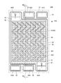
図4は、タイプCの燃料電池用セパレータ23の金属板30の側から見た平面図である。但し、図4においては、燃料電池用セパレータ23の流路パターンを分かり易く表すために、金属板30の図示は省略している。図5は、図4の断面図である。図5(a)は図4のA1−A4断面図(但し、A2−A3部分は省略)であり、図5(b)は図4のA2−A3断面図である。図5においては、燃料電池用セパレータ23と膜電極接合体81との位置関係を示すために、膜電極接合体81が接合された状態の燃料電池用セパレータ23を示している。また、膜電極接合体81の断面構造は省略している。Next, the
FIG. 4 is a plan view of the type C
図6は、ガス流路用溝55の平面構造を示す図である。図7は、ガス流路用溝55の平面構造及び断面構造を示す図である。図7(a)は平面図であり、図7(b)は図7(a)のA−A断面図である。図8は、異なる深さ位置におけるガス流路用溝55の平面構造を示す図である。図8(a)は深さ位置D1(多孔質体層40(又はガス流路用溝55)の表面における深さ位置)におけるガス流路用溝55の平面構造を示し、図8(b)は深さ位置D2(ガス流路用溝55の深さの1/2の深さ位置)におけるガス流路用溝55の平面構造を示し、図8(c)は深さ位置D3(ガス流路用溝55の底における深さ位置)におけるガス流路用溝55の平面構造を示す。
FIG. 6 is a diagram showing a planar structure of the gas
図6及び図7において、符号55はガス流路用溝を示し、符号55Aはガス流路用溝55のうち一のガス流路用溝を示し、符号55Bは一のガス流路用溝55Aに隣接するガス流路用溝を示す。従って、一のガス流路用溝55Aは、ガス流路用溝55でもあることからガス流路用溝55(55A)と表記することもあり、一のガス流路用溝55Aに隣接するガス流路用溝55Bも、ガス流路用溝55でもあることからガス流路用溝55(55B)という符号を付すこともある。また、図6中、太実線で囲まれた領域が第1矩形領域R1であり、その左右の太破線で囲まれた領域が第2矩形領域R2であり、第1矩形領域R1と第2矩形領域R2とが重なった領域が重なり領域R3であり色を濃くして示している。また、符号Rは複数のガス流路用溝55のうちそれぞれのガス流路用溝が外接する矩形領域を示し、符号R1はそのうち一のガス流路用溝55Aが外接する第1矩形領域を示し、符号R2は一のガス流路用溝55Aに隣接するガス流路用溝55Bが外接する第2矩形領域を示し、符号R3は第1矩形領域R1と第2矩形領域R2とが重なる重なり領域を示す。従って、第1矩形領域R1は、矩形領域Rでもあることから第1矩形領域R(R1)と表記することもあり、第2矩形領域R2も、矩形領域Rでもあることから第2矩形領域R(R2)と表記することもある。また、図7(a)中、符号L2はガス流路用溝55の配列ピッチを示す。
In FIGS. 6 and 7,
図7及び図8においては、カソードガスの流れを図示している。図7(a)及び図8中、ガス流路用溝55内の矢印はガス流路用溝55に沿った流れであり、多孔質体層40内に記した縦方向上向きの矢印はガス流路用溝55から多孔質体層40(ガス拡散層43)中に押し出されたカソードガスの流れ(伏流ガス流れ)である。また、図7(b)中、多孔質体層40内に記した横方向及び下方向(膜電極接合体側に向かう方向)向きの矢印は、ガス流路用溝55から多孔質体層40(ガス拡散層43)中に押し出されたカソードガスの流れを示す。図9は、第1矩形領域R1、第2矩形領域R2及び重なり領域R3の関係を示す図である。
7 and 8 show the flow of the cathode gas. In FIGS. 7A and 8A, the arrow in the gas flow path groove 55 is the flow along the gas
燃料電池用セパレータ23は、図4及び図5に示すように、金属板30の一方の面に燃料電池用ガス供給拡散層42が形成された構造を有する。図5中、金属板30には、断面であることを示すハッチングを施している。金属板30は、インコネル、ニッケル、金、銀及び白金のうち一以上からなる金属、またはオーステナイト系ステンレス鋼板への金属のめっきもしくはクラッド材であることが好ましい。これらの金属を用いることにより、耐食性を向上できる。
As shown in FIGS. 4 and 5, the
燃料電池用セパレータ23においては、金属板30の縦方向の一端部(図4の下部)に、図4の右、中央、左の順に、カソードガス流入口62Aと、冷却水流入口63Aと、アノードガス流出口61Bとが設けられている。また、他端部(図4の上部)に、図4の左、中央、右の順に、カソードガス流出口62Bと、冷却水流出口63Bと、アノードガス流入口61Aとが設けられている。
In the
各流入口61A,62A,63A、各流出口61B,62B,63B、及び、燃料電池用ガス供給拡散層42の形成領域のそれぞれの周囲は、電子導電性又は非電子導電性の緻密枠32によって囲まれている。緻密枠32はアノードガス、カソードガス及び冷却水の漏洩を防ぐ。緻密枠32の外面には、各流入口61A,62A,63A、各流出口61B,62B,63B、及び、燃料電池用ガス供給拡散層42の形成領域を囲むように、緻密枠32に沿って溝33Aが形成されている(図4には不図示。)。この溝33A内にガスケット(パッキン、Oリングなどのシール材)33が配置されている。
The perimeters of the
金属板30の両面には、上記の各流入口61A,62A,63A、及び、各流出口61B,62B,63Bが設けられている部分を除いて、その全面に電子導電性を有する耐食層(図5においては図示せず)が形成されている。各流入口61A,62A,63A、及び、各流出口61B,62B,63Bの内周面に耐食層が形成されていてもよい。金属板30の側面及び端面に耐食層が形成されていてもよい。耐食層は、好ましくは緻密枠32と同じ組成の緻密層であり、金属板30の腐食を抑制する作用を有する。燃料電池用セパレータを組み合わせて図1あるいは図2に示すような燃料電池セルスタックを構成する段階で、ガスケット33は接合される他の燃料電池用セパレータ、膜電極接合体81又は集電板27A,27Bと密着して流体の漏洩を抑制する。
Corrosion-resistant layers having electron conductivity on both sides of the
燃料電池用セパレータ23は、タイプCの燃料電池用セパレータであって、図4及び図5に示すように、基板としての長方形の金属板30の一方の面における中央部にカソードガスを供給・拡散する燃料電池用ガス供給拡散層42が形成されている。燃料電池用ガス供給拡散層42は、ガスの透過及び拡散が可能で、かつ、導電性を有するシート状の多孔質体層40と、多孔質体層40の一方の面において並列に、かつ、それぞれがガスの流入側から流出側に向かってジグザグ状又は波状に形成された複数のガス流路用溝55と、多孔質体層40のうちガス流路用溝55以外の部分であるガス拡散層43とを有する(図4参照。)。
The
そして、平面的に見て、複数のガス流路用溝55のうちそれぞれのガス流路用溝55が外接する複数の矩形領域Rのうち、一のガス流路用溝55が外接する第1矩形領域R1と、一のガス流路用溝に隣接するガス流路用溝が外接する第2矩形領域R2とがその接する領域に沿って重なっている(図6及び図9参照。)。また、第1矩形領域R1と第2矩形領域R2とが重なる重なり領域R3が、複数のガス流路用溝55の断面形状を問わず複数のガス流路用溝55のどの深さ位置D1,D2,D3においても存在する(図7及び図8参照。)。
Then, when viewed in a plane, the first gas flow path groove 55 out of the plurality of rectangular regions R to which each gas flow path groove 55 of the plurality of gas
なお、本明細書において、「矩形領域」とは、複数のガス流路用溝のうちそれぞれのガス流路用溝が外接する矩形領域Rであるが(図6及び7参照。)、多孔質体層40に、複数のガス流路用溝と交差するように、ガスの流入側から流出側に向かう方向に直交する幅方向全体にわたって、1又は複数のガス圧均等化用溝が形成されている場合には(例えば後述する図12参照。)、当該ガス圧均等化用溝によって分割された領域に形成されるそれぞれの矩形領域Rに関しても、その幅及び/又は長さの違いにかかわらず、本発明の矩形領域に含まれるものとする。また、本明細書において、「伏流領域」とは、矩形領域のうちガス流路用溝55を除いた領域のことをいい、当該伏流領域中、多くのガスは流出側に向かって最短距離の経路に沿って流れることとなる。
In the present specification, the "rectangular region" is a rectangular region R in which each of the gas flow path grooves circumscribes among the plurality of gas flow path grooves (see FIGS. 6 and 7), but is porous. One or more gas pressure equalizing grooves are formed in the
また、本明細書において、「ガスの流入側から流出側に向かって」とは、「およそガスの流れる方向に沿って」という意味であり、「ガスの流入側から流出側に向かう」方向は、多孔質体層40全体としてみた場合の多孔質体層40内のガスの流れの方向である。これは、実施形態に係る燃料電池用ガス供給拡散層42のように、カソードガス流入口62Aとカソードガス流出口62Bが金属板30の対角線上の位置に配設されている場合に、ガス流路は上記の対角線に沿って形成されている必要はなく、実施形態のように、「ガスの流入側から流出側に向かう」方向は、「多孔質体層40全体としてみた場合の多孔質体層40内のガスの流れの方向が、図4の紙面の下から上の縦方向に向かうような場合は」、図4のように、図4の紙面の下から上の縦方向に沿ってガス流路用溝は形成されていればよいし、また、それ以外の方向に沿って形成されていてもよい。なお、ガス圧均等化用溝は、「ガスの流入側から流出側に向かう」方向、すなわち多孔質体層40全体としてみた場合の多孔質体層40内のガスの流れの方向に対して略直交するように配されるとよい。
Further, in the present specification, "from the gas inflow side to the outflow side" means "approximately along the gas flow direction", and the direction "from the gas inflow side to the outflow side" is , The direction of gas flow in the
ここで、ガス流入側溝51、ガス流出側溝52又はガス圧均等化用溝56に挟まれた部分に形成され、かつ、多孔質体層40端部、ガス流入側溝51、ガス流出側溝52、ガス圧均等化用溝56のいずれか2つの隣り合う多孔質体層40端部又は溝と連通するように(換言すると、複数溝(51,52,56)及び多孔質体層40端部のいずれか2つの隣り合う多孔質体層40端部又は溝(51,52,56)の間に形成され、これら隣り合う2つの多孔質体層40端部又は溝(51,52,56)と連通するように)形成され、並列に配置された複数のガス流路用溝55の各々について、このガス流路用溝55が外接する矩形領域を矩形領域Rとしている。従って、上記のように「第1矩形領域R1と第2矩形領域R2とがその接する領域に沿って重なる」ように構成する、すなわち、図9(a)に示すように、ガス流路用溝(矩形領域R)の配列ピッチL2と、矩形領域R(第1矩形領域R1及び第2矩形領域R2)の幅Lとを、L2<Lの関係を満たすようにすると、隣り合うジグザグ状のガス流路用溝55の一方の谷側に他方の山側が互いの流路が重ならない程度に突き出すような構成となる。なお、多孔質体層40端部は多孔質体層40の端の近傍を含むものとする。
Here, the portion sandwiched between the gas
実施形態に係る燃料電池用ガス供給拡散層42においては、重なり領域R3の幅L1と、矩形領域R(第1矩形領域R1及び第2矩形領域R2)の幅Lとが、「L1≧0.1×L」の関係を満たすことが好ましく、「L1≧0.2×L」の関係を満たすことがより好ましく、「L1≧0.3×L」の関係を満たすことがさらに好ましい(図7参照。)。
In the fuel cell gas supply /
カソードガスとしての空気(酸素ガス及び窒素ガス)は、多孔質体層40(ガス拡散層43)内を拡散する。多孔質体層40は、導電材(好ましくは炭素系導電材)と高分子樹脂の混合物を含む。高分子樹脂に炭素系導電材を混合することにより、高分子樹脂に高い導電性を付与することができ、また高分子樹脂の結着性により炭素材の成型性を向上させることができる。多孔質体層40の流体抵抗は、多孔質体層の気孔率と流体の流れる面の面積に依存する。気孔率が大きくなれば流体抵抗は小さくなる。流体が流れる面積が大きくなれば流体抵抗は小さくなる。およその目安としては、(カソードガス用の)燃料電池用ガス供給拡散層42においては、多孔質体層40の気孔率は、50〜85%程度である。なお、(アノードガス用の)燃料電池用ガス供給拡散層41においては、多孔質体層40の気孔率は、30〜85%程度である。
Air (oxygen gas and nitrogen gas) as a cathode gas diffuses in the porous body layer 40 (gas diffusion layer 43). The
多孔質体層40の気孔率が上記のように構成されていることから、ガス流路用溝55の内表面を介して、ガス流路用溝55と多孔質体層40との間のカソードガス、水蒸気、凝結水の流通が適切に行われるようになる結果、多量の燃料電池用ガスを膜電極接合体に対して均一に供給できるようになり、また、発電時に使用されなかったカソードガスや発電時に生成した水蒸気や凝結水をガス流路用溝外に効率よく排出することができるようになる。その結果、ガス流路用溝55の内表面に、金属、セラミックス、樹脂等からなるガス不透過層に微細なガス流通孔を多数開口したガス透過フィルターのようなものを形成する必要も無い。
Since the pore ratio of the
炭素系導電材の含有率を調整することにより、燃料電池用ガス供給拡散層42の気孔率を調整することができ、ひいては、燃料電池用ガス供給拡散層42の移動抵抗を調整することができる。特に炭素系導電材の含有率を高くすると移動抵抗が小さくなる(気孔率が大きくなる)。逆に、炭素系導電材の含有率を低くすると移動抵抗が大きくなる(気孔率が小さくなる)。耐食層及び緻密枠32も炭素系導電材と高分子樹脂の混合物であり、炭素系導電材の適度な含有率により、導電性を確保しつつ緻密化したものであるのが好ましい。
By adjusting the content of the carbon-based conductive material, the porosity of the fuel cell gas supply /
炭素系導電材としては特に限定されないが、例えば黒鉛、カーボンブラック、ダイヤモンド被覆カーボンブラック、炭化ケイ素、炭化チタン、カーボン繊維、カーボンナノチューブ等を用いることができる。高分子樹脂としては、熱硬化性樹脂及び熱可塑性樹脂のいずれも用いることができる。高分子樹脂の例としては、フェノール樹脂、エポキシ樹脂、メラミン樹脂、ゴム系樹脂、フラン樹脂、フッ化ビニリデン樹脂等が挙げられる。 The carbon-based conductive material is not particularly limited, and for example, graphite, carbon black, diamond-coated carbon black, silicon carbide, titanium carbide, carbon fibers, carbon nanotubes, and the like can be used. As the polymer resin, either a thermosetting resin or a thermoplastic resin can be used. Examples of the polymer resin include phenol resin, epoxy resin, melamine resin, rubber resin, furan resin, vinylidene fluoride resin and the like.
カソードガス流入口62Aと多孔質体層40が形成されている領域との間には流入通路57が形成されている(図4参照。)。カソードガス流出口62Bと多孔質体層40が形成されている領域との間には流出通路58が形成されている。これらの流入通路57及び流出通路58は膜電極接合体81又はそのフレーム81Aを支持するためのものである。したがって、カソードガスを円滑に流し、かつ膜電極接合体81をサポートできる構造であればよい。例えば、気孔率のきわめて大きい多孔質層でもよいし、多数の支柱を配列した構造でもよい。多孔質体層40における流入通路57と面する領域には金属板30の幅方向に沿って細長い流入側溝51が形成されている。また、多孔質体層40における流出通路58と面する領域にも金属板30の幅方向に沿って細長い流出側溝52が形成されている。但し、流入側溝51及び流出側溝52は、これらを省略することもできる。
An
多孔質体層40、流入通路57、及び流出通路58は、図5に示すように、緻密枠32と同じ高さ(厚さ)に形成されている。燃料電池用ガス供給拡散層42における金属板30に対向する側の面には、空隙からなる複数のガス流路用溝55が設けられており、これら複数のガス流路用溝55と金属板30との隙間に複数のガス流路が形成されている。ガス流路用溝55は所定の間隙で複数形成されている。各ガス流路用溝55は、流入側においては流入側溝51を介して流入通路57と連通し、流出側においては流出側溝52を介して流出通路58と連通している。ガス流路用溝55の数及び構造は図示のものに限定されない。
As shown in FIG. 5, the
実施形態に係る燃料電池用ガス供給拡散層42は、これを輸送機器用の燃料電池に用いる場合には、輸送機器の種類・大きさにもよるが、多孔質体層40の横幅は例えば30mm〜300mm程度である。ガス流路用溝55の幅Wは例えば0.3mm〜2mm程度である。多孔質体層40の厚さは例えば150〜400μm程度であり、ガス流路用溝55の深さは例えば100〜300μm程度であり、ガス流路用溝の底と多孔質体層40の他方の面との距離(天井厚)は例えば100〜300μm程度である。実施形態に係る燃料電池用ガス供給拡散層42を輸送機器以外の用途(例えば定置用)の燃料電池に用いる場合には、上記のサイズに限定されるものではなく、必要とされる性能などに応じて適宜のサイズのものを用いることができる。ガス流路用溝55は、図4に示すように、ジグザグ形状をなしている。すなわち、ガス流路用溝55は、直線部551と、空気の流れる方向を変える角部552とを有している。直線部551の長さや、角部552の角度は図示のものに限定されない。例えば、図4においては角部552の角度はほぼ直角であるが、鋭角であってもよく、鈍角であってもよい。また、角部552は、適宜の面取り処理や丸め処理が施されていてもよい。
When the gas supply /
実施形態に係る燃料電池用ガス供給拡散層42においては、図4に示すように、各直線部551の長さおよび各角部552の形状はいずれも等しい。そして、上記したように、平面的に見て、複数のガス流路用溝55のうちそれぞれのガス流路用溝が外接する複数の矩形領域(長方形領域)Rを定義したとき、一のガス流路用溝55が外接する第1矩形領域R1と、一のガス流路用溝に隣接するガス流路用溝55が外接する第2矩形領域R2とがその接する領域に沿って重なっており(図6参照。)、かつ、第1矩形領域R1と第2矩形領域R2とが重なる重なり領域R3が、複数のガス流路用溝55のどの深さ位置D1,D2,D3においても存在する(図7及び図8参照。)。
In the fuel cell gas supply /
タイプAの燃料電池用セパレータ22における燃料電池用ガス供給拡散層41も、基本的には燃料電池用ガス供給拡散層42と同様の構成を有する。但し、燃料電池用ガス供給拡散層に供給するガスが水素ガスであることから、燃料電池用ガス供給拡散層42よりも気孔率が低く、また、厚さが薄い(後述する図10(b)参照。)。
The fuel cell gas supply /
タイプCAの燃料電池用セパレータ21においては、燃料電池用ガス供給拡散層として燃料電池用ガス供給拡散層41及び燃料電池用ガス供給拡散層42を用いる(後述する図10(a)参照。)。タイプCWの燃料電池用セパレータ24は、タイプCの燃料電池用セパレータ23における燃料電池用ガス供給拡散層42が形成されていない面に冷却水供給拡散層が形成されたものである(後述する図10(c)参照。)。タイプAWの燃料電池用セパレータ25は、タイプAの燃料電池用セパレータ22における燃料電池用ガス供給拡散層41が形成されていない面に冷却水供給拡散層が形成されたものである(後述する図10(d)参照。)。
In the type CA
燃料電池スタック20を運転すると、アノードガス(水素ガス)を導入する燃料極ではプロトン(H+)が生成する。プロトンは、膜電極接合体81中を拡散して酸素極側に移動し、酸素と反応して水が生成する。生成した水は、酸素極側から排出される。このとき、上記のような構造を有する燃料電池用ガス供給拡散層42を備える燃料電池用セパレータ23においては、カソードガス流入口62Aから流入した空気は流入通路57及び流入側溝51を通って、ガス流路用溝55に流入する。流入側溝51内に流入した空気の一部はガス流路用溝55内に入ってガス流路用溝55から多孔質体層40(ガス拡散層43)内に入り、他の一部は多孔質体層40(ガス拡散層43)の端面から直接に多孔質体層40(ガス拡散層43)に入って、多孔質体層40(ガス拡散層43)内を拡散していく。
When the
空気は、多孔質体層40(ガス拡散層43)内を平面方向に拡散しながら厚さ方向にも拡散し、多孔質体層40(ガス拡散層43)に接して設けられた膜電極接合体81に供給され、発電反応に寄与する。発電に使用されなかったガス(未使用の酸素ガス及び窒素ガス)及び発電時に生成した水(水蒸気又は凝縮水)は多孔質体層40(ガス拡散層43)、ガス流路用溝55、流出側溝52を介して流出通路58に流出する。流出通路58に流出した酸素ガス、窒素ガス及び水は、最終的に流出通路58からカソードガス流出口62B及びカソードガス排出口72Bを通って排出されていく。このとき、燃料電池用ガス供給拡散層42の構造上、全ての水は排出されず、一部が多孔質体層40(ガス拡散層43)内に留まる。
The air diffuses in the thickness direction while diffusing in the planar direction in the porous body layer 40 (gas diffusion layer 43), and is provided in contact with the porous body layer 40 (gas diffusion layer 43). It is supplied to the
実施形態に係る燃料電池用ガス供給拡散層42は、上記のような特徴を有することから、発電時に膜電極接合体で生成した水(水蒸気又は凝縮水)を、多孔質体層40及びガス流路用溝55を介してガス流路用溝外に効率良く排出できるようになる。また、伏流領域においては伏流ガス流れに押し出される形で水をガス流路用溝外に効率良く排出できるようになる。
Since the fuel cell gas supply /
[実施形態の効果]
実施形態に係る燃料電池用ガス供給拡散層42によれば、多孔質体層40の一方の面において複数のガス流路用溝55が形成されていることから、従来よりも燃料電池用ガスの移動抵抗が減少し、膜電極接合体に対して従来よりも多量の燃料電池用ガスを供給できる。[Effect of Embodiment]
According to the fuel cell gas supply /
また、実施形態に係る燃料電池用ガス供給拡散層42によれば、複数のガス流路用溝55が多孔質体層40の一方の面に形成されていることから、多孔質体層40の他方の面に配設される膜電極接合体81に対する燃料電池用ガスの供給は必ず多孔質体層40を介して行われるので、複数のガス流路が多孔質体層の一方の面から他方の面にかけて開口されている場合よりも燃料電池用ガスを膜電極接合体に対して均一に供給できる。また、実施形態に係る燃料電池用ガス供給拡散層42によれば、多孔質体層40の一方の面に複数のガス流路用溝55がガスの流入側から流出側に向かってジグザグ状又は波状に形成されていることから、ガス流路用溝中のガス流れに限らず上流側流路と下流通路とを短絡して伏流するガス流れ(伏流ガス流れ)が形成されるため 、多孔質体層に供給される燃料電池用ガスの供給経路が面内に広く分散するようになり、複数のガス流路用溝がガスの流入側から流出側に向かって直線状に形成されている場合よりも燃料電池用ガスを膜電極接合体に対して均一に供給できる。
Further, according to the fuel cell gas supply /
また、実施形態に係る燃料電池用ガス供給拡散層42によれば、複数のガス流路用溝55のうち一のガス流路用55Aが外接する第1矩形領域R1においては、当該一のガス流路用溝55A中を流れる燃料電池用ガスの一部が多孔質体層40に入り込んでいわゆる伏流領域が第1矩形領域R1中に形成され、また、上記の一のガス流路用溝55Aに隣接するガス流路用溝55B中を流れる燃料電池用ガスの一部が多孔質体層40に入り込んでいわゆる伏流領域が第2矩形領域R2中に形成され、これらの第1矩形領域R1と第2矩形領域R2とがその接する領域に沿って重なっていることから(図6及び図7参照。)、多孔質体層40に供給される燃料電池用ガスの供給経路が面内に隙間無く分散するようになるため、ガス燃料電池用ガスを膜電極接合体81に対してより一層均一に供給できる。
Further, according to the fuel cell gas supply /
また、実施形態に係る燃料電池用ガス供給拡散層42によれば、第1矩形領域R1と第2矩形領域R2とが重なる重なり領域R3が、複数のガス流路用溝55のどの深さ位置D1,D2,D3においても存在することから(図7及び図8参照。)、多孔質体層40に供給される燃料電池用ガスの供給経路がガス流路用溝55のどの深さ位置D1,D2,D3においても面内に隙間無く分散するようになるため、燃料電池用ガスを膜電極接合体に対してより一層均一に供給できる。
Further, according to the fuel cell gas supply /
その結果、実施形態に係る燃料電池用ガス供給拡散層42は、従来よりも多量の燃料電池用ガスを膜電極接合体81に対して均一に供給できるようになることから、従来よりも燃料電池の発電効率を高くできる、燃料電池用ガス供給拡散層となる。
As a result, the fuel cell gas
また、実施形態に係る燃料電池用ガス供給拡散層42は、上記のような特徴を有することから、発電に使用されなかった燃料電池用ガス(この場合カソードガス(酸素ガス、窒素ガス))を、多孔質体層40及びガス流路用溝55を介してガス流路用溝55外に効率良く排出できるようになるため、また、伏流領域においては伏流ガス流れに押し出される形で発電に使用されなかった燃料電池用ガス(この場合カソードガス(酸素ガス、窒素ガス))をガス流路用溝55外に効率良く排出できるようになるため、従来よりも燃料電池用ガスの移動抵抗が低く保つこと、ひいては、反応ガス濃度を高く保つことが可能となり、従来よりも燃料電池の発電効率を高くできる、燃料電池用ガス供給拡散層となる。
Further, since the gas supply /
また、実施形態に係る燃料電池用ガス供給拡散層42は、上記のような特徴を有することから、発電時に膜電極接合体81で生成した水蒸気又は凝縮水を、多孔質体層40及びガス流路用溝55を介してガス流路用溝55外に効率良く排出できるようになるため、また、伏流領域においては伏流ガス流れに押し出される形で水蒸気又は凝縮水をガス流路用溝55外に効率良く排出できるようになるため、従来よりも排水性に優れた燃料電池用ガス供給拡散層となる。
Further, since the gas supply /
また、実施形態に係る燃料電池用ガス供給拡散層42によれば、重なり領域R3の幅L1と、矩形領域の幅Lとが、「L1≧0.1×L」の関係を満たすことから、燃料電池用ガス供給拡散層42に占める重なり領域R3の平面面積割合を大きくすることができ、燃料電池用ガスを膜電極接合体81に対してより一層均一に供給できる。
Further, according to the fuel cell gas supply /
実施形態に係る燃料電池用セパレータ23は、金属板30と、金属板30の少なくとも一方の面に配設された燃料電池用ガス供給拡散層とを備える燃料電池用セパレータであって、燃料電池用ガス供給拡散層が実施形態に係る燃料電池用ガス供給拡散層42であり、当該燃料電池用ガス供給拡散層42は、複数のガス流路用溝55が金属板30側に位置するように金属板30に対して配置されており、ガス流路用溝55と金属板30とでガス流路が構成されていることから、従来よりも燃料電池の発電効率を高くでき、さらには、従来よりも排水性に優れた、燃料電池用セパレータとなる。
The
実施形態に係る燃料電池セルスタック20は、燃料電池用セパレータと、膜電極接合体とが積層されてなる燃料電池セルスタックであって、燃料電池用セパレータが、実施形態に係る燃料電池用セパレータ23であり、当該燃料電池用セパレータ23と膜電極接合体81とは、燃料電池用ガス供給拡散層42の複数のガス流路用溝55が形成されていない側の面に膜電極接合体81が位置する位置関係で積層されていることから、従来よりも燃料電池の発電効率を高くでき、さらには、従来よりも排水性に優れた、燃料電池セルスタックとなる。
The
[燃料電池用セパレータ23の製造方法]
一例として、耐食層、緻密枠32、燃料電池用ガス供給拡散層42等は等方圧加圧により形成する。たとえば熱硬化性樹脂を用いる場合(熱可塑性樹脂でもよい)、炭素系導電材粉末(および、状況に応じて炭素繊維)、樹脂粉末および揮発性溶剤を混錬してペースト状にする。このペーストには、耐食層、および緻密枠用のもの、流体供給拡散層用のもの等、多数種類を用意しておく。そして、金属板30上に、耐食層、緻密枠32のパターン、燃料電池用ガス供給拡散層42のパターン等を順次プリント、スタンプ、絞り出し等により形成する。各パターンの形成ごとに溶剤を揮発させる。上記のすべてのパターンが形成された金属板30の全体を軟質の薄いゴムバックに入れ、真空に脱気した後、ゴムバックを耐圧容器に入れ、加熱流体を容器内に導入して、加熱流体で等方圧加圧して樹脂を硬化させる。緻密枠32、燃料電池用ガス供給拡散層42の高さ(厚さ)を最終的に同じ高さ(厚さ)にするために、樹脂硬化の際の収縮の程度に応じて、これらの各枠、壁、層等の高さ(厚さ)をパターン作製時に調整しておくことが好ましい。[Manufacturing method of fuel cell separator 23]
As an example, the corrosion resistant layer, the
一方で、金属板30上に耐食層を形成しておき、他方で緻密枠32、燃料電池用ガス供給拡散層42を形成し、最後にこれらを熱圧着して製造することもできる。このとき緻密枠32は金属板30上の耐食層と同時に作成してもよい。第1段階で金属板30上に耐食層と緻密枠32とを作成し、この後第2段階で燃料電池用ガス供給拡散層42のペーストを金属板30の耐食層上に順次印刷し、乾燥させた後、ロールプレス(ホットプレス)で硬化させて製造することもできる。
On the one hand, a corrosion resistant layer may be formed on the
または、次のような製造方法を用いることもできる。カーボンファイバー(CF)、少量の黒煙微粒子(GCB)及び結着剤となる熱可塑性もしくは熱硬化性または繊維状物を形成する樹脂を混錬してシート状に形成し、硬化する前のグリーンシート状態のときに、流入通路57、流出通路58、流入側溝51、流出側溝52及ガス流路用溝55に対応する形状の突起を有するスタンプ型をシートに押し当てて、流入通路57、流出通路58、流入側溝51、流出側溝52及ガス流路用溝55を形成する。最後にグリーンシートを熱処理し、これを耐食層が形成された金属板30に接着する。
Alternatively, the following manufacturing method can also be used. Carbon fiber (CF), a small amount of black smoke fine particles (GCB), and a resin that forms a thermoplastic or thermosetting or fibrous material that serves as a binder are kneaded to form a sheet, which is green before curing. In the sheet state, a stamp mold having protrusions having a shape corresponding to the
燃料電池用ガス供給拡散層42の移動抵抗(又は流体抵抗)は、多孔質体層40の気孔率と流体の流れる方向に直交する面の面積(各層の高さ(厚さ)と幅)に依存する。気孔率が大きくなれば移動抵抗は小さくなる。流体が流れる面積が大きくなれば移動抵抗は小さくなる(単位面積当りの移動抵抗は一定である)。おおよその目安としては、燃料電池用ガス供給拡散層の気孔率は、(アノードガス用)燃料電池用ガス供給拡散層42については30〜85%程度、(カソードガス用)燃料電池用ガス供給拡散層41については50〜85%程度である。気孔率Pは、測定が容易な、P=(多孔質体層中の気孔の体積)/(多孔質体層の体積)で定められる。ここで、気孔は外部に通じていない気孔を含む真の気孔である。
The movement resistance (or fluid resistance) of the gas
なお、上記した製造方法は、燃料電池用セパレータ23以外の燃料電池用セパレータ(燃料電池用セパレータ21、燃料電池用セパレータ22、燃料電池用セパレータ24及び燃料電池用セパレータ25)を製造する際にも適用できる。
The above-mentioned manufacturing method is also used when manufacturing a fuel cell separator (
[燃料電池用セパレータ23以外の燃料電池用セパレータ]
図10は、燃料電池用セパレータ23以外の燃料電池用セパレータ(燃料電池用セパレータ21、燃料電池用セパレータ22、燃料電池用セパレータ24及び燃料電池用セパレータ25)の断面図である。図10(a)はタイプCAの燃料電池用セパレータ21の断面図であり、図10(b)はタイプAの燃料電池用セパレータ22の断面図であり、図10(c)はタイプCWの燃料電池用セパレータ24の断面図であり、図10(d)はタイプAWの燃料電池用セパレータ25の断面図である。[Fuel cell separator other than fuel cell separator 23]
FIG. 10 is a cross-sectional view of a fuel cell separator (
本発明の燃料電池用ガス供給拡散層は、燃料電池用セパレータ21の(カソードガス用)燃料電池用ガス供給拡散層42及び/又は(アノードガス用)燃料電池用ガス供給拡散層41に適用することができる(図10(a)参照。)。また、本発明の燃料電池用ガス供給拡散層は、燃料電池用セパレータ22の(アノードガス用)燃料電池用ガス供給拡散層41に適用することができる(図10(b)参照。)。また、本発明の燃料電池用ガス供給拡散層は、燃料電池用セパレータ24の(カソードガス用)燃料電池用ガス供給拡散層42に適用することができる(図10(c)参照。)。また、本発明の燃料電池用ガス供給拡散層は、燃料電池用セパレータ25の(アノードガス用)燃料電池用ガス供給拡散層41に適用することができる(図10(b)参照。)。
The fuel cell gas supply / diffusion layer of the present invention is applied to the fuel cell gas supply / diffusion layer 42 (for cathode gas) and / or the fuel cell gas supply / diffusion layer 41 (for anode gas) of the
このように本発明の燃料電池用ガス供給拡散層を上記のような燃料電池用セパレータ21,22,24,25の燃料電池用ガス供給拡散層に適用した場合であっても、従来よりも多量の燃料電池用ガスを膜電極接合体に対して均一に供給できるようになることから、従来よりも燃料電池の発電効率を高くできる、燃料電池用ガス供給拡散層となる。
As described above, even when the gas supply / diffusion layer for a fuel cell of the present invention is applied to the gas supply / diffusion layer for a fuel cell of the
[変形例1]
図11は、変形例1に係る燃料電池用ガス供給拡散層42aの(金属板30の側から見た)平面構造を説明するために示す図である。但し、図4の場合と同様に、燃料電池用セパレータ23の流路パターンを分かり易く表すために、金属板30の図示は省略している。以降の図12〜図21においても同様である。変形例1に係る燃料電池用ガス供給拡散層42aは、基本的には実施形態に係る燃料電池用ガス供給拡散層42と同様の構成を有するが、ガス流路用溝55の構成が実施形態に係る燃料電池用ガス供給拡散層42の場合と異なる。すなわち、変形例1に係る燃料電池用ガス供給拡散層42aにおいては、図11に示すように、ガス流路用溝55が、ガス流路用溝55の流入側端部の幅W1と、ガス流路用溝55の流出側端部の幅W2とが、「W2<W1」の関係を満たすような構成を有する。変形例1に係る燃料電池用ガス供給拡散層42aによれば、ガス流路用溝中のガス流の線速度が流出端部側で高くなることから、流路間の多孔質中のガスの伏流割合が高くなり、より一層多量の燃料電池用ガスを均等に多孔質体層に送り込むことが可能となり、流出側の領域においても、いわゆる伏流領域における燃料電池用ガス濃度の低下を抑制することができる。また、反応生成物として生じ下流に向かって増加する水蒸気又は凝縮水を効果的に排出できる。流路用溝55の幅Wは、ガスの流入側から流出側に向かって徐々に狭くなっている。[Modification 1]
FIG. 11 is a diagram shown for explaining the planar structure (viewed from the side of the metal plate 30) of the fuel cell gas
[変形例2]
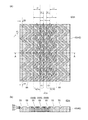
図12は、変形例2に係る燃料電池用ガス供給拡散層42bの平面構造を説明するために示す図である。図12において、符号R4は後述する「分割重なり領域」を示す。変形例2に係る燃料電池用ガス供給拡散層42bは、基本的には、実施形態に係る燃料電池用ガス供給拡散層42と同様の構成を有するが、ガス流路用溝に加えてガス圧均等化用溝が形成されている点が実施形態に係る燃料電池用ガス供給拡散層42の場合と異なる。すなわち、変形例2に係る燃料電池用ガス供給拡散層42bにおいては、図12に示すように、多孔質体層40には、複数のガス流路用溝55と交差するように、ガスの流入側から流出側に向かう方向に直交する幅方向全体にわたって、1本のガス圧均等化用溝56が形成されている。また、当該ガス圧均等化用溝56によって分割された重なり領域を「分割重なり領域R4」と定義したとき、分割重なり領域R4が、複数のガス流路用溝55のどの深さ位置においても存在する。変形例2に係る燃料電池用ガス供給拡散層42bによれば、ガス圧均等化用溝56の作用により、ガスの流入側から流出側に向かう方向に直交する幅方向全体にわたって燃料電池用ガスの供給量を均等にできる。また、分割重なり領域R4が、複数のガス流路用溝のどの深さ位置においても存在することから、多孔質体層に供給される燃料電池用ガスの供給経路が隙間無く分散するため、燃料電池用ガスを膜電極接合体に対してより一層均一に供給できる。[Modification 2]
FIG. 12 is a diagram shown for explaining the planar structure of the fuel cell gas supply /
なお、変形例2に係る燃料電池用ガス供給拡散層42bにおいては、ガス流路用溝55の深さと、ガス圧均等化用溝56の深さを等しくしている。このためガス流路用溝55とガス圧均等化用溝56とを同じ製造工程でかつ単純な構造の金型を用いて形成することが可能となることから、ガス圧均等化用溝を形成することによる製造コストの上昇を抑制できるという効果をも有する。
In the fuel cell gas supply /
[変形例3]
図13は、変形例3に係る燃料電池用ガス供給拡散層42cの平面構造を説明するために示す図である。変形例3に係る燃料電池用ガス供給拡散層42cは、基本的には、変形例2に係る燃料電池用ガス供給拡散層42bと同様の構成を有するが、ガス流路用溝55の構成が変形例2に係る燃料電池用ガス供給拡散層42cの場合と異なる。すなわち、変形例3に係る燃料電池用ガス供給拡散層42cにおいては、図13に示すように、ガス流路用溝55が、ガス流路用溝55の流入側端部の幅W1とガス流路用溝55の流出側端部の幅W2とが「W2<W1」の関係を満たすような構成を有する。変形例3に係る燃料電池用ガス供給拡散層42cによれば、ガス流路用溝中のガス流の線速度が流出端部側で高くなることから、流路間の多孔質中のガスの伏流割合が高くなり、多量の燃料電池用ガスをより一層均等に多孔質体層の全領域に送り込むことが可能となり、流出側の領域においても、いわゆる伏流領域での燃料電池用ガス濃度の低下を抑制することができる。また、反応生成物として生じ下流に向かって増加する水蒸気又は凝縮水を効果的に排出できる。流路用溝55の幅Wは、ガスの流入側から流出側に向かって徐々に狭くなっているが、段階的に狭くなっていてもよい。[Modification 3]
FIG. 13 is a diagram shown for explaining the planar structure of the fuel cell gas supply /
[変形例4]
図14は、変形例4に係る燃料電池用ガス供給拡散層42dの平面構造を説明するために示す図である。変形例4に係る燃料電池用ガス供給拡散層42dは、基本的には、変形例2に係る燃料電池用ガス供給拡散層42bと同様の構成を有するが、ガス流路用溝55の平面構造が変形例2に係る燃料電池用ガス供給拡散層42bの場合と異なる。すなわち、変形例4に係る燃料電池用ガス供給拡散層42dは、図14に示すように、流出側端部におけるガス流路用溝55の形成密度(単位面積当たりの形成本数)が流入側端部におけるガス流路用溝55の形成密度(単位面積当たりの形成本数)よりも高い。変形例4に係る燃料電池用ガス供給拡散層42dによれば、反応の進行に伴い燃料電池用ガスが下流に向かって流れるに従って消費されるために供給が少なくなりがちな流出側においても伏流領域における燃料電池用ガス濃度の低下を抑制することができ、また、反応生成物として生じ下流に向かって増加する水蒸気又は凝縮水を効果的に排出できる。[Modification example 4]
FIG. 14 is a diagram shown for explaining the planar structure of the fuel cell gas supply /
[変形例5]
図15は、変形例5に係る燃料電池用ガス供給拡散層42eの平面構造を説明するために示す図である。変形例5に係る燃料電池用ガス供給拡散層42eは、基本的には、変形例2に係る燃料電池用ガス供給拡散層42bと同様の構成を有するが、ガス流路用溝55の平面構造が変形例2に係る燃料電池用ガス供給拡散層42bの場合と異なる。すなわち、変形例5に係る燃料電池用ガス供給拡散層42eは、図15に示すように、変形例4の場合と同様に、流出側端部におけるガス流路用溝55の形成密度(単位面積当たりの形成本数)が流入側端部におけるガス流路用溝55の形成密度(単位面積当たりの形成本数)よりも高い。変形例5に係る燃料電池用ガス供給拡散層42dによれば、反応の進行に伴い燃料電池用ガスが下流に向かって流れるに従って消費されるために供給が少なくなりがちな流出側においても伏流領域における燃料電池用ガス濃度の低下を抑制することができ、また、反応生成物として生じ下流に向かって増加する水蒸気又は凝縮水を効果的に排出できる。なお、変形例5においては、変形例4においてよりもガス流路用溝55の縦方向のジグザグピッチを短くしている。[Modification 5]
FIG. 15 is a diagram shown for explaining the planar structure of the gas supply /
[変形例6]
図16は、変形例6に係る燃料電池用ガス供給拡散層42fの平面構造を説明するために示す図である。変形例6に係る燃料電池用ガス供給拡散層42fは、基本的には、変形例2〜5に係る燃料電池用ガス供給拡散層42b〜42eと同様の構成を有するが、ガス圧均等化用溝56の形成本数が、変形例2〜5に係る燃料電池用ガス供給拡散層42b〜42eの場合と異なる。すなわち、変形例6に係る燃料電池用ガス供給拡散層42fにおいては、図16に示すように、ガス圧均等化用溝56の形成本数が2本である。変形例6に係る燃料電池用ガス供給拡散層42fにおいては、ガス圧均等化用溝56の形成本数が2本であることから、ガス圧均等化用溝56の作用により、ガスの流入側から流出側に向かう方向に直交する幅方向全体にわたって燃料電池用ガスの供給量をより一層均等にできる。流路用溝55の幅Wは、ガスの流入側から流出側に向かって段階的に狭くなっているが、徐々に狭くなっていてもよい。[Modification 6]
FIG. 16 is a diagram shown for explaining the planar structure of the fuel cell gas supply /
[変形例7]
図17は、変形例7に係る燃料電池用ガス供給拡散層42gの平面構造を説明するために示す図である。変形例7に係る燃料電池用ガス供給拡散層42gは、基本的には、実施形態に係る燃料電池用ガス供給拡散層42と同様の構成を有するが、最も流入側にあるガス流路用溝の形成角度が、実施形態に係る燃料電池用ガス供給拡散層42の場合と異なる。すなわち、変形例7に係る燃料電池用ガス供給拡散層42gにおいては、図17に示すように、最も流入側にあるガス流路用溝55の形成角度が、燃料電池用ガスが当該ガス流路用溝55に入り易い角度になっている。変形例7に係る燃料電池用ガス供給拡散層42gによれば、最も流入側にあるガス流路用溝55の形成角度が、当該燃料電池用ガスがガス流路用溝55に入り易い角度になっていることから、燃料電池用ガスの移動抵抗が減少し、膜電極接合体に対してより一層多量の燃料電池用ガスを供給できる。[Modification 7]
FIG. 17 is a diagram shown for explaining the planar structure of the fuel cell gas supply /
[変形例8]
図18は、変形例8に係る燃料電池用ガス供給拡散層42hの平面構造を説明するために示す図である。変形例8に係る燃料電池用ガス供給拡散層42hは、基本的には、実施形態に係る燃料電池用ガス供給拡散層42と同様の構成を有するが、ガス流路用溝55の流入側端部と流出側端部の形成角度が、実施形態に係る燃料電池用ガス供給拡散層42の場合と異なる。すなわち、変形例8に係る燃料電池用ガス供給拡散層42hにおいては、図18に示すように、ガス流路用溝55の流入側端部と流出側端部の形成角度のいずれもが、ガスの流入側から流出側に沿う方向(金属板30の縦長方向)に平行となる角度になっている。変形例8に係る燃料電池用ガス供給拡散層42hによれば、ガス流路用溝55の流入側端部と流出側端部の形成角度のいずれもが、ガスの流入側から流出側に沿う方向(金属板30の縦長方向)に平行となる角度になっていることから、燃料電池用ガスの流入の際及び流出の際の流入の際の移動抵抗が減少し、膜電極接合体に対してより一層多量の燃料電池用ガスを供給できる。[Modification 8]
FIG. 18 is a diagram shown for explaining the planar structure of the fuel cell gas supply /
[変形例9]
図19は、変形例9に係る燃料電池用ガス供給拡散層42iの平面構造を説明するために示す図である。変形例9に係る燃料電池用ガス供給拡散層42iは、基本的には、変形例8に係る燃料電池用ガス供給拡散層42hと同様の構成を有するが、ガス流路用溝55の流入側端部と流出側端部の形成幅が変形例8に係る燃料電池用ガス供給拡散層42hの場合と異なる。すなわち、変形例9に係る燃料電池用ガス供給拡散層42iにおいては、図19に示すように、ガス流路用溝55の流入側端部と流出側端部の形成幅が変形例8に係る燃料電池用ガス供給拡散層42hの場合よりも広い。また、端部に向かうにつれて広くなるようなテーパー状になっている。変形例9に係る燃料電池用ガス供給拡散層42iによれば、ガス流路用溝55の流入側端部と流出側端部の形成幅が変形例8に係る燃料電池用ガス供給拡散層42hの場合よりも広く、また、端部に向かうにつれて広くなるようなテーパー状になっていることから、燃料電池用ガスの流入の際及び流出の際の移動抵抗がより一層減少し、膜電極接合体に対してより一層多量の燃料電池用ガスを供給できる。[Modification 9]
FIG. 19 is a diagram shown for explaining the planar structure of the fuel cell gas
[変形例10]
図20は、変形例10に係る燃料電池用ガス供給拡散層42jの平面構造を説明するために示す図である。変形例10に係る燃料電池用ガス供給拡散層42jは、基本的には、実施形態に係る係る燃料電池用ガス供給拡散層42と同様の構成を有するが、ガス流路用溝55の平面形状が実施形態に係る燃料電池用ガス供給拡散層42の場合と異なる。すなわち、変形例10に係る燃料電池用ガス供給拡散層42jにおいては、図20に示すように、複数のガス流路用溝55の平面形状が波状である。変形例10に係る燃料電池用ガス供給拡散層42jによれば、ガス流路用溝55の平面形状が実施形態に係る燃料電池用ガス供給拡散層42の場合とは異なるが、実施形態に係る燃料電池用ガス供給拡散層42の場合と同様に、多孔質体層に供給される燃料電池用ガスの供給経路が面内に広く分散するようになるため、複数のガス流路用溝がガスの流入側から流出側に向かって直線状に形成されている場合よりも燃料電池用ガスを膜電極接合体に対して均一に供給できる。[Modification 10]
FIG. 20 is a diagram shown for explaining the planar structure of the fuel cell gas supply /
[変形例11]
図21は、変形例11に係る燃料電池用セパレータ23kの平面構造を説明するために示す図である。変形例11に係る燃料電池用セパレータ23kはCタイプの燃料電池用セパレータであって、基本的には、実施形態に係る係る燃料電池用セパレータ23と同様の構成を有するが、カソードガス流入口62A及びカソードガス流出口62B、アノードガス流入口61A及びアノードガス流出口61B、並びに、冷却水流入口63A及び冷却水流出口63Bを含む平面構造が実施形態に係る燃料電池用セパレータ23の場合と異なる。すなわち、変形例11に係る燃料電池用セパレータ23kにおいては、図21に示すように、金属板30の縦方向両端部にそれぞれカソードガス流入口62A及びカソードガス流出口62Bのみが形成され、アノードガス流入口61A及びアノードガス流出口61B並びに冷却水流入口63A及び冷却水流出口63Bは、金属板30の横方向両端部にそれぞれ形成されている。変形例11に係る燃料電池用セパレータ23kによれば、アノードガスよりも燃料電池用ガス供給拡散層中を拡散し難いカソードガスを流通させるためのカソードガス流入口62A及びカソードガス流出口62Bの形成幅を広くできることから、より一層多量のカソードガスを膜電極接合体に対して均一に供給できる。また、発電に使用されなかった酸素ガス及び窒素ガスをガス流路用溝外に効率良く排出できるようになるため、燃料電池の発電効率をより一層高くできる、燃料電池用ガス供給拡散層となる。また、変形例11に係る燃料電池用ガス供給拡散層23kによれば、発電時に膜電極接合体で生成した水蒸気又は凝縮水をガス流路用溝外に効率良く排出できるようになるため、より一層排水性に優れた燃料電池用ガス供給拡散層となる。[Modification 11]
FIG. 21 is a diagram shown for explaining the planar structure of the
[変形例12]
上記した実施形態においては、膜電極接合体として、燃料電池用ガス供給拡散層42,41とほぼ同じ面積の触媒層85を有する膜電極接合体81を用いたが、本発明はこれに限定されるものではない。膜電極接合体として、燃料電池用ガス供給拡散層42,41よりも小さい面積の触媒層85を有する膜電極接合体を用いてもよい。図22は、変形例12に係る燃料電池用セパレータ23Lの平面図である。変形例12に係る燃料電池用セパレータ23Lにおいては、膜電極接合体81として、燃料電池用ガス供給拡散層42,41よりも小さい面積の触媒層85を有する膜電極接合体を用いるとともに、燃料電池用ガス供給拡散層42,41の中央部分(燃料電池用ガス供給拡散層42,41の膜電極接合体81側の表面にカソードガスが均一に供給される部分)に膜電極接合体81の触媒層85が位置するようにこれらを積層したものである。変形例12に係る燃料電池用セパレータ23Lによれば、燃料電池用ガスが均一に供給され発電効率のよい領域で発電を行うことができるようになり燃料電池の発電効率をより一層高くできる。[Modification 12]
In the above-described embodiment, the
[変形例13]
上記した実施形態においては、ガス流路用溝として、多孔質体層40(又はガス流路用溝55)の表面のガス流路用溝の幅と、ガス流路用溝55の底のガス流路用溝の幅とが等しく、断面が長方形状のガス流路用溝55を用いたが(図5及び図7参照。)、本発明はこれに限定されるものではない。溝の底が表面よりも狭い断面三角形状のガス流路用溝であってもよいし、溝の底が表面よりも狭い断面半円形状のガス流路用溝であってもよいし、その他の形状のガス流路用溝であってもよい。図23及び図24は、変形例13に係るガス流路用溝55の形成パターンを説明するために示す図である。このうち、図23はガス流路用溝55の構造を示す図であり、図24は、異なる深さ位置におけるガス流路用溝55の平面構造を説明するために示す図である。図23(a)は平面図であり、図23(b)は図23(a)のA−A断面図である。図24(a)は深さ位置D1(多孔質体層40(又はガス流路用溝55)の表面における深さ位置)におけるガス流路用溝55の平面構造を示し、図24(b)は深さ位置D2(ガス流路用溝55の深さの1/2の深さ位置)におけるガス流路用溝55の平面構造を示し、図24(c)は深さ位置D3(ガス流路用溝55の底における深さ位置)におけるガス流路用溝55の平面構造を示す。図23及び図24においては、カソードガスの流れを図示している。図23(a)及び図24中、ガス流路用溝55内の矢印はガス流路用溝55に沿った流れであり、多孔質体層40内に記した縦方向上向きの矢印はガス流路用溝55から多孔質体層40(ガス拡散層43)中に押し出されたカソードガスの流れ(伏流ガス流れ)である。また、図24(b)中、多孔質体40内に記した横方向及び下方向(膜電極接合体側に向かう方向)向きの矢印は、ガス流路用溝55mから膜電極接合体側に向けて多孔質体層40(ガス拡散層43)中に押し出されたカソードガスの流れを示す。[Modification 13]
In the above-described embodiment, as the gas flow path groove, the width of the gas flow path groove on the surface of the porous body layer 40 (or the gas flow path groove 55) and the gas at the bottom of the gas
図23に示すように、ガス流路用溝として、溝の底が表面よりも狭い断面三角形状のガス流路用溝55を用いることもできる。このような場合には、深さ位置D3における矩形領域Rの面積が深さ位置D1における矩形領域Rの面積よりも小さくなり、燃料電池用ガスを膜電極接合体に対して均一に供給するという観点では不利になるが、このような場合であっても、図24に示すように、第1矩形領域R1と第2矩形領域R2とが重なる重なり領域R3が、複数のガス流路用溝55のどの深さ位置においても存在するようにすれば、実施形態に係る燃料電池用ガス供給拡散層42の場合と同様に、燃料電池用ガスを膜電極接合体に対してより一層均一に供給できる。従って、本発明の燃料電池用ガス供給拡散層が有する「燃料電池用ガスを膜電極接合体に対してより一層均一に供給できる」という効果は、重なる重なり領域R3が、複数のガス流路用溝55のどの深さ位置においても存在するという条件を満たしている場合には、ガス流路用溝55の断面形状を問わず得られるものである。
As shown in FIG. 23, as the gas flow path groove, a gas flow path groove 55 having a triangular cross section whose bottom is narrower than the surface can also be used. In such a case, the area of the rectangular region R at the depth position D3 becomes smaller than the area of the rectangular region R at the depth position D1, and the fuel cell gas is uniformly supplied to the membrane electrode assembly. Although it is disadvantageous from the viewpoint, even in such a case, as shown in FIG. 24, the overlapping region R3 in which the first rectangular region R1 and the second rectangular region R2 overlap is the plurality of gas
[変形例14]
上記した実施形態においては、燃料電池用ガス供給拡散層として、一方の面にガス流路用溝55が形成された多孔質体層40を備える燃料電池用ガス供給拡散層42を用いたが(図5参照。)、本発明はこれに限定されるものではない。図25は、変形例14に係る燃料電池用ガス供給拡散層42nの断面図である。図5の場合と同様に、膜電極接合体81が接合された状態の燃料電池用セパレータ23nを示している。図25に示すように、一方の面にガス流路用溝55が形成された多孔質体層40と、当該多孔質体層40の他方の面に配設されたマイクロポーラスレイヤ44とを備える燃料電池用ガス供給拡散層を用いこともできる。このような構成とした場合には、マイクロポーラスレイヤを備えない膜電極接合体を用いて燃料電池用セパレータを構成することができるようになる。[Modification 14]
In the above-described embodiment, as the fuel cell gas supply / diffusion layer, a fuel cell gas supply /
[変形例15]
上記した実施形態においては、ガス遮蔽板として、金属板30を用いたが、本発明はこれに限定されるものではない。金属板30以外の、ガスを遮蔽する性質をもった材料からなる板(例えば、セラミックス板、樹脂板)を用いることもできる。[Modification 15]
In the above-described embodiment, the
なお、上記各変形例は、各変形例に記載の特徴を、実施形態に係る燃料電池用ガス供給拡散層42、燃料電池用セパレータ23及び燃料電池セルスタック20に適用したものであるが、各変形例に記載の特徴は、これに限らず、本発明の燃料電池用ガス供給拡散層、燃料電池用セパレータ及び燃料電池セルスタックの全般に適用可能である。例えば、各変形例に記載の特徴は、タイプCAの燃料電池用ガス供給拡散層21、タイプCWの燃料電池用ガス供給拡散層24、タイプAの燃料電池用ガス供給拡散層22、タイプAWの燃料電池用ガス供給拡散層25、これら燃料電池用ガス供給拡散層を備えた燃料電池用セパレータ及び燃料電池セルスタックにも適用可能である。
In each of the above-mentioned modifications, the features described in each of the modifications are applied to the fuel cell gas
以上、本発明の燃料電池用ガス供給拡散層、燃料電池用セパレータ及び燃料電池セルスタックを、図示の実施の形態に基づいて説明したが、本発明は上記の各実施形態に限られるものではなく、本発明の要旨を逸脱しない範囲で種々変形実施可能となるものである。 The gas supply diffusion layer for a fuel cell, the separator for a fuel cell, and the fuel cell stack of the present invention have been described above based on the illustrated embodiments, but the present invention is not limited to the above embodiments. , Various modifications can be carried out without departing from the gist of the present invention.
20 燃料電池セルスタック、21,22,23,23a〜23k,23L,23m,23n,24,25 燃料電池用セパレータ、27A,27B 集電板、28A,28B 絶縁シート、30 金属板、32 緻密枠、33 ガスケット、33A ガスケット用溝、40 多孔質体層、41 燃料電池用ガス供給拡散層(アノードガス供給拡散層)、42,42a〜42k,42m,42n 燃料電池用ガス供給拡散層(カソードガス供給拡散層)、43 ガス拡散層、44 マイクロポーラスレイヤ、45 冷却水供給拡散層、46 冷却水流路、51 流入側溝、52 流出側溝、55 ガス流路用溝、55A 一のガス流路用溝、55B 一のガス流路用溝55Aに隣接するガス流路用溝、56 ガス圧均等化用層、57 流入通路、58 流出通路、61A アノードガス流入口、61B アノードガス流出口、62A カソードガス流入口、62B カソードガス流出口、63A 冷却水流入口、63B 冷却水流出口、74 締め付け・バネサポート、75,76 エンドプレート、80 セル構造体、81 膜電極接合体、81A 枠(フレーム)、82 電解質膜、83 マイクロポーラスレイヤー、85 触媒層、D1 多孔質体層40の表面(又はガス流路用溝55の表面)における深さ位置、D2 ガス流路用溝55の深さの1/2の深さ位置、D3 ガス流路用溝55の底における深さ位置、L 矩形領域の幅、L1 重なり領域R3の幅、L2 ガス流路用溝55(矩形領域R)の配列ピッチ、R 矩形領域、R1 第1矩形領域、R2 第2矩形領域、R3 重なり領域、R4 分割重なり領域、W ガス流路用溝55の幅(ガス流路用溝55内におけるガスの流れに直交する方向に沿った幅)、W1 ガス流路用溝55の流入側端部の幅、W2 ガス流路用溝55の流出側端部の幅
20 Fuel cell stack, 21,22,23,23a-23k, 23L, 23m, 23n, 24,25 Fuel cell separator, 27A, 27B current collector, 28A, 28B insulation sheet, 30 metal plate, 32 dense frame , 33 gasket, 33A gasket groove, 40 porous body layer, 41 fuel cell gas supply diffusion layer (anodic gas supply diffusion layer), 42, 42a to 42k, 42m, 42n fuel cell gas supply diffusion layer (cathode gas) Supply diffusion layer), 43 gas diffusion layer, 44 microporous layer, 45 cooling water supply diffusion layer, 46 cooling water flow path, 51 inflow side groove, 52 outflow side groove, 55 gas flow path groove, 55A one gas flow path groove , 55B One gas flow path groove 55A adjacent gas flow path groove, 56 gas pressure equalization layer, 57 inflow passage, 58 outflow passage, 61A anode gas inlet, 61B anode gas outlet, 62A cathode gas Inlet, 62B cathode gas outlet, 63A cooling water inlet, 63B cooling water outlet, 74 tightening / spring support, 75,76 end plate, 80 cell structure, 81 film electrode junction, 81A frame, 82 electrolyte The depth position on the surface of the membrane, 83 microporous layer, 85 catalyst layer, D1 porous body layer 40 (or the surface of the gas flow path groove 55), 1/2 of the depth of the D2 gas flow path groove 55. Depth position, depth position at the bottom of the D3 gas
Claims (19)
ガスの透過及び拡散が可能で、かつ、導電性を有するシート状の多孔質体層と、
前記多孔質体層の一方の面において並列に、かつ、それぞれが前記ガスの流入側から流出側に向かってジグザグ状又は波状に形成された複数のガス流路用溝とを有し、
平面的に見て、前記複数のガス流路用溝のうちそれぞれのガス流路用溝が外接する複数の矩形領域Rのうち、一のガス流路用溝が外接する第1矩形領域R1と、前記一のガス流路用溝に隣接するガス流路用溝が外接する第2矩形領域R2とがその接する領域に沿って重なっており、かつ、前記第1矩形領域R1と前記第2矩形領域R2とが重なる重なり領域R3が、前記複数のガス流路用溝の断面形状を問わず前記複数のガス流路用溝のどの深さ位置においても存在し、
前記多孔質体層には、前記複数のガス流路用溝と交差するように、前記ガスの流入側から流出側に向かう方向に直交する幅方向全体にわたって、1又は複数のガス圧均等化用溝が形成され、
前記のガス圧均等化用溝によって分割された前記重なり領域を「分割重なり領域R4」と定義したとき、前記分割重なり領域R4は、前記複数のガス流路用溝の断面形状を問わず前記複数のガス流路用溝のどの深さ位置においても存在することを特徴とする燃料電池用ガス供給拡散層。 A gas supply diffusion layer for fuel cells
A sheet-like porous body layer capable of permeating and diffusing gas and having conductivity,
It has a plurality of gas flow path grooves formed in parallel on one surface of the porous body layer and in a zigzag shape or a wavy shape from the inflow side to the outflow side of the gas.
When viewed in a plane, among the plurality of rectangular regions R to which each of the plurality of gas flow path grooves circumscribes, the first rectangular region R1 to which one gas flow path groove circumscribes. The second rectangular region R2 circumscribing the gas flow path groove adjacent to the one gas flow path groove overlaps along the circumscribing region, and the first rectangular region R1 and the second rectangular region R1 overlap. An overlapping region R3 that overlaps with the region R2 exists at any depth position of the plurality of gas flow path grooves regardless of the cross-sectional shape of the plurality of gas flow path grooves.
The porous body layer is used for equalizing one or more gas pressures over the entire width direction orthogonal to the direction from the inflow side to the outflow side of the gas so as to intersect the plurality of gas flow path grooves. Grooves are formed,
When the overlapping region divided by the gas pressure equalizing groove is defined as the "divided overlapping region R4", the divided overlapping region R4 is the plurality of the overlapping regions R4 regardless of the cross-sectional shape of the plurality of gas flow path grooves. A gas supply / diffusion layer for a fuel cell , which is present at any depth of the gas flow path groove.
前記重なり領域R3の幅L1と、前記矩形領域の幅Lとは、「L1≧0.1×L」の関係を満たすことを特徴とする燃料電池用ガス供給拡散層。 In the gas supply / diffusion layer for a fuel cell according to claim 1.
A gas supply / diffusion layer for a fuel cell, characterized in that the width L1 of the overlapping region R3 and the width L of the rectangular region satisfy the relationship of “L1 ≧ 0.1 × L”.
前記ガス流路用溝の深さと、前記ガス圧均等化用溝の深さは等しいことを特徴とする燃料電池用ガス供給拡散層。 In the fuel cell gas supply diffusion layer according to claim 1 or 2.
A gas supply / diffusion layer for a fuel cell, characterized in that the depth of the gas flow path groove is equal to the depth of the gas pressure equalization groove.
前記多孔質体層の他方の面に配設されたマイクロポーラスレイヤをさらに備えることを特徴とする燃料電池用ガス供給拡散層。 In the fuel cell gas supply diffusion layer according to any one of claims 1 to 3.
A gas supply / diffusion layer for a fuel cell, further comprising a microporous layer disposed on the other surface of the porous body layer.
前記燃料電池用ガス供給拡散層が、カソードガス用の燃料電池用ガス供給拡散層であることを特徴とする燃料電池用ガス供給拡散層。 In the fuel cell gas supply diffusion layer according to any one of claims 1 to 4.
A fuel cell gas supply / diffusion layer, wherein the fuel cell gas supply / diffusion layer is a fuel cell gas supply / diffusion layer for cathode gas.
前記カソードガスが空気であることを特徴とする燃料電池用ガス供給拡散層。 In the gas supply diffusion layer for a fuel cell according to claim 5.
A gas supply / diffusion layer for a fuel cell, wherein the cathode gas is air.
前記ガス流路用溝の流入側端部の幅W1と、前記ガス流路用溝の流出側端部の幅W2とは、「W2<W1」の関係を満たすことを特徴とする燃料電池用ガス供給拡散層。 In the fuel cell gas supply diffusion layer according to claim 5 or 6.
The width W1 of the inflow side end of the gas flow path groove and the width W2 of the outflow side end of the gas flow path groove satisfy the relationship of "W2 <W1" for a fuel cell. Gas supply diffusion layer.
流出側端部における前記ガス流路用溝の形成密度は、流入側端部における前記ガス流路用溝の形成密度よりも高いことを特徴とする燃料電池用ガス供給拡散層。 In the fuel cell gas supply diffusion layer according to any one of claims 5 to 7.
The gas supply / diffusion layer for a fuel cell, characterized in that the formation density of the gas flow path groove at the outflow side end is higher than the formation density of the gas flow path groove at the inflow side end.
ガスの透過及び拡散が可能で、かつ、導電性を有するシート状の多孔質体層と、
前記多孔質体層の一方の面において並列に、かつ、それぞれが前記ガスの流入側から流出側に向かってジグザグ状又は波状に形成された複数のガス流路用溝とを有し、
平面的に見て、前記複数のガス流路用溝のうちそれぞれのガス流路用溝が外接する複数の矩形領域Rのうち、一のガス流路用溝が外接する第1矩形領域R1と、前記一のガス流路用溝に隣接するガス流路用溝が外接する第2矩形領域R2とがその接する領域に沿って重なっており、かつ、前記第1矩形領域R1と前記第2矩形領域R2とが重なる重なり領域R3が、前記複数のガス流路用溝の断面形状を問わず前記複数のガス流路用溝のどの深さ位置においても存在し、
前記燃料電池用ガス供給拡散層が、カソードガス用の燃料電池用ガス供給拡散層であり、
前記ガス流路用溝の流入側端部の幅W1と、前記ガス流路用溝の流出側端部の幅W2とは、「W2<W1」の関係を満たすことを特徴とする燃料電池用ガス供給拡散層。 A gas supply diffusion layer for fuel cells
A sheet-like porous body layer capable of permeating and diffusing gas and having conductivity,
It has a plurality of gas flow path grooves formed in parallel on one surface of the porous body layer and in a zigzag shape or a wavy shape from the inflow side to the outflow side of the gas.
When viewed in a plane, among the plurality of rectangular regions R to which each of the plurality of gas flow path grooves circumscribes, the first rectangular region R1 to which one gas flow path groove circumscribes. The second rectangular region R2 circumscribing the gas flow path groove adjacent to the one gas flow path groove overlaps along the circumscribing region, and the first rectangular region R1 and the second rectangular region R1 overlap. An overlapping region R3 that overlaps with the region R2 exists at any depth position of the plurality of gas flow path grooves regardless of the cross-sectional shape of the plurality of gas flow path grooves.
The fuel cell gas supply / diffusion layer is a fuel cell gas supply / diffusion layer for cathode gas.
The width W1 of the inflow side end of the gas flow path groove and the width W2 of the outflow side end of the gas flow path groove satisfy the relationship of "W2 <W1" for a fuel cell. Gas supply diffusion layer.
前記カソードガスが空気であることを特徴とする燃料電池用ガス供給拡散層。 In the gas supply diffusion layer for a fuel cell according to claim 9.
A gas supply / diffusion layer for a fuel cell, wherein the cathode gas is air.
流出側端部における前記ガス流路用溝の形成密度は、流入側端部における前記ガス流路用溝の形成密度よりも高いことを特徴とする燃料電池用ガス供給拡散層。 In the fuel cell gas supply diffusion layer according to claim 9 or 10.
The gas supply / diffusion layer for a fuel cell, characterized in that the formation density of the gas flow path groove at the outflow side end is higher than the formation density of the gas flow path groove at the inflow side end.
前記重なり領域R3の幅L1と、前記矩形領域の幅Lとは、「L1≧0.1×L」の関係を満たすことを特徴とする燃料電池用ガス供給拡散層。 In the fuel cell gas supply diffusion layer according to any one of claims 9 to 11.
A gas supply / diffusion layer for a fuel cell, characterized in that the width L1 of the overlapping region R3 and the width L of the rectangular region satisfy the relationship of “L1 ≧ 0.1 × L”.
前記多孔質体層の他方の面に配設されたマイクロポーラスレイヤをさらに備えることを特徴とする燃料電池用ガス供給拡散層。 In the fuel cell gas supply diffusion layer according to any one of claims 9 to 12.
A gas supply / diffusion layer for a fuel cell, further comprising a microporous layer disposed on the other surface of the porous body layer.
ガスの透過及び拡散が可能で、かつ、導電性を有するシート状の多孔質体層と、
前記多孔質体層の一方の面において並列に、かつ、それぞれが前記ガスの流入側から流出側に向かってジグザグ状又は波状に形成された複数のガス流路用溝とを有し、
平面的に見て、前記複数のガス流路用溝のうちそれぞれのガス流路用溝が外接する複数の矩形領域Rのうち、一のガス流路用溝が外接する第1矩形領域R1と、前記一のガス流路用溝に隣接するガス流路用溝が外接する第2矩形領域R2とがその接する領域に沿って重なっており、かつ、前記第1矩形領域R1と前記第2矩形領域R2とが重なる重なり領域R3が、前記複数のガス流路用溝の断面形状を問わず前記複数のガス流路用溝のどの深さ位置においても存在し、
前記燃料電池用ガス供給拡散層が、カソードガス用の燃料電池用ガス供給拡散層であり、
流出側端部における前記ガス流路用溝の形成密度は、流入側端部における前記ガス流路用溝の形成密度よりも高いことを特徴とする燃料電池用ガス供給拡散層。 A gas supply diffusion layer for fuel cells
A sheet-like porous body layer capable of permeating and diffusing gas and having conductivity,
It has a plurality of gas flow path grooves formed in parallel on one surface of the porous body layer and in a zigzag shape or a wavy shape from the inflow side to the outflow side of the gas.
When viewed in a plane, among the plurality of rectangular regions R to which each of the plurality of gas flow path grooves circumscribes, the first rectangular region R1 to which one gas flow path groove circumscribes. The second rectangular region R2 circumscribing the gas flow path groove adjacent to the one gas flow path groove overlaps along the circumscribing region, and the first rectangular region R1 and the second rectangular region R1 overlap. An overlapping region R3 that overlaps with the region R2 exists at any depth position of the plurality of gas flow path grooves regardless of the cross-sectional shape of the plurality of gas flow path grooves.
The fuel cell gas supply / diffusion layer is a fuel cell gas supply / diffusion layer for cathode gas.
The gas supply / diffusion layer for a fuel cell , characterized in that the formation density of the gas flow path groove at the outflow side end is higher than the formation density of the gas flow path groove at the inflow side end.
前記カソードガスが空気であることを特徴とする燃料電池用ガス供給拡散層。 In the gas supply diffusion layer for a fuel cell according to claim 14.
A gas supply / diffusion layer for a fuel cell, wherein the cathode gas is air.
前記重なり領域R3の幅L1と、前記矩形領域の幅Lとは、「L1≧0.1×L」の関係を満たすことを特徴とする燃料電池用ガス供給拡散層。 In the fuel cell gas supply diffusion layer according to claim 14 or 15.
A gas supply / diffusion layer for a fuel cell, characterized in that the width L1 of the overlapping region R3 and the width L of the rectangular region satisfy the relationship of “L1 ≧ 0.1 × L”.
前記多孔質体層の他方の面に配設されたマイクロポーラスレイヤをさらに備えることを特徴とする燃料電池用ガス供給拡散層。 In the fuel cell gas supply diffusion layer according to any one of claims 14 to 16.
A gas supply / diffusion layer for a fuel cell, further comprising a microporous layer disposed on the other surface of the porous body layer.
前記ガス遮蔽板の少なくとも一方の面に配設された燃料電池用ガス供給拡散層とを備える燃料電池用セパレータであって、
前記燃料電池用ガス供給拡散層は、請求項1〜17のいずれかに記載の燃料電池用ガス供給拡散層であり、
前記燃料電池用ガス供給拡散層は、前記複数のガス流路用溝が前記ガス遮蔽板側に位置するように前記ガス遮蔽板に対して配置されており、
前記ガス流路用溝と前記ガス遮蔽板とでガス流路が構成されていることを特徴とする燃料電池用セパレータ。 Gas shield and
A fuel cell separator provided with a fuel cell gas supply / diffusion layer disposed on at least one surface of the gas shielding plate.
The fuel cell gas supply / diffusion layer is the fuel cell gas supply / diffusion layer according to any one of claims 1 to 17.
The gas supply / diffusion layer for a fuel cell is arranged with respect to the gas shielding plate so that the plurality of gas flow path grooves are located on the gas shielding plate side.
A fuel cell separator characterized in that the gas flow path is formed by the gas flow path groove and the gas shielding plate.
前記燃料電池用セパレータは、請求項18に記載の燃料電池用セパレータであり、
前記燃料電池用セパレータと前記膜電極接合体とは、前記燃料電池用ガス供給拡散層の前記複数のガス流路用溝が形成されていない側の面に前記膜電極接合体が位置する位置関係で積層されていることを特徴とする燃料電池セルスタック。 A fuel cell stack in which a fuel cell separator and a membrane electrode assembly are laminated.
The fuel cell separator is the fuel cell separator according to claim 18 .
The fuel cell separator and the membrane electrode assembly have a positional relationship in which the membrane electrode assembly is located on the surface of the fuel cell gas supply diffusion layer on the side where the plurality of gas flow path grooves are not formed. A fuel cell stack characterized by being laminated in.
Applications Claiming Priority (1)
| Application Number | Priority Date | Filing Date | Title |
|---|---|---|---|
| PCT/JP2018/017353 WO2019207811A1 (en) | 2018-04-28 | 2018-04-28 | Fuel cell gas feed diffusion layer, fuel cell separator, and fuel cell stack |
Publications (2)
| Publication Number | Publication Date |
|---|---|
| JPWO2019207811A1 JPWO2019207811A1 (en) | 2020-12-03 |
| JP6876197B2 true JP6876197B2 (en) | 2021-05-26 |
Family
ID=68295229
Family Applications (1)
| Application Number | Title | Priority Date | Filing Date |
|---|---|---|---|
| JP2020515996A Active JP6876197B2 (en) | 2018-04-28 | 2018-04-28 | Fuel cell gas supply diffusion layer, fuel cell separator and fuel cell cell stack |
Country Status (6)
| Country | Link |
|---|---|
| US (1) | US11670780B2 (en) |
| EP (1) | EP3790088A4 (en) |
| JP (1) | JP6876197B2 (en) |
| KR (1) | KR102490771B1 (en) |
| CN (1) | CN111886731B (en) |
| WO (1) | WO2019207811A1 (en) |
Families Citing this family (1)
| Publication number | Priority date | Publication date | Assignee | Title |
|---|---|---|---|---|
| AU2020437485A1 (en) | 2020-03-26 | 2022-07-28 | Eh Group Engineering Ag | Fuel cell |
Family Cites Families (13)
| Publication number | Priority date | Publication date | Assignee | Title |
|---|---|---|---|---|
| JP4245091B2 (en) * | 1998-10-01 | 2009-03-25 | 本田技研工業株式会社 | Fuel cell |
| JP2004327358A (en) * | 2003-04-28 | 2004-11-18 | Nissan Motor Co Ltd | Polymer electrolyte fuel cell |
| KR100718113B1 (en) * | 2006-01-27 | 2007-05-15 | 삼성에스디아이 주식회사 | Bipolar plate for fuel cell and fuel cell |
| JP2007299656A (en) | 2006-04-28 | 2007-11-15 | Equos Research Co Ltd | Electrode of fuel cell |
| JP2008293811A (en) * | 2007-05-25 | 2008-12-04 | Toyota Motor Corp | Gas supply member of fuel cell, and fuel cell |
| EP2477262A4 (en) * | 2009-09-10 | 2017-07-12 | Panasonic Corporation | Gas diffusion layer and process for production thereof, and fuel cell |
| WO2011045889A1 (en) | 2009-10-13 | 2011-04-21 | パナソニック株式会社 | Fuel cell and method for manufacturing same |
| JP5902897B2 (en) * | 2011-07-12 | 2016-04-13 | 三菱レイヨン株式会社 | Gas diffusion electrode and fuel cell using the same |
| WO2015072584A1 (en) | 2013-11-18 | 2015-05-21 | 国立大学法人山梨大学 | Separator and cell stack for fuel cell |
| DE102014213555A1 (en) * | 2014-07-11 | 2016-01-14 | Sgl Carbon Se | Membrane-electrode assembly |
| JP6741917B2 (en) * | 2015-03-27 | 2020-08-19 | パナソニックIpマネジメント株式会社 | Fuel cell catalyst layer and fuel cell |
| KR101766098B1 (en) * | 2015-12-30 | 2017-08-08 | 현대자동차주식회사 | Porous panel for fuelcell |
| WO2018155220A1 (en) * | 2017-02-23 | 2018-08-30 | パナソニックIpマネジメント株式会社 | Membrane electrode assembly and fuel cell |
-
2018
- 2018-04-28 KR KR1020207030416A patent/KR102490771B1/en active IP Right Grant
- 2018-04-28 EP EP18916875.0A patent/EP3790088A4/en active Pending
- 2018-04-28 WO PCT/JP2018/017353 patent/WO2019207811A1/en unknown
- 2018-04-28 CN CN201880091648.0A patent/CN111886731B/en active Active
- 2018-04-28 JP JP2020515996A patent/JP6876197B2/en active Active
- 2018-04-28 US US17/049,871 patent/US11670780B2/en active Active
Also Published As
| Publication number | Publication date |
|---|---|
| CN111886731B (en) | 2023-06-16 |
| US20210242472A1 (en) | 2021-08-05 |
| EP3790088A4 (en) | 2021-12-15 |
| KR20200134294A (en) | 2020-12-01 |
| EP3790088A1 (en) | 2021-03-10 |
| CN111886731A (en) | 2020-11-03 |
| WO2019207811A1 (en) | 2019-10-31 |
| US11670780B2 (en) | 2023-06-06 |
| JPWO2019207811A1 (en) | 2020-12-03 |
| KR102490771B1 (en) | 2023-01-20 |
Similar Documents
| Publication | Publication Date | Title |
|---|---|---|
| JP6534015B2 (en) | Separator and cell stack for fuel cell | |
| US8304145B2 (en) | High tortuosity diffusion medium | |
| JP6573192B2 (en) | Separator, cell structure and cell stack for fuel cell | |
| JP2005276519A (en) | Solid polymer fuel cell | |
| JP7187346B2 (en) | Fuel cell and fuel cell stack | |
| JP6876197B2 (en) | Fuel cell gas supply diffusion layer, fuel cell separator and fuel cell cell stack | |
| WO2015004969A1 (en) | Fuel cell unit cell | |
| JP2016042463A (en) | Fuel cell improved in distribution of reactant | |
| JP7047090B2 (en) | Gas supply diffusion layer for fuel cells, separators for fuel cells and fuel cell stack | |
| US20220243348A1 (en) | COx ELECTROLYZER CELL FLOW FIELDS AND GAS DIFFUSION LAYERS | |
| JP2011192525A (en) | Fuel cell | |
| US20230332306A1 (en) | COx ELECTROLYZER CELL FLOW FIELDS AND GAS DIFFUSION LAYERS | |
| US20240120510A1 (en) | Gas diffusion layer, separator and electrochemical reactor | |
| US20230147601A1 (en) | Gas diffusion member, gas diffusion unit, and fuel cell | |
| CN112771700B (en) | Fluid guide channel and fuel cell provided with same | |
| JP7379481B2 (en) | Fuel cell with fluid guide channel and method for manufacturing the same | |
| JP2008123901A (en) | Fuel cell | |
| JP2017162750A (en) | Gas diffusion layer for fuel cell, and fuel cell | |
| US20110014538A1 (en) | Fuel cell | |
| US20110014537A1 (en) | Fuel cell | |
| JP2017174563A (en) | Fuel cell |
Legal Events
| Date | Code | Title | Description |
|---|---|---|---|
| A521 | Request for written amendment filed |
Free format text: JAPANESE INTERMEDIATE CODE: A523 Effective date: 20200430 |
|
| A621 | Written request for application examination |
Free format text: JAPANESE INTERMEDIATE CODE: A621 Effective date: 20200430 |
|
| A521 | Request for written amendment filed |
Free format text: JAPANESE INTERMEDIATE CODE: A523 Effective date: 20200817 |
|
| TRDD | Decision of grant or rejection written | ||
| A01 | Written decision to grant a patent or to grant a registration (utility model) |
Free format text: JAPANESE INTERMEDIATE CODE: A01 Effective date: 20210413 |
|
| A61 | First payment of annual fees (during grant procedure) |
Free format text: JAPANESE INTERMEDIATE CODE: A61 Effective date: 20210423 |
|
| R150 | Certificate of patent or registration of utility model |
Ref document number: 6876197 Country of ref document: JP Free format text: JAPANESE INTERMEDIATE CODE Ref document number: 6876197 Country of ref document: JP Free format text: JAPANESE INTERMEDIATE CODE: R150 |
|
| R250 | Receipt of annual fees |
Free format text: JAPANESE INTERMEDIATE CODE: R250 |