WO2019203056A1 - 画像処理装置、画像処理方法及びプログラム - Google Patents
画像処理装置、画像処理方法及びプログラム Download PDFInfo
- Publication number
- WO2019203056A1 WO2019203056A1 PCT/JP2019/015413 JP2019015413W WO2019203056A1 WO 2019203056 A1 WO2019203056 A1 WO 2019203056A1 JP 2019015413 W JP2019015413 W JP 2019015413W WO 2019203056 A1 WO2019203056 A1 WO 2019203056A1
- Authority
- WO
- WIPO (PCT)
- Prior art keywords
- image
- pole
- boundary line
- image processing
- blood vessel
- Prior art date
Links
Images


Classifications
-
- A—HUMAN NECESSITIES
- A61—MEDICAL OR VETERINARY SCIENCE; HYGIENE
- A61B—DIAGNOSIS; SURGERY; IDENTIFICATION
- A61B3/00—Apparatus for testing the eyes; Instruments for examining the eyes
- A61B3/10—Objective types, i.e. instruments for examining the eyes independent of the patients' perceptions or reactions
- A61B3/12—Objective types, i.e. instruments for examining the eyes independent of the patients' perceptions or reactions for looking at the eye fundus, e.g. ophthalmoscopes
Definitions
- the disclosed technology relates to an image processing apparatus, an image processing method, and a program.
- a tomographic imaging apparatus for the eye such as an optical coherence tomography (OCT)
- OCT optical coherence tomography
- This tomographic imaging apparatus is widely used in ophthalmic practice because it is useful for more accurately diagnosing diseases.
- OCT optical coherence tomography
- TD-OCT Time domain OCT
- a broadband light source and a Michelson interferometer are combined. This is configured to measure the interference light with the backscattered light acquired by the signal arm by moving the position of the reference mirror at a constant speed to obtain the reflected light intensity distribution in the depth direction.
- TD-OCT requires mechanical scanning, high-speed image acquisition is difficult.
- SS-OCT Single Source
- SD-OCT Spectral domain OCT
- fundus blood vessel images are used to grasp the pathology of the fundus blood vessels.
- OCT Angiography (hereinafter referred to as OCTA) technology for non-invasively drawing a fundus blood vessel in three dimensions using OCT has been used to create a fundus blood vessel image.
- OCT OCT Angiography
- the same position is scanned a plurality of times with measurement light, and the motion contrast obtained by the interaction between the displacement of red blood cells and the measurement light is imaged.
- OCTA imaging shows an example of OCTA imaging in which the main scanning direction is the horizontal (x-axis) direction and the B-scan is continuously performed r times at each position (yi; 1 ⁇ i ⁇ n) in the sub-scanning direction (y-axis direction). ing.
- OCTA imaging scanning a plurality of times at the same position is called cluster scanning, and a plurality of tomographic images obtained at the same position is called a cluster. It is known that when the motion contrast data is generated in cluster units and the number of tomographic images per cluster (the number of scans at substantially the same position) is increased, the contrast of the OCTA image is improved.
- an avascular region such as a foveal avascular region in a two-dimensional OCTA image and measurement of the area of the avascular region are performed. This is disclosed in Patent Document 1.
- the avascular region in the two-dimensional OCTA image is specified by performing a histogram analysis of the two-dimensional OCTA image.
- Pole determining means for determining the pole of the avascular region in the fundus blood vessel image of the eye to be examined;
- Coordinate conversion means for executing a coordinate conversion process for converting the fundus blood vessel image into a coordinate image different from the orthogonal coordinate image based on the determined pole;
- Boundary line determining means for determining a boundary line of the avascular region in the different coordinate image.
- FIG. 3 is a flowchart of processing that can be executed by the image processing system according to the first embodiment.
- 3 is a flowchart of processing that can be executed by the image processing system according to the first embodiment.
- 3 is a flowchart of processing that can be executed by the image processing system according to the first embodiment.
- 3 is a flowchart of processing that can be executed by the image processing system according to the first embodiment.
- 3 is a flowchart of processing that can be executed by the image processing system according to the first embodiment. It is a figure explaining the scanning method of OCTA imaging in a first embodiment.
- Step S341 It is an example of the fundus blood vessel image acquired in step S310. It is an example of the result image of the image enhancement process in step S320. It is an example of polar coordinates in Step S341. It is an example of the result of the process performed by step S343 of 1st embodiment. It is an example of the result of the process performed by step S345 of 1st embodiment. It is a figure explaining the process performed by step S342 of 1st embodiment. It is a figure explaining the process performed by step S342 of 1st embodiment. It is a figure explaining the process performed by step S343 of 1st embodiment. It is a figure explaining the process performed by step S343 of 1st embodiment. It is a figure explaining the process performed by step S343 of 1st embodiment. It is a figure explaining the process performed by step S341 of 2nd embodiment.
- step S850 of 2nd embodiment It is a flowchart of the process which the image processing system which concerns on 2nd embodiment can perform. It is a figure explaining the process performed by step S850 of 2nd embodiment. It is a figure explaining the process performed by step S900 of 2nd embodiment. It is a figure explaining the process performed by step S850 of 2nd embodiment. It is a figure explaining the process performed by step S850 of 2nd embodiment. It is a figure explaining the process performed by step S850 of 2nd embodiment. It is a figure explaining the process performed by step S850 of 2nd embodiment.
- one of the objects of the present embodiment is to identify the avascular region at higher speed while improving the robustness against the noise of the fundus vascular image.
- the present invention is not limited to the above-described object, and is a function and effect derived from each configuration shown in the embodiment for carrying out the invention, which will be described later. It can be positioned as one.
- the image processing apparatus is in a region of interest such as a foveal avascular zone (FAZ) or a non-perfusion area (NPA) with respect to an input fundus blood vessel image.
- the avascular region is specified.
- the image processing apparatus performs coordinate conversion processing for setting (determining) a pole in an NPA, which is an example of an avascular region, and converting a fundus blood vessel image having orthogonal coordinates into a fundus blood vessel image having polar coordinates. Coordinate conversion means is provided.
- the coordinate conversion means executes coordinate conversion processing for converting the fundus blood vessel image into a coordinate image different from the orthogonal coordinate image based on the determined pole.
- the coordinate image different from the orthogonal coordinate image is, for example, a polar coordinate image, a spherical coordinate image (three-dimensional polar coordinate image), or a cylindrical coordinate image.
- the determined pole is the origin of polar coordinates.
- the image processing apparatus includes a boundary line determination unit that determines a boundary line of an avascular region in different coordinate images.
- This embodiment shows an example of a method for identifying the boundary line or region of an NPA by finding the first edge (end) starting from the pole in the NPA in the fundus blood vessel image expressed in polar coordinates.
- an image processing system including the image processing apparatus according to the first embodiment will be described with reference to the drawings.
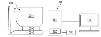
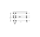
- FIG. 2 is a diagram illustrating a configuration of the image processing system 10 including the image processing apparatus 101 according to the present embodiment.
- an image processing apparatus 101 is connected to a tomographic imaging apparatus 100 (also referred to as OCT), an external storage unit 102, an input unit 103, and a display unit 104 via an interface. It is constituted by.
- the tomographic image capturing apparatus 100 is an apparatus that captures a tomographic image of the eye.
- SD-OCT is used as the tomographic imaging apparatus 100.
- SS-OCT may be used.
- a measurement optical system 100-1 is an optical system for acquiring an anterior ocular segment image, an SLO fundus image of a subject eye, and a tomographic image.
- the stage unit 100-2 enables the measurement optical system 100-1 to move back and forth and right and left.
- the base unit 100-3 incorporates a spectrometer described later.
- the image processing apparatus 101 is a computer that executes control of the stage unit 100-2, alignment operation control, tomographic image reconstruction, and the like.
- the external storage unit 102 stores a tomographic program, patient information, imaging data, fundus blood vessel images, past examination image data, measurement data such as avascular region information, and the like.
- the input unit 103 instructs the computer, and specifically includes a keyboard and a mouse.
- the display unit 104 includes a monitor, for example.
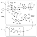
- the configuration of the measurement optical system and the spectroscope in the tomographic imaging apparatus 100 of the present embodiment will be described with reference to FIG. 2B.
- An objective lens 201 is installed facing the eye 200, and a first dichroic mirror 202 and a second dichroic mirror 203 are arranged on the optical axis.
- a first dichroic mirror 202 and a second dichroic mirror 203 are arranged on the optical axis.
- the optical path 251 for the SLO optical system and the fixation lamp includes SLO scanning means 204, lenses 205 and 206, a mirror 207, a third dichroic mirror 208, an APD (Avalanche Photodiode) 209, an SLO light source 210, and a fixation lamp 211.
- the mirror 207 is a prism on which a perforated mirror or a hollow mirror is deposited, and separates illumination light from the SLO light source 210 and return light from the eye to be examined.
- the third dichroic mirror 208 separates the optical path of the SLO light source 210 and the optical path of the fixation lamp 211 for each wavelength band.
- the SLO scanning means 204 scans the light emitted from the SLO light source 210 on the eye 200 to be examined, and includes an X scanner that scans in the X direction and a Y scanner that scans in the Y direction.
- the X scanner needs to perform high-speed scanning, it is a polygon mirror, and the Y scanner is a galvanometer mirror.
- the lens 205 is driven by a motor (not shown) for focusing the SLO optical system and the fixation lamp 211.
- the SLO light source 210 generates light having a wavelength near 780 nm.
- the APD 209 detects return light from the eye to be examined.
- the fixation lamp 211 generates visible light to promote fixation of the subject.
- the light emitted from the SLO light source 210 is reflected by the third dichroic mirror 208, passes through the mirror 207, passes through the lenses 206 and 205, and is scanned on the eye 200 by the SLO scanning unit 204.
- the return light from the eye 200 to be examined returns to the same path as the illumination light, and is then reflected by the mirror 207 and guided to the APD 209 to obtain an SLO fundus image.
- the light emitted from the fixation lamp 211 passes through the third dichroic mirror 208 and the mirror 207, passes through the lenses 206 and 205, and forms a predetermined shape on the eye 200 by the SLO scanning unit 204, Encourage the patient to fixate.
- the CCD 215 has sensitivity at a wavelength of irradiation light for anterior ocular segment observation (not shown), specifically, around 970 nm.
- the split prism 214 is disposed at a position conjugate with the pupil of the eye 200 to be examined, and the distance in the Z-axis direction (optical axis direction) of the measurement optical system 100-1 with respect to the eye 200 is used as a split image of the anterior eye portion. It can be detected.
- the optical path 250 of the OCT optical system constitutes the OCT optical system as described above, and is for taking a tomographic image of the eye 200 to be examined. More specifically, an interference signal for forming a tomographic image is obtained.
- the XY scanner 216 is for scanning light on the eye 200 to be examined, and is illustrated as a single mirror in FIG. 2B, but is actually a galvanometer mirror that performs scanning in the XY biaxial directions.
- the lens 217 is driven by a motor (not shown) in order to focus the light from the OCT light source 220 emitted from the fiber 224 connected to the optical coupler 219 on the eye 200 to be examined.
- the return light from the eye 200 is simultaneously incident on the tip of the fiber 224 in the form of a spot.
- 220 is an OCT light source
- 221 is a reference mirror
- 222 is a dispersion compensating glass
- 223 is a lens
- 219 is an optical coupler
- 224 to 227 are connected to the optical coupler and integrated into a single mode
- 230 is a spectroscope.
- These configurations constitute a Michelson interferometer.
- the light emitted from the OCT light source 220 is split into the measurement light on the optical fiber 224 side and the reference light on the optical fiber 226 side through the optical coupler 219 through the optical fiber 225.
- the measurement light is irradiated to the eye 200 to be observed through the above-mentioned OCT optical system optical path, and reaches the optical coupler 219 through the same optical path due to reflection and scattering by the eye 200 to be observed.
- the reference light reaches the reference mirror 221 and is reflected through the optical fiber 226, the lens 223, and the dispersion compensation glass 222 inserted to match the wavelength dispersion of the measurement light and the reference light. Then, it returns on the same optical path and reaches the optical coupler 219.
- the measurement light and the reference light are combined by the optical coupler 219 and become interference light.
- interference occurs when the optical path length of the measurement light and the optical path length of the reference light are substantially the same.
- the reference mirror 221 is held so as to be adjustable in the optical axis direction by a motor and a drive mechanism (not shown), and the optical path length of the reference light can be adjusted to the optical path length of the measurement light.
- the interference light is guided to the spectroscope 230 via the optical fiber 227.
- the polarization adjusting units 228 and 229 are provided in the optical fibers 224 and 226, respectively, and perform polarization adjustment. These polarization adjusting units have several portions where the optical fiber is looped.
- the spectroscope 230 includes lenses 232 and 234, a diffraction grating 233, and a line sensor 231.
- the interference light emitted from the optical fiber 227 becomes parallel light through the lens 234, and then is split by the diffraction grating 233 and imaged by the lens 232 on the line sensor 231.
- the OCT light source 220 is an SLD (Super Luminescent Diode) that is a typical low-coherent light source.
- the center wavelength is 855 nm and the wavelength bandwidth is about 100 nm.
- the bandwidth is an important parameter because it affects the resolution of the obtained tomographic image in the optical axis direction.
- SLD is selected here, but it is sufficient that low-coherent light can be emitted, and ASE (Amplified Spontaneous Emission) or the like can be used.
- Near-infrared light is suitable for the center wavelength in view of measuring the eye.
- the center wavelength affects the lateral resolution of the obtained tomographic image, it is desirable that the center wavelength be as short as possible. For both reasons, the center wavelength was 855 nm.
- a Michelson interferometer is used as an interferometer, but a Mach-Zehnder interferometer may be used. It is desirable to use a Mach-Zehnder interferometer when the light amount difference is large and a Michelson interferometer when the light amount difference is relatively small according to the light amount difference between the measurement light and the reference light.
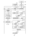
- the image processing apparatus 101 is a personal computer (PC) connected to the tomographic imaging apparatus 100, and includes an image acquisition unit 101-01, a storage unit 101-02, an imaging control unit 101-03, an image processing unit 101-04, A display control unit 101-05 is provided.
- the arithmetic processing unit CPU executes software modules that implement the image acquisition unit 101-01, the imaging control unit 101-03, the image processing unit 101-04, and the display control unit 101-05. Realize the function.
- the present invention is not limited to this.
- the image processing unit 101-04 may be realized by dedicated hardware such as an ASIC, or the display control unit 101-05 may be a dedicated processor such as GPU different from the CPU. It may be realized by using. Further, the connection between the tomographic imaging apparatus 100 and the image processing apparatus 101 may be configured via a network.
- the image acquisition unit 101-01 acquires signal data of the SLO fundus image and tomographic image captured by the tomographic image capturing apparatus 100.
- the image acquisition unit 101-01 includes a tomographic image generation unit 101-11 and a motion contrast data generation unit 101-12.
- the tomographic image generation unit 101-11 acquires signal data (interference signal) of a tomographic image captured by the tomographic imaging apparatus 100, generates a tomographic image by signal processing, and stores the generated tomographic image in the storage unit 101-02. To store.
- the imaging control unit 101-03 performs imaging control for the tomographic imaging apparatus 100.
- the imaging control includes instructing the tomographic imaging apparatus 100 regarding the setting of imaging parameters and instructing the start or end of imaging.
- the image processing unit 101-04 includes an alignment unit 101-41, a synthesis unit 101-42, a correction unit 101-43, an image feature acquisition unit 101-44, a projection unit 101-45, and an analysis unit 101-46.
- the image acquisition unit 101-01 and the synthesis unit 101-42 described above are an example of an acquisition unit according to the present invention.
- the synthesizing unit 101-42 synthesizes a plurality of motion contrast data generated by the motion contrast data generating unit 101-12 based on the alignment parameter obtained by the alignment unit 101-41, and generates a synthesized motion contrast image. .
- the correction unit 101-43 performs a process of suppressing projection artifacts generated in the motion contrast image two-dimensionally or three-dimensionally (projection artifacts will be described in S314).
- the image feature acquisition unit 101-44 acquires the layer boundary of the retina and choroid, the position of the fovea and the center of the optic disc from the tomographic image.
- the projection unit 101-45 projects a motion contrast image in a depth range based on the layer boundary position acquired by the image feature acquisition unit 101-44, and generates a motion contrast front image. That is, the projection unit 101-45 generates a motion contrast front image using data of at least a part of the depth range in the three-dimensional motion contrast image.
- the analysis unit 101-46 includes an enhancement unit 101-461, an extraction unit 101-462, a measurement unit 101-463, and a coordinate conversion unit 101-464, and performs an avascular region specification and measurement process from the motion contrast front image. .
- the emphasizing units 101 to 461 execute blood vessel emphasizing processing.
- the extraction unit 101-462 performs boundary extraction of an NPA that is an example of an avascular region based on the blood vessel emphasized image.
- the measurement units 101 to 463 as an example of a generation unit generate an extracted NPA mask image.
- the measurement units 101 to 463 calculate measurement values such as the area and volume of the NPA.
- the coordinate conversion unit 101-464 performs coordinate conversion of the motion contrast front image.
- An example of coordinate conversion is conversion from orthogonal coordinates to polar coordinates, or from polar coordinates to orthogonal coordinates.
- the external storage unit 102 includes information on the eye to be examined (patient name, age, sex, etc.), captured images (tomographic images and SLO images / OCTA images), composite images, imaging parameters, avascular region information, measurement values, The parameters set by the operator are stored in association with each other.
- the input unit 103 is, for example, a mouse, a keyboard, a touch operation screen, and the like, and the operator gives an instruction to the image processing apparatus 101 and the tomographic imaging apparatus 100 via the input unit 103.
- the configuration of the image processing apparatus 101 according to the present invention does not necessarily include all the configurations described above.
- the alignment unit 101-41, the synthesis unit 101-42, the correction unit 101-43, and the like are omitted. Also good.
- FIG. 3 is a flowchart showing a flow of operation processing of the entire system in the present embodiment.
- the image enhancement processing in step S320 is not an essential step and may be omitted.
- the image processing unit 101-04 acquires a motion contrast image that is a fundus blood vessel image.
- the image processing unit 101-04 may acquire a fundus blood vessel image already stored in the external storage unit 102.
- the image processing unit 101-04 controls the measurement optical system 100-1 to acquire the acquired tomographic image.
- An example of generating and acquiring a motion contrast image is shown. Details of these processes will be described later. Or in this embodiment, it is not limited to this acquisition method, Other methods may be sufficient if a fundus blood vessel image is acquired.
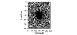
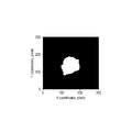
- a motion contrast image as shown in FIG. 5A will be described as an example of the fundus blood vessel image in the present embodiment.
- the present invention is not limited to this, and other fundus blood vessel images such as a fluorescein angiography image, indocyanine green: ICG) An ocular angiographic image, an OCT angiographic image or the like may be used.
- step S320 the enhancement unit 101-461 performs image enhancement of the fundus blood vessel image while minimizing the influence of noise.
- a specific description of this process is as follows. 1) Apply a Gaussian Low Pass Filter (LPF) of a narrow window size to the fundus blood vessel image acquired in step S310 to generate a Light-Filtered OCTA image (LF-OCTA image).
- the narrow window size is 3 pixels.
- LPF Gaussian Low Pass Filter
- SF-OCTA image Strong-Filtered OCTA image
- the width window size is 85 pixels.
- RV-OCTA Relativity Variation OCTA
- Binarization of RV-OCTA is performed using a specific threshold RL (ratio limit).
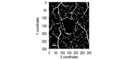
- the enhancement unit 101-461 performs enhancement processing for enhancing the blood vessel structure in the fundus blood vessel image by performing binarization processing on the fundus blood vessel image.
- the threshold value RL is 1. If each RV-OCTA pixel value is less than or equal to RL, the pixel is set to zero. Otherwise, the pixel is set to 1.
- FIG. 5B shows an example of the processing result of this step.
- the image processing unit 101-04 which is an example of a pole determining unit, determines the pole of the avascular region in the fundus blood vessel image.
- a method for determining the pole a method by a user operation (not shown) acquired by the input unit 103 is used. Specifically, when the image processing apparatus 101 displays an OCTA image on the display unit 104 and the user selects one point of the NPA in the OCTA image using a mouse, a keyboard, a touch screen, or other input device, the operation is performed by the input unit. 103 obtains and sends the selected information to the image processing apparatus 101.
- the present embodiment is not limited to this method, and a method of automatically determining the pole based on the fundus blood vessel image or the analysis result of the fundus image may be used.
- a method of automatically determining the pole based on the fundus blood vessel image or the analysis result of the fundus image may be used.
- -A strong low pass filter is applied to the OCTA image, and a region of minimum intensity is detected based on the analysis result.
- -Detection is performed using analysis results of other modality fundus images (eg, SLO and fundus camera images). For example, one point in the detected area may be determined as a pole.
- step S340 the image processing unit 101-04, which is an example of the area specifying unit, specifies the NPA area including the pole using the pole determined in step S330. At this time, the determined pole is the origin of polar coordinates. The NPA region is specified by determining the boundary line of the NPA region based on the determined pole.
- step S330 the image processing unit 101-04, which is an example of a position determining unit, determines the position of the avascular region in the fundus blood vessel image in accordance with an instruction from the examiner with respect to the fundus blood vessel image of the eye to be examined. Also good.
- the image processing unit 101-04 which is an example of a boundary line determination unit, may determine the boundary line of the avascular region based on the determined position.
- the determined position corresponds to a position for determining the boundary line. Details of these processes will be described later.
- step S350 the image processing unit 101-04 sends the NPA information specified in step S340 to the storage unit 101-02, and the storage unit 101-02 stores the NPA information.
- step S350 the storage unit 101-02 sends the stored NPA information and the fundus blood vessel image to the display unit 104, and displays the NPA information superimposed on the fundus blood vessel image. That is, the display control unit 101-05 causes the display unit 104 to display information indicating the specified NPA region in a state of being superimposed on the fundus blood vessel image. In addition, the display control unit 101-05 causes the display unit 104 to display information indicating the determined boundary line of the NPA region while being superimposed on the fundus blood vessel image.
- the information is preferably, for example, a line indicating the outer frame of the region or a color indicating the inside of the region, but may be any display as long as the region can be identified.
- the display control unit 101-05 may display the measurement value related to the NPA region on the display unit 104 in a state of being superimposed on the fundus blood vessel image. Further, it is preferable that the position of the information indicating the boundary line of the determined NPA area can be changed in accordance with an instruction from the examiner. As a result, convenience for the examiner is improved, and diagnostic efficiency is also improved.
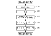
- step S314 a specific processing procedure for obtaining a motion contrast image that is a fundus blood vessel image in step S310 of the present embodiment will be described with reference to FIG. 3B.
- the composite motion contrast image generation process in step S314 is not an essential process and may be omitted.
- step S ⁇ b> 311 the image control unit 101-03 sets an OCTA image capturing condition instructed to the tomographic image capturing apparatus 100 by operating the input unit 103. Specifically, 1) selection or registration of an inspection set 2) selection or addition of a scan mode in the selected inspection set 3) a procedure for setting imaging parameters corresponding to the scan mode. In this embodiment, the following settings are made.
- step S302 OCTA imaging (under the same imaging conditions) is repeatedly executed a predetermined number of times with appropriate breaks.
- Step S312 when the input unit 103 receives an instruction to start imaging from the operator, the input unit 103 starts repeated OCTA imaging under the imaging conditions specified in step S311.
- the imaging control unit 101-03 instructs the tomographic imaging apparatus 100 to repeatedly perform OCTA imaging based on the setting instructed by the operator in step S311, and the tomographic imaging apparatus 100 corresponds to the OCT tomographic image.
- the number of repeated imaging in this step is three. However, the number of repeated imaging may be set to an arbitrary number.
- the present invention is not limited to the case where the photographing time interval between repeated photographing is longer than the photographing time interval of tomographic images in each repeated photographing, and the present invention also includes a case where both are substantially the same.
- the tomographic imaging apparatus 100 also acquires an SLO image and executes a tracking process based on the SLO moving image.
- the reference SLO image used for tracking processing in repeated OCTA imaging is the reference SLO image set in the first repeated OCTA imaging, and a common reference SLO image is used in all repeated OCTA imaging.
- the same set values are used (not changed) for the selection of the left and right eyes and whether or not to perform the tracking process in addition to the imaging conditions set in step S311.
- step S313 the image acquisition unit 101-01 and the image processing unit 101-04 generate a motion contrast image based on the OCT tomographic image acquired in S302.
- the tomographic image generation unit 101-11 performs wave number conversion, fast Fourier transform (FFT), and absolute value conversion (amplitude acquisition) on the interference signal acquired by the image acquisition unit 101-01, thereby obtaining a tomographic image for one cluster. Generate an image.
- FFT fast Fourier transform
- absolute value conversion amplitude acquisition
- the alignment unit 101-41 aligns the tomographic images belonging to the same cluster and performs an overlay process.
- the image feature acquisition unit 101-44 acquires layer boundary data from the superimposed tomographic image.
- a variable shape model is used as a layer boundary acquisition method, but any known layer boundary acquisition method may be used.
- the layer boundary acquisition process is not essential. For example, when the motion contrast image is generated only in three dimensions and the two-dimensional motion contrast image projected in the depth direction is not generated, the layer boundary acquisition process can be omitted.
- the motion contrast data generation unit 101-12 calculates the motion contrast between adjacent tomographic images in the same cluster. In this embodiment, a decorrelation value Mxy is obtained as motion contrast based on the following equation (1).
- Axy represents the amplitude (of the complex data after FFT processing) at the position (x, y) of the tomographic image data A
- Bxy represents the amplitude at the same position (x, y) of the tomographic data B. 0 ⁇ Mxy ⁇ 1, and the closer the amplitude value is, the closer the value is to 1.
- the decorrelation calculation process as in equation (1) is performed between any adjacent tomographic images (belonging to the same cluster), and the average of the obtained motion contrast values (number of tomographic images per cluster minus 1) is calculated. An image having pixel values is generated as a final motion contrast image.
- the motion contrast is calculated based on the amplitude of the complex data after the FFT processing, but the method of calculating the motion contrast is not limited to the above.
- motion contrast may be calculated based on phase information of complex number data, or motion contrast may be calculated based on both amplitude and phase information.
- the motion contrast may be calculated based on the real part and the imaginary part of the complex data.
- the decorrelation value is calculated as the motion contrast, but the method of calculating the motion contrast is not limited to this.
- the motion contrast may be calculated based on the difference between the two values, or the motion contrast may be calculated based on the ratio between the two values.
- the final motion contrast image is obtained by obtaining an average value of a plurality of acquired decorrelation values, but the present invention is not limited to this.
- an image having a median value or a maximum value of a plurality of acquired decorrelation values as pixel values may be generated as a final motion contrast image.
- step S314 the image processing unit 101-04 generates a high-contrast composite motion contrast image by three-dimensionally aligning and averaging the motion contrast image groups obtained through repeated OCTA imaging.
- the composition process is not limited to simple addition averaging. For example, it may be an average value after arbitrarily weighting the luminance value of each motion contrast image, or an arbitrary statistical value including a median value may be calculated. Further, the case where the alignment process is performed two-dimensionally is also included in the present invention.
- the composition unit 101-42 may determine whether or not a motion contrast image inappropriate for the composition process is included, and then perform the composition process by removing the motion contrast image determined to be inappropriate. For example, when an evaluation value (for example, an average value of decorrelation values or fSNR) is out of a predetermined range with respect to each motion contrast image, it may be determined to be unsuitable for the synthesis process.
- an evaluation value for example, an average value of decorrelation values or fSNR
- the correction unit 101-43 performs a process of three-dimensionally suppressing (reducing) the projection artifacts generated in the motion contrast image.
- the projection artifact refers to a phenomenon in which the motion contrast in the retinal surface blood vessels is reflected on the deep layer side (the deep retinal layer, the outer retinal layer, or the choroid), and a high decorrelation value is actually generated in the deep layer region where no blood vessel exists.
- the correcting unit 101-43 executes a process for suppressing the projection artifact 802 generated on the three-dimensional synthesized motion contrast image.
- Step-downExponential Filtering the projection artifact is suppressed by executing the processing represented by Expression (2) for each A scan data on the three-dimensional motion contrast image.
- ⁇ is a negative attenuation coefficient
- D (x, y, z) is a decorrelation value before the projection artifact suppression process
- D E (x, y, z) is a decorrelation value after the suppression process. Represents.
- the projection unit 101-45 projects a motion contrast image in a depth range based on the layer boundary position acquired by the image feature acquisition unit 101-44 in S303, and generates a motion contrast front image.
- projection may be performed in an arbitrary depth range, in this embodiment, two types of front synthesized motion contrast images are generated in the depth range of the retina surface layer and the deep retina layer.
- MIP maximum value projection
- AIP average value projection
- AIP average intensity projection
- step S315 the image processing apparatus 101 obtains the acquired image group (SLO image or tomographic image), imaging condition data of the image group, and generated generation condition data associated with the generated three-dimensional and motion contrast front image,
- the data is stored in the external storage unit 102 in association with the information for identifying the test eye.
- step S340 of the present embodiment a specific processing procedure for specifying the NPA region of the fundus blood vessel image (OCTA image) in step S340 of the present embodiment will be described with reference to FIG. 3C.
- the smoothing process in step S343 is not an essential process and may be omitted.
- step S341 the coordinate conversion unit 101-462 converts the orthogonal coordinate OCTA image to the polar coordinate OCTA image based on the determined pole. That is, the coordinate conversion unit 101-462 executes coordinate conversion processing for converting a fundus blood vessel image from an orthogonal coordinate image to a polar coordinate image (an example of a coordinate image different from the orthogonal coordinate image) based on the determined pole.
- the value of the angle step ⁇ depends on the OCTA image size S and the pixel dimension p.
- the angle step for generating the loss-less image in polar coordinates can be calculated from the cosine method as shown in Equation (3).
- acos is an arccosine function
- size S is the distance in mm from the center of the OCTA image to its furthest point. For example, if the resolution of a 3x3mm OCTA image is 232x232 pixels,
- the angle step ⁇ is about 0.35 degrees.
- i is the index of the sample.
- the first sample angle, ⁇ (0) 0 degrees.
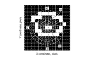
- FIG. 5C shows the processing result of this step.
- the coordinate conversion is described by taking, as an example, the conversion from orthogonal coordinates to polar coordinates.
- the present invention is not limited to this conversion method, and other methods, for example, conversion to non-orthogonal coordinates (for example, spherical or cylindrical coordinates) may be used.
- step S342 the extraction unit 101-462, which is an example of a boundary line determination unit, extracts an NPA boundary line from the polar coordinate image generated in step S341.
- the edge first found from the pole (the lowermost end of the pole image) is set as the NPA boundary line candidate.
- the first edge is represented by a dotted line in FIG.
- step S343 the extraction unit 101-462, which is an example of a smoothing processing unit, performs the smoothing process on the NPA boundary line candidate extracted in step S342.
- a moving media filter moving median filter
- the purpose of the smoothing process is to delete the spike (spike, singular point) of the boundary line candidate extracted in step S343. These spikes are generated from discontinuities in the vasculature and are considered unsuitable as NPA boundaries.
- the solid line in FIG. 6 shows the NPA boundary line after the smoothing process.
- the present invention is not limited to this method, and for example, a moving average method, a Savitzky-Golay filter, a filter based on a Fourier transform method, or the like may be used.
- step S344 the coordinate conversion unit 101-464 converts the polar NPA boundary line image extracted in step S343 into orthogonal coordinates.
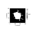
- step S345 the measurement units 101 to 463, which are examples of the generation unit, generate an NPA area mask image.
- the measurement unit 101-463 uses the NPA boundary line of the orthogonal coordinates generated in step S344 to change the pixels in the NPA boundary line to white pixels and the other pixels to black pixels, so that the NPA mask image Generate.
- a white area of the NPA mask image is an NPA area.
- FIG. 7 shows an example of an NPA mask image.
- FIG. 8A shows an example where there is noise in the OCTA image.
- step S342 checks if the pixel is a non-signal pixel (pixel value equals zero) and does the following:
- Radius 0 is the signal If it is a pixel (there is a signal in the pixel), the Radius value is incremented sequentially until a non-signal pixel is found. After a non-signal pixel is found, the Radius value is incremented sequentially until more signal pixels are found, and when the first signal pixel is found, it is made the NPA boundary.
- other processing methods may be used. For example, when determining a pole, when there is a signal in the pixel, a method may be used in which a peripheral non-signal pixel is searched and the non-signal pixel is used as a pole.
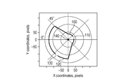
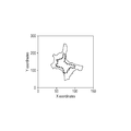
- FIG. 9A shows the NPA region of the OCTA image in the Cartesian coordinate system.
- the solid line 100 and the solid line 120 are NPA boundary lines.
- FIG. 9B shows a polar coordinate image of the same image.
- the gaps 110 and 130 are the same size, but due to the distance from the pole 140, the sizes of the gaps 110 and 130 in the polar coordinate image are greatly different, that is, the gap 110 is larger than the gap 130.
- the window size of the moving media filter is set as shown in Expression (4).
- R is the distance from the pole.
- ⁇ 0.05 mm is described as an example, but the value is not limited to this value.
- the window size may be determined by, for example, a Savitzky-Golay filter or other expressions.
- the OCTA image is used as the fundus blood vessel image.
- the present invention is not limited to this, and other fundus blood vessel images such as a fluorescein angiographic image, an ICGA angiographic image, or other A contrast fundus image may be used.
- the orthogonal coordinate OCTA image is converted to the polar coordinate OCTA image, the extraction of the NPA boundary line is accelerated, and the boundary line is smoothed.
- spikes in the boundary line are reduced, and it is possible to improve the accuracy of specifying the NPA region.
- the polar coordinate OCTA image is generated, the NPA boundary line is extracted, and the NPA region specifying method is described.
- the NPA area specification is calculated based on one pole, it is easily affected by image noise.
- the pole determining means determines one pole of the avascular region and determines at least one pole based on the boundary line of the avascular region corresponding to one pole.
- the boundary line determination means determines one boundary line of the avascular region based on a plurality of boundary lines corresponding to a plurality of poles including one pole and at least one pole.
- Step S810, Step S820, Step S830, and Step S920 are the same as Step S310, Step S320, and Step S330 of the processing flow of the first embodiment, respectively, and thus description thereof is omitted.
- step S840 and step S870 are the same as step S340 of the processing flow of the first embodiment, description thereof will be omitted.
- step S850 the image processing unit 101-04, which is an example of a pole determining unit, acquires a pole candidate to be added from the NPA area specified in the previous step. That is, the pole determining means first determines one pole (first pole) in step S830, and determines at least one pole (at least one other of the plurality of poles) different from one pole. .
- the reduction ratio 0.6; the reduction center: the center of gravity of the region.
- a plurality of points are selected from the outline of the reduced area.
- 30 points placed at substantially equal intervals on the contour line are set as a plurality of pole (center point) candidates.
- the determination of the reduction ratio and the center is not limited by this method.
- the reduction ratio 0.9;
- the present invention is not limited to this example.
- the number of points may be determined according to the size of the contour line.
- the method for determining a plurality of pole candidates is not limited to the above method, and for example, pole candidates may be placed two-dimensionally at equal intervals in the NPA region. Alternatively, other methods may be used.
- step S860 the image processing unit 101-04 selects one candidate from the plurality of pole candidates calculated in step S850.
- the pole candidate is referred to as a pole (J) or a Jth candidate.
- step S870 the image processing unit 101-04 specifies the NPA (J) region using the pole (J) selected in step S860. Since this process is the same as step S340 in the first embodiment, a description thereof is omitted here.
- the NPA region identified using the pole (J) is referred to as NPA (J) or intermediate NPA region.
- step S880 the image processing unit 101-04 stores the intermediate NPA (J) area specified by using the pole (J) in step S870 in the storage unit 101-02.
- step S890 the image processing unit 101-04 determines whether there is a next candidate for the plurality of poles acquired in step S850. If there is a next candidate, it is set as the pole (J + 1), and the process proceeds to step S860. If the identification of each intermediate NPA has been completed from all the poles acquired in step S850, the process proceeds to step S900.
- step S900 the image processing unit 101-04, which is an example of a boundary line determination unit, synthesizes the final NPA region using all the intermediate NPA regions saved in step S880. That is, the boundary line determination unit according to the present embodiment determines one boundary line by combining a plurality of regions defined by a plurality of boundary lines corresponding to a plurality of poles.
- the boundary line determination unit determines one boundary line by combining a plurality of regions defined by a plurality of boundary lines corresponding to a plurality of poles.
- the intermediate NPA areas are added together, and the number of NPA areas common to each pixel (position in the NPA area) is used as a weight.
- FIG. 13 shows an example. A pixel (position) having a certain weight or more (eg, half the number of pole candidates) is set as the final NPA area.
- Other synthesis methods may be used. For example, all intermediate NPA areas may be ANDed.
- step S910 the image processing unit 101-04 determines whether the accuracy of the final NPA synthesized in step S900 is sufficient.
- addition candidates are again performed from the synthesized final NPA. That is, the processing loop from step S850 to step S900 is executed again.
- the processing loop from step S850 to step S900 is executed twice.
- fixed number of times (2 times) was demonstrated here as an example, the other fixed number of times may be sufficient.
- a new NPA may be further synthesized using NPA synthesis results obtained from all the processing loops.
- step S910 if the process loop is turned once again, the process returns to S850. If the NPA synthesis is sufficient, the process proceeds to step S920. Specifically, a value indicating a change between a boundary line of an avascular region corresponding to one pole and one boundary line determined based on a plurality of boundary lines corresponding to a plurality of poles is equal to or greater than a threshold value. Is determined to be insufficient. That is, the pole determining unit according to the present embodiment determines again as a pole to which at least one pole is added when the value indicating the change is equal to or greater than the threshold value. If the value indicating the change is less than the threshold value, it is determined to be sufficient. That is, the pole determining unit according to the present embodiment ends the determination of at least one pole when the value indicating the change is less than the threshold value. Note that the value indicating the change is, for example, the area of the region defined by the boundary line.
- step S920 the image processing unit 101-04 stores the NPA area information calculated in the above processing in the storage unit 101-02.
- the value of the angle step ⁇ in step S341 depends on the size S of the OCTA image and the pixel dimension p, and a fixed value is used as the angle step ⁇ .
- the value is not limited to a fixed value and can be changed. It may be.
- the angle step ⁇ (i) may be determined so that the sampling points are substantially equally spaced on the NPA boundary line.
- the sampling angle ⁇ (i) ⁇ (i ⁇ 1) + ⁇ (i) is set.
- the following process is an example.
- step S342 the image processing unit 101-04 extracts the NPA boundary line, and then sets the angular step ⁇ (i so that the sampling points (i) are equally spaced (or substantially equally spaced) on the boundary line. ).
- the angle step ⁇ (i) is used for the coordinate conversion in step S341.
- FIG. 10 shows an example.
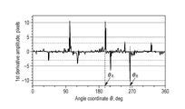
- a pole candidate to be added may be acquired based on the analysis result of the first derivative of the boundary line on the polar coordinates of the NPA region identified in the previous step in step S850.
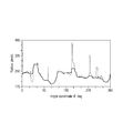
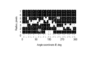
- FIG. 14A shows the borderline of the NPA region in polar coordinates.
- FIG. 14B shows the result of the primary differentiation corresponding to the boundary line.
- a pole candidate is decided based on the peak which appeared in the primary differentiation.
- the threshold value 3 pixels.
- the dotted line in FIG. 14B indicates the threshold value.
- a fixed threshold value is used for explanation, but the value is not limited to this value.
- the value may depend on the angle step ⁇ or may be another value.
- the value of the first derivative determines the pole candidate based on the position exceeding the ⁇ threshold.
- FIG. 15 is a partial enlargement of FIG. 14A including ⁇ A and ⁇ B.
- the distance RA is the distance R at the position of the angle ( ⁇ A + ⁇ ).
- the pole candidate A to be added is ( ⁇ A + ⁇ , ⁇ RA).
- the pole candidate B is ( ⁇ B ⁇ , ⁇ xRB). Whether ⁇ is added to or subtracted from the angle ⁇ is determined based on whether the first derivative is true or negative.
- the closer to ⁇ 1.0, the more pole candidates can be placed closer to the singular point of a complex region.
- ⁇ Modification 3 of the second embodiment> the fixed number of times has been described as an example in step S910.
- the present invention is not limited to this method. For example, it may be determined whether to execute the processing loop again based on the change in the NPA synthesis result in step S900. That is, if the difference between the NPA synthesis result and the result of the preprocessing loop is small, the processing loop may be stopped. Next, an example will be described.
- the threshold value of the end condition is set to 5%.
- the condition change ⁇ A may be determined based on the processing time and the complexity of the NPA area. If the NPA region area value A (k) tends to converge, the processing loop may be terminated. For example, if the change ⁇ A (k) in the processing loop k (ie, ⁇ A (k) ⁇ A (k ⁇ 1)) is equal to or less than the threshold value, the processing may be terminated.
- the NPA area is specified based on each pole, and further, the synthesis in the specified plurality of NPA areas is performed.
- step S865 is added between step S860 and step S870. The operation of step S865 is as follows.
- Step S865 the enhancement unit 101-461 performs image enhancement of the fundus blood vessel image while minimizing the influence of noise.
- Step S865 is the same as step S320, but the binarization process (detailed process 4 of step S320) is different, and will be described in detail here.
- step S320 of the present embodiment the enhancement unit 101-461 performs three-dimensional image enhancement of the fundus blood vessel image while minimizing the influence of noise.
- the LPF process used in step S320 of the present embodiment uses a three-dimensional filter. Other processes are also performed three-dimensionally.
- step S341 of the present embodiment the coordinate conversion unit 101-462 converts, based on the determined poles, a three-dimensional OCTA image with orthogonal coordinates into a three-dimensional OCTA image with spherical coordinates (three-dimensional polar coordinates).
- the determined pole is the origin of the three-dimensional polar coordinates.
- step S344 of the present embodiment the coordinate conversion unit 101-462 converts the spherical coordinate three-dimensional OCTA image into a rectangular coordinate three-dimensional OCTA image based on the determined pole.
- step S850 of the present embodiment the image processing unit 101-04 acquires a pole candidate to be added from the three-dimensional NPA region specified in the previous step.
- the volume boundary surface of the reduced three-dimensional NPA region is used.
- a process performs a two-dimensional process and a similar process.
- the method is not limited to this method, and other three-dimensional processing methods may be used.
- ⁇ Modification 1 of the fourth embodiment> the description has been made using spherical coordinates for three-dimensional coordinate conversion, but other three-dimensional coordinates may be used.
- coordinate conversion from three-dimensional orthogonal coordinates to cylindrical coordinates may be used.
- processing such as LPF may be performed two-dimensionally.
- the retina is more like a cylinder than a sphere, so it can be processed more appropriately with this method.
- OCTA image three-dimensional fundus blood vessel image
Landscapes
- Life Sciences & Earth Sciences (AREA)
- Health & Medical Sciences (AREA)
- Medical Informatics (AREA)
- Biophysics (AREA)
- Ophthalmology & Optometry (AREA)
- Engineering & Computer Science (AREA)
- Biomedical Technology (AREA)
- Heart & Thoracic Surgery (AREA)
- Physics & Mathematics (AREA)
- Molecular Biology (AREA)
- Surgery (AREA)
- Animal Behavior & Ethology (AREA)
- General Health & Medical Sciences (AREA)
- Public Health (AREA)
- Veterinary Medicine (AREA)
- Eye Examination Apparatus (AREA)
Abstract
画像処理装置は、被検眼の眼底血管画像における無血管領域の極を決定する極決定手段と、決定された極に基づいて、眼底血管画像を直交座標画像とは異なる座標画像に変換する座標変換処理を実行する座標変換手段と、異なる座標画像における無血管領域の境界線を決定する境界線決定手段と、を備える。
Description
開示の技術は、画像処理装置、画像処理方法及びプログラムに関する。
光干渉断層計(OCT;Optical Coherence Tomography)などの眼部の断層画像撮影装置を用いると、網膜層内部の状態を3次元的に観察できる。この断層画像撮影装置は、疾病の診断をより的確に行うのに有用であることから眼科診療に広く用いられている。OCTの形態として、例えば広帯域な光源とマイケルソン干渉計を組み合わせたTD-OCT(Time domain OCT)がある。これは、参照ミラーの位置を一定速度で移動させて信号アームで取得した後方散乱光との干渉光を計測し、深さ方向の反射光強度分布を得るように構成されている。しかし、このようなTD-OCTでは機械的な走査が必要となるため高速な画像取得は難しい。そこで、より高速な画像取得法として広帯域光源を用い、分光器で干渉信号を取得するSD-OCT(Spectral domain OCT)や高速波長掃引光源を用いることで時間的に分光するSS-OCT(Swept Source OCT)が開発され、より広画角な断層画像を取得できるようになっている。
一方、眼科診療では眼底血管の病態を把握するために眼底血管画像が用いられている。
そして、その眼底血管画像の撮影のためにこれまで侵襲的な蛍光眼底造影検査が行われてきた。近年は、眼底血管画像の作成にOCTを用いて非侵襲に眼底血管を3次元で描出するOCT Angiography(以下、OCTAと表記)技術が用いられるようになってきている。OCTAでは測定光で同一位置を複数回走査し、赤血球の変位と測定光との相互作用により得られるモーションコントラストを画像化する。図4は主走査方向が水平(x軸)方向で、副走査方向(y軸方向)の各位置(yi;1≦i≦n)においてr回連続でBスキャンを行うOCTA撮影の例を示している。なおOCTA撮像において同一位置で複数回走査することをクラスタ走査、同一位置で得られた複数枚の断層画像のことをクラスタと呼ぶ。クラスタ単位でモーションコントラストデータを生成し、1クラスタあたりの断層画像数(略同一位置での走査回数)を増やすと、OCTA画像のコントラストが向上することが知られている。
ここで、OCTA画像を用いて糖尿病網膜症の疾病診断を行うために、2次元のOCTA画像における中心窩無血管性域のような無血管領域の特定や、その無血管領域の面積の計測を行うことが、特許文献1に開示されている。このとき、2次元のOCTA画像のヒストグラム解析を行うことにより、2次元のOCTA画像における無血管領域の特定が行われる。
開示の画像処理装置の一つは、
被検眼の眼底血管画像における無血管領域の極を決定する極決定手段と、
前記決定された極に基づいて、前記眼底血管画像を直交座標画像とは異なる座標画像に変換する座標変換処理を実行する座標変換手段と、
前記異なる座標画像における前記無血管領域の境界線を決定する境界線決定手段と、を備える。
被検眼の眼底血管画像における無血管領域の極を決定する極決定手段と、
前記決定された極に基づいて、前記眼底血管画像を直交座標画像とは異なる座標画像に変換する座標変換処理を実行する座標変換手段と、
前記異なる座標画像における前記無血管領域の境界線を決定する境界線決定手段と、を備える。
従来のように、ヒストグラム解析を用いると、無血管領域の特定は画像のノイズに敏感になる。また、眼底血管画像全体を2次元的に処理する必要があり、処理が複雑で時間がかかる傾向がある。そこで、本実施形態の目的の一つは、眼底血管画像のノイズに対するロバスト性を向上しつつ、より高速に無血管領域の特定を行うことである。
なお、上記目的に限らず、後述する発明を実施するための形態に示す各構成により導かれる作用効果であって、従来の技術によっては得られない作用効果を奏することも本件の他の目的の1つとして位置付けることができる。
[第一実施形態]
以下、図面を参照しながら、第一実施形態について説明する。なお、本実施形態に係る画像処理装置は、入力された眼底血管画像に関して中心窩無血管性域(Foveal Avascular Zone:FAZ)や、無灌流領域(Non Perfusion Area:NPA)等の注目領域にある無血管領域の特定を行う。例えば、本実施形態に係る画像処理装置は、無血管領域の一例であるNPAの中に極を設定(決定)し、直交座標の眼底血管画像から極座標の眼底血管画像に変換する座標変換処理を実行する座標変換手段を備える。すなわち、本実施形態に係る座標変換手段は、決定された極に基づいて、眼底血管画像を直交座標画像とは異なる座標画像に変換する座標変換処理を実行する。ここで、直交座標画像とは異なる座標画像とは、例えば、極座標画像、球面座標画像(3次元の極座標画像)、円柱座標画像である。また、決定された極は、極座標の原点となる。そして、本実施形態に係る画像処理装置は、異なる座標画像における無血管領域の境界線を決定する境界線決定手段を備える。本実施形態は、極座標で表現されている眼底血管画像でNPA内の極を起点として最初のエッジ(端)を見つけることによって、NPAの境界線や領域を特定する方法例を示している。以下、図面を参照しながら、第一実施形態に係る画像処理装置を備える画像処理システムについて説明する。
以下、図面を参照しながら、第一実施形態について説明する。なお、本実施形態に係る画像処理装置は、入力された眼底血管画像に関して中心窩無血管性域(Foveal Avascular Zone:FAZ)や、無灌流領域(Non Perfusion Area:NPA)等の注目領域にある無血管領域の特定を行う。例えば、本実施形態に係る画像処理装置は、無血管領域の一例であるNPAの中に極を設定(決定)し、直交座標の眼底血管画像から極座標の眼底血管画像に変換する座標変換処理を実行する座標変換手段を備える。すなわち、本実施形態に係る座標変換手段は、決定された極に基づいて、眼底血管画像を直交座標画像とは異なる座標画像に変換する座標変換処理を実行する。ここで、直交座標画像とは異なる座標画像とは、例えば、極座標画像、球面座標画像(3次元の極座標画像)、円柱座標画像である。また、決定された極は、極座標の原点となる。そして、本実施形態に係る画像処理装置は、異なる座標画像における無血管領域の境界線を決定する境界線決定手段を備える。本実施形態は、極座標で表現されている眼底血管画像でNPA内の極を起点として最初のエッジ(端)を見つけることによって、NPAの境界線や領域を特定する方法例を示している。以下、図面を参照しながら、第一実施形態に係る画像処理装置を備える画像処理システムについて説明する。
図2は、本実施形態に係る画像処理装置101を備える画像処理システム10の構成を示す図である。図2に示すように、画像処理システム10は、画像処理装置101が、インタフェースを介して断層画像撮影装置100(OCTとも言う)、外部記憶部102、入力部103、表示部104と接続されることにより構成されている。断層画像撮影装置100は、眼部の断層画像を撮影する装置である。本実施形態においては、断層画像撮影装置100としてSD-OCTを用いるものとする。これに限らず、例えば、SS-OCTを用いて構成しても良い。図2Aにおいて、測定光学系100-1は前眼部像、被検眼のSLO眼底像、断層画像を取得するための光学系である。ステージ部100-2は、測定光学系100-1を前後左右に移動可能にする。ベース部100-3は、後述の分光器を内蔵している。画像処理装置101は、ステージ部100-2の制御、アラインメント動作の制御、断層画像の再構成などを実行するコンピュータである。外部記憶部102は、断層撮像用のプログラム、患者情報、撮影データ、眼底血管画像、過去検査の画像データ、や無血管領域情報等の計測データなどを記憶する。入力部103はコンピュータへの指示を行い、具体的にはキーボードとマウスから構成される。表示部104は、例えばモニタからなる。
(断層画像撮影装置の構成)
本実施形態の断層画像撮影装置100における測定光学系及び分光器の構成について図2Bを用いて説明する。まず、測定光学系100-1の内部について説明する。被検眼200に対向して対物レンズ201が設置され、その光軸上に第1ダイクロイックミラー202及び第2ダイクロイックミラー203が配置されている。これらのダイクロイックミラーによってOCT光学系の光路250、SLO光学系と固視灯用の光路251、及び前眼観察用の光路252とに波長帯域ごとに分岐される。
本実施形態の断層画像撮影装置100における測定光学系及び分光器の構成について図2Bを用いて説明する。まず、測定光学系100-1の内部について説明する。被検眼200に対向して対物レンズ201が設置され、その光軸上に第1ダイクロイックミラー202及び第2ダイクロイックミラー203が配置されている。これらのダイクロイックミラーによってOCT光学系の光路250、SLO光学系と固視灯用の光路251、及び前眼観察用の光路252とに波長帯域ごとに分岐される。
SLO光学系と固視灯用の光路251は、SLO走査手段204、レンズ205及び206、ミラー207、第3ダイクロイックミラー208、APD(Avalanche Photodiode)209、SLO光源210、固視灯211を有している。ミラー207は、穴あきミラーや中空のミラーが蒸着されたプリズムであり、SLO光源210による照明光と、被検眼からの戻り光とを分離する。第3ダイクロイックミラー208はSLO光源210の光路と固視灯211の光路とに波長帯域ごとに分離する。SLO走査手段204は、SLO光源210から発せられた光を被検眼200上で走査するものであり、X方向に走査するXスキャナ、Y方向に走査するYスキャナから構成されている。本実施形態では、Xスキャナは高速走査を行う必要があるためポリゴンミラーで、Yスキャナはガルバノミラーによって構成されている。レンズ205はSLO光学系及び固視灯211の焦点合わせのため、不図示のモータによって駆動される。SLO光源210は780nm付近の波長の光を発生する。APD209は、被検眼からの戻り光を検出する。固視灯211は可視光を発生して被検者の固視を促すものである。SLO光源210から発せられた光は、第3ダイクロイックミラー208で反射され、ミラー207を通過し、レンズ206及び205を通ってSLO走査手段204によって被検眼200上で走査される。被検眼200からの戻り光は、照明光と同じ経路を戻った後、ミラー207によって反射され、APD209へと導かれ、SLO眼底像が得られる。固視灯211から発せられた光は、第3ダイクロイックミラー208、ミラー207を透過し、レンズ206及び205を通り、SLO走査手段204によって被検眼200上の任意の位置に所定の形状を作り、被検者の固視を促す。
前眼観察用の光路252には、レンズ212及び213、スプリットプリズム214、赤外光を検知する前眼部観察用のCCD215が配置されている。このCCD215は、不図示の前眼部観察用照射光の波長、具体的には970nm付近に感度を持つものである。スプリットプリズム214は、被検眼200の瞳孔と共役な位置に配置されており、被検眼200に対する測定光学系100-1のZ軸方向(光軸方向)の距離を、前眼部のスプリット像として検出できる。
OCT光学系の光路250は前述の通りOCT光学系を構成しており、被検眼200の断層画像を撮影するためのものである。より具体的には、断層画像を形成するための干渉信号を得るものである。XYスキャナ216は光を被検眼200上で走査するためのものであり、図2Bでは1枚のミラーとして図示されているが、実際はXY2軸方向の走査を行うガルバノミラーである。レンズ217及び218のうち、レンズ217については光カプラー219に接続されているファイバー224から出射するOCT光源220からの光を、被検眼200に焦点合わせするために不図示のモータによって駆動される。この焦点合わせによって、被検眼200からの戻り光は同時にファイバー224の先端に、スポット状に結像されて入射されることとなる。次に、OCT光源220からの光路と参照光学系、分光器の構成について説明する。220はOCT光源、221は参照ミラー、222は分散補償硝子、223はレンズ、219は光カプラー、224から227は光カプラーに接続されて一体化しているシングルモードの光ファイバー、230は分光器である。これらの構成によってマイケルソン干渉計を構成している。OCT光源220から出射された光は、光ファイバー225を通じ、光カプラー219を介して光ファイバー224側の測定光と、光ファイバー226側の参照光とに分割される。測定光は前述のOCT光学系光路を通じ、観察対象である被検眼200に照射され、被検眼200による反射や散乱により同じ光路を通じて光カプラー219に到達する。一方、参照光は光ファイバー226、レンズ223、測定光と参照光の波長分散を合わせるために挿入された分散補償ガラス222を介して参照ミラー221に到達し反射される。そして同じ光路を戻り、光カプラー219に到達する。光カプラー219によって、測定光と参照光は合波され干渉光となる。ここで、測定光の光路長と参照光の光路長がほぼ同一となったときに干渉を生じる。参照ミラー221は、不図示のモータ及び駆動機構によって光軸方向に調整可能に保持され、測定光の光路長に参照光の光路長を合わせることが可能である。干渉光は光ファイバー227を介して分光器230に導かれる。また、偏光調整部228、229は、各々光ファイバー224、226中に設けられ、偏光調整を行う。これらの偏光調整部は光ファイバーをループ状に引きまわした部分を幾つか持っている。このループ状の部分をファイバーの長手方向を中心として回転させることでファイバーに捩じりを加え、測定光と参照光の偏光状態を各々調整して合わせることができる。分光器230はレンズ232、234、回折格子233、ラインセンサ231から構成される。光ファイバー227から出射された干渉光はレンズ234を介して平行光となった後、回折格子233で分光され、レンズ232によってラインセンサ231に結像される。
次に、OCT光源220の周辺について説明する。OCT光源220は、代表的な低コヒーレント光源であるSLD(Super Luminescent Diode)である。中心波長は855nm、波長バンド幅は約100nmである。ここで、バンド幅は、得られる断層画像の光軸方向の分解能に影響するため、重要なパラメータである。光源の種類は、ここではSLDを選択したが、低コヒーレント光が出射できればよく、ASE(Amplified Spontaneous Emission)等を用いることができる。中心波長は眼を測定することを鑑みると近赤外光が適する。また、中心波長は得られる断層画像の横方向の分解能に影響するため、なるべく短波長であることが望ましい。双方の理由から中心波長は855nmとした。本実施形態では干渉計としてマイケルソン干渉計を用いたが、マッハツェンダー干渉計を用いても良い。測定光と参照光との光量差に応じて、光量差が大きい場合にはマッハツェンダー干渉計を、光量差が比較的小さい場合にはマイケルソン干渉計を用いることが望ましい。
(画像処理装置の構成)
本実施形態の画像処理装置101の構成について図1を用いて説明する。画像処理装置101は、断層画像撮影装置100に接続されたパーソナルコンピュータ(PC)であり、画像取得部101-01、記憶部101-02、撮影制御部101-03、画像処理部101-04、表示制御部101-05を備える。また、画像処理装置101は、演算処理装置CPUが画像取得部101-01、撮影制御部101-03、画像処理部101-04及び表示制御部101-05を実現するソフトウェアモジュールを実行することで機能を実現する。本発明はこれに限定されず、例えば、画像処理部101-04をASIC等の専用のハードウェアで実現してもよいし、表示制御部101-05をCPUとは異なるGPU等の専用プロセッサを用いて実現してもよい。また、断層画像撮影装置100と画像処理装置101との接続は、ネットワークを介した構成であってもよい。
本実施形態の画像処理装置101の構成について図1を用いて説明する。画像処理装置101は、断層画像撮影装置100に接続されたパーソナルコンピュータ(PC)であり、画像取得部101-01、記憶部101-02、撮影制御部101-03、画像処理部101-04、表示制御部101-05を備える。また、画像処理装置101は、演算処理装置CPUが画像取得部101-01、撮影制御部101-03、画像処理部101-04及び表示制御部101-05を実現するソフトウェアモジュールを実行することで機能を実現する。本発明はこれに限定されず、例えば、画像処理部101-04をASIC等の専用のハードウェアで実現してもよいし、表示制御部101-05をCPUとは異なるGPU等の専用プロセッサを用いて実現してもよい。また、断層画像撮影装置100と画像処理装置101との接続は、ネットワークを介した構成であってもよい。
画像取得部101-01は、断層画像撮影装置100により撮影されたSLO眼底像や断層画像の信号データを取得する。また、画像取得部101-01は、断層画像生成部101―11及びモーションコントラストデータ生成部101-12を有する。断層画像生成部101―11は、断層画像撮影装置100により撮影された断層画像の信号データ(干渉信号)を取得して信号処理により断層画像を生成し、生成した断層画像を記憶部101-02に格納する。撮影制御部101-03は、断層画像撮影装置100に対する撮影制御を行う。撮影制御には、断層画像撮影装置100に対して撮影パラメータの設定に関して指示することや、撮影の開始もしくは終了に関して指示することも含まれる。
画像処理部101-04は、位置合わせ部101-41、合成部101-42、補正部101-43、画像特徴取得部101-44、投影部101-45、解析部101-46を有する。先に述べた画像取得部101-01及び合成部101-42は、本発明に係る取得手段の一例である。合成部101-42はモーションコントラストデータ生成部101-12により生成された複数のモーションコントラストデータを位置合わせ部101-41により得られた位置合わせパラメータに基づいて合成し、合成モーションコントラスト画像を生成する。補正部101-43はモーションコントラスト画像内に生じるプロジェクションアーチファクトを2次元もしくは3次元的に抑制する処理を行う(プロジェクションアーチファクトについてはS314で説明する)。画像特徴取得部101-44は、断層画像から網膜や脈絡膜の層境界、中心窩や視神経乳頭中心の位置を取得する。投影部101-45は、画像特徴取得部101-44が取得した層境界の位置に基づく深度範囲でモーションコントラスト画像を投影し、モーションコントラスト正面画像を生成する。すなわち、投影部101-45は、3次元のモーションコントラスト画像における深度範囲の少なくとも1部のデータを用いてモーションコントラスト正面画像を生成する。解析部101-46は、強調部101-461、抽出部101-462、計測部101-463、座標変換部101-464を有し、モーションコントラスト正面画像から無血管領域の特定や計測処理を行う。強調部101-461は、血管強調処理を実行する。また、抽出部101-462は、血管強調画像に基づいて、無血管領域の一例であるNPAの境界線抽出を行う。さらに、生成手段の一例である計測部101-463は、抽出されたNPAのマスク画像を生成する。また、計測部101-463は、NPAの面積や、体積などの計測値を算出する。座標変換部101-464は、モーションコントラスト正面画像の座標変換を行う。ここでの座標変換の例は、直交座標から極座標へ、または極座標から直交座標への変換である。
外部記憶部102は、被検眼の情報(患者の氏名、年齢、性別など)と、撮影した画像(断層画像及びSLO画像・OCTA画像)や合成画像、撮影パラメータ、無血管領域情報、計測値、操作者が設定したパラメータを関連付けて保持している。入力部103は、例えば、マウス、キーボード、タッチ操作画面などであり、操作者は、入力部103を介して、画像処理装置101や断層画像撮影装置100へ指示を行う。なお、本発明における画像処理装置101の構成としては、上述した全ての構成が必須ではなく、例えば、位置合わせ部101-41、合成部101-42、補正部101-43等については省略しても良い。
次に、図3Aを参照して本実施形態の画像処理装置101の処理手順を示す。図3は、本実施形態における本システム全体の動作処理の流れを示すフローチャートである。なお、本発明において、ステップS320の画像強調処理等は必須の工程ではないため、省略しても良い。
<ステップ310>
ステップS310において、画像処理部101-04は、眼底血管画像であるモーションコントラスト画像を取得する。画像処理部101-04は外部記憶部102にすでに記憶されている眼底血管画像を取得してもよいが、本実施形態において、測定光学系100-1を制御して、取得された断層像からモーションコントラスト画像生成し取得する例を示す。これらの処理の詳細説明を、後述する。または、本実施形態において、この取得方法に限定するものではなく、眼底血管画像の取得であれば、その他の方法でもよい。または本実施形態での眼底血管画像として図5Aが示すようなモーションコントラスト画像を例として説明をするが、それに限らず、その他の眼底血管画像、例えばフルオレセイン血管造影画像、インドシアニングリーン(indocyanine green: ICG)血管造影画像、OCT血管造影画像その他のような眼底血管画像でもよい。
ステップS310において、画像処理部101-04は、眼底血管画像であるモーションコントラスト画像を取得する。画像処理部101-04は外部記憶部102にすでに記憶されている眼底血管画像を取得してもよいが、本実施形態において、測定光学系100-1を制御して、取得された断層像からモーションコントラスト画像生成し取得する例を示す。これらの処理の詳細説明を、後述する。または、本実施形態において、この取得方法に限定するものではなく、眼底血管画像の取得であれば、その他の方法でもよい。または本実施形態での眼底血管画像として図5Aが示すようなモーションコントラスト画像を例として説明をするが、それに限らず、その他の眼底血管画像、例えばフルオレセイン血管造影画像、インドシアニングリーン(indocyanine green: ICG)血管造影画像、OCT血管造影画像その他のような眼底血管画像でもよい。
<ステップ320>
ステップS320において、強調部101-461は、ノイズの影響を最小にして、眼底血管画像の画像強調を行う。この処理の具体説明は以下の通りである。
1) ステップS310で取得された眼底血管画像にnarrow window sizeのGaussian Low Pass Filter(LPF)をかけて、Light-Filtered OCTA image(LF-OCTA画像)を生成する。ここでは、narrow window sizeは3ピクセルとする。
2) ステップS310で取得された眼底血管画像にwide window sizeのGaussian Low Pass Filter(LPF)をかけて、Strong-Filtered OCTA image(SF-OCTA画像)を生成する。ここでは、wide window sizeは85ピクセルとする。
3) LF-OCTAをSF-OCTAで割り算を行い、Relative Variation OCTA(RV-OCTA)画像を生成する。
4) 特定の閾値RL(ratio limit)を用いて、RV-OCTAの二値化を行う。すなわち、強調部101-461は、眼底血管画像に対して二値化処理を実行することにより、眼底血管画像における血管構造を強調する強調処理を実行する。ここでは、閾値RLを、1とする。RV-OCTAの各ピクセル値がRL以下であればそのピクセルをゼロにする。さもなければ、そのピクセルを1にする。
5) 二値化された画像に、morphological filterをかける。ここでは、kernel size =3のopen-close処理を行う。この処理によって画像上のノイズを減らし、血管構造の連続性を改善する。図5Bはこのステップの処理結果の例を示す。
<ステップ330>
ステップS330において、極決定手段の一例である画像処理部101-04は、眼底血管画像内の無血管領域の極を決定する。ここでは、極の決定方法として、入力部103が取得する不図示のユーザーの操作による方法とする。具体的に、画像処理装置101が表示部104にOCTA画像を表示し、ユーザーがマウス、キーボード、タッチスクリーンまたはその他の入力デバイスを用いてOCTA画像内のNPAの一点を選択するとその操作は入力部103が取得し、選択された情報を画像処理装置101に送る。ただし、本実施形態ではこの方法に限定することなく、眼底血管画像または眼底画像の解析結果に基づいて自動的に極を決定する方法を用いてもよい。たとえば、
‐ OCTA画像の構造解析を行い、解析結果に基づいて中心窩を検出する。
‐ OCTA画像にStrong low pass filterをかけ、解析結果に基づいてminimum intensityの領域を検出する。
‐ その他のmodalityの眼底画像(例:SLOや、眼底カメラ画像)の解析結果を用いて検出する。
等、検出された領域内の一点を極として決定しても良い。
<ステップ340>
ステップS340において、領域特定手段の一例である画像処理部101-04は、ステップS330で決定された極を用いて、その極を含むNPA領域の特定を行う。このとき、決定された極は、極座標の原点となる。なお、NPA領域の特定は、決定された極に基づいて、NPA領域の境界線が決定されることにより実行される。また、ステップS330において、位置決定手段の一例である画像処理部101-04は、被検眼の眼底血管画像に対する検者からの指示に応じて、眼底血管画像における無血管領域の位置を決定しても良い。このとき、ステップS340において、境界線決定手段の一例である画像処理部101-04は、決定された位置に基づいて、無血管領域の境界線を決定しても良い。このとき、決定された位置は、境界線を決定するための位置に相当する。これらの処理の詳細説明を、後述する。
ステップS340において、領域特定手段の一例である画像処理部101-04は、ステップS330で決定された極を用いて、その極を含むNPA領域の特定を行う。このとき、決定された極は、極座標の原点となる。なお、NPA領域の特定は、決定された極に基づいて、NPA領域の境界線が決定されることにより実行される。また、ステップS330において、位置決定手段の一例である画像処理部101-04は、被検眼の眼底血管画像に対する検者からの指示に応じて、眼底血管画像における無血管領域の位置を決定しても良い。このとき、ステップS340において、境界線決定手段の一例である画像処理部101-04は、決定された位置に基づいて、無血管領域の境界線を決定しても良い。このとき、決定された位置は、境界線を決定するための位置に相当する。これらの処理の詳細説明を、後述する。
<ステップ350>
ステップS350において、画像処理部101-04は、ステップS340で特定されたNPA情報を記憶部101-02へ送り、記憶部101-02はNPA情報を記憶する。さらに、ステップS350において、記憶部101-02は、記憶されたNPA情報と、眼底血管画像を表示部104へ送り、眼底血管画像にNPA情報を重ねて、表示をする。すなわち、表示制御部101-05は、特定されたNPA領域を示す情報を眼底血管画像に重畳した状態で表示部104に表示させる。また、表示制御部101-05は、決定されたNPA領域の境界線を示す情報を眼底血管画像に重畳した状態で表示部104に表示させる。なお、これらの情報は、例えば、領域の外枠を示す線や、領域の内部を示す色であることが好ましいが、領域が識別可能であればどのような表示であっても良い。このとき、表示制御部101-05は、NPA領域に関する計測値を眼底血管画像に重畳した状態で表示部104に表示させても良い。また、検者からの指示に応じて、決定されたNPA領域の境界線を示す情報の位置が変更可能に構成されることが好ましい。これにより、検者の利便性が向上するため、診断効率も向上する。
ステップS350において、画像処理部101-04は、ステップS340で特定されたNPA情報を記憶部101-02へ送り、記憶部101-02はNPA情報を記憶する。さらに、ステップS350において、記憶部101-02は、記憶されたNPA情報と、眼底血管画像を表示部104へ送り、眼底血管画像にNPA情報を重ねて、表示をする。すなわち、表示制御部101-05は、特定されたNPA領域を示す情報を眼底血管画像に重畳した状態で表示部104に表示させる。また、表示制御部101-05は、決定されたNPA領域の境界線を示す情報を眼底血管画像に重畳した状態で表示部104に表示させる。なお、これらの情報は、例えば、領域の外枠を示す線や、領域の内部を示す色であることが好ましいが、領域が識別可能であればどのような表示であっても良い。このとき、表示制御部101-05は、NPA領域に関する計測値を眼底血管画像に重畳した状態で表示部104に表示させても良い。また、検者からの指示に応じて、決定されたNPA領域の境界線を示す情報の位置が変更可能に構成されることが好ましい。これにより、検者の利便性が向上するため、診断効率も向上する。
以上のステップを実施して、本実施形態における画像処理装置101の処理手順を終了する。
次に、図3Bを用いて本実施形態のステップS310の眼底血管画像であるモーションコントラスト画像取得の具体的な処理の手順を説明する。なお、本発明において、ステップS314の合成モーションコントラスト画像の生成処理等は必須の工程ではないため、省略しても良い。
<ステップ311>
ステップS311において、画像制御部101-03は、操作者は入力部103を操作することにより、断層画像撮影装置100に対して指示するOCTA画像の撮影条件を設定する。具体的には
1)検査セットの選択もしくは登録
2)選択した検査セットにおけるスキャンモードの選択もしくは追加
3)スキャンモードに対応する撮影パラメータ設定
の手順からなり、本実施形態では以下のように設定してS302において適宜休憩を挟みながら(同一撮像条件の)OCTA撮影を所定の回数だけ繰り返し実行する。
ステップS311において、画像制御部101-03は、操作者は入力部103を操作することにより、断層画像撮影装置100に対して指示するOCTA画像の撮影条件を設定する。具体的には
1)検査セットの選択もしくは登録
2)選択した検査セットにおけるスキャンモードの選択もしくは追加
3)スキャンモードに対応する撮影パラメータ設定
の手順からなり、本実施形態では以下のように設定してS302において適宜休憩を挟みながら(同一撮像条件の)OCTA撮影を所定の回数だけ繰り返し実行する。
1)Macular Disease検査セットを登録
2)OCTAスキャンモードを選択
3)以下の撮影パラメータを設定
3-1)走査パターン:Small Square
3-2)走査領域サイズ:3x3mm
3-3)主走査方向:水平方向
3-4)走査間隔:0.01mm
3-5)固視灯位置:中心窩
3-6)1クラスタあたりのBスキャン数:4
3-7)コヒーレンスゲート位置:硝子体側
3-8)既定表示レポート種別:単検査用レポート
なお、検査セットとは検査目的別に設定した(スキャンモードを含む)撮像手順や、各スキャンモードで取得したOCT画像やOCTA画像の既定の表示法を指す。これにより、黄斑疾患眼向けの設定がなされたOCTAスキャンモードを含む検査セットが「Macular Disease」という名前で登録される。登録された検査セットは外部記憶部102に記憶される。
<ステップ312>
ステップS312において、入力部103は、操作者から撮影開始の指示を取得すると、ステップS311で指定した撮影条件による繰り返しOCTA撮影を開始する。撮影制御部101-03は、断層画像撮影装置100に対してステップS311で操作者が指示した設定に基づいて繰り返しOCTA撮影を実施することを指示し、断層画像撮影装置100が対応するOCT断層画像を取得する。なお、本実施形態では本ステップにおける繰り返し撮像回数を3回とする。これに限らず、繰り返し撮像回数は任意の回数に設定してよい。また、本発明は繰り返し撮影間の撮影時間間隔が各繰り返し撮影内の断層像の撮影時間間隔よりも長い場合に限定されるものではなく、両者が略同一である場合も本発明に含まれる。また、断層画像撮影装置100はSLO画像の取得も行い、SLO動画像に基づく追尾処理を実行する。本実施形態において繰り返しOCTA撮影における追尾処理に用いる基準SLO画像は1回目の繰り返しOCTA撮影において設定した基準SLO画像とし、全ての繰り返しOCTA撮影において共通の基準SLO画像を用いる。また、OCTA繰り返し撮影中は、ステップS311で設定した撮影条件に加えて
・左右眼の選択
・追尾処理の実行有無
についても同じ設定値を用いる(変更しない)ものとする。
<ステップ313>
ステップS313において、画像取得部101-01及び画像処理部101-04は、S302で取得されたOCT断層画像に基づいてモーションコントラスト画像を生成する。まず断層画像生成部101-11は画像取得部101-01が取得した干渉信号に対して波数変換及び高速フーリエ変換(FFT)、絶対値変換(振幅の取得)を行うことで1クラスタ分の断層画像を生成する。
ステップS313において、画像取得部101-01及び画像処理部101-04は、S302で取得されたOCT断層画像に基づいてモーションコントラスト画像を生成する。まず断層画像生成部101-11は画像取得部101-01が取得した干渉信号に対して波数変換及び高速フーリエ変換(FFT)、絶対値変換(振幅の取得)を行うことで1クラスタ分の断層画像を生成する。
次に、位置合わせ部101-41は同一クラスタに属する断層画像同士を位置合わせし、重ねあわせ処理を行う。画像特徴取得部101-44が該重ね合わせ断層画像から層境界データを取得する。本実施形態では層境界の取得法として可変形状モデルを用いるが、任意の公知の層境界取得手法を用いてよい。なお層境界の取得処理は必須ではなく、例えばモーションコントラスト画像の生成を3次元のみで行い、深度方向に投影した2次元のモーションコントラスト画像を生成しない場合には層境界の取得処理は省略できる。モーションコントラストデータ生成部101-12が同一クラスタ内の隣接する断層画像間でモーションコントラストを算出する。本実施形態では、モーションコントラストとして脱相関値Mxyを以下の式(1)に基づき求める。

ここで、Axyは断層画像データAの位置(x,y)における(FFT処理後の複素数データの)振幅、Bxyは断層データBの同一位置(x,y)における振幅を示している。0≦Mxy≦1であり、両振幅値の差異が大きいほど1に近い値をとる。式(1)のような脱相関演算処理を(同一クラスタに属する)任意の隣接する断層画像間で行い、得られた(1クラスタあたりの断層画像数-1)個のモーションコントラスト値の平均を画素値として持つ画像を最終的なモーションコントラスト画像として生成する。なお、ここではFFT処理後の複素数データの振幅に基づいてモーションコントラストを計算したが、モーションコントラストの計算法は上記に限定されない。例えば複素数データの位相情報に基づいてモーションコントラストを計算してもよいし、振幅と位相の両方の情報に基づいてモーションコントラストを計算してもよい。あるいは、複素数データの実部や虚部に基づいてモーションコントラストを計算してもよい。
また、本実施形態ではモーションコントラストとして脱相関値を計算したが、モーションコントラストの計算法はこれに限定されない。例えば二つの値の差分に基づいてモーションコントラストを計算しても良いし、二つの値の比に基づいてモーションコントラストを計算してもよい。さらに、上記では取得された複数の脱相関値の平均値を求めることで最終的なモーションコントラスト画像を得ているが、本発明はこれに限定されない。例えば取得された複数の脱相関値の中央値、あるいは最大値を画素値として持つ画像を最終的なモーションコントラスト画像として生成しても良い。
<ステップ314>
ステップS314において、画像処理部101-04は、繰り返しOCTA撮影を通して得られたモーションコントラスト画像群を3次元的に位置合わせし、加算平均することで高コントラストな合成モーションコントラスト画像を生成する。なお、合成処理は単純加算平均に限定されない。例えば各モーションコントラスト画像の輝度値に対して任意の重みづけをした上で平均した値でもよいし、中央値をはじめとする任意の統計値を算出してもよい。また位置合わせ処理を2次元的に行う場合も本発明に含まれる。なお、合成部101-42が合成処理に不適なモーションコントラスト画像が含まれているか否かを判定した上で、不適と判定したモーションコントラスト画像を除いて合成処理を行うよう構成してもよい。例えば、各モーションコントラスト画像に対して評価値(例えば脱相関値の平均値や、fSNR)が所定の範囲外である場合に、合成処理に不適と判定すればよい。
ステップS314において、画像処理部101-04は、繰り返しOCTA撮影を通して得られたモーションコントラスト画像群を3次元的に位置合わせし、加算平均することで高コントラストな合成モーションコントラスト画像を生成する。なお、合成処理は単純加算平均に限定されない。例えば各モーションコントラスト画像の輝度値に対して任意の重みづけをした上で平均した値でもよいし、中央値をはじめとする任意の統計値を算出してもよい。また位置合わせ処理を2次元的に行う場合も本発明に含まれる。なお、合成部101-42が合成処理に不適なモーションコントラスト画像が含まれているか否かを判定した上で、不適と判定したモーションコントラスト画像を除いて合成処理を行うよう構成してもよい。例えば、各モーションコントラスト画像に対して評価値(例えば脱相関値の平均値や、fSNR)が所定の範囲外である場合に、合成処理に不適と判定すればよい。
本実施形態では合成部101-42がモーションコントラスト画像を3次元的に合成した後、補正部101-43がモーションコントラスト画像内に生じるプロジェクションアーチファクトを3次元的に抑制(低減)する処理を行う。ここで、プロジェクションアーチファクトは網膜表層血管内のモーションコントラストが深層側(網膜深層や網膜外層・脈絡膜)に映り込み、実際には血管の存在しない深層側の領域に高い脱相関値が生じる現象を指す。補正部101-43は、3次元の合成モーションコントラスト画像上に生じたプロジェクションアーチファクト802を抑制する処理を実行する。任意の公知のプロジェクションアーチファクト抑制手法を用いてよいが、本実施形態ではStep-downExponential Filteringを用いる。Step-down Exponential Filteringでは、3次元モーションコントラスト画像上の各Aスキャンデータに対して式(2)で表される処理を実行することにより、プロジェクションアーチファクトを抑制する。

ここで、γは負の値を持つ減衰係数、D(x,y,z)はプロジェクションアーチファクト抑制処理前の脱相関値、DE(x,y,z)は該抑制処理後の脱相関値を表す。
次に、投影部101-45はS303で画像特徴取得部101-44が取得した層境界の位置に基づく深度範囲でモーションコントラスト画像を投影し、モーションコントラスト正面画像を生成する。任意の深度範囲で投影してよいが、本実施形態においては網膜表層及び網膜深層の深度範囲で2種類の正面合成モーションコントラスト画像を生成する。また、投影法としては最大値投影(MIP; Maximum Intensity Projection)・平均値投影(AIP; Average Intensity Projection)のいずれかを選択でき、本実施形態では最大値投影で投影するものとする。
<ステップ315>
ステップS315において、画像処理装置101は取得した画像群(SLO画像や断層画像)と該画像群の撮影条件データや、生成した3次元及びモーションコントラスト正面画像と付随する生成条件データ、を検査日時、披検眼を同定する情報と関連付けて外部記憶部102へ保存する。
ステップS315において、画像処理装置101は取得した画像群(SLO画像や断層画像)と該画像群の撮影条件データや、生成した3次元及びモーションコントラスト正面画像と付随する生成条件データ、を検査日時、披検眼を同定する情報と関連付けて外部記憶部102へ保存する。
以上のステップを実施して、本実施形態における眼底血管画像の取得処理の手順を終了する。
次に、図3Cを用いて本実施形態のステップS340における眼底血管画像(OCTA画像)のNPA領域特定の具体的な処理の手順を説明する。なお、本発明において、ステップS343の平滑化処理等は必須の工程ではないため、省略しても良い。
<ステップ341>
ステップS341において、座標変換部101-462は、決定された極に基づいて、直交座標のOCTA画像から極座標のOCTA画像への変換をする。すなわち、座標変換部101-462は、決定された極に基づいて、眼底血管画像を直交座標画像から極座標画像(直交座標画像とは異なる座標画像の一例)に変換する座標変換処理を実行する。角度ステップδθの値は、OCTA画像のサイズSとピクセル寸法pに依存する。極座標でloss-less imageを生成する角度ステップは、式(3)のようにコサイン法から算出することができる。
ステップS341において、座標変換部101-462は、決定された極に基づいて、直交座標のOCTA画像から極座標のOCTA画像への変換をする。すなわち、座標変換部101-462は、決定された極に基づいて、眼底血管画像を直交座標画像から極座標画像(直交座標画像とは異なる座標画像の一例)に変換する座標変換処理を実行する。角度ステップδθの値は、OCTA画像のサイズSとピクセル寸法pに依存する。極座標でloss-less imageを生成する角度ステップは、式(3)のようにコサイン法から算出することができる。

ここではacosはarccosine関数であり、サイズSはOCTA画像の中心からその最も遠い点へのmm単位の距離である。例えば、3x3mmのOCTA画像の解像度が232x232ピクセルの場合は、

とp = 13μmであり、角度ステップδθは、約0.35度になる。そして、サンプル角度θ(i)は、θ(i)=δθxiにする。ここでは、iは、サンプルのインデックスである。最初のサンプル角度、θ(0)=0度である。図5Cは、このステップの処理結果を示す。ここでは座標変換として直交座標から極座標変換を例として説明したが、この変換方法に限定することなく、その他方法、例えば非直交座標(例えば球状であるか円筒形のコーディネート)への転換でもよい。
<ステップ342>
ステップS342において、境界線決定手段の一例である抽出部101-462は、ステップS341で生成された極座標画像から、NPAの境界線抽出を行う。極(極画像の一番下の端)を起点として最初に見つかったエッジをNPAの境界線候補とする。その最初のエッジは、図6の中で点線によって表されている。
ステップS342において、境界線決定手段の一例である抽出部101-462は、ステップS341で生成された極座標画像から、NPAの境界線抽出を行う。極(極画像の一番下の端)を起点として最初に見つかったエッジをNPAの境界線候補とする。その最初のエッジは、図6の中で点線によって表されている。
<ステップ343>
ステップS343において、平滑化処理手段の一例である抽出部101-462は、ステップS342で抽出されたNPA境界線候補の平滑化処理を行う。ここでの平滑化処理では、10度のwindow sizeのmoving median filter(移動メディアンフィルタ)を用いる。この平滑化処理の目的は、ステップS343で抽出された境界線候補のspike(スパイク、特異点)を削除することである。これらのスパイクは、血管構造の不連続性から発生されて、NPA境界線としてふさわしくないとされる。図6の実線は、平滑化処理後のNPA境界線を示す。本実施形態での平滑化処理とmoving median filterを用いて説明をしたが、この方法に限らず、例えば移動平均法、Savitzky-Golayフィルタ、フーリエ変換法に基づくフィルタ等でもよい。
ステップS343において、平滑化処理手段の一例である抽出部101-462は、ステップS342で抽出されたNPA境界線候補の平滑化処理を行う。ここでの平滑化処理では、10度のwindow sizeのmoving median filter(移動メディアンフィルタ)を用いる。この平滑化処理の目的は、ステップS343で抽出された境界線候補のspike(スパイク、特異点)を削除することである。これらのスパイクは、血管構造の不連続性から発生されて、NPA境界線としてふさわしくないとされる。図6の実線は、平滑化処理後のNPA境界線を示す。本実施形態での平滑化処理とmoving median filterを用いて説明をしたが、この方法に限らず、例えば移動平均法、Savitzky-Golayフィルタ、フーリエ変換法に基づくフィルタ等でもよい。
<ステップ344>
ステップS344において、座標変換部101-464は、ステップS343で抽出された極座標のNPA境界線画像を、直交座標へ変換する。
ステップS344において、座標変換部101-464は、ステップS343で抽出された極座標のNPA境界線画像を、直交座標へ変換する。
<ステップ345>
ステップS345において、生成手段の一例である計測部101-463はNPA領域のマスク画像を生成する。計測部101-463はステップS344で生成された直交座標のNPA境界線を用いて、NPA境界線内のピクセルを白ピクセルにして、それ以外のピクセルを黒ピクセルにすることで、NPAマスク画像の生成をする。NPAマスク画像の白い領域がNPA領域とする。図7は、NPAマスク画像の例を示す。
ステップS345において、生成手段の一例である計測部101-463はNPA領域のマスク画像を生成する。計測部101-463はステップS344で生成された直交座標のNPA境界線を用いて、NPA境界線内のピクセルを白ピクセルにして、それ以外のピクセルを黒ピクセルにすることで、NPAマスク画像の生成をする。NPAマスク画像の白い領域がNPA領域とする。図7は、NPAマスク画像の例を示す。
以上のステップを実施して、本実施形態の眼底血管画像のNPA領域特定の手順を終了する。
<第一実施形態の変形例1>
なお、本実施形態では、ステップS342においてNPAの境界線抽出の処理例を説明したが、その方法に限る必要はない。図8Aは、OCTA画像にノイズがある場合の例を示す。この例のように、極10はノイズ20(2ピクセルノイズ)に割り当てられた場合、極座標に変換した後に、ノイズ20は、図8Bが示すように極座標画像のRadius=0に相当する。そして、最初のエッジはR=0になるので、正しいNPAの境界線抽出ができない。この問題を避けるため、ステップS342での処理はピクセルが非信号ピクセル(ピクセル値がゼロに等しい)か否を確認し、次のようする:最初のエッジを探索する際に、Radius=0は信号ピクセル(ピクセルに信号がある)である場合に、非信号ピクセルを見つかるまで順次にRadius値をインクリメントする。非信号ピクセルを見つかった後に、さらに信号ピクセルを見つかるまで順次にRadius値をインクリメントし、最初の信号ピクセルを見つかったらそれをNPAの境界線にする。さらに、その他の処理方法でもよい。例えば、極を決定する際にそのピクセルに信号がある場合、周辺の非信号ピクセルを探索し、非信号ピクセルを極として利用する、等の方法でもよい。
なお、本実施形態では、ステップS342においてNPAの境界線抽出の処理例を説明したが、その方法に限る必要はない。図8Aは、OCTA画像にノイズがある場合の例を示す。この例のように、極10はノイズ20(2ピクセルノイズ)に割り当てられた場合、極座標に変換した後に、ノイズ20は、図8Bが示すように極座標画像のRadius=0に相当する。そして、最初のエッジはR=0になるので、正しいNPAの境界線抽出ができない。この問題を避けるため、ステップS342での処理はピクセルが非信号ピクセル(ピクセル値がゼロに等しい)か否を確認し、次のようする:最初のエッジを探索する際に、Radius=0は信号ピクセル(ピクセルに信号がある)である場合に、非信号ピクセルを見つかるまで順次にRadius値をインクリメントする。非信号ピクセルを見つかった後に、さらに信号ピクセルを見つかるまで順次にRadius値をインクリメントし、最初の信号ピクセルを見つかったらそれをNPAの境界線にする。さらに、その他の処理方法でもよい。例えば、極を決定する際にそのピクセルに信号がある場合、周辺の非信号ピクセルを探索し、非信号ピクセルを極として利用する、等の方法でもよい。
<第一実施形態の変形例2>
なお、本実施形態では、ステップS343においてNPAの境界線平滑化の処理例に固定のwindow sizeのmoving median filterを用いた処理例説明したが、その方法に限る必要はない。ここでは、図9を用いて、極からNPA境界線までの距離に基づいてwindow sizeを決定する例を説明する。図9Aは、直交座標系のOCTA画像のNPA領域を示す。図9Aでは、実線100と実線120はNPA境界線である。図9Bは、同じ画像の極座標画像を示す。直交座標ではギャップ110と130は同じ大きさであるが、極140からの距離により、極座標画像でのギャップ110と130の大きさは大きく異なる、即ち、ギャップ110はギャップ130より大きくなる。ここで、moving median filter のwindow sizeを式(4)のようにする。
なお、本実施形態では、ステップS343においてNPAの境界線平滑化の処理例に固定のwindow sizeのmoving median filterを用いた処理例説明したが、その方法に限る必要はない。ここでは、図9を用いて、極からNPA境界線までの距離に基づいてwindow sizeを決定する例を説明する。図9Aは、直交座標系のOCTA画像のNPA領域を示す。図9Aでは、実線100と実線120はNPA境界線である。図9Bは、同じ画像の極座標画像を示す。直交座標ではギャップ110と130は同じ大きさであるが、極140からの距離により、極座標画像でのギャップ110と130の大きさは大きく異なる、即ち、ギャップ110はギャップ130より大きくなる。ここで、moving median filter のwindow sizeを式(4)のようにする。

ここでは、Rは、極からの距離である。本実施形態では、μ = 0.05 mmを例として説明するが、この値に限ることはない。さらに、例えばSavitzky-Golay フィルタや、その他の式によってwindow sizeを決定してもよい。
<第一実施形態の変形例3>
なお、本実施形態では、眼底血管画像としてOCTA画像を用いて説明を行ったが、これに限ることがなく、その他の眼底血管画像、例えば、フルオレセイン血管造影画像、ICGA血管造影画像、またはその他の造影眼底画像でもよい。
なお、本実施形態では、眼底血管画像としてOCTA画像を用いて説明を行ったが、これに限ることがなく、その他の眼底血管画像、例えば、フルオレセイン血管造影画像、ICGA血管造影画像、またはその他の造影眼底画像でもよい。
以上の構成によって、眼底血管画像(OCTA画像)のNPA領域内の極を用いて、直交座標のOCTA画像から極座標OCTA画像へ変換し、NPA境界線の抽出が高速化され、さらに境界線の平滑化処理を行うことで、境界線のスパイクが減り、NPA領域の特定精度をよくすることが可能である。
[第二実施形態]
第一実施形態においては、極座標OCTA画像を生成し、NPA境界線を抽出して、NPA領域特定方法の説明を行った。ただし、NPA領域特定は一つの極に基づいて算出されたものであるので、画像のノイズの影響が受けやすくなっている。本実施形態では、NPA領域特定をよりロバストに行うために、複数の極に基づいて、それぞれからNPA領域を特定し、各々のNPA領域特定結果を用いて、最終NPA領域を特定する。すなわち、本実施形態に係る極決定手段は、無血管領域の1つの極を決定し、1つの極に対応する無血管領域の境界線に基づいて少なくとも1つの極を決定する。また、本実施形態に係る境界線決定手段は、1つの極及び少なくとも1つの極を含む複数の極に対応する複数の境界線に基づいて、無血管領域の1つの境界線を決定する。
第一実施形態においては、極座標OCTA画像を生成し、NPA境界線を抽出して、NPA領域特定方法の説明を行った。ただし、NPA領域特定は一つの極に基づいて算出されたものであるので、画像のノイズの影響が受けやすくなっている。本実施形態では、NPA領域特定をよりロバストに行うために、複数の極に基づいて、それぞれからNPA領域を特定し、各々のNPA領域特定結果を用いて、最終NPA領域を特定する。すなわち、本実施形態に係る極決定手段は、無血管領域の1つの極を決定し、1つの極に対応する無血管領域の境界線に基づいて少なくとも1つの極を決定する。また、本実施形態に係る境界線決定手段は、1つの極及び少なくとも1つの極を含む複数の極に対応する複数の境界線に基づいて、無血管領域の1つの境界線を決定する。
次に、図11に示すフローチャートを用いて、本実施形態の画像処理装置による本システム全体の動作処理の流れを示すフローチャートである。ただし、ステップS810、ステップS820、ステップS830とステップS920は、それぞれ、第一実施形態の処理フローのステップS310、ステップS320、ステップS330と同じであるので、説明を省略する。さらに、ステップS840とステップS870は第一実施形態の処理フローのステップS340と同じであるので、説明を省略する。
<ステップS850>
ステップS850において、極決定手段の一例である画像処理部101-04は、前ステップで特定されたNPA領域から追加する極候補を取得する。すなわち、極決定手段は、ステップS830で最初に1つの極(第一極)を決定し、1つの極とは異なる少なくとも1つの極(複数の極のうち他の少なくとも1つの極)を決定する。ここでは、縮小されたNPA領域を用いる一例を説明する。本実施形態では、図12が示すように、縮小率=0.6;縮小中心:領域の重心とする。次に、縮小された領域の輪郭から複数の点(複数の位置)を選定する。ここでは、輪郭線上に、略等間隔に置かれた30点を、複数の極(中心点)候補とする。ただし、本実施形態では縮小率と中心の決定はこちらの方法で限定することなく、例えば、縮小率=0.9;縮小中心:領域内にランダムにしてもよい。さらに、固定の極点数を例として説明をするが、こちらに限ることなく、例えば、輪郭線の大きさに応じて点数を決定しても良い。なお、本実施形態では、複数の極候補を決定する方法は上記の方法に限定することなく、例えば、NPA領域内に2次元的に等間隔に極候補を置いてもよい。または、その他の方法でもよい。
ステップS850において、極決定手段の一例である画像処理部101-04は、前ステップで特定されたNPA領域から追加する極候補を取得する。すなわち、極決定手段は、ステップS830で最初に1つの極(第一極)を決定し、1つの極とは異なる少なくとも1つの極(複数の極のうち他の少なくとも1つの極)を決定する。ここでは、縮小されたNPA領域を用いる一例を説明する。本実施形態では、図12が示すように、縮小率=0.6;縮小中心:領域の重心とする。次に、縮小された領域の輪郭から複数の点(複数の位置)を選定する。ここでは、輪郭線上に、略等間隔に置かれた30点を、複数の極(中心点)候補とする。ただし、本実施形態では縮小率と中心の決定はこちらの方法で限定することなく、例えば、縮小率=0.9;縮小中心:領域内にランダムにしてもよい。さらに、固定の極点数を例として説明をするが、こちらに限ることなく、例えば、輪郭線の大きさに応じて点数を決定しても良い。なお、本実施形態では、複数の極候補を決定する方法は上記の方法に限定することなく、例えば、NPA領域内に2次元的に等間隔に極候補を置いてもよい。または、その他の方法でもよい。
<ステップS860>
ステップS860において、画像処理部101-04は、ステップS850で算出された複数の極候補から一つの候補を選択する。ここでは、その極候補を、極(J)、またはJ番目の候補と言う。最初の候補は、J=1とする。
ステップS860において、画像処理部101-04は、ステップS850で算出された複数の極候補から一つの候補を選択する。ここでは、その極候補を、極(J)、またはJ番目の候補と言う。最初の候補は、J=1とする。
<ステップS870>
ステップS870において、画像処理部101-04は、ステップS860で選択された極(J)を用いて、NPA(J)領域を特定する。この処理は第一実施形態におけるステップS340と同じであるので、ここでの説明を省略する。極(J)を用いて特定されたNPA領域は、NPA(J)、または中間NPA領域と言う。
ステップS870において、画像処理部101-04は、ステップS860で選択された極(J)を用いて、NPA(J)領域を特定する。この処理は第一実施形態におけるステップS340と同じであるので、ここでの説明を省略する。極(J)を用いて特定されたNPA領域は、NPA(J)、または中間NPA領域と言う。
<ステップS880>
ステップS880において、画像処理部101-04は、ステップS870で極(J)を用いて特定された中間NPA(J)領域を記憶部101-02に保存する。
ステップS880において、画像処理部101-04は、ステップS870で極(J)を用いて特定された中間NPA(J)領域を記憶部101-02に保存する。
<ステップS890>
ステップS890において、画像処理部101-04は、ステップS850で取得された複数の極の次の候補があるか否かを判断する。次の候補がある場合は、それを極(J+1)とし、処理はステップS860へ進む。ステップS850で取得されたすべての極からそれぞれの中間NPAの特定が終わっていれば、処理はステップS900へ進む。
ステップS890において、画像処理部101-04は、ステップS850で取得された複数の極の次の候補があるか否かを判断する。次の候補がある場合は、それを極(J+1)とし、処理はステップS860へ進む。ステップS850で取得されたすべての極からそれぞれの中間NPAの特定が終わっていれば、処理はステップS900へ進む。
<ステップS900>
ステップS900において、境界線決定手段の一例である画像処理部101-04は、ステップS880で保存された、すべての中間NPA領域を用いて、最終NPA領域を合成する。すなわち、本実施形態に係る境界線決定手段は、複数の極に対応する複数の境界線で規定される複数の領域を合成することにより、1つの境界線を決定する。本実施形態では、合成方法として、各中間NPA領域の合算を行い、さらに各ピクセル(NPA領域内の位置)に共通になったNPA領域の枚数を重みとする。図13は、その一例を示す。そして、一定の重み以上(例:極候補数の半分)のあるピクセル(位置)が最終NPA領域とする。なお、その他の合成方法でもよい。例えば、すべての中間NPA領域のAND処理をしてもよい。
ステップS900において、境界線決定手段の一例である画像処理部101-04は、ステップS880で保存された、すべての中間NPA領域を用いて、最終NPA領域を合成する。すなわち、本実施形態に係る境界線決定手段は、複数の極に対応する複数の境界線で規定される複数の領域を合成することにより、1つの境界線を決定する。本実施形態では、合成方法として、各中間NPA領域の合算を行い、さらに各ピクセル(NPA領域内の位置)に共通になったNPA領域の枚数を重みとする。図13は、その一例を示す。そして、一定の重み以上(例:極候補数の半分)のあるピクセル(位置)が最終NPA領域とする。なお、その他の合成方法でもよい。例えば、すべての中間NPA領域のAND処理をしてもよい。
<ステップS910>
ステップS910において、画像処理部101-04は、ステップS900で合成された最終NPAの精度は十分かどうかを判断する。本実施形態では、合成された最終NPAから再度追加候補を行う例を説明する。すなわち、ステップS850からステップS900の処理ループを再度実行する。ここでは、最終NPAの精度を上げるため、ステップS850からステップS900の処理ループを2回実行する。なお、ここでは固定の回数(2回)を例として説明したが、その他の固定の回数でもよい。また、例えば、すべての処理ループから得られたNPA合成結果を用いて、さらに新たなNPAを合成してもよい。ステップS910で、処理ループをもう一度回すなら処理はS850へ戻る。NPA合成は十分であれば、処理はステップS920へ進む。具体的には、1つの極に対応する無血管領域の境界線と、複数の極に対応する複数の境界線に基づいて決定された1つの境界線との間の変化を示す値が閾値以上である場合には、不十分であると判断する。すなわち、本実施形態に係る極決定手段は、変化を示す値が閾値以上である場合には、少なくとも1つの極を追加する極として再度決定する。また、変化を示す値が閾値未満である場合には、十分であると判断する。すなわち、本実施形態に係る極決定手段は、変化を示す値が閾値未満である場合には、少なくとも1つの極の決定を終了する。なお、変化を示す値は、例えば、境界線で規定される領域の面積である。
ステップS910において、画像処理部101-04は、ステップS900で合成された最終NPAの精度は十分かどうかを判断する。本実施形態では、合成された最終NPAから再度追加候補を行う例を説明する。すなわち、ステップS850からステップS900の処理ループを再度実行する。ここでは、最終NPAの精度を上げるため、ステップS850からステップS900の処理ループを2回実行する。なお、ここでは固定の回数(2回)を例として説明したが、その他の固定の回数でもよい。また、例えば、すべての処理ループから得られたNPA合成結果を用いて、さらに新たなNPAを合成してもよい。ステップS910で、処理ループをもう一度回すなら処理はS850へ戻る。NPA合成は十分であれば、処理はステップS920へ進む。具体的には、1つの極に対応する無血管領域の境界線と、複数の極に対応する複数の境界線に基づいて決定された1つの境界線との間の変化を示す値が閾値以上である場合には、不十分であると判断する。すなわち、本実施形態に係る極決定手段は、変化を示す値が閾値以上である場合には、少なくとも1つの極を追加する極として再度決定する。また、変化を示す値が閾値未満である場合には、十分であると判断する。すなわち、本実施形態に係る極決定手段は、変化を示す値が閾値未満である場合には、少なくとも1つの極の決定を終了する。なお、変化を示す値は、例えば、境界線で規定される領域の面積である。
<ステップS920>
ステップS920において、画像処理部101-04は、ここまでの処理で算出されたNPA領域情報を記憶部101-02に保存する。
ステップS920において、画像処理部101-04は、ここまでの処理で算出されたNPA領域情報を記憶部101-02に保存する。
以上のステップを実施して、本実施形態の眼底血管画像のNPA領域特定の手順を終了する。
<第二実施形態の変形例1>
なお、本実施形態では、ステップS341において角度ステップδθの値は、OCTA画像のサイズSとピクセル寸法pに依存し、角度ステップδθとして固定値を用いたが、固定値に限る必要がなく、可変にしてもよい。例えばNPA境界線上で、サンプリングポイントがほぼ等間隔になるように角度ステップδθ(i)を決めてもよい。そして、サンプリング角度θ(i)=θ(i-1)+δθ(i)とする。次の処理は、その一例である。ステップS342において、画像処理部101-04は、NPA境界線を抽出した後に、その境界線上でそれぞれのサンプリングポイント(i)が等間隔(またはほぼ等間隔)になるように、角度ステップδθ(i)を特定する。そして、ステップS870で再度NPA特定処理が実行されると、ステップS341の座標変換に、角度ステップδθ(i)を利用する。図10は、その一例を示す。または、ステップS342において、サンプル角度θ(i)は抽出したNPA境界線までの距離R(j)に基づいて算出してもよい。次はその一例である。まずサンプル角度θ(0) =0度でのNPA境界線までの距離R(0)を算出し、K(0) = θ(0) x R(0)とする。そして、θ(i) = K(i-1) / R(i-1)とする。ただし、角度θ(i)はラジアン単位である。
なお、本実施形態では、ステップS341において角度ステップδθの値は、OCTA画像のサイズSとピクセル寸法pに依存し、角度ステップδθとして固定値を用いたが、固定値に限る必要がなく、可変にしてもよい。例えばNPA境界線上で、サンプリングポイントがほぼ等間隔になるように角度ステップδθ(i)を決めてもよい。そして、サンプリング角度θ(i)=θ(i-1)+δθ(i)とする。次の処理は、その一例である。ステップS342において、画像処理部101-04は、NPA境界線を抽出した後に、その境界線上でそれぞれのサンプリングポイント(i)が等間隔(またはほぼ等間隔)になるように、角度ステップδθ(i)を特定する。そして、ステップS870で再度NPA特定処理が実行されると、ステップS341の座標変換に、角度ステップδθ(i)を利用する。図10は、その一例を示す。または、ステップS342において、サンプル角度θ(i)は抽出したNPA境界線までの距離R(j)に基づいて算出してもよい。次はその一例である。まずサンプル角度θ(0) =0度でのNPA境界線までの距離R(0)を算出し、K(0) = θ(0) x R(0)とする。そして、θ(i) = K(i-1) / R(i-1)とする。ただし、角度θ(i)はラジアン単位である。
<第二実施形態の変形例2>
なお、本実施形態では、ステップS850において前ステップで特定されたNPA領域の極座標上の境界線の一次微分の解析結果に基づいて、追加する極候補を取得してもよい。図14を用いて、その一例の説明をする。図14Aは、極座標でのNPA領域の境界線を示す。そして、図14Bは、その境界線に対応する一次微分の結果を示す。そして、極候補は、一次微分に現れたピークに基づいて確定する。ここでは、閾値=3ピクセルとする。図14Bでの点線が閾値を示す。ただし、ここでは固定の閾値を用いて説明するが、その値に限定するものではなく、例えば、角度ステップδθに依存させても良いし、またはその他の値でもよい。その一次微分の値は、±閾値を超えた位置に基づいて極候補を確定する。例として、図14Bの一次微分のピークがあるθAとθBを用いて、説明をする。図15は、θAとθBを含む図14Aの部分拡大である。距離RAは、角度(θA+Δθ)の位置の距離Rとする。そして、追加する極候補Aは、(θA+Δθ、γRA)とする。同様に、極候補Bは、(θB―Δθ、γxRB)とする。角度θに対して、Δθを足すか引くかは、一次微分が真か負かに基づいて決める。ここでの説明は、Δθ=7.5度、γ=0.78とするが、その他、経験に基づいて決められた値でもよい。γ=1.0に近いほど、複雑な領域の特異点に近いところで極候補を置くことができる。
なお、本実施形態では、ステップS850において前ステップで特定されたNPA領域の極座標上の境界線の一次微分の解析結果に基づいて、追加する極候補を取得してもよい。図14を用いて、その一例の説明をする。図14Aは、極座標でのNPA領域の境界線を示す。そして、図14Bは、その境界線に対応する一次微分の結果を示す。そして、極候補は、一次微分に現れたピークに基づいて確定する。ここでは、閾値=3ピクセルとする。図14Bでの点線が閾値を示す。ただし、ここでは固定の閾値を用いて説明するが、その値に限定するものではなく、例えば、角度ステップδθに依存させても良いし、またはその他の値でもよい。その一次微分の値は、±閾値を超えた位置に基づいて極候補を確定する。例として、図14Bの一次微分のピークがあるθAとθBを用いて、説明をする。図15は、θAとθBを含む図14Aの部分拡大である。距離RAは、角度(θA+Δθ)の位置の距離Rとする。そして、追加する極候補Aは、(θA+Δθ、γRA)とする。同様に、極候補Bは、(θB―Δθ、γxRB)とする。角度θに対して、Δθを足すか引くかは、一次微分が真か負かに基づいて決める。ここでの説明は、Δθ=7.5度、γ=0.78とするが、その他、経験に基づいて決められた値でもよい。γ=1.0に近いほど、複雑な領域の特異点に近いところで極候補を置くことができる。
<第二実施形態の変形例3>
なお、本実施形態では、ステップS910において、固定の回数を例として説明したが、この方法に限定するものではない。例えば、ステップS900でのNPA合成結果の変化に基づいて処理ループを再度実行するかどうかの判定をするのも良い。すなわち、NPA合成結果と前処理ループの結果と比較して、その差が少なければ、処理ループをやめてもよい。次に、その一例の説明を行う。処理ループkのNPA領域面積値はA(k)とする。そして、変化ΔA=100%x(A(k)-A(k-1))/ A(k-1)とする。変化ΔAが閾値=5%以下であれば、処理ループを終了とする。ここでは、終了条件の閾値は5%にしたが、例えば条件変化ΔAは、処理時間やNPA領域の複雑化に基づいて閾値を決定してもよい。また、NPA領域面積値A(k)が収束傾向にあれば、処理ループを終了してもよい。例えば、処理ループkの変化ΔA(k)の変化(すなわちΔA(k)―ΔA(k-1))が閾値以下であれば、処理を終了することにしてもよい。
なお、本実施形態では、ステップS910において、固定の回数を例として説明したが、この方法に限定するものではない。例えば、ステップS900でのNPA合成結果の変化に基づいて処理ループを再度実行するかどうかの判定をするのも良い。すなわち、NPA合成結果と前処理ループの結果と比較して、その差が少なければ、処理ループをやめてもよい。次に、その一例の説明を行う。処理ループkのNPA領域面積値はA(k)とする。そして、変化ΔA=100%x(A(k)-A(k-1))/ A(k-1)とする。変化ΔAが閾値=5%以下であれば、処理ループを終了とする。ここでは、終了条件の閾値は5%にしたが、例えば条件変化ΔAは、処理時間やNPA領域の複雑化に基づいて閾値を決定してもよい。また、NPA領域面積値A(k)が収束傾向にあれば、処理ループを終了してもよい。例えば、処理ループkの変化ΔA(k)の変化(すなわちΔA(k)―ΔA(k-1))が閾値以下であれば、処理を終了することにしてもよい。
以上の構成によって、眼底血管画像(OCTA画像)のNPA領域内の複数の極を用いて、それぞれの極に基づいてNPA領域を特定し、さらに、特定された複数のNPA領域内の合成を行うことで、眼底血管画像のノイズの影響を減らし、NPA領域の特定精度をさらによくすることが可能である。
[第三実施形態]
第二実施形態においては、最初に推定されたNPA領域、NPA(0)から複数の極に基づいて、それぞれからNPA領域を特定し、各々のNPA領域特定結果を用いて、最終NPA領域を特定する方法の説明を行ったが、画像強調処理は、ステップS820で行っていた。本実施形態では、画像強調処理は、最初に推定されたNPA領域、NPA(0)に基づいて行う例を説明する。本実施形態に係る画像処理装置の構成は第一実施形態と同じなので、説明を省略する。本実施形態の画像処理装置による本システム全体の動作処理は、第二実施形態と同じなので、説明を省略する。ただし、ステップS860とステップS870のあいだにステップS865を追加する。ステップS865の動作説明は次である。
第二実施形態においては、最初に推定されたNPA領域、NPA(0)から複数の極に基づいて、それぞれからNPA領域を特定し、各々のNPA領域特定結果を用いて、最終NPA領域を特定する方法の説明を行ったが、画像強調処理は、ステップS820で行っていた。本実施形態では、画像強調処理は、最初に推定されたNPA領域、NPA(0)に基づいて行う例を説明する。本実施形態に係る画像処理装置の構成は第一実施形態と同じなので、説明を省略する。本実施形態の画像処理装置による本システム全体の動作処理は、第二実施形態と同じなので、説明を省略する。ただし、ステップS860とステップS870のあいだにステップS865を追加する。ステップS865の動作説明は次である。
<ステップS865>
ステップS865において、強調部101-461は、ノイズの影響を最小にして、眼底血管画像の画像強調を行う。ステップS865はステップS320と同じであるが、二値化処理(ステップS320の詳細処理4)が異なるので、ここで詳細説明をする。閾値RLは、NPA(0)の解析結果に基づいて決定する。すなわち、閾値RL=NF + 3xSDとする。ただし、NF(noise floor)は、領域NPA(0)内の画素値の平均値である。SDは、領域NPA(0)内の画素値の標準偏差値である。以上、本実施形態の眼底血管画像のNPA領域特定手順の詳細説明を終了する。以上の構成によって、眼底血管画像(OCTA画像)の注目領域であるNPA領域の情報に基づいて二値化処理を行うことで、NPA領域を特定するためのノイズの影響を減らすことができ、信号である血管情報が強調され、NPA領域の境界線の特定精度をさらによくすることが可能である。
ステップS865において、強調部101-461は、ノイズの影響を最小にして、眼底血管画像の画像強調を行う。ステップS865はステップS320と同じであるが、二値化処理(ステップS320の詳細処理4)が異なるので、ここで詳細説明をする。閾値RLは、NPA(0)の解析結果に基づいて決定する。すなわち、閾値RL=NF + 3xSDとする。ただし、NF(noise floor)は、領域NPA(0)内の画素値の平均値である。SDは、領域NPA(0)内の画素値の標準偏差値である。以上、本実施形態の眼底血管画像のNPA領域特定手順の詳細説明を終了する。以上の構成によって、眼底血管画像(OCTA画像)の注目領域であるNPA領域の情報に基づいて二値化処理を行うことで、NPA領域を特定するためのノイズの影響を減らすことができ、信号である血管情報が強調され、NPA領域の境界線の特定精度をさらによくすることが可能である。
[第四実施形態]
第二実施形態においては、2次元の眼底血管画像に基づいて2次元のNPA領域の特定方法の説明を行った。本実施形態では、3次元の眼底血管画像に基づいて3次元のNPA領域の特定を行う例を説明する。本実施形態に係る画像処理装置の構成は第一実施形態と同じなので、説明を省略する。本実施形態の画像処理装置による本システム全体の動作処理は、第二実施形態と同じなので、説明を省略する。ただし、ステップS320、ステップS341、ステップS344とステップS850の処理が異なるので、ここで詳細説明を行う。
第二実施形態においては、2次元の眼底血管画像に基づいて2次元のNPA領域の特定方法の説明を行った。本実施形態では、3次元の眼底血管画像に基づいて3次元のNPA領域の特定を行う例を説明する。本実施形態に係る画像処理装置の構成は第一実施形態と同じなので、説明を省略する。本実施形態の画像処理装置による本システム全体の動作処理は、第二実施形態と同じなので、説明を省略する。ただし、ステップS320、ステップS341、ステップS344とステップS850の処理が異なるので、ここで詳細説明を行う。
<ステップS320>
本実施形態のステップS320において、強調部101-461は、ノイズの影響を最小にして、3次元的に、眼底血管画像の画像強調を行う。本実施形態のステップS320で用いるLPF処理は、3次元フィルタを用いる。その他の処理も、同様に3次元的に行う。
本実施形態のステップS320において、強調部101-461は、ノイズの影響を最小にして、3次元的に、眼底血管画像の画像強調を行う。本実施形態のステップS320で用いるLPF処理は、3次元フィルタを用いる。その他の処理も、同様に3次元的に行う。
<ステップS341>
本実施形態のステップS341において、座標変換部101-462は、決定された極に基づいて、直交座標の3次元OCTA画像から球面座標(3次元の極座標)の3次元OCTA画像への変換をする。このとき、決定された極は、3次元の極座標の原点となる。
本実施形態のステップS341において、座標変換部101-462は、決定された極に基づいて、直交座標の3次元OCTA画像から球面座標(3次元の極座標)の3次元OCTA画像への変換をする。このとき、決定された極は、3次元の極座標の原点となる。
<ステップS344>
本実施形態のステップS344において、座標変換部101-462は、決定された極に基づいて、球面座標の3次元OCTA画像から直交座標の3次元OCTA画像への変換をする。
本実施形態のステップS344において、座標変換部101-462は、決定された極に基づいて、球面座標の3次元OCTA画像から直交座標の3次元OCTA画像への変換をする。
<ステップS850>
本実施形態のステップS850において、画像処理部101-04は、前ステップで特定された3次元のNPA領域から追加する極候補を取得する。ここでは、縮小された3次元NPA領域の体積の境界面を利用する。そして、処理は、2次元的処理と類似処理を行う。ただし、こちらの方法に限ることなく、その他、3次元的な処理方法でもよい。
本実施形態のステップS850において、画像処理部101-04は、前ステップで特定された3次元のNPA領域から追加する極候補を取得する。ここでは、縮小された3次元NPA領域の体積の境界面を利用する。そして、処理は、2次元的処理と類似処理を行う。ただし、こちらの方法に限ることなく、その他、3次元的な処理方法でもよい。
<第四実施形態の変形例1>
なお、本実施形態では、3次元座標変換には球面座標を用いて説明を行ったが、その他の3次元座標を用いても良い。例えば、3次元直交座標から、円柱座標への座標変換を用いても良い。この場合は、LPF等の処理は2次元的に行ってもよい。解剖学的に網膜は球体よりも、円柱に近い形をしているので、こちらの方法でより適切に処理を行うことができる。以上の構成によって、3次元眼底血管画像(OCTA画像)から3次元のNPA領域を特定することが可能になり、NPAの体積等、の解析を行うことも可能になる。
なお、本実施形態では、3次元座標変換には球面座標を用いて説明を行ったが、その他の3次元座標を用いても良い。例えば、3次元直交座標から、円柱座標への座標変換を用いても良い。この場合は、LPF等の処理は2次元的に行ってもよい。解剖学的に網膜は球体よりも、円柱に近い形をしているので、こちらの方法でより適切に処理を行うことができる。以上の構成によって、3次元眼底血管画像(OCTA画像)から3次元のNPA領域を特定することが可能になり、NPAの体積等、の解析を行うことも可能になる。
本発明は上記実施の形態に制限されるものではなく、本発明の精神及び範囲から離脱することなく、様々な変更及び変形が可能である。従って、本発明の範囲を公にするために以下の請求項を添付する。
本願は、2018年4月19日提出の日本国特許出願特願2018-080767を基礎として優先権を主張するものであり、その記載内容の全てをここに援用する。
Claims (26)
- 被検眼の眼底血管画像における無血管領域の極を決定する極決定手段と、
前記決定された極に基づいて、前記眼底血管画像を直交座標画像とは異なる座標画像に変換する座標変換処理を実行する座標変換手段と、
前記異なる座標画像における前記無血管領域の境界線を決定する境界線決定手段と、
を備えることを特徴とする画像処理装置。 - 前記座標変換手段は、前記決定された境界線を示す境界線画像を前記異なる座標画像から前記直交座標画像に変換することを特徴とする請求項1に記載の画像処理装置。
- 前記境界線決定手段は、前記決定された境界線の平滑化処理を実行する平滑化処理手段を更に備え、
前記座標変換手段は、前記平滑化処理して得た境界線を示す境界線画像を前記異なる座標画像から前記直交座標画像に変換することを特徴とする請求項2に記載の画像処理装置。 - 前記極決定手段は、前記無血管領域の1つの極を決定し、前記1つの極に対応する前記無血管領域の境界線に基づいて少なくとも1つの極を追加する極として決定し、
前記境界線決定手段は、前記1つの極及び前記少なくとも1つの極を含む複数の極に対応する複数の境界線に基づいて、前記無血管領域の1つの境界線を決定することを特徴とする請求項1乃至3のいずれか1項に記載の画像処理装置。 - 前記座標変換手段は、前記複数の極それぞれに基づいて前記座標変換処理を実行し、
前記境界線決定手段は、前記複数の極それぞれに対応する複数の前記異なる座標画像における前記複数の境界線に基づいて、前記1つの境界線を決定することを特徴とする請求項4に記載の画像処理装置。 - 前記複数の境界線で規定される複数の領域を合成することにより、前記1つの境界線を決定することを特徴とする請求項4または5に記載の画像処理装置。
- 前記1つの極に対応する前記無血管領域が縮小された領域の境界線に沿って略等間隔となる複数の位置を、前記追加する極として決定することを特徴とする請求項4乃至6のいずれか1項に記載の画像処理装置。
- 前記極決定手段は、前記異なる座標画像における前記決定された境界線の一次微分の値に基づいて、前記少なくとも1つの極を追加する極として決定することを特徴とする請求項4乃至6のいずれか1項に記載の画像処理装置。
- 前記1つの極に対応する前記無血管領域における複数の画素値に基づいて決定された閾値を用いて、前記眼底血管画像に対して二値化処理を実行することにより、前記眼底血管画像における血管構造を強調する強調処理を実行する強調手段を更に備えることを特徴とする請求項4乃至8のいずれか1項に記載の画像処理装置。
- 前記極決定手段は、前記1つの極に対応する無血管領域の境界線と、前記複数の極に対応する複数の境界線に基づいて決定された1つの境界線との間の変化を示す値が閾値以上である場合には少なくとも1つの極を追加する極として再度決定し、前記変化を示す値が閾値未満である場合には少なくとも1つの極の決定を終了することを特徴とする請求項4乃至9のいずれか1項に記載の画像処理装置。
- 前記被検眼の2次元の眼底血管画像を取得する画像取得手段を更に備え、
前記座標変換手段は、前記座標変換処理として、前記2次元の眼底血管画像を前記直交座標画像から極座標画像に変換することを特徴とする請求項1乃至10のいずれか1項に記載の画像処理装置。 - 前記被検眼の3次元の眼底血管画像を取得する画像取得手段を更に備え、
前記座標変換手段は、前記座標変換処理として、前記3次元の眼底血管画像を前記直交座標画像から球面座標画像または円柱座標画像に変換することを特徴とする請求項1乃至10のいずれか1項に記載の画像処理装置。 - 前記極決定手段は、前記眼底血管画像または前記被検眼の眼底画像の解析結果に基づいて、前記極を決定することを特徴とする請求項1乃至12のいずれか1項に記載の画像処理装置。
- 前記極決定手段は、前記眼底血管画像に対する検者からの指示に応じて、前記極を決定することを特徴とする請求項1乃至12のいずれか1項に記載の画像処理装置。
- 被検眼の眼底血管画像に対する検者からの指示に応じて、前記眼底血管画像における無血管領域の位置を決定する位置決定手段と、
前記決定された位置に基づいて、前記無血管領域の境界線を決定する境界線決定手段と、
を備えることを特徴とする画像処理装置。 - 前記決定された境界線に基づいて、前記無血管領域のマスク画像を生成する生成手段を更に備えることを特徴とする請求項1乃至15のいずれか1項に記載の画像処理装置。
- 前記決定された境界線を示す情報を前記眼底血管画像に重ねた状態で表示手段に表示させる表示制御手段を更に備えることを特徴とする請求項1乃至16のいずれか1項に記載の画像処理装置。
- 前記決定された境界線により特定される領域に関する計測値を算出する計測手段を更に備え、
前記表示制御手段は、前記計測値を前記眼底血管画像に重ねた状態で前記表示手段に表示させることを特徴とする請求項17に記載の画像処理装置。 - 検者からの指示に応じて、前記決定された境界線を示す情報の位置が変更可能に構成されることを特徴とする請求項17または18に記載の画像処理装置。
- 前記無血管領域は、前記被検眼の網膜のFAZであることを特徴とする請求項1乃至19のいずれか1項に記載の画像処理装置。
- 前記眼底血管画像は、モーションコントラスト画像であることを特徴とする請求項1乃至20のいずれか1項に記載の画像処理装置。
- 前記モーションコントラスト画像におけるプロジェクションアーチファクトを低減する処理を実行する低減手段を更に備えることを特徴とする請求項21に記載の画像処理装置。
- 前記被検眼の3次元のモーションコントラスト画像を位置合わせする位置合わせ手段と、
前記位置合わせして得た3次元のモーションコントラスト画像を合成する合成手段と、を更に備え、
前記眼底血管画像は、前記合成して得た3次元のモーションコントラスト画像または前記合成して得た3次元のモーションコントラスト画像における深度範囲の少なくとも1部のデータを用いて生成されたモーションコントラスト正面画像であることを特徴とする請求項1乃至20のいずれか1項に記載の画像処理装置。 - 被検眼の眼底血管画像における無血管領域の極を決定する工程と、
前記決定された極に基づいて、前記眼底血管画像を直交座標画像とは異なる座標画像に変換する座標変換処理を実行する工程と、
前記異なる座標画像における前記無血管領域の境界線を決定する工程と、
を有することを特徴とする画像処理方法。 - 被検眼の眼底血管画像に対する検者からの指示に応じて、前記眼底血管画像における無血管領域の位置を決定する工程と、
前記決定された位置に基づいて、前記無血管領域の境界線を決定する工程と、
を有することを特徴とする画像処理方法。 - 請求項24または25に記載の画像処理方法をコンピュータに実行させることを特徴とするプログラム。
Applications Claiming Priority (2)
| Application Number | Priority Date | Filing Date | Title |
|---|---|---|---|
| JP2018-080767 | 2018-04-19 | ||
| JP2018080767A JP7246862B2 (ja) | 2018-04-19 | 2018-04-19 | 画像処理装置、画像処理装置の制御方法及びプログラム |
Publications (1)
| Publication Number | Publication Date |
|---|---|
| WO2019203056A1 true WO2019203056A1 (ja) | 2019-10-24 |
Family
ID=68239986
Family Applications (1)
| Application Number | Title | Priority Date | Filing Date |
|---|---|---|---|
| PCT/JP2019/015413 WO2019203056A1 (ja) | 2018-04-19 | 2019-04-09 | 画像処理装置、画像処理方法及びプログラム |
Country Status (2)
| Country | Link |
|---|---|
| JP (1) | JP7246862B2 (ja) |
| WO (1) | WO2019203056A1 (ja) |
Families Citing this family (1)
| Publication number | Priority date | Publication date | Assignee | Title |
|---|---|---|---|---|
| JP7419042B2 (ja) * | 2019-11-29 | 2024-01-22 | キヤノン株式会社 | 医用画像処理装置、光干渉断層撮影装置、医用画像処理方法、及びプログラム |
Citations (5)
| Publication number | Priority date | Publication date | Assignee | Title |
|---|---|---|---|---|
| JP2013208394A (ja) * | 2012-03-30 | 2013-10-10 | Canon Inc | 光干渉断層撮影装置及びその方法 |
| US20140073917A1 (en) * | 2012-09-10 | 2014-03-13 | Oregon Health & Science University | Quantification of local circulation with oct angiography |
| JP2016028781A (ja) * | 2013-03-15 | 2016-03-03 | 株式会社トプコン | 眼科画像処理装置および眼科イメージング装置 |
| JP2017006179A (ja) * | 2015-06-16 | 2017-01-12 | 株式会社ニデック | Oct信号処理装置、oct信号処理プログラム、およびoct装置 |
| JP2017047127A (ja) * | 2015-09-04 | 2017-03-09 | 株式会社ニデック | Octモーションコントラストデータ解析装置、octモーションコントラストデータ解析プログラム。 |
-
2018
- 2018-04-19 JP JP2018080767A patent/JP7246862B2/ja active Active
-
2019
- 2019-04-09 WO PCT/JP2019/015413 patent/WO2019203056A1/ja active Application Filing
Patent Citations (5)
| Publication number | Priority date | Publication date | Assignee | Title |
|---|---|---|---|---|
| JP2013208394A (ja) * | 2012-03-30 | 2013-10-10 | Canon Inc | 光干渉断層撮影装置及びその方法 |
| US20140073917A1 (en) * | 2012-09-10 | 2014-03-13 | Oregon Health & Science University | Quantification of local circulation with oct angiography |
| JP2016028781A (ja) * | 2013-03-15 | 2016-03-03 | 株式会社トプコン | 眼科画像処理装置および眼科イメージング装置 |
| JP2017006179A (ja) * | 2015-06-16 | 2017-01-12 | 株式会社ニデック | Oct信号処理装置、oct信号処理プログラム、およびoct装置 |
| JP2017047127A (ja) * | 2015-09-04 | 2017-03-09 | 株式会社ニデック | Octモーションコントラストデータ解析装置、octモーションコントラストデータ解析プログラム。 |
Non-Patent Citations (1)
| Title |
|---|
| MAHMUD, MOHAMMAD ET AL.: "Review of speckle and phase variance optical coherence tomography to visualize microvascular networks", JOURNAL OF BIOMEDICAL OPTICS, vol. 18, no. 5, 2013, pages 050901 - 1-0590901-13, XP060024145, ISSN: 1083-3668, DOI: 10.1117/1.JBO.18.5.050901 * |
Also Published As
| Publication number | Publication date |
|---|---|
| JP2019187551A (ja) | 2019-10-31 |
| JP7246862B2 (ja) | 2023-03-28 |
Similar Documents
| Publication | Publication Date | Title |
|---|---|---|
| JP2020058800A (ja) | 画像処理装置、画像処理方法及びプログラム | |
| JP2017196306A (ja) | 画像処理装置及び画像処理方法 | |
| JP7009265B2 (ja) | 画像処理装置、画像処理方法及びプログラム | |
| JP6633468B2 (ja) | 血流計測装置 | |
| WO2020050308A1 (ja) | 画像処理装置、画像処理方法及びプログラム | |
| JP7195745B2 (ja) | 画像処理装置、画像処理方法及びプログラム | |
| JP2017140302A (ja) | 画像処理装置、画像処理方法及びプログラム | |
| WO2017069019A1 (ja) | 血流計測装置 | |
| JP6736734B2 (ja) | 眼科撮影装置及び眼科情報処理装置 | |
| JP7162553B2 (ja) | 眼科情報処理装置、眼科装置、眼科情報処理方法、及びプログラム | |
| JP2020054812A (ja) | 画像処理装置、画像処理方法及びプログラム | |
| WO2019203056A1 (ja) | 画像処理装置、画像処理方法及びプログラム | |
| WO2020075719A1 (ja) | 画像処理装置、画像処理方法及びプログラム | |
| JP7106304B2 (ja) | 画像処理装置、画像処理方法及びプログラム | |
| WO2020054524A1 (ja) | 画像処理装置、画像処理方法及びプログラム | |
| WO2020044712A1 (ja) | 眼科装置、及びその制御方法 | |
| JP6646021B2 (ja) | 眼科画像処理装置 | |
| JP6866167B2 (ja) | 情報処理装置、情報処理方法及びプログラム | |
| JP7262929B2 (ja) | 画像処理装置、画像処理方法及びプログラム | |
| JP7086683B2 (ja) | 画像処理装置、画像処理方法及びプログラム | |
| JP7068366B2 (ja) | 血流計測装置 | |
| JP2019208845A (ja) | 画像処理装置、画像処理方法及びプログラム | |
| JP6992030B2 (ja) | 画像生成装置、画像生成方法およびプログラム | |
| JP7297133B2 (ja) | 眼科情報処理装置及び眼科撮影装置 | |
| JP7013201B2 (ja) | 光干渉断層撮影装置、画像処理装置及びその方法 |
Legal Events
| Date | Code | Title | Description |
|---|---|---|---|
| 121 | Ep: the epo has been informed by wipo that ep was designated in this application |
Ref document number: 19789078 Country of ref document: EP Kind code of ref document: A1 |
|
| NENP | Non-entry into the national phase |
Ref country code: DE |
|
| 122 | Ep: pct application non-entry in european phase |
Ref document number: 19789078 Country of ref document: EP Kind code of ref document: A1 |