WO2019198802A1 - 電池用包装材料、その製造方法、ポリエステルフィルム、及び電池 - Google Patents
電池用包装材料、その製造方法、ポリエステルフィルム、及び電池 Download PDFInfo
- Publication number
- WO2019198802A1 WO2019198802A1 PCT/JP2019/015869 JP2019015869W WO2019198802A1 WO 2019198802 A1 WO2019198802 A1 WO 2019198802A1 JP 2019015869 W JP2019015869 W JP 2019015869W WO 2019198802 A1 WO2019198802 A1 WO 2019198802A1
- Authority
- WO
- WIPO (PCT)
- Prior art keywords
- layer
- packaging material
- acid
- polyester film
- battery packaging
- Prior art date
- Legal status (The legal status is an assumption and is not a legal conclusion. Google has not performed a legal analysis and makes no representation as to the accuracy of the status listed.)
- Ceased
Links
Images




Classifications
-
- H—ELECTRICITY
- H01—ELECTRIC ELEMENTS
- H01M—PROCESSES OR MEANS, e.g. BATTERIES, FOR THE DIRECT CONVERSION OF CHEMICAL ENERGY INTO ELECTRICAL ENERGY
- H01M50/00—Constructional details or processes of manufacture of the non-active parts of electrochemical cells other than fuel cells, e.g. hybrid cells
- H01M50/10—Primary casings; Jackets or wrappings
- H01M50/116—Primary casings; Jackets or wrappings characterised by the material
- H01M50/124—Primary casings; Jackets or wrappings characterised by the material having a layered structure
- H01M50/126—Primary casings; Jackets or wrappings characterised by the material having a layered structure comprising three or more layers
- H01M50/129—Primary casings; Jackets or wrappings characterised by the material having a layered structure comprising three or more layers with two or more layers of only organic material
-
- H—ELECTRICITY
- H01—ELECTRIC ELEMENTS
- H01M—PROCESSES OR MEANS, e.g. BATTERIES, FOR THE DIRECT CONVERSION OF CHEMICAL ENERGY INTO ELECTRICAL ENERGY
- H01M50/00—Constructional details or processes of manufacture of the non-active parts of electrochemical cells other than fuel cells, e.g. hybrid cells
- H01M50/10—Primary casings; Jackets or wrappings
-
- B—PERFORMING OPERATIONS; TRANSPORTING
- B32—LAYERED PRODUCTS
- B32B—LAYERED PRODUCTS, i.e. PRODUCTS BUILT-UP OF STRATA OF FLAT OR NON-FLAT, e.g. CELLULAR OR HONEYCOMB, FORM
- B32B27/00—Layered products comprising a layer of synthetic resin
- B32B27/36—Layered products comprising a layer of synthetic resin comprising polyesters
-
- C—CHEMISTRY; METALLURGY
- C09—DYES; PAINTS; POLISHES; NATURAL RESINS; ADHESIVES; COMPOSITIONS NOT OTHERWISE PROVIDED FOR; APPLICATIONS OF MATERIALS NOT OTHERWISE PROVIDED FOR
- C09J—ADHESIVES; NON-MECHANICAL ASPECTS OF ADHESIVE PROCESSES IN GENERAL; ADHESIVE PROCESSES NOT PROVIDED FOR ELSEWHERE; USE OF MATERIALS AS ADHESIVES
- C09J7/00—Adhesives in the form of films or foils
- C09J7/20—Adhesives in the form of films or foils characterised by their carriers
- C09J7/29—Laminated material
-
- H—ELECTRICITY
- H01—ELECTRIC ELEMENTS
- H01M—PROCESSES OR MEANS, e.g. BATTERIES, FOR THE DIRECT CONVERSION OF CHEMICAL ENERGY INTO ELECTRICAL ENERGY
- H01M50/00—Constructional details or processes of manufacture of the non-active parts of electrochemical cells other than fuel cells, e.g. hybrid cells
- H01M50/10—Primary casings; Jackets or wrappings
- H01M50/116—Primary casings; Jackets or wrappings characterised by the material
- H01M50/121—Organic material
-
- H—ELECTRICITY
- H01—ELECTRIC ELEMENTS
- H01M—PROCESSES OR MEANS, e.g. BATTERIES, FOR THE DIRECT CONVERSION OF CHEMICAL ENERGY INTO ELECTRICAL ENERGY
- H01M50/00—Constructional details or processes of manufacture of the non-active parts of electrochemical cells other than fuel cells, e.g. hybrid cells
- H01M50/10—Primary casings; Jackets or wrappings
- H01M50/131—Primary casings; Jackets or wrappings characterised by physical properties, e.g. gas permeability, size or heat resistance
-
- H—ELECTRICITY
- H01—ELECTRIC ELEMENTS
- H01M—PROCESSES OR MEANS, e.g. BATTERIES, FOR THE DIRECT CONVERSION OF CHEMICAL ENERGY INTO ELECTRICAL ENERGY
- H01M50/00—Constructional details or processes of manufacture of the non-active parts of electrochemical cells other than fuel cells, e.g. hybrid cells
- H01M50/10—Primary casings; Jackets or wrappings
- H01M50/14—Primary casings; Jackets or wrappings for protecting against damage caused by external factors
- H01M50/141—Primary casings; Jackets or wrappings for protecting against damage caused by external factors for protecting against humidity
-
- C—CHEMISTRY; METALLURGY
- C09—DYES; PAINTS; POLISHES; NATURAL RESINS; ADHESIVES; COMPOSITIONS NOT OTHERWISE PROVIDED FOR; APPLICATIONS OF MATERIALS NOT OTHERWISE PROVIDED FOR
- C09J—ADHESIVES; NON-MECHANICAL ASPECTS OF ADHESIVE PROCESSES IN GENERAL; ADHESIVE PROCESSES NOT PROVIDED FOR ELSEWHERE; USE OF MATERIALS AS ADHESIVES
- C09J2203/00—Applications of adhesives in processes or use of adhesives in the form of films or foils
- C09J2203/33—Applications of adhesives in processes or use of adhesives in the form of films or foils for batteries or fuel cells
-
- C—CHEMISTRY; METALLURGY
- C09—DYES; PAINTS; POLISHES; NATURAL RESINS; ADHESIVES; COMPOSITIONS NOT OTHERWISE PROVIDED FOR; APPLICATIONS OF MATERIALS NOT OTHERWISE PROVIDED FOR
- C09J—ADHESIVES; NON-MECHANICAL ASPECTS OF ADHESIVE PROCESSES IN GENERAL; ADHESIVE PROCESSES NOT PROVIDED FOR ELSEWHERE; USE OF MATERIALS AS ADHESIVES
- C09J2301/00—Additional features of adhesives in the form of films or foils
- C09J2301/10—Additional features of adhesives in the form of films or foils characterized by the structural features of the adhesive tape or sheet
- C09J2301/12—Additional features of adhesives in the form of films or foils characterized by the structural features of the adhesive tape or sheet by the arrangement of layers
- C09J2301/122—Additional features of adhesives in the form of films or foils characterized by the structural features of the adhesive tape or sheet by the arrangement of layers the adhesive layer being present only on one side of the carrier, e.g. single-sided adhesive tape
-
- C—CHEMISTRY; METALLURGY
- C09—DYES; PAINTS; POLISHES; NATURAL RESINS; ADHESIVES; COMPOSITIONS NOT OTHERWISE PROVIDED FOR; APPLICATIONS OF MATERIALS NOT OTHERWISE PROVIDED FOR
- C09J—ADHESIVES; NON-MECHANICAL ASPECTS OF ADHESIVE PROCESSES IN GENERAL; ADHESIVE PROCESSES NOT PROVIDED FOR ELSEWHERE; USE OF MATERIALS AS ADHESIVES
- C09J2301/00—Additional features of adhesives in the form of films or foils
- C09J2301/10—Additional features of adhesives in the form of films or foils characterized by the structural features of the adhesive tape or sheet
- C09J2301/16—Additional features of adhesives in the form of films or foils characterized by the structural features of the adhesive tape or sheet by the structure of the carrier layer
-
- C—CHEMISTRY; METALLURGY
- C09—DYES; PAINTS; POLISHES; NATURAL RESINS; ADHESIVES; COMPOSITIONS NOT OTHERWISE PROVIDED FOR; APPLICATIONS OF MATERIALS NOT OTHERWISE PROVIDED FOR
- C09J—ADHESIVES; NON-MECHANICAL ASPECTS OF ADHESIVE PROCESSES IN GENERAL; ADHESIVE PROCESSES NOT PROVIDED FOR ELSEWHERE; USE OF MATERIALS AS ADHESIVES
- C09J2467/00—Presence of polyester
- C09J2467/006—Presence of polyester in the substrate
-
- C—CHEMISTRY; METALLURGY
- C09—DYES; PAINTS; POLISHES; NATURAL RESINS; ADHESIVES; COMPOSITIONS NOT OTHERWISE PROVIDED FOR; APPLICATIONS OF MATERIALS NOT OTHERWISE PROVIDED FOR
- C09J—ADHESIVES; NON-MECHANICAL ASPECTS OF ADHESIVE PROCESSES IN GENERAL; ADHESIVE PROCESSES NOT PROVIDED FOR ELSEWHERE; USE OF MATERIALS AS ADHESIVES
- C09J2477/00—Presence of polyamide
- C09J2477/006—Presence of polyamide in the substrate
-
- Y—GENERAL TAGGING OF NEW TECHNOLOGICAL DEVELOPMENTS; GENERAL TAGGING OF CROSS-SECTIONAL TECHNOLOGIES SPANNING OVER SEVERAL SECTIONS OF THE IPC; TECHNICAL SUBJECTS COVERED BY FORMER USPC CROSS-REFERENCE ART COLLECTIONS [XRACs] AND DIGESTS
- Y02—TECHNOLOGIES OR APPLICATIONS FOR MITIGATION OR ADAPTATION AGAINST CLIMATE CHANGE
- Y02E—REDUCTION OF GREENHOUSE GAS [GHG] EMISSIONS, RELATED TO ENERGY GENERATION, TRANSMISSION OR DISTRIBUTION
- Y02E60/00—Enabling technologies; Technologies with a potential or indirect contribution to GHG emissions mitigation
- Y02E60/10—Energy storage using batteries
Definitions
- the present invention relates to a battery packaging material, a method for producing the same, a polyester film, and a battery.
- a recess is formed by cold forming, and a battery element such as an electrode or an electrolyte is arranged in the space formed by the recess, and the heat-fusible resin layer A battery in which the battery element is accommodated inside the packaging material is obtained by heat-sealing them together.
- a polyamide film having excellent moldability may be used for the base material layer of the film-shaped packaging material.
- the polyamide film may have insufficient electrolytic solution resistance and heat resistance.
- polyester films are expected to be applied to the base material layer of film-like packaging materials because they are excellent in electrolytic solution resistance and heat resistance.
- the present inventors examined, using a polyester film as a base material layer, it was set as the battery packaging material which laminated
- the concave portion for accommodating the battery element is formed, the peripheral edge portion of the concave portion is curled (curved) by molding to inhibit the accommodation of the battery element and the thermal fusion of the heat-fusible resin layer, thereby producing the battery. It has been found that it may reduce efficiency.
- a battery packaging material used for a large battery such as a vehicle battery has a problem that the size of the battery packaging material is large and the peripheral area of the concave portion is large, so that the effect of curling on the productivity of the battery is large.
- a main object of the present invention is to provide a technique for suppressing curling due to molding of a battery packaging material in which the base material layer has a polyester film.
- the present inventors diligently studied to reduce molding curl by paying attention to the polyester film in the battery packaging material using the polyester film laminate as the base material layer.
- a battery packaging material in which molding curl is remarkably suppressed as compared with conventional battery packaging materials can be provided.
- the polyester film layer used for the base material layer when the melting peak temperature of the polyester film layer is measured twice by differential scanning calorimetry, the melting peak temperature P ( When the difference between the melting peak temperature Q (° C.) measured at the second temperature rise exceeds a predetermined temperature, curling by molding is effective even though the base material layer has a polyester film layer. It has been found that the battery packaging material is suppressed.
- Item 1 It is composed of a laminate including at least a base material layer, a barrier layer, and a heat-fusible resin layer in this order,
- the base material layer has at least a polyester film layer,
- the melting peak temperature of the polyester film layer is measured twice by differential scanning calorimetry, the melting peak temperature P (° C.) measured at the first temperature rise and the melting peak measured at the second temperature rise Battery packaging material having a difference from temperature Q (° C) of greater than 5 ° C.
- An adhesive layer is provided between the barrier layer and the heat-fusible resin layer, Item 2.
- Item 3. Item 3.
- Item 4. A battery in which a battery element including at least a positive electrode, a negative electrode, and an electrolyte is housed in a package formed of the battery packaging material according to any one of Items 1 to 3.
- Item 5. At least a base material layer, a barrier layer, and a heat-fusible resin layer are laminated so that they are in this order, and a step of obtaining a laminate is provided.
- the base material layer has at least a polyester film layer and the melting peak temperature of the polyester film layer is measured twice by differential scanning calorimetry, it is measured at the first temperature rise.
- a method for producing a battery packaging material wherein a difference between a melting peak temperature P (° C.) and a melting peak temperature Q (° C.) measured at the second temperature increase is greater than 5 ° C. Item 6.
- a polyester film used for a base material layer of a battery packaging material When the melting peak temperature of the polyester film is measured twice by differential scanning calorimetry, the melting peak temperature P (° C.) measured at the first temperature rise and the melting peak temperature measured at the second temperature rise A polyester film having a difference from Q (° C.) of greater than 5 ° C.
- the present invention it is possible to provide a technique for suppressing curling due to molding of a battery packaging material in which a base material layer has a polyester film. Moreover, according to this invention, the manufacturing method of the packaging material for batteries, a polyester film, and a battery can also be provided.
- the battery packaging material of the present invention is composed of a laminate including at least a base material layer, a barrier layer, and a heat-fusible resin layer in this order, and the base material layer has at least a polyester film layer.
- the melting peak temperature of the polyester film layer is measured twice by differential scanning calorimetry, it is measured at the melting peak temperature P (° C.) measured at the first temperature rise and at the second temperature rise.
- the difference from the melting peak temperature Q (° C.) is greater than 5 ° C.
- the battery packaging material of the present invention will be described in detail.
- the numerical range indicated by “to” means “above” or “below”.
- the notation of 2 to 15 mm means 2 mm or more and 15 mm or less.
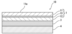
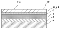
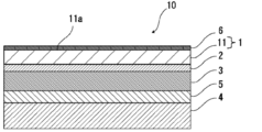
- a battery packaging material 10 of the present invention is composed of a laminate comprising a base layer 1, a barrier layer 3, and a heat-fusible resin layer 4 in this order, as shown in FIG. Is done.
- the base material layer 1 is the outermost layer side
- the heat-fusible resin layer 4 is the innermost layer. That is, when the battery is assembled, the battery element is sealed by heat-sealing the heat-fusible resin layers 4 positioned at the periphery of the battery element to seal the battery element.
- the base material layer 1 should just have the polyester film layer 11 at least, and may be comprised only by the polyester film layer 11 as FIG. 1 shows, and as FIG.
- the polyester film layer 11 and the polyamide film layer 12 may be provided.
- the base material layer 1 is preferably composed only of the polyester film layer 11.
- the base material layer 1 has the polyester film layer 11 and the polyamide film layer 12, as will be described later, either the polyester film layer 11 or the polyamide film layer 12 may be located on the outermost layer side, but the battery From the viewpoint of increasing the electrolytic solution resistance on the outer surface of the packaging material for packaging, it is preferable that the polyamide film layer 12 and the polyester film layer 11 are laminated in order from the barrier layer 3 side.
- the polyester film layer 11 and the polyamide film layer 12 may be laminated so as to be in contact with each other.
- the film layer 12 may be bonded with an adhesive, and an adhesive layer 13 may be provided between these layers.
- the battery packaging material of the present invention includes an adhesive layer 2 between the base material layer 1 and the barrier layer 3 for the purpose of enhancing the adhesion between them. You may have.
- an adhesive layer 5 may be provided between the barrier layer 3 and the heat-fusible resin layer 4 as necessary for the purpose of improving the adhesiveness.
- the surface coating layer 6 etc. may be provided in the outer side (opposite side to the heat-fusible resin layer 4) of the base material layer 1 as needed.
- the thickness of the laminate constituting the battery packaging material of the present invention is not particularly limited. However, from the viewpoint of effectively suppressing curling due to molding while reducing the thickness of the laminate as much as possible, it is preferably about 160 ⁇ m or less, more preferably about 35 to 155 ⁇ m, still more preferably about 45 to 155 ⁇ m, about 100 to 155 ⁇ m, about 120 to 155 ⁇ m. Even when the thickness of the laminate constituting the battery packaging material of the present invention is as thin as 160 ⁇ m or less, for example, according to the present invention, curling due to the molding of the battery packaging material is effectively suppressed.
- the base material layer 1 is a layer located on the outermost layer side.
- the base material layer 1 has at least a polyester film layer 11.
- the base material layer 1 may be comprised only by the polyester film layer 11, and may have the polyester film layer 11 and the polyamide film layer 12.
- the melting peak temperature of the polyester film layer 11 is measured twice by differential scanning calorimetry (DSC), the melting peak temperature P (° C.) measured at the first temperature rise. ) And the melting peak temperature Q (° C.) measured at the second temperature increase (that is, melting peak temperature P (° C.) ⁇ Melting peak temperature Q (° C.)) is larger than 5 ° C.
- a resin film may be used, and you may form by apply
- the base material layer 1 has at least the polyester film layer 11 and the polyester film layer 11 has the specific melting peak temperature difference
- the polyester film is laminated, curling due to the molding of the battery packaging material is suitably suppressed.
- this mechanism can be considered as follows, for example. That is, the difference between the melting peak temperature P (° C.) measured at the first temperature rise and the melting peak temperature Q (° C.) measured at the second temperature rise is larger than 5 ° C., that is, polyester It means that the crystallization of the film layer 11 is large (the amount of crystals is large and the crystals are oriented).
- the melting peak temperature P (° C.) measured at the first time corresponds to the melting peak temperature of the oriented crystal
- the melting peak temperature Q (° C.) measured at the second time is the melting of the non-oriented crystal.
- the melting peak temperature P (° C.) measured at the first time is higher than the melting peak temperature Q (° C.) measured at the second time
- the melting peak temperature P (° C.) measured at the first time is higher than the melting peak temperature Q (° C.) measured at the second time
- the difference (PQ) between the melting peak temperature Q (° C.) measured for the second time and the second time usually does not become a negative value.
- the melting peak temperature difference is measured according to the procedure of JIS K7121: 2012 (Plastic transition temperature measurement method (JIS K7121: 1987 supplement 1)). Specifically, by holding the biaxially stretched polyethylene terephthalate film layer at 0 ° C. for 10 minutes by differential scanning calorimetry (DSC, differential scanning calorimeter Q200 manufactured by TA Instruments), 10 ° C. / The temperature is raised from 0 ° C. to 290 ° C. at a temperature rising rate of 1 minute, the first melting peak temperature P (° C.) is measured, and then held at 290 ° C. for 10 minutes. Next, the temperature is decreased from 290 ° C. to 0 ° C.
- the temperature is raised from 0 ° C. to 290 ° C. at a temperature raising rate of 10 ° C./min, and the second melting peak temperature Q (° C.) is measured.
- the flow rate of nitrogen gas is 50 ml / min.
- the measurement of the melting peak temperature may be performed in the state of a laminate constituting the battery packaging material, or a layer in which a polyester film layer is laminated (for example, the barrier layer 3 or, if necessary). Measurements may be made on the polyester film layer peeled from the laminated polyamide film layer 12).
- the absolute value of the melting peak temperature difference (PQ) may be larger than 5 ° C. by any method.
- the polyester film having the melting peak temperatures P and Q as described above is manufactured by appropriately adjusting, for example, a stretching method, a stretching ratio, a stretching speed, a cooling temperature, a heat setting temperature, and the like when the polyester film is manufactured. Can do. Moreover, a commercial item can be used as such a polyester film.
- the lower limit of the melting peak temperature difference (PQ) is preferably about 6 ° C. or more, and the upper limit is preferably about 20 ° C. or less, more preferably about 15 ° C. or less, and further preferably about 14 ° C. or less.
- a preferable range is greater than 5 ° C. and less than about 20 ° C. Examples include about 14 ° C. or less, about 6 to 20 ° C., about 6 to 15 ° C., and about 6 to 14 ° C.
- the melting peak temperature P (° C.) measured for the first time in the polyester film layer 11 is preferably about 263 ° C. or less, more preferably about 260 ° C. or less, and the lower limit is preferably about 250 ° C. As mentioned above, More preferably, about 253 degreeC or more is mentioned. Preferable ranges of the melting peak temperature P (° C.) include about 250 to 263 ° C., about 250 to 260 ° C., about 253 to 263 ° C., and about 253 to 260 ° C. On the other hand, the melting peak temperature Q (° C.) measured for the second time in the polyester film layer 11 is preferably about 255 ° C. or less, more preferably about 254 ° C.
- the lower limit is preferably about 237 ° C. or higher, more preferably about 238 ° C. or higher.
- a preferable range of the melting peak temperature Q (° C) is about 237 to 255 ° C, about 237 to 254 ° C, about 237 to 252 ° C, about 238 to 255 ° C, about 238 to 254 ° C, or about 238 to 252 ° C. Can be mentioned.
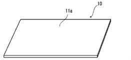
- the arithmetic average roughness Ra on the side opposite to the barrier layer 3 of the polyester film layer constituting the outermost surface 11a is preferably about 1000 nm or less, preferably about the upper limit.
- the lower limit is preferably about 500 nm or less, and the lower limit is preferably about 10 nm or more, more preferably about 20 nm or more, and the preferred range is about 10 to 1000 nm or about 20 to 500 nm.
- the arithmetic average roughness Ra of the polyester film layer has such a value, for example, the printability of the battery packaging material can be improved, and the surface of the polyester film layer can be printed. It can be suitably used as a packaging material.
- the arithmetic average roughness Ra of the polyester film layer constituting the outermost surface 11a on the side opposite to the barrier layer 3 is obtained for the surface of the polyester film layer in accordance with the method defined in JIS B 0601-2001. Value.
- the methods described in the examples can be employed.
- the measurement of the said arithmetic mean roughness Ra of a polyester film layer can be performed in the state laminated
- the arithmetic average roughness Ra of the surface of the polyester film layer can be adjusted by the height and density of the unevenness of the surface of the cooling roll when the polyester film is produced.
- the polyester film layer may contain the following additives (flame retardant, anti-blocking agent, antioxidant, light stabilizer, tackifier, antistatic agent, etc.) as particles.
- the arithmetic average roughness Ra may be adjusted.
- the average particle diameter of the particles is, for example, about 0.1 to 5 ⁇ m, and the content of the particles is, for example, about 0.01 to 0.1% by mass.
- the polyester constituting the polyester film layer 11 is a co-polymer composed mainly of polyethylene terephthalate, polybutylene terephthalate, polyethylene naphthalate, polybutylene naphthalate, polyethylene isophthalate, polycarbonate, and ethylene terephthalate.
- Examples thereof include a polymerized polyester and a copolymerized polyester mainly composed of butylene terephthalate as a repeating unit.
- the copolymer polyester mainly composed of ethylene terephthalate is a copolymer polyester that polymerizes with ethylene isophthalate mainly composed of ethylene terephthalate (hereinafter, polyethylene (terephthalate / isophthalate)).
- polyethylene terephthalate / isophthalate
- polyethylene terephthalate / adipate
- polyethylene terephthalate / sodium sulfoisophthalate
- polyethylene terephthalate / sodium isophthalate
- polyethylene terephthalate / phenyl-dicarboxylate
- polyethylene terephthalate / decanedicarboxylate
- polyester mainly composed of butylene terephthalate as a repeating unit
- a copolymer polyester that polymerizes with butylene isophthalate having butylene terephthalate as a repeating unit hereinafter referred to as polybutylene (terephthalate / isophthalate).
- polybutylene (terephthalate / adipate) polybutylene (terephthalate / sebacate), polybutylene (terephthalate / decanedicarboxylate), polybutylene naphthalate and the like.
- These polyesters may be used individually by 1 type, and may be used in combination of 2 or more type.
- Polyester has the advantage that it is excellent in heat resistance and electrolytic solution resistance, and is less likely to cause whitening due to the adhesion of the electrolytic solution, and is suitably used as a material for forming the base material layer 1.
- the polyester film layer 11 is preferably composed of a biaxially stretched polyester film, particularly a biaxially stretched polyethylene terephthalate film.
- the thickness of the polyester film layer 11 is not particularly limited, but the upper limit is preferably about 35 ⁇ m or less, more preferably about 30 ⁇ m or less, more preferably from the viewpoint of further suitably suppressing curling due to the molding of the battery packaging material.
- the lower limit is preferably about 27 ⁇ m or less, and the lower limit is preferably about 5 ⁇ m or more, more preferably about 8 ⁇ m or more, and still more preferably about 10 ⁇ m or more.
- the preferred range is about 5 to 35 ⁇ m, 5 to 30 ⁇ m. About 5 to 27 ⁇ m, about 8 to 35 ⁇ m, about 8 to 30 ⁇ m, about 8 to 27 ⁇ m, about 10 to 35 ⁇ m, about 10 to 30 ⁇ m, and about 10 to 27 ⁇ m.
- polyamide constituting the polyamide film layer 12 include aliphatic polyamides such as nylon 6, nylon 66, nylon 610, nylon 12, nylon 46, and a copolymer of nylon 6 and nylon 66.
- Hexamethylenediamine-isophthalic acid-terephthalic acid such as nylon 6I, nylon 6T, nylon 6IT, nylon 6I6T (I represents isophthalic acid, T represents terephthalic acid) containing structural units derived from terephthalic acid and / or isophthalic acid Copolyamide, polyamide MXD6 (polymetaxylylene adipamide) and other aromatic polyamides; polyamide PACM6 (polybis (4-aminocyclohexyl) methane adipamide) and other alicyclic polyamides; and lactam component and 4,4 ′ -Diphenylmethane- Polyamides obtained by copolymerization of isocyanate components such as isocyanate, polyesteramide copolymers and polye
- polyamides may be used individually by 1 type, and may be used in combination of 2 or more type.
- the stretched polyamide film is excellent in stretchability, can prevent whitening due to resin cracking of the base material layer 1 during molding, and is suitably used as a material for forming the base material layer 1.
- the polyamide film layer 12 is preferably composed of a biaxially stretched polyamide film, particularly a biaxially stretched nylon film.
- the thickness of the polyamide film layer 12 is not particularly limited, but is preferably about 30 ⁇ m or less, more preferably about 1 to 25 ⁇ m, more preferably from the viewpoint of exhibiting excellent moldability while thinning the battery packaging material. Is about 10 to 25 ⁇ m.
- the ratio of the thickness of the polyester film layer 11 and the thickness of the polyamide film layer 12 is preferably in the range of 1: 1 to 1: 5, more preferably in the range of 1: 1.2 to 1: 4.
- the ratio of the thickness is within such a range, it is easy to balance the stress at the time of forming the battery packaging material, and the battery packaging material can be suitably thinned.
- the stacking order of the polyester film layer 11 and the polyamide film layer 12 is not particularly limited. However, from the viewpoint of improving the electrolytic solution resistance of the battery packaging material, the barrier layer 3 described later is sequentially ordered.
- the polyamide film layer 12 and the polyester film layer 11 are preferably laminated in this order.
- the polyester film layer 11 and the polyamide film layer 12 may be laminated so as to be in contact with each other.
- the adhesive layer 13 may be provided between these layers.
- a method of bonding in a hot melt state such as a co-extrusion method, a sand laminating method, a thermal laminating method and the like can be mentioned.
- the adhesive agent to be used may be a two-component curable adhesive, or a one-component curable adhesive.
- the adhesive is not particularly limited, and may be any of chemical reaction type, solvent volatilization type, heat melting type, hot pressure type, ultraviolet ray curable type, electron beam curable type, and the like.
- a resin composition containing a modified thermoplastic resin graft-modified with an unsaturated carboxylic acid derivative component is preferable.
- the modified thermoplastic resin preferably includes a resin obtained by modifying a polyolefin resin, a styrene elastomer, a polyester elastomer or the like with an unsaturated carboxylic acid derivative component.
- the said resin may be used individually by 1 type, and may be used in combination of 2 or more types.
- the unsaturated carboxylic acid derivative component include unsaturated carboxylic acids, acid anhydrides of unsaturated carboxylic acids, and esters of unsaturated carboxylic acids.
- the unsaturated carboxylic acid derivative component one kind may be used alone, or two or more kinds may be used in combination.
- polyolefin resin in the modified thermoplastic resin examples include low density polyethylene, medium density polyethylene, high density polyethylene; ethylene- ⁇ olefin copolymer; homo, block or random polypropylene; propylene- ⁇ olefin copolymer; Examples include copolymers obtained by copolymerizing polar molecules such as acrylic acid and methacrylic acid; polymers such as crosslinked polyolefins, and the like.
- One type of polyolefin resin may be used alone, or two or more types of combinations may be used.
- styrenic elastomer in the modified thermoplastic resin examples include a copolymer of styrene (hard segment) and butadiene or isoprene or a hydrogenated product (soft segment) thereof.
- One type of polyolefin resin may be used alone, or two or more types of combinations may be used.
- polyester elastomer in the modified thermoplastic resin examples include a copolymer of crystalline polyester (hard segment) and polyalkylene ether glycol (soft segment).
- hard segment crystalline polyester
- soft segment polyalkylene ether glycol
- One type of polyolefin resin may be used alone, or two or more types of combinations may be used.
- Examples of the unsaturated carboxylic acid in the modified thermoplastic resin include acrylic acid, methacrylic acid, maleic acid, fumaric acid, itaconic acid, citraconic acid, tetrahydrophthalic acid, bicyclo [2,2,1] hept-2-ene- Examples include 5,6-dicarboxylic acid.
- Examples of unsaturated carboxylic acid anhydrides include maleic anhydride, itaconic anhydride, citraconic anhydride, tetrahydrophthalic anhydride, bicyclo [2,2,1] hept-2-ene-5,6- And dicarboxylic acid anhydride.
- Examples of the unsaturated carboxylic acid ester include methyl acrylate, methyl methacrylate, ethyl methacrylate, butyl methacrylate, dimethyl maleate, monomethyl maleate, diethyl fumarate, dimethyl itaconate, diethyl citraconic acid, tetrahydro And esters of unsaturated carboxylic acids such as dimethyl phthalic anhydride and dimethyl bicyclo [2,2,1] hept-2-ene-5,6-dicarboxylate.
- modified thermoplastic resin with respect to 100 parts by mass of the base thermoplastic resin, about 0.2 to 100 parts by mass of the unsaturated carboxylic acid derivative component is heated and reacted in the presence of a radical initiator. Can be obtained.
- the reaction temperature is preferably about 50 to 250 ° C, more preferably about 60 to 200 ° C.
- the reaction time depends on the production method, in the case of a melt graft reaction by a twin screw extruder, it is preferably about 2 to 30 minutes, more preferably about 5 to 10 minutes, which is within the residence time of the extruder.
- the denaturation reaction can be carried out under both normal pressure and pressurized conditions.
- the radical initiator used in the modification reaction includes organic peroxides.
- Various materials can be selected as the organic peroxide depending on temperature conditions and reaction time.
- alkyl peroxides aryl peroxides, acyl peroxides, ketone peroxides, peroxyketals, peroxycarbonates, peroxides. Examples thereof include oxyesters and hydroperoxides.
- alkyl peroxides, peroxyketals and peroxyesters are preferable, and di-t-butyl peroxide, 2,5-dimethyl-2,5-di-t- It is more preferable to use butylperoxy-hexyne-3, dicumyl peroxide.
- the thickness of the adhesive layer 13 positioned between the polyester film layer 11 and the polyamide film layer 12 is preferably about 0.1 to 5 ⁇ m, more preferably about 0.5 to 3 ⁇ m.
- the adhesive layer 13 may contain the same colorant as that of the adhesive layer 2 described later.
- the base material layer 1 may further include other layers in addition to the polyester film layer 11 and the polyamide film layer 12 provided as necessary.
- the material for forming the other layers is not particularly limited as long as it has insulating properties. Examples of the material for forming the other layers include polyester, polyamide, epoxy resin, acrylic resin, fluorine resin, polyurethane, silicon resin, phenol resin, polyetherimide, polyimide, and a mixture or copolymer thereof. Etc.
- the thickness of the other layers is preferably about 1 to 20 ⁇ m, more preferably about 1 to 10 ⁇ m.
- a lubricant is present on the surface of the base material layer 1 from the viewpoint of improving the moldability of the battery packaging material. Since the lubricant is present on the surface of the base material layer 1 and the lubricant layer is formed, the moldability of the battery packaging material can be improved while curling due to the molding of the battery packaging material is suppressed. Although it does not restrict
- the amount of the lubricant is not particularly limited, but is preferably about 3 mg / m 2 or more, more preferably 4 to 15 mg / m 2 in an environment of a temperature of 24 ° C. and a relative humidity of 60%.
- about m 2 more preferably about 5 to 14 mg / m 2 is mentioned.
- the base material layer 1 may contain a lubricant. Further, the lubricant present on the surface of the base material layer 1 may be obtained by leaching the lubricant contained in the resin constituting the base material layer 1 or by applying a lubricant to the surface of the base material layer 1. It may be.
- the total thickness of the base material layer 1 is preferably about 4 ⁇ m or more, more preferably 10 to 10 ⁇ m from the viewpoint of making the battery packaging material excellent in insulation while reducing the total thickness of the battery packaging material. It is about 75 ⁇ m, more preferably about 10 to 50 ⁇ m.
- the adhesive layer 2 is a layer provided between the base material layer 1 and the barrier layer 3 as necessary in order to firmly bond them.
- the adhesive layer 2 is formed of an adhesive capable of bonding the base material layer 1 and the barrier layer 3 together.
- the adhesive used for forming the adhesive layer 2 may be a two-component curable adhesive or a one-component curable adhesive.
- the bonding mechanism of the adhesive used for forming the adhesive layer 2 is not particularly limited, and may be any of a chemical reaction type, a solvent volatilization type, a heat melting type, a hot pressure type, and the like.
- adhesive components that can be used to form the adhesive layer 2 include polyester resins such as polyethylene terephthalate, polybutylene terephthalate, polyethylene naphthalate, polybutylene naphthalate, polyethylene isophthalate, and copolyester; polyethers Polyurethane adhesives; epoxy resins; phenol resins; polyamide resins such as nylon 6, nylon 66, nylon 12, copolymer polyamides; polyolefin resins such as polyolefins, acid-modified polyolefins, metal-modified polyolefins, Polyvinyl acetate resin; Cellulose adhesive; (Meth) acrylic resin; Polyimide resin; Polycarbonate; Amino resin such as urea resin and melamine resin; Chloroprene rubber, nitrile rubber, styrene-buta Rubbers such as Engomu; silicone resins. These adhesive components may be used individually by 1 type, and may be used in combination of 2 or more type.
- the polyurethane adhesive is a polyurethane adhesive containing a main component containing a polyol component (A) and a curing agent containing a polyisocyanate component (B), and the polyol component (A) is a polyester polyol ( A1), the polyester polyol (A1) is a polyester polyol having a number average molecular weight of 5,000 to 50,000 and comprising a polybasic acid component and a polyhydric alcohol component, and is aromatic in 100 mol% of the polybasic acid component. Examples include those containing 45 to 95 mol% of a polybasic acid component and having a tensile stress of 100 kg / cm 2 or more and 500 kg / cm 2 or less when the adhesive layer is 100% elongated.
- An equivalent ratio [NCO] / ([OH] + [COOH]) of isocyanate groups contained in the agent is 1 to 30.
- An adhesive containing a resin containing either ((A) or (B)) is also included.
- the adhesive layer 2 may contain a colorant.
- the battery packaging material can be colored.
- the colorant known ones such as pigments and dyes can be used.
- 1 type may be used for a coloring agent, and 2 or more types may be mixed and used for it.
- inorganic pigments preferably include carbon black and titanium oxide.
- organic pigments preferably include azo pigments, phthalocyanine pigments, and condensed polycyclic pigments.
- the azo pigment include soluble pigments such as watching red and carmine 6C; insoluble azo pigments such as monoazo yellow, disazo yellow, pyrazolone orange, pyrazolone red, and permanent red.
- the phthalocyanine pigment include copper phthalocyanine pigment, no pigment
- the metal phthalocyanine pigment include a blue pigment and a green pigment, and examples of the condensed polycyclic pigment include dioxazine violet and quinacridone violet.
- a pearl pigment, a fluorescent pigment, etc. can be used as a pigment, a pearl pigment, a fluorescent pigment, etc.
- carbon black is preferable in order to make the appearance of the battery packaging material black.
- the average particle diameter of the pigment is not particularly limited, and examples thereof include about 0.05 to 5 ⁇ m, preferably about 0.08 to 2 ⁇ m.
- the average particle diameter of a pigment be the median diameter measured with the laser diffraction / scattering type particle size distribution measuring apparatus.
- the content of the pigment in the adhesive layer 2 is not particularly limited as long as the battery packaging material is colored, and examples thereof include about 5 to 60% by mass.
- the thickness of the adhesive layer 2 is not particularly limited as long as it exhibits a function as an adhesive layer, and may be, for example, about 1 ⁇ m or more, preferably about 1 to 10 ⁇ m, more preferably about 2 to 5 ⁇ m.
- the colored layer is a layer provided as necessary between the base material layer 1 and the adhesive layer 2 (illustration is omitted). By providing the colored layer, the battery packaging material can be colored.
- the colored layer can be formed, for example, by applying an ink containing a colorant to the surface of the base material layer 1 or the surface of the barrier layer 3.
- a colorant known ones such as pigments and dyes can be used.
- 1 type may be used for a coloring agent, and 2 or more types may be mixed and used for it.
- colorant contained in the colored layer are the same as those exemplified in the column of [Adhesive layer 2].
- the barrier layer 3 is a layer having a function of preventing water vapor, oxygen, light and the like from entering the battery, in addition to improving the strength of the battery packaging material.
- the barrier layer 3 can be formed of a metal foil, a metal vapor-deposited film, an inorganic oxide vapor-deposited film, a carbon-containing inorganic oxide vapor-deposited film, a film provided with these vapor-deposited layers, or the like, and is a layer formed of metal.
- the metal constituting the barrier layer 3 include aluminum, stainless steel, titanium steel, and preferably aluminum.
- the barrier layer 3 can be formed by, for example, a metal foil, a metal vapor-deposited film, an inorganic oxide vapor-deposited film, a carbon-containing inorganic oxide vapor-deposited film, a film provided with these vapor-deposited films, etc. It is more preferable to form with aluminum foil or stainless steel foil.
- the barrier layer is made of, for example, annealed aluminum (JIS H4160: 1994 A8021H-O, JIS H4160: 1994 A8079H-O, JIS H4000: 2014 A8021P-O, and JIS H4000: 2014 A8079P-O) are more preferable.
- examples of the stainless steel foil include austenitic stainless steel foil and ferritic stainless steel foil.
- the stainless steel foil is preferably made of austenitic stainless steel.
- austenitic stainless steel constituting the stainless steel foil include SUS304, SUS301, SUS316L, and among these, SUS304 is particularly preferable.
- the thickness of the barrier layer 3 is not particularly limited as long as it functions as a barrier layer such as water vapor, and can be appropriately set according to the material constituting the barrier layer 3, and the upper limit is preferably about 85 ⁇ m or less. More preferably, it is about 50 ⁇ m or less, more preferably 40 ⁇ m or less, and the lower limit is preferably about 10 ⁇ m or more.
- the thickness range is, for example, about 10 to 85 ⁇ m, preferably about 10 to 50 ⁇ m. More preferably, it can be about 10 to 45 ⁇ m.
- the thickness of aluminum foil is the said thickness.
- the thickness of the stainless steel foil is particularly preferably about 85 ⁇ m or less, more preferably about 50 ⁇ m or less, still more preferably about 40 ⁇ m or less, and more preferably about 30 ⁇ m or less, particularly preferably about 25 ⁇ m or less is mentioned, the lower limit is about 10 ⁇ m or more, and the preferred thickness range is about 10 to 85 ⁇ m, about 10 to 50 ⁇ m, more preferably about 10 to 40 ⁇ m, more Preferably about 10 to 30 ⁇ m, more preferably about 15 to 25 ⁇ m.
- the barrier layer 3 is preferably subjected to chemical conversion treatment on at least one side, preferably both sides, in order to stabilize adhesion, prevent dissolution and corrosion, and the like.
- the chemical conversion treatment refers to a treatment for forming an acid-resistant film on the surface of the barrier layer.
- the barrier layer 3 includes an acid resistant film.
- chromate chromate using chromic acid compounds such as chromium nitrate, chromium fluoride, chromium sulfate, chromium acetate, chromium oxalate, chromium biphosphate, chromic acetyl acetate, chromium chloride, potassium sulfate chromium, etc.
- X represents a hydrogen atom, a hydroxy group, an alkyl group, a hydroxyalkyl group, an allyl group or a benzyl group.
- R 1 and R 2 are the same or different and each represents a hydroxy group, an alkyl group, or a hydroxyalkyl group.
- examples of the alkyl group represented by X, R 1 and R 2 include a methyl group, an ethyl group, an n-propyl group, an isopropyl group, an n-butyl group, an isobutyl group, Examples thereof include a linear or branched alkyl group having 1 to 4 carbon atoms such as a tert-butyl group.
- Examples of the hydroxyalkyl group represented by X, R 1 and R 2 include a hydroxymethyl group, a 1-hydroxyethyl group, a 2-hydroxyethyl group, a 1-hydroxypropyl group, a 2-hydroxypropyl group, 3- C1-C4 straight or branched chain in which one hydroxy group such as hydroxypropyl group, 1-hydroxybutyl group, 2-hydroxybutyl group, 3-hydroxybutyl group, 4-hydroxybutyl group is substituted
- An alkyl group is mentioned.
- the alkyl group and hydroxyalkyl group represented by X, R 1 and R 2 may be the same or different.
- X is preferably a hydrogen atom, a hydroxy group or a hydroxyalkyl group.
- the number average molecular weight of the aminated phenol polymer having a repeating unit represented by the general formulas (1) to (4) is, for example, preferably 500 to 1,000,000, and more preferably 1,000 to 20,000. .
- a phosphoric acid is coated with a metal oxide such as aluminum oxide, titanium oxide, cerium oxide, tin oxide, or barium sulfate fine particles dispersed therein.
- a method of forming an acid-resistant film on the surface of the barrier layer 3 by performing a baking treatment at 150 ° C. or higher is mentioned.
- a resin layer obtained by crosslinking a cationic polymer with a crosslinking agent may be further formed on the acid resistant film.
- examples of the cationic polymer include polyethyleneimine, an ionic polymer complex composed of a polymer having polyethyleneimine and a carboxylic acid, a primary amine graft acrylic resin obtained by graft polymerization of a primary amine on an acrylic main skeleton, and polyallylamine. Or the derivative, aminophenol, etc. are mentioned.
- these cationic polymers only one type may be used, or two or more types may be used in combination.
- examples of the crosslinking agent include a compound having at least one functional group selected from the group consisting of an isocyanate group, a glycidyl group, a carboxyl group, and an oxazoline group, and a silane coupling agent. As these crosslinking agents, only one type may be used, or two or more types may be used in combination.
- an acid-resistant film for example, as an example, at least the surface on the inner layer side of an aluminum foil (barrier layer) is first subjected to an alkali dipping method, electrolytic cleaning method, acid cleaning method, electrolytic A degreasing treatment is performed by a known treatment method such as an acid cleaning method or an acid activation method, and then a phosphoric acid Cr (chromium) salt, phosphoric acid Ti (titanium) salt, phosphoric acid Zr (zirconium) salt, phosphorus Treatment liquid (aqueous solution) mainly composed of a metal phosphate such as Zn (zinc) salt and a mixture of these metals, or a mixture of a non-metal phosphate and a mixture of these non-metals Treatment liquid (aqueous solution), or a treatment liquid (aqueous solution) composed of a mixture of these with an aqueous synthetic resin such as an acrylic resin, a phenolic resin, or a urethane resin, a
- CrPO 4 chromium phosphate
- AlPO 4 aluminum phosphate
- Al 2 O 3 aluminum oxide
- Al (OH) x water Zn 2 PO 4 ⁇ 4H 2 O (zinc phosphate hydrate) when treated with an acid-resistant film made of aluminum oxide), AlF x (aluminum fluoride), etc.
- AlPO 4 aluminum phosphate
- Al 2 O 3 aluminum oxide
- Al (OH) x aluminum hydroxide
- AlF x aluminum fluoride
- an acid-resistant film for example, at least the surface on the inner layer side of the aluminum foil, first, an alkali dipping method, an electrolytic cleaning method, an acid cleaning method, an electrolytic acid cleaning method, an acid activity
- An acid-resistant film can be formed by performing a degreasing process by a known processing method such as a chemical conversion method and then performing a known anodizing process on the degreasing surface.
- acid-resistant films include films of phosphorus compounds (for example, phosphates) and chromium compounds (chromates).
- phosphorus compounds for example, phosphates
- chromium compounds chromates
- examples of the phosphate system include zinc phosphate, iron phosphate, manganese phosphate, calcium phosphate, and chromium phosphate.
- examples of the chromic acid system include chromium chromate.
- an acid-resistant film by forming an acid-resistant film such as phosphate, chromate, fluoride, triazine thiol compound, between the aluminum and the base material layer at the time of embossing molding
- an acid-resistant film such as phosphate, chromate, fluoride, triazine thiol compound
- hydrogen fluoride generated by the reaction between electrolyte and moisture prevents dissolution and corrosion of the aluminum surface, especially the dissolution and corrosion of aluminum oxide present on the aluminum surface, and adhesion of the aluminum surface This improves the wettability and prevents delamination between the base material layer and aluminum at the time of heat sealing.
- embossed type it shows the effect of preventing delamination between the base material layer and aluminum at the time of press molding.
- an aqueous solution composed of three components of a phenolic resin, a chromium fluoride (3) compound, and phosphoric acid is applied to the aluminum surface, and the dry baking treatment is good.
- the acid-resistant film includes a layer having cerium oxide, phosphoric acid or phosphate, an anionic polymer, and a crosslinking agent that crosslinks the anionic polymer, and the phosphoric acid or phosphate is 1 to 100 parts by mass may be blended with 100 parts by mass of cerium oxide. It is preferable that the acid-resistant film has a multilayer structure further including a layer having a cationic polymer and a crosslinking agent for crosslinking the cationic polymer.
- the anionic polymer is poly (meth) acrylic acid or a salt thereof, or a copolymer containing (meth) acrylic acid or a salt thereof as a main component.
- the said crosslinking agent is at least 1 sort (s) chosen from the group which has a functional group in any one of an isocyanate group, a glycidyl group, a carboxyl group, and an oxazoline group, and a silane coupling agent.
- the phosphoric acid or phosphate is preferably condensed phosphoric acid or condensed phosphate.
- chemical conversion treatment only one type of chemical conversion treatment may be performed, or two or more types of chemical conversion processing may be performed in combination. Furthermore, these chemical conversion treatments may be carried out using one kind of compound alone, or may be carried out using a combination of two or more kinds of compounds.
- chemical conversion treatments chromic acid chromate treatment, chromate treatment combining a chromic acid compound, a phosphoric acid compound, and an aminated phenol polymer are preferable.
- the acid-resistant film include those containing at least one of a phosphorus compound (such as phosphate), a chromium compound (chromate), a fluoride, and a triazine thiol compound.
- a phosphorus compound such as phosphate
- chromate chromium compound
- fluoride a fluoride
- a triazine thiol compound an acid resistant film containing a cerium compound is also preferable.
- cerium compound cerium oxide is preferable.
- the acid resistant film examples include a phosphate film, a chromate film, a fluoride film, and a triazine thiol compound film.
- a phosphate film examples include a phosphate film, a chromate film, a fluoride film, and a triazine thiol compound film.
- an acid-resistant film one of these may be used, or a plurality of combinations may be used.
- a treatment liquid composed of a mixture of a metal phosphate and an aqueous synthetic resin, or a mixture of a non-metal phosphate and an aqueous synthetic resin It may be formed with a treatment liquid.
- the composition of the acid resistant film can be analyzed using, for example, time-of-flight secondary ion mass spectrometry.
- time-of-flight secondary ion mass spectrometry for example, at least one secondary ion composed of Ce, P and O (for example, Ce 2 PO 4 + , CePO 4 ⁇ , etc.) ) Or a peak derived from a secondary ion composed of Cr, P, and O (for example, at least one kind of CrPO 2 + , CrPO 4 ⁇ , etc.) is detected.
- the amount of the acid-resistant film to be formed on the surface of the barrier layer 3 in the chemical conversion treatment is not particularly limited.
- a chromic acid compound is present per 1 m 2 of the surface of the barrier layer 3.
- the thickness of the acid-resistant film is not particularly limited, but is preferably about 1 nm to 20 ⁇ m, more preferably 1 to 1 in terms of the cohesive strength of the film and the adhesion with the barrier layer 3 and the heat-fusible resin layer 4.
- the thickness is about 100 nm, more preferably about 1 to 50 nm.
- the thickness of the acid-resistant film can be measured by observation with a transmission electron microscope, or a combination of observation with a transmission electron microscope and energy dispersive X-ray spectroscopy or electron energy loss spectroscopy.
- the temperature of the barrier layer is increased. It is performed by heating to 70 to 200 ° C.
- the barrier layer 3 may be previously subjected to a degreasing treatment by an alkali dipping method, an electrolytic cleaning method, an acid cleaning method, an electrolytic acid cleaning method, or the like. By performing the degreasing process in this manner, it is possible to more efficiently perform the chemical conversion process on the surface of the barrier layer 3.
- the heat-fusible resin layer 4 corresponds to the innermost layer, and is a layer that heat-fuses the heat-fusible resin layers and seals the battery element when the battery is assembled.
- the resin component used for the heat-fusible resin layer 4 is not particularly limited as long as it can be heat-sealed, and examples thereof include polyolefin, cyclic polyolefin, acid-modified polyolefin, and acid-modified cyclic polyolefin. That is, the resin constituting the heat-fusible resin layer 4 may or may not include a polyolefin skeleton, and preferably includes a polyolefin skeleton.
- the fact that the resin constituting the heat-fusible resin layer 4 contains a polyolefin skeleton can be analyzed by, for example, infrared spectroscopy, gas chromatography mass spectrometry, etc., and the analysis method is not particularly limited.
- a peak derived from maleic acid is detected in the vicinity of the wave number of 1760 cm -1 and near the wave number 1780 cm -1.
- the peak may be small and may not be detected. In that case, it can be analyzed by nuclear magnetic resonance spectroscopy.
- polystyrene resin examples include polyethylene such as low density polyethylene, medium density polyethylene, high density polyethylene, and linear low density polyethylene; homopolypropylene, polypropylene block copolymer (for example, block copolymer of propylene and ethylene), polypropylene And a random copolymer (eg, a random copolymer of propylene and ethylene); an ethylene-butene-propylene terpolymer; and the like.
- polyethylene and polypropylene are preferable.
- the cyclic polyolefin is a copolymer of an olefin and a cyclic monomer
- examples of the olefin that is a constituent monomer of the cyclic polyolefin include ethylene, propylene, 4-methyl-1-pentene, styrene, butadiene, and isoprene. Is mentioned.
- Examples of the cyclic monomer that is a constituent monomer of the cyclic polyolefin include cyclic alkenes such as norbornene; specifically, cyclic dienes such as cyclopentadiene, dicyclopentadiene, cyclohexadiene, and norbornadiene.
- cyclic alkene is preferable, and norbornene is more preferable.
- the acid-modified polyolefin is a polymer modified by block polymerization or graft polymerization of the polyolefin with an acid component.
- the acid component used for modification include carboxylic acids such as maleic acid, acrylic acid, itaconic acid, crotonic acid, maleic anhydride, and itaconic anhydride.
- the acid-modified cyclic polyolefin is obtained by copolymerizing a part of the monomer constituting the cyclic polyolefin in place of the ⁇ , ⁇ -unsaturated carboxylic acid or its anhydride, or by ⁇ , ⁇ - It is a polymer obtained by block polymerization or graft polymerization of an unsaturated carboxylic acid or its anhydride.
- the cyclic polyolefin to be acid-modified is the same as described above.
- the acid component used for modification is the same as that used for modification of the polyolefin.
- acid-modified polyolefin is preferable; acid-modified polypropylene is more preferable.
- the heat-fusible resin layer 4 may be formed of one kind of resin component alone or may be formed of a blend polymer in which two or more kinds of resin components are combined. Furthermore, the heat-fusible resin layer 4 may be formed of only one layer, but may be formed of two or more layers using the same or different resin components.
- a lubricant is preferably present on the surface of the heat-fusible resin layer 4 from the viewpoint of improving the moldability of the battery packaging material. Since the lubricant exists on the surface of the heat-fusible resin layer 4 and the lubricant layer is formed, the moldability of the battery packaging material can be improved while curling due to the molding of the battery packaging material is suppressed. .
- the lubricant is not particularly limited, and a known lubricant can be used. One type of lubricant may be used alone, or two or more types may be used in combination.
- the lubricant is not particularly limited, but preferably an amide lubricant.
- Specific examples of the lubricant include saturated fatty acid amide, unsaturated fatty acid amide, substituted amide, methylol amide, saturated fatty acid bisamide, unsaturated fatty acid bisamide and the like.
- Specific examples of the saturated fatty acid amide include lauric acid amide, palmitic acid amide, stearic acid amide, behenic acid amide, hydroxy stearic acid amide and the like.
- Specific examples of the unsaturated fatty acid amide include oleic acid amide and erucic acid amide.
- substituted amide examples include N-oleyl palmitic acid amide, N-stearyl stearic acid amide, N-stearyl oleic acid amide, N-oleyl stearic acid amide, N-stearyl erucic acid amide and the like.
- methylolamide examples include methylol stearamide.
- saturated fatty acid bisamides include methylene bis stearamide, ethylene biscapric amide, ethylene bis lauric acid amide, ethylene bis stearic acid amide, ethylene bishydroxy stearic acid amide, ethylene bisbehenic acid amide, hexamethylene bis stearic acid amide.
- acid amide hexamethylene bisbehenic acid amide, hexamethylene hydroxystearic acid amide, N, N′-distearyl adipic acid amide, N, N′-distearyl sebacic acid amide, and the like.
- unsaturated fatty acid bisamides include ethylene bisoleic acid amide, ethylene biserucic acid amide, hexamethylene bisoleic acid amide, N, N′-dioleyl adipic acid amide, N, N′-dioleyl sebacic acid amide Etc.
- Specific examples of the fatty acid ester amide include stearoamidoethyl stearate.
- aromatic bisamide examples include m-xylylene bis stearic acid amide, m-xylylene bishydroxy stearic acid amide, N, N′-distearyl isophthalic acid amide and the like.
- One type of lubricant may be used alone, or two or more types may be used in combination.
- the amount of lubricant present on the surface of the heat-fusible resin layer 4 is not particularly limited. From the viewpoint of improving the moldability of the electronic packaging material, it is preferably 10 to 10 at a temperature of 24 ° C. and a relative humidity of 60%. About 50 mg / m 2 , more preferably about 15 to 40 mg / m 2 is mentioned.
- the heat-fusible resin layer 4 may contain a lubricant. Further, the lubricant present on the surface of the heat-fusible resin layer 4 may be one in which a lubricant contained in the resin constituting the heat-fusible resin layer 4 is exuded, or the heat-fusible resin layer. 4 may be obtained by applying a lubricant to the surface.
- the thickness of the heat-fusible resin layer 4 can be set according to the presence or absence of the adhesive layer 5, the thickness of the adhesive layer 5, and the like, and particularly if the function as the heat-fusible resin layer is exhibited.
- the upper limit is, for example, about 100 ⁇ m or less, preferably about 85 ⁇ m or less, more preferably 60 ⁇ m or less
- the lower limit is, for example, about 15 ⁇ m or more, preferably 20 ⁇ m or more. Examples thereof include about 15 to 100 ⁇ m, about 15 to 85 ⁇ m, about 15 to 60 ⁇ m, about 20 to 100 ⁇ m, about 20 to 85 ⁇ m, and about 20 to 60 ⁇ m.
- the upper limit of the thickness of the heat-fusible resin layer 4 is preferably about 85 ⁇ m or less, more preferably about 60 ⁇ m or less.
- the lower limit is, for example, about 15 ⁇ m or more, preferably 20 ⁇ m or more, and preferable ranges include about 15 to 85 ⁇ m, about 15 to 60 ⁇ m, about 20 to 85 ⁇ m, and about 20 to 60 ⁇ m.
- the thickness of the heat-fusible resin layer 4 is preferably about 20 ⁇ m or more, more preferably An example is about 35 to 85 ⁇ m.
- the adhesive layer 5 is a layer provided between the barrier layer 3 and the heat-fusible resin layer 4 as necessary in order to firmly bond the barrier layer 3 and the heat-fusible resin layer 4.
- the adhesive layer 5 is formed of a resin capable of bonding the barrier layer 3 and the heat-fusible resin layer 4.
- resin used for forming the adhesive layer 5 polyolefin resins such as polyolefin, cyclic polyolefin, acid-modified polyolefin, and acid-modified cyclic polyolefin exemplified in the above-described heat-fusible resin layer 4 can be preferably used.
- polyolefin resin polypropylene resins such as polypropylene, cyclic polypropylene, acid-modified polypropylene, and acid-modified cyclic polypropylene can be suitably used.
- the heat-fusible resin layer 4 and the adhesive layer 5 can be suitably formed by extrusion molding.
- the same adhesive as exemplified in the adhesive layer 2 can be used.
- the polyolefin resin is preferably a polyolefin and an acid-modified polyolefin, and particularly preferably polypropylene and an acid-modified polypropylene. That is, the resin constituting the adhesive layer 5 may or may not include a polyolefin skeleton, and preferably includes a polyolefin skeleton.
- the fact that the resin constituting the adhesive layer 5 contains a polyolefin skeleton can be analyzed by, for example, infrared spectroscopy, gas chromatography mass spectrometry, etc., and the analysis method is not particularly limited.
- a peak derived from maleic acid is detected in the vicinity of the wave number of 1760 cm -1 and near the wave number 1780 cm -1.
- the peak may be small and may not be detected. In that case, it can be analyzed by nuclear magnetic resonance spectroscopy.
- the adhesive layer 5 preferably contains an acid-modified polyolefin.
- the acid-modified polyolefin is a polymer modified by block polymerization or graft polymerization of polyolefin with an acid component such as carboxylic acid.
- the acid component used for modification include carboxylic acids such as maleic acid, acrylic acid, itaconic acid, crotonic acid, maleic anhydride, and itaconic anhydride, or anhydrides thereof.
- Polyolefins to be modified include polyethylenes such as low density polyethylene, medium density polyethylene, high density polyethylene, and linear low density polyethylene; homopolypropylene, polypropylene block copolymers (for example, block copolymers of propylene and ethylene), polypropylene Polypropylenes such as random copolymers (eg, random copolymers of propylene and ethylene); ethylene-butene-propylene terpolymers and the like.
- polyethylene and polypropylene are preferable.
- maleic anhydride-modified polyolefin and more preferably maleic anhydride-modified polypropylene are preferable.
- the adhesive layer 5 is a cured resin composition containing an acid-modified polyolefin and a curing agent. More preferably, it is a product.
- Preferred examples of the acid-modified polyolefin include those described above.
- the adhesive layer 5 is a cured product of a resin composition containing an acid-modified polyolefin and at least one selected from the group consisting of a compound having an isocyanate group, a compound having an oxazoline group, and a compound having an epoxy group.
- the resin composition is preferably a cured product of a resin composition containing an acid-modified polyolefin and at least one selected from the group consisting of a compound having an isocyanate group and a compound having an epoxy group.
- the adhesive layer 5 preferably contains at least one selected from the group consisting of urethane resins, ester resins, and epoxy resins, and more preferably contains urethane resins and epoxy resins.
- ester resin for example, an amide ester resin is preferable.
- Amide ester resins are generally formed by the reaction of carboxyl groups and oxazoline groups.
- the adhesive layer 5 is more preferably a cured product of a resin composition containing at least one of these resins and the acid-modified polyolefin.
- the presence of the unreacted material is, for example, infrared spectroscopy, It can be confirmed by a method selected from Raman spectroscopy, time-of-flight secondary ion mass spectrometry (TOF-SIMS) and the like.
- the curing agent having a heterocyclic ring include a curing agent having an oxazoline group and a curing agent having an epoxy group.
- the curing agent having a C ⁇ N bond include a curing agent having an oxazoline group and a curing agent having an isocyanate group.
- the curing agent having a C—O—C bond examples include a curing agent having an oxazoline group, a curing agent having an epoxy group, and a urethane resin.
- the adhesive layer 5 is a cured product of a resin composition containing these curing agents, for example, gas chromatography mass spectrometry (GCMS), infrared spectroscopy (IR), time-of-flight secondary ion mass spectrometry (TOF) -SIMS) and X-ray photoelectron spectroscopy (XPS).
- GCMS gas chromatography mass spectrometry
- IR infrared spectroscopy
- TOF time-of-flight secondary ion mass spectrometry
- XPS X-ray photoelectron spectroscopy
- the compound having an isocyanate group is not particularly limited, but a polyfunctional isocyanate compound is preferably used from the viewpoint of effectively enhancing the adhesion between the acid-resistant film and the adhesive layer 5.
- the polyfunctional isocyanate compound is not particularly limited as long as it is a compound having two or more isocyanate groups.
- Specific examples of the polyfunctional isocyanate-based curing agent include pentane diisocyanate (PDI), isophorone diisocyanate (IPDI), hexamethylene diisocyanate (HDI), tolylene diisocyanate (TDI), diphenylmethane diisocyanate (MDI), and polymerization and nurate of these. And a mixture thereof and a copolymer with another polymer.
- the content of the compound having an isocyanate group in the adhesive layer 5 is preferably in the range of 0.1 to 50% by mass in the resin composition constituting the adhesive layer 5, and preferably 0.5 to 40% by mass. More preferably, it is in the range.
- the compound having an oxazoline group is not particularly limited as long as it is a compound having an oxazoline skeleton.
- Specific examples of the compound having an oxazoline group include those having a polystyrene main chain and those having an acrylic main chain.
- the Epocross series by Nippon Shokubai Co., Ltd. etc. are mentioned, for example.
- the ratio of the compound having an oxazoline group in the adhesive layer 5 is preferably in the range of 0.1 to 50% by mass, and in the range of 0.5 to 40% by mass in the resin composition constituting the adhesive layer 5. More preferably. Thereby, the adhesiveness of the barrier layer 3 (or acid-resistant film
- the epoxy resin is not particularly limited as long as it is a resin capable of forming a crosslinked structure with an epoxy group present in the molecule, and a known epoxy resin can be used.
- the weight average molecular weight of the epoxy resin is preferably about 50 to 2000, more preferably about 100 to 1000, and still more preferably about 200 to 800.
- the weight average molecular weight of the epoxy resin is a value measured by gel permeation chromatography (GPC) measured under conditions using polystyrene as a standard sample.
- epoxy resin examples include trimethylolpropane glycidyl ether derivative, bisphenol A diglycidyl ether, modified bisphenol A diglycidyl ether, novolac glycidyl ether, glycerin polyglycidyl ether, polyglycerin polyglycidyl ether, and the like.
- An epoxy resin may be used individually by 1 type, and may be used in combination of 2 or more types.
- the proportion of the epoxy resin in the adhesive layer 5 is preferably in the range of 0.1 to 50% by mass and preferably in the range of 0.5 to 40% by mass in the resin composition constituting the adhesive layer 5. Is more preferable. Thereby, the adhesiveness of the barrier layer 3 (or acid-resistant film
- the adhesive layer 5 is a cured resin composition containing at least one selected from the group consisting of a compound having an isocyanate group, a compound having an oxazoline group, and an epoxy resin, and the acid-modified polyolefin.
- the acid-modified polyolefin functions as a main agent, and the compound having an isocyanate group, the compound having an oxazoline group, and the epoxy resin each function as a curing agent.
- the thickness of the adhesive layer 5 is preferably about 30 ⁇ m or less, more preferably about 20 ⁇ m or less, more preferably about 5 ⁇ m or less, and the lower limit is about 0.1 ⁇ m or more, about 0.5 ⁇ m or more,
- the thickness ranges are preferably about 0.1 to 30 ⁇ m, about 0.1 to 20 ⁇ m, about 0.1 to 5 ⁇ m, about 0.5 to 30 ⁇ m, about 0.5 to 20 ⁇ m, 0.5 to For example, about 5 ⁇ m.
- the carbodiimide curing agent is not particularly limited as long as it is a compound having at least one carbodiimide group (—N ⁇ C ⁇ N—).
- a polycarbodiimide compound having at least two carbodiimide groups is preferable.
- the curing agent may be composed of two or more kinds of compounds.
- the content of the curing agent in the resin composition forming the adhesive layer 5 is preferably in the range of about 0.1 to 50% by mass, more preferably in the range of about 0.1 to 30% by mass, More preferably, it is in the range of about 0.1 to 10% by mass.
- the adhesive layer 5 can be suitably formed using, for example, an adhesive.
- an adhesive for example, a non-crystalline polyolefin resin (A) having a carboxyl group, a polyfunctional isocyanate compound (B), and a tertiary amine having no functional group that reacts with the polyfunctional isocyanate compound (B) ( C), the polyfunctional isocyanate compound (B) is contained in an amount of 0.3 to 10 mol of the isocyanate group with respect to 1 mol of the total carboxyl groups, and 1 mol of the total carboxyl groups. And the one formed from the adhesive composition containing the tertiary amine (C) in the range of 1 to 10 mol.
- a styrene-type thermoplastic elastomer (A), a tackifier (B), and a polyisocyanate (C) are contained, and a styrene-type thermoplastic elastomer (A) and a tackifier (B And 20 to 90% by weight of the styrenic thermoplastic elastomer (A) and 10 to 80% by weight of the tackifier (B), and the styrenic thermoplastic elastomer (A) 0.003 to 0.04 mmol / g of active hydrogen derived from an amino group or hydroxyl group, and the tackifier (B) with respect to 1 mol of the active hydrogen derived from the styrenic thermoplastic elastomer (A)
- the active hydrogen derived from the functional group is 0 to 15 mol
- the polyisocyanate (C) is derived from the active hydrogen derived from the styrenic thermoplastic elastomer
- the thickness of the adhesive layer 5 is not particularly limited as long as it exhibits the function as an adhesive layer, but the lower limit is preferably about 2 ⁇ m or more, about 10 ⁇ m or more, about 13 ⁇ m or more, about 15 ⁇ m or more, about 20 ⁇ m or more.
- the upper limit is about 50 ⁇ m or less and about 45 ⁇ m or less. Preferred ranges are about 2 to 50 ⁇ m, about 10 to 50 ⁇ m, about 13 to 50 ⁇ m, about 15 to 50 ⁇ m, about 20 to 50 ⁇ m, and about 2 to 45 ⁇ m. And about 10 to 45 ⁇ m, about 13 to 45 ⁇ m, about 15 to 45 ⁇ m, and about 20 to 45 ⁇ m.
- the adhesive layer 5 it is preferable to use a polyolefin resin such as a polyolefin resin exemplified in the heat-fusible resin layer 4 or an acid-modified polyolefin resin.
- the thickness of the adhesive layer is about It is preferably 10 ⁇ m or more and about 20 ⁇ m or more, and the upper limit is particularly preferably about 50 ⁇ m or less.
- the adhesive exemplified in the adhesive layer 2 can also be used. In this case, the thickness of the adhesive layer is preferably about 2 to 10 ⁇ m and about 2 to 5 ⁇ m.
- a cured product of an acid-modified polyolefin and a curing agent it is preferably about 30 ⁇ m or less, more preferably about 0.1 to 20 ⁇ m, and still more preferably about 0.5 to 5 ⁇ m.
- the thickness after drying and curing is about 1 to 30 g / m 2 .
- the base material layer 1 (barrier layer of the base material layer 1) is optionally formed. If necessary, a surface coating layer 6 may be provided on the side opposite to (3).
- the surface coating layer 6 is a layer located in the outermost layer when the battery is assembled.
- the surface coating layer 6 can be formed of, for example, polyvinylidene chloride, a polyester resin, a urethane resin, an acrylic resin, an epoxy resin, or the like. Of these, the surface coating layer 6 is preferably formed of a two-component curable resin. Examples of the two-component curable resin for forming the surface coating layer 6 include a two-component curable urethane resin, a two-component curable polyester resin, and a two-component curable epoxy resin. Moreover, you may mix
- the additive to be added may function as, for example, a matting agent, and the surface coating layer may function as a mat layer.
- Examples of the additive include fine particles having a particle diameter of 0.5 nm to 5 ⁇ m.
- the material of the additive is not particularly limited, and examples thereof include metals, metal oxides, inorganic substances, and organic substances.
- the shape of the additive is not particularly limited, and examples thereof include a spherical shape, a fibrous shape, a plate shape, an indeterminate shape, and a balloon shape.
- Specific additives include talc, silica, graphite, kaolin, montmorilloid, montmorillonite, synthetic mica, hydrotalcite, silica gel, zeolite, aluminum hydroxide, magnesium hydroxide, zinc oxide, magnesium oxide, aluminum oxide, Neodymium oxide, antimony oxide, titanium oxide, cerium oxide, calcium sulfate, barium sulfate, calcium carbonate, calcium silicate, lithium carbonate, calcium benzoate, calcium oxalate, magnesium stearate, alumina, carbon black, carbon nanotubes, high Melting
- money, aluminum, copper, nickel etc. are mentioned.
- additives may be used individually by 1 type, and may be used in combination of 2 or more type.
- silica, barium sulfate, and titanium oxide are preferably used from the viewpoints of dispersion stability and cost.
- the surface of the additive may be subjected to various surface treatments such as insulation treatment and high dispersibility treatment.
- the method for forming the surface coating layer 6 is not particularly limited, and examples thereof include a method in which a two-component curable resin for forming the surface coating layer 6 is applied to one surface of the base material layer 1.
- the additive may be added to the two-component curable resin, mixed, and then applied.
- the thickness of the surface coating layer 6 is not particularly limited as long as the above function as the surface coating layer 6 is exhibited.
- the thickness is about 0.5 to 10 ⁇ m, preferably about 1 to 5 ⁇ m.
- the production method of the battery packaging material of the present invention is not particularly limited as long as a laminate in which layers of a predetermined composition are laminated is obtained. That is, the method for producing a battery packaging material of the present invention includes a step of obtaining a laminate by laminating at least the base material layer, the barrier layer, and the heat-fusible resin layer in this order.
- the melting peak temperature of the polyester film layer is measured by differential scanning calorimetry and has at least a polyester film layer as the base material layer, the melting peak temperature P ( And a difference (PQ) between the melting peak temperature Q (° C.) measured at the second time and a melting peak temperature Q (° C.) larger than 5 ° C. is used.
- a laminate in which the base material layer 1, the adhesive layer 2, and the barrier layer 3 are laminated in this order (hereinafter also referred to as “laminate A”) is formed.
- the laminate A is formed by applying an adhesive used for forming the adhesive layer 2 on the base layer 1 or the barrier layer 3 whose surface is subjected to a chemical conversion treatment, if necessary, a gravure coating method, After applying and drying by a coating method such as a roll coating method, the barrier layer 3 or the base material layer 1 can be laminated and the adhesive layer 2 can be cured by a dry laminating method.
- the adhesive layer 5 and the heat-fusible resin layer 4 are laminated on the barrier layer 3 of the laminate A in this order.
- a method of laminating the adhesive layer 5 and the heat-fusible resin layer 4 on the barrier layer 3 of the laminate A by coextrusion (coextrusion laminating method) (2) a separate adhesive layer 5 And a heat-sealable resin layer 4 laminated, and a method of laminating the laminate on the barrier layer 3 of the laminate A by a thermal laminating method.
- Adhering to the barrier layer 3 of the laminate A An adhesive for forming the layer 5 is formed by extrusion or solution coating, and is laminated at a high temperature by drying or baking, and the heat-fusible resin layer 4 previously formed into a sheet on the adhesive layer 5 is formed. (4) Adhesion while pouring a molten adhesive layer 5 between the barrier layer 3 of the laminate A and the heat-fusible resin layer 4 previously formed into a sheet shape. Laminate A and heat-sealable resin layer 4 are bonded together via layer 5 The method (sandwich lamination method).
- the surface coating layer 6 When the surface coating layer 6 is provided, the surface coating layer 6 is laminated on the surface of the base material layer 1 opposite to the barrier layer 3.
- the surface coating layer 6 can be formed, for example, by applying the above-described resin for forming the surface coating layer 6 to the surface of the base material layer 1.
- the order of the step of laminating the barrier layer 3 on the surface of the base material layer 1 and the step of laminating the surface coating layer 6 on the surface of the base material layer 1 are not particularly limited.
- the barrier layer 3 may be formed on the surface of the base material layer 1 opposite to the surface coating layer 6.
- surface coating layer 6 provided as necessary / base material layer 1 / adhesive layer 2 provided as needed / barrier layer 3 whose surface is subjected to chemical conversion treatment as needed / if necessary
- a hot roll contact type hot air is further formed.
- An example of such heat treatment conditions is 150 to 250 ° C. for 1 to 5 minutes.
- each layer constituting the laminate improves or stabilizes film forming property, lamination processing, suitability for final product secondary processing (pouching, embossing), etc., as necessary. Therefore, surface activation treatment such as corona treatment, blast treatment, oxidation treatment, ozone treatment may be performed.
- the battery packaging material of the present invention is used in a package for sealing and housing battery elements such as a positive electrode, a negative electrode, and an electrolyte. That is, a battery element including at least a positive electrode, a negative electrode, and an electrolyte can be accommodated in a package formed of the battery packaging material of the present invention to obtain a battery.
- a battery element including at least a positive electrode, a negative electrode, and an electrolyte is formed using the battery packaging material of the present invention, with the metal terminals connected to each of the positive electrode and the negative electrode protruding outward.
- a flange portion region where the heat-fusible resin layers are in contact with each other
- heat-sealing the heat-fusible resin layers of the flange portion to seal the battery
- a battery using the packaging material is provided.
- the battery packaging material of the present invention may be used for either a primary battery or a secondary battery, but is preferably a secondary battery.
- the type of secondary battery to which the battery packaging material of the present invention is applied is not particularly limited.
- a lithium ion battery, a lithium ion polymer battery, a lead storage battery, a nickel-hydrogen storage battery, a nickel-cadmium storage battery, a nickel- Examples include iron storage batteries, nickel / zinc storage batteries, silver oxide / zinc storage batteries, metal-air batteries, multivalent cation batteries, capacitors, capacitors, and the like.
- lithium ion batteries and lithium ion polymer batteries can be cited as suitable applications of the battery packaging material of the present invention.
- the battery packaging material used for large-sized batteries such as a vehicle battery is large in size, and also has a large area of the peripheral edge of the recess, so that the effect of curling on battery productivity is large.
- the battery packaging material of the present invention can be suitably used particularly for large batteries such as a vehicle battery because curling due to molding is effectively suppressed.
- a battery to which the battery packaging material of the present invention can be suitably applied includes a large battery having a battery capacity of 30 Ah or more.
- polyester film of the present invention is a polyester film used for the base material layer 1 of a battery packaging material.
- the polyester film of the present invention has a melting peak temperature P (° C.) measured at the first temperature rise and a second rise. It is characterized in that the difference from the melting peak temperature Q (° C) measured at temperature is greater than 5 ° C.
- the specific configuration (composition, thickness, etc.) of the polyester film of the present invention is the same as the polyester film of the polyester film layer constituting the outermost surface in “2.
- each layer forming battery packaging material Each layer forming battery packaging material”.
- the measurement of the melting peak temperature by the differential scanning calorimetry of a polyester film can be performed only in the state of a polyester film.
- the measurement of the arithmetic average roughness Ra of the polyester film can also be carried out in the state of only the polyester film on the surface which is the outermost surface side of the battery packaging material.
- Example 1 An aluminum foil (JIS H4160: JIS H4160) having an acid-resistant film formed on both sides on a biaxially stretched polyethylene terephthalate film (thickness 25 ⁇ m, having a melting point difference PQ (° C.) described in Table 2) as a base material layer. 1994 A8021H-O, thickness 40 ⁇ m) was laminated by a dry laminating method. Specifically, a two-component curable urethane adhesive (a polyol compound and an aromatic isocyanate compound) is applied to one side of an aluminum foil having an acid-resistant film formed on both sides, and an adhesive layer (after curing) Of 3 ⁇ m in thickness). Subsequently, after laminating the adhesive layer on the aluminum foil and the biaxially stretched polyethylene terephthalate film, an aging treatment was performed to prepare a base material layer / adhesive layer / barrier layer laminate.
- a two-component curable urethane adhesive a polyol compound and an aromatic isocyanate compound
- a polypropylene resin (thickness 25 ⁇ m) as an adhesive layer and polypropylene (thickness 55 ⁇ m) as a heat-fusible resin layer are coextruded.
- the adhesive layer / heat-fusible resin layer was laminated on the barrier layer.
- the obtained laminate is aged and heated to obtain a biaxially stretched polyethylene terephthalate film (25 ⁇ m) / adhesive layer (3 ⁇ m) / barrier layer (40 ⁇ m) / polypropylene-based adhesive layer (25 ⁇ m) / polypropylene ( 55 ⁇ m) was obtained as a battery packaging material laminated in this order.
- Table 1 shows the layer structure of the battery packaging material.
- the erucic acid amide was present as a lubricant on both surfaces of the obtained battery packaging material to form a lubricant layer.
- Example 2 As a base material layer, an aluminum foil (JIS H4160: 1994) in which an acid-resistant film is formed on both sides on a biaxially stretched polyethylene terephthalate film (thickness 12 ⁇ m, having a melting point difference PQ (° C.) described in Table 2). A barrier layer made of A8021H-O (thickness 35 ⁇ m) was laminated by a dry laminating method. Specifically, a two-component curable urethane adhesive (a polyol compound and an aromatic isocyanate compound) is applied to one side of an aluminum foil having an acid-resistant film formed on both sides, and an adhesive layer (after curing) Of 3 ⁇ m in thickness). Subsequently, after laminating the adhesive layer on the aluminum foil and the biaxially stretched polyethylene terephthalate film, an aging treatment was performed to prepare a base material layer / adhesive layer / barrier layer laminate.
- a two-component curable urethane adhesive a polyol compound and an aromatic
- Example 2 As in Example 1, erucic acid amide was present as a lubricant on both surfaces of the obtained battery packaging material to form a lubricant layer.
- Example 3 As a base material layer, a biaxially stretched polyethylene terephthalate film (thickness 12 ⁇ m, having a melting point difference PQ (° C.) shown in Table 2) and a biaxially stretched nylon film (thickness 15 ⁇ m) were laminated by a dry laminating method. A laminated film was prepared. In the laminated film, the biaxially stretched polyethylene terephthalate film and the biaxially stretched nylon film are bonded with a urethane-based adhesive (a thickness after curing is 3 ⁇ m) using a polyol and an isocyanate-based curing agent.
- a urethane-based adhesive a thickness after curing is 3 ⁇ m
- a metal foil composed of an aluminum foil (JIS H4160: 1994 A8021H-O, thickness 40 ⁇ m) provided with an acid-resistant film by subjecting both sides to a chemical conversion treatment on the biaxially stretched nylon film side is dry-laminated.
- Laminated Specifically, a two-component polyurethane adhesive (a polyol compound and an aromatic isocyanate compound) is applied to one surface of an aluminum foil provided with an acid-resistant film, and an adhesive layer (after curing) is applied on the barrier layer. A thickness of 3 ⁇ m) was formed.
- maleic anhydride-modified polypropylene (thickness 40 ⁇ m) as an adhesive layer and random polypropylene (thickness 40 ⁇ m) as a heat-fusible resin layer are coextruded on the barrier layer of the obtained laminate.
- the adhesive layer / heat-fusible resin layer was laminated on the barrier layer.
- the obtained laminate is aged and heated to obtain a biaxially stretched polyethylene terephthalate film (12 ⁇ m) / adhesive (3 ⁇ m) / biaxially stretched nylon film (15 ⁇ m) / adhesive layer (3 ⁇ m) / barrier.
- a battery packaging material in which layer (40 ⁇ m) / maleic anhydride-modified polypropylene (40 ⁇ m) / random polypropylene (40 ⁇ m) was laminated in this order was obtained.
- Table 1 shows the layer structure of the battery packaging material.
- Example 2 As in Example 1, erucic acid amide was present as a lubricant on both surfaces of the obtained battery packaging material to form a lubricant layer.
- Comparative Example 1 A polyethylene terephthalate film and a nylon film were laminated by coextrusion to prepare a biaxially stretched laminated film. Between the biaxially stretched polyethylene terephthalate film (thickness 5 ⁇ m, having a melting point difference PQ (° C.) shown in Table 2) and the biaxially stretched nylon film (thickness 20 ⁇ m) of the laminated film There is an adhesive layer (thickness 1 ⁇ m) composed of a resin based on polyester (polyester elastomer). As for the said laminated
- a barrier layer composed of an aluminum foil JIS H4160: 1994 A8021H-O, thickness 40 ⁇ m
- a two-component polyurethane adhesive polyol compound and aromatic isocyanate compound
- an adhesive layer thickness after curing: 3 ⁇ m
- the biaxially stretched polyethylene terephthalate film / adhesive / A laminate of a barrier layer provided with a biaxially stretched nylon film / adhesive layer / acid-resistant film was prepared.
- an amorphous polyolefin resin having a carboxyl group and an adhesive composed of a polyfunctional isocyanate compound are applied and dried at 100 ° C., and the resulting laminate has a barrier layer side.
- An unstretched polypropylene film (CPP, thickness 80 ⁇ m) was passed between two rolls set at 60 ° C. and bonded, thereby laminating an adhesive layer / heat-sealable resin layer on the barrier layer.
- biaxially stretched polyethylene terephthalate film (5 ⁇ m) / adhesive (1 ⁇ m) / biaxially stretched nylon film (20 ⁇ m) / adhesive layer (3 ⁇ m) / barrier
- a battery packaging material in which a layer (40 ⁇ m) / adhesive layer (2 ⁇ m) / unstretched polypropylene film (80 ⁇ m) was laminated in this order was obtained.
- Table 1 shows the layer structure of the battery packaging material.
- Example 2 As in Example 1, erucic acid amide was present as a lubricant on both surfaces of the obtained battery packaging material to form a lubricant layer.
- Comparative Example 2 As a base material layer, an aluminum foil (JIS H4160: 1994) in which an acid-resistant film is formed on both sides on a biaxially stretched polyethylene terephthalate film (thickness 25 ⁇ m, having a melting point difference PQ (° C.) described in Table 2). A barrier layer made of A8021H-O (thickness 35 ⁇ m) was laminated by a dry laminating method. Specifically, a two-component curable urethane adhesive (a polyol compound and an aromatic isocyanate compound) is applied to one side of an aluminum foil having an acid-resistant film formed on both sides, and an adhesive layer (after curing) Of 3 ⁇ m in thickness). Subsequently, after laminating the adhesive layer on the aluminum foil and the biaxially stretched polyethylene terephthalate film, an aging treatment was performed to prepare a base material layer / adhesive layer / barrier layer laminate.
- a two-component curable urethane adhesive a polyol compound and
- Example 2 As in Example 1, erucic acid amide was present as a lubricant on both surfaces of the obtained battery packaging material to form a lubricant layer.
- Comparative Example 3 As a base material layer, a biaxially stretched polyethylene terephthalate film (thickness 12 ⁇ m, having a melting point difference PQ (° C.) shown in Table 2) and a biaxially stretched nylon film (thickness 15 ⁇ m) were laminated by a dry laminating method. A laminated film was prepared. In the laminated film, the biaxially stretched polyethylene terephthalate film and the biaxially stretched nylon film are bonded with a urethane-based adhesive (a thickness after curing is 3 ⁇ m) using a polyol and an isocyanate-based curing agent.
- a urethane-based adhesive a thickness after curing is 3 ⁇ m
- a metal foil composed of an aluminum foil (JIS H4160: 1994 A8021H-O, thickness 40 ⁇ m) provided with an acid-resistant film by subjecting both sides to a chemical conversion treatment on the biaxially stretched nylon film side is dry-laminated.
- Laminated Specifically, a two-component polyurethane adhesive (a polyol compound and an aromatic isocyanate compound) is applied to one side of an aluminum foil provided with an acid-resistant film, and an adhesive layer (after curing) is applied on the barrier layer. A thickness of 3 ⁇ m) was formed.
- maleic anhydride-modified polypropylene (thickness 40 ⁇ m) as an adhesive layer and random polypropylene (thickness 40 ⁇ m) as a heat-fusible resin layer are coextruded on the barrier layer of the obtained laminate.
- the adhesive layer / heat-fusible resin layer was laminated on the barrier layer.
- the obtained laminate is aged and heated to obtain a biaxially stretched polyethylene terephthalate film (12 ⁇ m) / adhesive (3 ⁇ m) / biaxially stretched nylon film (15 ⁇ m) / adhesive layer (3 ⁇ m) / barrier.
- a battery packaging material in which layer (40 ⁇ m) / maleic anhydride-modified polypropylene (40 ⁇ m) / random polypropylene (40 ⁇ m) was laminated in this order was obtained.
- Table 1 shows the layer structure of the battery packaging material.
- Example 2 As in Example 1, erucic acid amide was present as a lubricant on both surfaces of the obtained battery packaging material to form a lubricant layer.
- the numerical value in parentheses in the layer structure means thickness ( ⁇ m).
- PET is polyethylene terephthalate
- Ny is nylon
- AD is a thermoplastic resin layer
- DL is an adhesive layer formed by a dry laminate method
- ALM is an aluminum foil
- CPP is a heat-melted layer formed from unstretched polypropylene (CPP).
- the adhesive resin layer, PPa means an adhesive layer made of maleic anhydride-modified polypropylene
- PP means a heat-fusible resin layer made of polypropylene
- PP means an adhesive layer made of polypropylene resin.
- each biaxially stretched polyethylene terephthalate film layer as a base material layer was melted by a differential scanning calorimeter (DSC, differential scanning calorimeter Q200 manufactured by TA Instruments). The temperature was measured twice. Specifically, a biaxially stretched polyethylene terephthalate film layer was measured by differential scanning calorimetry (DSC) according to the procedure of JIS K7121: 2012 (plastic transition temperature measurement method (Supplement 1 of JIS K7121: 1987)). After holding at 10 ° C. for 10 minutes, the temperature was raised from 0 ° C. to 290 ° C.
- DSC differential scanning calorimeter
- the first melting peak temperature P (° C.) was measured, and then held at 290 ° C. for 10 minutes. did.
- the temperature was decreased from 290 ° C. to 0 ° C. at a temperature decreasing rate of 10 ° C./min, and held for 10 minutes.
- the temperature was raised from 0 ° C. to 290 ° C. at a rate of temperature increase of 10 ° C./min, and the second melting peak temperature Q (° C.) was measured.
- the flow rate of nitrogen gas was 50 ml / min.
- the melting peak temperatures of the biaxially stretched polyethylene terephthalate film layers of Examples 1 and 2 and Comparative Example 2 were each measured using hydrochloric acid between the biaxially stretched polyethylene terephthalate film of each battery packaging material and the aluminum foil. The measurement was performed after peeling and thoroughly washing the surface of the biaxially stretched polyethylene terephthalate film layer with water and drying at room temperature.
- the melting peak temperatures of the biaxially stretched polyethylene terephthalate film layers of Example 3 and Comparative Examples 1 and 3 are respectively between the biaxially stretched polyethylene terephthalate film and the biaxially stretched nylon film of each battery packaging material. The measurement was performed after peeling off using hydrochloric acid and thoroughly washing the surface of the biaxially stretched polyethylene terephthalate film layer with water and drying at room temperature.
- ⁇ Measurement of arithmetic average roughness Ra of biaxially stretched polyethylene terephthalate film surface The side opposite to the barrier layer of the biaxially stretched polyethylene terephthalate film (polyester film layer) constituting the outermost surface of each battery packaging material obtained in accordance with the method defined in JIS B 0601-2001. Arithmetic average roughness Ra was measured for the surface.
- a white interferometer NewView 7300 manufactured by Zygo was used, and measurement was performed under the conditions of a measuring area of 0.22 mm square (objective lens 50 times, zoom lens 1 time) and tilt correction (Cylinder). Went.
- the arithmetic average roughness Ra was measured in the state of the battery packaging material. In the measurement, an operation such as wiping off the surface of the biaxially stretched polyethylene terephthalate film is not performed. The results are shown in Table 2.
- Corner R2.0 mm, ridgeline R1.0 mm) and a female mold with a clearance of 0.3 mm surface is JIS B 0659-1: 2002 Annex 1
- the test sample is placed on the female mold so that the heat-sealable resin layer side is located on the male mold side, and the molding depth is 31.6 mm (MD) ⁇ 54.5 mm (TD) and the molding depth is 6 mm.
- the test sample is pressed with a presser pressure (surface pressure) of 0.1 MPa. Ete was cold-forming (draw-stage molding).
- the details of the position where the molding is performed are as shown in FIG. As shown in FIG. 8, molding was performed at a position where the shortest distance d between the rectangular shaped portion M and the end portion P of the battery packaging material 10 was 70.5 mm.
- the molding part M indicates the position where the concave part is formed by the mold.
- the battery packaging material 10 after molding is placed on the horizontal plane 20 as shown in FIG. 9, and the maximum value t of the distance in the vertical direction y from the horizontal plane 20 to the end P is curled. It was height.
- the base material layer is at least The melting peak temperature P (° C.) measured at the first temperature rise when the melting peak temperature of the polyester film layer is measured twice by differential scanning calorimetry.
- the difference from the melting peak temperature Q (° C.) measured at the second temperature rise is larger than 5 ° C.
- curling due to the molding of the battery packaging material is preferably suppressed. I understand. In the evaluation of curl by the above molding, if t is 10 mm or more, the productivity may decrease.
Landscapes
- Chemical & Material Sciences (AREA)
- Chemical Kinetics & Catalysis (AREA)
- Electrochemistry (AREA)
- General Chemical & Material Sciences (AREA)
- Organic Chemistry (AREA)
- Sealing Battery Cases Or Jackets (AREA)
- Laminated Bodies (AREA)
- Manufacture Of Macromolecular Shaped Articles (AREA)
Abstract
基材層がポリエステルフィルムを有している電池用包装材料の、成形によるカールを抑制する技術を提供する。 少なくとも、基材層、バリア層、及び熱融着性樹脂層をこの順に備える積層体から構成されており、 前記基材層は、少なくとも、ポリエステルフィルム層を有しており、 示差走査熱量測定により、前記ポリエステルフィルム層の融解ピーク温度を2回測定した場合に、1回目の昇温において測定される融解ピーク温度P(℃)と2回目の昇温において測定される融解ピーク温度Q(℃)との差が、5℃より大きい、電池用包装材料。
Description
本発明は、電池用包装材料、その製造方法、ポリエステルフィルム、及び電池に関する。
従来、様々なタイプの電池が開発されているが、あらゆる電池において、電極や電解質等の電池素子を封止するために包装材料が不可欠な部材になっている。従来、電池用包装材料として金属製の包装材料が多用されていた。
一方、近年、電気自動車、ハイブリッド電気自動車、パソコン、カメラ、携帯電話等の高性能化に伴い、電池には、多様な形状が要求されると共に、薄型化や軽量化が求められている。しかしながら、従来多用されていた金属製の電池用包装材料では、形状の多様化に追従することが困難であり、しかも軽量化にも限界があるという欠点がある。
そこで、近年、多様な形状に加工が容易で、薄型化や軽量化を実現し得る電池用包装材料として、基材/アルミニウム箔層/熱融着性樹脂層が順次積層されたフィルム状の包装材料が提案されている(例えば、特許文献1を参照)。
このようなフィルム状の包装材料においては、一般的に、冷間成形により凹部が形成され、当該凹部によって形成された空間に電極や電解液などの電池素子を配し、熱融着性樹脂層同士を熱融着させることにより、包装材料の内部に電池素子が収容された電池が得られる。
フィルム状の包装材料の基材層には、成形性に優れるポリアミドフィルムが使用されることがある。しかしながら、ポリアミドフィルムは、耐電解液性や耐熱性が不十分となる場合がある。
一方、ポリエステルフィルムは、耐電解液性や耐熱性に優れるため、フィルム状の包装材料の基材層への適用が期待される。
ところが、本発明者らが検討したところ、ポリエステルフィルムを基材層に用いて、基材層、バリア層、及び熱融着性樹脂層を順に積層した電池用包装材料とし、これを成形して電池素子を収容する凹部を形成した場合に、当該凹部の周縁部が、成形によってカール(湾曲)して、電池素子の収容や熱融着性樹脂層の熱融着を阻害し、電池の生産効率を低下させる場合があることが見出された。
例えば、車両用電池などの大型電池に使用される電池用包装材料は、サイズが大きくさらに凹部の周縁部の面積も大きくなるため、電池の生産性に与えるカールの影響が大きいという問題がある。
このような状況下、本発明は、基材層がポリエステルフィルムを有している電池用包装材料の、成形によるカールを抑制する技術を提供することを主な目的とする。
本発明者らは、前記課題を解決すべく、ポリエステルフィルムの積層体を基材層として用いた電池用包装材料において、ポリエステルフィルムに着目して成形カールを低減することについて鋭意検討を行った。その結果、従来の電池用包装材料と比較して、成形カールが格段に抑制された電池用包装材料を提供できることを見出した。具体的には、基材層に用いるポリエステルフィルム層として、示差走査熱量測定により、ポリエステルフィルム層の融解ピーク温度を2回測定した場合に、1回目の昇温において測定される融解ピーク温度P(℃)と、2回目の昇温において測定される融解ピーク温度Q(℃)との差が所定温度を超えると、基材層がポリエステルフィルム層を有するにも拘わらず、成形によるカールが効果的に抑制された電池用包装材料となることを見出した。
本発明は、これらの知見に基づいて、更に検討を重ねることにより完成したものである。即ち、本発明は、下記に掲げる態様の発明を提供する。
項1. 少なくとも、基材層、バリア層、及び熱融着性樹脂層をこの順に備える積層体から構成されており、
前記基材層は、少なくとも、ポリエステルフィルム層を有しており、
示差走査熱量測定により、前記ポリエステルフィルム層の融解ピーク温度を2回測定した場合に、1回目の昇温において測定される融解ピーク温度P(℃)と2回目の昇温において測定される融解ピーク温度Q(℃)との差が、5℃より大きい、電池用包装材料。
項2. 前記バリア層と前記熱融着性樹脂層との間に、接着層を備えており、
前記接着層の厚みが、10μm以上である、項1に記載の電池用包装材料。
項3. JIS B 0601-2001に規定された方法に準拠し、前記ポリエステルフィルム層の前記バリア層とは反対側の表面について測定した算術平均粗さRaが、10nm以上である、項1または2に記載の電池用包装材料。
項4. 少なくとも正極、負極、及び電解質を備えた電池素子が、項1~3のいずれかに記載の電池用包装材料により形成された包装体中に収容されている、電池。
項5. 少なくとも、基材層、バリア層、及び熱融着性樹脂層がこの順となるように積層して積層体を得る工程を備えており、
前記基材層として、少なくとも、ポリエステルフィルム層を有しており、かつ、示差走査熱量測定により、前記ポリエステルフィルム層の融解ピーク温度を2回測定した場合に、1回目の昇温において測定される融解ピーク温度P(℃)と、2回目の昇温において測定される融解ピーク温度Q(℃)との差が、5℃より大きいものを用いる、電池用包装材料の製造方法。
項6. 電池用包装材料の基材層に使用するポリエステルフィルムであって、
示差走査熱量測定により、前記ポリエステルフィルムの融解ピーク温度を2回測定した場合に、1回目の昇温において測定される融解ピーク温度P(℃)と2回目の昇温において測定される融解ピーク温度Q(℃)との差が、5℃より大きい、ポリエステルフィルム。
本発明によれば、基材層がポリエステルフィルムを有している電池用包装材料の、成形によるカールを抑制する技術を提供することができる。また、本発明によれば、電池用包装材料の製造方法、ポリエステルフィルム、及び電池を提供することもできる。
本発明の電池用包装材料は、少なくとも、基材層、バリア層、及び熱融着性樹脂層をこの順に備える積層体から構成されており、基材層は、少なくとも、ポリエステルフィルム層を有しており、示差走査熱量測定により、前記ポリエステルフィルム層の融解ピーク温度を2回測定した場合に、1回目の昇温において測定される融解ピーク温度P(℃)と2回目の昇温において測定される融解ピーク温度Q(℃)との差が、5℃より大きいことを特徴とする。
以下、本発明の電池用包装材料について詳述する。なお、本明細書において、「~」で示される数値範囲は「以上」、「以下」を意味する。例えば、2~15mmとの表記は、2mm以上15mm以下を意味する。
1.電池用包装材料の積層構造
本発明の電池用包装材料10は、例えば図1に示すように、基材層1、バリア層3、及び熱融着性樹脂層4をこの順に備える積層体から構成される。本発明の電池用包装材料において、基材層1が最外層側になり、熱融着性樹脂層4は最内層になる。即ち、電池の組み立て時に、電池素子の周縁に位置する熱融着性樹脂層4同士が熱融着して電池素子を密封することにより、電池素子が封止される。
本発明の電池用包装材料10は、例えば図1に示すように、基材層1、バリア層3、及び熱融着性樹脂層4をこの順に備える積層体から構成される。本発明の電池用包装材料において、基材層1が最外層側になり、熱融着性樹脂層4は最内層になる。即ち、電池の組み立て時に、電池素子の周縁に位置する熱融着性樹脂層4同士が熱融着して電池素子を密封することにより、電池素子が封止される。
基材層1は、少なくとも、ポリエステルフィルム層11を有していればよく、図1に示されるようにポリエステルフィルム層11のみによって構成されていてもよいし、図2,3に示されるように、ポリエステルフィルム層11及びポリアミドフィルム層12を有していてもよい。本発明の電池用包装材料の成形によるカールをより一層効果的に抑制する観点から、基材層1は、ポリエステルフィルム層11のみによって構成されていることが好ましい。
なお、基材層1が、後述の通り、ポリエステルフィルム層11及びポリアミドフィルム層12を有する場合、ポリエステルフィルム層11及びポリアミドフィルム層12のいずれが最外層側に位置していてもよいが、電池用包装材料の外表面における耐電解液性を高める観点などからは、バリア層3側から順に、ポリアミドフィルム層12及びポリエステルフィルム層11が積層されていることが好ましい。
例えば図2に示されるように、ポリエステルフィルム層11とポリアミドフィルム層12とは、互いに接面するように積層されていてもよいし、例えば図3に示されるように、ポリエステルフィルム層11とポリアミドフィルム層12とが接着剤により接着されており、これらの層間に接着剤層13を備えていてもよい。
本発明の電池用包装材料は、例えば図4~6に示すように、基材層1とバリア層3との間に、これらの接着性を高める目的で、必要に応じて接着剤層2を有していてもよい。また、図5,6に示すように、バリア層3と熱融着性樹脂層4との間に、これらの接着性を高める目的で、必要に応じて接着層5を設けてもよい。また、図6に示すように、基材層1の外側(熱融着性樹脂層4とは反対側)には、必要に応じて表面被覆層6などが設けられていてもよい。
本発明の電池用包装材料を構成する積層体の厚みとしては、特に制限されないが、積層体の厚みを可能な限り薄くしつつ、成形によるカールを効果的に抑制する観点からは、好ましくは約160μm以下、より好ましくは35~155μm程度、さらに好ましくは45~155μm程度、100~155μm程度、120~155μm程度が挙げられる。本発明の電池用包装材料を構成する積層体の厚みが、例えば160μm以下と薄い場合にも、本発明によれば、電池用包装材料の成形によるカールが効果的に抑制される。
2.電池用包装材料を形成する各層
[基材層1]
本発明の電池用包装材料において、基材層1は、最外層側に位置する層である。基材層1は、少なくとも、ポリエステルフィルム層11を有している。前記の通り、基材層1は、ポリエステルフィルム層11のみによって構成されていてもよいし、ポリエステルフィルム層11及びポリアミドフィルム層12を有していてもよい。
[基材層1]
本発明の電池用包装材料において、基材層1は、最外層側に位置する層である。基材層1は、少なくとも、ポリエステルフィルム層11を有している。前記の通り、基材層1は、ポリエステルフィルム層11のみによって構成されていてもよいし、ポリエステルフィルム層11及びポリアミドフィルム層12を有していてもよい。
本発明の電池用包装材料においては、示差走査熱量測定(DSC)により、ポリエステルフィルム層11の融解ピーク温度を2回測定した場合に、1回目の昇温において測定される融解ピーク温度P(℃)と、2回目の昇温において測定される融解ピーク温度Q(℃)との差(すなわち、融解ピーク温度P(℃)-融解ピーク温度Q(℃))が、5℃より大きいことを特徴とする。基材層1において、ポリエステルフィルム層11、ポリアミドフィルム層12としては、それぞれ、樹脂フィルムを用いてもよいし、樹脂を塗布して形成してもよい。
本発明の電池用包装材料においては、基材層1が、少なくとも、ポリエステルフィルム層11を有しており、かつ、当該ポリエステルフィルム層11が上記特定の融解ピーク温度差を備えていることから、ポリエステルフィルムが積層されているにも拘わらず、電池用包装材料の成形によるカールが好適に抑制されている。限定的な解釈を望むものではないが、この機序としては、例えば、次のように考えることができる。すなわち、1回目の昇温において測定される融解ピーク温度P(℃)と、2回目の昇温において測定される融解ピーク温度Q(℃)との差が5℃より大きいとは、すなわち、ポリエステルフィルム層11の結晶化が大きい(結晶量が多く、結晶が配向している)ことを意味する。ポリエステルフィルム層11の結晶化が大きいと、分子鎖の運動が制限(拘束)され、ポリエステルフィルムの剛性が増大する。その結果、電池用包装材料の成形部分の周辺の変形が抑制され、本発明の電池用包装材料においては、基材層1がポリエステルフィルムを有しているにも拘わらず、成形によるカールが好適に抑制されていると考えられる。
なお、1回目に測定される融解ピーク温度P(℃)が、配向した結晶の融解ピーク温度に対応し、2回目に測定される融解ピーク温度Q(℃)が、配向していない結晶の融解ピーク温度に対応する。そのため、通常、1回目に測定される融解ピーク温度P(℃)は2回目に測定される融解ピーク温度Q(℃)よりも高い温度となり、1回目に測定される融解ピーク温度P(℃)と2回目に測定される融解ピーク温度Q(℃)との差(P-Q)は、通常、負の値になることはない。
当該融解ピーク温度差(P-Q)は、JIS K7121:2012(プラスチックの転移温度測定方法(JIS K7121:1987の追補1))の手順にて測定する。具体的には、示差走査熱量測定(DSC、ティー・エイ・インスツルメント製の示差走査熱量計Q200)により、2軸延伸ポリエチレンテレフタレートフィルム層を、0℃で10分間保持した後、10℃/分の昇温速度で0℃から290℃まで昇温させて、1回目の融解ピーク温度P(℃)を測定した後、290℃にて10分間保持する。次に、10℃/分の降温速度で290℃から0℃まで降温させて10分間保持する。さらに、10℃/分の昇温速度で0℃から290℃まで昇温させて2回目の融解ピーク温度Q(℃)を測定する。なお、窒素ガスの流量は50ml/分とする。以上の手順によって、1回目に測定される融解ピーク温度P(℃)と、2回目に測定される融解ピーク温度Q(℃)との差(融解ピーク温度P-融解ピーク温度Q)を算出する。ポリエステルフィルム層の融解ピーク温度P(℃)と融解ピーク温度Q(℃)の測定は、電池用包装材料からポリエステルフィルム層を取得して行うことができる。なお、融解ピーク温度の測定は、電池用包装材料を構成する積層体の状態で測定を行ってもよいし、ポリエステルフィルム層が積層されている層(例えば、バリア層3や、必要に応じて積層される前記のポリアミドフィルム層12)から剥離したポリエステルフィルム層について測定を行ってよい。これらの方法によって測定される値が異なる場合、本発明においては、いずれかの方法で前記融解ピーク温度差(P-Q)の絶対値が5℃より大きければよい。
上記のような融解ピーク温度P,Qを備えるポリエステルフィルムは、例えば、ポリエステルフィルムを製造する際の延伸方法、延伸倍率、延伸速度、冷却温度、熱固定温度などを適宜調整することにより製造することができる。また、このようなポリエステルフィルムとしては、市販品を用いることができる。
電池用包装材料の成形によるカールをより一層好適に抑制する観点から、当該融解ピーク温度差(P-Q)の下限については、好ましくは約6℃以上が挙げられ、上限については、好ましくは約20℃以下、より好ましくは約15℃以下、さらに好ましくは約14℃以下が挙げられ、好ましい範囲としては、5℃より大きく約20℃以下、5℃より大きく約15℃以下、5℃より大きく約14℃以下程度、6~20℃程度、6~15℃程度、6~14℃程度が挙げられる。
ポリエステルフィルム層11における1回目に測定される融解ピーク温度P(℃)としては、上限は、好ましくは約263℃以下、より好ましくは約260℃以下が挙げられ、下限は、好ましくは約250℃以上、より好ましくは約253℃以上が挙げられる。当該融解ピーク温度P(℃)の好ましい範囲としては、250~263℃程度、250~260℃程度、253~263℃程度、253~260℃程度が挙げられる。一方、ポリエステルフィルム層11における2回目に測定される融解ピーク温度Q(℃)としては、上限は、好ましくは約255℃以下、より好ましくは約254℃以下、さらに好ましくは252℃以下が挙げられ、下限は、好ましくは約237℃以上、より好ましくは約238℃以上が挙げられる。当該融解ピーク温度Q(℃)の好ましい範囲としては、237~255℃程度、237~254℃程度、237~252℃程度、238~255℃程度、238~254℃程度、238~252℃程度が挙げられる。
また、本発明の電池用包装材料において、最表面11aを構成しているポリエステルフィルム層のバリア層3とは反対側の算術平均粗さRaとしては、上限については、好ましくは約1000nm以下、より好ましくは約500nm以下が挙げられ、下限については、好ましくは約10nm以上、より好ましくは約20nm以上が挙げられ、好ましい範囲については、10~1000nm程度、20~500nm程度が挙げられる。ポリエステルフィルム層の当該算術平均粗さRaがこのような値を有していることにより、例えば、電池用包装材料の印字適性を向上させることができ、ポリエステルフィルム層の表面に印刷を施す電池用包装材料として好適に使用することができる。
最表面11aを構成しているポリエステルフィルム層のバリア層3とは反対側の算術平均粗さRaは、当該ポリエステルフィルム層の表面について、JIS B 0601-2001に規定された方法に準拠して求められた値である。具体的な測定方法については、実施例に記載の方法を採用することができる。なお、ポリエステルフィルム層の当該算術平均粗さRaの測定は、ポリエステルフィルム層の表面が露出した状態であれば、電池用包装材料に積層された状態で行うことができる。
ポリエステルフィルム層の表面の当該算術平均粗さRaは、ポリエステルフィルムを製造する際の冷却ロールの表面の凹凸の高さ、密度などによって調整することができる。また、ポリエステルフィルム層には、後述の添加剤(難燃剤、アンチブロッキング剤、酸化防止剤、光安定剤、粘着付与剤、帯電防止剤等)が粒子として含まれていてもよく、粒子によって前記算術平均粗さRaを調整してもよい。粒子の平均粒子径としては例えば0.1~5μm程度、粒子の含有量としては例えば0.01~0.1質量%程度が挙げられる。
ポリエステルフィルム層11を構成しているポリエステルとしては、具体的には、ポリエチレンテレフタレート、ポリブチレンテレフタレート、ポリエチレンナフタレート、ポリブチレンナフタレート、ポリエチレンイソフタレート、ポリカーボネート、エチレンテレフタレートを繰り返し単位の主体とした共重合ポリエステル、ブチレンテレフタレートを繰り返し単位の主体とした共重合ポリエステル等が挙げられる。また、エチレンテレフタレートを繰り返し単位の主体とした共重合ポリエステルとしては、具体的には、エチレンテレフタレートを繰り返し単位の主体としてエチレンイソフタレートと重合する共重合体ポリエステル(以下、ポリエチレン(テレフタレート/イソフタレート)にならって略す)、ポリエチレン(テレフタレート/イソフタレート)、ポリエチレン(テレフタレート/アジペート)、ポリエチレン(テレフタレート/ナトリウムスルホイソフタレート)、ポリエチレン(テレフタレート/ナトリウムイソフタレート)、ポリエチレン(テレフタレート/フェニル-ジカルボキシレート)、ポリエチレン(テレフタレート/デカンジカルボキシレート)等が挙げられる。また、ブチレンテレフタレートを繰り返し単位の主体とした共重合ポリエステルとしては、具体的には、ブチレンテレフタレートを繰り返し単位の主体としてブチレンイソフタレートと重合する共重合体ポリエステル(以下、ポリブチレン(テレフタレート/イソフタレート)にならって略す)、ポリブチレン(テレフタレート/アジペート)、ポリブチレン(テレフタレート/セバケート)、ポリブチレン(テレフタレート/デカンジカルボキシレート)、ポリブチレンナフタレート等が挙げられる。これらのポリエステルは、1種単独で使用してもよく、また2種以上を組み合わせて使用してもよい。ポリエステルは、耐熱性、耐電解液性に優れ、電解液の付着に対して白化等が発生し難いという利点があり、基材層1の形成素材として好適に使用される。
ポリエステルフィルム層11は、2軸延伸ポリエステルフィルム、特に2軸延伸ポリエチレンテレフタレートフィルムにより構成されていることが好ましい。
ポリエステルフィルム層11の厚みとしては、特に制限されないが、電池用包装材料の成形によるカールをより一層好適に抑制する観点から、上限については、好ましくは約35μm以下、より好ましくは約30μm以下、さらに好ましくは約27μm以下が挙げられ、下限については、好ましくは約5μm以上、より好ましくは約8μm以上、さらに好ましくは約10μm以上程度が挙げられ、好ましい範囲としては、5~35μm程度、5~30μm程度、5~27μm程度、8~35μm程度、8~30μm程度、8~27μm程度、10~35μm程度、10~30μm程度、10~27μm程度が挙げられる。
また、ポリアミドフィルム層12を構成しているポリアミドとしては、具体的には、ナイロン6、ナイロン66、ナイロン610、ナイロン12、ナイロン46、ナイロン6とナイロン66との共重合体等の脂肪族ポリアミド;テレフタル酸及び/又はイソフタル酸に由来する構成単位を含むナイロン6I、ナイロン6T、ナイロン6IT、ナイロン6I6T(Iはイソフタル酸、Tはテレフタル酸を表す)等のヘキサメチレンジアミン-イソフタル酸-テレフタル酸共重合ポリアミド、ポリアミドMXD6(ポリメタキシリレンアジパミド)等の芳香族を含むポリアミド;ポリアミドPACM6(ポリビス(4-アミノシクロヘキシル)メタンアジパミド)等の脂環式ポリアミド;さらにラクタム成分や、4,4’-ジフェニルメタン-ジイソシアネート等のイソシアネート成分を共重合させたポリアミド、共重合ポリアミドとポリエステルやポリアルキレンエーテルグリコールとの共重合体であるポリエステルアミド共重合体やポリエーテルエステルアミド共重合体;これらの共重合体等のポリアミドが挙げられる。これらのポリアミドは、1種単独で使用してもよく、また2種以上を組み合わせて使用してもよい。延伸ポリアミドフィルムは延伸性に優れており、成形時の基材層1の樹脂割れによる白化の発生を防ぐことができ、基材層1の形成素材として好適に使用される。
ポリアミドフィルム層12は、2軸延伸ポリアミドフィルム、特に2軸延伸ナイロンフィルムにより構成されていることが好ましい。
ポリアミドフィルム層12の厚みとしては、特に制限されないが、電池用包装材料を薄型化しつつ、優れた成形性を発揮する観点からは、好ましくは約30μm以下、より好ましくは1~25μm程度、より好ましくは10~25μm程度が挙げられる。
成形性をより向上させる観点からは、基材層1において、ポリエステルフィルム層11の厚みと、ポリアミドフィルム層12の厚みの比(ポリエステルフィルム層11の厚み:ポリアミドフィルム層12の厚み)としては、1:1から1:5の範囲にあることが好ましく、1:1.2から1:4の範囲にあることがより好ましい。当該厚みの比がこのような範囲にあることにより、電池用包装材料の成形時の応力のバランスをとりやすく、電池用包装材料を好適に薄型化できる。
基材層1において、ポリエステルフィルム層11とポリアミドフィルム層12の積層順としては、特に制限されないが、電池用包装材料の耐電解液性を向上させる観点からは、後述のバリア層3側から順に、ポリアミドフィルム層12及びポリエステルフィルム層11がこの順に積層されていることが好ましい。
前述の通り、例えば図2に示されるように、ポリエステルフィルム層11とポリアミドフィルム層12とは、互いに接面するように積層されていてもよいし、例えば図3に示されるように、接着剤により接着され、これらの層の間に接着剤層13を備えていてもよい。接着剤を介さず接着させる場合には、例えば、共押出し法、サンドラミネート法、サーマルラミネート法等の熱溶融状態で接着させる方法が挙げられる。また、接着剤を介して接着させる場合、使用する接着剤は、2液硬化型接着剤であってもよく、また1液硬化型接着剤であってもよい。更に、接着剤についても、特に制限されず、化学反応型、溶剤揮発型、熱溶融型、熱圧型、紫外線硬化型や電子線硬化型等のいずれであってもよい。
ポリエステルフィルム層11とポリアミドフィルム層12とを接着する接着剤としては、好ましくは、不飽和カルボン酸誘導体成分でグラフト変性した変性熱可塑性樹脂を含有する樹脂組成物が挙げられる。当該変性熱可塑性樹脂としては、好ましくは、ポリオレフィン系樹脂、スチレン系エラストマー、ポリエステル系エラストマーなどを不飽和カルボン酸誘導体成分で変性した樹脂が挙げられる。当該樹脂は、1種類単独で使用してもよいし、2種類以上を組み合わせて使用してもよい。また、不飽和カルボン酸誘導体成分としては、不飽和カルボン酸、不飽和カルボン酸の酸無水物、不飽和カルボン酸のエステルなどが挙げられる。不飽和カルボン酸誘導体成分としては、1種類単独で使用してもよいし、2種類以上を組み合わせて使用してもよい。
変性熱可塑性樹脂におけるポリオレフィン系樹脂としては、低密度ポリエチレン、中密度ポリエチレン、高密度ポリエチレン;エチレン-αオレフィン共重合体;ホモ、ブロックまたはランダムポリプロピレン;プロピレン-αオレフィン共重合体;前記の材料にアクリル酸、メタクリル酸などの極性分子を共重合した共重合体;架橋ポリオレフィンなどのポリマーなどが挙げられる。ポリオレフィン系樹脂は、1種類単独であってもよいし、2種類以上の組み合わせであってもよい。
変性熱可塑性樹脂におけるスチレン系エラストマーとしては、スチレン(ハードセグメント)と、ブタジエンまたはイソプレンまたはこれらの水添物(ソフトセグメント)の共重合体などが挙げられる。ポリオレフィン系樹脂は、1種類単独であってもよいし、2種類以上の組み合わせであってもよい。
変性熱可塑性樹脂におけるポリエステル系エラストマーとしては、結晶性ポリエステル(ハードセグメント)と、ポリアルキレンエーテルグリコール(ソフトセグメント)の共重合体などが挙げられる。ポリオレフィン系樹脂は、1種類単独であってもよいし、2種類以上の組み合わせであってもよい。
変性熱可塑性樹脂における不飽和カルボン酸としては、例えば、アクリル酸、メタクリル酸、マレイン酸、フマル酸、イタコン酸、シトラコン酸、テトラヒドロフタル酸、ビシクロ[2,2,1]ヘプト-2-エン-5,6-ジカルボン酸などが挙げられる。また、不飽和カルボン酸の酸無水物としては、例えば、無水マレイン酸、無水イタコン酸、無水シトラコン酸、テトラヒドロ無水フタル酸、ビシクロ[2,2,1]ヘプト-2-エン-5,6-ジカルボン酸無水物などが挙げられる。また、不飽和カルボン酸のエステルとしては、例えば、アクリル酸メチル、メタクリル酸メチル、メタクリル酸エチル、メタクリル酸ブチル、マレイン酸ジメチル、マレイン酸モノメチル、フマル酸ジエチル、イタコン酸ジメチル、シトラコン酸ジエチル、テトラヒドロ無水フタル酸ジメチル、ビシクロ[2,2,1]ヘプト-2-エン-5,6-ジカルボン酸ジメチルなどの不飽和カルボン酸のエステルなどが挙げられる。
前記変性熱可塑性樹脂としては、ベースとなる熱可塑性樹脂100質量部に対して、前記不飽和カルボン酸誘導体成分0.2~100質量部程度を、ラジカル開始剤の存在下に加熱して反応させることで得られる。
反応温度は、50~250℃程度が好ましく、60~200℃程度がより好ましい。反応時間は製造方法にも左右されるが、二軸押出機による溶融グラフト反応の場合、押出機の滞留時間内である2~30分程度が好ましく、5~10分程度がより好ましい。また変性反応は、常圧、加圧いずれの条件下においても実施できる。
前記変性反応において使用されるラジカル開始剤としては、有機過酸化物が挙げられる。有機過酸化物としては、温度条件と反応時間によって種々の材料を選択することができ、例えば、アルキルパーオキサイド、アリールパーオキサイド、アシルパーオキサイド、ケトンパーオキサイド、パーオキシケタール、パーオキシカーボネート、パーオキシエステル、ハイドロパーオキサイドなどが挙げられる。上述した二軸押出機による溶融グラフト反応の場合は、アルキルパーオキサイド、パーオキシケタール、パーオキシエステルが好ましく、ジ-t-ブチルパーオキサイド、2,5-ジメチル-2,5-ジ-t-ブチルペルオキシ-ヘキシン-3、ジクミルペルオキシドを用いることがより好ましい。
ポリエステルフィルム層11及びポリアミドフィルム層12の間に位置する接着剤層13の厚みとしては、好ましくは0.1~5μm程度、より好ましくは0.5~3μm程度が挙げられる。
なお、接着剤層13には、後述の接着剤層2と同様の着色剤を含んでいてもよい。
基材層1は、ポリエステルフィルム層11、必要に応じて設けられるポリアミドフィルム層12に加えて、さらに他の層を備えていてもよい。他の層を形成する素材については、絶縁性を備えるものであることを限度として特に制限されるものではない。他の層を形成する素材としては、例えば、ポリエステル、ポリアミド、エポキシ系樹脂、アクリル系樹脂、フッ素樹脂、ポリウレタン、珪素樹脂、フェノール系樹脂、ポリエーテルイミド、ポリイミド、及びこれらの混合物や共重合物等が挙げられる。他の層を備える場合、他の層の厚みとしては、好ましくは1~20μm程度、より好ましくは1~10μm程度が挙げられる。
本発明において、電池用包装材料の成形性を高める観点からは、基材層1の表面には、滑剤が存在していることが好ましい。基材層1の表面に滑剤が存在し、滑剤層を形成していることにより、電池用包装材料の成形によるカールを抑制しつつ、電池用包装材料の成形性を高めることができる。滑剤としては、特に制限されないが、好ましくは後述の熱融着性樹脂層において例示するアミド系滑剤が挙げられる。
基材層1表面に滑剤が存在する場合、その存在量としては、特に制限されないが、温度24℃、相対湿度60%環境において、好ましくは約3mg/m2以上、より好ましくは4~15mg/m2程度、さらに好ましくは5~14mg/m2程度が挙げられる。
基材層1には、滑剤が含まれていてもよい。また、基材層1の表面に存在する滑剤は、基材層1を構成する樹脂に含まれる滑剤を滲出させたものであってもよいし、基材層1の表面に滑剤を塗布したものであってもよい。
基材層1の全体の厚さとしては、電池用包装材料の総厚みを薄くしつつ、絶縁性に優れた電池用包装材料とする観点からは、好ましくは約4μm以上、より好ましくは10~75μm程度、さらに好ましくは10~50μm程度が挙げられる。
[接着剤層2]
本発明の電池用包装材料において、接着剤層2は、基材層1とバリア層3を強固に接着させるために、必要に応じて、これらの間に設けられる層である。
本発明の電池用包装材料において、接着剤層2は、基材層1とバリア層3を強固に接着させるために、必要に応じて、これらの間に設けられる層である。
接着剤層2は、基材層1とバリア層3とを接着可能である接着剤によって形成される。接着剤層2の形成に使用される接着剤は、2液硬化型接着剤であってもよく、また1液硬化型接着剤であってもよい。更に、接着剤層2の形成に使用される接着剤の接着機構についても、特に制限されず、化学反応型、溶剤揮発型、熱溶融型、熱圧型等のいずれであってもよい。
接着剤層2の形成に使用できる接着成分としては、具体的には、ポリエチレンテレフタレート、ポリブチレンテレフタレート、ポリエチレンナフタレート、ポリブチレンナフタレート、ポリエチレンイソフタレート、共重合ポリエステル等のポリエステル系樹脂;ポリエーテル系接着剤;ポリウレタン系接着剤;エポキシ系樹脂;フェノール系樹脂;ナイロン6、ナイロン66、ナイロン12、共重合ポリアミド等のポリアミド系樹脂;ポリオレフィン、酸変性ポリオレフィン、金属変性ポリオレフィン等のポリオレフィン系樹脂、ポリ酢酸ビニル系樹脂;セルロース系接着剤;(メタ)アクリル系樹脂;ポリイミド系樹脂;ポリカーボネート;尿素樹脂、メラミン樹脂等のアミノ樹脂;クロロプレンゴム、ニトリルゴム、スチレン-ブタジエンゴム等のゴム;シリコーン系樹脂等が挙げられる。これらの接着成分は1種単独で使用してもよく、また2種以上を組み合わせて使用してもよい。これらの接着成分の中でも、好ましくはポリウレタン系接着剤が挙げられる。
ポリウレタン系接着剤としては、ポリオール成分(A)を含有する主剤と、ポリイソシアネート成分(B)を含有する硬化剤とを含有するポリウレタン系接着剤であって、ポリオール成分(A)がポリエステルポリオール(A1)を含有し、ポリエステルポリオール(A1)が多塩基酸成分と多価アルコール成分とから構成される数平均分子量5000~50000のポリエステルポリオールであって、多塩基酸成分100モル%中、芳香族多塩基酸成分を45~95モル%含み、接着剤層の100%伸び時の引張り応力が100kg/cm2以上、500kg/cm2以下となるものが挙げられる。また、主剤とポリイソシアネート硬化剤とを含有する電池用包装材用ポリウレタン系接着剤であって、主剤が、ガラス転移温度が40℃以上のポリエステルポリオール(A1)5~50重量%およびガラス転移温度が40℃未満のポリエステルポリオール(A2)95~50重量%を含むポリオール成分(A)とシランカップリング剤(B)とを含み、ポリオール成分(A)由来のヒドロキシ基とカルボキシル基の合計に対する硬化剤中に含まれるイソシアネート基の当量比[NCO]/([OH]+[COOH])が1~30であるものが挙げられる。
さらに、変性ポリプロピレン及びポリアクリル系樹脂からなる群から選ばれる1種以上の樹脂(A)、または、シラン系カップリング剤及びチタネート系カップリング剤の少なくとも一方を含むカップリング剤(B)のいずれか一方((A)または(B))を含有する樹脂を含む接着剤も挙げられる。
また、接着剤層2は、着色剤を含んでいてもよい。接着剤層2が着色剤を含んでいることにより、電池用包装材料を着色することができる。着色剤としては、顔料、染料などの公知のものが使用できる。また、着色剤は、1種類のみを用いてもよいし、2種類以上を混合して用いてもよい。
例えば、無機系の顔料の具体例としては、好ましくはカーボンブラック、酸化チタンなどが挙げられる。また、有機系の顔料の具体例としては、好ましくはアゾ系顔料、フタロシアニン系顔料、縮合多環系顔料などが挙げられる。アゾ系顔料としては、ウォッチングレッド、カーミン6Cなどの溶性顔料;モノアゾイエロー、ジスアゾイエロー、ピラゾロンオレンジ、ピラゾロンレッド、パーマネントレッド等の不溶性アゾ顔料が挙げられ、フタロシアニン系顔料としては、銅フタロシアニン顔料、無金属フタロシアニン顔料としての青系顔料や緑系顔料が挙げられ、縮合多環系顔料としては、ジオキサジンバイオレット、キナクリドンバイオレットなどが挙げられる。また、顔料としては、パール顔料や、蛍光顔料なども使用できる。
着色剤の中でも、例えば電池用包装材料の外観を黒色とするためには、カーボンブラックが好ましい。
顔料の平均粒子径としては、特に制限されず、例えば、0.05~5μm程度、好ましくは0.08~2μm程度が挙げられる。なお、顔料の平均粒子径は、レーザ回折/散乱式粒子径分布測定装置で測定されたメジアン径とする。
接着剤層2における顔料の含有量としては、電池用包装材料が着色されれば特に制限されず、例えば5~60質量%程度が挙げられる。
接着剤層2の厚みについては、接着層としての機能を発揮すれば特に制限されないが、例えば、約1μm以上、好ましくは1~10μm程度、より好ましくは2~5μm程度が挙げられる。
[着色層]
着色層は、基材層1と接着剤層2との間に必要に応じて設けられる層である(図示を省略する)。着色層を設けることにより、電池用包装材料を着色することができる。
着色層は、基材層1と接着剤層2との間に必要に応じて設けられる層である(図示を省略する)。着色層を設けることにより、電池用包装材料を着色することができる。
着色層は、例えば、着色剤を含むインキを基材層1の表面、またはバリア層3の表面に塗布することにより形成することができる。着色剤としては、顔料、染料などの公知のものが使用できる。また、着色剤は、1種類のみを用いてもよいし、2種類以上を混合して用いてもよい。
着色層に含まれる着色剤の具体例としては、[接着剤層2]の欄で例示したものと同じものが例示される。
[バリア層3]
電池用包装材料において、バリア層3は、電池用包装材料の強度向上の他、電池内部に水蒸気、酸素、光などが侵入することを防止する機能を有する層である。バリア層3は、金属箔、金属蒸着膜、無機酸化物蒸着膜、炭素含有無機酸化物蒸着膜、これらの蒸着層を設けたフィルムなどにより形成することができ、金属で形成されている層であることが好ましい。バリア層3を構成する金属としては、具体的には、アルミニウム、ステンレス鋼、チタン鋼などが挙げられ、好ましくはアルミニウムが挙げられる。バリア層3は、例えば、金属箔や金属蒸着膜、無機酸化物蒸着膜、炭素含有無機酸化物蒸着膜、これらの蒸着膜を設けたフィルムなどにより形成することができ、金属箔により形成することが好ましく、アルミニウム箔又はステンレス鋼箔により形成することがさらに好ましい。
電池用包装材料において、バリア層3は、電池用包装材料の強度向上の他、電池内部に水蒸気、酸素、光などが侵入することを防止する機能を有する層である。バリア層3は、金属箔、金属蒸着膜、無機酸化物蒸着膜、炭素含有無機酸化物蒸着膜、これらの蒸着層を設けたフィルムなどにより形成することができ、金属で形成されている層であることが好ましい。バリア層3を構成する金属としては、具体的には、アルミニウム、ステンレス鋼、チタン鋼などが挙げられ、好ましくはアルミニウムが挙げられる。バリア層3は、例えば、金属箔や金属蒸着膜、無機酸化物蒸着膜、炭素含有無機酸化物蒸着膜、これらの蒸着膜を設けたフィルムなどにより形成することができ、金属箔により形成することが好ましく、アルミニウム箔又はステンレス鋼箔により形成することがさらに好ましい。
電池用包装材料の製造時に、バリア層3にしわやピンホールが発生することを防止する観点からは、バリア層は、例えば、焼きなまし処理済みのアルミニウム(JIS H4160:1994 A8021H-O、JIS H4160:1994 A8079H-O、JIS H4000:2014 A8021P-O、JIS H4000:2014 A8079P-O)など軟質アルミニウム箔により形成することがより好ましい。
また、ステンレス鋼箔としては、オーステナイト系のステンレス鋼箔、フェライト系のステンレス鋼箔などが挙げられる。ステンレス鋼箔は、オーステナイト系のステンレス鋼により構成されていることが好ましい。
ステンレス鋼箔を構成するオーステナイト系のステンレス鋼の具体例としては、SUS304、SUS301、SUS316Lなどが挙げられ、これら中でも、SUS304が特に好ましい。
バリア層3の厚みは、水蒸気などのバリア層としての機能を発揮すれば特に制限されず、バリア層3を構成する素材に応じて適宜設定することができ、上限としては、好ましくは約85μm以下、より好ましくは約50μm以下、さらに好ましくは40μm以下が挙げられ、下限としては、好ましくは約10μm以上が挙げられ、当該厚みの範囲としては、例えば、10~85μm程度、好ましくは10~50μm程度、より好ましくは10~45μm程度とすることができる。なお、バリア層3がアルミニウム箔により構成されている場合には、アルミニウム箔の厚みは前記の厚みであることが特に好ましい。また、バリア層3がステンレス鋼箔により構成されている場合、特に、ステンレス鋼箔の厚みとしては、好ましくは約85μm以下、より好ましくは約50μm以下、さらに好ましくは約40μm以下、さらに好ましくは約30μm以下、特に好ましくは約25μm以下が挙げられ、下限としては、約10μm以上が挙げられ、好ましい厚みの範囲としては、10~85μm程度、10~50μm程度、より好ましくは10~40μm程度、より好ましくは10~30μm程度、さらに好ましくは15~25μm程度が挙げられる。
また、バリア層3は、接着の安定化、溶解や腐食の防止などのために、少なくとも一方の面、好ましくは両面が化成処理されていることが好ましい。ここで、化成処理とは、バリア層の表面に耐酸性皮膜を形成する処理をいう。本発明のバリア層3の表面に耐酸性皮膜が形成されている場合、バリア層3には耐酸性皮膜が含まれる。化成処理としては、例えば、硝酸クロム、フッ化クロム、硫酸クロム、酢酸クロム、蓚酸クロム、重リン酸クロム、クロム酸アセチルアセテート、塩化クロム、硫酸カリウムクロムなどのクロム酸化合物を用いたクロム酸クロメート処理;リン酸ナトリウム、リン酸カリウム、リン酸アンモニウム、ポリリン酸などのリン酸化合物を用いたリン酸クロメート処理;下記一般式(1)~(4)で表される繰り返し単位を有するアミノ化フェノール重合体を用いたクロメート処理などが挙げられる。なお、当該アミノ化フェノール重合体において、下記一般式(1)~(4)で表される繰り返し単位は、1種類単独で含まれていてもよいし、2種類以上の任意の組み合わせであってもよい。

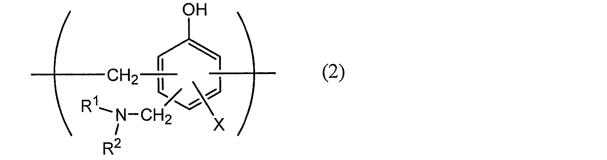
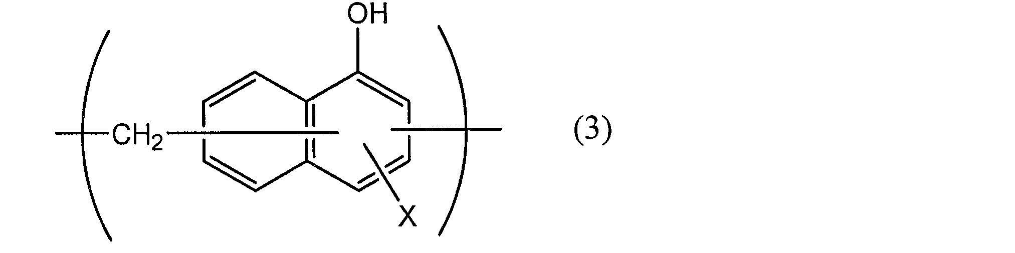
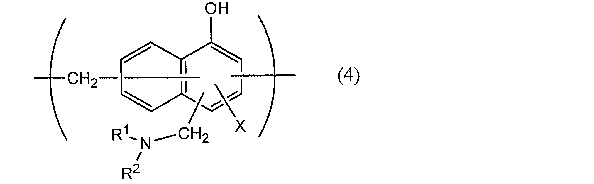
一般式(1)~(4)中、Xは、水素原子、ヒドロキシ基、アルキル基、ヒドロキシアルキル基、アリル基またはベンジル基を示す。また、R1及びR2は、それぞれ同一または異なって、ヒドロキシ基、アルキル基、またはヒドロキシアルキル基を示す。一般式(1)~(4)において、X、R1及びR2で示されるアルキル基としては、例えば、メチル基、エチル基、n-プロピル基、イソプロピル基、n-ブチル基、イソブチル基、tert-ブチル基などの炭素数1~4の直鎖または分枝鎖状アルキル基が挙げられる。また、X、R1及びR2で示されるヒドロキシアルキル基としては、例えば、ヒドロキシメチル基、1-ヒドロキシエチル基、2-ヒドロキシエチル基、1-ヒドロキシプロピル基、2-ヒドロキシプロピル基、3-ヒドロキシプロピル基、1-ヒドロキシブチル基、2-ヒドロキシブチル基、3-ヒドロキシブチル基、4-ヒドロキシブチル基などのヒドロキシ基が1個置換された炭素数1~4の直鎖または分枝鎖状アルキル基が挙げられる。一般式(1)~(4)において、X、R1及びR2で示されるアルキル基及びヒドロキシアルキル基は、それぞれ同一であってもよいし、異なっていてもよい。一般式(1)~(4)において、Xは、水素原子、ヒドロキシ基またはヒドロキシアルキル基であることが好ましい。一般式(1)~(4)で表される繰り返し単位を有するアミノ化フェノール重合体の数平均分子量は、例えば、500~100万であることが好ましく、1000~2万であることがより好ましい。
また、バリア層3に耐食性を付与する化成処理方法として、リン酸中に、酸化アルミニウム、酸化チタン、酸化セリウム、酸化スズなどの金属酸化物や硫酸バリウムの微粒子を分散させたものをコーティングし、150℃以上で焼付け処理を行うことにより、バリア層3の表面に耐酸性皮膜を形成する方法が挙げられる。また、耐酸性皮膜の上には、カチオン性ポリマーを架橋剤で架橋させた樹脂層をさらに形成してもよい。ここで、カチオン性ポリマーとしては、例えば、ポリエチレンイミン、ポリエチレンイミンとカルボン酸を有するポリマーからなるイオン高分子錯体、アクリル主骨格に1級アミンをグラフト重合させた1級アミングラフトアクリル樹脂、ポリアリルアミンまたはその誘導体、アミノフェノールなどが挙げられる。これらのカチオン性ポリマーとしては、1種類のみを用いてもよいし、2種類以上を組み合わせて用いてもよい。また、架橋剤としては、例えば、イソシアネート基、グリシジル基、カルボキシル基、及びオキサゾリン基よりなる群から選ばれた少なくとも1種の官能基を有する化合物、シランカップリング剤などが挙げられる。これらの架橋剤としては、1種類のみを用いてもよいし、2種類以上を組み合わせて用いてもよい。
また、耐酸性皮膜を具体的に設ける方法としては、たとえば、一つの例として、少なくともアルミニウム箔(バリア層)の内層側の面を、まず、アルカリ浸漬法、電解洗浄法、酸洗浄法、電解酸洗浄法、酸活性化法等の周知の処理方法で脱脂処理を行い、その後脱脂処理面にリン酸Cr(クロム)塩、リン酸Ti(チタン)塩、リン酸Zr(ジルコニウム)塩、リン酸Zn(亜鉛)塩などのリン酸金属塩およびこれらの金属塩の混合体を主成分とする処理液(水溶液)、あるいは、リン酸非金属塩およびこれらの非金属塩の混合体を主成分とする処理液(水溶液)、あるいは、これらとアクリル系樹脂ないしフェノール系樹脂ないしウレタン系樹脂等の水系合成樹脂との混合物からなる処理液(水溶液)をロールコート法、グラビア印刷法、浸漬法等の周知の塗工法で塗工することにより、耐酸性皮膜を形成することができる。たとえば、リン酸Cr(クロム)塩系処理液で処理した場合は、CrPO4(リン酸クロム)、AlPO4(リン酸アルミニウム)、Al2O3(酸化アルミニウム)、Al(OH)x(水酸化アルミニウム)、AlFx(フッ化アルミニウム)などからなる耐酸性皮膜となり、リン酸Zn(亜鉛)塩系処理液で処理した場合は、Zn2PO4・4H2O(リン酸亜鉛水和物)、AlPO4(リン酸アルミニウム)、Al2O3(酸化アルミニウム)、Al(OH)x(水酸化アルミニウム)、AlFx(フッ化アルミニウム)などからなる耐酸性皮膜となる。
また、耐酸性皮膜を設ける具体的方法の他の例としては、たとえば、少なくともアルミニウム箔の内層側の面を、まず、アルカリ浸漬法、電解洗浄法、酸洗浄法、電解酸洗浄法、酸活性化法等の周知の処理方法で脱脂処理を行い、その後脱脂処理面に周知の陽極酸化処理を施すことにより、耐酸性皮膜を形成することができる。
また、耐酸性皮膜の他の一例としては、リン化合物(例えばリン酸塩系)、クロム化合物(クロム酸系)の皮膜が挙げられる。リン酸塩系としては、リン酸亜鉛、リン酸鉄、リン酸マンガン、リン酸カルシウム、リン酸クロムなどが挙げられ、クロム酸系としては、クロム酸クロムなどが挙げられる。
また、耐酸性皮膜の他の一例としては、リン酸塩、クロム酸塩、フッ化物、トリアジンチオール化合物等の耐酸性皮膜を形成することによって、エンボス成形時のアルミニウムと基材層との間のデラミネーション防止、電解質と水分とによる反応で生成するフッ化水素により、アルミニウム表面の溶解、腐食、特にアルミニウムの表面に存在する酸化アルミニウムが溶解、腐食することを防止し、かつ、アルミニウム表面の接着性(濡れ性)を向上させ、ヒートシール時の基材層とアルミニウムとのデラミネーション防止、エンボスタイプにおいてはプレス成形時の基材層とアルミニウムとのデラミネーション防止の効果を示す。耐酸性皮膜を形成する物質のなかでも、フェノール系樹脂、フッ化クロム(3)化合物、リン酸の3成分から構成された水溶液をアルミニウム表面に塗布し、乾燥焼付けの処理が良好である。
また、耐酸性皮膜は、酸化セリウムと、リン酸またはリン酸塩と、アニオン性ポリマーと、該アニオン性ポリマーを架橋させる架橋剤とを有する層を含み、前記リン酸またはリン酸塩が、前記酸化セリウム100質量部に対して、1~100質量部配合されていてもよい。耐酸性皮膜が、カチオン性ポリマーおよび該カチオン性ポリマーを架橋させる架橋剤を有する層をさらに含む多層構造であることが好ましい。
さらに、前記アニオン性ポリマーが、ポリ(メタ)アクリル酸またはその塩、あるいは(メタ)アクリル酸またはその塩を主成分とする共重合体であることが好ましい。また、前記架橋剤が、イソシアネート基、グリシジル基、カルボキシル基、オキサゾリン基のいずれかの官能基を有する化合物とシランカップリング剤よりなる群から選ばれる少なくとも1種であることが好ましい。
また、前記リン酸またはリン酸塩が、縮合リン酸または縮合リン酸塩であることが好ましい。
化成処理は、1種類の化成処理のみを行ってもよいし、2種類以上の化成処理を組み合わせて行ってもよい。さらに、これらの化成処理は、1種の化合物を単独で使用して行ってもよく、また2種以上の化合物を組み合わせて使用して行ってもよい。化成処理の中でも、クロム酸クロメート処理や、クロム酸化合物、リン酸化合物、及びアミノ化フェノール重合体を組み合わせたクロメート処理などが好ましい。
耐酸性皮膜の具体例としては、リン化合物(リン酸塩など)、クロム化合物(クロム酸塩)、フッ化物、及びトリアジンチオール化合物のうち少なくとも1種を含むものが挙げられる。また、セリウム化合物を含む耐酸性皮膜も好ましい。セリウム化合物としては、酸化セリウムが好ましい。
また、耐酸性皮膜の具体例としては、リン酸塩系皮膜、クロム酸塩系皮膜、フッ化物系皮膜、トリアジンチオール化合物皮膜なども挙げられる。耐酸性皮膜としては、これらのうち1種類であってもよいし、複数種類の組み合わせであってもよい。さらに、耐酸性皮膜としては、バリア層の化成処理面を脱脂処理した後に、リン酸金属塩と水系合成樹脂との混合物からなる処理液、またはリン酸非金属塩と水系合成樹脂との混合物からなる処理液で形成されたものであってもよい。
なお、耐酸性皮膜の組成の分析は、例えば、飛行時間型2次イオン質量分析法を用いて行うことができる。飛行時間型2次イオン質量分析法を用いた耐酸性皮膜の組成の分析により、例えば、CeとPとOからなる2次イオン(例えば、Ce2PO4
+、CePO4
-などの少なくとも1種)や、例えば、CrとPとOからなる2次イオン(例えば、CrPO2
+、CrPO4
-などの少なくとも1種)に由来するピークが検出される。
化成処理においてバリア層3の表面に形成させる耐酸性皮膜の量については、特に制限されないが、例えば、上記のクロメート処理を行う場合であれば、バリア層3の表面1m2当たり、クロム酸化合物がクロム換算で0.5~50mg程度、好ましくは1.0~40mg程度、リン化合物がリン換算で0.5~50mg程度、好ましくは1.0~40mg程度、及びアミノ化フェノール重合体が1.0~200mg程度、好ましくは5.0~150mg程度の割合で含有されていることが望ましい。
耐酸性皮膜の厚みとしては、特に制限されないが、皮膜の凝集力や、バリア層3や熱融着性樹脂層4との密着力の観点から、好ましくは1nm~20μm程度、より好ましくは1~100nm程度、さらに好ましくは1~50nm程度が挙げられる。なお、耐酸性皮膜の厚みは、透過電子顕微鏡による観察、または、透過電子顕微鏡による観察と、エネルギー分散型X線分光法もしくは電子線エネルギー損失分光法との組み合わせによって測定することができる。
化成処理は、耐酸性皮膜の形成に使用する化合物を含む溶液を、バーコート法、ロールコート法、グラビアコート法、浸漬法などによって、バリア層3の表面に塗布した後に、バリア層の温度が70~200℃になるように加熱することにより行われる。また、バリア層3に化成処理を施す前に、予めバリア層3を、アルカリ浸漬法、電解洗浄法、酸洗浄法、電解酸洗浄法などによる脱脂処理に供してもよい。このように脱脂処理を行うことにより、バリア層3の表面の化成処理をより効率的に行うことが可能となる。
[熱融着性樹脂層4]
本発明の電池用包装材料において、熱融着性樹脂層4は、最内層に該当し、電池の組み立て時に熱融着性樹脂層同士が熱融着して電池素子を密封する層である。
本発明の電池用包装材料において、熱融着性樹脂層4は、最内層に該当し、電池の組み立て時に熱融着性樹脂層同士が熱融着して電池素子を密封する層である。
熱融着性樹脂層4に使用される樹脂成分については、熱融着可能であることを限度として特に制限されないが、例えば、ポリオレフィン、環状ポリオレフィン、酸変性ポリオレフィン、酸変性環状ポリオレフィンが挙げられる。すなわち、熱融着性樹脂層4を構成している樹脂は、ポリオレフィン骨格を含んでいても含んでいなくてもよく、ポリオレフィン骨格を含んでいることが好ましい。熱融着性樹脂層4を構成している樹脂がポリオレフィン骨格を含むことは、例えば、赤外分光法、ガスクロマトグラフィー質量分析法などにより分析可能であり、分析方法は特に問わない。例えば、赤外分光法にて無水マレイン酸変性ポリオレフィンを測定すると、波数1760cm-1付近と波数1780cm-1付近に無水マレイン酸由来のピークが検出される。ただし、酸変性度が低いとピークが小さくなり検出されない場合がある。その場合は核磁気共鳴分光法にて分析可能である。
前記ポリオレフィンとしては、具体的には、低密度ポリエチレン、中密度ポリエチレン、高密度ポリエチレン、線状低密度ポリエチレン等のポリエチレン;ホモポリプロピレン、ポリプロピレンのブロックコポリマー(例えば、プロピレンとエチレンのブロックコポリマー)、ポリプロピレンのランダムコポリマー(例えば、プロピレンとエチレンのランダムコポリマー)等のポリプロピレン;エチレン-ブテン-プロピレンのターポリマー;等が挙げられる。これらのポリオレフィンの中でも、好ましくはポリエチレン及びポリプロピレンが挙げられる。
前記環状ポリオレフィンは、オレフィンと環状モノマーとの共重合体であり、前記環状ポリオレフィンの構成モノマーであるオレフィンとしては、例えば、エチレン、プロピレン、4-メチル-1-ペンテン、スチレン、ブタジエン、イソプレン、等が挙げられる。また、前記環状ポリオレフィンの構成モノマーである環状モノマーとしては、例えば、ノルボルネン等の環状アルケン;具体的には、シクロペンタジエン、ジシクロペンタジエン、シクロヘキサジエン、ノルボルナジエン等の環状ジエン等が挙げられる。これらのポリオレフィンの中でも、好ましくは環状アルケン、更に好ましくはノルボルネンが挙げられる。
前記酸変性ポリオレフィンとは、前記ポリオレフィンを酸成分でブロック重合又はグラフト重合することにより変性したポリマーである。変性に使用される酸成分としては、例えば、マレイン酸、アクリル酸、イタコン酸、クロトン酸、無水マレイン酸、無水イタコン酸等のカルボン酸が挙げられる。
前記酸変性環状ポリオレフィンとは、環状ポリオレフィンを構成するモノマーの一部を、α,β-不飽和カルボン酸又はその無水物に代えて共重合することにより、或いは環状ポリオレフィンに対してα,β-不飽和カルボン酸又はその無水物をブロック重合又はグラフト重合することにより得られるポリマーである。酸変性される環状ポリオレフィンについては、前記と同様である。また、変性に使用される酸成分としては、前記ポリオレフィンの変性に使用されるものと同様である。
これらの樹脂成分の中でも、好ましくは酸変性ポリオレフィン;更に好ましくは酸変性ポリプロピレンが挙げられる。
熱融着性樹脂層4は、1種の樹脂成分単独で形成してもよく、また2種以上の樹脂成分を組み合わせたブレンドポリマーにより形成してもよい。更に、熱融着性樹脂層4は、1層のみで形成されていてもよいが、同一又は異なる樹脂成分によって2層以上で形成されていてもよい。
本発明において、電池用包装材料の成形性を高める観点からは、熱融着性樹脂層4の表面には、滑剤が存在していることが好ましい。熱融着性樹脂層4の表面に滑剤が存在し、滑剤層を形成していることにより、電池用包装材料の成形によるカールを抑制しつつ、電池用包装材料の成形性を高めることができる。滑剤としては、特に制限されず、公知の滑剤を用いることができる。滑剤は、1種単独で使用してもよく、また2種以上を組み合わせて使用してもよい。
滑剤としては、特に制限されないが、好ましくはアミド系滑剤が挙げられる。滑剤の具体例としては、飽和脂肪酸アミド、不飽和脂肪酸アミド、置換アミド、メチロールアミド、飽和脂肪酸ビスアミド、不飽和脂肪酸ビスアミドなどが挙げられる。飽和脂肪酸アミドの具体例としては、ラウリン酸アミド、パルミチン酸アミド、ステアリン酸アミド、ベヘン酸アミド、ヒドロキシステアリン酸アミドなどが挙げられる。不飽和脂肪酸アミドの具体例としては、オレイン酸アミド、エルカ酸アミドなどが挙げられる。置換アミドの具体例としては、N-オレイルパルミチン酸アミド、N-ステアリルステアリン酸アミド、N-ステアリルオレイン酸アミド、N-オレイルステアリン酸アミド、N-ステアリルエルカ酸アミドなどが挙げられる。また、メチロールアミドの具体例としては、メチロールステアリン酸アミドなどが挙げられる。飽和脂肪酸ビスアミドの具体例としては、メチレンビスステアリン酸アミド、エチレンビスカプリン酸アミド、エチレンビスラウリン酸アミド、エチレンビスステアリン酸アミド、エチレンビスヒドロキシステアリン酸アミド、エチレンビスベヘン酸アミド、ヘキサメチレンビスステアリン酸アミド、ヘキサメチレンビスベヘン酸アミド、ヘキサメチレンヒドロキシステアリン酸アミド、N,N’-ジステアリルアジピン酸アミド、N,N’-ジステアリルセバシン酸アミドなどが挙げられる。不飽和脂肪酸ビスアミドの具体例としては、エチレンビスオレイン酸アミド、エチレンビスエルカ酸アミド、ヘキサメチレンビスオレイン酸アミド、N,N’-ジオレイルアジピン酸アミド、N,N’-ジオレイルセバシン酸アミドなどが挙げられる。脂肪酸エステルアミドの具体例としては、ステアロアミドエチルステアレートなどが挙げられる。また、芳香族系ビスアミドの具体例としては、m-キシリレンビスステアリン酸アミド、m-キシリレンビスヒドロキシステアリン酸アミド、N,N’-ジステアリルイソフタル酸アミドなどが挙げられる。滑剤は、1種類単独で使用してもよいし、2種類以上を組み合わせて使用してもよい。
熱融着性樹脂層4の表面における滑剤の存在量としては、特に制限されず、電子包装用材料の成形性を高める観点からは、温度24℃、相対湿度60%環境において、好ましくは10~50mg/m2程度、さらに好ましくは15~40mg/m2程度が挙げられる。
熱融着性樹脂層4には、滑剤が含まれていてもよい。また、熱融着性樹脂層4の表面に存在する滑剤は、熱融着性樹脂層4を構成する樹脂に含まれる滑剤を滲出させたものであってもよいし、熱融着性樹脂層4の表面に滑剤を塗布したものであってもよい。
また、熱融着性樹脂層4の厚みとしては、接着層5の有無や、接着層5の厚みなどに応じて設定することができ、熱融着性樹脂層としての機能を発揮すれば特に制限されないが、上限については、例えば約100μm以下、好ましくは約85μm以下、より好ましくは60μm以下が挙げられ、下限については、例えば約15μm以上、好ましくは20μm以上が挙げられ、好ましい範囲としては、15~100μm程度、15~85μm程度、15~60μm程度、20~100μm程度、20~85μm程度、20~60μm程度が挙げられる。とりわけ、例えば、後述の接着層5の厚みが10μm以上である場合には、熱融着性樹脂層4の厚みとしては、上限については、好ましくは約85μm以下、より好ましくは約60μm以下が挙げられ、下限については、例えば約15μm以上、好ましくは20μm以上が挙げられ、好ましい範囲としては、15~85μm程度、15~60μm程度、20~85μm程度、20~60μm程度が挙げられる。また、例えば後述の接着層5の厚みが10μm未満である場合や接着層5が設けられていない場合には、熱融着性樹脂層4の厚みとしては、好ましくは約20μm以上、より好ましくは35~85μm程度が挙げられる。
[接着層5]
本発明の電池用包装材料において、接着層5は、バリア層3と熱融着性樹脂層4を強固に接着させるために、これらの間に必要に応じて設けられる層である。
本発明の電池用包装材料において、接着層5は、バリア層3と熱融着性樹脂層4を強固に接着させるために、これらの間に必要に応じて設けられる層である。
接着層5は、バリア層3と熱融着性樹脂層4とを接着可能である樹脂によって形成される。接着層5の形成に使用される樹脂としては、前述の熱融着性樹脂層4で例示したポリオレフィン、環状ポリオレフィン、酸変性ポリオレフィン、酸変性環状ポリオレフィンなどのポリオレフィン系樹脂が好適に使用できる。ポリオレフィン系樹脂としては、ポリプロピレン、環状ポリプロピレン、酸変性ポリプロピレン、酸変性環状ポリプロピレンなどのポリプロピレン系樹脂が好適に使用できる。この場合、熱融着性樹脂層4と接着層5とは、押出成形により好適に形成することができる。
また、接着層5の形成に使用される樹脂として、接着剤層2で例示した接着剤と同様のものも使用できる。
バリア層3と熱融着性樹脂層4との密着性に優れる観点から、ポリオレフィン系樹脂としては、ポリオレフィン及び酸変性ポリオレフィンが好ましく、ポリプロピレン及び酸変性ポリプロピレンが特に好ましい。すなわち、接着層5を構成している樹脂は、ポリオレフィン骨格を含んでいても含んでいなくてもよく、ポリオレフィン骨格を含んでいることが好ましい。接着層5を構成している樹脂がポリオレフィン骨格を含むことは、例えば、赤外分光法、ガスクロマトグラフィー質量分析法などにより分析可能であり、分析方法は特に問わない。例えば、赤外分光法にて無水マレイン酸変性ポリオレフィンを測定すると、波数1760cm-1付近と波数1780cm-1付近に無水マレイン酸由来のピークが検出される。ただし、酸変性度が低いとピークが小さくなり検出されない場合がある。その場合は核磁気共鳴分光法にて分析可能である。
バリア層3(又は耐酸性皮膜)と熱融着性樹脂層4との密着性を向上させる観点から、接着層5は、酸変性ポリオレフィンを含むことが好ましい。酸変性ポリオレフィンは、ポリオレフィンをカルボン酸などの酸成分でブロック重合又はグラフト重合することにより変性したポリマーである。変性に使用される酸成分としては、例えば、マレイン酸、アクリル酸、イタコン酸、クロトン酸、無水マレイン酸、無水イタコン酸などのカルボン酸又はその無水物が挙げられる。また、変性されるポリオレフィンとしては、低密度ポリエチレン、中密度ポリエチレン、高密度ポリエチレン、線状低密度ポリエチレンなどのポリエチレン;ホモポリプロピレン、ポリプロピレンのブロックコポリマー(例えば、プロピレンとエチレンのブロックコポリマー)、ポリプロピレンのランダムコポリマー(例えば、プロピレンとエチレンのランダムコポリマー)などのポリプロピレン;エチレン-ブテン-プロピレンのターポリマーなどが挙げられる。これらのポリオレフィンの中でも、好ましくはポリエチレン及びポリプロピレンが挙げられる。
接着層5において、酸変性ポリオレフィンの中でも、特に無水マレイン酸変性ポリオレフィン、さらには無水マレイン酸変性ポリプロピレンが好ましい。
さらに、電池用包装材料の厚みを薄くしつつ、成形後の形状安定性に優れた電池用包装材料とする観点からは、接着層5は、酸変性ポリオレフィンと硬化剤を含む樹脂組成物の硬化物であることがより好ましい。酸変性ポリオレフィンとしては、好ましくは、前記のものが例示できる。
また、接着層5は、酸変性ポリオレフィンと、イソシアネート基を有する化合物、オキサゾリン基を有する化合物、及びエポキシ基を有する化合物からなる群より選択される少なくとも1種とを含む樹脂組成物の硬化物であることが好ましく、酸変性ポリオレフィンと、イソシアネート基を有する化合物及びエポキシ基を有する化合物からなる群より選択される少なくとも1種とを含む樹脂組成物の硬化物であることが特に好ましい。また、接着層5は、ウレタン樹脂、エステル樹脂、及びエポキシ樹脂からなる群より選択される少なくとも1種を含むことが好ましく、ウレタン樹脂及びエポキシ樹脂を含むことがより好ましい。エステル樹脂としては、例えばアミドエステル樹脂が好ましい。アミドエステル樹脂は、一般的にカルボキシル基とオキサゾリン基の反応で生成する。接着層5は、これらの樹脂のうち少なくとも1種と前記酸変性ポリオレフィンを含む樹脂組成物の硬化物であることがより好ましい。なお、接着層5に、イソシアネート基を有する化合物、オキサゾリン基を有する化合物、エポキシ樹脂などの硬化剤の未反応物が残存している場合、未反応物の存在は、例えば、赤外分光法、ラマン分光法、飛行時間型二次イオン質量分析法(TOF-SIMS)などから選択される方法で確認することが可能である。
また、バリア層3(又は耐酸性皮膜)と熱融着性樹脂層4と接着層5との密着性をより高める観点から、接着層5は、酸素原子、複素環、C=N結合、及びC-O-C結合からなる群より選択される少なくとも1種を有する硬化剤を含む樹脂組成物の硬化物であることが好ましい。複素環を有する硬化剤としては、例えば、オキサゾリン基を有する硬化剤、エポキシ基を有する硬化剤などが挙げられる。また、C=N結合を有する硬化剤としては、オキサゾリン基を有する硬化剤、イソシアネート基を有する硬化剤などが挙げられる。また、C-O-C結合を有する硬化剤としては、オキサゾリン基を有する硬化剤、エポキシ基を有する硬化剤、ウレタン樹脂などが挙げられる。接着層5がこれらの硬化剤を含む樹脂組成物の硬化物であることは、例えば、ガスクロマトグラフ質量分析(GCMS)、赤外分光法(IR)、飛行時間型二次イオン質量分析法(TOF-SIMS)、X線光電子分光法(XPS)などの方法で確認することができる。
イソシアネート基を有する化合物としては、特に制限されないが、耐酸性皮膜と接着層5との密着性を効果的に高める観点からは、好ましくは多官能イソシアネート化合物が挙げられる。多官能イソシアネート化合物は、2つ以上のイソシアネート基を有する化合物であれば、特に限定されない。多官能イソシアネート系硬化剤の具体例としては、ペンタンジイソシアネート(PDI)、イソホロンジイソシアネート(IPDI)、ヘキサメチレンジイソシアネート(HDI)、トリレンジイソシアネート(TDI)、ジフェニルメタンジイソシアネート(MDI)、これらをポリマー化やヌレート化したもの、これらの混合物や他ポリマーとの共重合物などが挙げられる。
接着層5における、イソシアネート基を有する化合物の含有量としては、接着層5を構成する樹脂組成物中、0.1~50質量%の範囲にあることが好ましく、0.5~40質量%の範囲にあることがより好ましい。
オキサゾリン基を有する化合物は、オキサゾリン骨格を備える化合物であれば、特に限定されない。オキサゾリン基を有する化合物の具体例としては、ポリスチレン主鎖を有するもの、アクリル主鎖を有するものなどが挙げられる。また、市販品としては、例えば、日本触媒社製のエポクロスシリーズなどが挙げられる。
接着層5における、オキサゾリン基を有する化合物の割合としては、接着層5を構成する樹脂組成物中、0.1~50質量%の範囲にあることが好ましく、0.5~40質量%の範囲にあることがより好ましい。これにより、バリア層3(又は耐酸性皮膜)と接着層5との密着性を効果的に高めることができる。
エポキシ樹脂としては、分子内に存在するエポキシ基によって架橋構造を形成することが可能な樹脂であれば、特に制限されず、公知のエポキシ樹脂を用いることができる。エポキシ樹脂の重量平均分子量としては、好ましくは50~2000程度、より好ましくは100~1000程度、さらに好ましくは200~800程度が挙げられる。なお、本発明において、エポキシ樹脂の重量平均分子量は、標準サンプルとしてポリスチレンを用いた条件で測定された、ゲル浸透クロマトグラフィ(GPC)により測定された値である。
エポキシ樹脂の具体例としては、トリメチロールプロパンのグリシジルエーテル誘導体、ビスフェノールAジグリシジルエーテル、変性ビスフェノールAジグリシジルエーテル、ノボラックグリシジルエーテル、グリセリンポリグリシジルエーテル、ポリグリセリンポリグリシジルエーテルなどが挙げられる。エポキシ樹脂は、1種類単独で使用してもよいし、2種類以上を組み合わせて使用してもよい。
接着層5における、エポキシ樹脂の割合としては、接着層5を構成する樹脂組成物中、0.1~50質量%の範囲にあることが好ましく、0.5~40質量%の範囲にあることがより好ましい。これにより、バリア層3(又は耐酸性皮膜)と接着層5との密着性を効果的に高めることができる。
なお、本発明において、接着層5が、イソシアネート基を有する化合物、オキサゾリン基を有する化合物、及びエポキシ樹脂からなる群より選択される少なくとも1種と、前記酸変性ポリオレフィンとを含む樹脂組成物の硬化物である場合、酸変性ポリオレフィンが主剤として機能し、イソシアネート基を有する化合物、オキサゾリン基を有する化合物、及びエポキシ樹脂は、それぞれ、硬化剤として機能する。
接着層5の厚さは、好ましくは約30μm以下、より好ましくは約20μm以下、さらに好ましくは約5μm以下が挙げられ、下限としては、約0.1μm以上、約0.5μm以上が挙げられ、当該厚さの範囲としては、好ましくは、0.1~30μm程度、0.1~20μm程度、0.1~5μm程度、0.5~30μm程度、0.5~20μm程度、0.5~5μm程度が挙げられる。
カルボジイミド系硬化剤は、カルボジイミド基(-N=C=N-)を少なくとも1つ有する化合物であれば、特に限定されない。カルボジイミド系硬化剤としては、カルボジイミド基を少なくとも2つ以上有するポリカルボジイミド化合物が好ましい。
接着層5によるバリア層3と熱融着性樹脂層4との密着性を高めるなどの観点から、硬化剤は、2種類以上の化合物により構成されていてもよい。
接着層5を形成する樹脂組成物における硬化剤の含有量は、0.1~50質量%程度の範囲にあることが好ましく、0.1~30質量%程度の範囲にあることがより好ましく、0.1~10質量%程度の範囲にあることがさらに好ましい。
さらに、接着層5は、例えば、接着剤を用いて好適に形成することもできる。接着剤としては、例えば、カルボキシル基を有する非結晶性ポリオレフィン樹脂(A)と、多官能イソシアネート化合物(B)と、多官能イソシアネート化合物(B)と反応する官能基を有さない3級アミン(C)を含有し、カルボキシル基の合計1モルに対して、イソシアネート基の量が0.3~10モルとなる範囲で多官能イソシアネート化合物(B)を含有し、カルボキシル基の合計1モルに対して、3級アミン(C)を1~10モルとなる範囲で含有する、接着剤組成物から形成されたものが挙げられる。また、接着剤としては、スチレン系熱可塑性エラストマー(A)と、粘着付与剤(B)と、ポリイソシアネート(C)とを含有し、スチレン系熱可塑性エラストマー(A)と、粘着付与剤(B)との合計100重量%中に、前記スチレン系熱可塑性エラストマー(A)を20~90重量%、前記粘着付与剤(B)を10~80重量%含み、スチレン系熱可塑性エラストマー(A)は、0.003~0.04mmol/gのアミノ基または水酸基に由来する活性水素を有し、スチレン系熱可塑性エラストマー(A)由来の前記活性水素1モルに対して、前記粘着付与剤(B)の官能基由来の活性水素が0~15モルであり、ポリイソシアネート(C)は、前記スチレン系熱可塑性エラストマー(A)由来の活性水素と、粘着付与剤(B)由来の活性水素との合計1モルに対して、イソシアネート基が3~150モルとなる範囲で含まれているものからなる接着剤組成物により形成されたものなども挙げられる。
接着層5の厚みについては、接着層としての機能を発揮すれば特に制限されないが、下限については、好ましくは、約2μm以上、約10μm以上、約13μm以上、約15μm以上、約20μm以上が挙げられ、上限については、約50μm以下、約45μm以下が挙げられ、好ましい範囲としては、2~50μm程度、10~50μm程度、13~50μm程度、15~50μm程度、20~50μm程度、2~45μm程度、10~45μm程度、13~45μm程度、15~45μm程度、20~45μm程度が挙げられる。接着層5としては、熱融着性樹脂層4で例示したポリオレフィン樹脂、酸変性ポリオレフィン樹脂などのポリオレフィン系樹脂を用いることが好ましく、この場合、接着層の厚みは、下限については、特に、約10μm以上、約20μm以上が好ましく、上限については、特に、約50μm以下が好ましい。また、接着剤層2で例示した接着剤を用いることもでき、この場合、接着層の厚みは、好ましくは、2~10μm程度、2~5μm程度が挙げられる。また、酸変性ポリオレフィンと硬化剤との硬化物である場合であれば、好ましくは約30μm以下、より好ましくは0.1~20μm程度、さらに好ましくは0.5~5μm程度が挙げられる。前述の接着剤組成物により形成された接着剤層であれば、乾燥硬化後の厚みとして1~30g/m2程度が挙げられる。なお、接着層5が酸変性ポリオレフィンと硬化剤を含む樹脂組成物の硬化物である場合、当該樹脂組成物を塗布し、加熱等により硬化させることにより、接着層5を形成することができる。
[表面被覆層6]
本発明の電池用包装材料においては、意匠性、耐電解液性、耐擦過性、成形性の向上などを目的として、必要に応じて、基材層1の上(基材層1のバリア層3とは反対側)に、必要に応じて、表面被覆層6を設けてもよい。表面被覆層6は、電池を組み立てた時に、最外層に位置する層である。
本発明の電池用包装材料においては、意匠性、耐電解液性、耐擦過性、成形性の向上などを目的として、必要に応じて、基材層1の上(基材層1のバリア層3とは反対側)に、必要に応じて、表面被覆層6を設けてもよい。表面被覆層6は、電池を組み立てた時に、最外層に位置する層である。
表面被覆層6は、例えば、ポリ塩化ビニリデン、ポリエステル系樹脂、ウレタン樹脂、アクリル系樹脂、エポキシ系樹脂などにより形成することができる。表面被覆層6は、これらの中でも、2液硬化型樹脂により形成することが好ましい。表面被覆層6を形成する2液硬化型樹脂としては、例えば、2液硬化型ウレタン樹脂、2液硬化型ポリエステル系樹脂、2液硬化型エポキシ系樹脂などが挙げられる。また、表面被覆層6には、添加剤を配合してもよい。添加する添加剤は、例えばマット化剤として機能してもよく、表面被覆層はマット層として機能してもよい。
添加剤としては、例えば、粒径が0.5nm~5μmの微粒子が挙げられる。添加剤の材質については、特に制限されないが、例えば、金属、金属酸化物、無機物、有機物等が挙げられる。また、添加剤の形状についても、特に制限されないが、例えば、球状、繊維状、板状、不定形、バルーン状等が挙げられる。添加剤として、具体的には、タルク、シリカ、グラファイト、カオリン、モンモリロイド、モンモリロナイト、合成マイカ、ハイドロタルサイト、シリカゲル、ゼオライト、水酸化アルミニウム、水酸化マグネシウム、酸化亜鉛、酸化マグネシウム、酸化アルミニウム、酸化ネオジウム、酸化アンチモン、酸化チタン、酸化セリウム、硫酸カルシウム、硫酸バリウム、炭酸カルシウム、ケイ酸カルシウム、炭酸リチウム、安息香酸カルシウム、シュウ酸カルシウム、ステアリン酸マグネシウム、アルミナ、カーボンブラック、カーボンナノチューブ類、高融点ナイロン、架橋アクリル、架橋スチレン、架橋ポリエチレン、ベンゾグアナミン、金、アルミニウム、銅、ニッケル等が挙げられる。これらの添加剤は、1種単独で使用してもよく、また2種以上を組み合わせて使用してもよい。これらの添加剤の中でも、分散安定性やコスト等の観点から、好ましくはシリカ、硫酸バリウム、酸化チタンが挙げられる。また、添加剤には、表面に絶縁処理、高分散性処理等の各種表面処理を施しておいてもよい。
表面被覆層6を形成する方法としては、特に制限されないが、例えば、表面被覆層6を形成する2液硬化型樹脂を基材層1の一方の表面に塗布する方法が挙げられる。添加剤を配合する場合には、2液硬化型樹脂に添加剤を添加して混合した後、塗布すればよい。
表面被覆層6の厚みとしては、表面被覆層6としての上記の機能を発揮すれば特に制限されないが、例えば、0.5~10μm程度、好ましくは1~5μm程度が挙げられる。
3.電池用包装材料の製造方法
本発明の電池用包装材料の製造方法については、所定の組成の各層を積層させた積層体が得られる限り、特に制限されない。すなわち、本発明の電池用包装材料の製造方法においては、少なくとも、基材層、バリア層、及び熱融着性樹脂層がこの順となるように積層して積層体を得る工程を備えており、基材層として、少なくとも、ポリエステルフィルム層を有しており、かつ、示差走査熱量測定により、前記ポリエステルフィルム層の融解ピーク温度を測定した場合に、1回目に測定される融解ピーク温度P(℃)と2回目に測定される融解ピーク温度Q(℃)との差(P-Q)が、5℃より大きいものを用いる方法が挙げられる。
本発明の電池用包装材料の製造方法については、所定の組成の各層を積層させた積層体が得られる限り、特に制限されない。すなわち、本発明の電池用包装材料の製造方法においては、少なくとも、基材層、バリア層、及び熱融着性樹脂層がこの順となるように積層して積層体を得る工程を備えており、基材層として、少なくとも、ポリエステルフィルム層を有しており、かつ、示差走査熱量測定により、前記ポリエステルフィルム層の融解ピーク温度を測定した場合に、1回目に測定される融解ピーク温度P(℃)と2回目に測定される融解ピーク温度Q(℃)との差(P-Q)が、5℃より大きいものを用いる方法が挙げられる。
本発明の電池用包装材料の製造方法の一例としては、以下の通りである。まず、基材層1、接着剤層2、バリア層3が順に積層された積層体(以下、「積層体A」と表記することもある)を形成する。積層体Aの形成は、具体的には、基材層1上又は必要に応じて表面が化成処理されたバリア層3に接着剤層2の形成に使用される接着剤を、グラビアコート法、ロールコート法等の塗布方法で塗布・乾燥した後に、当該バリア層3又は基材層1を積層させて接着剤層2を硬化させるドライラミネート法によって行うことができる。
次いで、積層体Aのバリア層3上に、接着層5及び熱融着性樹脂層4をこの順になるように積層させる。例えば、(1)積層体Aのバリア層3上に、接着層5及び熱融着性樹脂層4を共押出しすることにより積層する方法(共押出しラミネート法)、(2)別途、接着層5と熱融着性樹脂層4が積層した積層体を形成し、これを積層体Aのバリア層3上に熱ラミネート法により積層する方法、(3)積層体Aのバリア層3上に、接着層5を形成させるための接着剤を押出し法や溶液コーティングし、高温で乾燥さらには焼き付ける方法等により積層させ、この接着層5上に予めシート状に製膜した熱融着性樹脂層4をサーマルラミネート法により積層する方法、(4)積層体Aのバリア層3と、予めシート状に製膜した熱融着性樹脂層4との間に、溶融させた接着層5を流し込みながら、接着層5を介して積層体Aと熱融着性樹脂層4を貼り合せる方法(サンドイッチラミネート法)等が挙げられる。
表面被覆層6を設ける場合には、基材層1のバリア層3とは反対側の表面に、表面被覆層6を積層する。表面被覆層6は、例えば表面被覆層6を形成する上記の樹脂を基材層1の表面に塗布することにより形成することができる。なお、基材層1の表面にバリア層3を積層する工程と、基材層1の表面に表面被覆層6を積層する工程の順番は、特に制限されない。例えば、基材層1の表面に表面被覆層6を形成した後、基材層1の表面被覆層6とは反対側の表面にバリア層3を形成してもよい。
上記のようにして、必要に応じて設けられる表面被覆層6/基材層1/必要に応じて設けられる接着剤層2/必要に応じて表面が化成処理されたバリア層3/必要に応じて設けられる接着層5/熱融着性樹脂層4からなる積層体が形成されるが、接着剤層2または接着層5の接着性を強固にするために、更に、熱ロール接触式、熱風式、近赤外線式又は遠赤外線式等の加熱処理に供してもよい。このような加熱処理の条件としては、例えば150~250℃で1~5分間が挙げられる。
本発明の電池用包装材料において、積層体を構成する各層は、必要に応じて、製膜性、積層化加工、最終製品2次加工(パウチ化、エンボス成形)適性等を向上又は安定化するために、コロナ処理、ブラスト処理、酸化処理、オゾン処理等の表面活性化処理を施していてもよい。
4.電池用包装材料の用途
本発明の電池用包装材料は、正極、負極、電解質等の電池素子を密封して収容するための包装体に使用される。すなわち、本発明の電池用包装材料によって形成された包装体中に、少なくとも正極、負極、及び電解質を備えた電池素子を収容して、電池とすることができる。
本発明の電池用包装材料は、正極、負極、電解質等の電池素子を密封して収容するための包装体に使用される。すなわち、本発明の電池用包装材料によって形成された包装体中に、少なくとも正極、負極、及び電解質を備えた電池素子を収容して、電池とすることができる。
具体的には、少なくとも正極、負極、及び電解質を備えた電池素子を、本発明の電池用包装材料で、前記正極及び負極の各々に接続された金属端子が外側に突出させた状態で、電池素子の周縁にフランジ部(熱融着性樹脂層同士が接触する領域)が形成できるようにして被覆し、前記フランジ部の熱融着性樹脂層同士をヒートシールして密封させることによって、電池用包装材料を使用した電池が提供される。なお、本発明の電池用包装材料により形成された包装体中に電池素子を収容する場合、本発明の電池用包装材料の熱融着性樹脂部分が内側(電池素子と接する面)になるようにして、包装体を形成する。
本発明の電池用包装材料は、一次電池、二次電池のいずれに使用してもよいが、好ましくは二次電池である。本発明の電池用包装材料が適用される二次電池の種類については、特に制限されず、例えば、リチウムイオン電池、リチウムイオンポリマー電池、鉛蓄電池、ニッケル・水素蓄電池、ニッケル・カドミウム蓄電池、ニッケル・鉄蓄電池、ニッケル・亜鉛蓄電池、酸化銀・亜鉛蓄電池、金属空気電池、多価カチオン電池、コンデンサー、キャパシター等が挙げられる。これらの二次電池の中でも、本発明の電池用包装材料の好適な適用対象として、リチウムイオン電池及びリチウムイオンポリマー電池が挙げられる。
前記の通り、車両用電池などの大型電池に使用される電池用包装材料は、サイズが大きく、さらに凹部の周縁部の面積も大きくなるため、電池の生産性に与えるカールの影響が大きいという問題があるが、本発明の電池用包装材料は、成形によるカールが効果的に抑制されているため、特に車両用電池などの大型電池に好適に使用することができる。特に本発明の電池用包装材料を好適に適用できる電池としては、電池容量が30Ah以上の大型電池が挙げられる。
5.ポリエステルフィルム
本発明のポリエステルフィルムは、電池用包装材料の基材層1に使用するポリエステルフィルムである。本発明のポリエステルフィルムは、示差走査熱量測定により、前記ポリエステルフィルム層の融解ピーク温度を2回測定した場合に、1回目の昇温において測定される融解ピーク温度P(℃)と2回目の昇温において測定される融解ピーク温度Q(℃)との差が、5℃より大きいことを特徴としている。本発明のポリエステルフィルムを、電池用包装材料の基材層1に使用することにより、電池用包装材料の成形によるカールを好適に抑制することができる。本発明のポリエステルフィルムの具体的な構成(組成や厚みなど)は、前記「2.電池用包装材料を形成する各層」において、最表面を構成しているポリエステルフィルム層のポリエステルフィルムと同じである。なお、ポリエステルフィルムの示差走査熱量測定による融解ピーク温度の測定は、ポリエステルフィルムのみの状態で行うことができる。また、ポリエステルフィルムの前記算術平均粗さRaの測定についても、電池用包装材料の最表面側となる表面について、ポリエステルフィルムのみの状態で行うことができる。
本発明のポリエステルフィルムは、電池用包装材料の基材層1に使用するポリエステルフィルムである。本発明のポリエステルフィルムは、示差走査熱量測定により、前記ポリエステルフィルム層の融解ピーク温度を2回測定した場合に、1回目の昇温において測定される融解ピーク温度P(℃)と2回目の昇温において測定される融解ピーク温度Q(℃)との差が、5℃より大きいことを特徴としている。本発明のポリエステルフィルムを、電池用包装材料の基材層1に使用することにより、電池用包装材料の成形によるカールを好適に抑制することができる。本発明のポリエステルフィルムの具体的な構成(組成や厚みなど)は、前記「2.電池用包装材料を形成する各層」において、最表面を構成しているポリエステルフィルム層のポリエステルフィルムと同じである。なお、ポリエステルフィルムの示差走査熱量測定による融解ピーク温度の測定は、ポリエステルフィルムのみの状態で行うことができる。また、ポリエステルフィルムの前記算術平均粗さRaの測定についても、電池用包装材料の最表面側となる表面について、ポリエステルフィルムのみの状態で行うことができる。
以下に実施例及び比較例を示して本発明を詳細に説明する。但し本発明は実施例に限定されるものではない。
<電池用包装材料の製造>
実施例1
基材層としての2軸延伸ポリエチレンテレフタレートフィルム(厚さ25μm、表2に記載の融点差P-Q(℃)を有する)の上に、両面に耐酸性皮膜を形成したアルミニウム箔(JIS H4160:1994 A8021H-O、厚さ40μm)からなるバリア層をドライラミネート法により積層させた。具体的には、両面に耐酸性皮膜を形成したアルミニウム箔の一方面に、2液硬化型ウレタン接着剤(ポリオール化合物と芳香族イソシアネート化合物)を塗布し、アルミニウム箔上に接着剤層(硬化後の厚み3μm)を形成した。次いで、アルミニウム箔上の接着剤層と2軸延伸ポリエチレンテレフタレートフィルムを積層した後、エージング処理を実施することにより、基材層/接着剤層/バリア層の積層体を作製した。
次に、得られた積層体のバリア層の上に、接着層としてのポリプロピレン系樹脂(厚さ25μm)と、熱融着性樹脂層としてのポリプロピレン(厚さ55μm)とを共押出しすることにより、バリア層上に接着層/熱融着性樹脂層を積層させた。次に、得られた積層体をエージングし、加熱することにより、2軸延伸ポリエチレンテレフタレートフィルム(25μm)/接着剤層(3μm)/バリア層(40μm)/ポリプロピレン系接着層(25μm)/ポリプロピレン(55μm)がこの順に積層された電池用包装材料を得た。電池用包装材料の層構成を表1に示す。
得られた電池用包装材料の両面には、滑剤としてエルカ酸アミドを存在させて、滑剤層を形成した。
実施例2
基材層として、2軸延伸ポリエチレンテレフタレートフィルム(厚み12μm、表2に記載の融点差P-Q(℃)を有する)の上に、両面に耐酸性皮膜を形成したアルミニウム箔(JIS H4160:1994 A8021H-O、厚さ35μm)からなるバリア層をドライラミネート法により積層させた。具体的には、両面に耐酸性皮膜を形成したアルミニウム箔の一方面に、2液硬化型ウレタン接着剤(ポリオール化合物と芳香族イソシアネート化合物)を塗布し、アルミニウム箔上に接着剤層(硬化後の厚み3μm)を形成した。次いで、アルミニウム箔上の接着剤層と2軸延伸ポリエチレンテレフタレートフィルムを積層した後、エージング処理を実施することにより、基材層/接着剤層/バリア層の積層体を作製した。
基材層として、2軸延伸ポリエチレンテレフタレートフィルム(厚み12μm、表2に記載の融点差P-Q(℃)を有する)の上に、両面に耐酸性皮膜を形成したアルミニウム箔(JIS H4160:1994 A8021H-O、厚さ35μm)からなるバリア層をドライラミネート法により積層させた。具体的には、両面に耐酸性皮膜を形成したアルミニウム箔の一方面に、2液硬化型ウレタン接着剤(ポリオール化合物と芳香族イソシアネート化合物)を塗布し、アルミニウム箔上に接着剤層(硬化後の厚み3μm)を形成した。次いで、アルミニウム箔上の接着剤層と2軸延伸ポリエチレンテレフタレートフィルムを積層した後、エージング処理を実施することにより、基材層/接着剤層/バリア層の積層体を作製した。
次に、得られた積層体のバリア層の上に、接着層としての無水マレイン酸変性ポリプロピレン(厚み40μm)と、熱融着性樹脂層としてのランダムポリプロピレン(厚み40μm)を共押出しすることにより、バリア層上に接着層/熱融着性樹脂層を積層させた。次に、得られた積層体をエージングし、加熱することにより、2軸延伸ポリエチレンテレフタレートフィルム(12μm)/接着剤層(3μm)/バリア層(35μm)/無水マレイン酸変性ポリプロピレン(40μm)/ランダムポリプロピレン(40μm)がこの順に積層された電池用包装材料を得た。電池用包装材料の層構成を表1に示す。
実施例1と同様、得られた電池用包装材料の両面には、滑剤としてエルカ酸アミドを存在させて、滑剤層を形成した。
実施例3
基材層として、2軸延伸ポリエチレンテレフタレートフィルム(厚み12μm、表2に記載の融点差P-Q(℃)を有する)と2軸延伸ナイロンフィルム(厚み15μm)とがドライラミネート法により積層された積層フィルムを用意した。当該積層フィルムにおいて、2軸延伸ポリエチレンテレフタレートフィルムと2軸延伸ナイロンフィルムとの間は、ポリオールとイソシアネート系硬化剤を用いたウレタン系接着剤(硬化後の厚みが3μm)により接着されている。次に、2軸延伸ナイロンフィルム側に、両面に化成処理を施すことにより耐酸性皮膜を備えたアルミニウム箔(JIS H4160:1994 A8021H-O、厚み40μm)から構成される金属箔をドライラミネート法により積層させた。具体的には、耐酸性皮膜を備えたアルミニウム箔の一方面に、2液型ポリウレタン系接着剤(ポリオール化合物と芳香族イソシアネート系化合物)を塗布し、バリア層上に接着剤層(硬化後の厚み3μm)を形成した。次いで、バリア層上の接着剤層と、基材層の2軸延伸ナイロンフィルム側を積層した後、エージング処理を実施することにより、2軸延伸ポリエチレンテレフタレートフィルム/接着剤/2軸延伸ナイロンフィルム/接着剤層/バリア層の積層体を作製した。
基材層として、2軸延伸ポリエチレンテレフタレートフィルム(厚み12μm、表2に記載の融点差P-Q(℃)を有する)と2軸延伸ナイロンフィルム(厚み15μm)とがドライラミネート法により積層された積層フィルムを用意した。当該積層フィルムにおいて、2軸延伸ポリエチレンテレフタレートフィルムと2軸延伸ナイロンフィルムとの間は、ポリオールとイソシアネート系硬化剤を用いたウレタン系接着剤(硬化後の厚みが3μm)により接着されている。次に、2軸延伸ナイロンフィルム側に、両面に化成処理を施すことにより耐酸性皮膜を備えたアルミニウム箔(JIS H4160:1994 A8021H-O、厚み40μm)から構成される金属箔をドライラミネート法により積層させた。具体的には、耐酸性皮膜を備えたアルミニウム箔の一方面に、2液型ポリウレタン系接着剤(ポリオール化合物と芳香族イソシアネート系化合物)を塗布し、バリア層上に接着剤層(硬化後の厚み3μm)を形成した。次いで、バリア層上の接着剤層と、基材層の2軸延伸ナイロンフィルム側を積層した後、エージング処理を実施することにより、2軸延伸ポリエチレンテレフタレートフィルム/接着剤/2軸延伸ナイロンフィルム/接着剤層/バリア層の積層体を作製した。
次に、得られた積層体のバリア層の上に、接着層としての無水マレイン酸変性ポリプロピレン(厚み40μm)と、熱融着性樹脂層としてのランダムポリプロピレン(厚み40μm)を共押出しすることにより、バリア層上に接着層/熱融着性樹脂層を積層させた。次に、得られた積層体をエージングし、加熱することにより、2軸延伸ポリエチレンテレフタレートフィルム(12μm)/接着剤(3μm)/2軸延伸ナイロンフィルム(15μm)/接着剤層(3μm)/バリア層(40μm)/無水マレイン酸変性ポリプロピレン(40μm)/ランダムポリプロピレン(40μm)がこの順に積層された電池用包装材料を得た。電池用包装材料の層構成を表1に示す。
実施例1と同様、得られた電池用包装材料の両面には、滑剤としてエルカ酸アミドを存在させて、滑剤層を形成した。
比較例1
ポリエチレンテレフタレートフィルムとナイロンフィルムとを共押出しにより積層し、2軸延伸した積層フィルムを用意した。当該積層フィルムの、2軸延伸ポリエチレンテレフタレートフィルム(厚さ5μm、表2に記載の融点差P-Q(℃)を有する)と2軸延伸ナイロンフィルム(厚さ20μm)との間には、ポリエステル系樹脂(ポリエステル系エラストマー)により構成された粘着層(厚さ1μm)が存在する。当該積層フィルムは、樹脂層/粘着層/基材層が順に積層されている。次に、2軸延伸ナイロンフィルム側の表面に、両面に化成処理を施して、耐酸性皮膜を備えたアルミニウム箔(JIS H4160:1994 A8021H-O、厚み40μm)から構成されるバリア層をドライラミネート法により積層させた。具体的には、耐酸性皮膜を備えたアルミニウム箔の一方面に、2液型ポリウレタン系接着剤(ポリオール化合物と芳香族イソシアネート系化合物)を塗布し、接着剤層(硬化後の厚み3μm)を形成した。次いで、耐酸性皮膜を備えたバリア層上の接着剤層と、基材層の2軸延伸ナイロンフィルム側を積層した後、エージング処理を実施することにより、2軸延伸ポリエチレンテレフタレートフィルム/接着剤/2軸延伸ナイロンフィルム/接着剤層/耐酸性皮膜を備えたバリア層の積層体を作製した。
ポリエチレンテレフタレートフィルムとナイロンフィルムとを共押出しにより積層し、2軸延伸した積層フィルムを用意した。当該積層フィルムの、2軸延伸ポリエチレンテレフタレートフィルム(厚さ5μm、表2に記載の融点差P-Q(℃)を有する)と2軸延伸ナイロンフィルム(厚さ20μm)との間には、ポリエステル系樹脂(ポリエステル系エラストマー)により構成された粘着層(厚さ1μm)が存在する。当該積層フィルムは、樹脂層/粘着層/基材層が順に積層されている。次に、2軸延伸ナイロンフィルム側の表面に、両面に化成処理を施して、耐酸性皮膜を備えたアルミニウム箔(JIS H4160:1994 A8021H-O、厚み40μm)から構成されるバリア層をドライラミネート法により積層させた。具体的には、耐酸性皮膜を備えたアルミニウム箔の一方面に、2液型ポリウレタン系接着剤(ポリオール化合物と芳香族イソシアネート系化合物)を塗布し、接着剤層(硬化後の厚み3μm)を形成した。次いで、耐酸性皮膜を備えたバリア層上の接着剤層と、基材層の2軸延伸ナイロンフィルム側を積層した後、エージング処理を実施することにより、2軸延伸ポリエチレンテレフタレートフィルム/接着剤/2軸延伸ナイロンフィルム/接着剤層/耐酸性皮膜を備えたバリア層の積層体を作製した。
次に、カルボキシル基を有する非結晶性ポリオレフィン樹脂と、多官能イソシアネート化合物からなる接着剤(硬化後の厚みが2μm)を塗布し、100℃で乾燥させ、得られた積層体のバリア層側と、無延伸のポリプロピレンフィルム(CPP、厚み80μm)を60℃に設定した2つのロール間を通過させ接着することにより、バリア層上に接着層/熱融着性樹脂層を積層させた。次に、得られた積層体をエージングし、加熱することにより、2軸延伸ポリエチレンテレフタレートフィルム(5μm)/接着剤(1μm)/2軸延伸ナイロンフィルム(20μm)/接着剤層(3μm)/バリア層(40μm)/接着層(2μm)/無延伸ポリプロピレンフィルム(80μm)がこの順に積層された電池用包装材料を得た。電池用包装材料の層構成を表1に示す。
実施例1と同様、得られた電池用包装材料の両面には、滑剤としてエルカ酸アミドを存在させて、滑剤層を形成した。
比較例2
基材層として、2軸延伸ポリエチレンテレフタレートフィルム(厚み25μm、表2に記載の融点差P-Q(℃)を有する)の上に、両面に耐酸性皮膜を形成したアルミニウム箔(JIS H4160:1994 A8021H-O、厚さ35μm)からなるバリア層をドライラミネート法により積層させた。具体的には、両面に耐酸性皮膜を形成したアルミニウム箔の一方面に、2液硬化型ウレタン接着剤(ポリオール化合物と芳香族イソシアネート化合物)を塗布し、アルミニウム箔上に接着剤層(硬化後の厚み3μm)を形成した。次いで、アルミニウム箔上の接着剤層と2軸延伸ポリエチレンテレフタレートフィルムを積層した後、エージング処理を実施することにより、基材層/接着剤層/バリア層の積層体を作製した。
基材層として、2軸延伸ポリエチレンテレフタレートフィルム(厚み25μm、表2に記載の融点差P-Q(℃)を有する)の上に、両面に耐酸性皮膜を形成したアルミニウム箔(JIS H4160:1994 A8021H-O、厚さ35μm)からなるバリア層をドライラミネート法により積層させた。具体的には、両面に耐酸性皮膜を形成したアルミニウム箔の一方面に、2液硬化型ウレタン接着剤(ポリオール化合物と芳香族イソシアネート化合物)を塗布し、アルミニウム箔上に接着剤層(硬化後の厚み3μm)を形成した。次いで、アルミニウム箔上の接着剤層と2軸延伸ポリエチレンテレフタレートフィルムを積層した後、エージング処理を実施することにより、基材層/接着剤層/バリア層の積層体を作製した。
次に、得られた積層体のバリア層の上に、接着層としての無水マレイン酸変性ポリプロピレン(厚み30μm)と、熱融着性樹脂層としてのランダムポリプロピレン(厚み30μm)を共押出しすることにより、バリア層上に接着層/熱融着性樹脂層を積層させた。次に、得られた積層体をエージングし、加熱することにより、2軸延伸ポリエチレンテレフタレートフィルム(25μm)/接着剤層(3μm)/バリア層(35μm)/無水マレイン酸変性ポリプロピレン(30μm)/ランダムポリプロピレン(30μm)がこの順に積層された電池用包装材料を得た。電池用包装材料の層構成を表1に示す。
実施例1と同様、得られた電池用包装材料の両面には、滑剤としてエルカ酸アミドを存在させて、滑剤層を形成した。
比較例3
基材層として、2軸延伸ポリエチレンテレフタレートフィルム(厚み12μm、表2に記載の融点差P-Q(℃)を有する)と2軸延伸ナイロンフィルム(厚み15μm)とがドライラミネート法により積層された積層フィルムを用意した。当該積層フィルムにおいて、2軸延伸ポリエチレンテレフタレートフィルムと2軸延伸ナイロンフィルムとの間は、ポリオールとイソシアネート系硬化剤を用いたウレタン系接着剤(硬化後の厚みが3μm)により接着されている。次に、2軸延伸ナイロンフィルム側に、両面に化成処理を施すことにより耐酸性皮膜を備えたアルミニウム箔(JIS H4160:1994 A8021H-O、厚み40μm)から構成される金属箔をドライラミネート法により積層させた。具体的には、耐酸性皮膜を備えたアルミニウム箔の一方面に、2液型ポリウレタン系接着剤(ポリオール化合物と芳香族イソシアネート系化合物)を塗布し、バリア層上に接着剤層(硬化後の厚み3μm)を形成した。次いで、バリア層上の接着剤層と、基材層の2軸延伸ナイロンフィルム側を積層した後、エージング処理を実施することにより、2軸延伸ポリエチレンテレフタレートフィルム/接着剤/2軸延伸ナイロンフィルム/接着剤層/バリア層の積層体を作製した。
基材層として、2軸延伸ポリエチレンテレフタレートフィルム(厚み12μm、表2に記載の融点差P-Q(℃)を有する)と2軸延伸ナイロンフィルム(厚み15μm)とがドライラミネート法により積層された積層フィルムを用意した。当該積層フィルムにおいて、2軸延伸ポリエチレンテレフタレートフィルムと2軸延伸ナイロンフィルムとの間は、ポリオールとイソシアネート系硬化剤を用いたウレタン系接着剤(硬化後の厚みが3μm)により接着されている。次に、2軸延伸ナイロンフィルム側に、両面に化成処理を施すことにより耐酸性皮膜を備えたアルミニウム箔(JIS H4160:1994 A8021H-O、厚み40μm)から構成される金属箔をドライラミネート法により積層させた。具体的には、耐酸性皮膜を備えたアルミニウム箔の一方面に、2液型ポリウレタン系接着剤(ポリオール化合物と芳香族イソシアネート系化合物)を塗布し、バリア層上に接着剤層(硬化後の厚み3μm)を形成した。次いで、バリア層上の接着剤層と、基材層の2軸延伸ナイロンフィルム側を積層した後、エージング処理を実施することにより、2軸延伸ポリエチレンテレフタレートフィルム/接着剤/2軸延伸ナイロンフィルム/接着剤層/バリア層の積層体を作製した。
次に、得られた積層体のバリア層の上に、接着層としての無水マレイン酸変性ポリプロピレン(厚み40μm)と、熱融着性樹脂層としてのランダムポリプロピレン(厚み40μm)を共押出しすることにより、バリア層上に接着層/熱融着性樹脂層を積層させた。次に、得られた積層体をエージングし、加熱することにより、2軸延伸ポリエチレンテレフタレートフィルム(12μm)/接着剤(3μm)/2軸延伸ナイロンフィルム(15μm)/接着剤層(3μm)/バリア層(40μm)/無水マレイン酸変性ポリプロピレン(40μm)/ランダムポリプロピレン(40μm)がこの順に積層された電池用包装材料を得た。電池用包装材料の層構成を表1に示す。
実施例1と同様、得られた電池用包装材料の両面には、滑剤としてエルカ酸アミドを存在させて、滑剤層を形成した。
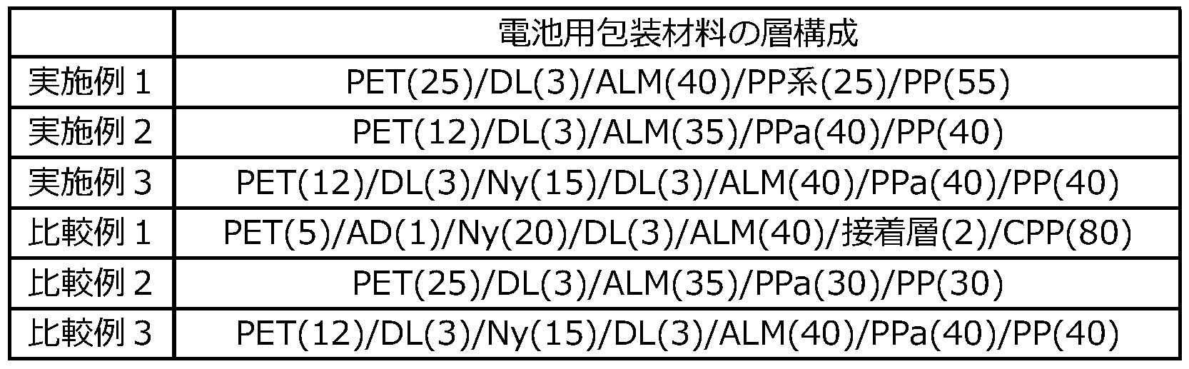
表1において、層構成における括弧内の数値は厚み(μm)を意味する。また、PETはポリエチレンテレフタレート、Nyはナイロン、ADは熱可塑性樹脂層、DLはドライラミネート法により形成された接着剤層、ALMはアルミニウム箔、CPPは無延伸ポリプロピレン(CPP)により形成された熱融着性樹脂層、PPaは無水マレイン酸変性ポリプロピレンにより形成された接着層、PPはポリプロピレンにより形成された熱融着性樹脂層、PP系はポリプロピレン系樹脂により形成された接着層を意味する。
<融解ピーク温度の測定>
実施例及び比較例において、基材層としての各2軸延伸ポリエチレンテレフタレートフィルム層について、それぞれ、示差走査熱量計(DSC、ティー・エイ・インスツルメント製の示差走査熱量計Q200)により、融解ピーク温度を2回測定した。具体的には、JIS K7121:2012(プラスチックの転移温度測定方法(JIS K7121:1987の追補1))の手順にて、示差走査熱量測定(DSC)により、2軸延伸ポリエチレンテレフタレートフィルム層を、0℃で10分間保持した後、10℃/分の昇温速度で0℃から290℃まで昇温させて、1回目の融解ピーク温度P(℃)を測定した後、290℃にて10分間保持した。次に、10℃/分の降温速度で290℃から0℃まで降温させて10分間保持した。さらに、10℃/分の昇温速度で0℃から290℃まで昇温させて2回目の融解ピーク温度Q(℃)を測定した。なお、窒素ガスの流量は50ml/分とした。以上の手順によって、1回目に測定される融解ピーク温度P(℃)と2回目に測定される融解ピーク温度Q(℃)との差(融解ピーク温度P-融解ピーク温度Q)を算出した。なお、小数点以下は四捨五入した。また、ピークが最大のものを融解ピークとした。結果を表2に示す。
実施例及び比較例において、基材層としての各2軸延伸ポリエチレンテレフタレートフィルム層について、それぞれ、示差走査熱量計(DSC、ティー・エイ・インスツルメント製の示差走査熱量計Q200)により、融解ピーク温度を2回測定した。具体的には、JIS K7121:2012(プラスチックの転移温度測定方法(JIS K7121:1987の追補1))の手順にて、示差走査熱量測定(DSC)により、2軸延伸ポリエチレンテレフタレートフィルム層を、0℃で10分間保持した後、10℃/分の昇温速度で0℃から290℃まで昇温させて、1回目の融解ピーク温度P(℃)を測定した後、290℃にて10分間保持した。次に、10℃/分の降温速度で290℃から0℃まで降温させて10分間保持した。さらに、10℃/分の昇温速度で0℃から290℃まで昇温させて2回目の融解ピーク温度Q(℃)を測定した。なお、窒素ガスの流量は50ml/分とした。以上の手順によって、1回目に測定される融解ピーク温度P(℃)と2回目に測定される融解ピーク温度Q(℃)との差(融解ピーク温度P-融解ピーク温度Q)を算出した。なお、小数点以下は四捨五入した。また、ピークが最大のものを融解ピークとした。結果を表2に示す。
実施例1,2及び比較例2の各2軸延伸ポリエチレンテレフタレートフィルム層の融解ピーク温度は、それぞれ、各電池用包装材料の2軸延伸ポリエチレンテレフタレートフィルムとアルミニウム箔との間を、塩酸を用いて剥離し、2軸延伸ポリエチレンテレフタレートフィルム層の表面を十分に水洗、室温乾燥させてから、測定を行った。また、実施例3、比較例1,3の各2軸延伸ポリエチレンテレフタレートフィルム層の融解ピーク温度は、それぞれ、各電池用包装材料の2軸延伸ポリエチレンテレフタレートフィルムと2軸延伸ナイロンフィルムとの間を、塩酸を用いて剥離し、2軸延伸ポリエチレンテレフタレートフィルム層の表面を十分に水洗、室温乾燥させてから、測定を行った。
<2軸延伸ポリエチレンテレフタレートフィルム表面の算術平均粗さRaの測定>
JIS B 0601-2001に規定された方法に準拠し、上記で得られた各電池用包装材料の最表面を構成している2軸延伸ポリエチレンテレフタレートフィルム(ポリエステルフィルム層)のバリア層とは反対側の表面について算術平均粗さRaを測定した。算術平均粗さRaの測定装置としては、Zygo社製の白色干渉計NewView7300を用い、測定面積0.22mm角(対物レンズ50倍、ズームレンズ1倍)、傾き補正あり(Cylinder)の条件で測定を行った。当該算術平均粗さRaは、電池用包装材料の状態で測定した。なお、測定に際して、2軸延伸ポリエチレンテレフタレートフィルムの表面を拭き取るなどの操作は行っていない。結果を表2に示す。
JIS B 0601-2001に規定された方法に準拠し、上記で得られた各電池用包装材料の最表面を構成している2軸延伸ポリエチレンテレフタレートフィルム(ポリエステルフィルム層)のバリア層とは反対側の表面について算術平均粗さRaを測定した。算術平均粗さRaの測定装置としては、Zygo社製の白色干渉計NewView7300を用い、測定面積0.22mm角(対物レンズ50倍、ズームレンズ1倍)、傾き補正あり(Cylinder)の条件で測定を行った。当該算術平均粗さRaは、電池用包装材料の状態で測定した。なお、測定に際して、2軸延伸ポリエチレンテレフタレートフィルムの表面を拭き取るなどの操作は行っていない。結果を表2に示す。
<成形によるカールの評価>
上記で得られた電池用包装材料を裁断して、TD(Transverse Direction)150mm×MD(Machine Direction)90mmの短冊片を作製し、これを試験サンプルとした。31.6mm×54.5mmの矩形状の雄型(表面は、JIS B 0659-1:2002附属書1(参考) 比較用表面粗さ標準片の表2に規定される、最大高さ粗さ(Rzの呼び値)が1.6μmである。コーナーR2.0mm、稜線R1.0mm)とこの雄型とのクリアランスが0.3mmの雌型(表面は、JIS B 0659-1:2002附属書1(参考) 比較用表面粗さ標準片の表2に規定される、最大高さ粗さ(Rzの呼び値)が3.2μmである。コーナーR2.0mm、稜線R1.0mm)からなる金型を用い、雄型側に熱融着性樹脂層側が位置するように雌型上に上記試験サンプルを載置し、31.6mm(MD)×54.5mm(TD)、成形深さ6mmとなるように当該試験サンプルを0.1MPaの押え圧(面圧)で押えて、冷間成形(引き込み1段成形)した。成形を行った位置の詳細は、図8に示される通りである。図8に示されるように、矩形状の成形部Mと電池用包装材料10の端部Pとの最短距離d=70.5mmとなる位置で成形した。成形部Mは、金型によって凹部が形成される位置を示している。次に、成形後の電池用包装材料10を、図9に示すようにして水平面20におき、水平面20から端部Pまでの垂直方向yの距離の最大値tをカールしている部分の最大高さとした。成形によるカールの評価基準は、以下の通りである。結果を表2に示す。
A:t=0mm以上、10mm未満であり、カールが小さい。
B:t=10mm以上、15mm未満であり、カールがやや大きい。
C:t=15mm以上、20mm未満であり、カールが大きい。
D:t=20mm以上であり、カールが非常に大きい。

表2に示される結果から明らかな通り、少なくとも、基材層、バリア層、及び熱融着性樹脂層をこの順に備える積層体から構成されている電池用包装材料において、基材層が、少なくとも、ポリエステルフィルム層を有しており、さらに、示差走査熱量測定により、ポリエステルフィルム層の融解ピーク温度を2回測定した場合に、1回目の昇温において測定される融解ピーク温度P(℃)と2回目の昇温において測定される融解ピーク温度Q(℃)との差が、5℃より大きい実施例1~3においては、電池用包装材料の成形によるカールが好適に抑制されていることが分かる。前記の成形によるカールの評価において、tが10mm以上である場合、生産性が低下する虞がある。
1 基材層
11 ポリエステルフィルム層
11a ポリエステルフィルム層の最外層側の表面(最表面)
12 ポリアミドフィルム層
13 接着剤層
2 接着剤層
3 バリア層
4 熱融着性樹脂層
5 接着層
6 表面被覆層
10 電池用包装材料
11 ポリエステルフィルム層
11a ポリエステルフィルム層の最外層側の表面(最表面)
12 ポリアミドフィルム層
13 接着剤層
2 接着剤層
3 バリア層
4 熱融着性樹脂層
5 接着層
6 表面被覆層
10 電池用包装材料
Claims (6)
- 少なくとも、基材層、バリア層、及び熱融着性樹脂層をこの順に備える積層体から構成されており、
前記基材層は、少なくとも、ポリエステルフィルム層を有しており、
示差走査熱量測定により、前記ポリエステルフィルム層の融解ピーク温度を2回測定した場合に、1回目の昇温において測定される融解ピーク温度P(℃)と2回目の昇温において測定される融解ピーク温度Q(℃)との差が、5℃より大きい、電池用包装材料。 - 前記バリア層と前記熱融着性樹脂層との間に、接着層を備えており、
前記接着層の厚みが、10μm以上である、請求項1に記載の電池用包装材料。 - JIS B 0601-2001に規定された方法に準拠し、前記ポリエステルフィルム層の前記バリア層とは反対側の表面について測定した算術平均粗さRaが、10nm以上である、請求項1または2に記載の電池用包装材料。
- 少なくとも正極、負極、及び電解質を備えた電池素子が、請求項1~3のいずれかに記載の電池用包装材料により形成された包装体中に収容されている、電池。
- 少なくとも、基材層、バリア層、及び熱融着性樹脂層がこの順となるように積層して積層体を得る工程を備えており、
前記基材層として、少なくとも、ポリエステルフィルム層を有しており、かつ、示差走査熱量測定により、前記ポリエステルフィルム層の融解ピーク温度を2回測定した場合に、1回目の昇温において測定される融解ピーク温度P(℃)と、2回目の昇温において測定される融解ピーク温度Q(℃)との差が、5℃より大きいものを用いる、電池用包装材料の製造方法。 - 電池用包装材料の基材層に使用するポリエステルフィルムであって、
示差走査熱量測定により、前記ポリエステルフィルムの融解ピーク温度を2回測定した場合に、1回目の昇温において測定される融解ピーク温度P(℃)と2回目の昇温において測定される融解ピーク温度Q(℃)との差が、5℃より大きい、ポリエステルフィルム。
Priority Applications (3)
| Application Number | Priority Date | Filing Date | Title |
|---|---|---|---|
| CN201980002641.1A CN110710016A (zh) | 2018-04-11 | 2019-04-11 | 电池用包装材料、其制造方法、聚酯膜和电池 |
| JP2019559854A JP6638875B1 (ja) | 2018-04-11 | 2019-04-11 | 電池用包装材料、その製造方法、ポリエステルフィルム、及び電池 |
| CN202311610051.1A CN117613473A (zh) | 2018-04-11 | 2019-04-11 | 电池用包装材料、其制造方法、聚酯膜和电池 |
Applications Claiming Priority (2)
| Application Number | Priority Date | Filing Date | Title |
|---|---|---|---|
| JP2018075968 | 2018-04-11 | ||
| JP2018-075968 | 2018-04-11 |
Publications (1)
| Publication Number | Publication Date |
|---|---|
| WO2019198802A1 true WO2019198802A1 (ja) | 2019-10-17 |
Family
ID=68164208
Family Applications (1)
| Application Number | Title | Priority Date | Filing Date |
|---|---|---|---|
| PCT/JP2019/015869 Ceased WO2019198802A1 (ja) | 2018-04-11 | 2019-04-11 | 電池用包装材料、その製造方法、ポリエステルフィルム、及び電池 |
Country Status (3)
| Country | Link |
|---|---|
| JP (1) | JP6638875B1 (ja) |
| CN (2) | CN110710016A (ja) |
| WO (1) | WO2019198802A1 (ja) |
Families Citing this family (4)
| Publication number | Priority date | Publication date | Assignee | Title |
|---|---|---|---|---|
| WO2021157673A1 (ja) * | 2020-02-05 | 2021-08-12 | 大日本印刷株式会社 | 蓄電デバイス用外装材、その製造方法、及び蓄電デバイス |
| WO2021215538A1 (ja) * | 2020-04-24 | 2021-10-28 | 大日本印刷株式会社 | 蓄電デバイス用外装材、その製造方法、及び蓄電デバイス |
| CN114228094B (zh) * | 2021-12-16 | 2023-08-15 | 云阳金田塑业有限公司 | 一种代替纸质标签的双向拉伸聚丙烯发泡薄膜制备方法 |
| CN114678637B (zh) * | 2022-04-18 | 2023-12-08 | 江苏睿捷新材料科技有限公司 | 一种锂离子电池包装用铝塑复合膜及电池 |
Citations (6)
| Publication number | Priority date | Publication date | Assignee | Title |
|---|---|---|---|---|
| JP2006324055A (ja) * | 2005-05-17 | 2006-11-30 | Toyo Seikan Kaisha Ltd | 角形缶蓋 |
| JP2015131888A (ja) * | 2014-01-10 | 2015-07-23 | 東レ株式会社 | ポリエステルフィルム、該フィルムと金属箔との複合体、複合体にシーラント層を積層した構成体。 |
| JP2015147309A (ja) * | 2014-02-05 | 2015-08-20 | 東レ株式会社 | 二軸配向ポリエステルフィルム |
| JP2017136833A (ja) * | 2016-01-19 | 2017-08-10 | 大日本印刷株式会社 | 積層フィルム |
| WO2017209217A1 (ja) * | 2016-05-31 | 2017-12-07 | 大日本印刷株式会社 | 電池用包装材料、その製造方法、電池、及びポリエステルフィルム |
| WO2018066670A1 (ja) * | 2016-10-05 | 2018-04-12 | 大日本印刷株式会社 | 電池用包装材料、その製造方法、及び電池 |
Family Cites Families (3)
| Publication number | Priority date | Publication date | Assignee | Title |
|---|---|---|---|---|
| JP2004009599A (ja) * | 2002-06-07 | 2004-01-15 | Toray Ind Inc | 金属ラミネート用積層ポリエステルフィルム |
| JP4380728B2 (ja) * | 2007-05-16 | 2009-12-09 | ソニー株式会社 | 積層型包装材料、電池用外装部材および電池 |
| HK1207102A1 (en) * | 2012-07-24 | 2016-01-22 | 尤尼吉可株式会社 | Polyester film for cold forming and method for producing same |
-
2019
- 2019-04-11 CN CN201980002641.1A patent/CN110710016A/zh active Pending
- 2019-04-11 JP JP2019559854A patent/JP6638875B1/ja active Active
- 2019-04-11 CN CN202311610051.1A patent/CN117613473A/zh active Pending
- 2019-04-11 WO PCT/JP2019/015869 patent/WO2019198802A1/ja not_active Ceased
Patent Citations (6)
| Publication number | Priority date | Publication date | Assignee | Title |
|---|---|---|---|---|
| JP2006324055A (ja) * | 2005-05-17 | 2006-11-30 | Toyo Seikan Kaisha Ltd | 角形缶蓋 |
| JP2015131888A (ja) * | 2014-01-10 | 2015-07-23 | 東レ株式会社 | ポリエステルフィルム、該フィルムと金属箔との複合体、複合体にシーラント層を積層した構成体。 |
| JP2015147309A (ja) * | 2014-02-05 | 2015-08-20 | 東レ株式会社 | 二軸配向ポリエステルフィルム |
| JP2017136833A (ja) * | 2016-01-19 | 2017-08-10 | 大日本印刷株式会社 | 積層フィルム |
| WO2017209217A1 (ja) * | 2016-05-31 | 2017-12-07 | 大日本印刷株式会社 | 電池用包装材料、その製造方法、電池、及びポリエステルフィルム |
| WO2018066670A1 (ja) * | 2016-10-05 | 2018-04-12 | 大日本印刷株式会社 | 電池用包装材料、その製造方法、及び電池 |
Also Published As
| Publication number | Publication date |
|---|---|
| CN110710016A (zh) | 2020-01-17 |
| JPWO2019198802A1 (ja) | 2020-04-30 |
| JP6638875B1 (ja) | 2020-01-29 |
| CN117613473A (zh) | 2024-02-27 |
Similar Documents
| Publication | Publication Date | Title |
|---|---|---|
| JP7294495B2 (ja) | 電池用包装材料、その製造方法、及び電池 | |
| JP7238403B2 (ja) | 電池用包装材料、その製造方法、及び電池 | |
| JP6566133B2 (ja) | 電池用包装材料、その製造方法、電池、及びポリエステルフィルム | |
| WO2018097329A1 (ja) | 電池用包装材料、その製造方法、及び電池 | |
| JP6587039B1 (ja) | 電池用包装材料、電池、これらの製造方法、及びポリエステルフィルム | |
| JP7416347B1 (ja) | 蓄電デバイス用外装材、その製造方法、及び蓄電デバイス | |
| JP6638875B1 (ja) | 電池用包装材料、その製造方法、ポリエステルフィルム、及び電池 | |
| JPWO2019070078A1 (ja) | 電池用包装材料及び電池 | |
| JPWO2017188445A1 (ja) | 電池用包装材料及び電池 | |
| WO2019078284A1 (ja) | 電池用包装材料及び電池 | |
| WO2022071547A1 (ja) | 蓄電デバイス用外装材、その製造方法、及び蓄電デバイス | |
| JP7332072B1 (ja) | 蓄電デバイス用外装材、その製造方法、及び蓄電デバイス | |
| WO2023058453A1 (ja) | 蓄電デバイス用外装材、その製造方法、及び蓄電デバイス | |
| JP2017107861A (ja) | 電池用包装材料のシーラント層用の樹脂組成物 | |
| JP6769142B2 (ja) | 電池用包装材料、その製造方法及び電池 | |
| JP7831283B2 (ja) | 蓄電デバイス用外装材、その製造方法、及び蓄電デバイス | |
| JP5761278B2 (ja) | 電池用包装材料のシーラント層用の樹脂組成物 | |
| WO2024214753A1 (ja) | 蓄電デバイス用外装材、その製造方法、及び蓄電デバイス | |
| JP6275080B2 (ja) | 電池用包装材料のシーラント層用の樹脂組成物 |
Legal Events
| Date | Code | Title | Description |
|---|---|---|---|
| ENP | Entry into the national phase |
Ref document number: 2019559854 Country of ref document: JP Kind code of ref document: A |
|
| 121 | Ep: the epo has been informed by wipo that ep was designated in this application |
Ref document number: 19784940 Country of ref document: EP Kind code of ref document: A1 |
|
| NENP | Non-entry into the national phase |
Ref country code: DE |
|
| 122 | Ep: pct application non-entry in european phase |
Ref document number: 19784940 Country of ref document: EP Kind code of ref document: A1 |