WO2019198609A1 - 発泡成形体の製造方法及び製造装置 - Google Patents
発泡成形体の製造方法及び製造装置 Download PDFInfo
- Publication number
- WO2019198609A1 WO2019198609A1 PCT/JP2019/014937 JP2019014937W WO2019198609A1 WO 2019198609 A1 WO2019198609 A1 WO 2019198609A1 JP 2019014937 W JP2019014937 W JP 2019014937W WO 2019198609 A1 WO2019198609 A1 WO 2019198609A1
- Authority
- WO
- WIPO (PCT)
- Prior art keywords
- pressure
- molten resin
- screw
- zone
- measurement
- Prior art date
- Legal status (The legal status is an assumption and is not a legal conclusion. Google has not performed a legal analysis and makes no representation as to the accuracy of the status listed.)
- Ceased
Links
Images


Classifications
-
- B—PERFORMING OPERATIONS; TRANSPORTING
- B29—WORKING OF PLASTICS; WORKING OF SUBSTANCES IN A PLASTIC STATE IN GENERAL
- B29C—SHAPING OR JOINING OF PLASTICS; SHAPING OF MATERIAL IN A PLASTIC STATE, NOT OTHERWISE PROVIDED FOR; AFTER-TREATMENT OF THE SHAPED PRODUCTS, e.g. REPAIRING
- B29C44/00—Shaping by internal pressure generated in the material, e.g. swelling or foaming ; Producing porous or cellular expanded plastics articles
- B29C44/34—Auxiliary operations
- B29C44/36—Feeding the material to be shaped
- B29C44/38—Feeding the material to be shaped into a closed space, i.e. to make articles of definite length
- B29C44/42—Feeding the material to be shaped into a closed space, i.e. to make articles of definite length using pressure difference, e.g. by injection or by vacuum
-
- B—PERFORMING OPERATIONS; TRANSPORTING
- B29—WORKING OF PLASTICS; WORKING OF SUBSTANCES IN A PLASTIC STATE IN GENERAL
- B29C—SHAPING OR JOINING OF PLASTICS; SHAPING OF MATERIAL IN A PLASTIC STATE, NOT OTHERWISE PROVIDED FOR; AFTER-TREATMENT OF THE SHAPED PRODUCTS, e.g. REPAIRING
- B29C44/00—Shaping by internal pressure generated in the material, e.g. swelling or foaming ; Producing porous or cellular expanded plastics articles
- B29C44/34—Auxiliary operations
- B29C44/60—Measuring, controlling or regulating
-
- B—PERFORMING OPERATIONS; TRANSPORTING
- B29—WORKING OF PLASTICS; WORKING OF SUBSTANCES IN A PLASTIC STATE IN GENERAL
- B29C—SHAPING OR JOINING OF PLASTICS; SHAPING OF MATERIAL IN A PLASTIC STATE, NOT OTHERWISE PROVIDED FOR; AFTER-TREATMENT OF THE SHAPED PRODUCTS, e.g. REPAIRING
- B29C45/00—Injection moulding, i.e. forcing the required volume of moulding material through a nozzle into a closed mould; Apparatus therefor
- B29C45/17—Component parts, details or accessories; Auxiliary operations
- B29C45/46—Means for plasticising or homogenising the moulding material or forcing it into the mould
- B29C45/47—Means for plasticising or homogenising the moulding material or forcing it into the mould using screws
- B29C45/50—Axially movable screw
-
- B—PERFORMING OPERATIONS; TRANSPORTING
- B29—WORKING OF PLASTICS; WORKING OF SUBSTANCES IN A PLASTIC STATE IN GENERAL
- B29C—SHAPING OR JOINING OF PLASTICS; SHAPING OF MATERIAL IN A PLASTIC STATE, NOT OTHERWISE PROVIDED FOR; AFTER-TREATMENT OF THE SHAPED PRODUCTS, e.g. REPAIRING
- B29C45/00—Injection moulding, i.e. forcing the required volume of moulding material through a nozzle into a closed mould; Apparatus therefor
- B29C45/17—Component parts, details or accessories; Auxiliary operations
- B29C45/46—Means for plasticising or homogenising the moulding material or forcing it into the mould
- B29C45/58—Details
- B29C45/60—Screws
Definitions
- the present invention relates to a method and apparatus for producing a foamed molded product.
- Patent Documents 1 to 3 an injection foam molding method using nitrogen or carbon dioxide in a supercritical state as a physical foaming agent has been studied and put into practical use.
- the injection foam molding method using a physical foaming agent is performed as follows. First, a physical foaming agent is introduced into a hermetically sealed plasticizing cylinder, and contact dispersed in the plasticized and melted resin. While maintaining the inside of the plasticizing cylinder at a high pressure so that the physical foaming agent is in a supercritical state, the molten resin in which the physical foaming agent is dispersed is weighed and injected into the mold.
- the supercritical fluid that is compatible with the molten resin is rapidly decompressed and gasified during injection filling, and the molten resin is solidified to form bubbles (foamed cells) inside the molded body.
- the physical foaming agent is measured at a pressure slightly higher than the internal pressure of the resin, and is introduced into the plasticizing cylinder after the measurement. Therefore, the amount of the physical foaming agent dissolved in the molten resin is determined by the amount of physical foaming agent introduced (introduction amount control).
- Patent Document 4 discloses a method of introducing a physical foaming agent into a plasticizing cylinder by pressure control instead of introduction amount control in an injection foam molding method using a physical foaming agent.
- a starvation zone in which a molten resin is not filled is provided in a plasticizing cylinder, and a physical foaming agent having a constant pressure is introduced into the starvation zone.
- the starved molten resin is brought into contact with a physical foaming agent at a certain pressure to allow the physical foaming agent to penetrate into the molten resin.
- the starvation zone is always maintained at a constant pressure of the physical blowing agent introduced.
- the injection foam molding method of Patent Document 4 since the physical foaming agent is introduced into the plasticizing cylinder by pressure control, it is not necessary to control the amount of introduction of the physical foaming agent into the molten resin, the introduction time, and the like. Therefore, the injection foam molding method of Patent Document 4 can omit or simplify a complicated control device, and can reduce the device cost. Moreover, the amount of dissolution (penetration amount) of the physical foaming agent into the molten resin can be stabilized by a simple mechanism.
- the present invention solves the above-described problems, and provides a method for stably producing a high-quality foamed molded article by suppressing the separation of the physical foaming agent from the molten resin.
- a method for producing a foamed molded article comprising a screw provided in the interior so as to be freely rotatable and retreatable, and the thermoplastic resin is plasticized and melted to become a molten resin.
- the manufacturing method includes a zone and a starvation zone in which the molten resin is starved, and includes a plasticizing cylinder in which an introduction port for introducing a physical foaming agent is formed in the starvation zone.
- the thermoplastic resin is plasticized and melted to form the molten resin
- the starvation zone has a first pressure that is a constant pressure and includes the physical foaming agent.
- the measured pressure of the molten resin may be maintained at a pressure 0.5 MPa to 10 MPa higher than the first pressure.
- the screw back pressure may always be maintained at a pressure higher than the first pressure. Further, the screw back pressure is maintained at a second pressure higher than the first pressure until the measurement of the molten resin is completed, and the screw back pressure is changed from the completion of the measurement of the molten resin to the start of injection. You may hold
- the screw is provided in the plasticizing cylinder so as to be movable forward and backward from the plasticizing zone toward the starvation zone and backward from the starvation zone to the plasticizing zone, and the screw includes the plasticizing cylinder.
- a tip end seal mechanism that prevents the molten resin from flowing backward from the front to the rear, the tip end seal mechanism including a screw head positioned at a front end of the screw, and a screw head of the screw head.
- Abutting ring located at the rear, a shaft connecting the screw head and the abutting ring, and loosely fitted on the shaft, and can be moved forward and backward between the screw head and the abutting ring. You may have a check ring.
- the ratio (S1 / S2) of the pressure receiving area S1 on the front side of the check ring to the pressure receiving area S2 on the rear side is 0.6 to 0.95. May be.
- a through hole through which the shaft passes is formed in the check ring, and a part of an inner wall defining the through hole of the check ring is formed by a rear end portion of the through hole and an inner diameter of the rear end portion.
- a first tapered surface is formed to connect a small inner diameter portion having a small inner diameter, and the shaft connects a connection portion with the abutting ring and a small diameter portion having a diameter smaller than the diameter of the connection portion. You may have the 2nd taper surface to do.
- the check ring is formed with a through hole through which the shaft passes.
- the through hole has a reduced diameter portion having an inner diameter smaller than an inner diameter at a rear end portion, and the check ring has a through hole.
- the partitioning inner wall has a small inner diameter portion that defines a reduced diameter portion of the through hole, a first tapered surface that connects a rear end portion of the through hole and the small inner diameter portion, and the shaft is You may have a small diameter part which has a diameter smaller than the diameter of the connection part with the said abutment ring, and the 2nd taper surface which connects the said connection part and the said small diameter part.
- the taper ratio of the first taper surface and the taper ratio of the second taper surface are substantially the same.
- the first taper surface and the second taper surface are It may be separated and abutted.
- a groove may be formed on the outer surface of the check ring, and the groove may form a labyrinth structure on the outer surface of the check ring.
- the screw can perform forward rotation for sending the molten resin forward and reverse rotation opposite to normal rotation, and the tip end seal mechanism can reversely rotate the screw.
- the check ring has a lock mechanism that maintains a state in which the check ring is in contact with the abutting ring
- the method for manufacturing the foamed molded product includes the reverse rotation of the screw after completion of the measurement of the molten resin, The state where the check ring is in contact with the abutting ring may be maintained.
- a manufacturing apparatus for manufacturing a foam-molded body including a screw provided therein so as to be freely rotatable and retreatable, and the thermoplastic resin is plasticized and melted to become a molten resin.
- a plasticization zone, and a starvation zone in which the molten resin is starved, and an introduction port for introducing a physical foaming agent into the starvation zone is formed.
- a plasticizing cylinder to be injected a physical foaming agent supply mechanism for supplying a physical foaming agent having a first pressure that is a constant pressure to the plasticizing cylinder, and from the completion of the measurement of the molten resin to the start of injection, There is provided a manufacturing apparatus having a pressure holding mechanism for holding a pressure of the measured molten resin at a pressure higher than the first pressure.
- the pressure holding mechanism may be a mechanism for holding the measured pressure of the molten resin at a pressure higher by 0.5 MPa to 10 MPa than the first pressure from the completion of the measurement of the molten resin to the start of injection.
- the pressure holding mechanism may be a screw driving mechanism that controls screw back pressure.
- the screw is provided in the plasticizing cylinder so as to be movable forward and backward from the plasticizing zone toward the starvation zone and backward from the starvation zone to the plasticizing zone.
- a tip end seal mechanism that suppresses backflow of the molten resin from the front to the rear may be provided, and the pressure holding mechanism may be the tip end seal mechanism.
- the screw is capable of forward rotation for sending the molten resin forward and reverse rotation opposite to the forward rotation
- the tip seal mechanism has an end portion at the front of the screw.
- a screw head located at the rear of the screw head, an abutting ring located behind the screw head, a shaft connecting the screw head and the abutting ring, and loosely fitting on the shaft, the screw head and the abutting
- a check ring that can move forward and backward between the rings and a lock mechanism that maintains the state in which the check ring is in contact with the abutment ring by rotating the screw in the reverse direction.
- the method for producing a foam molded article of the present invention provides a production method for stably producing a high quality foam molded article by suppressing separation of the physical foaming agent from the molten resin.
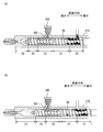
- FIG. 3A is a diagram illustrating a state in the middle of the measurement of the molten resin in the first embodiment
- FIG. 3B is a diagram illustrating a state when the measurement of the molten resin is completed.
- FIG. 4A is a diagram showing the pressure detected by the pressure sensor (load cell) of the screw driving mechanism and the pressure in the starvation zone when the screw back pressure is applied after completion of the measurement of the molten resin in the first embodiment.
- FIG. 4A is a diagram showing the pressure detected by the pressure sensor (load cell) of the screw driving mechanism and the pressure in the starvation zone when the screw back pressure is applied after completion of the measurement of the molten resin in the first embodiment.
- FIG. 4B is a diagram showing the pressure detected by the pressure sensor (load cell) and the pressure in the starvation zone when the screw back pressure is not applied after completion of the measurement of the molten resin.
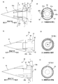
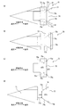
- FIG. 5A is a view showing a state in which the check ring is located in the foremost part in the tip seal mechanism used in the second embodiment
- FIG. 5B is a view showing that the main ring of the check ring is a screw. It is a figure which shows the state which is not contacting both the head and the abutting ring
- FIG.5 (c) is a figure which shows the state in which the check ring was located in the backmost part.
- 5D is a cross-sectional view taken along the line DD ′ in FIG. 5A, and FIG.
- FIG. 5E is a cross-sectional view taken along the line EE ′ in FIG.
- FIG. 5F is a cross-sectional view taken along the line FF ′ in FIG. 6A is a cross-sectional view taken along the line DD ′ of the tip seal mechanism used in the second embodiment shown in FIG. 5A
- FIG. 6B is a tip of another example. It is sectional drawing of a part seal mechanism.
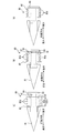
- FIG. 7A is a view showing a state in which the check ring is positioned most forward in the tip seal mechanism used in Modification 1 of the second embodiment, and FIG. It is a figure which shows the state located back.
- FIG. 7C is a view showing only the check ring, and FIG.
- FIG. 7D is a view showing the components (screw head, shaft and abutment ring) of the tip seal mechanism other than the check ring.
- FIG. 8A is a view showing a state in which the check ring is located in the foremost part in the tip end seal mechanism used in Modification 2 of the second embodiment
- FIG. 8B is a view showing the main body of the check ring.
- FIG. 8C is a diagram showing a state where the ring is not in contact with both the screw head and the abutment ring
- FIG. 8C is a diagram showing a state where the check ring is located most rearward.
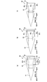
- FIG. 9A is a view showing a state in which the check ring is located in the foremost part in the tip seal mechanism used in Modification 3 of the second embodiment
- FIG. 9B shows the main body of the check ring
- FIG. 9C is a diagram showing a state where the ring is not in contact with both the screw head and the abutting ring
- FIG. 9C is a diagram showing a state where the check ring is located most rearward.
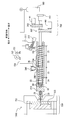
- the manufacturing method of the foaming molding of this embodiment is demonstrated referring the flowchart shown in FIG.
- the manufacturing method of the foaming molding of this embodiment can be implemented using the manufacturing apparatus 1000 shown in FIG. 2, for example. First, the manufacturing apparatus 1000 will be described.
- the manufacturing apparatus (injection molding machine) 1000 mainly includes a plasticizing cylinder 210 in which the screw 20 is installed, a screw driving mechanism 260 that drives the screw 20, and physical foaming that supplies a physical foaming agent to the plasticizing cylinder 210.
- the plasticizing cylinder 210 of the present embodiment the right hand in FIG. 2 is defined as “upstream” or “rear”, and the left hand is defined as “downstream” or “front”.
- the direction in which the plasticizing cylinder 210 and the screw 20 extend is defined as the “front-rear direction”.
- the plasticizing cylinder 210 of the present embodiment when the screw 20 is rotated counterclockwise when viewed from the rear side of the plasticizing cylinder 210 as in the configuration of the conventionally known plasticizing cylinder, the molten resin is removed. It is configured to perform forward rotation sent forward and reverse rotation when rotated clockwise.
- the plasticizing cylinder 210 has a plasticizing zone 21 in which a thermoplastic resin is plasticized and melted to become a molten resin, and a starvation zone 23 in which the molten resin is starved in the downstream side of the plasticizing zone 21.
- the “starvation state” is a state in which the molten resin does not fill the starvation zone 23 but becomes full. Accordingly, a space other than the portion occupied by the molten resin exists in the starvation zone 23.
- An introduction port 202 for introducing a physical foaming agent is formed in the starvation zone 23, and an introduction speed adjusting container 300 is connected to the introduction port 202.
- the cylinder 100 supplies a physical foaming agent to the plasticizing cylinder 210 via the introduction speed adjusting container 300.
- the screw drive mechanism 260 is connected to the rear end portion on the upstream side of the plasticizing cylinder 210, and includes a screw rotation drive mechanism including a screw rotation motor M2 and transmission means 262, a screw forward / rearward movement motor M1 and transmission means 263.
- a screw moving mechanism and a pressure sensor 261 such as a load cell for detecting the pressure applied to the screw 20 are provided.
- the screw rotation motor M2 rotates the screw 20 forward and backward via transmission means 262 composed of pulleys, belts and the like.
- the screw forward / reverse motor M1 moves the screw 20 in the front-rear direction via a transmission means 263 that converts the rotational motion of a pulley, belt, ball screw / nut mechanism, etc. into linear motion. Thereby, the screw 20 can move forward from the plasticization zone 21 toward the hunger zone 23 and move backward from the hunger zone 23 toward the plasticization zone 21.
- the magnitude of the pressure applied to the screw 20 detected by the pressure sensor 261 is the magnitude of the pressure of the molten resin located in front of the screw 20, but when a screw back pressure is applied to the screw 20, It is also the size of the screw back pressure.
- the “screw back pressure” is a force that pushes the screw 20 from the rear to the front. For example, when plasticizing and metering the resin, that is, when the screw 20 rotates forward, the molten resin is sent to the front of the plasticizing cylinder 210, and when the screw 20 moves backward due to the resin pressure, Apply a force (screw back pressure) to push from the back to the front. At this time, the screw back pressure is equal to the pressure of the molten resin located in front of the screw 20.
- the pressure detected by the pressure sensor 26 is not only the pressure of the molten resin located in front of the screw 20 but also the screw back pressure. In the present embodiment, the screw back pressure is controlled by the screw drive mechanism 260.
- the pressure sensor 261 detects only the pressure of the molten resin located in front of the screw 20.
- the pressure detected by the pressure sensor 261 is the pressure of the measured molten resin located in front of the screw 20. is there.
- the screw 20 has a tip end seal mechanism 50 including a check ring 52 at the front end thereof.
- the tip seal mechanism 50 prevents the compressed resin in front of the screw 20 from flowing backward to the rear side.
- the manufacturing apparatus 1000 has only one starvation zone 23, the manufacturing apparatus used for this embodiment is not limited to this.
- the starvation zone 23 and a plurality of introduction ports 202 formed therein are provided, and the physical foaming agent is introduced into the plasticizing cylinder 210 from the plurality of introduction ports 202. It may be a structure.
- thermoplastic resin plasticized and melted to obtain a molten resin (step S1 in FIG. 1).
- thermoplastic resin various resins can be used depending on the type of the target molded article.
- Thermoplastic resins such as imide, polylactic acid, polycaprolactone, and composite materials thereof can be used. These thermoplastic resins may be used alone or in combination of two or more.
- thermoplastic resins those obtained by kneading these thermoplastic resins with various inorganic fillers such as glass fiber, talc, and carbon fiber can be used.
- the thermoplastic resin is preferably mixed with an inorganic filler that functions as a foam nucleating agent and an additive that increases the melt tension. By mixing these, the foamed cell can be miniaturized.
- the thermoplastic resin of this embodiment may contain other general-purpose various additives as necessary.
- the thermoplastic resin of the present embodiment may include a general-purpose chemical foaming agent. The foaming performance can be complemented by adding a small amount of chemical foaming agent.
- thermoplastic resin is plasticized and melted in the plasticizing cylinder 210 in which the screw 20 shown in FIG. 2 is installed.
- a band heater (not shown) is disposed on the outer wall surface of the plasticizing cylinder 210, whereby the plasticizing cylinder 210 is heated, and shear heat generated by the rotation of the screw 20 is further applied to plasticize the thermoplastic resin. Melted.
- ⁇ Pressurized fluid is used as the physical foaming agent.
- “fluid” means any of liquid, gas, and supercritical fluid.
- the physical foaming agent is preferably carbon dioxide, nitrogen or the like from the viewpoint of cost and environmental load. Since the pressure of the physical foaming agent of the present embodiment is relatively low, for example, a fluid extracted from a cylinder in which a fluid such as a nitrogen cylinder, a carbon dioxide cylinder, or an air cylinder is decompressed to a constant pressure by a pressure reducing valve. Can be used. In this case, since the booster is not necessary, the cost of the entire manufacturing apparatus can be reduced. Further, if necessary, a fluid whose pressure has been increased to a predetermined pressure may be used as the physical foaming agent.
- the physical foaming agent is supplied from the introduction port 202 to the starvation zone 23 through the introduction rate adjusting container 300 from the cylinder 100.
- the physical foaming agent is reduced to a predetermined pressure using the pressure reducing valve 151 and then introduced into the starvation zone 23 from the inlet 202 without passing through a pressure raising device or the like.
- the introduction amount, introduction time, etc. of the physical foaming agent introduced into the plasticizing cylinder 210 are not controlled. Therefore, a mechanism for controlling them, for example, a drive valve using a check valve, a solenoid valve, or the like is not necessary in the section from the pressure reducing valve 151 to the introduction port 202.
- the inner diameter of the introduction port 202 is preferably 20% to 100% of the inner diameter of the plasticizing cylinder 210, and more preferably 30% to 80%.
- the inner diameter of the introduction port 202 is preferably 3 mm to 100 mm, and more preferably 5 mm to 50 mm.
- the inner diameter of the introduction port 202 means the inner diameter of the opening on the inner wall of the plasticizing cylinder 210.
- the introduction speed adjustment container 300 connected to the introduction port 202 has a certain volume or more, so that the flow rate of the physical foaming agent introduced into the plasticizing cylinder 210 is slowed, and the physical foaming agent is contained in the introduction speed adjustment container 300. Time to stay can be secured. By staying in the vicinity of the heated plasticizing cylinder 210, the physical foaming agent is heated, the temperature difference between the physical foaming agent and the molten resin is reduced, and the dissolved amount of the physical foaming agent in the molten resin (penetration amount). ) Can be stabilized. That is, the introduction speed adjusting container 300 functions as a buffer container. On the other hand, if the volume of the introduction speed adjusting container 300 is too large, the cost of the entire apparatus increases.
- the pressure of the measured molten resin is 0.5 MPa from the constant pressure (the first pressure) in the starvation zone 23. It is preferably ⁇ 10 MPa higher, more preferably 1 MPa to 10 MPa higher, and even more preferably 2 MPa to 5 MPa higher.
- the screw back pressure (third pressure) from the completion of measurement of the molten resin to the start of injection is preferably equal to or higher than the screw back pressure (second pressure) until the completion of measurement of the molten resin. That is, the third pressure may be the same as the second pressure or higher than the second pressure. As described above, if the screw back pressure (second pressure) until the completion of the measurement of the molten resin is too high, the molten resin cannot be sent to the front of the tip seal mechanism 50, and the molten resin is introduced from the inlet 203 of the starvation zone 23. May vent up.
- the pressure in the metering zone 25 is higher than the constant pressure in the starvation zone 23.
- the pressure in the plasticizing cylinder 210 is not the same pressure. For this reason, when a reverse flow of the molten resin in the measurement zone 25 occurs, the pressure in the measurement zone 25 decreases even if the reverse flow rate is an amount that does not cause a problem in the conventional molding method.
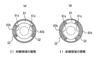
- the pressure receiving area S2 is an area of the end face 62c on the rear side of the main body ring 62a in the state shown in FIG.
- the pressure receiving area S ⁇ b> 2 is an area of a surface (pressure receiving surface) that receives pressure behind the tip seal mechanism 60.
- the pressure receiving area S1 is usually smaller than the pressure receiving area S2 (S1 ⁇ S2).
- the pressure receiving area S3 on the rear side of the check ring 62 is indicated by a hatched area in FIG.
- the pressure receiving area S3 is smaller than the pressure receiving area S2.
- the pressure receiving area S1 is large, that is, if the ratio (S1 / S2) is large, it is difficult to push the check ring 62 back. Since it becomes difficult to send the molten resin forward, the plasticizing ability is lowered, and there is a possibility that the measurement time of the molten resin becomes long. Moreover, the starvation state of the molten resin in the starvation zone 23 may become unstable, and foaming performance may be reduced.
- the pressure receiving areas S1 to S3 shown as hatched regions in FIGS. 5 (d) to 5 (f) and FIGS. 6 (a) and 6 (b) are the areas of the pressure receiving surfaces perpendicular to the front-rear direction. It is.
- the pressure receiving surface is not limited to a plane perpendicular to the front-rear direction.
- the pressure receiving surface may be a flat surface (slope) having an inclination with respect to the front-rear direction, or may be a tapered surface.
- a tip seal mechanism 70 having a tapered contact surface as shown in FIGS. 7A to 7D is used instead of the tip seal mechanism 60 of the second embodiment.
- a foamed molded article is manufactured by the same manufacturing method using the same manufacturing apparatus as in the second embodiment except that the tip seal mechanism 70 is used.
- the tip seal mechanism 70 has the ratio (S1 / S2) within the specific range described above, as with the tip seal mechanism 60 used in the second embodiment.
- FIG. 7A shows a state in which the check ring 72 is located in the foremost position in the tip seal mechanism 70.
- FIG. 7B shows a state in which the check ring 72 is located most rearward.
- FIG. 7C shows only the check ring 72.
- FIG. 7 (d) shows the components of the tip seal mechanism 70 other than the check ring 72, that is, the screw head 71, the shaft 74, and the butting ring 73.
- the check ring 72 has a through hole 75 through which the shaft 74 passes.
- a part of the inner wall that defines the through hole 75 has a first tapered surface 75c that connects the rear end 75a of the through hole 75 and a small inner diameter part 75b having an inner diameter d75 smaller than the inner diameter D75 of the rear end 75a.
- the through hole 75 has a reduced diameter portion having an inner diameter d75 smaller than the inner diameter D75 at the rear end portion 75a.
- the inner wall that divides the through hole 75 of the check ring 72 connects the small inner diameter portion 75b that defines the reduced diameter portion of the through hole 75, the rear end portion 75a of the through hole 75, and the small inner diameter portion 75b. Taper surface 75c.
- the shaft 74 connects the small diameter portion 74b having a diameter d74 smaller than the diameter D74 of the connection portion 74a to the butting ring 73, and the connection portion 74a and the small diameter portion 74b.
- a second tapered surface 74c is provided.
- the taper ratio of the first taper surface 75c and the taper ratio of the second taper surface 74c are substantially the same. As the check ring 72 moves forward and backward, the first tapered surface 75c and the second tapered surface 74c are separated from and abut on each other. As shown in FIG.
- the gap G1 which is the passage path of the molten resin, disappears by the contact between the first tapered surface 75c and the second tapered surface 74c, and the molten resin flows backward. Suppress. Compared with the case where flat surfaces are brought into contact with each other, the contact area between the tapered surfaces is increased. Thereby, in the front-end
- Modification 2 uses a tip seal mechanism 80 having a check ring 82 having a groove 82d formed on the outer surface as shown in FIGS. 8 (a) to 8 (c).
- FIG. 8A shows a state where the check ring 82 is located at the foremost position.
- FIG. 8C shows a state in which the check ring 82 is located most rearward.
- FIG. 8B shows a state in which the main body ring 82a of the check ring 82 is not in contact with both the screw head 81 and the abutting ring 83, that is, an intermediate state between FIGS. 8A and 8C. .
- a foamed molded body is manufactured by the same manufacturing method using the same manufacturing apparatus as in the second embodiment except that the tip seal mechanism 80 is used.
- the tip seal mechanism 80 has a ratio (S1 / S2) value within the specific range described above, similarly to the tip seal mechanism 60 used in the second embodiment.
- the number of the grooves 82d is large, and the groove 82d forms a labyrinth structure on the outer surface of the check ring 82. It is preferable. For this reason, the length L82a in the front-rear direction of the main body ring 82a is preferably longer. On the other hand, when the length L82a of the main body ring 82a is long, the movement distance in the front-rear direction of the check ring 82 is long, and the time during which the gap G1 formed between the shaft 84 and the check ring 82 is open is long. Become.
- the contact surface between the shaft 94 and the check ring 92 is a tapered surface.
- the gap G1 that is the passage path of the molten resin is eliminated by the contact between the first tapered surface 95c and the second tapered surface 94c, Suppresses backflow.
- a foamed molded article is manufactured by the same manufacturing method using the same manufacturing apparatus as in the second embodiment except that the tip seal mechanism 90 is used. Further, the tip seal mechanism 90 has the ratio (S1 / S2) within the specific range described above, as with the tip seal mechanism 60 used in the second embodiment.
- Modification 3 has the same effects as those of the second embodiment described above. Further, the tip end seal mechanism 90 of the present modification forms a groove 92d on the outer surface of the check ring 92, thereby enhancing the seal between the outer surface of the check ring 92 and the inner wall of the plasticizing cylinder 210. By making the contact surface of 94 and the check ring 92 a tapered surface, the sealing performance of the gap G1 can be enhanced.
- the lock mechanism of the tip seal mechanism is arbitrary as long as the check ring is kept in contact with the abutting ring by the reverse rotation of the screw.
- Japanese Patent No. 3432776 Japanese Patent No. 5019165 It is possible to use a mechanism disclosed in Japanese Patent Publication No.
- a manufacturing apparatus having the same structure as that of the manufacturing apparatus 1000 used in the first embodiment shown in FIG. 2 is used except that a tip seal mechanism having a lock mechanism is provided.
- the foam molded body is manufactured by the same method as in the first embodiment except that the screw 20 is reversely rotated after the measurement of the molten resin is completed. .
- the screw 20 is reversely rotated after the measurement of the molten resin is completed.
- the pressure can be maintained higher than a constant pressure of 23. Thereby, it can suppress that a physical foaming agent isolate
- the manufacturing apparatus 1000 shown in FIG. 2 provided with the tip seal mechanism 60 shown in FIGS. 5 (a) to 5 (e) was used. Details of the manufacturing apparatus 1000 will be described.
- the manufacturing apparatus (injection molding machine) 1000 mainly includes a plasticizing cylinder 210 in which the screw 20 is installed, a screw driving mechanism 260 for driving the screw 20, and a physical foaming agent in the plasticizing cylinder 210.
- a cylinder 100 which is a physical foaming agent supply mechanism to be supplied to a mold, a mold clamping unit 250 provided with a mold 251, a control device for controlling the operation of the plasticizing cylinder 210, screw drive mechanism 260 and mold clamping unit 250 ( (Not shown).
- the nozzle tip 29 of the plasticizing cylinder 210 is provided with a shut-off valve 28 that opens and closes by driving the air cylinder, so that the inside of the plasticizing cylinder 210 can be held at a high pressure.
- a mold 251 is in close contact with the nozzle tip 29, and molten resin is injected and filled from the nozzle tip 29 into a cavity 253 formed by the mold 251.
- On the upper side surface of the plasticizing cylinder 210 in order from the upstream side, a resin supply port 201 for supplying a thermoplastic resin to the plasticizing cylinder 210 and an introduction port 202 for introducing a physical foaming agent into the plasticizing cylinder 210. Is formed.
- the resin supply port 201 and the introduction port 202 are provided with a resin supply hopper 211, a feeder screw 212, and an introduction speed adjusting container 300, respectively.
- the cylinder 100 is connected to the introduction speed adjusting container 300 by a pipe 154 through a pressure reducing valve 151 and a pressure gauge 152. Further, a sensor (not shown) for monitoring the pressure in the starvation zone 23 is provided in the starvation zone 23 of the plasticizing cylinder 210.
- the plasticizing cylinder 210 in order from the upstream side, the plasticizing zone 21 in which the thermoplastic resin is plasticized and melted, the compression zone 22 in which the molten resin is compressed and the pressure is increased, and the starvation in which the molten resin is unfilled A recompression zone 24 is formed in which the molten resin decompressed in the zone 23 and the starvation zone is compressed again.
- the inner diameter of the plasticizing cylinder 210 was 35 mm, and the inner diameter of the introduction port 202 was 8 mm. Therefore, the inner diameter of the introduction port 202 was about 23% of the inner diameter of the plasticizing cylinder 210.
- the volume of the introduction speed adjusting container 300 was about 80 mL.
- the ratio (S1 / S2) of the pressure receiving area S1 on the front side of the check ring 62 to the pressure receiving area S2 on the rear side was 0.75.
- a mold 251 having a size of the cavity 253 of 100 mm ⁇ 200 mm ⁇ 3 mm is used.
- the plasticizing zone 21 was adjusted to 210 ° C, the compression zone 22 to 200 ° C, the starvation zone 23 to 200 ° C, and the recompression zone 24 to 210 ° C by a band heater (not shown). Then, while the feeder screw 212 was rotated at a rotation speed of 30 rpm from the resin supply hopper 211, resin pellets of thermoplastic resin were supplied to the plasticizing cylinder 210, and the screw 20 was rotated forward. Thereby, in the plasticization zone 21, the thermoplastic resin was heated and kneaded to obtain a molten resin.
- the number of rotations of the feeder screw 212 was determined in advance by setting (conditioning) the molding conditions of the present example by molding a solid molded body (non-foamed molded body) and starving and feeding the resin pellets.
- the starvation supply of resin pellets means that in the plasticizing zone 21, during the supply of resin pellets, a state in which the resin pellets or molten resin thereof is not filled in the plasticizing cylinder is maintained, and the supplied resin pellets or molten resin is supplied. Means that the flight of the screw 20 is exposed.
- the confirmation of the starvation supply of resin pellets includes, for example, a method of confirming the presence or absence of resin pellets or molten resin on the screw 20 with an infrared sensor or a visualization camera.
- the feeder screw 212 used was provided with a transparent window, and the state of the plasticizing zone 21 immediately below the resin supply port 201 was visually confirmed through the transparent window.
- the molten resin was caused to flow from the plasticization zone 21 to the compression zone 22 and further to the starvation zone 23 by rotating the screw 20 forward at a screw back pressure of 9 MPa and a rotation speed of 100 rpm.
- the amount of the molten resin supplied to the starvation zone 23 was limited. As a result, the molten resin was compressed in the compression zone 22 and the pressure increased, and the molten resin became unfilled (starved state) in the starvation zone 23 on the downstream side.
- the physical foaming agent (nitrogen) introduced from the introduction port 202 exists in the space where the molten resin does not exist, and the molten resin is caused by the physical foaming agent. Pressurized.
- the molten resin is sent to the recompression zone 24 and recompressed, the screw 20 moves backward and stops at a predetermined position (measuring completion position), and one shot of the molten resin is placed at the tip of the plasticizing cylinder 210. Weighed. The metering time was 10 seconds. After completion of the measurement, the screw back pressure was increased from 9 MPa to 10 MPa. As a result, the screw 20 moved forward by 0.3 mm to 0.4 mm from the measurement completion position.
- the shut-off valve 28 was opened, and molten resin was injected and filled into the cavity 253 so as to have a filling rate of 90% of the volume of the cavity, thereby forming a flat foam-shaped molded body (short shot method).
- the screw back pressure is applied after the completion of the measurement of the molten resin, the screw position at the start of injection deviates from the measurement completion position. Since the amount of deviation differs from shot to shot, the injection amount was controlled based on the stroke (movement amount) of the screw 20 rather than the position of the screw 20 before and after injection.
- the foamed molded product was taken out of the mold after waiting for the foamed molded product to cool. The cooling time was 10 seconds.
- the molding cycle was 23 seconds, which was equivalent to the molding cycle of the solid molded body (non-foamed molded body).
- Example 2 a foamed molded article was produced by the same method using the same production apparatus as in Example 1 except that the screw back pressure was not applied after completion of the measurement of the molten resin.
- the screw back pressure was set to 9 MPa until the measurement of the molten resin was completed, and 0 (zero) after the measurement of the molten resin was completed.
- the resin pressure in front of the screw 20 detected by the pressure sensor 261 (load cell) of the screw driving mechanism 260 is reduced from 9 MPa to 2 MPa to 7 MPa. The difference was 1 MPa.
- molten resin was injected into the mold to obtain a foamed molded product.
- the measurement time of the molten resin was the same as in Example 1.
- the injection molding of the molded body described above was continuously performed for 100 shots to obtain 100 foam molded bodies. Similar to Example 1, during the production of 100 foamed molded articles, the pressure in the starvation zone 23 was always constant at 6 MPa.
- the foam cell of the cross section of the obtained foam molded product was observed.
- the average cell diameter of the foamed cells was 30-40 ⁇ m, which was larger than Example 1 but fine. No enlargement or non-uniformity of the foam cell diameter was confirmed.
- Example 3 In the present embodiment, in the tip seal mechanism 60, as shown in FIG. 6B, by increasing the front end face of the claw 62b of the check ring 62, S1 is increased, and the ratio (S1 / S2) was set to 0.9. Further, no screw back pressure was applied after completion of the measurement of the molten resin. Except for this, a foamed molded article was produced in the same manner using the same production apparatus as in Example 1.
- the screw back pressure was set to 9 MPa until the measurement of the molten resin was completed, and 0 (zero) after the measurement of the molten resin was completed.
- the resin pressure in front of the screw 20 detected by the pressure sensor 261 (load cell) of the screw drive mechanism 260 was 8.5 MPa, and the reduction was only 0.5 MPa.
- the ratio (S1 / S2) of the present embodiment is larger than that of the first embodiment, it is difficult to send the molten resin to the front of the front end seal mechanism 60 and the plasticizing ability is low.
- the measurement time of the molten resin was as long as 1.5 times the measurement time of Example 1.
- the injection molding of the molded body described above was continuously performed for 100 shots to obtain 100 foam molded bodies. Similar to Example 1, during the production of 100 foamed molded articles, the pressure in the starvation zone 23 was always constant at 6 MPa.
- the foam cell of the cross section of the obtained foam molded product was observed.
- the average cell diameter of the foamed cells was 20 to 30 ⁇ m, which was the same as in Example 1 and was fine. No enlargement or non-uniformity of the foam cell diameter was confirmed.
- Example 4 In this example, a manufacturing apparatus similar to that of Example 1 was used except that the tip end seal mechanism 90 shown in FIGS. 9A to 9C was provided. In the tip seal mechanism 90, the contact surface between the shaft 94 and the check ring 92 is tapered surfaces 95c and 94c, and a groove 92d is formed on the outer surface of the check ring 92. Further, no screw back pressure was applied after completion of the measurement of the molten resin. Except for this, a foamed molded article was produced in the same manner as in Example 1.
- the screw back pressure was set to 9 MPa until the measurement of the molten resin was completed, and 0 (zero) after the measurement of the molten resin was completed. From the completion of metering to the start of injection, the resin pressure in front of the screw 20 detected by the pressure sensor 261 (load cell) of the screw drive mechanism 260 was 8.6 MPa, and the reduction was only 0.4 MPa.
- the measurement time of the molten resin was the same as in Example 1.
- the injection molding of the molded body described above was continuously performed for 100 shots to obtain 100 foam molded bodies. Similar to Example 1, during the production of 100 foamed molded articles, the pressure in the starvation zone 23 was always constant at 6 MPa.
- the foam cell of the cross section of the obtained foam molded product was observed.
- the average cell diameter of the foamed cells was 20 to 30 ⁇ m, which was the same as in Example 1 and was fine. No enlargement or non-uniformity of the foam cell diameter was confirmed.
- the tip end seal mechanism has a known lock mechanism disclosed in Japanese Patent No. 3432276 that maintains the state in which the check ring is in contact with the abutment ring by rotating the screw in the reverse direction. Used the same manufacturing apparatus as in Example 1. Moreover, after completion of the measurement of the molten resin, the screw back pressure was not applied, and instead, the screw 20 was reversely rotated. Except for this, a foamed molded article was produced in the same manner as in Example 1.
- Example 2 the screw back pressure was set to 9 MPa until the measurement of the molten resin was completed, and 0 (zero) after the measurement of the molten resin was completed. And the screw 20 was reversely rotated 180 degrees, and the state where the check ring contacted the butting ring was maintained. From the completion of measurement to the start of injection, the resin pressure in front of the screw 20 detected by the pressure sensor 261 (load cell) of the screw drive mechanism 260 remained 9.0 MPa and did not decrease. The measurement time of the molten resin was the same as in Example 1.
- the injection molding of the molded body described above was continuously performed for 100 shots to obtain 100 foam molded bodies. Similar to Example 1, during the production of 100 foamed molded articles, the pressure in the starvation zone 23 was always constant at 6 MPa.
- the foam cell of the cross section of the obtained foam molded product was observed.
- the average cell diameter of the foamed cells was 20 to 30 ⁇ m, which was the same as in Example 1 and was fine. No enlargement or non-uniformity of the foam cell diameter was confirmed.
- Example 2 the screw back pressure was set to 9 MPa until the measurement of the molten resin was completed, and 0 (zero) after the measurement of the molten resin was completed.
- the resin pressure in front of the screw 20 detected by the pressure sensor 261 (load cell) of the screw driving mechanism 260 was 6.0 MPa, and the pressure decreased to the pressure in the starvation zone 23.
- the measurement time of the molten resin was the same as in Example 1.
- the injection molding of the molded body described above was continuously performed for 100 shots to obtain 100 foam molded bodies. Similar to Example 1, during the production of 100 foamed molded articles, the pressure in the starvation zone 23 was always constant at 6 MPa.
- the foam cell of the cross section of the obtained foam molded product was observed.
- the average cell diameter of the foamed cells was 50 to 100 ⁇ m, and it was confirmed that the foamed cell diameter was enlarged as compared with Example 1.
- Example 2 the plasticization of the thermoplastic resin and the measurement of the molten resin were performed while applying a screw back pressure of 9 MPa.
- this comparative example has a large ratio (S1 / S2), it is difficult to send the molten resin to the front of the tip seal mechanism 60, and the plasticizing ability is low. It took a very long time to weigh the molten resin. For this reason, it was judged that it was impossible to weigh a predetermined amount of the molten resin while applying a screw back pressure of 9 MPa, and the production of the molded body was stopped during the measurement of the molten resin.
- the manufacturing method of the present invention can simplify the device mechanism related to the physical foaming agent.
- a foamed molded article having excellent foamability can be produced efficiently at low cost.
- the manufacturing method of the foaming molding of this invention can suppress isolation
Landscapes
- Engineering & Computer Science (AREA)
- Manufacturing & Machinery (AREA)
- Mechanical Engineering (AREA)
- Injection Moulding Of Plastics Or The Like (AREA)
- Molding Of Porous Articles (AREA)
Applications Claiming Priority (2)
| Application Number | Priority Date | Filing Date | Title |
|---|---|---|---|
| JP2018-074880 | 2018-04-09 | ||
| JP2018074880A JP7128015B2 (ja) | 2018-04-09 | 2018-04-09 | 発泡成形体の製造方法及び製造装置 |
Publications (1)
| Publication Number | Publication Date |
|---|---|
| WO2019198609A1 true WO2019198609A1 (ja) | 2019-10-17 |
Family
ID=68164078
Family Applications (1)
| Application Number | Title | Priority Date | Filing Date |
|---|---|---|---|
| PCT/JP2019/014937 Ceased WO2019198609A1 (ja) | 2018-04-09 | 2019-04-04 | 発泡成形体の製造方法及び製造装置 |
Country Status (2)
| Country | Link |
|---|---|
| JP (1) | JP7128015B2 (enExample) |
| WO (1) | WO2019198609A1 (enExample) |
Citations (10)
| Publication number | Priority date | Publication date | Assignee | Title |
|---|---|---|---|---|
| JPH079516A (ja) * | 1993-06-29 | 1995-01-13 | Japan Steel Works Ltd:The | 逆流防止機構 |
| JPH0735018U (ja) * | 1993-12-17 | 1995-06-27 | 株式会社名機製作所 | 射出成形機の逆流防止装置 |
| JPH08281734A (ja) * | 1995-04-11 | 1996-10-29 | Japan Steel Works Ltd:The | 射出成形機の逆流防止装置 |
| JPH1142687A (ja) * | 1997-07-25 | 1999-02-16 | Nissei Plastics Ind Co | 射出成形機のスクリュヘッド装置 |
| WO2001091987A1 (fr) * | 2000-05-31 | 2001-12-06 | Asahi Kasei Kabushiki Kaisha | Procede de moulage par injection |
| JP2012040839A (ja) * | 2010-08-23 | 2012-03-01 | Toyo Mach & Metal Co Ltd | 発泡成形用射出成形機 |
| JP2012232558A (ja) * | 2011-05-09 | 2012-11-29 | Toyo Mach & Metal Co Ltd | 発泡成形用射出成形機の射出装置 |
| JP6139038B1 (ja) * | 2015-07-08 | 2017-05-31 | 日立マクセル株式会社 | 発泡成形体の製造方法 |
| WO2017159166A1 (ja) * | 2016-03-15 | 2017-09-21 | 日立マクセル株式会社 | 発泡成形体の製造方法及び製造装置 |
| JP2017205942A (ja) * | 2016-05-18 | 2017-11-24 | 東芝機械株式会社 | 発泡成形品の成形方法および装置 |
-
2018
- 2018-04-09 JP JP2018074880A patent/JP7128015B2/ja active Active
-
2019
- 2019-04-04 WO PCT/JP2019/014937 patent/WO2019198609A1/ja not_active Ceased
Patent Citations (10)
| Publication number | Priority date | Publication date | Assignee | Title |
|---|---|---|---|---|
| JPH079516A (ja) * | 1993-06-29 | 1995-01-13 | Japan Steel Works Ltd:The | 逆流防止機構 |
| JPH0735018U (ja) * | 1993-12-17 | 1995-06-27 | 株式会社名機製作所 | 射出成形機の逆流防止装置 |
| JPH08281734A (ja) * | 1995-04-11 | 1996-10-29 | Japan Steel Works Ltd:The | 射出成形機の逆流防止装置 |
| JPH1142687A (ja) * | 1997-07-25 | 1999-02-16 | Nissei Plastics Ind Co | 射出成形機のスクリュヘッド装置 |
| WO2001091987A1 (fr) * | 2000-05-31 | 2001-12-06 | Asahi Kasei Kabushiki Kaisha | Procede de moulage par injection |
| JP2012040839A (ja) * | 2010-08-23 | 2012-03-01 | Toyo Mach & Metal Co Ltd | 発泡成形用射出成形機 |
| JP2012232558A (ja) * | 2011-05-09 | 2012-11-29 | Toyo Mach & Metal Co Ltd | 発泡成形用射出成形機の射出装置 |
| JP6139038B1 (ja) * | 2015-07-08 | 2017-05-31 | 日立マクセル株式会社 | 発泡成形体の製造方法 |
| WO2017159166A1 (ja) * | 2016-03-15 | 2017-09-21 | 日立マクセル株式会社 | 発泡成形体の製造方法及び製造装置 |
| JP2017205942A (ja) * | 2016-05-18 | 2017-11-24 | 東芝機械株式会社 | 発泡成形品の成形方法および装置 |
Also Published As
| Publication number | Publication date |
|---|---|
| JP2019181788A (ja) | 2019-10-24 |
| JP7128015B2 (ja) | 2022-08-30 |
Similar Documents
| Publication | Publication Date | Title |
|---|---|---|
| JP6728440B2 (ja) | 発泡成形体の製造方法 | |
| JP6843919B2 (ja) | 射出成形装置のスクリュ及び射出成形装置 | |
| JP6560470B1 (ja) | 発泡成形体の製造装置、発泡成形体の製造方法および発泡成形体製造装置用スクリュ | |
| US11945140B2 (en) | Method for manufacturing foam molded body and foam molded body | |
| JP7101471B2 (ja) | 発泡成形体の製造方法及び製造装置 | |
| JP6777553B2 (ja) | 発泡成形体の製造方法及び製造装置 | |
| US11820063B2 (en) | Manufacturing method and manufacturing device for foam molded article | |
| JP6474330B2 (ja) | 射出成形方法 | |
| WO2019198609A1 (ja) | 発泡成形体の製造方法及び製造装置 | |
| JP6997847B2 (ja) | 発泡成形体の製造方法及び製造装置 |
Legal Events
| Date | Code | Title | Description |
|---|---|---|---|
| 121 | Ep: the epo has been informed by wipo that ep was designated in this application |
Ref document number: 19785883 Country of ref document: EP Kind code of ref document: A1 |
|
| NENP | Non-entry into the national phase |
Ref country code: DE |
|
| 122 | Ep: pct application non-entry in european phase |
Ref document number: 19785883 Country of ref document: EP Kind code of ref document: A1 |