WO2019198399A1 - 画像処理装置および方法 - Google Patents
画像処理装置および方法 Download PDFInfo
- Publication number
- WO2019198399A1 WO2019198399A1 PCT/JP2019/009588 JP2019009588W WO2019198399A1 WO 2019198399 A1 WO2019198399 A1 WO 2019198399A1 JP 2019009588 W JP2019009588 W JP 2019009588W WO 2019198399 A1 WO2019198399 A1 WO 2019198399A1
- Authority
- WO
- WIPO (PCT)
- Prior art keywords
- image
- distance
- dimensional object
- conversion
- unit
- Prior art date
- Legal status (The legal status is an assumption and is not a legal conclusion. Google has not performed a legal analysis and makes no representation as to the accuracy of the status listed.)
- Ceased
Links
Images


Classifications
-
- B—PERFORMING OPERATIONS; TRANSPORTING
- B60—VEHICLES IN GENERAL
- B60R—VEHICLES, VEHICLE FITTINGS, OR VEHICLE PARTS, NOT OTHERWISE PROVIDED FOR
- B60R1/00—Optical viewing arrangements; Real-time viewing arrangements for drivers or passengers using optical image capturing systems, e.g. cameras or video systems specially adapted for use in or on vehicles
- B60R1/20—Real-time viewing arrangements for drivers or passengers using optical image capturing systems, e.g. cameras or video systems specially adapted for use in or on vehicles
- B60R1/22—Real-time viewing arrangements for drivers or passengers using optical image capturing systems, e.g. cameras or video systems specially adapted for use in or on vehicles for viewing an area outside the vehicle, e.g. the exterior of the vehicle
- B60R1/23—Real-time viewing arrangements for drivers or passengers using optical image capturing systems, e.g. cameras or video systems specially adapted for use in or on vehicles for viewing an area outside the vehicle, e.g. the exterior of the vehicle with a predetermined field of view
- B60R1/27—Real-time viewing arrangements for drivers or passengers using optical image capturing systems, e.g. cameras or video systems specially adapted for use in or on vehicles for viewing an area outside the vehicle, e.g. the exterior of the vehicle with a predetermined field of view providing all-round vision, e.g. using omnidirectional cameras
-
- G—PHYSICS
- G06—COMPUTING OR CALCULATING; COUNTING
- G06T—IMAGE DATA PROCESSING OR GENERATION, IN GENERAL
- G06T1/00—General purpose image data processing
-
- G—PHYSICS
- G06—COMPUTING OR CALCULATING; COUNTING
- G06T—IMAGE DATA PROCESSING OR GENERATION, IN GENERAL
- G06T3/00—Geometric image transformations in the plane of the image
-
- G—PHYSICS
- G06—COMPUTING OR CALCULATING; COUNTING
- G06T—IMAGE DATA PROCESSING OR GENERATION, IN GENERAL
- G06T7/00—Image analysis
-
- G—PHYSICS
- G08—SIGNALLING
- G08G—TRAFFIC CONTROL SYSTEMS
- G08G1/00—Traffic control systems for road vehicles
- G08G1/16—Anti-collision systems
-
- H—ELECTRICITY
- H04—ELECTRIC COMMUNICATION TECHNIQUE
- H04N—PICTORIAL COMMUNICATION, e.g. TELEVISION
- H04N7/00—Television systems
- H04N7/18—Closed-circuit television [CCTV] systems, i.e. systems in which the video signal is not broadcast
Definitions
- the present invention relates to an image processing apparatus and method.
- An image display system in which a camera installed in a vehicle is used to take an image of the surroundings of the vehicle, generate a viewpoint-converted image by deforming and synthesizing the taken images, and display the image in the vehicle.
- the driver can confirm the state around the vehicle with high visibility.
- a peripheral overhead image generation unit that generates a peripheral overhead image from a captured image using the first projective transformation, and a solid object existing in the field of view of the in-vehicle camera are detected, and the position of the solid object is determined.
- a three-dimensional object detection unit that outputs three-dimensional object information, a three-dimensional object extraction unit that extracts a three-dimensional object image that is an image region in which a three-dimensional object is captured from a captured image based on the three-dimensional object information;
- a three-dimensional object overhead image generation unit that generates a three-dimensional object overhead image from a three-dimensional object image using a second projective transformation that reduces distortion of the image, and an image composition that combines the three-dimensional object overhead image with the surrounding overhead image based on the three-dimensional object information
- the present invention has been made in view of the above-described problems, and an object thereof is to provide an image processing apparatus and method capable of obtaining a viewpoint conversion image with higher accuracy.
- an image processing apparatus includes an image recognition unit that extracts a three-dimensional object region corresponding to a range of a three-dimensional object from a flat image acquired from a flat image acquisition unit, and the three-dimensional object.
- a distance correction unit that calculates depth information of a region based on a distance image having depth information acquired from a distance image acquisition unit, and depth information corresponding to a partial region in the planar image in a part of the distance image
- An associating unit that identifies the area
- a table correction unit that corrects coordinate conversion information for converting the plane image into a viewpoint conversion image that can be seen from a predetermined viewpoint based on the calculated depth information of the three-dimensional object area
- An image conversion unit that generates the viewpoint conversion image by performing coordinate conversion of the planar image using the corrected coordinate conversion information.
- the depth information of the three-dimensional object region extracted from the planar image can be calculated based on the distance image, and the coordinate conversion information can be corrected based on the calculated depth information.
- a suppressed viewpoint conversion image can be obtained.
- FIG. 2 is an explanatory diagram illustrating a hardware configuration of an image processing apparatus and an outline of processing.
- FIGS. 2A and 2B are explanatory diagrams schematically showing a relationship between a camera shooting range and a measurement range of a distance detection unit, in which FIG. 2A is a conceptual diagram of the camera shooting range, and FIG. FIG. 2 (3) is a conceptual diagram of the measurement range of the narrow distance detection unit compared with the photographing range of the camera.
- the functional block diagram of an image processing apparatus Explanatory drawing which looked down at the vehicle carrying an image processing device from the upper part. Explanatory drawing which looked at the vehicle from the side. Explanatory drawing which shows the definition of a camera coordinate system, a virtual viewpoint coordinate system, and a world coordinate system.
- FIG. 10 (2) is a diagram illustrating the outline
- FIG. 10 (2) is a diagram illustrating the boundary of the measurement range of the distance detection unit with respect to the three-dimensional object
- FIG. 10 (3) is a diagram in which coordinates corresponding pixels of table data are superimposed
- FIG. It is the figure which correct
- FIG. 11 (1) is a diagram illustrating an example of segment division
- FIG. 11 (2) is a diagram in which an identifier is assigned to each segment.
- 6 is a flowchart showing the operation of the image processing apparatus. The figure which shows the example of the table data which concerns on a modification.
- the image processing apparatus according to the present embodiment can be used in, for example, automobiles such as passenger cars, buses, and trucks, construction machines such as wheel loaders and hydraulic excavators, railway vehicles, flying robots (so-called drones), and humanoid robots.
- the image processing apparatus according to the present embodiment can be applied to a security system that monitors the periphery of buildings such as houses, commercial facilities, factories, and warehouses.
- a case where the present invention is applied to an automobile will be described as an example.
- this embodiment can also be applied to products other than automobiles.
- FIG. 1 is an explanatory diagram showing a hardware configuration of an image processing apparatus 10 mounted on the vehicle 1 and an outline of image processing.
- the vehicle 1 has, for example, a vehicle body, a drive mechanism, a control mechanism, and the like.
- the image processing apparatus 10 according to the present embodiment is mounted on the vehicle 1 as a part of the control mechanism.
- the vehicle 1 includes, for example, an image processing device 10, a front camera 20a provided in front of the vehicle 1, a left camera 20b provided on the left side of the vehicle 1, and a right camera 20c provided on the right side of the vehicle 1.
- a rear camera 20d provided at the rear of the vehicle 1, a distance detection unit 30, and a user interface unit (UI unit) 40 are provided.
- the distance detection unit 30 is disposed at, for example, the four front and rear corners of the vehicle 1 so as to detect front and rear objects and side objects of the vehicle 1.
- the camera 20 is an example of an “image acquisition unit”.
- the camera 20 includes, for example, an image sensor that mainly detects a visible range, such as a CCD (Charge-Coupled Device) camera or a CMOS (Complementary Metal-Oxide Semiconductor) camera, an image memory that records a signal detected by the image sensor, and a detection signal. And a processing circuit (both not shown) for amplifying the signal.
- the vehicle 1 can also be equipped with a camera having an image sensor that can detect infrared rays.
- the image processing apparatus 10 may capture a signal from the infrared camera and process it as an image.
- the captured image is an example of a “planar image”.
- the resolution of the captured image is determined by, for example, the number of image sensors incorporated in the camera 20.
- the camera 20 has a resolution of 1920 ⁇ 1080, for example.
- the resolution is also referred to as spatial resolution.
- the shooting range of the camera is determined by, for example, the size of the image sensor incorporated in the camera 20 and the focal length of the lens. In this embodiment, for example, it is assumed that photographing can be performed at an angle of 180 degrees in the horizontal direction.
- the shootable angle is also referred to as a measurement range.
- the camera 20 and the distance detection unit 30 operate in synchronization, and acquire surrounding information at the same timing.
- the image processing apparatus 10 uses the captured image of the camera 20 to generate an image (hereinafter referred to as a viewpoint conversion image) when looking around the vehicle 1 from the virtual viewpoint 53 (see FIG. 5).
- the virtual viewpoint 53 is set at a location different from the installation position of the camera 20 (for example, above the vehicle 1).
- the viewpoint conversion image generated by the image processing apparatus 10 is sent to the user interface unit 40 and displayed.
- the user (driver) can grasp the situation around the vehicle 1 at a glance by looking at the viewpoint conversion image displayed on the user interface unit 40.
- the mounting position and mounting posture of the camera 20 on the vehicle 1 are known and stored in the storage unit 14.
- the distance detection unit 30 that is an example of the “distance image acquisition unit” is a device that detects depth information of objects around the vehicle 1 as information having resolution in the horizontal direction and the vertical direction (that is, two-dimensionally). .
- the distance detection unit 30 is, for example, LiDAR (Light Detection and Ranging). You may use the apparatus which can measure distance information other than LiDAR.
- distance information having a two-dimensional resolution acquired by the distance detection unit 30 is referred to as a “distance image”.
- the measurement range of the distance detection unit 30 overlaps at least a part of the shooting range of the camera 20.
- the measurement range (distance image acquisition range) of the distance image acquired by the distance detection unit 30 is narrower than the measurement range (planar image acquisition range) of the camera 20.
- the camera 20 has a measurement range of 180 degrees x 160 degrees in the horizontal direction x vertical direction
- the distance detection unit 30 has a measurement range of 120 degrees x 120. That is, when the measurement range of the camera 20 is called a first measurement range and the measurement range of the distance detection unit 30 is called a second measurement range, the second measurement range is lower than the first measurement range.
- the mounting position and mounting posture of the distance detection unit 30 on the vehicle 1 are known and stored in the storage unit 14.
- the user interface unit 40 is a device that exchanges information with the user.
- the user interface unit 40 can include an information input unit that the user instructs the image processing apparatus 10 and an information output unit that the image processing apparatus 10 provides information to the user.
- the information input unit for example, a touch panel, a keyboard, a voice input device, a manual switch, a brain-machine interface (BMI), or the like can be used.
- the information output unit for example, an LCD (Liquid Crystal Display) display, a projector, a display unit of a car navigation device mounted on the vehicle 1, a head mounted display, or the like can be used.
- LCD Liquid Crystal Display
- the user interface unit 40 can be connected to the image processing apparatus 10 in a wired or wireless manner.
- a mobile information terminal such as a mobile phone (including a so-called smartphone), a notebook type or a tablet type, a bracelet type, or a spectacle type is used as the user interface unit 40. It can also be used.
- the image processing apparatus 10 includes, for example, a microprocessor (CPU: Central Processing Unit) 11, a ROM (Read Only Memory) 12, a RAM (Random access memory) 13, a storage unit 14, a communication interface 15, and a user interface (UI-IF). 16 can be provided.
- a microprocessor CPU: Central Processing Unit
- ROM Read Only Memory
- RAM Random access memory
- storage unit 14 a storage unit 14
- UI-IF user interface
- UI-IF user interface
- a GPU Graphics Processing Unit
- FPGA Field-Programmable Gate Array
- the ROM 12 stores a computer program for executing an image processing operation described later.
- the storage unit 14 is configured as a non-volatile storage device such as a flash memory device or a hard disk drive.
- the storage unit 14 stores a table used for image conversion, the mounting position and angle of the camera 20, the mounting position and angle of the distance detection unit 30, and the like.
- the communication interface 15 is an entrance for the image processing apparatus 10 and other apparatuses to exchange information. Data from the camera 20 and the distance detection unit 30 are input to the image processing apparatus 10 via the communication interface 15.
- the communication interface 15 may be configured as a serial port, for example, or may include an A / D (Analog / Digital) converter.
- the outline of image processing by the image processing apparatus 10 is shown at the bottom of FIG. Description will be made assuming that objects (three-dimensional objects) Ob1 and Ob2 such as traffic lights and trees are present in front of the vehicle 1.
- objects three-dimensional objects
- Ob1 and Ob2 such as traffic lights and trees are present in front of the vehicle 1.
- the image processing apparatus 10 acquires a planar image (captured image) 21 from the camera 20 (S1), and acquires a distance image 31 from the distance detection unit 30 (S2).
- the image processing apparatus 10 extracts segments SG1 and SG2 corresponding to the range of the objects Ob1 and Ob2 that are solid objects from the planar image (S3).
- the planar image 21 is divided into a plurality of segments, parts other than the three-dimensional objects Ob1 and Ob2 are also divided as segments, but this process is omitted in FIG.
- the image processing apparatus 10 obtains the distances of the regions corresponding to the segments SG1 and SG2 in the distance image 31 by comparing the segments SG1 and SG2 as the “three-dimensional object region” with the distance image 31 (S4).
- the image processing apparatus 10 corrects (interpolates) the unknown distance in the segments SG1 and SG2 based on the known distance obtained from the corresponding portion of the distance image 31 (S5).
- the image processing apparatus 10 converts the planar image 21 into a viewpoint conversion image when viewed from the virtual viewpoint 53 (S6).
- the segments SG1 and SG2 indicating the outlines of the objects Ob1 and Ob2 are converted into the objects PG1 and PG2 spreading on a predetermined curved surface and displayed on the user interface unit 40.
- the viewpoint conversion image is described as being generated from one plane image, but in reality, the distance could not be detected for each of the plane images captured by the front, rear, left, and right cameras 20a to 20d.
- a viewpoint conversion image is obtained by correcting the distance information of the region and synthesizing and converting the corrected planar images. This will be described in more detail below.
- FIG. 2 (1) is a conceptual diagram of the measurement range A20 taken by the camera 20.
- FIG. 2 (2) is a conceptual diagram of the measurement range A30r of the ideal distance detection unit 30r.
- the measurement range A30r is sufficiently wider than the measurement range A20 of the camera 20.
- the distance detection unit 30r having a sufficiently wide measurement range is shown for explanation, and is not mounted on the actual vehicle 1.
- FIG. 2 (3) is a conceptual diagram of the measurement range A 30 of the distance detection unit 30 that is actually mounted on the vehicle 1.
- the measurement range A30 is narrower than the measurement range A20 of the camera 20.
- FIG. 2 (4) is a plan view comparing the measurement range A20 of the camera 20 with the measurement range A30r of the ideal distance detection unit 30r.
- FIG. 2 (5) is a plan view comparing the measurement range A20 of the camera 20 with the measurement range A30 of the actual distance detection unit 30.
- a line connecting the camera 20 in FIG. 2 (1) and the measurement range A 20 in FIG. 2 (5) is omitted in order to improve visibility.
- FIGS. 2 (1) to 2 (3) are examples in which the measurement range when the camera 20 or the distance detection unit 30 is installed in the horizontal direction is shown as a top view.
- ⁇ x_cam, ⁇ x_range1, and ⁇ x_range2 indicate horizontal measurement ranges of the camera 20 or the distance detection unit 30, respectively.
- the horizontal measurement range of the camera 20 is both ⁇ x_cam.
- the measurement range A30r of the ideal distance detector 30r is sufficiently wider than the measurement range A20 of the camera 20.
- the actual measurement range A 30 of the distance detector 30 is smaller than the measurement range A 20 of the camera 20.
- a part of the measurement range A 20 of the camera 20 cannot be covered by the distance detection unit 30. That is, the distance detection unit 30 can acquire only a part of distance information in the measurement range A20 of the camera 20, and cannot acquire distance information for the remaining part.
- the distance detection unit 30 having a narrow measurement range is used as compared with the camera 20, but is close to the case of using the distance detection unit 30r having a wide measurement range shown in FIG. The result can be obtained.
- FIG. 3 is a functional block diagram illustrating functions of the image processing apparatus 10.
- the image processing apparatus 10 includes, for example, an image recognition unit 101, a distance correction unit 102, a table correction unit 103, an association unit 104, an image conversion unit 105, and a user interface control unit 106 as functions thereof. .
- the table data 107 as an example of “coordinate conversion information” is information stored in the storage unit 14.
- the table data 107 is a look-up table used when generating viewpoint conversion images such as a bird's-eye view image and a bird's-eye view image.
- the table data 107 is created in advance at the design stage of the system including the image processing apparatus 10 based on the position and angle of the camera 20 installed in the vehicle 1, the position and angle of the virtual viewpoint 53, and the imaging conditions.
- the table data 107 exists for each virtual viewpoint that performs viewpoint conversion for each of the cameras 20.
- a certain virtual viewpoint 53 for one camera for example, the front camera 20a
- the image recognizing unit 101 uses an image (planar image) captured by the camera 20 as a processing target, extracts a contour (three-dimensional object region) for each subject included in the captured image, and divides the captured image into a plurality of regions. Split processing is performed.
- each region set in the captured image by the segment division processing performed by the image recognition unit 101 is referred to as a “segment”.
- the contour extraction of the subject in this process may be based on a known contour detection method.
- the distance image recognizing unit 108 performs segment division processing for dividing the distance image into a plurality of regions by using the distance image detected by the distance detecting unit 30 as a processing target and extracting a change in distance information from the distance image.
- each region set in the distance image by the segment division processing performed by the distance image recognition unit 108 is referred to as a “distance image segment”.
- a method for dividing the distance image segment for example, a method of estimating a plane or a three-dimensional shape by analyzing three-dimensional information obtained from distance information and extracting each region from the shape can be employed.
- the distance correction unit 102 corrects the distance for a segment corresponding to the three-dimensional object included in the recognition result of the image recognition unit 101, that is, a region where the subject is a three-dimensional object.
- the distance correction unit 102 corrects the distance that is a measurement value of the distance detection unit 30 for each coordinate corresponding point described later.
- the distance corrected by the distance correcting unit 102 is hereinafter referred to as “three-dimensional object distance”.
- the table correction unit 103 rewrites the table data 107 using the three-dimensional object distance calculated by the distance correction unit 102.
- the associating unit 104 associates the captured image with the distance image based on the mounting position and mounting posture of the camera 20 and the distance detecting unit 30 with respect to each vehicle 1. For example, the association unit 104 calculates a region on the distance image corresponding to a certain region on the captured image, or calculates a region on the captured image corresponding to a certain region on the distance image.
- the image conversion unit 105 converts the captured image of the camera 20 using the table data 107 rewritten by the table correction unit 103, thereby generating a viewpoint converted image at the virtual viewpoint 53 by combining the captured images of the camera 20.
- the user interface control unit 106 outputs the viewpoint conversion image generated by the image conversion unit 105 to the user interface unit 40 for display.
- FIG. 4 is a view of the vehicle 1 on which the image processing apparatus 10 is mounted as viewed from above.
- FIG. 5 is a view of the vehicle 1 as viewed from the side.
- the vehicle 1 exists in a region sandwiched between straight lines LL and LR that are white lines indicating a vehicle traffic zone.
- a marker 52 is installed on the ground in front of the vehicle 1.
- On the front left side of the vehicle 1 is a three-dimensional object 51 such as a tree.
- the front camera 20a is installed in the front part of the vehicle 1.
- the optical axis of the front camera 20a is directed to the road surface in front of the vehicle 1, and the three-dimensional object 51 and the marker 52 are captured within the imaging range.
- a left camera 20b, a right camera 20c, and a rear camera 20d are installed on the left, right, and rear of the vehicle 1, respectively.
- the optical axes of the cameras 20b, 20c, and 20d are respectively directed to the left, right, and rear road surfaces of the vehicle 1.
- the camera 20 of the present embodiment includes a wide-angle lens and has an angle of view of about 180 degrees.
- the installation position and installation angle of the camera 20 and the distance detection unit 30 are determined in advance at the design stage of the vehicle 1 and are known. The value is stored in the storage unit 14.
- a virtual viewpoint 53 shown in FIG. 5 is a viewpoint in which the front of the vehicle 1 is looked down by capturing an image directly below the front of the vehicle 1.
- the image processing apparatus 10 includes the cameras 20a to 20d on the front, rear, left, and right sides of the vehicle 1, respectively, but here, a case where the captured image of the front camera 20a is mainly converted will be described as a representative.
- FIG. 6 is an explanatory diagram showing definitions of a camera coordinate system, a virtual viewpoint coordinate system, and a world coordinate system.
- the camera coordinate system is a coordinate system based on the camera 20 that captures an image.
- FIG. 6 shows three axes of the camera coordinate system R with respect to the front camera 20a, that is, Xr, Yr, Zr.
- the virtual viewpoint coordinate system is a coordinate system based on a predetermined virtual viewpoint 53.
- FIG. 6 shows three axes of the virtual viewpoint coordinate system V based on the virtual viewpoint 53, that is, Xv, Yv, and Zv.
- the world coordinate system is a coordinate system set based on the road surface on which the vehicle 1 travels.
- FIG. 6 shows three axes of the world coordinate system W, that is, Xw, Yw, and Zw.
- One axis Zr of the camera coordinate system R coincides with the optical axis of the front camera 20a, that is, is orthogonal to the image sensor.
- the other axis Xr and axis Yr are parallel to the long side and the short side of the image sensor of the front camera 20a.
- the axis Zv of the virtual viewpoint coordinate system coincides with the optical axis of the virtual camera placed at the virtual viewpoint 53, that is, is orthogonal to the virtual imaging device.
- the other axis Xv and axis Yv are parallel to the long side and the short side of the virtual image sensor.
- a certain point P is called a point Pw in the world coordinate system W, and its coordinates are represented as (xw, yw, zw).
- a point in the captured image when the point Pw is captured by the front camera 20a is referred to as a point Pr, and the coordinates of the point Pr are represented as (xr, yr, zr).
- a point in the image obtained from the virtual viewpoint 53 is referred to as a point Pv, and the coordinates of Pv are represented as (xv, yv, zv).
- Mr is a 4 ⁇ 4 perspective projection transformation matrix as shown in Equation 2.
- Rr is a 3 ⁇ 3 rotation matrix
- Tr is a 1 ⁇ 3 translation matrix
- 0 is a 3 ⁇ 1 zero matrix.
- the rotation matrix Rr and the translation matrix Tr are a well-known method based on the installation position and installation angle of the camera 20a on the world coordinate system, the focal length that is an internal parameter of the camera 20a, the effective pixel size of the image sensor, and the like. Calculated.
- Mv is a 4 ⁇ 4 perspective projection transformation matrix as shown in Equation 4.
- Equation 4 Rv is a 3 ⁇ 3 rotation matrix, Tv is a 1 ⁇ 3 translation matrix, and 0 is a 3 ⁇ 1 zero matrix.
- the rotation matrix Rv and the translation matrix Tv are calculated by a known method based on the position and angle of the virtual viewpoint 53 on the world coordinate system, the virtual focal length of the virtual viewpoint 53, the effective pixel size of the image sensor, and the like.
- Equation 5 for coordinate conversion of the coordinates of the point Pr in the camera coordinate system R to the coordinates of the point Pv in the virtual viewpoint coordinate system V.
- Equation 5 the coordinate of the point Pr in the camera coordinate system R is transformed into the coordinate of the point Pw in the world coordinate system by the inverse matrix of the perspective projection transformation matrix Mr, and the coordinate of the point Pw is converted into a virtual viewpoint by the perspective projection transformation matrix Mv.
- the coordinates are converted to the coordinates (xv, yv, zv) of the point Pv in the coordinate system V.
- the pixel value of the point Pv of the viewpoint conversion image 503 can be calculated from the pixel value of the point Pr of the corresponding captured image 502.
- the pixel of the point Pv of the viewpoint conversion image 503 is assumed. A value can be calculated. Then, the pixel value of the point Pv of the viewpoint conversion image 503 is calculated again only in the area where the subject that is not on the road surface is photographed.
- the corresponding point in the viewpoint conversion image 503 is not the point Pv. Pv1.
- the subject of the image captured by the camera 20 exists on the road surface can be determined from the distance to the subject.
- the corresponding point in the viewpoint conversion image 503 can be calculated by using the distance information.
- the image processing apparatus 10 uses the geometrical relationship between the origin position of the camera coordinate system R in the world coordinate system, the coordinates of the point Pr, and the distance information to the subject calculated by the distance correction unit 102, and The height from the reference height plane 501, that is, the value of zw1 that is the Z coordinate of the point Pw1 is calculated.
- the image processing apparatus 10 calculates the position of the point Pw1 on the reference height plane, that is, the X coordinate and the Y coordinate of the point Pw1. Then, the image processing apparatus 10 calculates the coordinates of the corresponding point Pv1 in the viewpoint conversion image 503 from the position of the camera 53 and the calculated position of the point Pw1, and corrects the table data 107.
- Each table data 107 stored in the storage unit 14 indicates the correspondence between the point Pr on the captured image and the point Pv on the viewpoint conversion image, which is calculated on the assumption that all the subjects are present on the road surface. Describes multiple sets. In other words, the table data 107 is calculated on the assumption that the subject exists in the reference height plane 501.
- the coordinates (xr1, yr1) of the predetermined point Pr1 in the camera coordinate system R, the coordinates (xr2, yr2) of Pr2, etc. are respectively set to the coordinates to the corresponding point in the virtual viewpoint coordinate system V in the above equation 5. It was obtained by conversion.
- the correspondence between the points corresponding to each other in the two coordinate systems that is, the correspondence between the pixels is referred to as coordinate correspondence information, and this coordinate correspondence information is created as table data 107.
- the Zr coordinate information is omitted assuming that the focal length of the camera 20a is fixed.
- a pixel whose coordinate correspondence information is stored in the table data 107 is referred to as a coordinate correspondence pixel or a coordinate correspondence point. That is, a plurality of coordinate corresponding points are set in advance in the captured image 502 and the viewpoint conversion image 503.
- the amount of data in the table data 107 increases as the coordinate correspondence information stored in advance in the table data 107 increases. Therefore, in order to reduce the data amount of the table data 107, the coordinate correspondence information may be stored in advance only for some of the pixels of the captured image 502, and the pixel value of the point Pv may be calculated by interpolation processing for other pixels. .
- the table data 107 may be created in consideration of lens distortion of the camera 20 and the like.
- the table data 107 is calculated in advance under the assumption that all subjects are present on the road surface. Therefore, when the subject does not exist on the road surface, that is, when the subject is a solid object having a height, it is necessary to perform calculation based on the distance information and rewrite the table data 107.
- this rewriting of the table data 107 is also referred to as correction of the table data 107.
- the table correction unit 103 corrects the table data 107. That is, the table correction unit 103 corrects the coordinate corresponding points included in the area of the three-dimensional object 51 in the table data 107.
- the coordinate corresponding point to be corrected is referred to as “correction target coordinate corresponding point”.
- FIG. 7 shows an example of the table data 107.
- the table data 107 is a coordinate correspondence table that defines a correspondence relationship between the coordinates of discrete pixels of the captured image 502 and the coordinates of pixels of the viewpoint conversion image 503 corresponding to the coordinates.
- coordinate correspondence information of each pixel indicated by “correspondence relation number” is shown.
- the image processing apparatus 10 refers to the table data 107 for each pixel coordinate of the captured image 502 to calculate the corresponding pixel coordinate of the viewpoint conversion image 503.
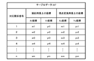
- FIG. 8 is a table 107a in which correction target coordinate corresponding points are extracted from the table data 107 and the coordinates before and after correction are shown.
- the table 107a the three-dimensional object distance necessary for correcting the table data 107 is also shown.
- the table 107a shown in FIG. 8 is merely illustrated for explanation, and need not be stored in the RAM 13 or the storage unit 14.
- the table correction unit 103 corrects the table data 107 by correcting the coordinate correspondence information related to the correction target coordinate corresponding point among the coordinate corresponding information related to each coordinate corresponding point of the table data 107.
- the correction target coordinate corresponding points o1, o2, o3,..., Oi are coordinates on these viewpoint conversion images, that is, coordinates in the virtual viewpoint coordinate system V, (xv_o1, yv_o1), ( xv_o2, yv_o2), (xv_o3, yv_o3), ..., (xv_oi, yv_oi), (xv_o1 ', yv_o1'), (xv_o2 ', yv_o2'), (xv_o3 ', yv_o3'), Corrections are made to (xv_oi ′, yv_oi ′), respectively. As described above, the table correction unit 103 performs correction using the three-dimensional object distance.
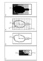
- FIG. 9 (1) shows a captured image 505 of the front camera 20a.
- FIG. 9B is a diagram showing a distance image 506 acquired by the distance detection unit 30, and
- FIG. 9C is a diagram showing a distance image 507 acquired by an ideal distance detection unit.
- the distance is represented by shading.
- the captured image 505 includes a three-dimensional object 51 located on the left hand and white lines LL and LR extending upward from below the center.
- the marker 52 is at the lower part of FIG. 9 (1), and the horizon 54 is at the upper part of FIG.
- a distance image 507 shown in FIG. 9 (3) is obtained.
- the entire shape of the three-dimensional object 51 is measured as indicated by reference numeral 511.
- FIG. 10A is an enlarged view of the vicinity of the reference numeral 510 in FIG. 9B and the outline of the three-dimensional object 51 is superimposed.
- FIG. 10 (2) is a diagram showing the boundaries of the measurement range in FIG. 10 (1).
- FIG. 10 (3) is a diagram in which coordinates corresponding pixels of the table data 107 are superimposed on the diagram of FIG. 10 (2).
- the coordinate corresponding pixels in FIG. 10 (3) are indicated by three types of cross marks ( ⁇ ), circle marks ( ⁇ ), and triangle marks ( ⁇ ).
- the cross mark indicates a point where distance information is obtained.
- a circle indicates a point corresponding to the three-dimensional object 51 and a point for which distance information is not obtained.
- the triangle mark indicates a point corresponding to the ground and the distance information is not obtained.
- the circle indicated by reference numeral 512 is a part of the three-dimensional object 51, it should be recognized at substantially the same distance as other parts of the three-dimensional object 51. Since the point indicated by the triangle indicated by reference numeral 513 is included in the ground, it should be recognized at substantially the same distance as the ground portion indicated by reference numeral 55.
- the distance correction unit 102 corrects the distance information as shown in FIG. That is, the distance correction unit 102 calculates the three-dimensional object distance shown in FIG.
- the table correction unit 103 corrects the table data 107 using the calculated three-dimensional object distance. As a result, appropriate conversion is performed on all coordinate-corresponding pixels in the table data 107.
- the image recognition unit 101 divides the photographed image into a plurality of regions, that is, segments by the segmentation process using the method using the color information described above with the photographed image 505 of the camera 20a shown in FIG. To do.
- the three-dimensional object 51 is recognized as one area indicated by reference numeral 601 and the marker 52 is recognized as four areas as indicated by reference numeral 603.
- Reference numerals 602 and 604 correspond to white road lines.
- Reference numeral 600 corresponds to the horizon.
- FIG. 11 (2) is a diagram in which symbols are attached to the respective segments shown in FIG. 11 (1) for convenience. As shown in FIG. 11 (2), the captured image is divided into nine segments SG11 to SG19 by the image recognition unit 101. However, in this segment division, it is not distinguished whether each segment is a three-dimensional object or a road surface.
- the distance correcting unit 102 corrects the distance of the coordinate corresponding point in the segment for each segment by any one of the following three methods.
- the first method is a simple average.
- the distance correction unit 102 calculates the average value of the distance information of all the coordinate corresponding points in the segment, and sets this average value as the three-dimensional object distance of all the coordinate corresponding points in the processing target segment. That is, according to the first method, all coordinate corresponding points in the segment have the same three-dimensional object distance.
- Circle mark 512 gives ⁇ dn / n which is an average value of distance information.
- the second method is a first order approximation.
- the distance correction unit 102 approximates the correlation between each coordinate value and distance information with a linear function for the coordinate corresponding points in the segment.
- the distance correction unit 102 determines the three-dimensional object distance of each coordinate corresponding point based on the approximate expression. That is, according to the second method, for example, the distance of the wall that faces the vehicle 1 diagonally can be accurately calculated.
- the least square method is used for the distance information dn (n is the number of cross marks included in the solid object 51) corresponding to the solid object 51 among the cross marks in FIG.
- the distance information of the circle 512 in FIG. 10 (3) is also obtained after using f (x, y). It becomes.
- the third method is multidimensional approximation.
- the approximation in the second method is a second-order or higher-order multidimensional function. According to the third method, the distance of an object having a complicated shape can also be accurately calculated.
- the coordinates of the point Pw1 indicating the distance information corresponding to the point Pr in the captured image 502 are as follows. Can be asking.
- xw1 d ⁇ cos ⁇ e ⁇ sin ⁇ a + xs
- yw1 d ⁇ cos ⁇ e ⁇ cos ⁇ a + ys
- zw1 R ⁇ sin ⁇ e + zs.
- the affine transformations shown in Equations 1 and 3 can be expressed as Equations 6 and 7 using the coordinate values shown in FIG.
- Equation 8 an equation for coordinate-converting the point Pr of the captured image 502 to the point of the viewpoint conversion image 503 is obtained.
- the point Pr in the captured image 502 is corrected from the point Pv to the point Pv1 in the viewpoint conversion image 503.
- the operation of the image processing apparatus 10 when the viewpoint conversion image is displayed on the user interface unit 40 will be described.
- the operation of the image processing apparatus 10 described below is executed every predetermined time.
- the execution subject of each step described below is the CPU 11.
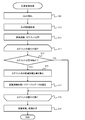
- the step diagram shown in FIG. 12 is an example, and the order of S11 and S12 may be reversed if the processing described below can be realized.
- the CPU 11 acquires a distance image from the distance detection unit 30 (S11).
- the CPU 11 acquires a captured image from the camera 20 (S12).
- the CPU 11 causes the image recognition unit 101 to process the distance image acquired in step S12 to execute segment division (S13).
- the example of step S13 is as described in FIG.
- the CPU 11 sequentially executes steps S15 to S18 described below for each segment calculated in step S13 (S14).
- the processing of S15 to S18 may be executed in parallel for all segments.
- an example will be described in which the processing target is changed and the segments are processed in order one by one.
- a segment to be processed is called a process target segment.
- the CPU 11 determines whether the processing target segment is a region corresponding to a three-dimensional object or a region corresponding to a road surface based on the distance information in the processing target segment (S15).
- Judgment whether the processing target segment is a three-dimensional object can be performed as follows, for example. That is, since the mounting position and mounting posture of the camera 20 are known, the associating unit 104 can calculate the relationship between the position in the captured image and the distance in advance by assuming that the imaging target is a road surface. Therefore, by comparing the difference between the distance information in the segment and the above-described distance calculated from the position in the captured image of the segment, it can be determined whether or not the subject in the segment is a road surface.
- the CPU 11 proceeds to step S16 when determining that the subject in the processing target segment is a three-dimensional object, and proceeds to step S18 when determining that the subject in the segment is a road surface. If it is determined that the distance is infinite or cannot be measured, and if it is determined that the subject of the processing target segment is empty, the process proceeds to step S18.
- step S16 the CPU 11 corrects the distance information of all coordinate corresponding points in the processing target segment using the distance correction unit 102. That is, the CPU 11 calculates a three-dimensional object distance.
- the CPU 11 causes the table correction unit 103 to rewrite all coordinate corresponding points in the processing target segment in the table data 107 (S17), and then proceeds to step S19.
- step S17 the table data 107 corrected in step S17 is discarded after execution of step S19 described later is completed. That is, the process of step S17 is correction for temporary copying of the table data 107.
- step S18 is executed. In this case, the CPU 11 proceeds to step S19 without causing the table correction unit 103 to correct the table data 107. That is, since no special process is performed in step S18, if it is determined that the road surface is in step S15 (S15: NO), the process may proceed to step S19 as it is.
- step S18 the CPU 11 determines whether all segments have been processed. When determining that there is an unprocessed segment, the CPU 11 sets the segment as a processing target and returns to step S15. If the CPU 11 determines that all segments have been processed, the process proceeds to step S19.
- step S19 the CPU 11 converts the photographed image of the camera 20 into a viewpoint converted image viewed from the virtual viewpoint 53 by using the table data 107 corrected by the image conversion unit 105 in step S17.
- step S19 the user interface control unit 106 outputs the viewpoint conversion image to the user interface unit 40, and the process ends.
- the image processing apparatus 10 includes a camera 20 that acquires a captured image, a distance detection unit 30 that acquires a distance image, and image recognition that extracts a region including a three-dimensional object region corresponding to the three-dimensional object in the captured image.
- Unit 101 distance correction unit 102 that calculates depth information of a three-dimensional object region based on a distance image, and three-dimensional object region calculated by distance correction unit 102 that is table data 107 that is coordinate conversion information for performing coordinate conversion of a captured image
- a table correction unit 103 that corrects the image based on the depth information
- an image conversion unit 105 that generates a viewpoint conversion image obtained by coordinate-converting the captured image using the table data 107 corrected by the table correction unit 103. Therefore, according to the present embodiment, the viewpoint conversion image can be obtained by processing the three-dimensional object region in the planar image three-dimensionally using the value of the distance image.
- the distance image acquisition range A30 in which the distance detection unit 30 acquires a distance image is smaller than the plane image acquisition range A20 in which the camera 20 acquires a plane image, and the plane image acquisition. It is set to overlap a part of the range A20. Therefore, according to the image processing apparatus 10 of the present embodiment, even when a distance image having a narrow measurement range compared to the camera 20 is used, a highly accurate viewpoint conversion image for a wide range of three-dimensional objects exceeding the measurement range of the distance image. Can be generated.
- the image recognition unit 101 extracts outlines of a plurality of segments including a three-dimensional object region based on at least one of brightness, brightness, saturation, and brightness of a captured image. Therefore, the image recognition unit 101 can easily divide the captured image into a plurality of segments including the three-dimensional object region.
- the table data 107 includes a plurality of combinations of conversion source coordinates on the captured image and conversion destination coordinates on the viewpoint conversion image. Based on the distance information of the three-dimensional object region in the distance image, the table correction unit 103 corrects the conversion destination coordinates, that is, the coordinates on the viewpoint conversion image, as shown in FIG. Thereby, in this embodiment, distance information can be given even outside the measurement range in which no distance image is acquired.
- the table data 107 is created in advance on the assumption that the subject in the captured image is an area on the road surface.
- the image recognition unit 101 divides the captured image into a plurality of segments for each subject included in the captured image.
- the table correction unit 103 determines whether or not the plurality of segments are solid object areas based on the distance image (S15 in FIG. 12), and corresponds to the conversion source coordinates in the segments determined to be solid object areas.
- the conversion destination coordinates are corrected in the table data 107 (S17).
- the table data 107 is calculated on the assumption that the subject of the photographed image exists within the reference height plane.
- the table correction unit 103 calculates the height of the subject from the reference height plane 501 and the position of the subject on the reference height plane using the depth information of the three-dimensional object region calculated by the distance correction unit 102. Further, the table correction unit 103 corrects the table data 107 using the viewpoint conversion reference position, the calculated height of the subject from the reference height plane, and the calculated position of the subject on the reference height plane.
- the table data 107 in the first embodiment indicates a correspondence relationship between the point Pr on the captured image and the point Pv on the viewpoint conversion image represented by the above-described Expression 5.
- table data 107 may indicate the correspondence between the point Pr on the photographed image represented by Equation 1 and the point Pw on the three-dimensional space.
- table data 107b it will be referred to as table data 107b below.
- the captured image projected on the three-dimensional section is deformed by correcting the table data 107b.
- the image conversion unit 105 creates an image obtained by capturing a captured image projected on the three-dimensional space from a virtual viewpoint, that is, a viewpoint converted image.
- FIG. 13 shows an example of the table data 107b.
- the table data 107b indicates the correspondence between the point Pr on the photographed image 502 expressed by Equation 1 and the point Pw in the three-dimensional space.
- a viewpoint conversion image can be created using the table data 107b even when a virtual viewpoint that is not assumed in advance is set by the user.
- the table data 107 of the first embodiment was created in advance under the assumption that all subjects are on the road surface. However, the table data 107 may be created at any time without being created in advance. In this case, table data 107 is created in the process shown in FIG. That is, in step S17, a corresponding portion of the table data 107 is created. By creating the table data 107 as needed, the amount of storage area used can be reduced.
- the vehicle 1 includes four cameras: a front camera 20a, a left camera 20b, a right camera 20c, and a rear camera 20d. However, the vehicle 1 may be provided with at least one camera. The vehicle 1 may include five or more cameras.
- the image recognition unit 101 divides a captured image into a plurality of regions by performing segment division processing.
- the table correction unit 103 corrects the table data 107 using the coordinate corresponding point of the region corresponding to the three-dimensional object as a processing target.
- the image recognition unit 101 may specify only the area corresponding to the three-dimensional object in the captured image. For example, by extracting a part of the depth image where the depth information does not change stepwise, and specifying the area of the same subject corresponding to that part in the photographed image, the area corresponding to the three-dimensional object is identified in the photographed image. Is possible.
- the table data 107 is created in advance under the assumption that all subjects are present on the road surface.
- the table data 107 may be created in advance under the assumption that it exists along a certain three-dimensional shape.
- the table data 107 may be created by setting a sphere with the vehicle center as the origin.
- the above components, functions, and the like may be realized by software by interpreting and executing a program that realizes each function by the processor.
- Information such as programs, tables, and files for realizing each function can be stored in a memory, a recording device such as a hard disk or SSD, or a recording medium such as an IC card, SD card, or DVD.
- control lines and information lines indicate what is considered necessary for the explanation, and not all control lines and information lines on the product are necessarily shown. Actually, it may be considered that almost all the components are connected to each other.
Landscapes
- Engineering & Computer Science (AREA)
- Multimedia (AREA)
- Physics & Mathematics (AREA)
- General Physics & Mathematics (AREA)
- Theoretical Computer Science (AREA)
- Mechanical Engineering (AREA)
- Signal Processing (AREA)
- Computer Vision & Pattern Recognition (AREA)
- Closed-Circuit Television Systems (AREA)
- Image Processing (AREA)
- Traffic Control Systems (AREA)
- Image Analysis (AREA)
Applications Claiming Priority (2)
| Application Number | Priority Date | Filing Date | Title |
|---|---|---|---|
| JP2018-077449 | 2018-04-13 | ||
| JP2018077449A JP7074546B2 (ja) | 2018-04-13 | 2018-04-13 | 画像処理装置および方法 |
Publications (1)
| Publication Number | Publication Date |
|---|---|
| WO2019198399A1 true WO2019198399A1 (ja) | 2019-10-17 |
Family
ID=68163565
Family Applications (1)
| Application Number | Title | Priority Date | Filing Date |
|---|---|---|---|
| PCT/JP2019/009588 Ceased WO2019198399A1 (ja) | 2018-04-13 | 2019-03-11 | 画像処理装置および方法 |
Country Status (2)
| Country | Link |
|---|---|
| JP (1) | JP7074546B2 (https=) |
| WO (1) | WO2019198399A1 (https=) |
Cited By (3)
| Publication number | Priority date | Publication date | Assignee | Title |
|---|---|---|---|---|
| CN113436241A (zh) * | 2021-06-25 | 2021-09-24 | 兰剑智能科技股份有限公司 | 一种采用深度信息的干涉校验方法及系统 |
| CN115434519A (zh) * | 2022-09-29 | 2022-12-06 | 中铁八局集团第一工程有限公司 | 电动式钢筋预绑扎台车 |
| CN119761310A (zh) * | 2024-12-27 | 2025-04-04 | 北京市测绘设计研究院 | 三维数据的基准转换方法、装置、计算机设备和存储介质 |
Families Citing this family (2)
| Publication number | Priority date | Publication date | Assignee | Title |
|---|---|---|---|---|
| JP2024089707A (ja) * | 2022-12-22 | 2024-07-04 | 株式会社Jvcケンウッド | 三次元情報補正装置及び三次元情報補正方法 |
| KR102893481B1 (ko) * | 2024-10-21 | 2025-12-01 | 케이엠아이에스 주식회사 | 카메라 영상을 이용한 지표면과 장애물 인식 단말 및 인식 방법 |
Citations (4)
| Publication number | Priority date | Publication date | Assignee | Title |
|---|---|---|---|---|
| JP2009118415A (ja) * | 2007-11-09 | 2009-05-28 | Alpine Electronics Inc | 鳥瞰画像生成装置および方法 |
| JP2011188335A (ja) * | 2010-03-10 | 2011-09-22 | Clarion Co Ltd | 車両用周囲監視装置 |
| JP2012147149A (ja) * | 2011-01-11 | 2012-08-02 | Aisin Seiki Co Ltd | 画像生成装置 |
| JP2018014583A (ja) * | 2016-07-20 | 2018-01-25 | クラリオン株式会社 | 画像処理装置 |
-
2018
- 2018-04-13 JP JP2018077449A patent/JP7074546B2/ja not_active Expired - Fee Related
-
2019
- 2019-03-11 WO PCT/JP2019/009588 patent/WO2019198399A1/ja not_active Ceased
Patent Citations (4)
| Publication number | Priority date | Publication date | Assignee | Title |
|---|---|---|---|---|
| JP2009118415A (ja) * | 2007-11-09 | 2009-05-28 | Alpine Electronics Inc | 鳥瞰画像生成装置および方法 |
| JP2011188335A (ja) * | 2010-03-10 | 2011-09-22 | Clarion Co Ltd | 車両用周囲監視装置 |
| JP2012147149A (ja) * | 2011-01-11 | 2012-08-02 | Aisin Seiki Co Ltd | 画像生成装置 |
| JP2018014583A (ja) * | 2016-07-20 | 2018-01-25 | クラリオン株式会社 | 画像処理装置 |
Cited By (4)
| Publication number | Priority date | Publication date | Assignee | Title |
|---|---|---|---|---|
| CN113436241A (zh) * | 2021-06-25 | 2021-09-24 | 兰剑智能科技股份有限公司 | 一种采用深度信息的干涉校验方法及系统 |
| CN115434519A (zh) * | 2022-09-29 | 2022-12-06 | 中铁八局集团第一工程有限公司 | 电动式钢筋预绑扎台车 |
| CN115434519B (zh) * | 2022-09-29 | 2023-08-22 | 中铁八局集团第一工程有限公司 | 电动式钢筋预绑扎台车 |
| CN119761310A (zh) * | 2024-12-27 | 2025-04-04 | 北京市测绘设计研究院 | 三维数据的基准转换方法、装置、计算机设备和存储介质 |
Also Published As
| Publication number | Publication date |
|---|---|
| JP7074546B2 (ja) | 2022-05-24 |
| JP2019185520A (ja) | 2019-10-24 |
Similar Documents
| Publication | Publication Date | Title |
|---|---|---|
| JP5491235B2 (ja) | カメラキャリブレーション装置 | |
| US9858639B2 (en) | Imaging surface modeling for camera modeling and virtual view synthesis | |
| WO2019198399A1 (ja) | 画像処理装置および方法 | |
| JP6891954B2 (ja) | 物体検知装置、物体検知方法、及びプログラム | |
| JP5944687B2 (ja) | 外因パラメータのみのサラウンドビューカメラ自動較正 | |
| JP3284190B2 (ja) | ステレオカメラの画像補正装置 | |
| US20100246901A1 (en) | Operation Support System, Vehicle, And Method For Estimating Three-Dimensional Object Area | |
| JP5455124B2 (ja) | カメラ姿勢パラメータ推定装置 | |
| US20080181488A1 (en) | Camera calibration device, camera calibration method, and vehicle having the calibration device | |
| JP5456330B2 (ja) | 画像表示装置及びそのカメラ取り付け角度算出方法 | |
| KR20220113781A (ko) | 환경의 지형을 측정하는 방법 | |
| CN110832851B (zh) | 图像处理装置、图像变换方法 | |
| JP2022547531A (ja) | センサフュージョンに基づく知覚的に向上したサラウンドビュー | |
| JP2020537216A (ja) | 画像処理方法及び装置 | |
| JP5178454B2 (ja) | 車両周囲監視装置及び車両周囲監視方法 | |
| KR20170001765A (ko) | Avm 시스템의 공차 보정 장치 및 방법 | |
| JP7196920B2 (ja) | 運転支援装置および運転支援方法、プログラム | |
| JP2009077022A (ja) | 運転支援システム及び車両 | |
| WO2015182771A1 (ja) | 撮像装置、画像処理装置、画像処理方法およびコンピュータプログラム | |
| TWM591940U (zh) | 全景停車輔助系統及其裝置 | |
| JP6734136B2 (ja) | 画像処理装置 | |
| JP2013200840A (ja) | 映像処理装置、映像処理方法、映像処理プログラム、及び映像表示装置 | |
| JP7652739B2 (ja) | 画像処理装置及び画像処理方法 | |
| KR101592793B1 (ko) | 영상 왜곡 보정 장치 및 방법 | |
| US20240404293A1 (en) | Method for Calibrating an Assistance System of a Civil Motor Vehicle |
Legal Events
| Date | Code | Title | Description |
|---|---|---|---|
| 121 | Ep: the epo has been informed by wipo that ep was designated in this application |
Ref document number: 19784991 Country of ref document: EP Kind code of ref document: A1 |
|
| NENP | Non-entry into the national phase |
Ref country code: DE |
|
| 122 | Ep: pct application non-entry in european phase |
Ref document number: 19784991 Country of ref document: EP Kind code of ref document: A1 |