WO2019198294A1 - 表示装置 - Google Patents
表示装置 Download PDFInfo
- Publication number
- WO2019198294A1 WO2019198294A1 PCT/JP2019/001398 JP2019001398W WO2019198294A1 WO 2019198294 A1 WO2019198294 A1 WO 2019198294A1 JP 2019001398 W JP2019001398 W JP 2019001398W WO 2019198294 A1 WO2019198294 A1 WO 2019198294A1
- Authority
- WO
- WIPO (PCT)
- Prior art keywords
- unit
- display
- winding
- display device
- display unit
- Prior art date
- Legal status (The legal status is an assumption and is not a legal conclusion. Google has not performed a legal analysis and makes no representation as to the accuracy of the status listed.)
- Ceased
Links
Images








Classifications
-
- G—PHYSICS
- G09—EDUCATION; CRYPTOGRAPHY; DISPLAY; ADVERTISING; SEALS
- G09F—DISPLAYING; ADVERTISING; SIGNS; LABELS OR NAME-PLATES; SEALS
- G09F9/00—Indicating arrangements for variable information in which the information is built-up on a support by selection or combination of individual elements
-
- G—PHYSICS
- G09—EDUCATION; CRYPTOGRAPHY; DISPLAY; ADVERTISING; SEALS
- G09F—DISPLAYING; ADVERTISING; SIGNS; LABELS OR NAME-PLATES; SEALS
- G09F9/00—Indicating arrangements for variable information in which the information is built-up on a support by selection or combination of individual elements
- G09F9/30—Indicating arrangements for variable information in which the information is built-up on a support by selection or combination of individual elements in which the desired character or characters are formed by combining individual elements
-
- H—ELECTRICITY
- H05—ELECTRIC TECHNIQUES NOT OTHERWISE PROVIDED FOR
- H05B—ELECTRIC HEATING; ELECTRIC LIGHT SOURCES NOT OTHERWISE PROVIDED FOR; CIRCUIT ARRANGEMENTS FOR ELECTRIC LIGHT SOURCES, IN GENERAL
- H05B33/00—Electroluminescent light sources
- H05B33/02—Details
-
- H—ELECTRICITY
- H05—ELECTRIC TECHNIQUES NOT OTHERWISE PROVIDED FOR
- H05K—PRINTED CIRCUITS; CASINGS OR CONSTRUCTIONAL DETAILS OF ELECTRIC APPARATUS; MANUFACTURE OF ASSEMBLAGES OF ELECTRICAL COMPONENTS
- H05K7/00—Constructional details common to different types of electric apparatus
-
- H—ELECTRICITY
- H10—SEMICONDUCTOR DEVICES; ELECTRIC SOLID-STATE DEVICES NOT OTHERWISE PROVIDED FOR
- H10K—ORGANIC ELECTRIC SOLID-STATE DEVICES
- H10K59/00—Integrated devices, or assemblies of multiple devices, comprising at least one organic light-emitting element covered by group H10K50/00
Definitions
- the present invention relates to a display device.
- a display device having a flexible display portion and a display device having a rollable display portion are known.
- a flexible display unit is wound in the same direction many times, the display unit is warped in accordance with the wound direction (hereinafter referred to as having a curl). Flexibility may be reduced.
- curling occurs and the display unit is damaged if the display unit is forcibly expanded to a flat state.
- Patent Document 1 discloses a first roller that winds a flexible thin display unit, and a roller controller that rotates the first roller in a first direction and a second direction opposite to the first direction. And a display device that controls the thin display unit to be selectively wound in either the first direction or the second direction.
- Patent Document 2 discloses a display device having a roller that winds a flexible display portion in both a first direction and a second direction opposite to the first direction.
- the present invention has been made in view of the above problems, and an object of the present invention is to prevent damage to the display unit due to curling at the connecting portion between the display unit and the winding unit.
- the display device includes a sheet-like display unit having a display surface for displaying an image, a storage unit for storing the display unit, and a first direction in which the display surface is disposed inside the storage unit.
- a winding unit that winds up the display unit in a second direction in which the display surface is outside, a switching unit that switches the winding direction to the first direction or the second direction, the winding unit, and the display unit.
- a connecting portion that bends according to the winding direction.
- an organic EL display device has been exemplified as a disclosure example.
- a liquid crystal display device, another self-luminous display device, or an electron having an electrophoretic element or the like Any flat panel display device such as a paper display device may be used.
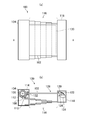
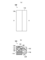
- FIG. 1A to FIG. 5B are diagrams each schematically showing the display device 100 according to the first embodiment.
- FIGS. 1A, 2 ⁇ / b> A, 3 ⁇ / b> A, 4 ⁇ / b> A, and 5 ⁇ / b> A are plan views viewed from the top surface of the display device 100.
- 1 (b), FIG. 2 (b), FIG. 3 (b), FIG. 4 (b) and FIG. 5 (b) are respectively shown in FIG. 1 (a), FIG. 2 (a),
- FIGS. 4A and 4B are cross-sectional views taken along lines II, II-II, III-III, IV-IV, and VV in FIGS. 4A and 5A, respectively.
- FIG. 1A and FIG. 1B are diagrams showing a state in which the display unit 102 is all pulled out from the first storage unit 104.
- 2A and 2B are views showing a state in which a part of the display unit 102 is wound in the first direction 602 (see FIG. 6).
- FIG. 3A and FIG. 3B are diagrams showing a state where the display unit 102 is entirely wound in the first direction 602.
- FIGS. 4A and 4B are views showing a state in which a part of the display unit 102 is wound in the second direction 604 (see FIG. 6).
- FIGS. 5A and 5B are diagrams illustrating a state in which the display unit 102 is entirely wound in the second direction 604.
- the display device 100 includes a display unit 102, a first storage unit 104, a winding unit 106, a detection unit 606 (see FIG. 6), an actuator 108, a control unit 110, a storage unit (not shown), and switching. Part (not shown), connection part 112, roll pair 114, drawer structure 116, second storage part 118, drive circuit 120, connection line 122, control circuit 124, fixing part 126, Have
- the display unit 102 is in the form of a sheet and has a display surface 128 for displaying an image.
- the display unit 102 is a thin panel that displays an image, such as an organic EL panel.
- the display unit 102 includes an array layer in which a TFT (Thin Film Transistor) and a capacitor are formed, an organic EL (Electro Luminescence) layer that emits light, and the like.
- the display unit 102 includes a display area 130, and the display area 130 includes a plurality of pixels each formed of a plurality of subpixels arranged in a matrix. The display area 130 displays an image when each pixel emits light.
- the display unit 102 is disposed between the first storage unit 104 and the second storage unit 118 and is stored in the first storage unit 104 in the direction from the second storage unit 118 toward the first storage unit 104.
- the display unit 102 is flexible so that the display unit 102 can be wound around the winding unit 106 in a stored state.
- the first storage unit 104 stores the display unit 102.
- the first storage unit 104 is a metal or resin casing, and includes a detection unit 606, a switching unit, a winding unit 106, a control unit 110, a storage unit, an actuator 108, and a connection unit. 112 is arranged.
- the control unit 110 rotates the winding unit 106 by controlling the actuator 108.
- the first storage unit 104 stores the display unit 102 connected to the winding unit 106 inside.
- the winding unit 106 is disposed in the first storage unit 104 and winds the display unit 102 in a first direction 602 in which the display surface 128 is on the inside or a second direction 604 in which the display surface 128 is on the outside.
- the winding unit 106 is disposed in the first storage unit 104 and connected to the display unit 102 via the connection unit 112.
- the winding unit 106 is pivoted clockwise (hereinafter referred to as a first direction 602) about the center of the winding unit 106 (hereinafter referred to as a winding shaft 608).
- the display unit 102 is wound up.
- FIGS. 4B and 5B the winding unit 106 rotates about the winding shaft 608 counterclockwise (hereinafter, referred to as a second direction 604), and the display unit 102. Wind up.
- the first storage unit 104 stores a part or all of the display unit 102 inside the casing.
- the end of the display unit 102 and the surface of the winding unit 106 are vertical.
- the display unit 102 in a state where a part of the display unit 102 is wound, the display unit 102 includes a part of the area including the display region 130 in the winding unit 106. It is wound up.
- the display unit 102 in a state where the display unit 102 is entirely stored in the first storage unit 104, the display unit 102 is a part of the vicinity of the entrance of the first storage unit 104. Most of the portion excluding the region of the portion is wound around the winding portion 106.
- the shape of the winding portion 106 may not be cylindrical.
- the winding unit 106 may be a polygonal column or may have a shape obtained by rounding the corners of the polygonal column. Further, the winding unit 106 may be rotated not only by the actuator 108 but also manually by, for example, a handle connected to the winding unit 106.
- the detection unit 606 detects the winding direction of the display unit 102.
- the detection unit 606 detects the winding direction by detecting contact with the winding unit 106 in a state where the connection unit 112 is bent. Specifically, this will be described with reference to FIG.
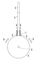
- FIG. 6 is a view showing a cross section of the display device 100.
- the detection unit 606 is disposed on each of the display surface 128 side and the back surface side of the connection unit 112.
- the detection unit 606 is, for example, a mechanical switch. When the display unit 102 is wound up, the detection unit 606 is pressed in contact with the winding unit 106.
- the detection unit 606 detects the winding direction of the display unit 102 when a switch arranged on either the display surface 128 side or the back surface side of the connection unit 112 is pressed according to the winding direction.
- the detection unit 606 may not be a mechanical switch.
- the detection unit 606 may be an optical sensor or a magnetic sensor.
- the control unit 110 controls the rotation of the winding unit 106 by the actuator 108, the display device 100 may not include the detection unit 606.
- the actuator 108 rotates the winding unit 106 in the first direction 602 or the second direction 604 under the control of the control unit 110.
- the actuator 108 is a motor, and rotates the winding unit 106 in the first direction 602 or the second direction 604 based on an instruction from the control unit 110.
- the control unit 110 controls the winding unit 106.
- the control unit 110 is an IC such as a microcomputer or FPGA, or a substrate on which the IC is arranged.
- the control unit 110 controls the rotation direction of the winding unit 106 and the rotation speed of the winding unit 106 via the switching unit.
- the control unit 110 controls the actuator 108 according to the information stored in the storage unit so that the winding unit 106 winds the display unit 102 in a winding direction different from the winding direction stored in the storage unit. Control.
- the control unit 110 Switches the rotation direction of the winding unit 106 to the second direction 604.
- the control unit 110 may alternately switch the rotation direction of the winding unit 106 between the first direction 602 and the second direction 604 each time the display unit 102 is pulled out from the first storage unit 104.
- the control unit 110 may alternately switch the rotation direction of the winding unit 106 between the first direction 602 and the second direction 604 every time the display unit 102 is pulled out from the first storage unit 104 a plurality of times.
- the switching unit switches the winding direction to the first direction 602 or the second direction 604.
- the switching unit is realized as a function of the control unit 110.
- the switching unit is a logic circuit included in an IC that is the control unit 110 and switches the rotation direction of the actuator 108.
- the switching unit may be a mechanical switch.
- the switching unit may be configured by a switch disposed outside the first storage unit 104 and a gear that switches the rotation direction of the switching unit by pressing the switch.
- the display unit 102 may be configured without the control unit 110, the detection unit 606, and the storage unit.
- the storage unit stores information related to the winding direction.
- the storage unit is a memory included in an IC such as a microcomputer or FPGA included in the control unit 110, or a memory connected to the IC.
- the storage unit stores information for identifying whether the winding direction detected by the detection unit 606 is the first direction 602 or the second direction 604 (hereinafter referred to as winding direction information).
- the storage unit may store the rotation direction of the actuator 108 controlled by the control unit 110 as winding direction information.
- the storage unit is preferably a non-volatile memory that holds stored information even when the display device 100 is powered off.
- the storage unit may be a volatile memory when it has a means for detecting the winding direction even when the power of the display unit 102 is turned off, such as a configuration in which a mechanical detector is provided. Good.
- connection unit 112 connects the winding unit 106 and the display unit 102 and bends according to the winding direction.
- the connection part 112 is a hinge. Details of the connection unit 112 will be described later.
- the roll pair 114 is arranged in the first storage unit 104. Specifically, the roll pair 114 is disposed near the opening 132 of the first storage unit 104 with the display unit 102 interposed therebetween. The roll pair 114 reduces sliding friction that occurs when the display unit 102 is wound around the winding unit 106. Note that the display device 100 may not include the roll pair 114.
- the drawer structure 116 is a mechanism that regulates the positional relationship between the first storage unit 104 and the second storage unit 118. Specifically, for example, as shown in FIG. 1B, the drawer structure 116 has a shape in which flat plates are connected in a stepped manner. With the display unit 102 all pulled out from the first storage unit 104, the drawer structure 116 is in the most extended state. Accordingly, the drawer structure 116 regulates the positional relationship between the first storage unit 104 and the second storage unit 118 so that the first storage unit 104 and the second storage unit 118 are not separated from each other by a predetermined distance.
- the drawer structure 116 expands and contracts. Specifically, for example, as shown in FIGS. 2B and 4B, in a state where a part of the display unit 102 is stored in the first storage unit 104, the drawer structure 116 has the structure shown in FIG. It is shortened to about half the length of the drawer structure 116 shown in b). Further, as shown in FIG. 3B and FIG. 5B, in the state where all the display units 102 are stored in the first storage unit 104, the drawer structure 116 becomes the shortest, and the first storage unit 104 Housed inside. When the drawer structure 116 expands and contracts, the size of the displayed image can be changed according to the size of the drawn area of the display device 100.
- the second storage unit 118 stores the fixed unit 126 and the like inside.
- the second storage unit 118 is a metal or resin casing, and includes a part of the display unit 102, a drive circuit 120, a connection line 122, a control circuit 124, and a fixed inside. Part 126 is arranged.
- the drive circuit 120 generates power and signals to be supplied to each pixel.
- the drive circuit 120 is an IC that generates power and signals supplied to each pixel.
- the drive circuit 120 applies a potential for conducting between the source and the drain to the drive transistor arranged in each pixel, and flows a current corresponding to the gradation value to each data signal line.
- the display unit 102 displays an image in the display area 130.
- the connection line 122 is formed of a conductive material, and electrically connects the drive circuit 120 and the control circuit 124.
- the control circuit 124 controls the operation of the drive circuit 120. Specifically, the control circuit 124 acquires an image signal and a power source from an external device (not shown). The control circuit 124 generates an image signal, a signal for controlling the timing of lighting the pixel, and the like based on the acquired image signal and power supply, and supplies the signal to the drive circuit 120.
- the fixing unit 126 is disposed in the second storage unit 118 and fixes the second storage unit 118 and the display unit 102.
- the fixing unit 126 has a rectangular parallelepiped shape, for example, one surface is fixed to the inner wall of the second storage unit 118, and the other surface fixes the end of the display unit 102. Thereby, the positional relationship between the display unit 102 and the second storage unit 118 is fixed.
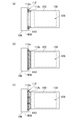
- FIG. 7A to FIG. 7C are diagrams showing the display device 100 in a plan view of the first embodiment.
- the configuration of the second storage unit 118 and the like is omitted in FIG.
- the connecting portion 112 is a hinge that connects the winding portion 106 and the display portion 102 and bends around the rotation shaft 610 of the connecting portion 112 according to the winding direction. is there.
- the connection unit 112 includes a winding unit side connection unit 112 a fixed to the winding unit 106 and a display unit side connection unit 112 b connected to the display unit 102.
- the winding part side connection part 112a and the display part side connection part 112b are connected so as to be bent around the rotation shaft 610.
- connection unit 112 may have a plurality of connection regions that are spaced apart from one side of the display unit 102. Specifically, as illustrated in FIG. 7A, the connection unit 112 is provided only at the upper and lower end portions of the display unit 102, and the display unit side connection unit 112 b provided at the end unit is the display unit 102. You may make it connect with. Further, as shown in FIG. 7B, the connection portion 112 may have a shape that does not break from the upper end to the lower end along the left side of the display portion 102. In this case, the display unit side connection unit 112 b provided over one side of the display unit 102 and the display unit 102 are connected. Further, as illustrated in FIG.
- connection unit 112 may have a shape having a cut in a part of the region from the upper end to the lower end along the left side of the display unit 102.
- the display unit side connection unit 112b is connected to the display unit 102 in a region where the cut is not provided.
- the control unit 110 determines whether or not all of the display unit 102 has been pulled out (S802). Specifically, the control unit 110 determines whether all of the display unit 102 has been pulled out based on the number of rotations of the winding unit 106. Further, the control unit 110 may determine whether or not the entire display unit 102 has been pulled out by a sensor or the like (not shown). In addition, the state where all are pulled out means a state where there is no portion where the display unit 102 and the winding unit 106 are in contact with each other, as shown in FIG.
- the control unit 110 reads the winding direction information stored in the storage unit (S804). Specifically, for example, when the immediately preceding winding direction is the first direction 602, the storage unit stores winding direction information indicating the first direction 602. Therefore, the control unit 110 reads the winding direction information indicating the first direction 602 from the storage unit.
- control unit 110 controls the actuator 108 while maintaining the winding direction of the display unit 102 at that time.
- the control unit 110 determines the winding direction represented by the read winding direction information (S806), and when the read winding direction information represents the first direction 602, the control unit 110 The actuator 108 is controlled so that the winding unit 106 winds up the display unit 102 in the second direction 604 (S808). On the other hand, when the read winding direction information indicates the second direction 604, the control unit 110 controls the actuator 108 so that the winding unit 106 winds the display unit 102 in the first direction 602 (S810). .
- the detection unit 606 detects the winding direction (S812). Specifically, the detection unit 606 takes up the display unit 102 by pressing a switch disposed on either the display surface 128 side or the back side of the connection unit 112 according to the winding direction. Detect direction. The storage unit stores winding direction information indicating the winding direction detected by the detection unit 606.
- control unit 110 may change the winding direction information stored in the storage unit to the winding direction information representing the first direction 602 after S808. Good.
- the control unit 110 may change the winding direction information stored in the storage unit to winding direction information representing the second direction 604 after S810. Further, according to the flowchart, the control unit 110 performs control so as to alternately switch the first direction 602 and the second direction 604, but may perform control so as to switch the winding direction every plural times.
- the display unit 102 it is possible to make the display unit 102 less likely to be curled by periodically changing the winding direction of the roller. Furthermore, since the connection portion 112 that is particularly likely to be damaged is formed of a hinge, the display device 100 can be made more difficult to break.
- FIG. 9 is a diagram illustrating a cross-section of the display device 100 according to a modification of the first embodiment.
- FIGS. 10A to 10C are diagrams showing the display device 100 in a plan view in the modification of the first embodiment.
- the connecting portion 112 in this modification is a hinge and may have two rotating shafts 610.
- connection unit 112 includes a winding unit side connection unit 112a fixed to the winding unit 106, a display unit side connection unit 112b connected to the display unit 102, and a winding unit side connection unit 112a. And an intermediate connection part 112c arranged between the display part side connection parts 112b.
- the winding portion side connecting portion 112a and the intermediate connecting portion 112c are connected so as to be bent around the rotation shaft 610.
- the intermediate connection part 112c and the display part side connection part 112b are connected so that it can be bent.
- connection unit 112 may have a plurality of connection regions that are spaced apart from one side of the display unit 102. Specifically, as illustrated in FIG. 10A, the connection unit 112 is provided only at the upper and lower end portions of the display unit 102, and the display unit side connection unit 112 b provided at the end unit is the display unit 102. You may make it connect with. Further, as shown in FIG. 10B, the connecting portion 112 may have a shape that does not break from the upper end to the lower end along the left side of the display portion 102. In this case, the display unit side connection unit 112 b provided over one side of the display unit 102 and the display unit 102 are connected. Further, as illustrated in FIG.
- connection unit 112 may have a shape having a cut in a part of the region from the upper end to the lower end along the left side of the display unit 102.
- the display unit side connection unit 112b is connected to the display unit 102 in a region where the cut is not provided.
- the detection unit 606 is provided in the connection unit 112, but may be provided in the winding unit 106 as illustrated in FIG. 9. In the case of FIG. 6, the detection unit 606 has detected the winding direction by contact determination with the winding unit 106, but when the detection unit 606 is provided in the winding unit 106 as illustrated in FIG. 9, the detection unit 606. The winding direction is detected by contact determination with the display unit 102.
- the bending property of the connecting portion 112 in the first direction 602 and the second direction 604 is improved, so that the connecting portion 112 that connects the display portion 102 and the winding portion 106 is less likely to be damaged. can do.
- FIG. 11 is a diagram illustrating a cross-section of the display device 100 according to the second embodiment.
- FIG. 12 is a diagram illustrating a cross-section of the display device 100 according to a modification of the second embodiment.
- FIG. 13A and FIG. 13B are diagrams illustrating the display device 100 in a plan view of the second embodiment.
- connection part 112 in this embodiment is an elastic body.
- the connection portion 112 is formed of an elastic body that can be bent in a first direction 602 and a second direction 604 such as rubber or a spring.
- the connection portion 112 may be formed of a single elastic member and connected to the winding portion 106 and the display portion 102.
- the connection part 112 may be comprised with the some elastic member.
- the connection unit 112 is fixed to the display surface side connection unit 1202 fixed to the display surface 128 and spaced apart from the display surface side connection unit 1202 on the back side of the display surface 128.
- the back surface side connection portion 1204 may be included.
- connection unit 112 may have a plurality of connection regions that are spaced apart from one side of the display unit 102.
- the connection portion 112 may have a shape that does not break from the upper end to the lower end along the left side of the display portion 102.
- the connection unit 112 and the display unit 102 provided over one side of the display unit 102 are connected.
- the connecting portion 112 may have a shape having a cut in a part of the region from the upper end to the lower end along the left side of the display portion 102. In this case, the connection unit 112 is connected to the display unit 102 in an area where the cut is not provided.
- the detection unit 606 is provided in the connection unit 112, but may be provided on the front and back of the display unit 102 as illustrated in FIGS. 11 and 12. As in the case of FIG. 6, the detection unit 606 detects the winding direction by determining contact with the winding unit 106.
- connection portion 112 that connects the display portion 102 and the winding portion 106 is less likely to be damaged by improving the flexibility of the connection portion 112 in the first direction 602 and the second direction 604. Can do.
- FIG. 14 is a diagram illustrating a cross section of the display device 100 according to the third embodiment.
- FIG. 15A to FIG. 15C are diagrams illustrating the display device 100 in a plan view of the third embodiment.
- connection unit 112 in this embodiment includes a winding unit side connection unit 1402 and a display unit side connection unit 1404.
- the connection portion 112 is a display provided with a winding portion side connection portion 1402 having a guide bar fixed to the winding portion 106, and a hole through which the guide bar is inserted.
- the guide bar is, for example, a semi-annular shape.
- the guide bar is fixed to the winding part 106 so that the semicircular cut-out part is on the winding part 106 side.
- the hole is provided at a position corresponding to the guide bar with a diameter larger than the diameter of the guide bar so that the guide bar is inserted.
- connection unit 112 may have a plurality of connection regions that are spaced apart from one side of the display unit 102. Specifically, as illustrated in FIG. 15A, the connection unit 112 is provided only at the upper and lower end portions and the center portion of the display unit 102, and the display unit side connection unit 1404 provided at the relevant portion displays the connection unit 112. It may be connected to the unit 102. Further, as shown in FIGS. 15B and 15C, the connecting portion 112 may have a shape that does not break from the upper end to the lower end along the left side of the display portion 102. In this case, the display unit side connection unit 1404 provided over one side of the display unit 102 and the display unit 102 are connected.
- the number of guide bars and holes may be at least 2 or more.
- the number of guide bars and holes may be three, and as shown in FIG. 15 (c), the number of guide bars and holes is eight. Also good.
- the connecting portion is formed in a structure like a loose-leaf binding tool. Accordingly, as in the first and second embodiments, the connection portion connecting the display unit 102 and the winding unit 106 is broken by improving the flexibility of the connection unit in the first direction and the second direction. Can be made difficult to occur.
Landscapes
- Engineering & Computer Science (AREA)
- Physics & Mathematics (AREA)
- General Physics & Mathematics (AREA)
- Theoretical Computer Science (AREA)
- Devices For Indicating Variable Information By Combining Individual Elements (AREA)
- Microelectronics & Electronic Packaging (AREA)
- Electroluminescent Light Sources (AREA)
- Insertion, Bundling And Securing Of Wires For Electric Apparatuses (AREA)
Abstract
表示部と巻き取り部の接続部において、巻き癖がつくことによる表示部の破損を防止する。 表示装置であって、画像を表示する表示面を有するシート状の表示部と、前記表示部を格納する格納部と、前記格納部に配置され、前記表示面が内側となる第1方向または前記表示面が外側となる第2方向に前記表示部を巻き取る巻き取り部と、巻き取り方向を前記第1方向または前記第2方向に切り替える切り替え部と、前記巻き取り部と前記表示部とを接続し、前記巻き取り方向に応じて屈曲する接続部と、を有する。
Description
本発明は、表示装置に関する。
可撓性を有する表示部を有する表示装置や、巻き取り可能な表示部を有する表示装置が知られている。可撓性を有する表示部は、何度も同じ方向に巻き取られると、巻き取られた方向に応じて表示部が反った状態となり(以下、巻き癖がついた、と表現する)、可撓性が低下することがある。また、収納された状態で長時間経過した場合も巻き癖がつき,表示部を強制的に平坦な状態に展開しようとすると表示部が破損する。
そこで、例えば、下記特許文献1は、可撓性を有する薄型表示部を巻き取る第1ローラと、第1ローラを第1方向及び第1方向とは反対の第2方向に回転させるローラコントローラとを含み、薄型表示部が第1の方向および第2の方向のいずれかに選択的に巻かれるように制御する表示装置を開示している。
また、下記特許文献2は、可撓性を有する表示部を、第1の方向及び第1の方向とは反対の第2の方向の両方に巻きとるローラを有する表示装置を開示している。
表示部を巻き取ると、表示部の引き出された部分だけでなく、表示部と巻き取り部との接続部にも巻き癖がつく。ローラの巻き取り方向が、第1方向から第2方向に変わると、接続部における表示部と巻き取り部の表面とのなす角度は、180度変化する。従って、巻き癖による表示部の破損は、特に接続部付近で発生する。
本発明は上記課題に鑑みてなされたものであって、その目的は、表示部と巻き取り部の接続部において、巻き癖がつくことによる表示部の破損を防止することである。
本開示の表示装置は、画像を表示する表示面を有するシート状の表示部と、前記表示部を格納する格納部と、前記格納部に配置され、前記表示面が内側となる第1方向または前記表示面が外側となる第2方向に前記表示部を巻き取る巻き取り部と、巻き取り方向を前記第1方向または前記第2方向に切り替える切り替え部と、前記巻き取り部と前記表示部とを接続し、前記巻き取り方向に応じて屈曲する接続部と、を有することを特徴とする。
以下に、本発明の各実施の形態について、図面を参照しつつ説明する。なお、開示はあくまで一例に過ぎず、当業者において、発明の主旨を保っての適宜変更について容易に想到し得るものについては、当然に本発明の範囲に含有されるものである。また、図面は、説明をより明確にするため、実際の態様に比べ、各部の幅、厚さ、形状等について模式的に表される場合があるが、あくまで一例であって、本発明の解釈を限定するものではない。また、本明細書と各図において、既出の図に関して前述したものと同様の要素には、同一の符号を付して詳細な説明を適宜省略することがある。
また、下記の各実施形態においては、開示例として有機EL表示装置の場合を例示したが、その他の適用例として、液晶表示装置、その他の自発光型表示装置、あるいは電気泳動素子等を有する電子ペーパー型表示装置等あらゆるフラットパネル型の表示装置が挙げられる。また、中小型から大型まで、特に限定することなく適用が可能であることは言うまでもない。
[第1の実施形態]
まず、第1の実施形態に係る表示装置100の機械的な構成について説明する。図1(a)乃至図5(b)は、いずれも第1の実施形態に係る表示装置100の概略を示す図である。図1(a)、図2(a)、図3(a)、図4(a)及び図5(a)は、表示装置100の上面から見た平面図である。図1(b)、図2(b)、図3(b)、図4(b)及び図5(b)は、それぞれ図1(a)、図2(a)、図3(a)、図4(a)及び図5(a)のI-I断面、II-II断面、III-III断面、IV-IV断面及びV-V断面を示す図である。
まず、第1の実施形態に係る表示装置100の機械的な構成について説明する。図1(a)乃至図5(b)は、いずれも第1の実施形態に係る表示装置100の概略を示す図である。図1(a)、図2(a)、図3(a)、図4(a)及び図5(a)は、表示装置100の上面から見た平面図である。図1(b)、図2(b)、図3(b)、図4(b)及び図5(b)は、それぞれ図1(a)、図2(a)、図3(a)、図4(a)及び図5(a)のI-I断面、II-II断面、III-III断面、IV-IV断面及びV-V断面を示す図である。
また、図1(a)及び図1(b)は、表示部102を第1格納部104から全て引き出した状態を示す図である。図2(a)及び図2(b)は、表示部102の一部を第1方向602(図6参照)に巻き取った状態を示す図である。図3(a)及び図3(b)は、表示部102を第1方向602に全て巻き取った状態を示す図である。図4(a)及び図4(b)は、表示部102の一部を第2方向604(図6参照)に巻き取った状態を示す図である。図5(a)及び図5(b)は、表示部102を第2方向604に全て巻き取った状態を示す図である。
表示装置100は、表示部102と、第1格納部104と、巻き取り部106と、検出部606(図6参照)と、アクチュエータ108と、制御部110と、記憶部(図示なし)、切り替え部(図示なし)と、接続部112と、ロール対114と、引き出し構造体116と、第2格納部118と、駆動回路120と、接続線122と、制御回路124と、固定部126と、を有する。
表示部102は、シート状であって、画像を表示する表示面128を有する。具体的には、表示部102は、例えば有機ELパネルなどの画像を表示する薄型のパネルである。表示部102は、TFT(Thin Film Transistor)やコンデンサが形成されたアレイ層や、光を発する有機EL(Electro Luminescence)層等が設けられる。表示部102は、表示領域130を有し、表示領域130は、それぞれ複数の副画素で構成された複数の画素がマトリクス状に配置される。表示領域130は、各画素が発光することにより画像を表示する。
また、表示部102は、第1格納部104と第2格納部118の間に配置され、第2格納部118から第1格納部104へ向かう方向に向かって、第1格納部104に格納される。表示部102は、格納された状態で巻き取り部106の周りに巻きつけられるように可撓性を有する。
第1格納部104は、表示部102を格納する。具体的には、第1格納部104は、金属製または樹脂製の筐体であって、内部に検出部606、切り替え部、巻き取り部106、制御部110、記憶部、アクチュエータ108及び接続部112が配置される。後述するように制御部110は、アクチュエータ108を制御することにより、巻き取り部106を回転させる。これにより、第1格納部104は、巻き取り部106と接続された表示部102を内部に格納する。
巻き取り部106は、第1格納部104に配置され、表示面128が内側となる第1方向602または表示面128が外側となる第2方向604に表示部102を巻き取る。具体的には、巻き取り部106は、第1格納部104に配置され、接続部112を介して表示部102と接続される。巻き取り部106は、図2(b)及び図3(b)に示すように、時計回り(以下、第1方向602とする)に巻き取り部106の中心を軸(以下、巻き取り軸608とする)として回転し表示部102を巻き取る。また、巻き取り部106は、図4(b)及び図5(b)に示すように、反時計回り(以下、第2方向604とする)に巻き取り軸608を中心に回転し表示部102を巻き取る。
これにより、第1格納部104は、表示部102の一部または全部を筐体の内部に格納する。図1(b)に示すように、表示部102が全て第1格納部104から引き出された状態では、表示部102の端部と巻き取り部106の表面は垂直になる。図2(b)及び図4(b)に示すように、表示部102の一部が巻き取られた状態では、表示部102は、表示領域130を含む一部の領域が巻き取り部106に巻き取られる。さらに、図3(b)及び図5(b)に示すように、表示部102が全て第1格納部104に格納された状態では、表示部102は、第1格納部104の入口近傍の一部の領域を除く大部分が巻き取り部106に巻き取られる。
図1(a)乃至図6に示した巻き取り部106は、円柱状の形状であるが、巻き取り部106の形状は、円柱状でなくてもよい。例えば、巻き取り部106は、多角柱でもよいし、多角柱の角を丸めた形状であってもよい。また、巻き取り部106は、アクチュエータ108によって回転するだけでなく、例えば巻き取り部106と接続されたハンドルによって、手動で回転するようにしてもよい。
検出部606は、表示部102の巻き取り方向を検出する。例えば、検出部606は、接続部112が屈曲した状態で巻き取り部106との接触を検出することにより巻き取り方向を検出する。具体的には、図6を用いて説明する。図6は、表示装置100の断面を示す図である。検出部606は、接続部112の表示面128側及び裏面側のそれぞれに配置される。検出部606は、例えば、機械的なスイッチであって、表示部102が巻き取られた時に、スイッチが巻き取り部106と接触して押下される。巻き取り方向に応じて、接続部112の表示面128側及び裏面側のいずれか一方に配置されたスイッチが押下されることにより、検出部606は、表示部102の巻き取り方向を検出する。
なお、検出部606は、機械スイッチでなくてもよい。例えば、検出部606は、光センサや磁気センサであってもよい。また、制御部110がアクチュエータ108によって巻き取り部106の回転を制御する場合には、表示装置100は検出部606を有しない構成としてもよい。
アクチュエータ108は、制御部110の制御によって、巻き取り部106を第1方向602または第2方向604に回転させる。具体的には、例えば、アクチュエータ108は、モータであって、制御部110の指示に基づいて、巻き取り部106を第1方向602または第2方向604に回転させる。
制御部110は、巻き取り部106を制御する。具体的には、例えば、制御部110は、マイコンやFPGA等のICや、当該ICが配置された基板である。制御部110は、切り替え部を介して巻き取り部106の回転する方向や、巻き取り部106の回転速度を制御する。制御部110は、記憶部の記憶する情報に応じてアクチュエータ108を制御することにより、巻き取り部106が記憶部に記憶された巻き取り方向と異なる巻き取り方向に表示部102を巻き取るように制御する。
より具体的には、例えば、記憶部に「第1方向602」という巻き取り方向を表す情報が記憶されている場合に、表示部102が第1格納部104から全て引き出されると、制御部110は、巻き取り部106の回転方向を第2方向604に切り替える。制御部110は、表示部102が第1格納部104から引き出されるごとに、巻き取り部106の回転方向を第1方向602と第2方向604を交互に切り替えてもよい。また、制御部110は、表示部102が第1格納部104から複数回引き出されるごとに、巻き取り部106の回転方向を第1方向602と第2方向604を交互に切り替えてもよい。
切り替え部は、巻き取り方向を第1方向602または第2方向604に切り替える。例えば、切り替え部は、制御部110の一機能として実現される。具体的には、例えば、切り替え部は、制御部110であるICに含まれる論理回路であって、アクチュエータ108の回転方向を切り替える。
また、切り替え部は、機械スイッチであってもよい。具体的には、例えば、切り替え部は、第1格納部104の外側に配置されたスイッチと、スイッチの押下によって切り替え部の回転方向を切り替えるギヤと、によって構成されてもよい。この場合、表示部102は、制御部110、検出部606、及び、記憶部を有しない構成としてもよい。
記憶部は、巻き取り方向に関する情報を記憶する。具体的には、例えば記憶部は、制御部110に含まれるマイコンやFPGA等のICが有するメモリ、または、当該ICと接続されるメモリである。記憶部は、検出部606が検出した巻き取り方向が第1方向602であるか第2方向604であるかを識別する情報(以下、巻き取り方向情報とする)を記憶する。また、記憶部は、制御部110が制御したアクチュエータ108の回転方向を巻き取り方向情報として記憶してもよい。
なお、記憶部は、表示装置100の電源が切れた状態でも記憶した情報を保持する不揮発性のメモリであることが望ましい。機械的な検出器を設ける構成とする場合など、表示部102の電源が切れた状態でも巻き取り方向を検出する手段を備えている場合には、記憶部は、揮発性のメモリであってもよい。
接続部112は、巻き取り部106と表示部102とを接続し、巻き取り方向に応じて屈曲する。具体的には、例えば、接続部112は、ヒンジである。接続部112の詳細については後述する。
ロール対114は、第1格納部104に配置される。具体的には、ロール対114は、第1格納部104の開口132の近くに表示部102を挟んで配置される。ロール対114は、表示部102が巻き取り部106に巻き取られる際に生じる摺動摩擦を低減する。なお、表示装置100は、ロール対114を有しなくてもよい。
引き出し構造体116は、第1格納部104と、第2格納部118と、の位置関係を規制する機構である。具体的には、例えば図1(b)に示すように、引き出し構造体116は、平板が階段状に接続された形状である。表示部102が全て第1格納部104から引き出された状態で、引き出し構造体116は、最も引き伸ばされた状態となる。これにより、引き出し構造体116は、第1格納部104と第2格納部118が所定の距離より離れないように、第1格納部104と第2格納部118の位置関係を規制する。
また、引き出し構造体116は、伸縮する。具体的には、例えば図2(b)及び図4(b)に示すように、表示部102の一部が第1格納部104に格納された状態では、引き出し構造体116は、図1(b)に示す引き出し構造体116の長さの半分程度に縮められる。さらに、図3(b)及び図5(b)に示すように、表示部102を全て第1格納部104に格納した状態では、引き出し構造体116は、最も短くなり、第1格納部104の内部に収容される。引き出し構造体116が伸縮することにより、表示装置100の引き出された領域の大きさに応じて表示される画像の大きさを変えることが出来る。
第2格納部118は、内部に固定部126等を格納する。具体的には、例えば、第2格納部118は、金属製または樹脂製の筐体であって、内部に表示部102の一部、駆動回路120、接続線122、制御回路124、及び、固定部126が配置される。
駆動回路120は、各画素に供給する電源や信号を生成する。具体的には、例えば、駆動回路120は、各画素に供給する電源や信号を生成するICである。駆動回路120は、各画素に配置された駆動トランジスタに対してソース・ドレイン間を導通させるための電位を印加すると共に、各データ信号線に対して階調値に対応する電流を流す。駆動回路120によって、表示部102は、表示領域130に画像を表示する。
接続線122は、導電性を有する材料で形成され、駆動回路120と制御回路124を電気的に接続する。制御回路124は、駆動回路120の動作を制御する。具体的には、制御回路124は、外部装置(図示なし)から画像信号及び電源を取得する。制御回路124は、取得した画像信号及び電源に基づいて、画像信号や画素を点灯させるタイミングを制御する信号等を生成し、駆動回路120に供給する。
固定部126は、第2格納部118に配置され、第2格納部118と表示部102とを固定する。具体的には、例えば、固定部126は、例えば直方体の形状であって、一の面が第2格納部118の内壁に固定され、他の面は表示部102の端部を固定する。これにより、表示部102と第2格納部118の位置関係を固定する。
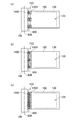
続いて、接続部112の詳細について説明する。図7(a)乃至図7(c)は、第1の実施形態の平面視における表示装置100を示す図である。なお、説明を簡略化するため、図7において、第2格納部118等の構成は省略している。
図6乃至図7(c)に示すように、接続部112は巻き取り部106と表示部102とを接続し、接続部112の回転軸610を中心に巻き取り方向に応じて屈曲するヒンジである。具体的には、接続部112は、巻き取り部106に固定された巻き取り部側接続部112aと、表示部102と接続された表示部側接続部112bと、によって構成される。巻き取り部側接続部112aと表示部側接続部112bとは、回転軸610を中心に屈曲可能なように接続される。
また、接続部112は、表示部102の一辺に離間して配置された複数の接続領域を有するようにしてもよい。具体的には、図7(a)に示すように、接続部112は、表示部102の上下の端部にのみ設けられ、当該端部に設けられた表示部側接続部112bが表示部102と接続されるようにしてもよい。また、図7(b)に示すように、接続部112は、表示部102の左側の一辺に沿って、上端から下端に切れ目ない形状としてもよい。この場合、表示部102の一辺に亘って設けられた表示部側接続部112bと表示部102が接続される。また、図7(c)に示すように、接続部112は、表示部102の左側の一辺に沿って、上端から下端にかけて一部の領域に切れ目を有する形状であってもよい。この場合、表示部側接続部112bは、当該切れ目の設けられていない領域で表示部102と接続される。
続いて、表示装置100が表示部102を巻き取る動作について、図8のフローチャートを用いて説明する。なお、本フローチャートでは、制御部110が記憶部に記憶された巻き取り方向情報に応じて、アクチュエータ108を制御する場合について説明する。
まず、制御部110は、表示部102が全て引き出されたか否かを判定する(S802)。具体的には、制御部110は、巻き取り部106の回転数によって、表示部102が全て引き出されたか否かを判定する。また、制御部110は、図示しないセンサ等により、表示部102が全て引き出されたか否かを判定してもよい。なお、全て引き出された状態とは、図6に示すように、表示部102と巻き取り部106とが接している部分が存在しない状態をいう。
表示部102が全て引き出されたと判定された場合は、制御部110は、記憶部に記憶された巻き取り方向情報を読み出す(S804)。具体的には、例えば、直前の巻き取り方向が第1方向602である場合、記憶部は、第1方向602を表す巻き取り方向情報を記憶している。従って、制御部110は、記憶部から第1方向602を表す巻き取り方向情報を読み出す。
表示部102が全て引き出されていないと判定された場合は、制御部110は、その時点における表示部102の巻き取り方向を維持したまま、アクチュエータ108を制御する。
次に、制御部110は、読み出された巻き取り方向情報が表す巻き取り方向を判定し(S806)、読み出された巻き取り方向情報が第1方向602を表す場合、制御部110は、巻き取り部106が表示部102を第2方向604に巻き取るようにアクチュエータ108を制御する(S808)。一方、読み出された巻き取り方向情報が第2方向604を表す場合、制御部110は、巻き取り部106が表示部102を第1方向602に巻き取るようにアクチュエータ108を制御する(S810)。
次に、検出部606は、巻き取り方向を検出する(S812)。具体的には、巻き取り方向に応じて、接続部112の表示面128側及び裏面側のいずれか一方に配置されたスイッチが押下されることにより、検出部606は、表示部102の巻き取り方向を検出する。記憶部は、検出部606が検出した巻き取り方向を表す巻き取り方向情報を記憶する。
そして、巻き取り部106の動作が終了すると、フローチャートに示した一連の巻き取り動作は終了する(S814)。なお、当該ステップにおいて、表示部102は、全て巻き取られてもよいし、一部が巻き取られてもよい。
なお、検出部606を有しない構成とする場合には、制御部110は、S808の後に、記憶部に記憶された巻き取り方向情報を第1方向602を表す巻き取り方向情報に変更してもよい。また、制御部110は、S810の後に、記憶部に記憶された巻き取り方向情報を第2方向604を表す巻き取り方向情報に変更するようにしてもよい。また、上記フローチャートによれば、制御部110は、第1方向602と第2方向604を交互に切り替えるように制御するが、複数回ごとに巻き取り方向を切り替えるように制御してもよい。
以上のように、第1の実施形態によれば、ローラの巻き取り方向を定期的に変化させることにより、表示部102に巻き癖がつきにくくすることができる。さらに、特に破損の生じやすい接続部112がヒンジで形成されることにより、表示装置100をより破損しにくくすることができる。
なお、接続部112が有する回転軸610の個数は2個以上であってもよい。図9は、第1の実施形態の変形例における表示装置100の断面を示す図である。また、図10(a)乃至図10(c)は、第1の実施形態の変形例において平面視における表示装置100を示す図である。図9及び図10(a)乃至図10(c)に示すように、本変形例における接続部112は、ヒンジであって、2個の回転軸610を有するようにしてもよい。
具体的には、接続部112は、巻き取り部106に固定された巻き取り部側接続部112aと、表示部102と接続された表示部側接続部112bと、巻き取り部側接続部112aと表示部側接続部112bの間に配置された中間接続部112cと、によって構成される。巻き取り部側接続部112aと中間接続部112cとは、回転軸610を中心に屈曲可能なように接続される。また、中間接続部112cと表示部側接続部112bとは、屈曲可能なように接続される。
また、接続部112は、表示部102の一辺に離間して配置された複数の接続領域を有するようにしてもよい。具体的には、図10(a)に示すように、接続部112は、表示部102の上下の端部にのみ設けられ、当該端部に設けられた表示部側接続部112bが表示部102と接続されるようにしてもよい。また、図10(b)に示すように、接続部112は、表示部102の左側の一辺に沿って、上端から下端に切れ目ない形状としてもよい。この場合、表示部102の一辺に亘って設けられた表示部側接続部112bと表示部102が接続される。また、図10(c)に示すように、接続部112は、表示部102の左側の一辺に沿って、上端から下端にかけて一部の領域に切れ目を有する形状であってもよい。この場合、表示部側接続部112bは、当該切れ目の設けられていない領域で表示部102と接続される。
また、図6においては、検出部606は接続部112に設けられていたが、図9に示すように、巻き取り部106に設けられても良い。図6の場合、検出部606は巻き取り部106への接触判定によって巻き取り方向を検出していたが、図9のように、検出部606を巻き取り部106に設ける場合は、検出部606は、表示部102との接触判定によって巻き取り方向が検出される。
本変形例によれば、接続部112の第1方向602及び第2方向604への屈曲性が向上することにより、表示部102と巻き取り部106を接続する接続部112の破損をさらに生じにくくすることができる。
[第2の実施形態]
続いて、第2の実施形態について説明する。第2の実施形態は、接続部112の構造が第1の実施形態と異なる。その他の点については、第1の実施形態と同様であるため、説明を省略する。図11は、第2の実施形態における表示装置100の断面を示す図である。図12は、第2の実施形態の変形例における表示装置100の断面を示す図である。図13(a)及び図13(b)は、第2の実施形態の平面視における表示装置100を示す図である。
続いて、第2の実施形態について説明する。第2の実施形態は、接続部112の構造が第1の実施形態と異なる。その他の点については、第1の実施形態と同様であるため、説明を省略する。図11は、第2の実施形態における表示装置100の断面を示す図である。図12は、第2の実施形態の変形例における表示装置100の断面を示す図である。図13(a)及び図13(b)は、第2の実施形態の平面視における表示装置100を示す図である。
本実施形態における接続部112は、弾性体である。具体的には、例えば、接続部112は、ゴムやばね等の第1方向602及び第2方向604に屈曲可能な弾性体で形成される。図11に示すように、接続部112は、1個のまとまった弾性部材で形成され、巻き取り部106及び表示部102と接続されてもよい。また、接続部112は、複数の弾性部材で構成されてもよい。具体的には、図12に示すように、接続部112は、表示面128に固定された表示面側接続部1202と、表示面128の裏側に、表示面側接続部1202と離間して固定された裏面側接続部1204と、を有していてもよい。
また、接続部112は、表示部102の一辺に離間して配置された複数の接続領域を有するようにしてもよい。具体的には、図13(a)に示すように、接続部112は、表示部102の左側の一辺に沿って、上端から下端に切れ目ない形状としてもよい。この場合、表示部102の一辺に亘って設けられた接続部112と表示部102が接続される。また、図10(b)に示すように、接続部112は、表示部102の左側の一辺に沿って、上端から下端にかけて一部の領域に切れ目を有する形状であってもよい。この場合、接続部112は、当該切れ目の設けられていない領域で表示部102と接続される。
また、図6においては、検出部606は接続部112に設けられていたが、図11、及び図12に示すように、表示部102の表裏に設けられても良い。図6の場合と同様、検出部606は巻き取り部106への接触判定によって巻き取り方向が検出される。
本実施形態においても、接続部112の第1方向602及び第2方向604への屈曲性が向上することにより、表示部102と巻き取り部106を接続する接続部112の破損を生じにくくすることができる。
[第3の実施形態]
続いて、第3の実施形態について説明する。第3の実施形態は、接続部112の構造が第1及び第2の実施形態と異なる。その他の点については、第1の実施形態と同様であるため、説明を省略する。図14は、第3の実施形態における表示装置100の断面を示す図である。図15(a)乃至図15(c)は、第3の実施形態の平面視における表示装置100を示す図である。
続いて、第3の実施形態について説明する。第3の実施形態は、接続部112の構造が第1及び第2の実施形態と異なる。その他の点については、第1の実施形態と同様であるため、説明を省略する。図14は、第3の実施形態における表示装置100の断面を示す図である。図15(a)乃至図15(c)は、第3の実施形態の平面視における表示装置100を示す図である。
本実施形態における接続部112は、巻き取り部側接続部1402と、表示部側接続部1404と、を有する。具体的には、図14に示すように、接続部112は、巻き取り部106と固定されたガイドバーを有する巻き取り部側接続部1402と、ガイドバーが挿通される穴が設けられた表示部側接続部1404と、を有する。ガイドバーは、例えば半環状である。ガイドバーは、半環状の切り欠いた部分が巻き取り部106側になるように巻き取り部106と固定される。穴は、ガイドバーが挿通されるように、ガイドバーの径よりも大きな径でガイドバーに対応する位置に設けられる。
また、接続部112は、表示部102の一辺に離間して配置された複数の接続領域を有するようにしてもよい。具体的には、図15(a)に示すように、接続部112は、表示部102の上下の端部及び中央部にのみ設けられ、当該箇所に設けられた表示部側接続部1404が表示部102と接続されるようにしてもよい。また、図15(b)及び図15(c)に示すように、接続部112は、表示部102の左側の一辺に沿って、上端から下端に切れ目ない形状としてもよい。この場合、表示部102の一辺に亘って設けられた表示部側接続部1404と表示部102が接続される。
また、ガイドバー及び穴の数は、少なくとも2以上であればよい。例えば、図15(a)に示すように、ガイドバー及び穴の数は3個であってもよいし、図15(c)に示すように、ガイドバー及び穴の数は8個であってもよい。
上記のように、本実施形態によれば、接続部は、ルーズリーフの綴じ具のような構造で形成される。これにより、第1及び第2の実施形態と同様に、接続部の第1方向及び第2方向への屈曲性が向上することにより、表示部102と巻き取り部106を接続する接続部の破損を生じにくくすることができる。
本発明の思想の範疇において、当業者であれば、各種の変更例及び修正例に想到し得るものであり、それら変更例及び修正例についても本発明の範囲に属するものと了解される。例えば、前述の各実施形態に対して、当業者が適宜、構成要素の追加、削除若しくは設計変更を行ったもの、又は、工程の追加、省略若しくは条件変更を行ったものも、本発明の要旨を備えている限り、本発明の範囲に含まれる。
Claims (11)
- 画像を表示する表示面を有するシート状の表示部と、
前記表示部を格納する格納部と、
前記格納部に配置され、前記表示面が内側となる第1方向または前記表示面が外側となる第2方向に前記表示部を巻き取る巻き取り部と、
巻き取り方向を前記第1方向または前記第2方向に切り替える切り替え部と、
前記巻き取り部と前記表示部とを接続し、前記巻き取り方向に応じて屈曲する接続部と、
を有することを特徴とする表示装置。 - 前記接続部は、ヒンジであることを特徴とする請求項1に記載の表示装置。
- 前記接続部は、弾性体であることを特徴とする請求項1に記載の表示装置。
- 前記接続部は、前記表示面に固定された表示面側接続部と、前記表示面の裏側に、前記表示面側接続部と離間して固定された裏面側接続部と、を有することを特徴とする請求項3に記載の表示装置。
- 前記接続部は、前記巻き取り部と固定されたガイドバーを有する巻き取り部側接続部と、前記ガイドバーが挿通される穴が設けられた表示部側接続部と、を有することを特徴とする請求項1に記載の表示装置。
- 前記接続部は、前記表示部の一辺に離間して配置された複数の接続領域を有することを特徴とする請求項1に記載の表示装置。
- 前記表示部の巻き取り方向を検出する検出部をさらに有することを特徴とする請求項1に記載の表示装置。
- 前記検出部は、前記接続部が屈曲した状態で前記巻き取り部との接触を検出することを特徴とすることを特徴とする請求項7に記載の表示装置。
- 前記巻き取り方向を記憶する記憶部を有することを特徴とする請求項1に記載の表示装置。
- 前記表示部は、さらに、
前記表示部が前記格納部から全て引き出された場合に、前記巻き取り部が前記記憶部に記憶された巻き取り方向と異なる巻き取り方向に前記表示部を巻き取るように制御する制御部と、
前記制御部の制御によって、前記巻き取り部を第1方向または第2方向に回転させるアクチュエータと、
を有することを特徴とする請求項9に記載の表示装置。 - 前記制御部は、前記第1方向と前記第2方向を交互に切り替えるように制御することを特徴とする請求項10に記載の表示装置。
Applications Claiming Priority (2)
| Application Number | Priority Date | Filing Date | Title |
|---|---|---|---|
| JP2018077499A JP2019184913A (ja) | 2018-04-13 | 2018-04-13 | 表示装置 |
| JP2018-077499 | 2018-04-13 |
Publications (1)
| Publication Number | Publication Date |
|---|---|
| WO2019198294A1 true WO2019198294A1 (ja) | 2019-10-17 |
Family
ID=68162842
Family Applications (1)
| Application Number | Title | Priority Date | Filing Date |
|---|---|---|---|
| PCT/JP2019/001398 Ceased WO2019198294A1 (ja) | 2018-04-13 | 2019-01-18 | 表示装置 |
Country Status (2)
| Country | Link |
|---|---|
| JP (1) | JP2019184913A (ja) |
| WO (1) | WO2019198294A1 (ja) |
Cited By (2)
| Publication number | Priority date | Publication date | Assignee | Title |
|---|---|---|---|---|
| CN111261049A (zh) * | 2020-03-17 | 2020-06-09 | 昆山国显光电有限公司 | 柔性显示装置 |
| CN112396962A (zh) * | 2020-11-16 | 2021-02-23 | 京东方科技集团股份有限公司 | 卷曲显示装置、控制柔性显示屏卷曲的方法及电子设备 |
Families Citing this family (1)
| Publication number | Priority date | Publication date | Assignee | Title |
|---|---|---|---|---|
| KR20230089611A (ko) | 2021-12-13 | 2023-06-21 | 삼성디스플레이 주식회사 | 표시 모듈 구동 장치, 이를 포함하는 표시 장치, 및 이를 이용한 표시 장치 구동 방법 |
Citations (14)
| Publication number | Priority date | Publication date | Assignee | Title |
|---|---|---|---|---|
| JP2003274250A (ja) * | 2002-03-15 | 2003-09-26 | Konica Corp | カメラ |
| JP2005215320A (ja) * | 2004-01-29 | 2005-08-11 | Brother Ind Ltd | 表示装置 |
| JP2005354305A (ja) * | 2004-06-09 | 2005-12-22 | Fuji Photo Film Co Ltd | デジタルカメラ |
| JP2011049411A (ja) * | 2009-08-28 | 2011-03-10 | Fujifilm Corp | 発光装置 |
| JP2011081069A (ja) * | 2009-10-05 | 2011-04-21 | Sony Corp | 表示装置 |
| JP2012113261A (ja) * | 2010-11-26 | 2012-06-14 | Bridgestone Corp | 情報表示システム、情報表示器及び情報表示器の駆動装置 |
| JP2013037330A (ja) * | 2011-08-10 | 2013-02-21 | Samsung Display Co Ltd | 表示装置 |
| WO2013105239A1 (ja) * | 2012-01-11 | 2013-07-18 | 新電元工業株式会社 | モータ回転方向検出方法、および、モータ駆動回路 |
| JP2013154518A (ja) * | 2012-01-27 | 2013-08-15 | Sharp Corp | 表示機能付きバインダー、表示装置、プロセッサ、制御方法および制御プログラム |
| US20150009636A1 (en) * | 2013-07-03 | 2015-01-08 | Samsung Display Co., Ltd. | Flexible display device and method for controlling same |
| US20160034000A1 (en) * | 2014-08-01 | 2016-02-04 | Samsung Display Co., Ltd. | Display device |
| JP2016024460A (ja) * | 2014-07-22 | 2016-02-08 | エルジー ディスプレイ カンパニー リミテッド | ローラブルディスプレイ装置 |
| JP2017116133A (ja) * | 2015-12-22 | 2017-06-29 | 東洋アルミエコープロダクツ株式会社 | 連結具およびパネル構造体 |
| JP2017192203A (ja) * | 2016-04-12 | 2017-10-19 | 株式会社デンソー | モータ制御装置 |
-
2018
- 2018-04-13 JP JP2018077499A patent/JP2019184913A/ja active Pending
-
2019
- 2019-01-18 WO PCT/JP2019/001398 patent/WO2019198294A1/ja not_active Ceased
Patent Citations (14)
| Publication number | Priority date | Publication date | Assignee | Title |
|---|---|---|---|---|
| JP2003274250A (ja) * | 2002-03-15 | 2003-09-26 | Konica Corp | カメラ |
| JP2005215320A (ja) * | 2004-01-29 | 2005-08-11 | Brother Ind Ltd | 表示装置 |
| JP2005354305A (ja) * | 2004-06-09 | 2005-12-22 | Fuji Photo Film Co Ltd | デジタルカメラ |
| JP2011049411A (ja) * | 2009-08-28 | 2011-03-10 | Fujifilm Corp | 発光装置 |
| JP2011081069A (ja) * | 2009-10-05 | 2011-04-21 | Sony Corp | 表示装置 |
| JP2012113261A (ja) * | 2010-11-26 | 2012-06-14 | Bridgestone Corp | 情報表示システム、情報表示器及び情報表示器の駆動装置 |
| JP2013037330A (ja) * | 2011-08-10 | 2013-02-21 | Samsung Display Co Ltd | 表示装置 |
| WO2013105239A1 (ja) * | 2012-01-11 | 2013-07-18 | 新電元工業株式会社 | モータ回転方向検出方法、および、モータ駆動回路 |
| JP2013154518A (ja) * | 2012-01-27 | 2013-08-15 | Sharp Corp | 表示機能付きバインダー、表示装置、プロセッサ、制御方法および制御プログラム |
| US20150009636A1 (en) * | 2013-07-03 | 2015-01-08 | Samsung Display Co., Ltd. | Flexible display device and method for controlling same |
| JP2016024460A (ja) * | 2014-07-22 | 2016-02-08 | エルジー ディスプレイ カンパニー リミテッド | ローラブルディスプレイ装置 |
| US20160034000A1 (en) * | 2014-08-01 | 2016-02-04 | Samsung Display Co., Ltd. | Display device |
| JP2017116133A (ja) * | 2015-12-22 | 2017-06-29 | 東洋アルミエコープロダクツ株式会社 | 連結具およびパネル構造体 |
| JP2017192203A (ja) * | 2016-04-12 | 2017-10-19 | 株式会社デンソー | モータ制御装置 |
Cited By (3)
| Publication number | Priority date | Publication date | Assignee | Title |
|---|---|---|---|---|
| CN111261049A (zh) * | 2020-03-17 | 2020-06-09 | 昆山国显光电有限公司 | 柔性显示装置 |
| CN112396962A (zh) * | 2020-11-16 | 2021-02-23 | 京东方科技集团股份有限公司 | 卷曲显示装置、控制柔性显示屏卷曲的方法及电子设备 |
| CN112396962B (zh) * | 2020-11-16 | 2022-11-01 | 京东方科技集团股份有限公司 | 卷曲显示装置、控制柔性显示屏卷曲的方法及电子设备 |
Also Published As
| Publication number | Publication date |
|---|---|
| JP2019184913A (ja) | 2019-10-24 |
Similar Documents
| Publication | Publication Date | Title |
|---|---|---|
| KR102609502B1 (ko) | 표시 장치 | |
| US11056025B2 (en) | Display device | |
| KR102344282B1 (ko) | 표시장치 | |
| WO2019198294A1 (ja) | 表示装置 | |
| CN107342019A (zh) | 可卷曲显示装置 | |
| US9460644B2 (en) | Flexible display apparatus | |
| US20110084898A1 (en) | Memory shape element for flexible oled display screen | |
| KR102355328B1 (ko) | 플렉서블 표시 장치 | |
| JP2020013163A (ja) | 表示装置 | |
| KR102600966B1 (ko) | 롤러블 표시 장치 | |
| CN114677923A (zh) | 卷曲式显示装置 | |
| KR102891636B1 (ko) | 표시 장치 | |
| JP2007529776A (ja) | 巻くことができる電子パネル装置 | |
| CN107358872A (zh) | 可卷曲柔性显示器 | |
| WO2014142269A1 (ja) | 電子機器 | |
| CN101681074A (zh) | 柔性显示装置中的次显示器集成 | |
| KR102573789B1 (ko) | 플렉서블 표시 장치 | |
| US9547340B2 (en) | Portable terminal having flexible display | |
| JP4807947B2 (ja) | 表示装置 | |
| US20240241398A1 (en) | Active strain management in a layered article | |
| JP7255431B2 (ja) | 表示装置 | |
| JP2009223169A (ja) | 表示装置 | |
| WO2019106966A1 (ja) | 表示装置 | |
| US10222831B2 (en) | Display apparatus | |
| EP3876078B1 (en) | Flexible display device |
Legal Events
| Date | Code | Title | Description |
|---|---|---|---|
| 121 | Ep: the epo has been informed by wipo that ep was designated in this application |
Ref document number: 19785721 Country of ref document: EP Kind code of ref document: A1 |
|
| NENP | Non-entry into the national phase |
Ref country code: DE |
|
| 122 | Ep: pct application non-entry in european phase |
Ref document number: 19785721 Country of ref document: EP Kind code of ref document: A1 |