WO2019196408A1 - 一种嵌入刚性增强元件的光缆护套的成型设备及成型工艺 - Google Patents
一种嵌入刚性增强元件的光缆护套的成型设备及成型工艺 Download PDFInfo
- Publication number
- WO2019196408A1 WO2019196408A1 PCT/CN2018/115357 CN2018115357W WO2019196408A1 WO 2019196408 A1 WO2019196408 A1 WO 2019196408A1 CN 2018115357 W CN2018115357 W CN 2018115357W WO 2019196408 A1 WO2019196408 A1 WO 2019196408A1
- Authority
- WO
- WIPO (PCT)
- Prior art keywords
- cable
- embedded
- core
- vacuum
- cable sheath
- Prior art date
- Legal status (The legal status is an assumption and is not a legal conclusion. Google has not performed a legal analysis and makes no representation as to the accuracy of the status listed.)
- Ceased
Links
Images
Classifications
-
- B—PERFORMING OPERATIONS; TRANSPORTING
- B29—WORKING OF PLASTICS; WORKING OF SUBSTANCES IN A PLASTIC STATE IN GENERAL
- B29C—SHAPING OR JOINING OF PLASTICS; SHAPING OF MATERIAL IN A PLASTIC STATE, NOT OTHERWISE PROVIDED FOR; AFTER-TREATMENT OF THE SHAPED PRODUCTS, e.g. REPAIRING
- B29C48/00—Extrusion moulding, i.e. expressing the moulding material through a die or nozzle which imparts the desired form; Apparatus therefor
- B29C48/15—Extrusion moulding, i.e. expressing the moulding material through a die or nozzle which imparts the desired form; Apparatus therefor incorporating preformed parts or layers, e.g. extrusion moulding around inserts
- B29C48/154—Coating solid articles, i.e. non-hollow articles
-
- B—PERFORMING OPERATIONS; TRANSPORTING
- B29—WORKING OF PLASTICS; WORKING OF SUBSTANCES IN A PLASTIC STATE IN GENERAL
- B29C—SHAPING OR JOINING OF PLASTICS; SHAPING OF MATERIAL IN A PLASTIC STATE, NOT OTHERWISE PROVIDED FOR; AFTER-TREATMENT OF THE SHAPED PRODUCTS, e.g. REPAIRING
- B29C48/00—Extrusion moulding, i.e. expressing the moulding material through a die or nozzle which imparts the desired form; Apparatus therefor
- B29C48/25—Component parts, details or accessories; Auxiliary operations
- B29C48/285—Feeding the extrusion material to the extruder
-
- B—PERFORMING OPERATIONS; TRANSPORTING
- B29—WORKING OF PLASTICS; WORKING OF SUBSTANCES IN A PLASTIC STATE IN GENERAL
- B29C—SHAPING OR JOINING OF PLASTICS; SHAPING OF MATERIAL IN A PLASTIC STATE, NOT OTHERWISE PROVIDED FOR; AFTER-TREATMENT OF THE SHAPED PRODUCTS, e.g. REPAIRING
- B29C48/00—Extrusion moulding, i.e. expressing the moulding material through a die or nozzle which imparts the desired form; Apparatus therefor
- B29C48/25—Component parts, details or accessories; Auxiliary operations
- B29C48/285—Feeding the extrusion material to the extruder
- B29C48/288—Feeding the extrusion material to the extruder in solid form, e.g. powder or granules
- B29C48/2883—Feeding the extrusion material to the extruder in solid form, e.g. powder or granules of preformed parts, e.g. inserts, retaining their shape during the extrusion process
-
- B—PERFORMING OPERATIONS; TRANSPORTING
- B29—WORKING OF PLASTICS; WORKING OF SUBSTANCES IN A PLASTIC STATE IN GENERAL
- B29C—SHAPING OR JOINING OF PLASTICS; SHAPING OF MATERIAL IN A PLASTIC STATE, NOT OTHERWISE PROVIDED FOR; AFTER-TREATMENT OF THE SHAPED PRODUCTS, e.g. REPAIRING
- B29C48/00—Extrusion moulding, i.e. expressing the moulding material through a die or nozzle which imparts the desired form; Apparatus therefor
- B29C48/25—Component parts, details or accessories; Auxiliary operations
- B29C48/30—Extrusion nozzles or dies
-
- B—PERFORMING OPERATIONS; TRANSPORTING
- B29—WORKING OF PLASTICS; WORKING OF SUBSTANCES IN A PLASTIC STATE IN GENERAL
- B29C—SHAPING OR JOINING OF PLASTICS; SHAPING OF MATERIAL IN A PLASTIC STATE, NOT OTHERWISE PROVIDED FOR; AFTER-TREATMENT OF THE SHAPED PRODUCTS, e.g. REPAIRING
- B29C48/00—Extrusion moulding, i.e. expressing the moulding material through a die or nozzle which imparts the desired form; Apparatus therefor
- B29C48/25—Component parts, details or accessories; Auxiliary operations
- B29C48/30—Extrusion nozzles or dies
- B29C48/32—Extrusion nozzles or dies with annular openings, e.g. for forming tubular articles
-
- B—PERFORMING OPERATIONS; TRANSPORTING
- B29—WORKING OF PLASTICS; WORKING OF SUBSTANCES IN A PLASTIC STATE IN GENERAL
- B29C—SHAPING OR JOINING OF PLASTICS; SHAPING OF MATERIAL IN A PLASTIC STATE, NOT OTHERWISE PROVIDED FOR; AFTER-TREATMENT OF THE SHAPED PRODUCTS, e.g. REPAIRING
- B29C48/00—Extrusion moulding, i.e. expressing the moulding material through a die or nozzle which imparts the desired form; Apparatus therefor
- B29C48/25—Component parts, details or accessories; Auxiliary operations
- B29C48/78—Thermal treatment of the extrusion moulding material or of preformed parts or layers, e.g. by heating or cooling
- B29C48/79—Thermal treatment of the extrusion moulding material or of preformed parts or layers, e.g. by heating or cooling of preformed parts or layers
-
- B—PERFORMING OPERATIONS; TRANSPORTING
- B29—WORKING OF PLASTICS; WORKING OF SUBSTANCES IN A PLASTIC STATE IN GENERAL
- B29C—SHAPING OR JOINING OF PLASTICS; SHAPING OF MATERIAL IN A PLASTIC STATE, NOT OTHERWISE PROVIDED FOR; AFTER-TREATMENT OF THE SHAPED PRODUCTS, e.g. REPAIRING
- B29C48/00—Extrusion moulding, i.e. expressing the moulding material through a die or nozzle which imparts the desired form; Apparatus therefor
- B29C48/25—Component parts, details or accessories; Auxiliary operations
- B29C48/88—Thermal treatment of the stream of extruded material, e.g. cooling
-
- B—PERFORMING OPERATIONS; TRANSPORTING
- B29—WORKING OF PLASTICS; WORKING OF SUBSTANCES IN A PLASTIC STATE IN GENERAL
- B29C—SHAPING OR JOINING OF PLASTICS; SHAPING OF MATERIAL IN A PLASTIC STATE, NOT OTHERWISE PROVIDED FOR; AFTER-TREATMENT OF THE SHAPED PRODUCTS, e.g. REPAIRING
- B29C48/00—Extrusion moulding, i.e. expressing the moulding material through a die or nozzle which imparts the desired form; Apparatus therefor
- B29C48/25—Component parts, details or accessories; Auxiliary operations
- B29C48/88—Thermal treatment of the stream of extruded material, e.g. cooling
- B29C48/90—Thermal treatment of the stream of extruded material, e.g. cooling with calibration or sizing, i.e. combined with fixing or setting of the final dimensions of the extruded article
-
- B—PERFORMING OPERATIONS; TRANSPORTING
- B29—WORKING OF PLASTICS; WORKING OF SUBSTANCES IN A PLASTIC STATE IN GENERAL
- B29C—SHAPING OR JOINING OF PLASTICS; SHAPING OF MATERIAL IN A PLASTIC STATE, NOT OTHERWISE PROVIDED FOR; AFTER-TREATMENT OF THE SHAPED PRODUCTS, e.g. REPAIRING
- B29C48/00—Extrusion moulding, i.e. expressing the moulding material through a die or nozzle which imparts the desired form; Apparatus therefor
- B29C48/25—Component parts, details or accessories; Auxiliary operations
- B29C48/88—Thermal treatment of the stream of extruded material, e.g. cooling
- B29C48/911—Cooling
-
- B—PERFORMING OPERATIONS; TRANSPORTING
- B29—WORKING OF PLASTICS; WORKING OF SUBSTANCES IN A PLASTIC STATE IN GENERAL
- B29C—SHAPING OR JOINING OF PLASTICS; SHAPING OF MATERIAL IN A PLASTIC STATE, NOT OTHERWISE PROVIDED FOR; AFTER-TREATMENT OF THE SHAPED PRODUCTS, e.g. REPAIRING
- B29C63/00—Lining or sheathing, i.e. applying preformed layers or sheathings of plastics; Apparatus therefor
-
- G—PHYSICS
- G02—OPTICS
- G02B—OPTICAL ELEMENTS, SYSTEMS OR APPARATUS
- G02B6/00—Light guides; Structural details of arrangements comprising light guides and other optical elements, e.g. couplings
- G02B6/44—Mechanical structures for providing tensile strength and external protection for fibres, e.g. optical transmission cables
-
- B—PERFORMING OPERATIONS; TRANSPORTING
- B29—WORKING OF PLASTICS; WORKING OF SUBSTANCES IN A PLASTIC STATE IN GENERAL
- B29L—INDEXING SCHEME ASSOCIATED WITH SUBCLASS B29C, RELATING TO PARTICULAR ARTICLES
- B29L2011/00—Optical elements, e.g. lenses, prisms
- B29L2011/0075—Light guides, optical cables
Definitions
- the present invention relates to the field of optical cable manufacturing, and in particular to a molding apparatus and a molding process for a cable jacket embedded in a rigid reinforcing component.
- Optical cables are manufactured to meet optical, mechanical, or environmental performance specifications. They are communication cable assemblies that utilize one or more optical fibers placed in a sheath as a transmission medium and can be used individually or in groups.
- the optical cable is mainly composed of optical fiber and plastic protective sleeve and plastic outer skin. A certain number of optical fibers form a cable core in a certain way, and are sheathed with outer sheath, and some are also covered with an outer protective layer for realizing optical signal transmission. Communication line.
- GFRP also known as GRP or FRP, Chinese name glass fiber reinforced plastic, commonly known as FRP, is an organic non-metallic and inorganic non-metal composite plastic matrix composite
- FRP Chinese name glass fiber reinforced plastic
- steel wire and other rigid reinforcement elements embedded in the cable jacket is A novel fiber optic cable design.
- This design has many advantages: Firstly, because the rigid reinforcing element plays a supporting role on the cable sheath, it resists the shrinkage during the forming process of the sheath and after forming, which makes the cable structure more stable and greatly improves the attenuation temperature characteristics of the cable. . Secondly, the rigid reinforcing element makes the whole cable have moderate rigidity and elasticity, which is beneficial to the construction environment such as air blowing and pipeline. Again, the rigid reinforcing element can partially or completely replace the conventionally used aramid, which greatly reduces the cost of the cable as a whole.
- the key to achieving this cable design is the sheath forming equipment and process.
- molten plastic is pushed into a molding die composed of a core and a mold cover to form a tubular shape, which is cooled by circulating water to be finalized.
- the conventional molding method due to the rigidity of the component, causes the sheath to be stretched, shrunk, and cooled unevenly in all directions during the molding process, resulting in the ovality of the cable sheath exceeding the standard or even being impossible.
- the embedded reinforcing element must increase the wall thickness of the cable, which will inevitably delay the cooling process of the cable jacket, resulting in prolonged heating time of the cable core, greatly increasing the risk of adhesion between the cable core and the inner wall of the sheath.
- the object of the present invention is to overcome the deficiencies of the above-mentioned background art, and to provide a molding apparatus and a molding process for a cable sheath embedded with a rigid reinforcing member, which can precisely control the size of the cable sheath, and the core and the inner wall of the sheath are not easily adhered.
- the invention provides a molding apparatus for a cable sheath embedded with a rigid reinforcing component, which comprises:
- An extruder comprising a head for processing a rigid reinforcing element
- a core guiding device internally provided with a core passage, the core passage communicating with a die of the extruder, and a cooling device disposed around the core passage;
- the vacuum sizing sleeve is internally provided with a sizing passage for cable molding, the sizing passage is connected with the discharge port of the extruder, and a vacuum interlayer is disposed outside the sizing passage.
- the core guiding device is a three-way pipe
- the three-way pipe includes a main pipe, and a branch pipe located perpendicular to the main pipe on the main pipe side and communicating therewith, the cable core passage running through the main pipe .
- the structure is simple and the cost is low, and the core passage passes through the main pipe into the extruder head, so that the cable core can directly merge with the formed cable sheath.
- the cooling device is connected to the main pipe by the branch pipe, is disposed around the cable passage, and is led out by the branch pipe. It facilitates the installation of the cooling device and facilitates the cooling device to surround the cable channel, allowing complete cooling of the cable core in all directions.
- the cooling device is a condensation tube with a condensing agent inside. Cooling by condensation method is easy to realize and low in cost; the internal environment of the tee can be set to a negative pressure state relative to the atmosphere, and the core can be processed into the extruder along with the condensed air in the tee. In the cable jacket, the cold air accelerates the cooling of the inner wall of the cable jacket and the core, greatly reducing the risk of adhesion between the two.
- the sizing passage extends through the entire vacuum sizing sleeve, and the inner diameter of the sizing passage is equal to the outer diameter of the cable jacket.
- the plastic melted body embedded in the extrusion machine and embedded with the rigid reinforcing element is irregularly tubular, and is drawn into an approximate vacuum state after being introduced into the sizing passage of the inner diameter and the outer diameter of the cable sheath. That is, the outer wall of the cable sheath is in an environment of approximately vacuum, and the inside of the cable sheath is connected to the atmosphere in the sizing passage, and the internal pressure of the cable sheath is higher than the external pressure, so that the outer surface thereof is closely attached to the sizing of the outer wall thereof. On the inner wall of the channel, it is possible to form a rounded tube of a regular shape of a desired size.
- the vacuum sizing sleeve further includes a first cooling zone and a second cooling zone disposed outside the sizing channel, and the first cooling zone and the second cooling zone are respectively disposed at the The left and right sides of the vacuum sandwich are described.
- the cable sheath passes through the first cooling zone, the vacuum interlayer and the second cooling zone in sequence, and undergoes the processes of cooling, forming and re-cooling, and has good forming effect and high efficiency.
- the vacuum sizing sleeve sidewall is provided with a vacuuming port for performing a vacuuming operation on the vacuum interlayer.
- the vacuum sandwich outside the internal sizing passage of the vacuum sizing sleeve is evacuated through a vacuum port.
- the side wall of the vacuum sizing sleeve is provided with a water inlet respectively communicating with the first cooling zone and the second cooling zone, and the side wall of the other side of the vacuum sizing sleeve corresponds to each
- Each of the water inlets is provided with a water outlet. Water is introduced through the water inlet and water is discharged from the water outlet, and the outer wall of the sizing channel can be water-cooled to accelerate the rounding of the cable sheath and improve the molding efficiency.
- the invention also provides a molding process for a cable jacket embedded with a rigid reinforcing element, comprising the following steps:
- step S2 the cable core is cooled before the cable core is introduced into the cable jacket.
- step S3 the outer portion of the cable sheath is cooled during the process of forming the cable sheath of the embedded optical cable into a round tubular shape.
- a molding apparatus for a cable jacket embedded with a rigid reinforcing member which extrudes a plastic melt embedded in a rigid reinforcing member by an extruder to form an irregular tubular shape, and then enters a vacuum sizing sleeve through the optical cable.
- the vacuum interlayer outside the sheath creates a pressure difference between the inside and the outside of the cable sheath, so that the cable sheath is closely attached to the outer wall of the sizing passage, and is formed into a round tubular shape of a desired size to realize the size of the cable sheath.
- the cold air can accelerate the cooling between the cable sheath and the core to avoid adhesion
- the cable sheath has good forming effect, high quality and high processing efficiency.
- a molding apparatus for a cable sheath embedded with a rigid reinforcing member of the present invention uses a tee pipe as a core guiding device, has a simple structure and low cost, and is convenient for setting a cooling device and surrounding the cable passage, and the cable
- the cooling effect of the core is good; the cooling by the condensing method is easy to realize, the cost is low, and the risk of adhesion between the cable core and the cable sheath is reduced.
- a molding apparatus for a cable sheath embedded with a rigid reinforcing member of the present invention which adopts a vacuum sizing sleeve, and is provided with a vacuum port, a water inlet and a water outlet on the outer wall thereof, since the vacuum sandwich is drawn into an approximate vacuum
- the state that is, the outer wall of the cable sheath is in an environment of approximate vacuum, and the inside of the cable sheath is connected to the atmosphere in the sizing passage, and the internal pressure of the cable sheath is higher than the external pressure, which is convenient for forming the cable jacket, and can be sized
- the outer wall of the channel is water-cooled to accelerate the rounding of the cable sheath and improve the molding efficiency.
- a molding process of a cable jacket embedded with a rigid reinforcing member of the present invention which realizes precise control of the size of the cable sheath embedded in the rigid reinforcing member by means of a vacuum sizing sleeve; by adding inside the core guiding device
- the cooling device compensates for the problem of internal cooling of the cable, which greatly reduces the risk of the cable core sticking to the inner wall of the cable jacket.
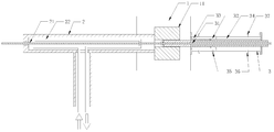
- FIG. 1 is a schematic view showing the structure of a molding apparatus for a cable sheath embedded with a rigid reinforcing member according to an embodiment of the present invention.
- an embodiment of the present invention provides a molding apparatus for a cable jacket embedded with a rigid reinforcing component, including:
- An extruder 1 comprising a handpiece 11 for processing a rigid reinforcing element
- the core guiding device 2 is internally provided with a core channel 21, the core channel 21 is in communication with the die of the extruder 1, and a cooling device 22 is disposed around the core channel 21;
- the vacuum sizing sleeve 3 is internally provided with a sizing passage 31 for cable molding, the sizing passage 31 is in communication with the discharge opening of the extruder 1, and a vacuum interlayer 32 is disposed outside the sizing passage 31.
- the invention extrudes the plastic melt embedded in the rigid reinforcing element by the extruder 1 to form an irregular tubular shape, and then enters the vacuum sizing sleeve 3, and manufactures the inner and outer portions of the cable sheath through the vacuum interlayer 32 outside the cable sheath.
- the pressure difference causes the cable sheath to be closely attached to the outer wall of the sizing passage 31, and is formed into a round tubular shape of a desired size to achieve fine control of the size of the cable sheath; and at the same time, through the inside of the cable guiding device 2
- the cooling device 22 cools the cable core and guides it to the center of the cable jacket.
- the cold air accelerates the cooling between the cable jacket and the cable core, avoids the adhesion between the two cables, compensates for the internal cooling problem of the cable, and forms the cable jacket. Good effect, high quality and high processing efficiency.
- the core guiding device 2 is a tee pipe
- the tee pipe includes a main pipe, and a branch pipe located perpendicular to the main pipe on the main pipe side and communicating therewith, the cable core passage 21 runs through the main pipe; the structure of the three-way pipe is simple and the cost is low, and the core channel 21 is inserted into the extruder head 11 through the main pipe, so that the cable core can directly merge with the formed cable sheath.
- the cooling device 22 is introduced into the main pipe by the branch pipe, is disposed around the core passage 21, and is opened by the branch pipe; facilitates installation of the cooling device 22, and facilitates the cooling device 22 Surrounding the core channel 21, the cable core can be completely cooled in all directions.
- the cooling device 22 is a condensation tube with a condensing agent inside; the cooling method is convenient to realize, and the cost is low; the internal environment of the tee can be set to a negative pressure state relative to the atmosphere.
- the cable core can enter the cable sheath processed by the extruder 1 along with the condensed air in the tee tube, and the cold air accelerates the cooling of the inner wall of the cable sheath and the core of the cable, which greatly reduces the The risk of adhesion.
- the invention adopts a three-way pipe as the core guiding device 2, has a simple structure and low cost, is convenient to install the cooling device 22 and surrounds the core channel 21, and has good cooling effect on the cable core; cooling by using condensation method is easy to realize, and the cost is low. Low, reducing the risk of adhesion between the cable core and the cable jacket.
- the sizing passage 31 extends through the entire vacuum sizing sleeve 3, and the inner diameter of the sizing passage 31 is equal to the outer diameter of the cable sheath; the embedded rigid reinforcing member processed by the extruder 1
- the plastic melted body is irregularly tubular, and after being introduced into the sizing passage 31 having the inner diameter and the outer diameter of the cable sheath, the vacuum jacket is drawn into an approximate vacuum state, that is, the outer wall of the cable sheath is in an approximately vacuum environment.
- the inside of the cable sheath is connected to the atmosphere in the sizing passage 31, and the internal pressure of the cable sheath is higher than the external pressure, so that the outer surface thereof is closely attached to the inner wall of the sizing passage 31 of the outer wall thereof, so that it can be formed into a A rounded tube that requires a regular shape of size.
- the vacuum sizing sleeve 3 further includes a first cooling zone 33 and a second cooling zone 34 disposed outside the sizing passage 31, the first cooling zone 33, the second Cooling zones 34 are respectively disposed on the left and right sides of the vacuum interlayer 32; during the molding process of the cable sheathing sleeve 3, the cable jacket passes through the first cooling zone 33, the vacuum interlayer 32, and the second cooling zone 34, and undergoes The process of cooling, molding, and re-cooling has good molding effect and high efficiency.
- the side wall of the vacuum sizing sleeve 3 is provided with a vacuuming port 35 for performing a vacuuming operation on the vacuum interlayer 32; and the inside of the vacuum sizing sleeve 3 is provided through the vacuuming port 35
- the vacuum sandwich 32 outside the sizing passage 31 performs a vacuuming operation.
- the side wall of the vacuum sizing sleeve 3 is provided with a water inlet 36 respectively communicating with the first cooling zone 33 and the second cooling zone 34, and the other side of the vacuum sizing sleeve 3
- a water outlet 37 is disposed on each side wall corresponding to each of the water inlets 36; water is introduced through the water inlet 36, and the water outlet 37 is effluent, and the outer wall of the sizing passage 31 can be water-cooled to accelerate the rounding of the cable sheath. To improve the efficiency of its molding.
- the invention adopts the vacuum sizing sleeve 3, and the vacuum wall 35, the water inlet 36 and the water outlet 37 are arranged on the outer wall thereof, because the vacuum interlayer 32 is drawn into an approximate vacuum state, that is, the outer wall of the cable sheath is in an approximate vacuum environment.
- the inside of the cable sheath is connected to the atmosphere in the sizing passage 31, and the internal pressure of the cable sheath is higher than the external pressure, which is convenient for forming the cable jacket, and can simultaneously perform water cooling on the outer wall of the sizing passage 31 to accelerate the sheath of the cable. Round forming to improve the efficiency of molding.
- Embodiments of the present invention also provide a molding process for a cable jacket embedded with a rigid reinforcing component, including the following steps:
- the cable sheath of the embedded optical cable is formed into a round tubular shape by the molding device 3.
- the invention realizes the preliminary forming of the cable sheath, the introduction of the cable core, and finally the rounding of the cable sheath into the required diameter by the forming device.
- the molding effect is good, the shape and diameter of the cable sheath meet the requirements, the processing quality is good, and the efficiency is high.
- step S2 the core is cooled before the cable core is introduced into the cable jacket; the cold air accelerates the cooling of the inner wall of the cable jacket and the core, greatly reducing the The risk of adhesions.
- step S3 in the process of forming the cable sheath of the embedded optical cable into a round tubular shape, the outer portion of the cable sheath is cooled; the outer wall of the sizing sleeve 31 may be water-cooled. Accelerate the rounding of the cable jacket to improve the efficiency of its forming.
- the molding process of the cable sheath embedded with the rigid reinforcing component of the present invention has the advantages that the size of the cable sheath embedded in the rigid reinforcing component is accurate by the device of the vacuum sizing sleeve 3. Control, avoiding stretching, shrinkage and uneven cooling in all directions, resulting in excessive ellipticality of the cable sheath or even failure to form; by adding cooling device 22 inside the core guiding device 2, making up for the internal cooling of the cable, greatly reducing the cable The risk of the core sticking to the inner wall of the cable jacket.
Landscapes
- Engineering & Computer Science (AREA)
- Mechanical Engineering (AREA)
- Physics & Mathematics (AREA)
- Thermal Sciences (AREA)
- Manufacturing & Machinery (AREA)
- General Physics & Mathematics (AREA)
- Optics & Photonics (AREA)
- Extrusion Moulding Of Plastics Or The Like (AREA)
Abstract
一种嵌入刚性增强元件的光缆护套的成型设备及成型工艺。该成型设备包括:挤塑机(1),其包括用于加工嵌入刚性增强元件的机头(11);缆芯导向装置(2),其内部设置有缆芯通道(21),所述缆芯通道(21)与挤塑机(1)的模口相连通,缆芯通道(21)四周设置有冷却装置(22);真空定径套(3),其内部设置有用于光缆成型的定径通道(31),所述定径通道(31)与挤塑机(1)的出料口相连通,定径通道(31)外部设置有真空夹层(32)。通过该成型装置实现了嵌入刚性增强元件的光缆护套尺寸的精确控制,通过在缆芯导向装置内部增加冷却装置,弥补光缆内部冷却的问题,降低了缆芯与光缆护套内壁粘连的风险。
Description
本发明涉及光缆制造领域,具体是涉及一种嵌入刚性增强元件的光缆护套的成型设备及成型工艺。
光缆是为了满足光学、机械或环境的性能规范而制造的,它是利用置于包覆护套中的一根或多根光纤作为传输媒质并可以单独或成组使用的通信线缆组件。光缆主要是由光导纤维和塑料保护套管及塑料外皮构成,一定数量的光纤按照一定方式组成缆心,外包有护套,有的还包覆外护层,用以实现光信号传输的一种通信线路。
将GFRP(也叫GRP或FRP,中文名玻璃纤维增强塑料,俗称玻璃钢,是一种有机非金属跟无机非金属复合的塑料基复合材料)、钢丝等刚性增强元件嵌入到光缆护套内,是一种新颖的光缆设计方案。这种设计有诸多优势:首先,由于刚性增强元件对光缆护套起到了支撑作用,抵制了护套成型过程中以及成型后的收缩,使得光缆结构更加稳定,极大提升了光缆的衰减温度特性。其次,刚性增强元件使得整个光缆具备适度的刚性和弹性,有利于气吹、管道等施工环境作业。再次,刚性增强元件能够部分或全部替代传统使用的芳纶,整体上大大降低了光缆成本。
实现这一光缆设计的关键在于护套成型设备及工艺。使用常规的护套成型设备的成型过程中,将熔融塑料推挤到由模芯和模盖组成的成型模具中,形成管状,再经循环水冷却,最终定型。然而在有刚性 元件嵌入护套时,这种传统成型方式,由于元件的刚性作用,使得护套在成型过程中,各个方向拉伸、收缩、冷却不均匀,造成光缆护套椭圆度超标甚至无法成型;另一方面,嵌入增强元件必须增加光缆壁厚,这样必然会延缓光缆护套的冷却过程,导致缆芯受热时间延长,大大增加了缆芯与护套内壁粘连的风险。
发明内容
本发明的目的是为了克服上述背景技术的不足,提供一种可精确控制光缆护套尺寸,缆芯与护套内壁不易粘连的一种嵌入刚性增强元件的光缆护套的成型设备及成型工艺。
本发明提供一种嵌入刚性增强元件的光缆护套的成型设备,其特征在于,包括:
挤塑机,其包括用于加工嵌入刚性增强元件的机头;
缆芯导向装置,其内部设置有缆芯通道,所述缆芯通道与挤塑机的模口相连通,缆芯通道四周设置有冷却装置;
真空定径套,其内部设置有用于光缆成型的定径通道,所述定径通道与挤塑机的出料口相连通,定径通道外部设置有真空夹层。
在上述技术方案的基础上,所述缆芯导向装置为三通管,所述三通管包括主管,及位于所述主管一侧垂直于主管并与其连通的支管,所述缆芯通道贯穿主管。结构简单,成本低,缆芯通道贯穿主管通入到挤塑机机头中,便于缆芯直接与成型后的光缆护套汇合。
在上述技术方案的基础上,所述冷却装置由所述支管通入主管,环绕所述缆芯通道设置,并由支管通出。便于冷却装置的安装设置,并且方便冷却装置环绕缆芯通道,可对缆芯全方位实现彻底的冷却。
在上述技术方案的基础上,所述冷却装置为内部通有冷凝剂的冷凝管。采用冷凝方式冷却,易实现,成本低;可将三通管内部环境 设置为相对大气的负压状态,缆芯即可随着三通管内的被冷凝后的空气一起进入到挤塑机加工出的光缆护套中,冷空气加速了光缆护套内壁和缆芯的冷却,极大地降低了二者粘连的风险。
在上述技术方案的基础上,所述定径通道贯穿整个真空定径套,定径通道的内径等于光缆护套的外径。由挤塑机中加工出的嵌入刚性增强元件的塑料融通体为不规则管状,在通入到内径等与光缆护套外径的定径通道中后,由于真空夹层内被抽成近似真空状态,即光缆护套外壁处于近似真空的环境,而光缆护套内部在定径通道内与大气相通,光缆护套的内压高于外压,因而其外表面会紧贴在其外壁的定径通道内壁上,即可成型为所需大小的形状规则的圆整的管状。
在上述技术方案的基础上,所述真空定径套还包括设置于所述定径通道外部的第一冷却区、第二冷却区,所述第一冷却区、第二冷却区分别设置在所述真空夹层的左右两侧。光缆护套在真空定径套内的成型过程中,依次经过第一冷却区、真空夹层、第二冷却区,经历了冷却、成型、再次冷却的过程,成型效果好,效率高。
在上述技术方案的基础上,所述真空定径套侧壁上设置有用于对所述真空夹层进行抽真空操作的抽真空口。通过抽真空口对真空定径套内部定径通道之外的真空夹层进行抽真空操作。
在上述技术方案的基础上,所述真空定径套侧壁上设置有分别与所述第一冷却区、第二冷却区连通的进水口,真空定径套另一侧的侧壁上对应每个所述进水口位置均设置有出水口。通过进水口进水,出水口出水,可对定径通道外壁进行水冷,加速光缆护套的圆整成型,提高其成型的效率。
本发明还提供一种嵌入刚性增强元件的光缆护套的成型工艺,包括以下步骤:
S1、通过挤塑机将嵌入性增强元件的塑料熔融体加工成不规则管状的光缆护套;
S2、通过缆芯导向装置将缆芯导入到光缆护套中;
S3、通过成型装置将内嵌光缆的光缆护套成型为圆整的管状。
在上述技术方案的基础上,在步骤S2中,在将缆芯导入光缆护套前,对缆芯进行冷却。
在上述技术方案的基础上,在步骤S3中,在将内嵌光缆的光缆护套成型为圆整的管状过程中,对光缆护套外部进行冷却。
与现有技术相比,本发明的优点如下:
(1)本发明一种嵌入刚性增强元件的光缆护套的成型设备,通过挤塑机将嵌入刚性增强元件的塑料熔融体挤出形成不规则的管状,随后进入真空定径套中,通过光缆护套外部的真空夹层,对光缆护套内外部制造压力差,使光缆护套紧贴在定径通道外壁,成型为所需大小的形状规则的圆整的管状,实现对光缆护套尺寸的精控制;同时,通过缆芯导向装置内部的冷却装置,将缆芯进行冷却后导向到光缆护套的中心处,冷空气可加速光缆护套与缆芯之间的冷却,避免二者发生粘连,弥补光缆内部冷却问题,光缆护套成型效果好,质量高,加工效率高。
(2)本发明的一种嵌入刚性增强元件的光缆护套的成型设备,采用三通管作为缆芯导向装置,结构简单,成本低,便于设置冷却装置并使其环绕缆芯通道,对缆芯的冷却效果好;采用冷凝方式冷却,易实现,成本低,降低缆芯与光缆护套的粘连风险。
(3)本发明的一种嵌入刚性增强元件的光缆护套的成型设备,采用真空定径套,并在其外壁设置抽真空口、进水口和出水口,由于真空夹层内被抽成近似真空状态,即光缆护套外壁处于近似真空的环 境,而光缆护套内部在定径通道内与大气相通,光缆护套的内压高于外压,便于光缆护套的成型,同时可对定径通道外壁进行水冷,加速光缆护套的圆整成型,提高其成型的效率。
(4)本发明的一种嵌入刚性增强元件的光缆护套的成型工艺,通过真空定径套这一装置实现嵌入刚性增强元件的光缆护套尺寸的精确控制;通过在缆芯导向装置内部增加冷却装置,弥补光缆内部冷却的问题,大大降低了缆芯与光缆护套内壁粘连的风险。
图1是本发明实施例的一种嵌入刚性增强元件的光缆护套的成型设备的结构示意图。
附图标记:1—挤塑机,11—机头,2—缆芯导向装置,21—缆芯通道,22—冷却装置,3—真空定径套,31—定径通道,32—真空夹层,33—第一冷却区,34—第二冷却区,35—抽真空口,36—进水口,37—出水口。
下面结合附图及具体实施例对本发明作进一步的详细描述。
参见图1所示,本发明实施例提供一种嵌入刚性增强元件的光缆护套的成型设备,包括:
挤塑机1,其包括用于加工嵌入刚性增强元件的机头11;
缆芯导向装置2,其内部设置有缆芯通道21,所述缆芯通道21与挤塑机1的模口相连通,缆芯通道21四周设置有冷却装置22;
真空定径套3,其内部设置有用于光缆成型的定径通道31,所述定径通道31与挤塑机1的出料口相连通,定径通道31外部设置有真空夹层32。
本发明通过挤塑机1将嵌入刚性增强元件的塑料熔融体挤出形成不规则的管状,随后进入真空定径套3中,通过光缆护套外部的真空夹层32,对光缆护套内外部制造压力差,使光缆护套紧贴在定径通道31外壁,成型为所需大小的形状规则的圆整的管状,实现对光缆护套尺寸的精控制;同时,通过缆芯导向装置2内部的冷却装置22,将缆芯进行冷却后导向到光缆护套的中心处,冷空气可加速光缆护套与缆芯之间的冷却,避免二者发生粘连,弥补光缆内部冷却问题,光缆护套成型效果好,质量高,加工效率高。
本发明的第二个实施例,所述缆芯导向装置2为三通管,所述三通管包括主管,及位于所述主管一侧垂直于主管并与其连通的支管,所述缆芯通道21贯穿主管;采用三通管结构简单,成本低,缆芯通道21贯穿主管通入到挤塑机机头11中,便于缆芯直接与成型后的光缆护套汇合。
本发明的第三个实施例,所述冷却装置22由所述支管通入主管,环绕所述缆芯通道21设置,并由支管通出;便于冷却装置22的安装设置,并且方便冷却装置22环绕缆芯通道21,可对缆芯全方位实现彻底的冷却。
在本实施例中,优选的,所述冷却装置22为内部通有冷凝剂的冷凝管;采用冷凝方式冷却,易实现,成本低;可将三通管内部环境设置为相对大气的负压状态,缆芯即可随着三通管内的被冷凝后的空气一起进入到挤塑机1加工出的光缆护套中,冷空气加速了光缆护套内壁和缆芯的冷却,极大地降低了二者粘连的风险。
本发明采用三通管作为缆芯导向装置2,结构简单,成本低,便于设置冷却装置22并使其环绕缆芯通道21,对缆芯的冷却效果好;采用冷凝方式冷却,易实现,成本低,降低缆芯与光缆护套的粘连风 险。
本发明的第四个实施例,所述定径通道31贯穿整个真空定径套3,定径通道31的内径等于光缆护套的外径;由挤塑机1中加工出的嵌入刚性增强元件的塑料融通体为不规则管状,在通入到内径等与光缆护套外径的定径通道31中后,由于真空夹层内被抽成近似真空状态,即光缆护套外壁处于近似真空的环境,而光缆护套内部在定径通道31内与大气相通,光缆护套的内压高于外压,因而其外表面会紧贴在其外壁的定径通道31内壁上,即可成型为所需大小的形状规则的圆整的管状。
本发明的第五个实施例,所述真空定径套3还包括设置于所述定径通道31外部的第一冷却区33、第二冷却区34,所述第一冷却区33、第二冷却区34分别设置在所述真空夹层32的左右两侧;光缆护套在真空定径套3内的成型过程中,依次经过第一冷却区33、真空夹层32、第二冷却区34,经历了冷却、成型、再次冷却的过程,成型效果好,效率高。
在本实施例中,优选的,所述真空定径套3侧壁上设置有用于对所述真空夹层32进行抽真空操作的抽真空口35;通过抽真空口35对真空定径套3内部定径通道31之外的真空夹层32进行抽真空操作。
本发明的第六个实施例,所述真空定径套3侧壁上设置有分别与所述第一冷却区33、第二冷却区34连通的进水口36,真空定径套3另一侧的侧壁上对应每个所述进水口36位置均设置有出水口37;通过进水口36进水,出水口37出水,可对定径通道31外壁进行水冷,加速光缆护套的圆整成型,提高其成型的效率。
本发明采用采用真空定径套3,并在其外壁设置抽真空口35、进 水口36和出水口37,由于真空夹层32内被抽成近似真空状态,即光缆护套外壁处于近似真空的环境,而光缆护套内部在定径通道31内与大气相通,光缆护套的内压高于外压,便于光缆护套的成型,同时可对定径通道31外壁进行水冷,加速光缆护套的圆整成型,提高其成型的效率。
本发明实施例还提供一种嵌入刚性增强元件的光缆护套的成型工艺,包括以下步骤:
S1、通过挤塑机1将嵌入性增强元件的塑料熔融体加工成不规则管状的光缆护套;
S2、通过缆芯导向装置2将缆芯导入到光缆护套中;
S3、通过成型装置3将内嵌光缆的光缆护套成型为圆整的管状。
本发明通过以上三个步骤,分别实现光缆护套初步成型,缆芯的导入,最后利用成型装置对光缆护套进行圆整成型为所需的直径。相比传统加工工艺,成型效果好,光缆护套的形状与直径符合要求,加工质量好,效率高。
在本实施例中,优选的,在步骤S2中,在将缆芯导入光缆护套前,对缆芯进行冷却;冷空气可加速光缆护套内壁和缆芯的冷却,极大地降低了二者粘连的风险。
在本实施例中,优选的,在步骤S3中,在将内嵌光缆的光缆护套成型为圆整的管状过程中,对光缆护套外部进行冷却;可对定径套31外壁进行水冷,加速光缆护套的圆整成型,提高其成型的效率。
与现有的工艺技术相比,本发明的一种嵌入刚性增强元件的光缆护套的成型工艺的优点在于:通过真空定径套3这一装置实现嵌入刚性增强元件的光缆护套尺寸的精确控制,避免其各个方向拉伸、收缩、冷却不均匀,造成光缆护套椭圆度超标甚至无法成型;通过在缆芯导 向装置2内部增加冷却装置22,弥补光缆内部冷却的问题,大大降低了缆芯与光缆护套内壁粘连的风险。
本领域的技术人员可以对本发明实施例进行各种修改和变型,倘若这些修改和变型在本发明权利要求及其等同技术的范围之内,则这些修改和变型也在本发明的保护范围之内。
说明书中未详细描述的内容为本领域技术人员公知的现有技术。
Claims (11)
- 一种嵌入刚性增强元件的光缆护套的成型设备,其特征在于,包括:挤塑机(1),其包括用于加工嵌入刚性增强元件的机头(11);缆芯导向装置(2),其内部设置有缆芯通道(21),所述缆芯通道(21)与挤塑机(1)的模口相连通,缆芯通道(21)四周设置有冷却装置(22);真空定径套(3),其内部设置有用于光缆成型的定径通道(31),所述定径通道(31)与挤塑机(1)的出料口相连通,定径通道(31)外部设置有真空夹层(32)。
- 如权利要求1所述的一种嵌入刚性增强元件的光缆护套的成型设备,其特征在于:所述缆芯导向装置(2)为三通管,所述三通管包括主管,及位于所述主管一侧垂直于主管并与其连通的支管,所述缆芯通道(21)贯穿主管。
- 如权利要求2所述的一种嵌入刚性增强元件的光缆护套的成型设备,其特征在于:所述冷却装置(22)由所述支管通入主管,环绕所述缆芯通道(21)设置,并由支管通出。
- 如权利要求3所述的一种嵌入刚性增强元件的光缆护套的成型设备,其特征在于:所述冷却装置(22)为内部通有冷凝剂的冷凝管。
- 如权利要求1所述的一种嵌入刚性增强元件的光缆护套的成型设备,其特征在于:所述定径通道(31)贯穿整个真空定径套(3),定径通道(31)的内径等于光缆护套的外径。
- 如权利要求1所述的一种嵌入刚性增强元件的光缆护套的成型设备,其特征在于:所述真空定径套(3)还包括设置于所述定径 通道(31)外部的第一冷却区(33)、第二冷却区(34),所述第一冷却区(33)、第二冷却区(34)分别设置在所述真空夹层(32)的左右两侧。
- 如权利要求6所述的一种嵌入刚性增强元件的光缆护套的成型设备,其特征在于:所述真空定径套(3)侧壁上设置有用于对所述真空夹层(32)进行抽真空操作的抽真空口(35)。
- 如权利要求7所述的一种嵌入刚性增强元件的光缆护套的成型设备,其特征在于:所述真空定径套(3)侧壁上设置有分别与所述第一冷却区(33)、第二冷却区(34)连通的进水口(36),真空定径套(3)另一侧的侧壁上对应每个所述进水口(36)位置均设置有出水口(37)。
- 一种嵌入刚性增强元件的光缆护套的成型工艺,其特征在于,包括以下步骤:S1、通过挤塑机(1)将嵌入性增强元件的塑料熔融体加工成不规则管状的光缆护套;S2、通过缆芯导向装置(2)将缆芯导入到光缆护套中;S3、通过真空定径套(3)将内嵌光缆的光缆护套成型为圆整的管状。
- 如权利要求9所述的一种嵌入刚性增强元件的光缆护套的成型工艺,其特征在于:在步骤S2中,在将缆芯导入光缆护套前,对缆芯进行冷却。.
- 如权利要求9所述的一种嵌入刚性增强元件的光缆护套的成型工艺,其特征在于:在步骤S3中,在将内嵌光缆的光缆护套成型为圆整的管状过程中,对光缆护套外部进行冷却。
Applications Claiming Priority (2)
| Application Number | Priority Date | Filing Date | Title |
|---|---|---|---|
| CN201810308181.2A CN110355974A (zh) | 2018-04-08 | 2018-04-08 | 一种嵌入刚性增强元件的光缆护套的成型设备及成型工艺 |
| CN201810308181.2 | 2018-04-08 |
Publications (1)
| Publication Number | Publication Date |
|---|---|
| WO2019196408A1 true WO2019196408A1 (zh) | 2019-10-17 |
Family
ID=68163063
Family Applications (1)
| Application Number | Title | Priority Date | Filing Date |
|---|---|---|---|
| PCT/CN2018/115357 Ceased WO2019196408A1 (zh) | 2018-04-08 | 2018-11-14 | 一种嵌入刚性增强元件的光缆护套的成型设备及成型工艺 |
Country Status (2)
| Country | Link |
|---|---|
| CN (1) | CN110355974A (zh) |
| WO (1) | WO2019196408A1 (zh) |
Cited By (2)
| Publication number | Priority date | Publication date | Assignee | Title |
|---|---|---|---|---|
| CN117484826A (zh) * | 2023-12-15 | 2024-02-02 | 东莞市永晟电线科技股份有限公司 | 铜排抽真空挤塑装置及工艺 |
| EP4455749A4 (en) * | 2021-12-20 | 2025-04-16 | Sumitomo Electric Industries, Ltd. | OPTICAL FIBER CABLE AND METHOD FOR MANUFACTURING OPTICAL FIBER CABLE |
Families Citing this family (5)
| Publication number | Priority date | Publication date | Assignee | Title |
|---|---|---|---|---|
| CN112659519A (zh) * | 2020-12-16 | 2021-04-16 | 通鼎互联信息股份有限公司 | 一种用于线缆护套的变圆装置 |
| CN112859266B (zh) * | 2020-12-30 | 2025-05-16 | 通鼎互联信息股份有限公司 | 一种基于缆芯的护套抽真空装置 |
| CN116224510A (zh) * | 2021-12-04 | 2023-06-06 | 长飞光纤光缆股份有限公司 | 一种fttx用易抽取光缆及其制备方法 |
| CN117901375A (zh) * | 2024-03-19 | 2024-04-19 | 潍坊爱丽思高分子科技股份有限公司 | 一种pvc塑料管材生产挤压成型设备 |
| CN121083885B (zh) * | 2025-11-09 | 2026-02-10 | 江苏宝翼通讯科技有限公司 | 基于分配阀的光缆套塑换色进料装置 |
Citations (7)
| Publication number | Priority date | Publication date | Assignee | Title |
|---|---|---|---|---|
| CN2489950Y (zh) * | 2001-08-01 | 2002-05-08 | 徐凌秀 | 一种波纹多腔光缆导管复合成型机 |
| CN201483739U (zh) * | 2009-08-04 | 2010-05-26 | 王波 | 一种几何加强波纹多功能光缆导管成型设备 |
| CN102096163A (zh) * | 2011-01-10 | 2011-06-15 | 南京烽火藤仓光通信有限公司 | 一种尼龙光缆的护套生产方法及其挤出模具 |
| JP2012016847A (ja) * | 2010-07-06 | 2012-01-26 | Bridgestone Corp | 二重管の製造方法、及び二重管の製造装置 |
| CN104400982A (zh) * | 2014-12-15 | 2015-03-11 | 汕头高新区奥星光通信设备有限公司 | 干式套管生产用模具 |
| CN205130329U (zh) * | 2015-10-14 | 2016-04-06 | 江西太平洋电缆集团有限公司 | 一种电缆线包裹挤塑机 |
| CN106493927A (zh) * | 2016-12-04 | 2017-03-15 | 重庆永富电线电缆有限公司 | 用于电线电缆的芯线包覆结构 |
Family Cites Families (6)
| Publication number | Priority date | Publication date | Assignee | Title |
|---|---|---|---|---|
| DE1590419B2 (de) * | 1962-07-19 | 1970-11-19 | Schloemann AG, 4000 Düsseldorf | Anordnung zur Verhinderung von Wärmeschäden an der wärmeempfindlichen Isolierung einer den Hohldorn einer Kabelummantelungspresse d"rchlaufenden Kabelseele |
| GB1426180A (en) * | 1972-11-24 | 1976-02-25 | Bicc Ltd | Manufacture of insulated electric cables |
| CN101502995B (zh) * | 2008-02-04 | 2011-12-07 | 上海哈威新材料技术股份有限公司 | 内置有线缆的护缆管及其加工方法和加工设备 |
| CN105751473A (zh) * | 2016-04-05 | 2016-07-13 | 广东中天科技光缆有限公司 | 一种通信光缆的护套生产线 |
| CN107225746A (zh) * | 2017-06-30 | 2017-10-03 | 江苏东方电缆材料有限公司 | 一种电缆挤出设备用模具 |
| CN107422438A (zh) * | 2017-09-08 | 2017-12-01 | 长飞光纤光缆股份有限公司 | 一种全干式光纤带套管及其制造方法以及所制成的光缆 |
-
2018
- 2018-04-08 CN CN201810308181.2A patent/CN110355974A/zh active Pending
- 2018-11-14 WO PCT/CN2018/115357 patent/WO2019196408A1/zh not_active Ceased
Patent Citations (7)
| Publication number | Priority date | Publication date | Assignee | Title |
|---|---|---|---|---|
| CN2489950Y (zh) * | 2001-08-01 | 2002-05-08 | 徐凌秀 | 一种波纹多腔光缆导管复合成型机 |
| CN201483739U (zh) * | 2009-08-04 | 2010-05-26 | 王波 | 一种几何加强波纹多功能光缆导管成型设备 |
| JP2012016847A (ja) * | 2010-07-06 | 2012-01-26 | Bridgestone Corp | 二重管の製造方法、及び二重管の製造装置 |
| CN102096163A (zh) * | 2011-01-10 | 2011-06-15 | 南京烽火藤仓光通信有限公司 | 一种尼龙光缆的护套生产方法及其挤出模具 |
| CN104400982A (zh) * | 2014-12-15 | 2015-03-11 | 汕头高新区奥星光通信设备有限公司 | 干式套管生产用模具 |
| CN205130329U (zh) * | 2015-10-14 | 2016-04-06 | 江西太平洋电缆集团有限公司 | 一种电缆线包裹挤塑机 |
| CN106493927A (zh) * | 2016-12-04 | 2017-03-15 | 重庆永富电线电缆有限公司 | 用于电线电缆的芯线包覆结构 |
Cited By (3)
| Publication number | Priority date | Publication date | Assignee | Title |
|---|---|---|---|---|
| EP4455749A4 (en) * | 2021-12-20 | 2025-04-16 | Sumitomo Electric Industries, Ltd. | OPTICAL FIBER CABLE AND METHOD FOR MANUFACTURING OPTICAL FIBER CABLE |
| CN117484826A (zh) * | 2023-12-15 | 2024-02-02 | 东莞市永晟电线科技股份有限公司 | 铜排抽真空挤塑装置及工艺 |
| CN117484826B (zh) * | 2023-12-15 | 2024-05-24 | 东莞市永晟电线科技股份有限公司 | 铜排抽真空挤塑装置及工艺 |
Also Published As
| Publication number | Publication date |
|---|---|
| CN110355974A (zh) | 2019-10-22 |
Similar Documents
| Publication | Publication Date | Title |
|---|---|---|
| WO2019196408A1 (zh) | 一种嵌入刚性增强元件的光缆护套的成型设备及成型工艺 | |
| CN107797206B (zh) | 高密度光纤束微单元光缆的生产设备及其生产方法 | |
| WO2020107960A1 (zh) | 一种护套嵌入式掏接光缆及生产方法 | |
| CN100449347C (zh) | 芳纶纤维增强塑料加强件及其制备工艺和用途 | |
| CN111965776A (zh) | 一种螺旋微槽型气吹微缆、制造设备及制造方法 | |
| CN110746110A (zh) | 改进的1550低损耗光纤制造设备及操作方法 | |
| CN104149301B (zh) | 一种复合密封条挤出模具及采用该模具的成型工艺 | |
| CN104597560A (zh) | 一种气吹微缆用小外径低损耗光纤及其制造方法 | |
| CN110549579A (zh) | 一种挤塑成型装置及光缆圆整度提升工艺 | |
| KR101237894B1 (ko) | 타이트 버퍼형 광케이블 및 이의 제조 방법과 타이트 버퍼의 제조 장치 및 이의 압출 장치 | |
| CN101614842B (zh) | 一种室内布设光纤 | |
| WO2021045360A1 (ko) | 내ㆍ외관 일체형 보호관의 성형장치 및 그 보호관 | |
| CN102733214B (zh) | 光缆用一体式高柔韧性加强芯及其制备方法 | |
| CN103412388A (zh) | 一种光缆增强件的生产装置 | |
| CN118977357A (zh) | 一种用于光缆护套的基于氮气冷却的真空定径装置、方法及系统 | |
| CN110286453A (zh) | 一种引入光缆及制造方法 | |
| CN204631311U (zh) | 低摩擦配线引入光缆 | |
| CN209409246U (zh) | 一种能保护软套管的复合模具 | |
| CN214027085U (zh) | 一种模头内吹风冷却装置 | |
| CN112649927A (zh) | 护套、可增大气吹距离的光缆气吹微缆、加工设备及方法 | |
| CN111362572A (zh) | 一种光纤的制备方法及光纤 | |
| CN204314515U (zh) | 一种加强型室外蝶形光缆 | |
| CN121386120B (zh) | 一种空芯光纤光缆及其制备方法 | |
| CN115625905B (zh) | 一种塑料增强管道一次成型的加工方法 | |
| CN212554975U (zh) | 制备穿管道同轴电缆专用模具 |
Legal Events
| Date | Code | Title | Description |
|---|---|---|---|
| 121 | Ep: the epo has been informed by wipo that ep was designated in this application |
Ref document number: 18914742 Country of ref document: EP Kind code of ref document: A1 |
|
| NENP | Non-entry into the national phase |
Ref country code: DE |
|
| 122 | Ep: pct application non-entry in european phase |
Ref document number: 18914742 Country of ref document: EP Kind code of ref document: A1 |